Intervertebral implant
Flower , et al. Sept
U.S. patent number 10,413,422 [Application Number 15/347,012] was granted by the patent office on 2019-09-17 for intervertebral implant. This patent grant is currently assigned to DePuy Synthes Products, Inc.. The grantee listed for this patent is DePuy Synthes Products, Inc.. Invention is credited to Robert Flower, Fausto Olmos, Christopher Warren.


View All Diagrams
| United States Patent | 10,413,422 |
| Flower , et al. | September 17, 2019 |
Intervertebral implant
Abstract
An adjustable spinal fusion intervertebral implant including upper and lower body portions each having proximal and distal surfaces at proximal and distal ends thereof. The implant can include a proximal wedge member disposed at the proximal ends of the respective ones of the upper and lower body portions, and a distal wedge member disposed at the distal ends of the respective ones of the upper and lower body portions. First and second linkages can connect the upper and lower body portions. Rotation of an actuator shaft can cause the distal and proximal wedge members to be drawn together such that longitudinal movement of the distal wedge member against the distal surfaces and the longitudinal movement of the proximal wedge member against the proximal surfaces causes separation of the upper and lower body portions.
| Inventors: | Flower; Robert (Sun City, CA), Warren; Christopher (Aliso Viejo, CA), Olmos; Fausto (Laguna Niguel, CA) | ||||||||||
|---|---|---|---|---|---|---|---|---|---|---|---|
| Applicant: |
|
||||||||||
| Assignee: | DePuy Synthes Products, Inc.
(Raynham, MA) |
||||||||||
| Family ID: | 51488802 | ||||||||||
| Appl. No.: | 15/347,012 | ||||||||||
| Filed: | November 9, 2016 |
Prior Publication Data
| Document Identifier | Publication Date | |
|---|---|---|
| US 20170143507 A1 | May 25, 2017 | |
Related U.S. Patent Documents
| Application Number | Filing Date | Patent Number | Issue Date | ||
|---|---|---|---|---|---|
| 13789507 | Mar 7, 2013 | 9522070 | |||
| Current U.S. Class: | 1/1 |
| Current CPC Class: | A61F 2/447 (20130101); A61F 2/4455 (20130101); A61L 27/32 (20130101); A61F 2002/30779 (20130101); Y10T 29/49826 (20150115); A61F 2002/30393 (20130101); A61F 2002/30281 (20130101); A61F 2002/30784 (20130101); A61F 2002/30064 (20130101); A61F 2240/001 (20130101); Y10T 29/49888 (20150115); A61F 2002/30133 (20130101); A61F 2002/30507 (20130101); A61F 2002/30777 (20130101); A61F 2002/30904 (20130101); A61F 2002/30556 (20130101); A61F 2002/30579 (20130101); A61F 2002/30398 (20130101); A61F 2002/30411 (20130101); A61F 2002/30387 (20130101); A61F 2002/30828 (20130101); A61F 2002/30774 (20130101) |
| Current International Class: | A61F 2/44 (20060101); A61L 27/32 (20060101); A61F 2/30 (20060101) |
References Cited [Referenced By]
U.S. Patent Documents
| 1802560 | April 1931 | Kerwin |
| 2077804 | April 1937 | Morrison |
| 2121193 | June 1938 | Hanicke |
| 2173655 | September 1939 | Neracher et al. |
| 2243717 | May 1941 | Moreira |
| 2381050 | August 1945 | Hardinge |
| 2388056 | October 1945 | Hendricks |
| 2485531 | October 1949 | William et al. |
| 2489870 | November 1949 | Dzus |
| 2570465 | October 1951 | Lundholm |
| 2677369 | May 1954 | Knowles |
| 3115804 | December 1963 | Johnson |
| 3312139 | April 1967 | Di Cristina |
| 3486505 | December 1969 | Morrison |
| 3489143 | January 1970 | Halloran |
| 3698391 | October 1972 | Mahony |
| 3760802 | September 1973 | Fischer et al. |
| 3805775 | April 1974 | Fischer et al. |
| 3811449 | May 1974 | Gravlee et al. |
| 3842825 | October 1974 | Wagner |
| 3848601 | November 1974 | Ma et al. |
| 3986504 | October 1976 | Avila |
| 4013071 | March 1977 | Rosenberg |
| 4052988 | October 1977 | Doddi et al. |
| 4091806 | May 1978 | Aginsky |
| 4175555 | November 1979 | Herbert |
| 4236512 | December 1980 | Aginsky |
| 4262665 | April 1981 | Roalstad et al. |
| 4275717 | June 1981 | Bolesky |
| 4312353 | January 1982 | Shahbabian |
| 4341206 | July 1982 | Perrett et al. |
| 4350151 | September 1982 | Scott |
| 4369790 | January 1983 | McCarthy |
| 4401112 | August 1983 | Rezaian |
| 4401433 | August 1983 | Luther |
| 4409974 | October 1983 | Freedland |
| 4449532 | May 1984 | Storz |
| 4451256 | May 1984 | Weikl et al. |
| 4456005 | June 1984 | Lichty |
| 4463753 | August 1984 | Gustilo |
| 4488543 | December 1984 | Tornier |
| 4494535 | January 1985 | Haig |
| 4532660 | August 1985 | Field |
| 4537185 | August 1985 | Stednitz |
| 4545374 | October 1985 | Jacobson |
| 4573448 | March 1986 | Kambin |
| 4601710 | July 1986 | Moll |
| 4625725 | December 1986 | Davison et al. |
| 4629450 | December 1986 | Suzuki et al. |
| 4632101 | December 1986 | Freedland |
| 4640271 | February 1987 | Lower |
| 4641640 | February 1987 | Griggs |
| 4646741 | March 1987 | Smith |
| 4653489 | March 1987 | Tronzo |
| 4667663 | May 1987 | Miyata |
| 4686984 | August 1987 | Bonnet |
| 4688561 | August 1987 | Reese |
| 4721103 | January 1988 | Freedland |
| 4723544 | February 1988 | Moore et al. |
| 4743257 | May 1988 | Toermaelae et al. |
| 4760843 | August 1988 | Fischer et al. |
| 4790304 | December 1988 | Rosenberg |
| 4790817 | December 1988 | Luther |
| 4796612 | January 1989 | Reese |
| 4802479 | February 1989 | Haber et al. |
| 4815909 | March 1989 | Simons |
| 4827917 | May 1989 | Brumfield |
| 4858601 | August 1989 | Glisson |
| 4862891 | September 1989 | Smith |
| 4863476 | September 1989 | Shepperd |
| 4873976 | October 1989 | Schreiber |
| 4889119 | December 1989 | Jamiolkowski et al. |
| 4898186 | February 1990 | Ikada et al. |
| 4903692 | February 1990 | Reese |
| 4917554 | April 1990 | Bronn |
| 4940467 | July 1990 | Tronzo |
| 4959064 | September 1990 | Engelhardt |
| 4963144 | October 1990 | Huene |
| 4966587 | October 1990 | Baumgart |
| 4968317 | November 1990 | Toermaelae et al. |
| 4978334 | December 1990 | Toye et al. |
| 4978349 | December 1990 | Frigg |
| 4981482 | January 1991 | Ichikawa |
| 4988351 | January 1991 | Paulos et al. |
| 4994027 | February 1991 | Farrell |
| 5002557 | March 1991 | Hasson |
| 5011484 | April 1991 | Breard |
| 5013315 | May 1991 | Barrows |
| 5013316 | May 1991 | Goble et al. |
| 5059193 | October 1991 | Kuslich |
| 5062849 | November 1991 | Schelhas |
| 5080662 | January 1992 | Paul |
| 5084043 | January 1992 | Hertzmann et al. |
| 5092891 | March 1992 | Kummer et al. |
| 5098241 | March 1992 | Aldridge et al. |
| 5098433 | March 1992 | Freedland |
| 5098435 | March 1992 | Stednitz et al. |
| 5114407 | May 1992 | Burbank |
| 5116336 | May 1992 | Frigg |
| 5120171 | June 1992 | Lasner |
| 5122133 | June 1992 | Evans |
| 5122141 | June 1992 | Simpson et al. |
| 5139486 | August 1992 | Moss |
| 5158543 | October 1992 | Lazarus |
| 5167663 | December 1992 | Brumfield |
| 5167664 | December 1992 | Hodorek |
| 5169400 | December 1992 | Muehling et al. |
| 5171278 | December 1992 | Pisharodi |
| 5171279 | December 1992 | Mathews |
| 5171280 | December 1992 | Baumgartner |
| 5176651 | January 1993 | Allgood et al. |
| 5176697 | January 1993 | Hasson et al. |
| 5178501 | January 1993 | Carstairs |
| 5183464 | February 1993 | Dubrul et al. |
| 5188118 | February 1993 | Terwilliger |
| 5195506 | March 1993 | Hulfish |
| 5201742 | April 1993 | Hasson |
| 5217462 | June 1993 | Asnis et al. |
| 5217486 | June 1993 | Rice et al. |
| 5224952 | July 1993 | Deniega et al. |
| 5234431 | August 1993 | Keller |
| 5241972 | September 1993 | Bonati |
| 5242410 | September 1993 | Melker |
| 5242447 | September 1993 | Borzone |
| 5246441 | September 1993 | Ross et al. |
| 5250049 | October 1993 | Michael |
| 5269797 | December 1993 | Bonati et al. |
| 5280782 | January 1994 | Wilk |
| 5286001 | February 1994 | Rafeld |
| 5290243 | March 1994 | Chodorow et al. |
| 5300074 | April 1994 | Frigg |
| 5304142 | April 1994 | Liebl et al. |
| 5308327 | May 1994 | Heaven et al. |
| 5308352 | May 1994 | Koutrouvelis |
| 5312410 | May 1994 | Miller et al. |
| 5312417 | May 1994 | Wilk |
| 5324261 | June 1994 | Amundson et al. |
| 5334184 | August 1994 | Bimman |
| 5334204 | August 1994 | Clewett et al. |
| 5342365 | August 1994 | Waldman |
| 5342382 | August 1994 | Brinkerhoff et al. |
| 5344252 | September 1994 | Kakimoto |
| 5364398 | November 1994 | Chapman et al. |
| 5370646 | December 1994 | Reese et al. |
| 5370647 | December 1994 | Graber et al. |
| 5370661 | December 1994 | Branch |
| 5382248 | January 1995 | Jacobson et al. |
| 5387213 | February 1995 | Breard et al. |
| 5387215 | February 1995 | Fisher |
| 5390683 | February 1995 | Pisharodi |
| 5395317 | March 1995 | Kambin |
| 5395371 | March 1995 | Miller et al. |
| 5407430 | April 1995 | Peters |
| 5415661 | May 1995 | Holmes |
| 5424773 | June 1995 | Saito |
| 5449359 | September 1995 | Groiso |
| 5449361 | September 1995 | Preissman |
| 5452748 | September 1995 | Simmons et al. |
| 5454790 | October 1995 | Dubrul |
| 5464427 | November 1995 | Curtis et al. |
| 5470333 | November 1995 | Ray |
| 5472426 | December 1995 | Bonati et al. |
| 5474539 | December 1995 | Costa et al. |
| 5486190 | January 1996 | Green |
| 5496318 | March 1996 | Howland et al. |
| 5498265 | March 1996 | Asnis et al. |
| 5501695 | March 1996 | Anspach et al. |
| 5505710 | April 1996 | Dorsey, III |
| 5512037 | April 1996 | Russell et al. |
| 5514180 | May 1996 | Heggeness et al. |
| 5520690 | May 1996 | Errico et al. |
| 5520896 | May 1996 | De et al. |
| 5527312 | June 1996 | Ray |
| 5536127 | July 1996 | Pennig |
| 5540688 | July 1996 | Navas |
| 5540693 | July 1996 | Fisher |
| 5545164 | August 1996 | Howland |
| 5549610 | August 1996 | Russell et al. |
| 5554191 | September 1996 | Lahille et al. |
| 5558674 | September 1996 | Heggeness et al. |
| D374287 | October 1996 | Goble et al. |
| 5564926 | October 1996 | Braanemark |
| 5569248 | October 1996 | Mathews |
| 5569251 | October 1996 | Baker et al. |
| 5569290 | October 1996 | McAfee |
| 5569548 | October 1996 | Koike et al. |
| 5591168 | January 1997 | Judet et al. |
| 5609634 | March 1997 | Voydeville |
| 5613950 | March 1997 | Yoon |
| 5618142 | April 1997 | Sonden et al. |
| 5618314 | April 1997 | Harwin et al. |
| 5624447 | April 1997 | Myers |
| 5626613 | May 1997 | Schmieding |
| 5628751 | May 1997 | Sander et al. |
| 5628752 | May 1997 | Asnis et al. |
| 5639276 | June 1997 | Weinstock et al. |
| 5643320 | July 1997 | Lower et al. |
| 5645589 | July 1997 | Li |
| 5645599 | July 1997 | Samani |
| 5647857 | July 1997 | Anderson et al. |
| 5649931 | July 1997 | Bryant et al. |
| 5653763 | August 1997 | Errico et al. |
| 5658335 | August 1997 | Allen |
| 5665095 | September 1997 | Jacobson et al. |
| 5665122 | September 1997 | Kambin |
| 5667508 | September 1997 | Errico et al. |
| 5669915 | September 1997 | Caspar et al. |
| 5693100 | December 1997 | Pisharodi |
| 5702391 | December 1997 | Lin |
| 5707359 | January 1998 | Bufalini |
| 5713870 | February 1998 | Yoon |
| 5713903 | February 1998 | Sander et al. |
| 5716415 | February 1998 | Steffee |
| 5716416 | February 1998 | Lin |
| 5720753 | February 1998 | Sander et al. |
| 5725541 | March 1998 | Anspach et al. |
| 5725588 | March 1998 | Errico et al. |
| 5728097 | March 1998 | Mathews |
| 5728116 | March 1998 | Rosenman |
| 5735853 | April 1998 | Olerud |
| 5741282 | April 1998 | Anspach et al. |
| 5743881 | April 1998 | Demco |
| 5743912 | April 1998 | Lahille et al. |
| 5743914 | April 1998 | Skiba |
| 5749889 | May 1998 | Bacich et al. |
| 5752969 | May 1998 | Cunci et al. |
| 5762500 | June 1998 | Lazarof |
| 5762629 | June 1998 | Kambin |
| 5772662 | June 1998 | Chapman et al. |
| 5772678 | June 1998 | Thomason et al. |
| 5776156 | July 1998 | Shikhman |
| 5782800 | July 1998 | Yoon |
| 5782865 | July 1998 | Grotz |
| 5792044 | August 1998 | Foley et al. |
| 5810721 | September 1998 | Mueller et al. |
| 5810821 | September 1998 | Vandewalle |
| 5810866 | September 1998 | Yoon |
| 5814084 | September 1998 | Grivas et al. |
| 5836948 | November 1998 | Zucherman et al. |
| 5846259 | December 1998 | Berthiaume |
| 5849004 | December 1998 | Bramlet |
| 5851216 | December 1998 | Allen |
| 5860977 | January 1999 | Zucherman et al. |
| 5865848 | February 1999 | Baker |
| 5871485 | February 1999 | Rao et al. |
| 5873854 | February 1999 | Wolvek |
| 5876404 | March 1999 | Zucherman et al. |
| 5888228 | March 1999 | Knothe et al. |
| 5893850 | April 1999 | Cachia |
| 5893889 | April 1999 | Harrington |
| 5895428 | April 1999 | Berry |
| 5902231 | May 1999 | Foley et al. |
| 5904696 | May 1999 | Rosenman |
| 5908422 | June 1999 | Bresina |
| 5928235 | July 1999 | Friedl |
| 5928244 | July 1999 | Tovey et al. |
| 5931870 | August 1999 | Cuckler et al. |
| 5935129 | August 1999 | McDevitt et al. |
| 5947999 | September 1999 | Groiso |
| 5948000 | September 1999 | Larsen et al. |
| 5954722 | September 1999 | Bono |
| 5954747 | September 1999 | Clark |
| 5957902 | September 1999 | Teves |
| 5957924 | September 1999 | Toermaelae et al. |
| 5964730 | October 1999 | Williams et al. |
| 5964761 | October 1999 | Kambin |
| 5967783 | October 1999 | Ura |
| 5967970 | October 1999 | Cowan et al. |
| 5968044 | October 1999 | Nicholson et al. |
| 5968098 | October 1999 | Winslow |
| 5976139 | November 1999 | Bramlet |
| 5976146 | November 1999 | Ogawa et al. |
| 5976186 | November 1999 | Bao et al. |
| 5980522 | November 1999 | Koros et al. |
| 5984927 | November 1999 | Wenstrom et al. |
| 5984966 | November 1999 | Kiema et al. |
| 5989255 | November 1999 | Pepper et al. |
| 5993459 | November 1999 | Larsen et al. |
| 5997510 | December 1999 | Schwemberger |
| 5997538 | December 1999 | Asnis et al. |
| 5997541 | December 1999 | Schenk |
| 6001100 | December 1999 | Sherman et al. |
| 6001101 | December 1999 | Augagneur et al. |
| 6004327 | December 1999 | Asnis et al. |
| 6005161 | December 1999 | Brekke |
| 6007519 | December 1999 | Rosselli |
| 6007566 | December 1999 | Wenstrom, Jr. |
| 6007580 | December 1999 | Lehto et al. |
| 6010513 | January 2000 | Toermaelae et al. |
| 6015410 | January 2000 | Toermaelae et al. |
| 6019762 | February 2000 | Cole |
| 6022352 | February 2000 | Vandewalle |
| 6030162 | February 2000 | Huebner |
| 6030364 | February 2000 | Durgin et al. |
| 6033406 | March 2000 | Mathews |
| 6036701 | March 2000 | Rosenman |
| 6048309 | April 2000 | Flom et al. |
| 6048342 | April 2000 | Zucherman et al. |
| 6053935 | April 2000 | Brenneman et al. |
| 6066142 | May 2000 | Serbousek et al. |
| 6068630 | May 2000 | Zucherman et al. |
| 6068648 | May 2000 | Cole et al. |
| 6074390 | June 2000 | Zucherman et al. |
| 6080193 | June 2000 | Hochschuler et al. |
| 6083244 | July 2000 | Lubbers et al. |
| 6090112 | July 2000 | Zucherman et al. |
| 6102914 | August 2000 | Bulstra et al. |
| 6102950 | August 2000 | Vaccaro |
| 6117174 | September 2000 | Nolan |
| 6123711 | September 2000 | Winters |
| 6126661 | October 2000 | Faccioli et al. |
| 6126663 | October 2000 | Hair |
| 6129762 | October 2000 | Li |
| 6129763 | October 2000 | Chauvin et al. |
| 6146384 | November 2000 | Lee et al. |
| 6149652 | November 2000 | Zucherman et al. |
| 6152926 | November 2000 | Zucherman et al. |
| 6156038 | December 2000 | Zucherman et al. |
| 6159179 | December 2000 | Simonson |
| 6161350 | December 2000 | Espinosa |
| 6162234 | December 2000 | Freedland et al. |
| 6162236 | December 2000 | Osada |
| 6168595 | January 2001 | Durham et al. |
| 6168597 | January 2001 | Biedermann et al. |
| 6175758 | January 2001 | Kambin |
| 6176882 | January 2001 | Biedermann |
| 6183471 | February 2001 | Zucherman et al. |
| 6183472 | February 2001 | Lutz |
| 6183474 | February 2001 | Bramlet et al. |
| 6190387 | February 2001 | Zucherman et al. |
| 6197041 | March 2001 | Shichman et al. |
| 6200322 | March 2001 | Branch et al. |
| 6206826 | March 2001 | Mathews et al. |
| 6206922 | March 2001 | Zdeblick et al. |
| 6213957 | April 2001 | Milliman et al. |
| 6217509 | April 2001 | Foley et al. |
| 6221082 | April 2001 | Marino et al. |
| 6228058 | May 2001 | Dennis et al. |
| 6231606 | May 2001 | Graf et al. |
| 6235030 | May 2001 | Zucherman et al. |
| 6238397 | May 2001 | Zucherman et al. |
| 6245107 | June 2001 | Ferree |
| 6248108 | June 2001 | Toermaelae et al. |
| 6251111 | June 2001 | Barker et al. |
| 6264676 | July 2001 | Gellman et al. |
| 6267765 | July 2001 | Taylor et al. |
| 6267767 | July 2001 | Strobel et al. |
| 6280444 | August 2001 | Zucherman et al. |
| 6287313 | September 2001 | Sasso |
| 6293909 | September 2001 | Chu et al. |
| 6293952 | September 2001 | Brosens et al. |
| 6306136 | October 2001 | Baccelli |
| 6319254 | November 2001 | Giet et al. |
| 6319272 | November 2001 | Brenneman et al. |
| 6332882 | December 2001 | Zucherman et al. |
| 6332883 | December 2001 | Zucherman et al. |
| 6346092 | February 2002 | Leschinsky |
| 6348053 | February 2002 | Cachia |
| 6355043 | March 2002 | Adam |
| 6361537 | March 2002 | Anderson |
| 6361538 | March 2002 | Fenaroli et al. |
| 6361557 | March 2002 | Gittings et al. |
| 6364897 | April 2002 | Bonutti |
| 6368351 | April 2002 | Glenn et al. |
| 6371971 | April 2002 | Tsugita et al. |
| 6371989 | April 2002 | Chauvin et al. |
| 6375682 | April 2002 | Fleischmann et al. |
| 6379355 | April 2002 | Zucherman et al. |
| 6379363 | April 2002 | Herrington et al. |
| 6387130 | May 2002 | Stone et al. |
| 6409767 | June 2002 | Perice et al. |
| 6419676 | July 2002 | Zucherman et al. |
| 6419677 | July 2002 | Zucherman et al. |
| 6419704 | July 2002 | Ferree |
| 6423061 | July 2002 | Bryant |
| 6423067 | July 2002 | Eisermann |
| 6425919 | July 2002 | Lambrecht |
| 6428541 | August 2002 | Boyd et al. |
| 6428556 | August 2002 | Chin |
| 6436143 | August 2002 | Ross et al. |
| 6440154 | August 2002 | Gellman et al. |
| 6440169 | August 2002 | Elberg et al. |
| 6443989 | September 2002 | Jackson |
| 6447527 | September 2002 | Thompson et al. |
| 6447540 | September 2002 | Fontaine et al. |
| 6450989 | September 2002 | Dubrul et al. |
| 6451019 | September 2002 | Zucherman et al. |
| 6451020 | September 2002 | Zucherman et al. |
| 6454807 | September 2002 | Jackson |
| 6458134 | October 2002 | Songer et al. |
| 6468277 | October 2002 | Justin et al. |
| 6468309 | October 2002 | Lieberman |
| 6468310 | October 2002 | Ralph et al. |
| 6471724 | October 2002 | Zdeblick et al. |
| 6475226 | November 2002 | Belef et al. |
| 6478029 | November 2002 | Boyd et al. |
| 6478796 | November 2002 | Zucherman et al. |
| 6485491 | November 2002 | Farris et al. |
| 6485518 | November 2002 | Cornwall et al. |
| 6488693 | December 2002 | Gannoe et al. |
| 6491714 | December 2002 | Bennett |
| 6494860 | December 2002 | Rocamora et al. |
| 6494893 | December 2002 | Dubrul et al. |
| 6500178 | December 2002 | Zucherman et al. |
| 6506192 | January 2003 | Gertzman et al. |
| 6511481 | January 2003 | Von et al. |
| 6514256 | February 2003 | Zucherman et al. |
| 6517543 | February 2003 | Berrevoets et al. |
| 6520907 | February 2003 | Foley et al. |
| 6527774 | March 2003 | Lieberman |
| 6540747 | April 2003 | Marino |
| 6544265 | April 2003 | Lieberman |
| 6547793 | April 2003 | McGuire |
| 6547795 | April 2003 | Schneiderman |
| 6551319 | April 2003 | Lieberman |
| 6551322 | April 2003 | Lieberman |
| 6554831 | April 2003 | Rivard et al. |
| 6554852 | April 2003 | Oberlander |
| 6558389 | May 2003 | Clark et al. |
| 6562046 | May 2003 | Sasso |
| 6562049 | May 2003 | Norlander et al. |
| 6562074 | May 2003 | Gerbec et al. |
| 6575979 | June 2003 | Cragg |
| 6576016 | June 2003 | Hochshuler et al. |
| 6579293 | June 2003 | Chandran |
| 6582390 | June 2003 | Sanderson |
| 6582431 | June 2003 | Ray |
| 6582433 | June 2003 | Yun |
| 6582437 | June 2003 | Dorchak et al. |
| 6582441 | June 2003 | He et al. |
| 6582453 | June 2003 | Tran et al. |
| 6585730 | July 2003 | Foerster |
| 6585740 | July 2003 | Schlapfer et al. |
| 6589240 | July 2003 | Hinchliffe |
| 6589249 | July 2003 | Sater et al. |
| 6592553 | July 2003 | Zhang et al. |
| 6595998 | July 2003 | Johnson et al. |
| 6596008 | July 2003 | Kambin |
| 6599297 | July 2003 | Carlsson et al. |
| 6607530 | August 2003 | Carl et al. |
| 6610091 | August 2003 | Reiley |
| 6613050 | September 2003 | Wagner et al. |
| 6616678 | September 2003 | Nishtala et al. |
| 6620196 | September 2003 | Trieu |
| 6626944 | September 2003 | Taylor |
| 6632224 | October 2003 | Cachia et al. |
| 6635059 | October 2003 | Randall et al. |
| 6635362 | October 2003 | Zheng |
| 6648890 | November 2003 | Culbert et al. |
| 6648893 | November 2003 | Dudasik |
| 6652527 | November 2003 | Zucherman et al. |
| 6655962 | December 2003 | Kennard |
| 6666891 | December 2003 | Boehm et al. |
| 6669698 | December 2003 | Tromanhauser et al. |
| 6669729 | December 2003 | Chin |
| 6673074 | January 2004 | Shluzas |
| 6676664 | January 2004 | Al-Assir |
| 6679833 | January 2004 | Smith et al. |
| 6682535 | January 2004 | Hoogland |
| 6685706 | February 2004 | Padget et al. |
| 6685742 | February 2004 | Jackson |
| 6689152 | February 2004 | Balceta et al. |
| 6692499 | February 2004 | Toermaelae et al. |
| 6695842 | February 2004 | Zucherman et al. |
| 6695851 | February 2004 | Zdeblick et al. |
| 6699246 | March 2004 | Zucherman et al. |
| 6699247 | March 2004 | Zucherman et al. |
| 6712819 | March 2004 | Zucherman et al. |
| 6716247 | April 2004 | Michelson |
| 6719760 | April 2004 | Dorchak et al. |
| 6723096 | April 2004 | Dorchak et al. |
| 6723126 | April 2004 | Berry |
| 6730126 | May 2004 | Boehm et al. |
| 6733534 | May 2004 | Sherman |
| 6733535 | May 2004 | Michelson |
| 6733635 | May 2004 | Ozawa et al. |
| 6740090 | May 2004 | Cragg et al. |
| 6740093 | May 2004 | Hochschuler et al. |
| 6743166 | June 2004 | Berci et al. |
| 6746451 | June 2004 | Middleton et al. |
| 6752831 | June 2004 | Sybert et al. |
| 6761720 | July 2004 | Senegas |
| 6770075 | August 2004 | Howland |
| 6773460 | August 2004 | Jackson |
| 6790210 | September 2004 | Cragg et al. |
| 6793656 | September 2004 | Mathews |
| 6796983 | September 2004 | Zucherman et al. |
| 6805695 | October 2004 | Keith et al. |
| 6808526 | October 2004 | Magerl et al. |
| 6808537 | October 2004 | Michelson |
| 6821298 | November 2004 | Jackson |
| 6830589 | December 2004 | Erickson |
| 6835205 | December 2004 | Atkinson et al. |
| 6835206 | December 2004 | Jackson |
| 6875215 | April 2005 | Taras et al. |
| 6887243 | May 2005 | Culbert |
| 6890333 | May 2005 | Von et al. |
| 6893466 | May 2005 | Trieu |
| 6902566 | June 2005 | Zucherman et al. |
| 6908465 | June 2005 | Von et al. |
| 6916323 | July 2005 | Kitchens |
| 6921403 | July 2005 | Cragg et al. |
| 6923811 | August 2005 | Carl et al. |
| 6929606 | August 2005 | Ritland |
| 6936072 | August 2005 | Lambrecht et al. |
| 6942668 | September 2005 | Padget et al. |
| 6945975 | September 2005 | Dalton |
| 6946000 | September 2005 | Senegas et al. |
| 6949100 | September 2005 | Venturini |
| 6951561 | October 2005 | Warren et al. |
| 6972035 | December 2005 | Michelson |
| 6997929 | February 2006 | Manzi et al. |
| 7004945 | February 2006 | Boyd et al. |
| 7018415 | March 2006 | McKay |
| 7025746 | April 2006 | Tal |
| 7029473 | April 2006 | Zucherman et al. |
| 7041107 | May 2006 | Pohjonen et al. |
| 7048736 | May 2006 | Robinson et al. |
| 7060068 | June 2006 | Tromanhauser et al. |
| 7063701 | June 2006 | Michelson |
| 7063702 | June 2006 | Michelson |
| 7066960 | June 2006 | Dickman |
| 7066961 | June 2006 | Michelson |
| 7070601 | July 2006 | Culbert et al. |
| 7074203 | July 2006 | Johanson et al. |
| 7087083 | August 2006 | Pasquet et al. |
| 7094239 | August 2006 | Michelson |
| 7094257 | August 2006 | Mujwid et al. |
| 7094258 | August 2006 | Lambrecht et al. |
| 7101375 | September 2006 | Zucherman et al. |
| 7114501 | October 2006 | Johnson et al. |
| 7118572 | October 2006 | Bramlet et al. |
| 7118579 | October 2006 | Michelson |
| 7118598 | October 2006 | Michelson |
| 7128760 | October 2006 | Michelson |
| 7153305 | December 2006 | Johnson et al. |
| D536096 | January 2007 | Hoogland et al. |
| 7163558 | January 2007 | Senegas et al. |
| 7172612 | February 2007 | Ishikawa |
| 7175625 | February 2007 | Culbert |
| 7179294 | February 2007 | Eisermann et al. |
| 7201751 | April 2007 | Zucherman et al. |
| 7226481 | June 2007 | Kuslich |
| 7238204 | July 2007 | Le et al. |
| 7267683 | September 2007 | Sharkey et al. |
| 7282061 | October 2007 | Sharkey et al. |
| 7306628 | December 2007 | Zucherman et al. |
| 7309357 | December 2007 | Kim |
| 7326211 | February 2008 | Padget et al. |
| 7335203 | February 2008 | Winslow et al. |
| 7361140 | April 2008 | Ries et al. |
| 7371238 | May 2008 | Soboleski et al. |
| 7377942 | May 2008 | Berry |
| 7400930 | July 2008 | Sharkey et al. |
| 7410501 | August 2008 | Michelson |
| 7413576 | August 2008 | Sybert et al. |
| 7422594 | September 2008 | Zander |
| 7434325 | October 2008 | Foley et al. |
| 7445636 | November 2008 | Michelson |
| 7445637 | November 2008 | Taylor |
| D584812 | January 2009 | Ries |
| 7473256 | January 2009 | Assell et al. |
| 7473268 | January 2009 | Zucherman et al. |
| 7476251 | January 2009 | Zucherman et al. |
| 7488326 | February 2009 | Elliott |
| 7520888 | April 2009 | Trieu |
| 7547317 | June 2009 | Cragg |
| 7556629 | July 2009 | Von et al. |
| 7556651 | July 2009 | Humphreys et al. |
| 7588574 | September 2009 | Assell et al. |
| 7625378 | December 2009 | Foley |
| 7641657 | January 2010 | Cragg |
| 7641670 | January 2010 | Davison et al. |
| 7647123 | January 2010 | Sharkey et al. |
| 7648523 | January 2010 | Mirkovic et al. |
| 7670354 | March 2010 | Davison et al. |
| 7674273 | March 2010 | Davison et al. |
| 7682370 | March 2010 | Pagliuca et al. |
| 7686807 | March 2010 | Padget et al. |
| 7691120 | April 2010 | Shluzas et al. |
| 7699878 | April 2010 | Pavlov et al. |
| 7717944 | May 2010 | Foley et al. |
| 7722530 | May 2010 | Davison |
| 7727263 | June 2010 | Cragg |
| 7740633 | June 2010 | Assell et al. |
| 7744599 | June 2010 | Cragg |
| 7762995 | July 2010 | Eversull et al. |
| 7763025 | July 2010 | Ainsworth |
| 7763055 | July 2010 | Foley |
| 7766930 | August 2010 | Dipoto et al. |
| 7771479 | August 2010 | Humphreys et al. |
| 7794463 | September 2010 | Cragg |
| 7799032 | September 2010 | Assell et al. |
| 7799033 | September 2010 | Assell et al. |
| 7799036 | September 2010 | Davison et al. |
| D626233 | October 2010 | Cipoletti et al. |
| 7814429 | October 2010 | Buffet et al. |
| 7819921 | October 2010 | Grotz |
| 7824410 | November 2010 | Simonson et al. |
| 7824429 | November 2010 | Culbert et al. |
| 7837734 | November 2010 | Zucherman et al. |
| 7846183 | December 2010 | Blain |
| 7850695 | December 2010 | Pagliuca et al. |
| 7850733 | December 2010 | Baynham et al. |
| 7857832 | December 2010 | Culbert et al. |
| 7862590 | January 2011 | Lim et al. |
| 7862595 | January 2011 | Foley et al. |
| 7867259 | January 2011 | Foley et al. |
| 7875077 | January 2011 | Humphreys et al. |
| 7892171 | February 2011 | Davison et al. |
| 7892249 | February 2011 | Davison et al. |
| 7901438 | March 2011 | Culbert et al. |
| 7901459 | March 2011 | Hodges et al. |
| 7931689 | April 2011 | Hochschuler et al. |
| 7938832 | May 2011 | Culbert et al. |
| 7993377 | August 2011 | Culbert et al. |
| 7998176 | August 2011 | Culbert |
| 8062375 | November 2011 | Glerum et al. |
| 8105382 | January 2012 | Olmos |
| 8109977 | February 2012 | Culbert et al. |
| 8133232 | March 2012 | Levy et al. |
| 8147549 | April 2012 | Metcalf et al. |
| 8231675 | July 2012 | Rhoda |
| 8257440 | September 2012 | Gordon |
| 8262736 | September 2012 | Michelson |
| 8273129 | September 2012 | Baynham et al. |
| 8317866 | November 2012 | Palmatier et al. |
| 8366777 | February 2013 | Matthis et al. |
| 8394129 | March 2013 | Morgenstern et al. |
| 8398713 | March 2013 | Weiman |
| 8518087 | August 2013 | Lopez et al. |
| 8551092 | October 2013 | Morgan et al. |
| 8551094 | October 2013 | Von et al. |
| 8709088 | April 2014 | Kleiner et al. |
| 8715284 | May 2014 | Culbert |
| 8926704 | January 2015 | Glerum |
| 9387313 | July 2016 | Culbert et al. |
| 9445825 | September 2016 | Belaney et al. |
| 9522070 | December 2016 | Flower et al. |
| 2001/0012950 | August 2001 | Nishtala et al. |
| 2001/0027320 | October 2001 | Sasso |
| 2001/0037126 | November 2001 | Stack et al. |
| 2001/0039452 | November 2001 | Zucherman et al. |
| 2002/0001476 | January 2002 | Nagamine et al. |
| 2002/0032462 | March 2002 | Houser et al. |
| 2002/0055740 | May 2002 | Lieberman |
| 2002/0087152 | July 2002 | Mikus et al. |
| 2002/0091387 | July 2002 | Hoogland |
| 2002/0120335 | August 2002 | Angelucci et al. |
| 2002/0143331 | October 2002 | Zucherman et al. |
| 2002/0161444 | October 2002 | Choi |
| 2002/0183848 | December 2002 | Ray et al. |
| 2003/0028250 | February 2003 | Reiley et al. |
| 2003/0063582 | April 2003 | Mizell et al. |
| 2003/0065330 | April 2003 | Zucherman et al. |
| 2003/0065396 | April 2003 | Michelson |
| 2003/0083688 | May 2003 | Simonson |
| 2003/0139648 | July 2003 | Foley et al. |
| 2003/0139813 | July 2003 | Messerli et al. |
| 2003/0187431 | October 2003 | Simonson |
| 2003/0208122 | November 2003 | Melkent et al. |
| 2003/0208220 | November 2003 | Worley et al. |
| 2003/0220643 | November 2003 | Ferree |
| 2003/0229350 | December 2003 | Kay |
| 2003/0233102 | December 2003 | Nakamura et al. |
| 2004/0006391 | January 2004 | Reiley |
| 2004/0008949 | January 2004 | Liu et al. |
| 2004/0019359 | January 2004 | Worley et al. |
| 2004/0024463 | February 2004 | Thomas et al. |
| 2004/0049190 | March 2004 | Biedermann et al. |
| 2004/0049223 | March 2004 | Nishtala et al. |
| 2004/0054412 | March 2004 | Gerbec et al. |
| 2004/0059339 | March 2004 | Roehm et al. |
| 2004/0059350 | March 2004 | Gordon et al. |
| 2004/0097924 | May 2004 | Lambrecht et al. |
| 2004/0097941 | May 2004 | Weiner et al. |
| 2004/0097973 | May 2004 | Loshakove et al. |
| 2004/0127906 | July 2004 | Culbert |
| 2004/0133280 | July 2004 | Trieu |
| 2004/0143284 | July 2004 | Chin |
| 2004/0143734 | July 2004 | Buer et al. |
| 2004/0147877 | July 2004 | Heuser |
| 2004/0147950 | July 2004 | Mueller et al. |
| 2004/0153156 | August 2004 | Cohen et al. |
| 2004/0158258 | August 2004 | Bonati et al. |
| 2004/0162617 | August 2004 | Zucherman et al. |
| 2004/0172134 | September 2004 | Berry |
| 2004/0186471 | September 2004 | Trieu |
| 2004/0186482 | September 2004 | Kolb et al. |
| 2004/0215343 | October 2004 | Hochschuler et al. |
| 2004/0215344 | October 2004 | Hochschuler et al. |
| 2004/0220580 | November 2004 | Johnson et al. |
| 2004/0225292 | November 2004 | Sasso et al. |
| 2004/0225361 | November 2004 | Glenn et al. |
| 2004/0243239 | December 2004 | Taylor |
| 2004/0249466 | December 2004 | Liu et al. |
| 2004/0254575 | December 2004 | Obenchain et al. |
| 2004/0266257 | December 2004 | Ries et al. |
| 2005/0033434 | February 2005 | Berry |
| 2005/0043796 | February 2005 | Grant et al. |
| 2005/0065610 | March 2005 | Pisharodi |
| 2005/0080443 | April 2005 | Fallin et al. |
| 2005/0090833 | April 2005 | Dipoto |
| 2005/0102202 | May 2005 | Linden et al. |
| 2005/0113927 | May 2005 | Malek |
| 2005/0118550 | June 2005 | Turri |
| 2005/0119657 | June 2005 | Goldsmith |
| 2005/0130929 | June 2005 | Boyd |
| 2005/0131406 | June 2005 | Reiley et al. |
| 2005/0131409 | June 2005 | Chervitz et al. |
| 2005/0131538 | June 2005 | Chervitz et al. |
| 2005/0137595 | June 2005 | Hoffmann et al. |
| 2005/0143734 | June 2005 | Cachia et al. |
| 2005/0149030 | July 2005 | Serhan et al. |
| 2005/0154467 | July 2005 | Peterman et al. |
| 2005/0165398 | July 2005 | Reiley |
| 2005/0171552 | August 2005 | Johnson et al. |
| 2005/0171608 | August 2005 | Peterman et al. |
| 2005/0171610 | August 2005 | Humphreys et al. |
| 2005/0182414 | August 2005 | Manzi et al. |
| 2005/0182418 | August 2005 | Boyd et al. |
| 2005/0187558 | August 2005 | Johnson et al. |
| 2005/0187559 | August 2005 | Raymond et al. |
| 2005/0203512 | September 2005 | Hawkins et al. |
| 2005/0216026 | September 2005 | Culbert |
| 2005/0251142 | November 2005 | Hoffmann et al. |
| 2005/0256525 | November 2005 | Culbert et al. |
| 2005/0278026 | December 2005 | Gordon et al. |
| 2005/0283238 | December 2005 | Reiley |
| 2006/0004326 | January 2006 | Collins et al. |
| 2006/0004457 | January 2006 | Collins et al. |
| 2006/0004458 | January 2006 | Collins et al. |
| 2006/0009778 | January 2006 | Collins et al. |
| 2006/0009779 | January 2006 | Collins et al. |
| 2006/0009851 | January 2006 | Collins et al. |
| 2006/0015105 | January 2006 | Warren et al. |
| 2006/0030872 | February 2006 | Culbert et al. |
| 2006/0036246 | February 2006 | Carl et al. |
| 2006/0036256 | February 2006 | Carl et al. |
| 2006/0036259 | February 2006 | Carl et al. |
| 2006/0036323 | February 2006 | Carl et al. |
| 2006/0036324 | February 2006 | Sachs et al. |
| 2006/0041314 | February 2006 | Millard |
| 2006/0058790 | March 2006 | Carl et al. |
| 2006/0058807 | March 2006 | Landry et al. |
| 2006/0058880 | March 2006 | Wysocki et al. |
| 2006/0079908 | April 2006 | Lieberman |
| 2006/0084977 | April 2006 | Lieberman |
| 2006/0084988 | April 2006 | Kim |
| 2006/0085010 | April 2006 | Lieberman |
| 2006/0100707 | May 2006 | Stinson et al. |
| 2006/0106381 | May 2006 | Ferree et al. |
| 2006/0129244 | June 2006 | Ensign |
| 2006/0142765 | June 2006 | Dixon et al. |
| 2006/0142776 | June 2006 | Iwanari |
| 2006/0161166 | July 2006 | Johnson et al. |
| 2006/0178743 | August 2006 | Carter |
| 2006/0195103 | August 2006 | Padget et al. |
| 2006/0217711 | September 2006 | Stevens et al. |
| 2006/0229629 | October 2006 | Manzi et al. |
| 2006/0235403 | October 2006 | Blain |
| 2006/0235412 | October 2006 | Blain |
| 2006/0247634 | November 2006 | Warner et al. |
| 2006/0276899 | December 2006 | Zipnick et al. |
| 2006/0276901 | December 2006 | Zipnick et al. |
| 2006/0276902 | December 2006 | Zipnick et al. |
| 2006/0293662 | December 2006 | Boyer et al. |
| 2006/0293663 | December 2006 | Walkenhorst et al. |
| 2007/0010826 | January 2007 | Rhoda et al. |
| 2007/0032790 | February 2007 | Aschmann et al. |
| 2007/0055236 | March 2007 | Hudgins et al. |
| 2007/0067035 | March 2007 | Falahee |
| 2007/0073399 | March 2007 | Zipnick et al. |
| 2007/0118223 | May 2007 | Allard et al. |
| 2007/0123891 | May 2007 | Ries et al. |
| 2007/0123892 | May 2007 | Ries et al. |
| 2007/0129730 | June 2007 | Woods et al. |
| 2007/0162005 | July 2007 | Peterson et al. |
| 2007/0168036 | July 2007 | Ainsworth et al. |
| 2007/0203491 | August 2007 | Pasquet et al. |
| 2007/0233083 | October 2007 | Abdou |
| 2007/0233089 | October 2007 | Dipoto et al. |
| 2007/0270954 | November 2007 | Wu |
| 2007/0270968 | November 2007 | Baynham et al. |
| 2007/0282449 | December 2007 | De et al. |
| 2008/0058598 | March 2008 | Ries et al. |
| 2008/0077148 | March 2008 | Ries et al. |
| 2008/0082172 | April 2008 | Jackson |
| 2008/0108996 | May 2008 | Padget et al. |
| 2008/0147193 | June 2008 | Matthis |
| 2008/0255618 | October 2008 | Fisher et al. |
| 2008/0262619 | October 2008 | Ray |
| 2008/0287981 | November 2008 | Culbert et al. |
| 2008/0287997 | November 2008 | Altarac et al. |
| 2008/0300685 | December 2008 | Carls et al. |
| 2009/0069813 | March 2009 | Von et al. |
| 2009/0105745 | April 2009 | Culbert |
| 2009/0131986 | May 2009 | Lee et al. |
| 2009/0182429 | July 2009 | Humphreys et al. |
| 2009/0222100 | September 2009 | Cipoletti |
| 2009/0275890 | November 2009 | Leibowitz et al. |
| 2009/0292361 | November 2009 | Lopez |
| 2010/0076492 | March 2010 | Warner et al. |
| 2010/0082109 | April 2010 | Greenhalgh et al. |
| 2010/0114147 | May 2010 | Biyani |
| 2010/0191336 | July 2010 | Greenhalgh |
| 2010/0211176 | August 2010 | Greenhalgh |
| 2010/0268231 | October 2010 | Kuslich et al. |
| 2010/0292700 | November 2010 | Ries |
| 2010/0292796 | November 2010 | Greenhalgh |
| 2010/0298938 | November 2010 | Humphreys et al. |
| 2010/0331891 | December 2010 | Culbert et al. |
| 2011/0040332 | February 2011 | Culbert et al. |
| 2011/0054538 | March 2011 | Zehavi et al. |
| 2011/0071527 | March 2011 | Nelson et al. |
| 2011/0098531 | April 2011 | To |
| 2011/0098628 | April 2011 | Yeung et al. |
| 2011/0130838 | June 2011 | Morgenstern Lopez |
| 2011/0153020 | June 2011 | Abdelgany et al. |
| 2011/0172774 | July 2011 | Varela |
| 2011/0238072 | September 2011 | Tyndall |
| 2011/0251690 | October 2011 | Berger |
| 2011/0282453 | November 2011 | Greenhalgh et al. |
| 2011/0307010 | December 2011 | Pradhan |
| 2011/0313465 | December 2011 | Warren et al. |
| 2011/0319997 | December 2011 | Glerum |
| 2012/0006361 | January 2012 | Miyagi et al. |
| 2012/0059474 | March 2012 | Weiman |
| 2012/0059475 | March 2012 | Weiman |
| 2012/0150304 | June 2012 | Glerum et al. |
| 2012/0158147 | June 2012 | Glerum et al. |
| 2012/0158148 | June 2012 | Glerum et al. |
| 2012/0185049 | July 2012 | Varela |
| 2012/0191194 | July 2012 | Olmos |
| 2012/0197405 | August 2012 | Cuevas et al. |
| 2012/0203290 | August 2012 | Warren et al. |
| 2012/0203347 | August 2012 | Glerum et al. |
| 2012/0215262 | August 2012 | Culbert et al. |
| 2012/0226357 | September 2012 | Varela |
| 2012/0265309 | October 2012 | Glerum |
| 2012/0290090 | November 2012 | Glerum et al. |
| 2012/0290097 | November 2012 | Cipoletti et al. |
| 2012/0323328 | December 2012 | Weiman |
| 2012/0330421 | December 2012 | Weiman |
| 2012/0330422 | December 2012 | Weiman |
| 2013/0023993 | January 2013 | Weiman |
| 2013/0023994 | January 2013 | Glerum |
| 2013/0197642 | August 2013 | Ernst |
| 2013/0197647 | August 2013 | Wolters et al. |
| 2014/0236296 | August 2014 | Wagner |
| 2014/0277473 | September 2014 | Perrow |
| 2005314079 | Jun 2006 | AU | |||
| 1177918 | Apr 1998 | CN | |||
| 3023353 | Apr 1981 | DE | |||
| 19832798 | Nov 1999 | DE | |||
| 20101793 | May 2001 | DE | |||
| 0077159 | Apr 1983 | EP | |||
| 0260044 | Mar 1988 | EP | |||
| 0433717 | Jun 1991 | EP | |||
| 0525352 | Feb 1993 | EP | |||
| 0611557 | Aug 1994 | EP | |||
| 0625336 | Nov 1994 | EP | |||
| 1046376 | Oct 2000 | EP | |||
| 0853929 | Sep 2002 | EP | |||
| 1374784 | Jan 2004 | EP | |||
| 1378205 | Jan 2004 | EP | |||
| 1845874 | Oct 2007 | EP | |||
| 2331023 | Jun 2011 | EP | |||
| 2361099 | Jun 2011 | ES | |||
| 2699065 | Jun 1994 | FR | |||
| 2728778 | Jul 1996 | FR | |||
| 2745709 | Sep 1997 | FR | |||
| 2800601 | May 2001 | FR | |||
| 2801189 | May 2001 | FR | |||
| 2808182 | Nov 2001 | FR | |||
| 2157788 | Oct 1985 | GB | |||
| 2173565 | Oct 1986 | GB | |||
| 64-052439 | Feb 1989 | JP | |||
| 06-500039 | Jan 1994 | JP | |||
| 06-319742 | Nov 1994 | JP | |||
| 07-502419 | Mar 1995 | JP | |||
| 07-184922 | Jul 1995 | JP | |||
| 10-085232 | Apr 1998 | JP | |||
| 11-089854 | Apr 1999 | JP | |||
| 2011-520580 | Jul 2011 | JP | |||
| 4988203 | Aug 2012 | JP | |||
| 5164571 | Mar 2013 | JP | |||
| 91/09572 | Jul 1991 | WO | |||
| 93/04652 | Mar 1993 | WO | |||
| 96/28100 | Sep 1996 | WO | |||
| 99/52478 | Oct 1999 | WO | |||
| 99/62417 | Dec 1999 | WO | |||
| 00/67652 | Nov 2000 | WO | |||
| 00/76409 | Dec 2000 | WO | |||
| 01/12054 | Feb 2001 | WO | |||
| 01/80751 | Nov 2001 | WO | |||
| 02/43601 | Jun 2002 | WO | |||
| 03/21308 | Mar 2003 | WO | |||
| 03/43488 | May 2003 | WO | |||
| 2004/008949 | Jan 2004 | WO | |||
| 2004/064603 | Aug 2004 | WO | |||
| 2004/078220 | Sep 2004 | WO | |||
| 2004/078221 | Sep 2004 | WO | |||
| 2004/098453 | Nov 2004 | WO | |||
| 2005/112835 | Dec 2005 | WO | |||
| 2006/017507 | Feb 2006 | WO | |||
| 2006/063083 | Jun 2006 | WO | |||
| 2006/108067 | Oct 2006 | WO | |||
| 2007/119212 | Oct 2007 | WO | |||
| 2007/124130 | Nov 2007 | WO | |||
| 2008/044057 | Apr 2008 | WO | |||
| 2008/064842 | Jun 2008 | WO | |||
| 2008/070863 | Jun 2008 | WO | |||
| 2009/152919 | Dec 2009 | WO | |||
| 2010/136170 | Dec 2010 | WO | |||
| 2010/148112 | Dec 2010 | WO | |||
| 2011/079910 | Jul 2011 | WO | |||
| 2011/142761 | Nov 2011 | WO | |||
| 2011/150350 | Dec 2011 | WO | |||
Other References
|
Apr. 2, 2012 Office Action (to proceed and to respond to Search Report) for Application No. 05777628.8. cited by applicant . Apr. 19, 2007 Office Action for European Application No. 02 719 402.6 filed Mar. 29, 2002. cited by applicant . Apr. 19, 2007 Office Action Communication for Application No. 02719402.6 filed on Mar. 29, 2002. cited by applicant . Apr. 18, 2007 EPO Examination Report for App. No. 01 932 643.8. cited by applicant . Apr. 17, 2008 International Search Report and Written Opinion from corresponding PCT Application No. PCT/US07/09794 filed Apr. 20, 2007 in 8 pages. cited by applicant . Apr. 13, 2006 International Search Report for App. No. PCT/US2005/044321. cited by applicant . Alfen, et al., "Developments in the Area of Edoscopic Spine Surgery". European Musculoskeletal Review 2006, pp. 23-24. ThessysTM, Transforminal Endoscopic Spine System. Medical Solutions, ioimax.RTM.. cited by applicant . Gray's Anatomy, Crown Publishers, Inc., 1977, pp. 33-54. cited by applicant . Bone Fixation System, U.S. Appl. No. 09/558,057. cited by applicant . Zucherman, "A Multicenter, Prospective, Randomized Trial Evaluating the X STOP Interspinous Process Decompression System for the Treatment of Neurogenic Intermittent Claudication", Spine vol. 30, No. 12, pp. 1351-1358. cited by applicant . Vikram Talwar, "Insertion loads of the X STOP interspinous process distraction system designed to treat neurogenic intermittent claudication", Eur Spine J (2006) 15: pp. 908-912. cited by applicant . Sep. 7, 2009 Office Action for European Application No. 05 853 282.1filed Dec. 8, 2005. cited by applicant . Sep. 19, 2005 Office Action received in Australian Application No. 2002250488 filed Mar. 29, 2002. cited by applicant . Sep. 10, 2010 Supplementary European Search Report of European Application No. EP 0 674 0 578 filed on Apr. 4, 2006. cited by applicant . ProMapTM EMG Navigation Probe. Technical Brochure Spineology Inc., Dated May 2009. cited by applicant . Niosi, "Biomechanical characterization of the three-dimentional kinematic behaviour of the Dynesys dynamic stabilization system: an in vitro study", Eur Spine J (2006) 15: pp. 913-922. cited by applicant . Morgenstern R; Transforaminal Endoscopic Stenosis Surgery--A Comparative Study of Laser and Reamed Foraminoplasty.In: European Musculoskeletal Review, Issue 1, 2009. cited by applicant . Medco Forum, "Percutaneous Lumbar Fixation via PERPOS System From Interventional Spine". Oct. 2007, vol. 14, No. 49. cited by applicant . Medco Forum, "Percutaneous Lumbar Fixation Via PERPOS PLS System Interventional Spine". Sep. 2008, vol. 15, No. 37. cited by applicant . May 30, 2008 International Search Report & Written Opinion received in corresponding PCT Application No. PCT/US06/12728 in 9 pgs. cited by applicant . May 27, 2009 Office Action for Japanese Patent Application No. 2005-50552 filed on Jul. 18, 2003. cited by applicant . May 25, 2012 Office Action for EP Application No. 04716128.6. cited by applicant . May 25, 2009 Notice of Allowance received in Canadian Application No. 2,442,334 filed Mar. 29, 2002. cited by applicant . Mar. 31, 2010 Office Action for Japanese Patent Application No. 2005-505552 filed on Jul. 18, 2003. cited by applicant . Mar. 23, 2011 Office Action for Japanese Application No. 2005-505552 filed Jul. 18, 2003. cited by applicant . Mar. 14, 2012 Supplemental European Search Report for Application No. Ep 05 77 7628. cited by applicant . Mar. 12, 2009 International Preliminary Report on Patentability, received in corresponding PCT Application No. PCT/US2007/009794 filed Apr. 20, 2007, in 5 pages. cited by applicant . Manal Siddiqui, "The Positional Magnetic Resonance Imaging Changes in the Lumbar Spine Following Insertion of a Novel Interspinous Process Distraction Device", Spine vol. 30, No. 23, pp. 2677-2682. cited by applicant . Mahar, et al. Biomechanical Comparison of a Novel Percutaneous Transfacet Device and a Traditional Posterior System for Single Level Fusion. Journal of Spinal Disorders & Techniques, Dec. 2006, vol. 19 No. 8, pp. 591-594. cited by applicant . King, "Internal Fixation for Lumbosacral Fusion", The Journal of Bone and Joint Surgery. J Bone Joint Surg Am. 1948; 30:560-578. cited by applicant . Kambin, et al; Percutaneous Lateral Discectomy of the Lumbar Spine: A Preliminary Report; Clin. Orthop.; 1983; 174: 127-132. cited by applicant . Jun. 25, 2012 International Search Report and Written Opinion for PCT Application No. PCT/US2012/02811 0, the PCT counterpart of the present application. cited by applicant . Jun. 22, 2006 European Search Report for Application No. 02719402.6 filed Mar. 29, 2002. cited by applicant . Jun. 18, 2009 Preliminary Report on Patentability received in co-pending PCT Application No. PCT/US2007/086866 filed Dec. 7, 2007. cited by applicant . Jun. 18, 2007 Notice of Acceptance received in Australian Application No. 2002250488 filed Mar. 29, 2002 cited by applicant . Jul. 7, 2008 International Search Report and Written Opinion received in co-pending PCT Application No. PCT/US2007/086866 filed Dec. 7, 2007. cited by applicant . Jul. 7, 2008 International Search Report and Written Opinion received in co-pending PCT Application No. PCT/US2005/027431 filed Aug. 2, 2005. cited by applicant . Jul. 5, 2011 Office Action (Rejection Notice dated Jul. 13, 2011) for Japanese Application No. 2007-545602. cited by applicant . Jul. 3, 2008 Office Action received for Canadian Application No. 2,442,334 filed Mar. 29, 2002. cited by applicant . Jul. 2, 2009 Office Action for U.S. Appl. No. 11/308,767, filed May 1, 2006. cited by applicant . Jan. 9, 2008 Supplemental Partial European Search Report received in corresponding European Application No. 0 471 618. cited by applicant . Jan. 27, 2011 Office Action for Australian Application No. 2005314079 filed Dec. 8, 2005. cited by applicant . Jan. 26, 2005 International Search Report and Written Opinion received in corresponding PCT App. No. PCT/US04/06129, 13 pages. cited by applicant . Iprenburg, et al., "Transforaminal Endoscopic Surgery in Lumbar Disc Herniation in an Economic Crisis--The TESSYS Method". US Musculoskeletal, 2008 pp. 47-49. cited by applicant . Fuchs, "The Use of an Interspinous Implant in Conjunction With a Graded Facetectomy Procedure", Spine vol. 30, No. 11, pp. 1266-1272. cited by applicant . Feb. 7, 2011 Office Action for Japanese Application No. 2007-524917 filed Aug. 2, 2005. cited by applicant . Feb. 24, 2012 Office Action for Japanese Application No. 2007-524917 filed Aug. 2, 2005. cited by applicant . Chin, "Early Results of the Triage Medical Percutaneous Transfacet Pedicular BONE-LOK Compression Device for Lumbar Fusion". cited by applicant . Brooks et al., Efficacy of Supplemental Posterior Transfacet Pedicle Device Fixation in the Setting of One- or Two-Level Anterior Lumbar Interbody Fusion. cited by applicant . Brochure for PERPOS PLS System Surgical Technique by Interventional Spine. cited by applicant . Aug. 4, 2009 Extended European Search Report received in European Application No. 09164698.4, 5 pages. cited by applicant . Aug. 4, 2005 EPO Examination Report for App. No. 01 932 643.8. cited by applicant . Apr. 6, 2007 Office Action received in Chinese Application No. 02810329.7 filed Mar. 29, 2002. cited by applicant . Apr. 3, 2009 Extended European Search Report received in European Application No. 09152476.9 in 5 pages. cited by applicant . Apr. 29, 2008 Notice for Preliminary Rejection in Korean Application No. 2003-7012847 filed Mar. 29, 2002. cited by applicant . Apr. 28, 2011 Supplementary European Search Report for Application No. EP 07 75 5880 filed on Apr. 20, 2007. cited by applicant . Apr. 22, 2008 Supplemental ISR rec'd in corresponding EP Application No. 04716129.4 cited by applicant . Apr. 22, 2004 International Search Report for App. No. PCT/US03/23645 filed Jul. 18, 2003. cited by applicant . Apr. 20, 2010 International Search Report and Written Opinion in co-pending PCT Application No. PCT/IB2009/005972 in 19 pages cited by applicant. |
Primary Examiner: Plionis; Nicholas J
Assistant Examiner: Cotroneo; Steven J
Attorney, Agent or Firm: BakerHostetler
Parent Case Text
CROSS-REFERENCE TO RELATED APPLICATIONS
This application is a continuation of U.S. application Ser. No. 13/789,507, filed Mar. 7, 2013. The entire disclosure of this prior application is hereby incorporated by reference in its entirety and should be considered a part of this specification.
Claims
What is claimed is:
1. An adjustable spinal fusion intervertebral implant comprising: upper and lower body portions each having proximal and distal surfaces at proximal and distal ends thereof, the proximal and distal surfaces of the upper and lower body portions generally facing each other; a proximal wedge member disposed at the proximal ends of the respective ones of the upper and lower body portions; a distal wedge member disposed at the distal ends of the respective ones of the upper and lower body portions; first and second linkages each connected to the upper and lower body portions, wherein the first and second linkages are rotatable with respect to the upper and lower body portions from a first configuration to a second configuration; and an actuator shaft received between the upper and lower body portions, the actuator shaft extending intermediate the distal and proximal wedge members, wherein rotation of the actuator shaft causes the distal and proximal wedge members to be drawn together such that longitudinal movement of the distal wedge member against the distal surfaces and the longitudinal movement of the proximal wedge member against the proximal surfaces causes separation of the upper and lower body portions.
2. The implant of claim 1, wherein the proximal surfaces of the respective ones of the upper and lower body portions each define a proximal slot therein, and distal surfaces of the respective ones of the upper and lower body portions each define a distal slot therein.
3. The implant of claim 2, wherein the slots of the proximal and distal surfaces of the upper and lower body portions are generally dove-tailed.
4. The implant of claim 2, wherein the proximal wedge member and the distal wedge member each comprise upper and lower guide members extending at least partially into the respective ones of the proximal and distal slots of the upper and lower body portions with at least a portion of the proximal wedge member and the distal wedge member contacting the proximal and distal surfaces of the upper and lower body portions.
5. The implant of claim 4, wherein the guide members of the proximal and distal wedge members are generally dovetailed.
6. The implant of claim 1, wherein each of the upper and lower body portions further comprises a first side portion having an extending portion and a second side portion having a receiving portion, the first side portion of the upper body portion configured to mate with the second side portion of the lower body portion and the second side portion of the upper body portion configured to mate with the first side portion of the lower body portion.
7. The method of claim 6, wherein the first and second side portions of the upper body portion are configured to disengage from the first and second side portions of the lower body portion when the implant is in an expanded state.
8. The implant of claim 1, wherein the proximal and distal surfaces of the upper and lower body portions are sloped.
9. The implant of claim 1, wherein the upper and lower body portions comprise generally arcuate respective upper and lower exterior engagement surfaces.
10. The implant of claim 1, wherein the proximal wedge member comprises an anti-rotational element, the anti-rotational engagement being configured to be engaged by an implant tool for preventing rotation of the implant when the actuator shaft is rotated relative to the implant.
11. The implant of claim 10, wherein the anti-rotational element comprises a pair of apertures extending into the proximal wedge member.
12. The implant of claim 1, wherein the each of the first and second linkages include at least one cam path.
13. The implant of claim 12, wherein a pin extends from a respective one of at least one cam path to a respective one of the upper and lower body portions.
14. The implant of claim 12, wherein the at least one cam path is curved.
15. The implant of claim 12, further comprising pins that extend from respective ones of the at least one cam path to respective ones of the upper and lower body portions.
16. The implant of claim 1, wherein a length of the implant varies from about 45 mm to about 54 mm during the separation of the upper and lower body portions.
17. The implant of claim 1, wherein a length of the implant varies from about 21 mm to about 31 mm during the separation of the upper and lower body portions.
18. The implant of claim 1, wherein a height of the implant varies from about 6.5 mm to about 12 mm during the separation of the upper and lower body portions.
19. The implant of claim 1, wherein the upper and lower body portions are coated with a bio-active coating.
20. The implant of claim 19, wherein the bio-active coating is a hydroxyapatite coating.
21. A method of manufacturing the adjustable spinal fusion intervertebral implant of claim 1, the method comprising: extending the actuator shaft from the proximal wedge member to the distal wedge member, such that the actuator shaft is received between the upper and lower body portions, and the actuator shaft extends intermediate the proximal and distal wedge members, wherein the upper and lower body portions each have proximal and distal surfaces at proximal and distal ends thereof, the proximal and distal surfaces of the upper and lower body portions generally facing each other; and connecting the first and second linkages to each of the upper and lower body portions, wherein rotation of the actuator shaft causes the distal and proximal wedge members to be drawn together such that longitudinal movement of the distal wedge member against the distal surfaces and the longitudinal movement of the proximal wedge member against the proximal surfaces causes separation of the upper and lower body portions.
22. The method of claim 21, wherein extending the actuator shaft from the proximal wedge member to the distal wedge member comprises inserting the actuator shaft through a central aperture of the proximal wedge member and through a central aperture of the distal wedge member.
23. The method of claim 21, further comprising the step of extending upper and lower guide members of the proximal and distal wedge members at least partially into respective ones of proximal and distal slots of the upper and lower body portions so as to engage the first and second linkages with each of the upper and lower body portions.
24. The method of claim 21, further comprising engaging a first side portion of the upper body portion and a second side portion of the lower body portion, the first side portion having an extending portion and the second side portion having a receiving portion, the receiving portion configured to receive the extending portion.
25. The method of claim 21, further comprising the step of extending a pin from a cam path of one of the first and second linkages to one of the upper and lower body portions so as to engage the first and second linkages with each of the upper and lower body portions.
26. The method of claim 21, further comprising shot-peening the upper and lower body portions.
27. The method of claim 21, further comprising coating the upper and lower body portions with a bio-active coating.
28. The method of claim 27, wherein the bio-active coating is a hydroxyapatite coating.
29. The implant of claim 1, wherein the proximal and distal surfaces of the upper and lower body portions generally face each other along a direction, and the linkages have a height that is greater in the second configuration than in the first configuration, the height measured along the direction.
30. The implant of claim 29, configured such that moving the pins along the respective ones of the at least one cam path causes the first and second linkages to rotate from the first configuration to the second configuration.
Description
BACKGROUND
Field
The present invention relates to medical devices and, more particularly, to an intervertebral implant.
Description of the Related Art
The human spine is a flexible weight bearing column formed from a plurality of bones called vertebrae. There are thirty three vertebrae, which can be grouped into one of five regions (cervical, thoracic, lumbar, sacral, and coccygeal). Moving down the spine, there are generally seven cervical vertebra, twelve thoracic vertebra, five lumbar vertebra, five sacral vertebra, and four coccygeal vertebra. The vertebra of the cervical, thoracic, and lumbar regions of the spine are typically separate throughout the life of an individual. In contrast, the vertebra of the sacral and coccygeal regions in an adult are fused to form two bones, the five sacral vertebra which form the sacrum and the four coccygeal vertebra which form the coccyx.
In general, each vertebra contains an anterior, solid segment or body and a posterior segment or arch. The arch is generally formed of two pedicles and two laminae, supporting seven processes--four articular, two transverse, and one spinous. There are exceptions to these general characteristics of a vertebra. For example, the first cervical vertebra (atlas vertebra) has neither a body nor spinous process. In addition, the second cervical vertebra (axis vertebra) has an odontoid process, which is a strong, prominent process, shaped like a tooth, rising perpendicularly from the upper surface of the body of the axis vertebra. Further details regarding the construction of the spine may be found in such common references as Gray's Anatomy, Crown Publishers, Inc., 1977, pp. 33-54, which is herein incorporated by reference.
The human vertebrae and associated connective elements are subjected to a variety of diseases and conditions which cause pain and disability. Among these diseases and conditions are spondylosis, spondylolisthesis, vertebral instability, spinal stenosis and degenerated, herniated, or degenerated and herniated intervertebral discs. Additionally, the vertebrae and associated connective elements are subject to injuries, including fractures and torn ligaments and surgical manipulations, including laminectomies.
The pain and disability related to the diseases and conditions often result from the displacement of all or part of a vertebra from the remainder of the vertebral column. Over the past two decades, a variety of methods have been developed to restore the displaced vertebra to their normal position and to fix them within the vertebral column. Spinal fusion is one such method. In spinal fusion, one or more of the vertebra of the spine are united together ("fused") so that motion no longer occurs between them. Thus, spinal fusion is the process by which the damaged disc is replaced and the spacing between the vertebrae is restored, thereby eliminating the instability and removing the pressure on neurological elements that cause pain.
Spinal fusion can be accomplished by providing an intervertebral implant between adjacent vertebrae to recreate the natural intervertebral spacing between adjacent vertebrae. Once the implant is inserted into the intervertebral space, osteogenic substances, such as autogenous bone graft or bone allograft, can be strategically implanted adjacent the implant to prompt bone in-growth in the intervertebral space. The bone ingrowth promotes long-term fixation of the adjacent vertebrae. Various posterior fixation devices (e.g., fixation rods, screws etc.) can also be utilize to provide additional stabilization during the fusion process.
Recently, intervertebral implants have been developed that allow the surgeon to adjust the height of the intervertebral implant. This provides an ability to intra-operatively tailor the intervertebral implant height to match the natural spacing between the vertebrae. This reduces the number of sizes that the hospital must keep on hand to match the variable anatomy of the patients.
In many of these adjustable intervertebral implants, the height of the intervertebral implant is adjusted by expanding an actuation mechanism through rotation of a member of the actuation mechanism. In some intervertebral implants, the actuation mechanism is a screw or threaded portion that is rotated in order to cause opposing plates of the implant to move apart. In other implants, the actuation mechanism is a helical body that is counter-rotated to cause the body to increase in diameter and expand thereby.
Furthermore, notwithstanding the variety of efforts in the prior art described above, these intervertebral implants and techniques are associated with another disadvantage. In particular, these techniques typically involve an open surgical procedure, which results higher cost, lengthy in-patient hospital stays and the pain associated with open procedures.
Therefore, there remains a need in the art for an improved intervertebral implant. Preferably, the implant is implantable through a minimally invasive procedure. Further, such devices are preferably easy to implant and deploy in such a narrow space and opening while providing adjustability and responsiveness to the clinician.
SUMMARY OF THE INVENTION
Certain aspects of this disclosure are directed toward an adjustable spinal fusion intervertebral implant. The implant can include upper and lower body portions each having proximal and distal surfaces at proximal and distal ends thereof. The proximal and distal surfaces of the upper and lower body portions can generally face each other. The implant can include a proximal wedge member disposed at the proximal ends of the respective ones of the upper and lower body portions, and a distal wedge member disposed at the distal ends of the respective ones of the upper and lower body portions. The implant can include first and second linkages each connected to the upper and lower body portions. The implant can include an actuator shaft received between the upper and lower body portions. The actuator shaft can extend intermediate the distal and proximal wedge members. Rotation of the actuator shaft can cause the distal and proximal wedge members to be drawn together such that longitudinal movement of the distal wedge member against the distal surfaces and the longitudinal movement of the proximal wedge member against the proximal surfaces causes separation of the upper and lower body portions. The implant features described in the specification can be included in any of the implant embodiments.
In some embodiments, The proximal surfaces of the respective ones of the upper and lower body portions each define a proximal slot therein, and distal surfaces of the respective ones of the upper and lower body portions each define a distal slot therein. In certain aspects, the slots of the proximal and distal surfaces of the upper and lower body portions are generally dove-tailed. In certain aspects, the proximal wedge member and the distal wedge member can each include upper and lower guide members extending at least partially into the respective ones of the proximal and distal slots of the upper and lower body portions with at least a portion of the proximal wedge member and the distal wedge member contacting the proximal and distal surfaces of the upper and lower body portions. The guide members of the proximal and distal wedge members can be generally dovetailed.
In some embodiments, each of the upper and lower body portions can include a first side portion having an extending portion and a second side portion having a receiving portion. The first side portion of the upper body portion can be configured to mate with the second side portion of the lower body portion. The second side portion of the upper body portion can be configured to mate with the first side portion of the lower body portion. In certain aspects, the first and second side portions of the upper body portion can be configured to disengage from the first and second side portions of the lower body portion when the implant is in an expanded state.
In some embodiments, the proximal and distal surfaces of the upper and lower body portions can be sloped.
In some embodiments, the upper and lower body portions comprise generally arcuate respective upper and lower exterior engagement surfaces.
In some embodiments, the proximal wedge member can include an anti-rotational element. The anti-rotational engagement can be configured to engage an implant tool to prevent rotation of the implant when the actuator shaft is rotated relative to the implant. In certain aspects, the anti-rotational element can include a pair of apertures extending into the proximal wedge member.
In some embodiments, each of the first and second linkages can include at least one cam path. In certain aspects, a pin can extend from the at least one cam path to one of the upper and lower body portions.
In some embodiments, a length of the implant varies from about 45 mm to about 54 mm and/or a height of the implant varies from about 6.5 mm to about 12 mm during the separation of the upper and lower body portions. In certain aspects, the length of the implant varies from about 21 mm to about 31 mm during the separation of the upper and lower body portions.
In some embodiments, the upper and lower body portions can be coated with a bio-active coating, including, but not limited to, a hydroxyapatite coating, a titanium plasma spray, a resorbable blast media coating, or composite coatings.
Certain aspects of this disclosure are directed toward a method of manufacturing an adjustable spinal fusion intervertebral implant. The method can include extending an actuator shaft from a proximal wedge member to a distal wedge member. The method can include engaging the proximal and distal wedge members with each of the upper and lower body portions. The method can include connecting first and second linkages to each of the upper and lower body portions. The method of manufacturing steps described in the specification can be included in any of the embodiments discussed herein.
In some embodiments, extending the actuator shaft from the proximal wedge member to the distal wedge member can include inserting the actuator shaft through a central aperture of the proximal wedge member and through a central aperture of the distal wedge member.
In some embodiments, engaging the proximal and distal wedge members with each of the upper and lower body portions can include extending upper and lower guide members of the proximal and distal wedge members at least partially into respective ones of proximal and distal slots of the upper and lower body portions.
In some embodiments, the method can include engaging a first side portion of the upper body portion and a second side portion of the lower body portion. The first side portion can have an extending portion, and the second side portion can have a receiving portion. The receiving portion can be configured to receive the extending portion.
In some embodiments, engaging the first and second linkages with each of the upper and lower body portions can include extending a pin from a cam path of one of the first and second linkages to one of the upper and lower body portions.
In some embodiments, the method can include shot-peening the upper and lower body portions.
In some embodiments, the method can include coating the upper and lower body portions with a bio-active coating, including, but not limited to, a hydroxyapatite coating, a titanium plasma spray, a resorbable blast media coating, or composite coatings.
Certain aspects of this disclosure are directed toward a method of implanting an expandable intervertebral implant. The method can include positioning the implant between two vertebral bodies. The method can include rotating a screw mechanism of the implant to cause proximal and distal wedge members to converge toward each other and engage respective ones of proximal and distal surfaces of upper and lower body portions of the implant. The method can include separating the upper and lower body portions to cause the implant to expand. In certain aspects, separating the upper and lower body portions can cause first and second linkages to rotate from a first configuration to a second configuration. The method of use steps discussed in the specification can be included in any of the embodiments described herein.
In some embodiments, a height of the first and second linkages can be greater in the second configuration than in the first configuration.
In some embodiments, the method can include moving one or more pins along a respective cam path of one of the first and second linkages to cause the first and second linkages to rotate from the first configuration to the second configuration.
For purposes of summarizing the disclosure, certain aspects, advantages and features of the inventions have been described herein. It is to be understood that not necessarily any or all such advantages are achieved in accordance with any particular embodiment of the inventions disclosed herein. No aspects of this disclosure are essential or indispensable.
BRIEF DESCRIPTION OF THE DRAWINGS
FIG. 1 is a side view of an intervertebral implant in an unexpanded state while positioned intermediate adjacent vertebrae, according to an embodiment.
FIG. 2 is a side view of the intervertebral implant shown in FIG. 1 in an expanded state.
FIG. 3 is a perspective view of the intervertebral implant shown in FIG. 1 in an unexpanded state.
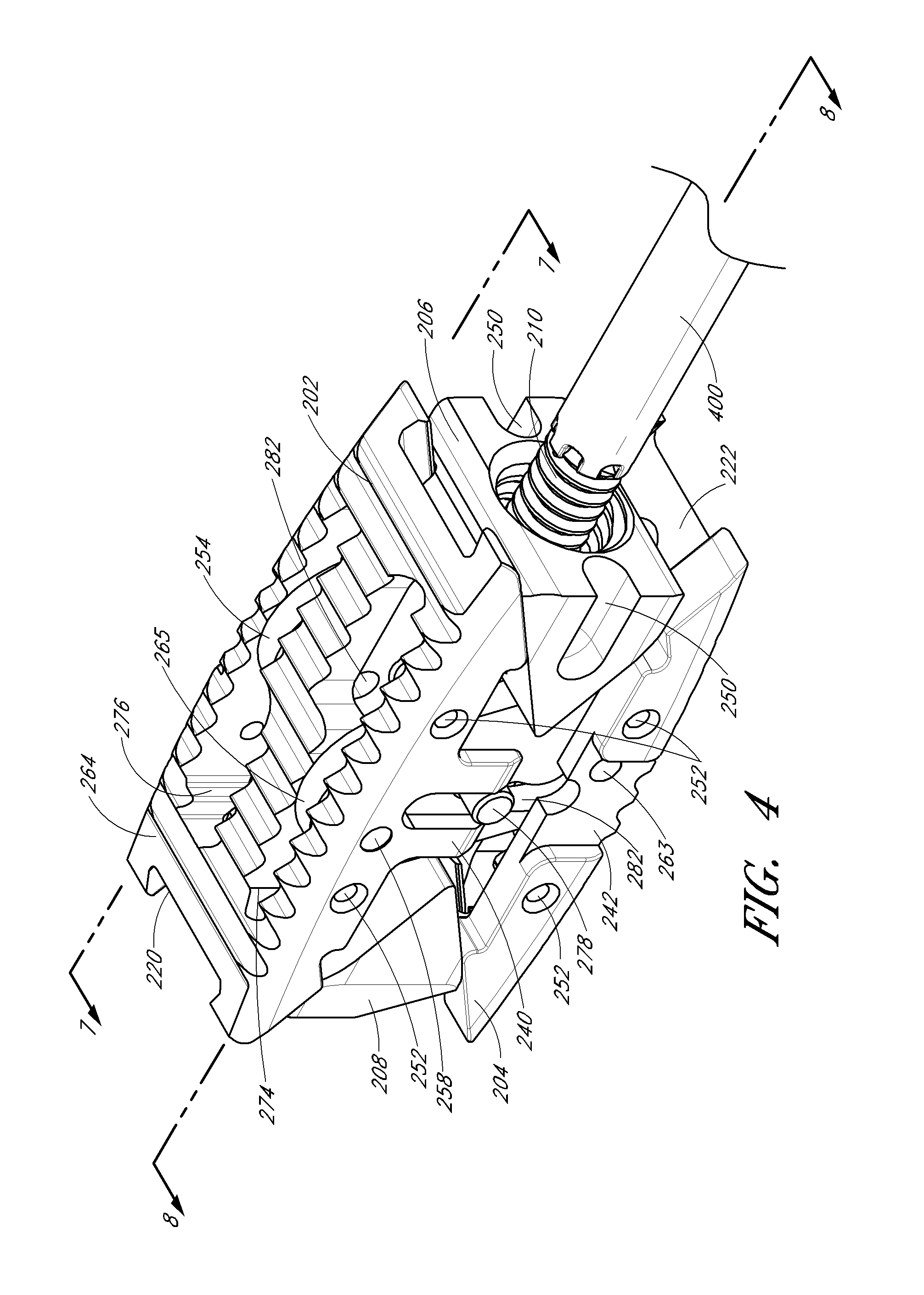
FIG. 4 is a perspective view of the intervertebral implant shown in FIG. 1 in an expanded state.
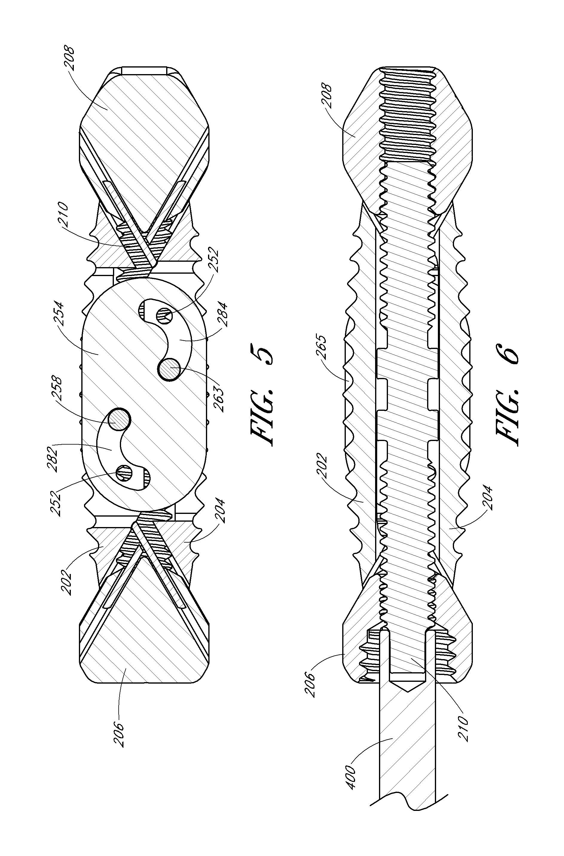
FIG. 5 is a side cross sectional view of the intervertebral implant shown in FIG. 3 in an unexpanded state, the cross sectional view is taken along line 5-5 of FIG. 3.
FIG. 6 is a side cross sectional view of the intervertebral implant shown in FIG. 3 in an unexpanded state, the cross sectional view is taken along line 6-6 of FIG. 3.
FIG. 7 is a side cross-sectional view of the intervertebral implant shown in FIG. 4 in an expanded state, the cross-sectional view is taken along line 7-7 of FIG. 4.
FIG. 8 is a side cross-sectional view of the intervertebral implant shown in FIG. 4 in an expanded state, the cross-sectional view is taken along line 8-8 of FIG. 4.
FIG. 9 is a bottom view of the intervertebral implant shown in FIG. 1 in an unexpanded state.
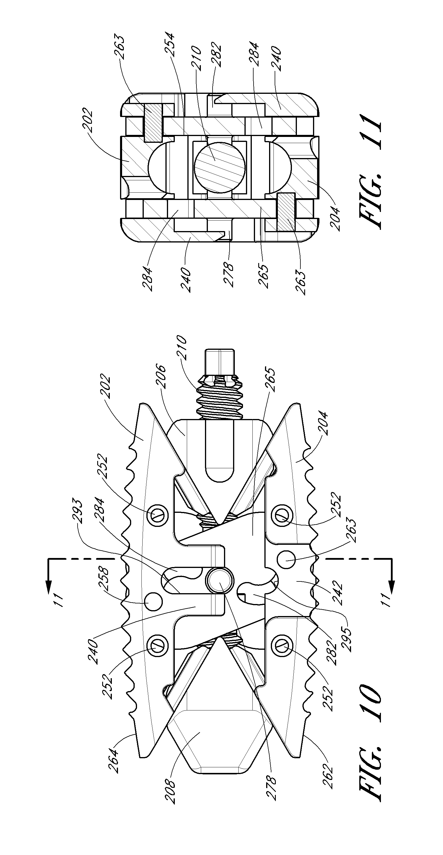
FIG. 10 is a side view of the intervertebral implant shown in FIG. 1 in an expanded state.
FIG. 11 is a front cross-sectional view of the intervertebral implant shown in FIG. 10 taken along lines 11-11.
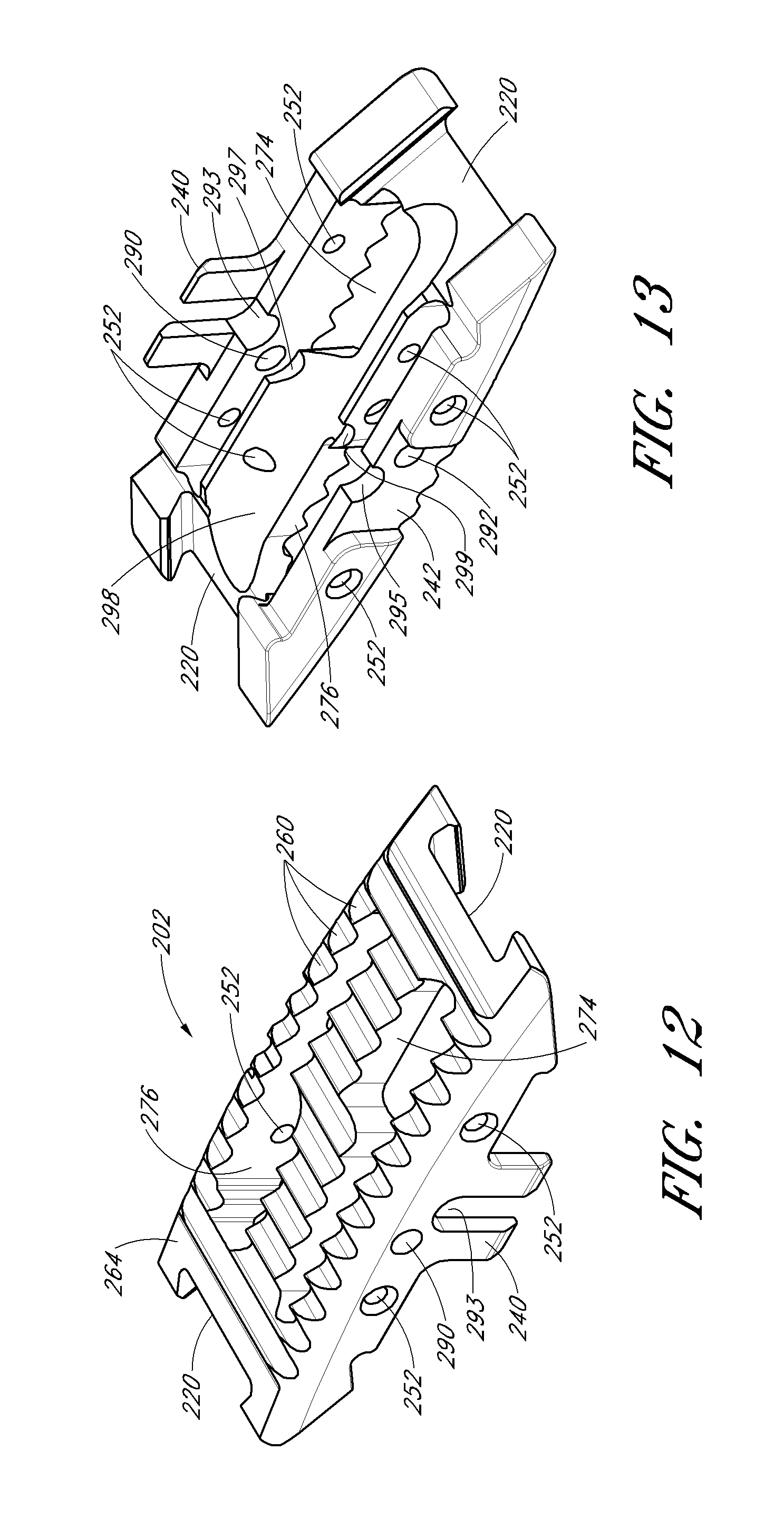
FIG. 12 is a top perspective view of an upper body portion of the intervertebral implant shown in FIG. 1.
FIG. 13 is a bottom perspective view of the upper body portion of the intervertebral implant shown in FIG. 1.
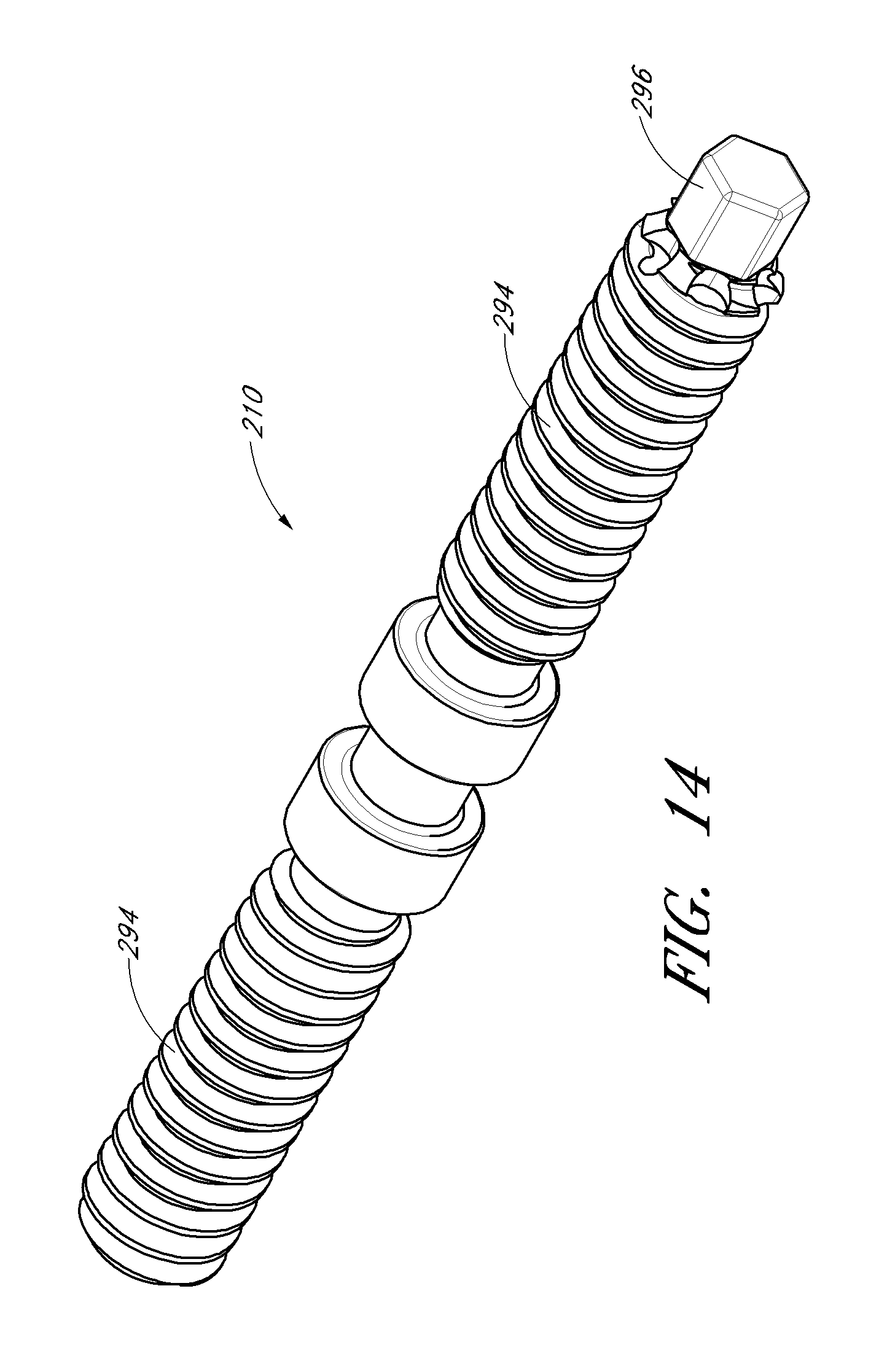
FIG. 14 is a perspective view of an actuator shaft of the intervertebral implant shown in FIG. 1.
FIG. 15 is a front perspective view of a proximal wedge member of the intervertebral implant shown in FIG. 1.
FIG. 16 is a rear perspective view of the proximal wedge member of the intervertebral implant shown in FIG. 1.
FIG. 17 is a front perspective view of a distal wedge member of the intervertebral implant shown in FIG. 1.
FIG. 18 is a rear perspective view of the distal wedge member of the intervertebral implant shown in FIG. 1.
FIG. 19A illustrates a perspective view of a linkage of the intervertebral implant shown in FIG. 1.
FIG. 19B illustrates a side view of the linkage illustrated in FIG. 19A.
FIG. 19C illustrates a top view of the linkage illustrated in FIG. 19A.
FIG. 20 is a perspective view of a long pin of the intervertebral implant shown in FIG. 1.
FIG. 21 is a perspective view of a short pin of the intervertebral implant shown in FIG. 1.
DETAILED DESCRIPTION
In accordance with certain embodiments disclosed herein, an improved intervertebral implant is provided that allows the clinician to insert the intervertebral implant through a minimally invasive procedure. For example, one or more intervertebral implants can be inserted percutaneously to reduce trauma to the patient and thereby enhance recovery and improve overall results of the surgery.
An intervertebral implant can include a plurality of body sections that are selectively separable and expandable upon contraction of a centrally disposed actuator. The actuator can be utilized to contract against faces of the body sections to cause the expansion thereof. The implant can also be configured such that the actuator provides for both the expansion and contraction of the body sections. The actuator can comprise an interaction between the body sections and another element, an action performed by another element, or a combination of interactions between various elements of the implant and its body sections. Further, the implant can be configured to allow either rough or fine incremental adjustments in the expansion of the implant.
The embodiments disclosed herein are discussed in the context of an intervertebral implant and spinal fusion because of the applicability and usefulness in such a field. As such, various embodiments can be used to properly space adjacent vertebrae in situations where a disc has ruptured or otherwise been damaged. As also disclosed herein, embodiments can also be used as vertebral body replacements. Thus, "adjacent" vertebrae can include those originally separated only by a disc or those that are separated by intermediate vertebra and discs. Such embodiments can therefore tend to recreate proper disc height and spinal curvature as required in order to restore normal anatomical locations and distances. However, it is contemplated that the teachings and embodiments disclosed herein can be beneficially implemented in a variety of other operational settings, for spinal surgery and otherwise.
For example, the implant disclosed herein can also be used as a vertebral body replacement. In such a use, the implant could be used as a replacement for a lumbar vertebra, such as one of the L1-L5 vertebrae. Thus, the implant could be appropriately sized and configured to be used intermediate adjacent vertebrae, or to entirely replace a damaged vertebra.
It is contemplated that the implant can be used as an interbody or intervertebral device or can be used to replace a vertebral body entirely. The implant can also be used in vertebral body compression fractures. Further, the implant can be used as a tool to expand an intervertebral space or bone in order to fill the space or bone with a cement; in such cases, the implant can be removed or left in once the cement is placed. Furthermore, the implant can also be used as a tool to pre-dilate the disc space. In some embodiments, the implant can be removed once the disc space is dilated, and a different implant (expandable or non-expandable) can then be implanted in the dilated disc space. The implant can also be introduced into the disc space anteriorly in an anterior lumbar interbody fusion (ALIF) procedure, posterior in an posterior lumbar interbody fusion (PILF) or posterior lateral interbody fusion, from extreme lateral position in an extreme lateral interbody fusion procedure (XLIF) or direct lateral interbody fusion (DLIF), from a far lateral position in a transforaminal lumbar interbody fusion (TLIF), to name a few. In other arrangements, the implant can be inserted through the Kambin triangle or be inserted through the Kambin triangle after the Kambin triangle has been enlarged via removing bone (e.g., techniques such as PerX360.degree. System.TM. sold by Intervention Spine.RTM.). Although the implant is primarily described herein as being used to expand in a vertical direction, it can also be implanted to expand in a horizontal direction in order to increase stability and/or increase surface area between adjacent vertebral bodies.
Therefore, it is contemplated that a number of advantages can be realized utilizing various embodiments disclosed herein. For example, as will be apparent from the disclosure, no external distraction of the spine is necessary. Further, no distraction device is required in order to install various embodiments disclosed herein. In this regard, embodiments of the implant can enable sufficient distraction of adjacent vertebra in order to properly restore disc height or to use the implant as a vertebral body replacement. Thus, normal anatomical locations, positions, and distances can be restored and preserved utilizing many of the embodiments disclosed herein.
Referring to FIG. 1, there is illustrated a side view of an embodiment of a intervertebral implant 200 in an unexpanded state while positioned generally between adjacent vertebrae of the lumbar portion of the spine 212. FIG. 2 illustrates the intervertebral implant 200 in an expanded state, thereby supporting the vertebrae in a desired orientation and spacing in preparation for spinal fusion. As is known in the art, spinal fusion is the process by which the adjacent vertebrae of the spine are united together ("fused") so that motion no longer occurs between the vertebrae. Thus, the intervertebral implant 200 can be used to provide the proper spacing two vertebrae to each other pending the healing of a fusion. See also U.S. Pat. No. 7,824,429, filed Jul. 18, 2003, the entirety of the disclosure of which is hereby incorporated by reference.
In certain embodiment, the implant can be installed in an operation that generally entails the following procedures. The damaged disc or vertebra can be decompressed, such as by distracting. The subject portion (or entire) disc or vertebra can then be removed. The adjacent vertebrae can be prepared by scraping the exposed adjacent portion or plates thereof (typically to facilitate bleeding and circulation in the area). Typically, most of the nucleus of the disc is removed and the annulus of the disc is thinned out. Although individual circumstances may vary, it may be unusual to remove all of the annulus or to perform a complete diskectomy. The implant can then be installed. In some embodiments, distraction of the disc may not be a separate step from placement of the implant; thus, distraction can be accomplished and can occur during placement of the implant. Finally, after implantation of the implant, osteogenic substances, such as autogenous bone graft, bone allograft, autograft foam, or bone morphogenic protein (BMP) can be strategically implanted adjacent the implant to prompt bone in-growth in the intervertebral space. In this regard, as the implant is expanded, the spaces within the implant can be backfilled; otherwise, the implant can be pre-packed with biologics.
The intervertebral implant is often used in combination with posterior and/or anterior fixation devices (e.g., rods, plates, screws, etc. that span two or more vertebrae) to limit movement during the fusion process. U.S. Pat. No. 7,824,429 discloses a particularly advantageous posterior fixation device and method which secures two adjacent vertebra to each other in a trans-laminar, trans-facet or facet-pedicle (e.g., the Boucher technique) application using fixation screws.
It should also be appreciated that in FIGS. 1 and 2 only one intervertebral implant 200 is shown positioned between the vertebrae 212. However, two, three, or more implants 200 can be inserted into the space between the vertebrae 212. Further, other devices, such as bone screws, can be used on the vertebrae as desired. For example, in a spinal fusion procedure, it is contemplated that one or more implants 200 can be used in conjunction with one or more bone screws and/or dynamic stabilization devices, such as those disclosed in the above-mentioned U.S. Pat. No. 7,824,429, filed Jul. 18, 2003.
In certain embodiments, the implant 200 can be used in combination with a dynamic stabilization devices such as those disclosed in U.S. Pat. No. 7,648,523, filed Feb. 11, 2005; U.S. Pat. No. 6,951,561, filed on May 6, 2004; U.S. Pat. No. 7,998,176, filed on Jun. 6, 2008; and U.S. Pat. No. 7,824,429, filed Jul. 18, 2003; the entireties of the disclosures of which are hereby incorporated by reference. In this manner, the implant 200 can be used to maintain height between vertebral bodies while the dynamic stabilization device provides limits in one or more degrees of movement.
FIG. 3 is a perspective view of an intervertebral implant 200 in an unexpanded state, and FIGS. 5 and 6 illustrate cross-sections of the intervertebral implant 200 in the unexpanded state. The implant 200 can comprise upper and lower body portions 202, 204, proximal and distal wedge members 206, 208, first and second linkages 254, 265, and an actuator shaft 210. In the unexpanded state, the upper and lower body portions 202, 204 can be generally abutting with a height of the implant 200 being minimized. However, the implant 200 can be expanded, as shown in FIG. 4, to increase the height of the implant 200 when implanted into the intervertebral space of the spine. FIGS. 7 and 8 illustrate cross-sections of the intervertebral implant 200 in the expanded state.
It is contemplated that the actuator shaft 210 can be rotated to cause the proximal and distal wedge members to move toward each other, thus causing the upper and lower body portions 202, 204 to be separated. In some embodiments, the implant 200 can include one or more linkages configured to connect the upper and lower body portions 202, 204 when the implant 200 is in an expanded state. For example, as shown in FIGS. 3 and 4, the implant 200 can include first and second linkages 254, 265. The linkages 254, 265 can be configured to move between a first configuration (shown in FIG. 5) and a second configuration (shown in FIG. 7).
Each of the intervertebral implant components will be described in further detail below in reference to FIGS. 9-21.
In some embodiments, the height of the implant 200 can be or vary within a range from at least about 6 mm to less than or equal to about 15 mm, and more preferably, from about 6.5 mm to about 12 mm. The width of the implant can be at least about 7 mm and/or less than or equal to about 18 mm, and preferably approximately 9 mm or 18 mm. Thus, the implant 200 can have a preferred aspect ratio of between approximately 6:18 and 15:7, and preferably approximately between 6.5:9 and 12:9, or between 6.5:18 and 12:18.
The length of the implant 200 can be or vary within a range from at least 18 mm to less than or equal to about 54 mm. In certain aspects, the length of the implant 200 can be or vary within a range from least about 18 mm to less than or equal to about 35 mm, and preferably from about 25 mm to about 31 mm. In certain aspects, the length of the implant 200 can be or vary within a range from least about 45 mm to less than or equal to about 54 mm. In some embodiments, the implant can have a greater length in the unexpanded state than in the expanded state. It is contemplated that various modifications to the dimension disclosed herein can be made by one of skill and the mentioned dimensions shall not be construed as limiting.
The intervertebral implant components can be manufactured in accordance with any of a variety of techniques which are well known in the art, using any of a variety of medical-grade construction materials. For example, the upper and lower body portions 202, 204, the actuator shaft 210, and other components can be injection-molded from a variety of medical-grade polymers including high or other density polyethylene, PEEK.TM. polymers, nylon and polypropylene.
The intervertebral implant 200 components can be molded, formed or machined from biocompatible metals such as Nitinol, stainless steel, titanium, and others known in the art. Non-metal materials such as plastics, PEEK.TM. polymers, and rubbers can also be used. Further, the implant components can be made of combinations of PEEK.TM. polymers and metals. In some embodiments, the intervertebral implant components can be injection-molded from a bioabsorbable material, to eliminate the need for a post-healing removal step.
The intervertebral implant components may be coated with or contain one or more bioactive substances, such as antibiotics, chemotherapeutic substances, angiogenic growth factors, substances for accelerating the healing of the wound, growth hormones, anti-thrombogenic agents, bone growth accelerators or agents, and the like. Such bioactive implants may be desirable because they contribute to the healing of the injury in addition to providing mechanical support. For example, in some embodiments, the upper and lower body portions 202, 204 can be coated with a bio-active coating, including, but not limited, to a hydroxyapatite coating, a titanium plasma spray, a resorbable blast media coating, or composite coatings. The upper and lower body portions 202, 204 can be coated after the implant is fully assembled, such that other components exposed along the upper and lower surfaces of the implant can also be coated with hydroxyapatite.
In some embodiments, the intervertebral implant components can be surface treated to increase the strength of the components. For example, the intervertebral implant components can be sand blasted, shot peened, laser peened, or otherwise treated to increase strength.
In addition, the intervertebral implant components may be provided with any of a variety of structural modifications to accomplish various objectives, such as osteoincorporation, or more rapid or uniform absorption into the body. For example, osteoincorporation may be enhanced by providing a micropitted or otherwise textured surface on the intervertebral implant components. Alternatively, capillary pathways may be provided throughout the intervertebral implant, such as by manufacturing the intervertebral implant components from an open cell foam material, which produces tortuous pathways through the device. This construction increases the surface area of the device which is exposed to body fluids, thereby generally increasing the absorption rate. Capillary pathways may alternatively be provided by laser drilling or other technique, which will be understood by those of skill in the art in view of the disclosure herein. Additionally, apertures can be provided in the implant to facilitate packing of biologics into the implant, backfilling, and/or osseointegration of the implant. In general, the extent to which the intervertebral implant can be permeated by capillary pathways or open cell foam passageways may be determined by balancing the desired structural integrity of the device with the desired reabsorption time, taking into account the particular strength and absorption characteristics of the desired polymer.
The implant 200 can be at least partially radiolucent, which radiolucency can allow a doctor to perceive the degree of bone growth around and through the implant. The individual components of the implant 200 can be fabricated of such materials based on needed structural, biological and optical properties.
The intervertebral implant may be sterilized by any of the well-known sterilization techniques, depending on the type of material. Suitable sterilization techniques include heat sterilization, ultrasonic sterilization, radiation sterilization, such as cobalt irradiation or electron beams, ethylene oxide sterilization, and the like.
FIG. 9 is a bottom view of the implant 200 shown in FIG. 3. As shown therein, each of the upper and lower body portions 202, 204 can also include one or more openings 274, 276 for receiving the first and second linkages 254, 265 and/or receiving graft material or other bioactive substances. The openings 274, 276 can be disposed on either side of a central receptacle 298 (FIG. 13).
In some embodiments, the two openings 274, 276 can be similarly shaped. For example, as shown in FIG. 9, each opening 274, 276 can include a first elongate portion having a width and a second portion having a width greater than the first elongate portion width. As shown in FIG. 9, at least a part of the actuator shaft 210 is visible through the second portion of each opening 274, 276. The second opening 276 can be disposed at a 180 degree angle from the first opening 274 and/or horizontally displaced from the first opening 274.
In certain variants, the openings 274, 276 can be single elongate portions through which the first and second linkages 254, 265 extend. Although not shown in the FIGS., the upper and lower body portions 202, 204 can include additional openings for receiving graft material or other bioactive substances. Each of the openings can be shaped similarly or differently. The additional openings can be vertically and/or horizontally displaced from each other along the upper and body portions 202, 204. The additional opens can be aligned with a longitudinal axis of the implant 200 or positioned off-center. One or more of the openings can be generally rounded, including, but not limited to, a generally elliptical shape, or include a light-bulb shape. The width of one or more of the openings can vary across a length of the opening.
In some embodiments, the implant 200 can comprise one or more protrusions 260 on a bottom surface 262 of the lower body portion 204. As shown in FIG. 12, the upper body portion 204 can also define a top surface having one or more protrusions 260 thereon. The protrusions 260 can allow the implant 200 to engage the adjacent vertebrae when the implant 200 is expanded to ensure that the implant 200 maintains a desired position in the intervertebral space.
The protrusions 260 can be configured in various patterns. As shown, the protrusions 260 can be formed from grooves extending widthwise along the bottom surface 262 of the implant 200 (also shown extending from a top surface 264 of the upper body portion 202 of the implant 200). The protrusions 260 can become increasingly narrow and pointed toward their apex. However, it is contemplated that the protrusions 260 can be one or more raised points, cross-wise ridges, or the like.
In FIG. 9, the implant 200 is illustrated in the unexpanded state with each of the respective slots 222 of the lower body portion 204 and lower guide members 270, 272 of the respective ones of the proximal and distal wedge members 206, 208. In some embodiments, as shown in FIGS. 12-13, the slots and guide members can be configured to incorporate a generally dovetail shape. Thus, once a given guide member is slid into engagement with a slot, the guide member can only slide longitudinally within the slot and not vertically from the slot. This arrangement can ensure that the proximal and distal wedge members 206, 208 are securely engaged with the upper and lower body portions 202, 204.
In FIG. 10, a side view of the embodiment of the implant 200 in the expanded state illustrates the angular relationship of the proximal and distal wedge members 206, 208 and the upper and lower body portions 202, 204. As mentioned above, the dovetail shape of the slots and guide members ensures that for each given slot and guide member, a given wedge member is generally interlocked with the give slot to only provide one degree of freedom of movement of the guide member, and thus the wedge member, in the longitudinal direction of the given slot.
Accordingly, in such an embodiment, the wedge members 206, 208 may not be separable from the implant when the implant 200 is in the unexpanded state (as shown in FIG. 3) due to the geometric constraints of the angular orientation of the slots and guide members with the actuator shaft inhibiting longitudinal relative movement of the wedge members 206, 208 relative to the upper and lower body portions 202, 204. Such a configuration ensures that the implant 200 is stable and structurally sound when in the unexpanded state or during expansion thereof, thus facilitating insertion and deployment of the implant 200.
Such an embodiment of the implant 200 can therefore be assembled by placing or engaging the wedge members 206, 208 with the actuator shaft 210, moving the wedge members 206, 208 axially together, and inserting the upper guide members 230, 232 into the slots 220 of the upper body portion 202 and the lower guide members 270, 272 into the slots 222 of the lower body portion 204. The wedge members 206, 208 can then be moved apart, which movement can cause the guide members and slots to engage and bring the upper and lower body portions toward each other. The implant 200 can then be prepared for insertion and deployment by reducing the implant 200 to the unexpanded state.
Referring again to FIG. 10, the implant 200 can define generally convex top and bottom surfaces 264, 262. This shape can be configured to generally match the concavity of adjacent vertebral bodies.
FIGS. 12-13 illustrate perspective views of the upper body portion 202 of the implant 200, according to an embodiment. These FIGS. provide additional clarity as to the configuration of the slots 220 and illustrate a first and second side portions 240, 242 of the upper body portion 202. The upper and lower body portions 202, 204 can also define a central receptacle 298 wherein the actuator shaft can be received, and two openings 274, 276 for receiving the first and second linkages 254, 265. Although the FIGS. illustrate the actuator shaft 210 disposed along a central receptacle 298 of the upper and lower body portions 202, 204, in certain variants, the actuator shaft 210 can be disposed off-center. This may be useful to provide a continuous graft channel along a central portion of the implant, from the top surface of the implant to the bottom surface of the implant.
It is contemplated that some embodiments of the implant 200 can be configured such that the upper and lower body portions 202, 204 each include side portions (shown as first side portion 240 and second side portion 242 of the upper body portion 202) to facilitate the alignment, interconnection, and stability of the components of the implant 200. The first and second side portions 240, 242 can be configured to have complementary structures that enable the upper and lower body portions 202, 204 to move in a vertical direction an maintain alignment in a horizontal direction. For example, as shown in FIGS. 12-13, the first side portion 240 can include an extending portion and the second side portion 242 can include a receiving portion for receiving the extending portion of the first side portion 240. As shown in FIG. 10, the first and second side portions 240, 242 of the upper body portion 202 can be configured to disengage from the first and second side portions 240, 242 of the lower body portion 202 when the implant 200 is in the expanded state.
FIG. 9 illustrates a bottom view of the profile of an embodiment of the first side portion 240 and the second side portion 242. As shown in FIG. 9, having a pair of each of first and second side portions 240, 242 can ensure that the upper and lower body portions 202, 204 do not translate relative to each other, thus further ensuring the stability of the implant 200.
In some embodiments, the implant 200 can be configured to include one or more apertures 252 to facilitate osseointegration of the implant 200 within the intervertebral space. As mentioned above, the implant 200 may contain one or more bioactive substances, such as antibiotics, chemotherapeutic substances, angiogenic growth factors, substances for accelerating the healing of the wound, growth hormones, anti-thrombogenic agents, bone growth accelerators or agents, and the like. Indeed, various biologics can be used with the implant 200 and can be inserted into the disc space or inserted along with the implant 200. The apertures 252 can facilitate circulation and bone growth throughout the intervertebral space and through the implant 200. In such implementations, the apertures 252 can thereby allow bone growth through the implant 200 and integration of the implant 200 with the surrounding materials.
As shown in FIG. 14, the actuator shaft 210 can have at least one thread 294 disposed along at least a portion thereof, if not along the entire length thereof. The actuator shaft 210 can be threadably and/or freely attached to one or both of the proximal and distal wedge members 206, 208. The actuator shaft 210 can also be configured such that a proximal portion of the actuator shaft 210 can be removed after the implant 200 has been expanded in order to eliminate any proximal protrusion of the actuator shaft 210. Although, the present embodiment is illustrated using this mode of expansion, it is contemplated that other modes of expansion (e.g., one way-ratchet type mechanism) can be combined with or interchanged herewith.
The threads can be configured to be left hand threads at a distal end of the actuator shaft 210 and right hand threads at a proximal other end of the actuator shaft 210 for engaging the respective ones of the distal and proximal wedge members 208, 206. Accordingly, upon rotation of the actuator shaft 210, the wedge members 206, 208 can be caused to move toward or away from each other to facilitate expansion or contraction of the implant 200.
In some embodiments, the actuator shaft 210 can facilitate expansion of the implant 200 through rotation, longitudinal contract of the pin, or other mechanisms. The actuator shaft 210 can include threads that threadably engage at least one of the proximal and distal wedge members 206, 208. The actuator shaft 210 can also facilitate expansion through longitudinal contraction of the actuator shaft as proximal and distal collars disposed on inner and outer sleeves move closer to each other to in turn move the proximal and distal wedge members closer together. It is contemplated that in certain variants, at least a portion of the actuator shaft can be axially fixed relative to one of the proximal and distal wedge members 206, 208 with the actuator shaft being operative to move the other one of the proximal and distal wedge members 206, 208 via rotational movement or longitudinal contraction of the pin.
In some embodiments, wherein the actuator shaft 210 is threaded, it is contemplated that the actuator shaft 210 can be configured to bring the proximal and distal wedge members closer together at different rates. In such embodiments, the implant 200 could be expanded to a V-configuration or wedged shape. For example, the actuator shaft 210 can comprise a variable pitch thread that causes longitudinal advancement of the distal and proximal wedge members at different rates. The advancement of one of the wedge members at a faster rate than the other could cause one end of the implant to expand more rapidly and therefore have a different height that the other end. Such a configuration can be advantageous depending on the intervertebral geometry and circumstantial needs.
The actuator shaft 210 can be utilized to provide a stabilizing axial force to the proximal and distal wedge members 206, 208 in order to maintain the expansion of the implant 200. However, it is also contemplated that other features can be incorporated into such an embodiment to facilitate the maintenance of the expansion. In this regard, although the axial force provided by the actuator shaft 210 can tend to maintain the position and stability of the proximal and distal wedge members 206, 208, additional features can be employed to ensure the strength and stability of the implant 200 when in its expanded state. For example, the proximal and distal wedge members 206, 208 can include ribbed engagement surfaces (not shown). The use of the ribbed engagement surfaces can permit one-way, ratchet type longitudinal movement of proximal and distal wedge members 206, 208 relative to the upper and lower body portions 202, 204 in order to maintain the upper and lower body portions at a given separation distance. Various other features that can be used to facilitate the expansion of two body portions of an intervertebral implant are disclosed in U.S. Pat. No. 8,105,382, filed Dec. 7, 2007, the entirety of which is hereby incorporated by reference.
The actuator shaft 210 can be cannulated and/or include one or more apertures. The one or more apertures and/or cannula can provide access to an internal portion of the implant, so bone graft or other bioactive materials described herein can be directly injected into the implant to promote fusion.
In accordance with an embodiment, the actuator shaft 210 can also comprise a tool engagement section 296. The tool engagement section 296 can be configured as a to be engaged by a tool 400. The tool engagement section 296 can be shaped as a polygon, such as a hex shape to facilitate the transfer of torque to the actuator shaft 210 from the tool 400. For example, the tool 400 can include a distal engagement member 430 being configured to engage a proximal end of the actuator shaft 210 of the implant 200 for rotating the actuator shaft 210 to thereby expand the implant from an unexpanded state to and expanded state.
The proximal end of the actuator shaft can also include a number of tool engagement features configured to engage with a number of corresponding engagement features at a distal end of the tool 400 (shown in FIG. 4). These tool engagement features can be configured to increase torque strength and facilitate rotation of the actuator shaft. As shown in FIG. 14, the tool engagement features can take the form of one or more grooves or indentations. The number of tool engagement features can equal the number of faces on the tool engagement section. For example, the actuator shaft 210 can include six tool engagement features. The tool engagement features can be disposed at a proximal end of the actuator shaft 210, between the threaded portion 294 and the tool engagement section 296. In certain aspects, the tool engagement features can surround a base of the tool engagement section 296. FIG. 4 illustrates the corresponding engagement features of the tool 400. The corresponding features can take the form of protrusions, nubs, fingers, or otherwise, at the distal end of the tool 400.
FIG. 15-16 illustrate perspective views of the proximal wedge member 206 of the implant 200. The proximal wedge member 206 can include one or more anti-torque structures 250. Further, the guide members 230, 270 are also illustrated. The proximal wedge member 206 can comprise a central aperture 300 wherethrough an actuator shaft can be received. When actuator shaft 210 is used in an embodiment, the central aperture 300 can be threaded to correspond to the threads 294 of the actuator shaft 210. In other embodiments, the actuator shaft can engage other portions of the wedge member 206 for causing expansion or contraction thereof.
In some embodiments, the implant 200 can be configured such that the proximal and distal wedge members 206, 208 are interlinked with the upper and lower body portions 202, 204 to improve the stability and alignment of the implant 200. For example, the upper and lower body portions 202, 204 can be configured to include slots (slot 220 is shown in FIG. 3, and slots 220, 222 are shown in FIG. 4). The proximal and distal wedge members 206, 208 can be configured to include at least one guide member (an upper guide member 230 of the proximal wedge member 206 is shown in FIGS. 15-16 and an upper guide member 232 of the distal wedge member 208 is shown in FIGS. 17-18) that at least partially extends into a respective slot 220, 222 of the upper and lower body portions 202, 204. The arrangement of the slots and the guide members can enhance the structural stability and alignment of the implant 200.
In some embodiments, the implant 200 can be configured to include anti-torque structures 250. The anti-torque structures 250 can interact with at least a portion of a deployment tool during deployment of the implant to ensure that the implant maintains its desired orientation. For example, when the implant 200 is being deployed and a rotational force is exerted on the actuator shaft 210, the anti-torque structures 250 can be engaged by a non-rotating structure of the deployment tool to maintain the rotational orientation of the implant 200 while the actuator shaft 210 is rotated. The anti-torque structures 250 can comprise one or more inwardly extending holes or indentations on the proximal wedge member 206, which are shown as a pair of holes in FIGS. 3-4. However, the anti-torque structures 250 can also comprise one or more outwardly extending structures.
The tool 400 can also include an anti-torque component to engage one or more anti-torque structures 250 of the implant 200. The anti-torque component can include one or more protrusions that engage the anti-torque structures 250 to prevent movement of the implant 200 when a rotational force is applied to the actuator shaft 210 via the tool 400. Other deployment methods can also be used, such as those disclosed in U.S. Pat. No. 8,105,382.
FIG. 17-18 illustrate perspective views of the distal wedge member 208 of the implant 200. As similarly discussed above with respect to the proximal wedge member 206, the guide members 232, 272 and a central aperture 302 of the proximal wedge member 206 are illustrated. The central aperture 302 can be configured to receive an actuator shaft therethrough. When actuator shaft 210 is used in an embodiment, the central aperture 302 can be threaded to correspond to the threads 294 of the actuator shaft 210. In other embodiments, the actuator shaft can engage other portions of the wedge member 208 for causing expansion or contraction thereof.
As shown in FIGS. 19A-19C, each linkage 254, 265 can have a width W and a length L. The length L can be substantially longer than the width W. In some embodiments, the length L can be at least two times the width W, at least three times the W, or otherwise. Each linkage 254, 265 can include one or more cam paths 282, 284 through which a long pin 258 (FIG. 20) or a short pin 263 (FIG. 21) can move. Each linkage can also include shaft portions 278, 286. The axis extending through the shaft portions 278, 286 can be substantially transverse to the longitudinal axis of the linkages 254, 265. Shaft portion 278 can be longer than shaft portion 286.
The linkages can be positioned such that the longer shaft portion 278 can engage the side portions 240, 242 of the upper and lower body portions 202, 204. For example, each of the side portions 240, 242 can include a receiving portion 293, 295 for receiving the longer shaft portion 278 when the implant 202 is in the unexpanded state. Each of the upper and lower body portions 202, 204 can also include internal receiving portions 297, 299 for receiving the shorter shaft portions 286 when the implant 200 is in the unexpanded state. The receiving portions can be slots, grooves, indentations, or other features capable of receiving the shaft portions 278, 286.
The linkages 254, 265 can facilitate the alignment, interconnection, and stability of the upper and lower body portions 202, 204. As shown in FIG. 4, the long and short pins 258, 263 can connect the linkages 254, 265 to the upper and lower body portions 202, 204. The upper and lower body portions 202, 204 can each include apertures 290, 292 for receiving the pins 258, 263 (shown in FIGS. 12-13). For example, the long pin 258 can extend from the cam path 284 to the side portion aperture 290 disposed on the first side portion 240, and the short pin 263 can extend from the cam path 282 to the to the side portion aperture 292 disposed on the second side portion 242. FIG. 11 illustrates how the upper and lower body portions 202, 204 can connect to linkages 254, 265 via the pins 263. FIG. 11 illustrates a cross-section of FIG. 10 taken along line 11-11.
In addition, the linkages 254, 265 can act as motion limiting structures that limit the separation between the upper and lower body portions 202, 204. As the upper and lower side portions 202, 204 move apart, the pins 258, 263 move along their respective cam paths 282, 284 and force the linkages 254, 265 to rotate from the first configuration to the second configuration. In the first configuration, an axis extending across the width W of each linkage 254, 265 is substantially transverse to a longitudinal axis of the implant 200. In the second configuration, the axis extending across the width W of each linkage 254, 265 is nearly or substantially parallel to the longitudinal axis of the implant 200. The upper and lower body portions 202, 204 can only move apart so far as the linkages 254, 265 will permit. As such, the distance between the upper and lower body portions 202, 204 is limited by the distance between far ends of cam paths 282, 284.
Although not shown in the FIGS., the implant 200 can include additional linkages to provide further stability. Each of the additional linkages can connect to the upper and lower body portions 202, 204 as described above. For example, the additional linkages can be horizontally displaced from the first and second linkages 254, 265 described herein. In certain variants, the additional linkages can connect to the first and second linkages 254, 265 to permit further expansion of the upper and lower body portions 202, 204. For example, the upper and lower body portions 202, 204 can be separated by a distance equivalent to two linkages.
The specific dimensions of any of the embodiment disclosed herein can be readily varied depending upon the intended application, as will be apparent to those of skill in the art in view of the disclosure herein. Moreover, although the present inventions have been described in terms of certain preferred embodiments, other embodiments of the inventions including variations in the number of parts, dimensions, configuration and materials will be apparent to those of skill in the art in view of the disclosure herein. In addition, all features discussed in connection with any one embodiment herein can be readily adapted for use in other embodiments herein to form various combinations and sub-combinations. The use of different terms or reference numerals for similar features in different embodiments does not imply differences other than those which may be expressly set forth. Accordingly, the present inventions are intended to be described solely by reference to the appended claims, and not limited to the preferred embodiments disclosed herein.
* * * * *
D00000
D00001
D00002
D00003
D00004
D00005
D00006
D00007
D00008
D00009
D00010
D00011
D00012
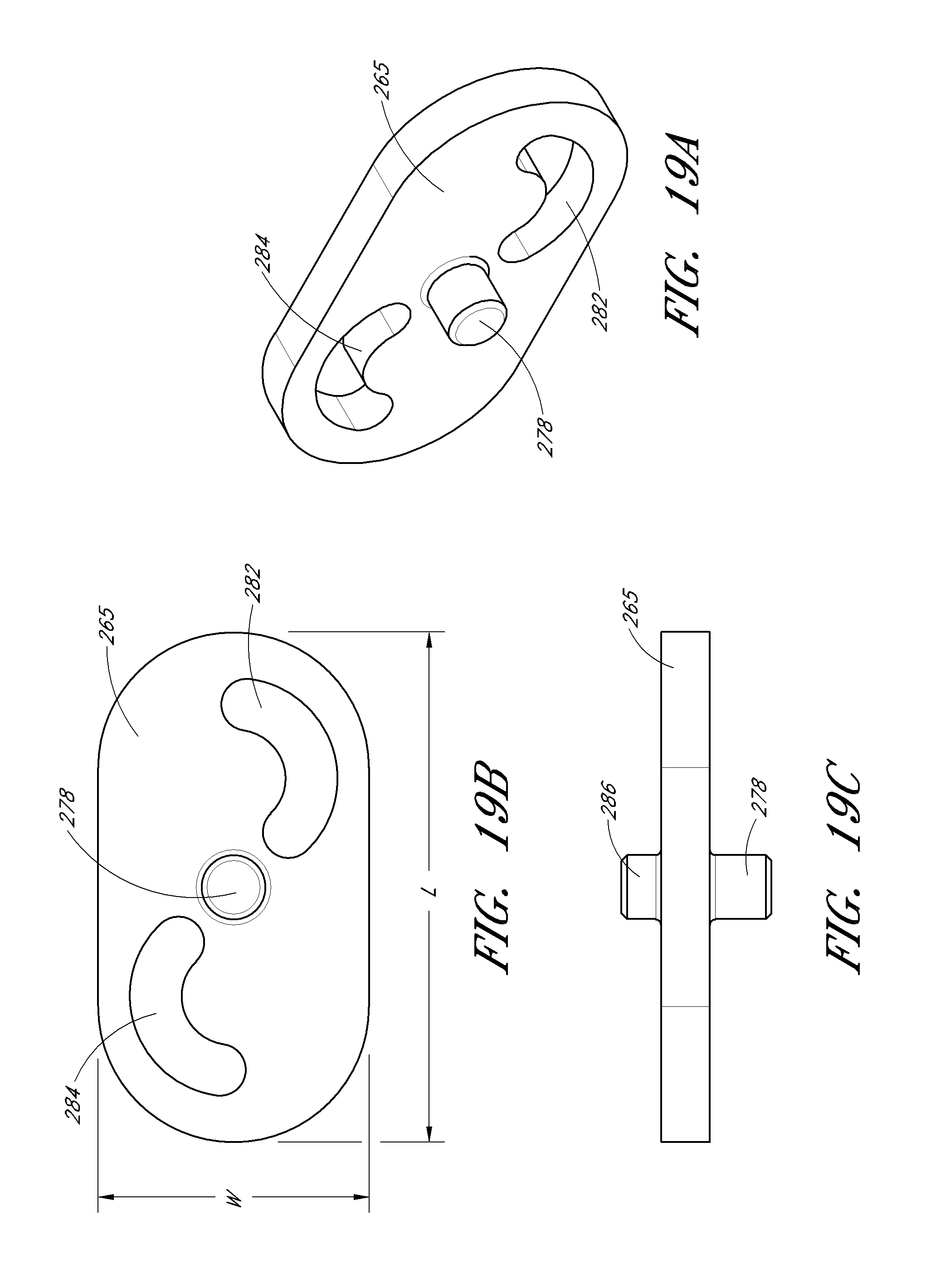
D00013
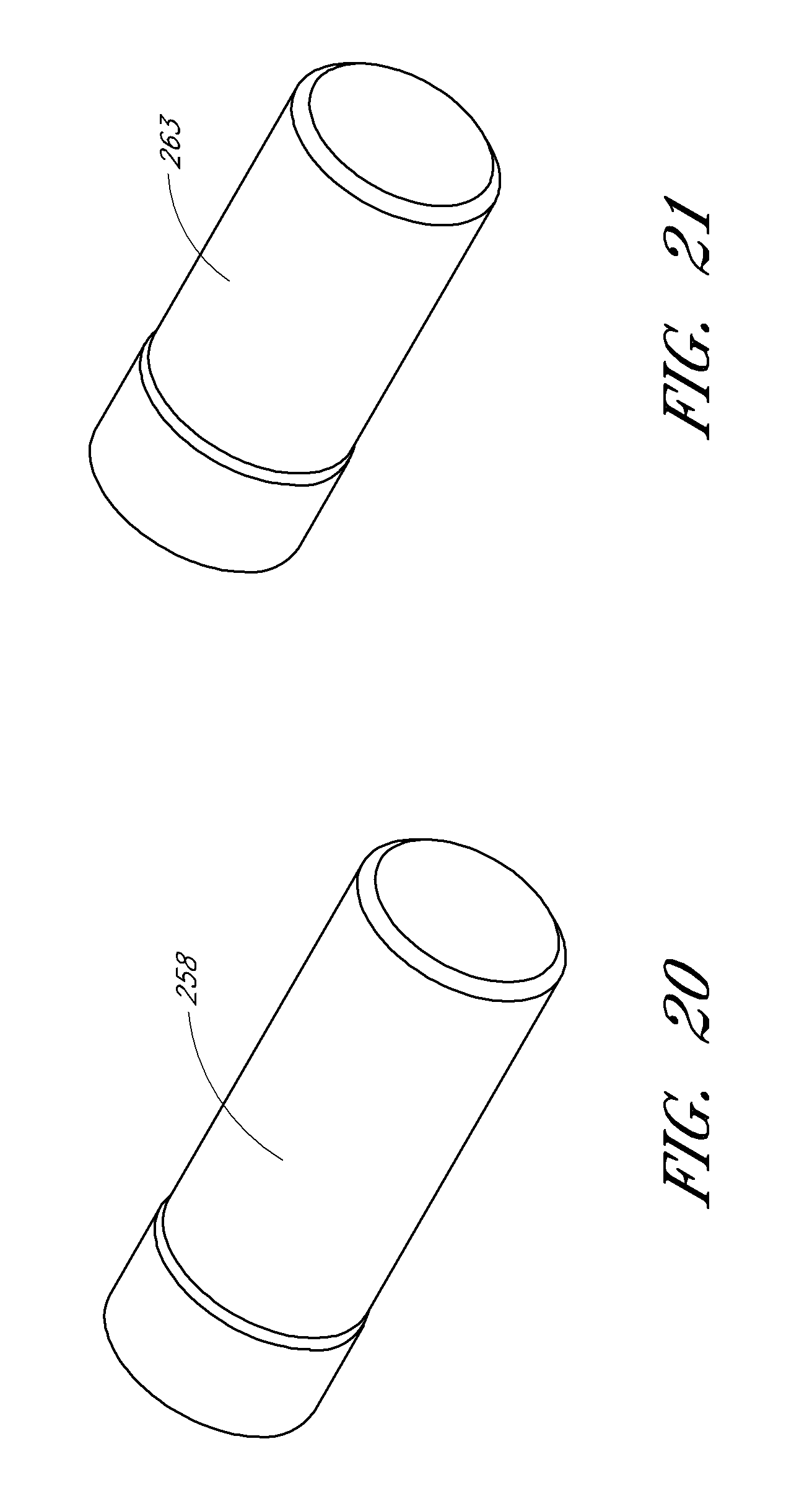
XML
uspto.report is an independent third-party trademark research tool that is not affiliated, endorsed, or sponsored by the United States Patent and Trademark Office (USPTO) or any other governmental organization. The information provided by uspto.report is based on publicly available data at the time of writing and is intended for informational purposes only.
While we strive to provide accurate and up-to-date information, we do not guarantee the accuracy, completeness, reliability, or suitability of the information displayed on this site. The use of this site is at your own risk. Any reliance you place on such information is therefore strictly at your own risk.
All official trademark data, including owner information, should be verified by visiting the official USPTO website at www.uspto.gov. This site is not intended to replace professional legal advice and should not be used as a substitute for consulting with a legal professional who is knowledgeable about trademark law.