Implant having multiple adjustment mechanisms
Miller , et al.
U.S. patent number 10,363,136 [Application Number 15/717,440] was granted by the patent office on 2019-07-30 for implant having multiple adjustment mechanisms. This patent grant is currently assigned to Valtech Cardio, Ltd.. The grantee listed for this patent is Valtech Cardio, Ltd.. Invention is credited to Oz Cabiri, Amir Gross, Eran Miller, Tal Reich, Tal Sheps.


View All Diagrams
| United States Patent | 10,363,136 |
| Miller , et al. | July 30, 2019 |
Implant having multiple adjustment mechanisms
Abstract
A method is provided for use with an implant structure, a first tool, a second tool, and a longitudinal guide member. The implant structure is delivered to a heart of a subject, the implant structure including: (i) a first adjustment mechanism to which the first tool is coupled, and (ii) a second adjustment mechanism to which the longitudinal guide member is coupled. The implant structure is then coupled to tissue of the heart. Subsequently, the second tool is advanced along the longitudinal guide member to the second adjustment mechanism.
| Inventors: | Miller; Eran (Moshav Beit Elazari, IL), Reich; Tal (Moledet, IL), Gross; Amir (Tel Aviv-Jaffa, IL), Sheps; Tal (Givat Shmuel, IL), Cabiri; Oz (Hod Hasharon, IL) | ||||||||||
|---|---|---|---|---|---|---|---|---|---|---|---|
| Applicant: |
|
||||||||||
| Assignee: | Valtech Cardio, Ltd. (Or
Yehuda, IL) |
||||||||||
| Family ID: | 48224232 | ||||||||||
| Appl. No.: | 15/717,440 | ||||||||||
| Filed: | September 27, 2017 |
Prior Publication Data
| Document Identifier | Publication Date | |
|---|---|---|
| US 20180014934 A1 | Jan 18, 2018 | |
Related U.S. Patent Documents
| Application Number | Filing Date | Patent Number | Issue Date | ||
|---|---|---|---|---|---|
| 14990172 | Jan 7, 2016 | 9775709 | |||
| 14486226 | Feb 23, 2016 | 9265608 | |||
| 13666262 | Oct 14, 2014 | 8858623 | |||
| 61555570 | Nov 4, 2011 | ||||
| Current U.S. Class: | 1/1 |
| Current CPC Class: | A61F 2/2448 (20130101); A61F 2/2466 (20130101); A61F 2/2445 (20130101); A61F 2/2454 (20130101); A61F 2/2457 (20130101); A61F 2250/001 (20130101) |
| Current International Class: | A61F 2/24 (20060101) |
References Cited [Referenced By]
U.S. Patent Documents
| 3604488 | September 1971 | Wishart et al. |
| 3656185 | April 1972 | Carpentier |
| 3840018 | October 1974 | Heifetz |
| 3881366 | May 1975 | Bradley et al. |
| 3898701 | August 1975 | La Russa |
| 4042979 | August 1977 | Angell |
| 4118805 | October 1978 | Reimels |
| 4214349 | July 1980 | Munch |
| 4261342 | April 1981 | Aranguren Duo |
| 4290151 | September 1981 | Massana |
| 4434828 | March 1984 | Trincia |
| 4473928 | October 1984 | Johnson |
| 4602911 | July 1986 | Ahmadi et al. |
| 4625727 | December 1986 | Leiboff |
| 4712549 | December 1987 | Peters et al. |
| 4778468 | October 1988 | Hunt et al. |
| 4917698 | April 1990 | Carpentier et al. |
| 4961738 | October 1990 | Mackin |
| 5042707 | August 1991 | Taheri |
| 5061277 | October 1991 | Carpentier et al. |
| 5064431 | November 1991 | Gilbertson et al. |
| 5104407 | April 1992 | Lam et al. |
| 5108420 | April 1992 | Marks |
| 5201880 | April 1993 | Wright et al. |
| 5258008 | November 1993 | Wilk |
| 5300034 | April 1994 | Behnke et al. |
| 5306296 | April 1994 | Wright et al. |
| 5325845 | July 1994 | Adair |
| 5346498 | September 1994 | Greelis et al. |
| 5383852 | January 1995 | Stevens-Wright |
| 5449368 | September 1995 | Kuzmak |
| 5450860 | September 1995 | O'Connor |
| 5464404 | November 1995 | Abela et al. |
| 5474518 | December 1995 | Farrer Velazquez |
| 5477856 | December 1995 | Lundquist |
| 5593424 | January 1997 | Northrup, III |
| 5601572 | February 1997 | Middleman et al. |
| 5626609 | May 1997 | Zvenyatsky et al. |
| 5643317 | July 1997 | Pavcnik et al. |
| 5669919 | September 1997 | Sanders et al. |
| 5674279 | October 1997 | Wright et al. |
| 5676653 | October 1997 | Taylor et al. |
| 5683402 | November 1997 | Cosgrove et al. |
| 5702397 | December 1997 | Goble et al. |
| 5702398 | December 1997 | Tarabishy |
| 5709695 | January 1998 | Northrup, III |
| 5716370 | February 1998 | Williamson, IV et al. |
| 5716397 | February 1998 | Myers |
| 5728116 | March 1998 | Rosenman |
| 5730150 | March 1998 | Peppel et al. |
| 5749371 | May 1998 | Zadini et al. |
| 5782844 | July 1998 | Yoon et al. |
| 5810882 | September 1998 | Bolduc et al. |
| 5824066 | October 1998 | Gross |
| 5830221 | November 1998 | Stein et al. |
| 5843120 | December 1998 | Israel et al. |
| 5855614 | January 1999 | Stevens et al. |
| 5876373 | March 1999 | Giba et al. |
| 5935098 | August 1999 | Blaisdell et al. |
| 5957953 | September 1999 | DiPoto et al. |
| 5961440 | October 1999 | Schweich, Jr. et al. |
| 5961539 | October 1999 | Northrup, III et al. |
| 5984959 | November 1999 | Robertson et al. |
| 6001127 | December 1999 | Schoon et al. |
| 6042554 | March 2000 | Rosenman et al. |
| 6045497 | April 2000 | Schweich, Jr. et al. |
| 6050936 | April 2000 | Schweich, Jr. et al. |
| 6059715 | May 2000 | Schweich, Jr. et al. |
| 6074341 | June 2000 | Anderson et al. |
| 6074401 | June 2000 | Gardiner et al. |
| 6074417 | June 2000 | Peredo |
| 6086582 | July 2000 | Altman et al. |
| 6102945 | August 2000 | Campbell |
| 6106550 | August 2000 | Magovern et al. |
| 6110200 | August 2000 | Hinnenkamp |
| 6132390 | October 2000 | Cookston et al. |
| 6143024 | November 2000 | Campbell et al. |
| 6159240 | December 2000 | Sparer et al. |
| 6165119 | December 2000 | Schweich, Jr. et al. |
| 6174332 | January 2001 | Loch et al. |
| 6183411 | February 2001 | Mortier et al. |
| 6187040 | February 2001 | Wright |
| 6210347 | April 2001 | Forsell |
| 6217610 | April 2001 | Carpentier et al. |
| 6231602 | May 2001 | Carpentier et al. |
| 6251092 | June 2001 | Qin et al. |
| 6296656 | October 2001 | Bolduc et al. |
| 6315784 | November 2001 | Djurovic |
| 6319281 | November 2001 | Patel |
| 6328746 | December 2001 | Gambale |
| 6332893 | December 2001 | Mortier et al. |
| 6355030 | March 2002 | Aldrich et al. |
| 6361559 | March 2002 | Houser et al. |
| 6368348 | April 2002 | Gabbay |
| 6402780 | June 2002 | Williamson, IV et al. |
| 6406420 | June 2002 | McCarthy et al. |
| 6406493 | June 2002 | Tu et al. |
| 6419696 | July 2002 | Ortiz et al. |
| 6451054 | September 2002 | Stevens |
| 6458076 | October 2002 | Pruitt |
| 6461366 | October 2002 | Seguin |
| 6470892 | October 2002 | Forsell |
| 6503274 | January 2003 | Howanec, Jr. et al. |
| 6524338 | February 2003 | Gundry |
| 6530952 | March 2003 | Vesely |
| 6533772 | March 2003 | Sheds et al. |
| 6537314 | March 2003 | Langberg et al. |
| 6547801 | April 2003 | Dargent et al. |
| 6554845 | April 2003 | Fleenor et al. |
| 6564805 | May 2003 | Garrison et al. |
| 6565603 | May 2003 | Cox |
| 6569198 | May 2003 | Wilson et al. |
| 6579297 | June 2003 | Bicek et al. |
| 6589160 | July 2003 | Schweich, Jr. et al. |
| 6592593 | July 2003 | Parodi et al. |
| 6602288 | August 2003 | Cosgrove et al. |
| 6602289 | August 2003 | Colvin et al. |
| 6613078 | September 2003 | Barone |
| 6613079 | September 2003 | Wolinsky et al. |
| 6619291 | September 2003 | Hlavka et al. |
| 6626899 | September 2003 | Houser et al. |
| 6626917 | September 2003 | Craig |
| 6626930 | September 2003 | Allen et al. |
| 6629534 | October 2003 | St. Goar et al. |
| 6629921 | October 2003 | Schweich, Jr. et al. |
| 6651671 | November 2003 | Donlon et al. |
| 6652556 | November 2003 | VanTassel et al. |
| 6682558 | January 2004 | Tu et al. |
| 6689125 | February 2004 | Keith et al. |
| 6689164 | February 2004 | Seguin |
| 6695866 | February 2004 | Kuehn et al. |
| 6702826 | March 2004 | Liddicoat et al. |
| 6702846 | March 2004 | Mikus et al. |
| 6706065 | March 2004 | Langberg et al. |
| 6709385 | March 2004 | Forsell |
| 6709456 | March 2004 | Langberg et al. |
| 6711444 | March 2004 | Koblish |
| 6718985 | April 2004 | Hlavka et al. |
| 6719786 | April 2004 | Ryan et al. |
| 6723038 | April 2004 | Schroeder et al. |
| 6726716 | April 2004 | Marquez |
| 6726717 | April 2004 | Alfieri et al. |
| 6730121 | May 2004 | Ortiz et al. |
| 6749630 | June 2004 | McCarthy et al. |
| 6752813 | June 2004 | Goldfarb et al. |
| 6764310 | July 2004 | Ichihashi et al. |
| 6764510 | July 2004 | Vidlund et al. |
| 6764810 | July 2004 | Ma et al. |
| 6770083 | August 2004 | Seguin |
| 6786924 | September 2004 | Ryan et al. |
| 6786925 | September 2004 | Schoon et al. |
| 6790231 | September 2004 | Liddicoat et al. |
| 6797001 | September 2004 | Mathis et al. |
| 6797002 | September 2004 | Spence et al. |
| 6802319 | October 2004 | Stevens et al. |
| 6805710 | October 2004 | Bolling et al. |
| 6805711 | October 2004 | Quijano et al. |
| 6855126 | February 2005 | Flinchbaugh |
| 6858039 | February 2005 | McCarthy |
| 6884250 | April 2005 | Monassevitch et al. |
| 6893459 | May 2005 | Macoviak |
| 6908478 | June 2005 | Alferness et al. |
| 6908482 | June 2005 | McCarthy et al. |
| 6918917 | July 2005 | Nguyen et al. |
| 6926730 | August 2005 | Nguyen et al. |
| 6960217 | November 2005 | Bolduc |
| 6964684 | November 2005 | Ortiz et al. |
| 6964686 | November 2005 | Gordon |
| 6976995 | December 2005 | Mathis et al. |
| 6986775 | January 2006 | Morales et al. |
| 6989028 | January 2006 | Lashinski et al. |
| 6997951 | February 2006 | Solem et al. |
| 7004176 | February 2006 | Lau |
| 7007798 | March 2006 | Happonen et al. |
| 7011669 | March 2006 | Kimblad |
| 7011682 | March 2006 | Lashinski et al. |
| 7018406 | March 2006 | Seguin et al. |
| 7037334 | May 2006 | Hlavka et al. |
| 7077850 | July 2006 | Kortenbach |
| 7077862 | July 2006 | Vidlund et al. |
| 7087064 | August 2006 | Hyde |
| 7101395 | September 2006 | Tremulis et al. |
| 7101396 | September 2006 | Artof et al. |
| 7112207 | September 2006 | Allen et al. |
| 7118595 | October 2006 | Ryan et al. |
| 7125421 | October 2006 | Tremulis et al. |
| 7150737 | December 2006 | Purdy et al. |
| 7159593 | January 2007 | McCarthy et al. |
| 7166127 | January 2007 | Spence et al. |
| 7169187 | January 2007 | Datta et al. |
| 7172625 | February 2007 | Shu et al. |
| 7175660 | February 2007 | Cartledge et al. |
| 7186262 | March 2007 | Saadat |
| 7186264 | March 2007 | Liddicoat et al. |
| 7189199 | March 2007 | McCarthy et al. |
| 7192443 | March 2007 | Solem et al. |
| 7220277 | May 2007 | Arru et al. |
| 7226467 | June 2007 | Lucatero et al. |
| 7226477 | June 2007 | Cox |
| 7226647 | June 2007 | Kasperchik et al. |
| 7229452 | June 2007 | Kayan |
| 7238191 | July 2007 | Bachmann |
| 7288097 | October 2007 | Seguin |
| 7294148 | November 2007 | McCarthy |
| 7297150 | November 2007 | Cartledge et al. |
| 7311728 | December 2007 | Solem et al. |
| 7311729 | December 2007 | Mathis et al. |
| 7314485 | January 2008 | Mathis |
| 7316710 | January 2008 | Cheng et al. |
| 7329279 | February 2008 | Haug et al. |
| 7329280 | February 2008 | Bolling et al. |
| 7335213 | February 2008 | Hyde et al. |
| 7361190 | April 2008 | Shaoulian et al. |
| 7364588 | April 2008 | Mathis et al. |
| 7377941 | May 2008 | Rhee et al. |
| 7390329 | June 2008 | Westra et al. |
| 7404824 | July 2008 | Webler et al. |
| 7431692 | October 2008 | Zollinger et al. |
| 7442207 | October 2008 | Rafiee |
| 7452376 | November 2008 | Lim et al. |
| 7455690 | November 2008 | Cartledge et al. |
| 7485142 | February 2009 | Milo |
| 7485143 | February 2009 | Webler et al. |
| 7500989 | March 2009 | Solem et al. |
| 7507252 | March 2009 | Lashinski et al. |
| 7510575 | March 2009 | Spenser et al. |
| 7510577 | March 2009 | Moaddeb et al. |
| 7527647 | May 2009 | Spence |
| 7530995 | May 2009 | Quijano et al. |
| 7549983 | June 2009 | Roue et al. |
| 7559936 | July 2009 | Levine |
| 7562660 | July 2009 | Saadat |
| 7563267 | July 2009 | Goldfarb et al. |
| 7563273 | July 2009 | Goldfarb et al. |
| 7569062 | August 2009 | Kuehn et al. |
| 7585321 | September 2009 | Cribier |
| 7588582 | September 2009 | Starksen et al. |
| 7591826 | September 2009 | Alferness et al. |
| 7604646 | October 2009 | Goldfarb et al. |
| 7608091 | October 2009 | Goldfarb et al. |
| 7608103 | October 2009 | McCarthy |
| 7625403 | December 2009 | Krivoruchko |
| 7632303 | December 2009 | Stalker et al. |
| 7635329 | December 2009 | Goldfarb et al. |
| 7635386 | December 2009 | Gammie |
| 7655015 | February 2010 | Goldfarb et al. |
| 7666204 | February 2010 | Thornton et al. |
| 7682319 | March 2010 | Martin et al. |
| 7682369 | March 2010 | Seguin |
| 7686822 | March 2010 | Shayani |
| 7699892 | April 2010 | Rafiee et al. |
| 7704269 | April 2010 | St. Goar et al. |
| 7704277 | April 2010 | Zakay et al. |
| 7722666 | May 2010 | Lafontaine |
| 7736388 | June 2010 | Goldfarb et al. |
| 7748389 | July 2010 | Salahieh et al. |
| 7753924 | July 2010 | Starksen et al. |
| 7758632 | July 2010 | Hojeibane et al. |
| 7780726 | August 2010 | Seguin |
| 7871368 | January 2011 | Zollinger et al. |
| 7871433 | January 2011 | Lattouf |
| 7883475 | February 2011 | Dupont et al. |
| 7883538 | February 2011 | To et al. |
| 7892281 | February 2011 | Seguin et al. |
| 7927370 | April 2011 | Webler et al. |
| 7927371 | April 2011 | Navia et al. |
| 7942927 | May 2011 | Kaye et al. |
| 7947056 | May 2011 | Griego et al. |
| 7955315 | June 2011 | Feinberg et al. |
| 7955377 | June 2011 | Melsheimer |
| 7992567 | August 2011 | Hirotsuka et al. |
| 7993368 | August 2011 | Gambale et al. |
| 7993397 | August 2011 | Lashinski et al. |
| 8012201 | September 2011 | Lashinski et al. |
| 8034103 | October 2011 | Burriesci et al. |
| 8052592 | November 2011 | Goldfarb et al. |
| 8057493 | November 2011 | Goldfarb et al. |
| 8062355 | November 2011 | Figulla et al. |
| 8070804 | December 2011 | Hyde et al. |
| 8070805 | December 2011 | Vidlund et al. |
| 8075616 | December 2011 | Solem et al. |
| 8100964 | January 2012 | Spence |
| 8123801 | February 2012 | Milo |
| 8142493 | March 2012 | Spence et al. |
| 8142495 | March 2012 | Hasenkam et al. |
| 8142496 | March 2012 | Berreklouw |
| 8147542 | April 2012 | Maisano et al. |
| 8152844 | April 2012 | Rao et al. |
| 8163013 | April 2012 | Machold et al. |
| 8187299 | May 2012 | Goldfarb et al. |
| 8187324 | May 2012 | Webler et al. |
| 8202315 | June 2012 | Hlavka et al. |
| 8206439 | June 2012 | Gomez Duran |
| 8216302 | July 2012 | Wilson et al. |
| 8231671 | July 2012 | Kim |
| 8262725 | September 2012 | Subramanian |
| 8265758 | September 2012 | Policker et al. |
| 8277502 | October 2012 | Miller et al. |
| 8287584 | October 2012 | Salahieh et al. |
| 8287591 | October 2012 | Keidar et al. |
| 8292884 | October 2012 | Levine et al. |
| 8303608 | November 2012 | Goldfarb et al. |
| 8323334 | December 2012 | Deem et al. |
| 8328868 | December 2012 | Paul et al. |
| 8333777 | December 2012 | Schaller et al. |
| 8343173 | January 2013 | Starksen et al. |
| 8343174 | January 2013 | Goldfarb et al. |
| 8343213 | January 2013 | Salahieh et al. |
| 8349002 | January 2013 | Milo |
| 8353956 | January 2013 | Miller et al. |
| 8357195 | January 2013 | Kuehn |
| 8382829 | February 2013 | Call et al. |
| 8388680 | March 2013 | Starksen et al. |
| 8393517 | March 2013 | Milo |
| 8419825 | April 2013 | Burgler et al. |
| 8430926 | April 2013 | Kirson |
| 8449573 | May 2013 | Chu |
| 8449599 | May 2013 | Chau et al. |
| 8454686 | June 2013 | Alkhatib |
| 8460370 | June 2013 | Zakay |
| 8460371 | June 2013 | Hlavka et al. |
| 8475491 | July 2013 | Milo |
| 8475525 | July 2013 | Maisano et al. |
| 8480732 | July 2013 | Subramanian |
| 8518107 | August 2013 | Tsukashima et al. |
| 8523940 | September 2013 | Richardson et al. |
| 8551161 | October 2013 | Dolan |
| 8585755 | November 2013 | Chau et al. |
| 8591576 | November 2013 | Hasenkam et al. |
| 8608797 | December 2013 | Gross et al. |
| 8628569 | January 2014 | Benichou et al. |
| 8628571 | January 2014 | Hacohen et al. |
| 8641727 | February 2014 | Starksen et al. |
| 8652202 | February 2014 | Alon et al. |
| 8652203 | February 2014 | Quadri et al. |
| 8679174 | March 2014 | Ottma et al. |
| 8685086 | April 2014 | Navia et al. |
| 8728097 | May 2014 | Sugimoto et al. |
| 8728155 | May 2014 | Montorfano et al. |
| 8734467 | May 2014 | Miller et al. |
| 8734699 | May 2014 | Heideman et al. |
| 8740920 | June 2014 | Goldfarb et al. |
| 8747463 | June 2014 | Fogarty et al. |
| 8778021 | July 2014 | Cartledge |
| 8784481 | July 2014 | Alkhatib et al. |
| 8790367 | July 2014 | Nguyen et al. |
| 8790394 | July 2014 | Miller et al. |
| 8795298 | August 2014 | Hernlund et al. |
| 8795355 | August 2014 | Alkhatib |
| 8795356 | August 2014 | Quadri et al. |
| 8795357 | August 2014 | Yohanan et al. |
| 8808366 | August 2014 | Braido et al. |
| 8808368 | August 2014 | Maisano et al. |
| 8845717 | September 2014 | Khairkhahan et al. |
| 8845723 | September 2014 | Spence et al. |
| 8852261 | October 2014 | White |
| 8852272 | October 2014 | Gross et al. |
| 8858623 | October 2014 | Miller |
| 8864822 | October 2014 | Spence et al. |
| 8870948 | October 2014 | Erzberger et al. |
| 8870949 | October 2014 | Rowe |
| 8888843 | November 2014 | Khairkhahan et al. |
| 8889861 | November 2014 | Skead et al. |
| 8894702 | November 2014 | Quadri et al. |
| 8911461 | December 2014 | Traynor et al. |
| 8911494 | December 2014 | Hammer et al. |
| 8926695 | January 2015 | Gross |
| 8926696 | January 2015 | Cabiri et al. |
| 8926697 | January 2015 | Gross et al. |
| 8932343 | January 2015 | Alkhatib et al. |
| 8932348 | January 2015 | Solem et al. |
| 8940044 | January 2015 | Hammer et al. |
| 8945211 | February 2015 | Sugimoto |
| 8951285 | February 2015 | Sugimoto et al. |
| 8951286 | February 2015 | Sugimoto et al. |
| 8961595 | February 2015 | Alkhatib |
| 8961602 | February 2015 | Kovach et al. |
| 8979922 | March 2015 | Jayasinghe et al. |
| 8992604 | March 2015 | Gross et al. |
| 9005273 | April 2015 | Salahieh et al. |
| 9011520 | April 2015 | Miller et al. |
| 9011530 | April 2015 | Reich et al. |
| 9023100 | May 2015 | Quadri et al. |
| 9072603 | July 2015 | Tuval et al. |
| 9107749 | August 2015 | Bobo et al. |
| 9119719 | September 2015 | Zipory et al. |
| 9125632 | September 2015 | Loulmet et al. |
| 9125742 | September 2015 | Yoganathan et al. |
| 9138316 | September 2015 | Bielefeld |
| 9173646 | November 2015 | Fabro |
| 9180005 | November 2015 | Lashinski et al. |
| 9180007 | November 2015 | Reich et al. |
| 9192472 | November 2015 | Gross et al. |
| 9198756 | December 2015 | Aklog et al. |
| 9226825 | January 2016 | Starksen et al. |
| 9265608 | February 2016 | Miller |
| 9326857 | May 2016 | Cartledge et al. |
| 9414921 | August 2016 | Miller et al. |
| 9427316 | August 2016 | Schweich, Jr. et al. |
| 9474606 | October 2016 | Zipory et al. |
| 9526613 | December 2016 | Gross et al. |
| 9561104 | February 2017 | Miller et al. |
| 9693865 | July 2017 | Gilmore et al. |
| 9730793 | August 2017 | Reich et al. |
| 9775709 | October 2017 | Miller |
| 9788941 | October 2017 | Hacohen |
| 9801720 | October 2017 | Gilmore et al. |
| 9907547 | March 2018 | Gilmore et al. |
| 2001/0021874 | September 2001 | Carpentier et al. |
| 2002/0022862 | February 2002 | Grafton et al. |
| 2002/0082525 | June 2002 | Oslund et al. |
| 2002/0087048 | July 2002 | Brock et al. |
| 2002/0103532 | August 2002 | Langberg et al. |
| 2002/0151916 | October 2002 | Muramatsu et al. |
| 2002/0151970 | October 2002 | Garrison et al. |
| 2002/0169358 | November 2002 | Mortier et al. |
| 2002/0177904 | November 2002 | Huxel et al. |
| 2002/0188301 | December 2002 | Dallara et al. |
| 2002/0188350 | December 2002 | Arru et al. |
| 2002/0198586 | December 2002 | Inoue |
| 2003/0050693 | March 2003 | Quijano et al. |
| 2003/0078465 | April 2003 | Pai et al. |
| 2003/0078653 | April 2003 | Vesely et al. |
| 2003/0105519 | June 2003 | Fasol et al. |
| 2003/0114901 | June 2003 | Loeb et al. |
| 2003/0120340 | June 2003 | Liska et al. |
| 2003/0144657 | July 2003 | Bowe et al. |
| 2003/0171760 | September 2003 | Gambale |
| 2003/0199974 | October 2003 | Lee et al. |
| 2003/0204195 | October 2003 | Keane et al. |
| 2003/0229350 | December 2003 | Kay |
| 2003/0229395 | December 2003 | Cox |
| 2004/0010287 | January 2004 | Bonutti |
| 2004/0019359 | January 2004 | Worley et al. |
| 2004/0019377 | January 2004 | Taylor et al. |
| 2004/0024451 | February 2004 | Johnson et al. |
| 2004/0039442 | February 2004 | St. Goar et al. |
| 2004/0059413 | March 2004 | Argento |
| 2004/0122514 | June 2004 | Fogarty et al. |
| 2004/0127982 | July 2004 | Machold et al. |
| 2004/0133274 | July 2004 | Webler et al. |
| 2004/0133374 | July 2004 | Kattan |
| 2004/0138744 | July 2004 | Lashinski et al. |
| 2004/0138745 | July 2004 | Macoviak et al. |
| 2004/0148019 | July 2004 | Vidlund et al. |
| 2004/0148020 | July 2004 | Vidlund et al. |
| 2004/0148021 | July 2004 | Cartledge et al. |
| 2004/0176788 | September 2004 | Opolski |
| 2004/0181287 | September 2004 | Gellman |
| 2004/0186566 | September 2004 | Hindrichs et al. |
| 2004/0193191 | September 2004 | Starksen et al. |
| 2004/0243227 | December 2004 | Starksen et al. |
| 2004/0260317 | December 2004 | Bloom et al. |
| 2004/0260393 | December 2004 | Randert et al. |
| 2004/0260394 | December 2004 | Douk et al. |
| 2004/0267358 | December 2004 | Reitan |
| 2005/0004668 | January 2005 | Aklog et al. |
| 2005/0010287 | January 2005 | Macoviak et al. |
| 2005/0010787 | January 2005 | Tarbouriech |
| 2005/0016560 | January 2005 | Voughlohn |
| 2005/0049692 | March 2005 | Numamoto et al. |
| 2005/0055038 | March 2005 | Kelleher et al. |
| 2005/0055087 | March 2005 | Starksen |
| 2005/0060030 | March 2005 | Lashinski et al. |
| 2005/0065601 | March 2005 | Lee et al. |
| 2005/0070999 | March 2005 | Spence |
| 2005/0075727 | April 2005 | Wheatley |
| 2005/0090827 | April 2005 | Gedebou |
| 2005/0090834 | April 2005 | Chiang et al. |
| 2005/0096740 | May 2005 | Langberg et al. |
| 2005/0107871 | May 2005 | Realyvasquez et al. |
| 2005/0119734 | June 2005 | Spence et al. |
| 2005/0125002 | June 2005 | Baran et al. |
| 2005/0125011 | June 2005 | Spence et al. |
| 2005/0131533 | June 2005 | Alfieri et al. |
| 2005/0137686 | June 2005 | Salahieh et al. |
| 2005/0137688 | June 2005 | Salahieh et al. |
| 2005/0137695 | June 2005 | Salahieh et al. |
| 2005/0159728 | July 2005 | Armour et al. |
| 2005/0171601 | August 2005 | Cosgrove et al. |
| 2005/0177180 | August 2005 | Kaganov et al. |
| 2005/0177228 | August 2005 | Solem et al. |
| 2005/0187568 | August 2005 | Klenk et al. |
| 2005/0192596 | September 2005 | Jugenheimer et al. |
| 2005/0203549 | September 2005 | Realyvasquez |
| 2005/0203606 | September 2005 | VanCamp |
| 2005/0216039 | September 2005 | Lederman |
| 2005/0216079 | September 2005 | MaCoviak |
| 2005/0222665 | October 2005 | Aranyi |
| 2005/0256532 | November 2005 | Nayak |
| 2005/0267478 | December 2005 | Corradi et al. |
| 2005/0273138 | December 2005 | To et al. |
| 2005/0288778 | December 2005 | Shaoulian et al. |
| 2006/0004442 | January 2006 | Spenser et al. |
| 2006/0004443 | January 2006 | Liddicoat et al. |
| 2006/0020326 | January 2006 | Bolduc et al. |
| 2006/0020327 | January 2006 | Lashinski et al. |
| 2006/0020333 | January 2006 | Lashinski et al. |
| 2006/0020336 | January 2006 | Liddicoat |
| 2006/0025787 | February 2006 | Morales et al. |
| 2006/0025858 | February 2006 | Alameddine |
| 2006/0030885 | February 2006 | Hyde |
| 2006/0041319 | February 2006 | Taylor et al. |
| 2006/0069429 | March 2006 | Spence et al. |
| 2006/0074486 | April 2006 | Liddicoat et al. |
| 2006/0085012 | April 2006 | Dolan |
| 2006/0095009 | May 2006 | Lampropoulos et al. |
| 2006/0106423 | May 2006 | Weisel et al. |
| 2006/0116757 | June 2006 | Lashinski et al. |
| 2006/0122633 | June 2006 | To et al. |
| 2006/0129166 | June 2006 | Lavelle |
| 2006/0149280 | July 2006 | Harvie et al. |
| 2006/0149368 | July 2006 | Spence |
| 2006/0161265 | July 2006 | Levine et al. |
| 2006/0184240 | August 2006 | Jimenez et al. |
| 2006/0184242 | August 2006 | Lichtenstein |
| 2006/0195134 | August 2006 | Crittenden |
| 2006/0206203 | September 2006 | Yang et al. |
| 2006/0241622 | October 2006 | Zergiebel |
| 2006/0241656 | October 2006 | Starksen et al. |
| 2006/0241748 | October 2006 | Lee et al. |
| 2006/0247763 | November 2006 | Slater |
| 2006/0259135 | November 2006 | Navia et al. |
| 2006/0271175 | November 2006 | Woolfson et al. |
| 2006/0282161 | December 2006 | Huynh et al. |
| 2006/0287661 | December 2006 | Bolduc et al. |
| 2006/0287716 | December 2006 | Banbury et al. |
| 2007/0001627 | January 2007 | Lin et al. |
| 2007/0016287 | January 2007 | Cartledge et al. |
| 2007/0016288 | January 2007 | Gurskis et al. |
| 2007/0021781 | January 2007 | Jervis et al. |
| 2007/0027533 | February 2007 | Douk |
| 2007/0027536 | February 2007 | Mihaljevic et al. |
| 2007/0038221 | February 2007 | Fine et al. |
| 2007/0038293 | February 2007 | St.Goar et al. |
| 2007/0038296 | February 2007 | Navia et al. |
| 2007/0039425 | February 2007 | Wang |
| 2007/0049942 | March 2007 | Hindrichs et al. |
| 2007/0049970 | March 2007 | Belef et al. |
| 2007/0051377 | March 2007 | Douk et al. |
| 2007/0055206 | March 2007 | To et al. |
| 2007/0061010 | March 2007 | Hauser et al. |
| 2007/0066863 | March 2007 | Rafiee et al. |
| 2007/0078297 | April 2007 | Rafiee et al. |
| 2007/0080188 | April 2007 | Spence et al. |
| 2007/0083168 | April 2007 | Whiting et al. |
| 2007/0100427 | May 2007 | Perouse |
| 2007/0106328 | May 2007 | Wardle et al. |
| 2007/0112359 | May 2007 | Kimura et al. |
| 2007/0112422 | May 2007 | Dehdashtian |
| 2007/0118151 | May 2007 | Davidson |
| 2007/0118154 | May 2007 | Crabtree |
| 2007/0118213 | May 2007 | Loulmet |
| 2007/0118215 | May 2007 | Moaddeb |
| 2007/0142907 | June 2007 | Moaddeb |
| 2007/0162111 | July 2007 | Fukamachi et al. |
| 2007/0198082 | August 2007 | Kapadia et al. |
| 2007/0219558 | September 2007 | Deutsch |
| 2007/0239208 | October 2007 | Crawford |
| 2007/0255397 | November 2007 | Ryan et al. |
| 2007/0255400 | November 2007 | Parravicini et al. |
| 2007/0270755 | November 2007 | Von Oepen et al. |
| 2007/0276437 | November 2007 | Call et al. |
| 2007/0282375 | December 2007 | Hindrichs et al. |
| 2007/0282429 | December 2007 | Hauser et al. |
| 2007/0295172 | December 2007 | Swartz |
| 2008/0004697 | January 2008 | Lichtenstein et al. |
| 2008/0027483 | January 2008 | Cartledge et al. |
| 2008/0027555 | January 2008 | Hawkins |
| 2008/0035160 | February 2008 | Woodson et al. |
| 2008/0039935 | February 2008 | Buch et al. |
| 2008/0051703 | February 2008 | Thornton et al. |
| 2008/0058595 | March 2008 | Snoke et al. |
| 2008/0065011 | March 2008 | Marchand et al. |
| 2008/0065204 | March 2008 | Macoviak et al. |
| 2008/0071366 | March 2008 | Tuval et al. |
| 2008/0086138 | April 2008 | Stone et al. |
| 2008/0086203 | April 2008 | Roberts |
| 2008/0091257 | April 2008 | Andreas et al. |
| 2008/0097523 | April 2008 | Bolduc et al. |
| 2008/0103572 | May 2008 | Gerber |
| 2008/0140116 | June 2008 | Bonutti |
| 2008/0167713 | July 2008 | Bolling |
| 2008/0167714 | July 2008 | St. Goar et al. |
| 2008/0195126 | August 2008 | Solem |
| 2008/0195200 | August 2008 | Vidlund et al. |
| 2008/0208265 | August 2008 | Frazier et al. |
| 2008/0221672 | September 2008 | Lamphere et al. |
| 2008/0262480 | October 2008 | Stahler et al. |
| 2008/0262609 | October 2008 | Gross et al. |
| 2008/0275300 | November 2008 | Rothe et al. |
| 2008/0275469 | November 2008 | Fanton et al. |
| 2008/0275551 | November 2008 | Alfieri |
| 2008/0281353 | November 2008 | Aranyi et al. |
| 2008/0281411 | November 2008 | Berreklouw |
| 2008/0288044 | November 2008 | Osborne |
| 2008/0288062 | November 2008 | Andrieu et al. |
| 2008/0300537 | December 2008 | Bowman |
| 2008/0300629 | December 2008 | Surti |
| 2009/0028670 | January 2009 | Garcia et al. |
| 2009/0043381 | February 2009 | Macoviak et al. |
| 2009/0054969 | February 2009 | Salahieh et al. |
| 2009/0062866 | March 2009 | Jackson |
| 2009/0076586 | March 2009 | Hauser et al. |
| 2009/0076600 | March 2009 | Quinn |
| 2009/0088837 | April 2009 | Gillinov et al. |
| 2009/0093877 | April 2009 | Keidar et al. |
| 2009/0099650 | April 2009 | Bolduc et al. |
| 2009/0105816 | April 2009 | Olsen et al. |
| 2009/0125102 | May 2009 | Cartledge et al. |
| 2009/0171439 | July 2009 | Nissl |
| 2009/0177266 | July 2009 | Powell et al. |
| 2009/0177274 | July 2009 | Scorsin et al. |
| 2009/0248148 | October 2009 | Shaolian et al. |
| 2009/0254103 | October 2009 | Deutsch |
| 2009/0264994 | October 2009 | Saadat |
| 2009/0287231 | November 2009 | Brooks et al. |
| 2009/0287304 | November 2009 | Dahlgren et al. |
| 2009/0299409 | December 2009 | Coe et al. |
| 2009/0326648 | December 2009 | Machold et al. |
| 2010/0001038 | January 2010 | Levin et al. |
| 2010/0010538 | January 2010 | Juravic et al. |
| 2010/0023118 | January 2010 | Medlock et al. |
| 2010/0030014 | February 2010 | Ferrazzi |
| 2010/0030328 | February 2010 | Seguin et al. |
| 2010/0042147 | February 2010 | Janovsky et al. |
| 2010/0063542 | March 2010 | van der Burg et al. |
| 2010/0063550 | March 2010 | Felix et al. |
| 2010/0076499 | March 2010 | McNamara et al. |
| 2010/0094248 | April 2010 | Nguyen et al. |
| 2010/0114180 | May 2010 | Rock et al. |
| 2010/0121349 | May 2010 | Meier et al. |
| 2010/0121435 | May 2010 | Subramanian et al. |
| 2010/0121437 | May 2010 | Subramanian et al. |
| 2010/0130992 | May 2010 | Machold et al. |
| 2010/0152845 | June 2010 | Bloom |
| 2010/0161043 | June 2010 | Maisano et al. |
| 2010/0161047 | June 2010 | Cabiri |
| 2010/0168845 | July 2010 | Wright |
| 2010/0174358 | July 2010 | Rabkin et al. |
| 2010/0179574 | July 2010 | Longoria et al. |
| 2010/0217184 | August 2010 | Koblish et al. |
| 2010/0217382 | August 2010 | Chau et al. |
| 2010/0234935 | September 2010 | Bashiri et al. |
| 2010/0249908 | September 2010 | Chau et al. |
| 2010/0249915 | September 2010 | Zhang |
| 2010/0249920 | September 2010 | Bolling et al. |
| 2010/0262232 | October 2010 | Annest |
| 2010/0262233 | October 2010 | He |
| 2010/0286628 | November 2010 | Gross |
| 2010/0305475 | December 2010 | Hinchliffe et al. |
| 2010/0324598 | December 2010 | Anderson |
| 2011/0004210 | January 2011 | Johnson et al. |
| 2011/0004298 | January 2011 | Lee et al. |
| 2011/0009956 | January 2011 | Cartledge et al. |
| 2011/0011917 | January 2011 | Loulmet |
| 2011/0026208 | February 2011 | Utsuro et al. |
| 2011/0029066 | February 2011 | Gilad et al. |
| 2011/0035000 | February 2011 | Nieminen et al. |
| 2011/0066231 | March 2011 | Cartledge et al. |
| 2011/0067770 | March 2011 | Pederson et al. |
| 2011/0071626 | March 2011 | Wright et al. |
| 2011/0082538 | April 2011 | Dahlgren et al. |
| 2011/0087146 | April 2011 | Ryan et al. |
| 2011/0093002 | April 2011 | Rucker et al. |
| 2011/0106247 | May 2011 | Miller |
| 2011/0118832 | May 2011 | Punjabi |
| 2011/0137410 | June 2011 | Hacohen |
| 2011/0144703 | June 2011 | Krause et al. |
| 2011/0202130 | August 2011 | Cartledge et al. |
| 2011/0208283 | August 2011 | Rust |
| 2011/0224785 | September 2011 | Hacohen |
| 2011/0230941 | September 2011 | Markus |
| 2011/0230961 | September 2011 | Langer et al. |
| 2011/0238088 | September 2011 | Bolduc et al. |
| 2011/0257433 | October 2011 | Walker |
| 2011/0257633 | October 2011 | Cartledge et al. |
| 2011/0264208 | October 2011 | Duffy et al. |
| 2011/0276062 | November 2011 | Bolduc |
| 2011/0288435 | November 2011 | Christy et al. |
| 2011/0301498 | December 2011 | Maenhout et al. |
| 2012/0022639 | January 2012 | Hacohen |
| 2012/0022640 | January 2012 | Gross |
| 2012/0078355 | March 2012 | Zipory et al. |
| 2012/0078359 | March 2012 | Li et al. |
| 2012/0089022 | April 2012 | House et al. |
| 2012/0095552 | April 2012 | Spence et al. |
| 2012/0109155 | May 2012 | Robinson et al. |
| 2012/0136436 | May 2012 | Cabiri |
| 2012/0150290 | June 2012 | Gabbay |
| 2012/0158021 | June 2012 | Morrill |
| 2012/0179086 | July 2012 | Shank et al. |
| 2012/0191182 | July 2012 | Hauser et al. |
| 2012/0226349 | September 2012 | Tuval et al. |
| 2012/0239142 | September 2012 | Liu et al. |
| 2012/0245604 | September 2012 | Tegzes |
| 2012/0271198 | October 2012 | Whittaker et al. |
| 2012/0283757 | November 2012 | Miller |
| 2012/0296349 | November 2012 | Smith et al. |
| 2012/0296417 | November 2012 | Hill et al. |
| 2012/0310330 | December 2012 | Buchbinder et al. |
| 2012/0323313 | December 2012 | Seguin |
| 2013/0030522 | January 2013 | Rowe et al. |
| 2013/0046373 | February 2013 | Cartledge |
| 2013/0079873 | March 2013 | Migliazza et al. |
| 2013/0085529 | April 2013 | Housman |
| 2013/0090724 | April 2013 | Subramanian et al. |
| 2013/0096673 | April 2013 | Hill et al. |
| 2013/0116776 | May 2013 | Gross et al. |
| 2013/0123910 | May 2013 | Cartledge et al. |
| 2013/0131791 | May 2013 | Hlavka et al. |
| 2013/0166017 | June 2013 | Cartledge et al. |
| 2013/0190863 | July 2013 | Call et al. |
| 2013/0204361 | August 2013 | Adams et al. |
| 2013/0226289 | August 2013 | Shaolian et al. |
| 2013/0226290 | August 2013 | Yellin et al. |
| 2013/0268069 | October 2013 | Zakai et al. |
| 2013/0289718 | October 2013 | Tsukashima et al. |
| 2013/0297013 | November 2013 | Klima et al. |
| 2013/0304093 | November 2013 | Serina et al. |
| 2014/0088368 | March 2014 | Park |
| 2014/0094826 | April 2014 | Sutherland et al. |
| 2014/0094903 | April 2014 | Miller et al. |
| 2014/0094906 | April 2014 | Spence et al. |
| 2014/0135799 | May 2014 | Henderson |
| 2014/0142619 | May 2014 | Serina et al. |
| 2014/0142695 | May 2014 | Gross et al. |
| 2014/0148849 | May 2014 | Serina et al. |
| 2014/0155783 | June 2014 | Starksen et al. |
| 2014/0163670 | June 2014 | Alon et al. |
| 2014/0163690 | June 2014 | White |
| 2014/0188108 | July 2014 | Goodine et al. |
| 2014/0188140 | July 2014 | Meier et al. |
| 2014/0188215 | July 2014 | Hlavka et al. |
| 2014/0194976 | July 2014 | Starksen et al. |
| 2014/0207231 | July 2014 | Hacohen et al. |
| 2014/0243859 | August 2014 | Robinson |
| 2014/0243894 | August 2014 | Groothuis et al. |
| 2014/0243963 | August 2014 | Sheps et al. |
| 2014/0275757 | September 2014 | Goodwin et al. |
| 2014/0276648 | September 2014 | Hammer et al. |
| 2014/0296962 | October 2014 | Cartledge |
| 2014/0303649 | October 2014 | Nguyen et al. |
| 2014/0303720 | October 2014 | Sugimoto et al. |
| 2014/0309661 | October 2014 | Sheps et al. |
| 2014/0309730 | October 2014 | Alon et al. |
| 2014/0343668 | November 2014 | Zipory et al. |
| 2014/0350660 | November 2014 | Cocks et al. |
| 2014/0379006 | December 2014 | Sutherland et al. |
| 2015/0018940 | January 2015 | Quill et al. |
| 2015/0051697 | February 2015 | Spence et al. |
| 2015/0081014 | March 2015 | Gross et al. |
| 2015/0112432 | April 2015 | Reich |
| 2015/0127097 | May 2015 | Neumann et al. |
| 2015/0182336 | July 2015 | Zipory et al. |
| 2015/0272586 | October 2015 | Herman et al. |
| 2015/0272734 | October 2015 | Sheps et al. |
| 2015/0282931 | October 2015 | Brunnett et al. |
| 2016/0008132 | January 2016 | Cabin et al. |
| 2016/0058557 | March 2016 | Reich et al. |
| 2016/0113767 | April 2016 | Miller et al. |
| 2016/0120645 | May 2016 | Alon |
| 2016/0158008 | June 2016 | Miller et al. |
| 2016/0242762 | August 2016 | Gilmore et al. |
| 2016/0262755 | September 2016 | Zipory et al. |
| 2016/0302917 | October 2016 | Schewel |
| 2016/0317302 | November 2016 | Madjarov et al. |
| 2016/0361058 | December 2016 | Bolduc et al. |
| 2016/0361168 | December 2016 | Gross |
| 2016/0361169 | December 2016 | Gross |
| 2017/0000609 | January 2017 | Gross |
| 2017/0245993 | August 2017 | Gross et al. |
| 2018/0049875 | February 2018 | Iflah et al. |
| 1034753 | Sep 2000 | EP | |||
| 9205093 | Apr 1992 | WO | |||
| 9846149 | Oct 1998 | WO | |||
| 02085250 | Feb 2003 | WO | |||
| 03047467 | Jun 2003 | WO | |||
| 2010000454 | Jan 2010 | WO | |||
| 2012176195 | Mar 2013 | WO | |||
| 2014064964 | May 2014 | WO | |||
Other References
|
Agarwal et al. International Cardiology Perspective Functional Tricuspid Regurgitation, Circ Cardiovasc Interv 2009;2;2;565-573 (2009). cited by applicant . Ahmadi, A., G. Spillner, and Th Johannesson. "Hemodynamic changes following experimental production and correction of acute mitral regurgitation with an adjustable ring prosthesis." The Thoracic and cardiovascular surgeon36.06 (1988): 313-319. cited by applicant . Ahmadi, Ali et al. "Percutaneously adjustable pulmonary artery band." The Annals of thoracic surgery 60 (1995): S520-S522. cited by applicant . Alfieri et al., "An effective technique to correct anterior mitral leaflet prolapse," J Card 14(6):468-470 (1999). cited by applicant . Alfieri et al., "The double orifice technique in mitral valve repair: a simple solution for complex problems," Journal of Thoracic Cardiovascular Surgery 122:674-681 (2001). cited by applicant . Alfieri et al., "The edge to edge technique," The European Association for Cardio-Thoracic Surgery 14th Annual Meeting Oct. 7-11, Book of Procees. (2000). cited by applicant . Alfieri et al."Novel Suture Device for Beating-Heart Mitral Leaflet Approximation", Ann Thorac Surg. 2002, 74:1488-1493. cited by applicant . Alfieri, "The edge-to-edge repair of the mitral valve," [Abstract] 6th Annual NewEra Cardiac Care: Innovation & Technology, Heart Surgery Forum pp. 103. (2000). cited by applicant . Amplatzer Cardiac Plug brochure (English pages), AGA Medical Corporation (Plymouth, MN) (copyright 2008-2010, downloaded Jan. 11, 2011). cited by applicant . Amplatzer.RTM. Cribriform Occluder. A patient guide to Percutaneous, Transcatheter, Atrial Septal Defect Closuer, AGA Medical Corporation, Apr. 2008. cited by applicant . Amplatzer.RTM. Septal Occluder. A patient guide to the Non-Surgical Closuer of the Atrial Septal Defect Using the Amplatzer Septal Occluder System, AGA Medical Corporation, Apr. 2008. cited by applicant . Assad, Renato S. "Adjustable Pulmonary Artery Banding." (2014). cited by applicant . Brennan, Jennifer, 510(k) Summary of safety and effectiveness, Jan. 2008. cited by applicant . Daebritz, S. et al."Experience with an adjustable pulmonary artery banding device in two cases: initial success-midterm failure." The Thoracic and cardiovascular surgeon 47.01 (1999): 51-52. cited by applicant . Dang NC et al. "Simplified Placement of Multiple Artificial Mitral Valve Chords," The Heart Surgery Forum #2005-1005, 8 (3) (2005). cited by applicant . Dictionary.com definition of "lock", Jul. 29, 2013. cited by applicant . Dieter RS, "Percutaneous valve repair: Update on mitral regurgitation and endovascular approaches to the mitral valve," Applications in Imaging, Cardiac Interventions, Supported by an educational grant from Amersham Health pp. 11-14 (2003). cited by applicant . Elliott, Daniel S., Gerald W. Timm, and David M. Barrett. "An implantable mechanical urinary sphincter: a new nonhydraulic design concept." Urology52.6 (1998): 1151-1154. cited by applicant . Langer et al. Ring plus String: Papillary muscle repositioning as an adjunctive repair technique for ischemic mitral regurgitation, The Journal of Thoracic Cardiovascular surgery vol. 133 No. 1, Jan. 2007. cited by applicant . Langer et al. Ring+String, Successful Repair technique for ischemic mitral regurgitation with severe leaflet Tethering, The Department of Thoracic Cardiovascular surgery, Hamburg, Germany, Nov. 2008. cited by applicant . Maisano, The double-orifice technique as a standardized approach to treat mitral . . . , European Journal of Cardio-thoracic Surgery 17 (2000) 201-205. cited by applicant . Odell JA et al., "Early Results o4yf a Simplified Method of Mitral Valve Annuloplasty," Circulation 92:150-154 (1995). cited by applicant . O'Reilly S et al., "Heart valve surgery pushes the envelope," Medtech Insight 8(3): 73, 99-108 (2006). cited by applicant . Park, Sang C. et al. "A percutaneously adjustable device for banding of the pulmonary trunk." International journal of cardiology 9.4 (1985): 477-484. cited by applicant . Swain CP et al., "An endoscopically deliverable tissue-transfixing device for securing biosensors in the gastrointestinal tract," Gastrointestinal Endoscopy 40(6): 730-734 (1994). cited by applicant . Swenson, O. An experimental implantable urinary sphincter. Invest Urol. Sep. 1976;14(2):100-3. cited by applicant . Swenson, O. and Malinin, T.I., 1978. An improved mechanical device for control of urinary incontinence. Investigative urology, 15(5), pp. 389-391. cited by applicant . Swenson, Orvar. "Internal device for control of urinary incontinence." Journal of pediatric surgery 7.5 (1972): 542-545. cited by applicant . Tajik, Abdul, "Two dimensional real-time ultrasonic imaging of the heart and great vessels", Mayo Clin Proc. vol. 53:271-303, 1978. cited by applicant. |
Primary Examiner: Stewart; Alvin J
Attorney, Agent or Firm: Richardson; Thomas Kaye; Paul Sanford T. Colb & Co.
Parent Case Text
CROSS-REFERENCES TO RELATED APPLICATIONS
The present application is a Continuation of U.S. patent application Ser. No. 14/990,172 to Miller et al., filed Jan. 7, 2016, which published as US 2016/0113767 (now U.S. Pat. No. 9,775,709), and which is a Continuation of U.S. patent application Ser. No. 14/486,226 to Miller et al., filed Sep. 15, 2014, and entitled "Implant having multiple rotational assemblies," which published as US 2015/0012087 (now U.S. Pat. No. 9,265,608), and which is a Continuation of U.S. patent application Ser. No. 13/666,262 to Miller et al, filed Nov. 1, 2012, and entitled "Implant having multiple rotational assemblies", which published as US 2013/0116780 (now U.S. Pat. No. 8,858,623), and which claims priority from U.S. Provisional Application 61/555,570, filed on Nov. 4, 2011, which are each incorporated herein by reference.
Claims
The invention claimed is:
1. A method for use with an implant structure, a first tool, a second tool, and a longitudinal guide member, the implant structure including (i) a body portion, (ii) a first implant-adjustment mechanism coupled to the body portion and configured to adjust the implant structure, and (iii) a second implant-adjustment mechanism coupled to the body portion, the method comprising: delivering the implant structure to a heart of a subject while the first implant-adjustment mechanism is coupled to the first tool, and the second implant-adjustment mechanism is coupled to the longitudinal guide member; subsequently, coupling the implant structure to tissue of the heart; and subsequently, advancing the second tool along the longitudinal guide member to the second implant-adjustment mechanism, the second tool configured to actuate the second implant-adjustment mechanism.
2. The method according to claim 1, wherein delivering the implant structure to the heart comprises delivering the implant structure to the heart using the first tool.
3. The method according to claim 1, wherein coupling the implant structure to the tissue comprises suturing the implant structure to the tissue.
4. The method according to claim 1, further comprising, subsequently to coupling the implant structure to the tissue, adjusting a first dimension of the implant structure using the first tool, and adjusting a second dimension of the implant structure using the second tool.
5. The method according to claim 4, wherein the first implant-adjustment mechanism includes a first spool, and wherein adjusting the first dimension comprises adjusting the first dimension by rotating the first spool using the first tool.
6. The method according to claim 5, wherein the second implant-adjustment mechanism includes a second spool, and wherein adjusting the second dimension comprises adjusting the second dimension by rotating the second spool using the second tool.
7. The method according to claim 1, wherein the body portion includes an annuloplasty structure that is coupled to the first adjustment mechanism and to the second adjustment mechanism, and wherein coupling the body portion to the tissue comprises coupling the annuloplasty structure to a valve annulus of the heart.
8. The method according to claim 7, wherein delivering the implant structure to the heart comprises delivering the implant structure to the heart while the annuloplasty structure is coupled to an annuloplasty sizer.
9. The method according to claim 8, further comprising, prior to delivering the implant structure, contracting the annuloplasty structure around the sizer using the first tool.
10. The method according to claim 7, wherein: the annuloplasty structure has a perimeter, and the method further comprises, subsequently to coupling the annuloplasty structure to the valve annulus, contracting the perimeter by adjusting the first implant-adjustment mechanism using the first tool.
11. The method according to claim 10, further comprising, subsequently to coupling the annuloplasty structure to the valve annulus, adjusting the second implant-adjustment mechanism using the second tool.
12. The method according to claim 11, wherein the implant structure further includes a flexible longitudinal tension member, a first end portion of the tension member being coupled to the second adjustment mechanism, and wherein coupling the implant structure to the tissue further comprises coupling a second end portion of the tension member to tissue of a ventricle of the heart.
13. The method according to claim 12, wherein coupling the second end portion of the tension member to the tissue of the ventricle comprises coupling the second end portion of the tension member to a papillary muscle of the heart.
14. The method according to claim 12, wherein the implant structure includes a tissue anchor coupled to the second end portion of the tension member, and wherein coupling the second end portion of the tension member to the tissue of the ventricle comprises anchoring the second end portion of the tension member to the tissue of the ventricle using the tissue anchor.
15. The method according to claim 12, wherein adjusting the second adjustment mechanism comprises, subsequently to coupling the second end portion of the tension member to the tissue of the ventricle, drawing the tissue of the ventricle toward the annuloplasty structure by tensioning the tension member by adjusting the second adjustment mechanism.
16. The method according to claim 1, further comprising: subsequently to coupling the implant to the tissue, actuating the first implant-adjustment mechanism using the first tool, and subsequently to advancing the second tool along the longitudinal guide member to the second implant-adjustment mechanism, actuating the second implant-adjustment mechanism using the second tool.
17. A method for use with an implant structure, a first tool, a second tool, and a longitudinal guide member, the implant structure including (i) an annuloplasty structure, (ii) a first implant-adjustment mechanism coupled to the annuloplasty structure, and (iii) a second implant-adjustment mechanism coupled to the annuloplasty structure, the method comprising: delivering the implant structure to a heart of a subject while the first tool is coupled to the first adjustment mechanism, and the longitudinal guide member is coupled to the second adjustment mechanism; subsequently, coupling the annuloplasty structure to a valve annulus of the heart such that the annuloplasty structure has a perimeter; and subsequently: contracting the perimeter by adjusting the first adjustment mechanism using the first tool; advancing the second tool along the longitudinal guide member to the second adjustment mechanism; and adjusting the second adjustment mechanism using the second tool.
18. The method according to claim 17, wherein the implant structure further includes a flexible longitudinal tension member, a first end portion of the tension member being coupled to the second adjustment mechanism, and wherein coupling the implant structure to the tissue further comprises coupling a second end portion of the tension member to tissue of a ventricle of the heart.
19. The method according to claim 18, wherein coupling the second end portion of the tension member to the tissue of the ventricle comprises coupling the second end portion of the tension member to a papillary muscle of the heart.
20. The method according to claim 18, wherein the implant structure includes a tissue anchor coupled to the second end portion of the tension member, and wherein coupling the second end portion of the tension member to the tissue of the ventricle comprises anchoring the second end portion of the tension member to the tissue of the ventricle using the tissue anchor.
21. The method according to claim 18, wherein adjusting the second adjustment mechanism comprises, subsequently to coupling the second end portion of the tension member to the tissue of the ventricle, drawing the tissue of the ventricle toward the annuloplasty structure by tensioning the tension member by adjusting the second adjustment mechanism.
22. A method for use with an implant structure, a first tool, a second tool, and a longitudinal guide member, the method comprising: delivering the implant structure to a heart of a subject, the implant structure including: (i) a first adjustment mechanism to which the first tool is coupled, and (ii) a second adjustment mechanism to which the longitudinal guide member is coupled; subsequently, coupling the implant structure to tissue of the heart; subsequently to coupling the implant structure to the tissue, adjusting a first dimension of the implant structure using the first tool, wherein the first adjustment mechanism includes a first spool, and wherein adjusting the first dimension comprises adjusting the first dimension by rotating the first spool using the first tool; advancing the second tool along the longitudinal guide member to the second adjustment mechanism and adjusting a second dimension of the implant structure using the second tool, wherein the second adjustment mechanism includes a second spool, and wherein adjusting the second dimension comprises adjusting the second dimension by rotating the second spool using the second tool.
Description
FIELD OF THE INVENTION
The present invention relates in general to valve repair. More specifically, the present invention relates to repair of a mitral valve of a patient.
BACKGROUND
Mitral regurgitation (MR), mitral insufficiency or mitral incompetence is a disorder of the heart in which the mitral valve does not close properly when the heart pumps out blood. It is the abnormal leaking of blood from the left ventricle, through the mitral valve, and into the left atrium, when the left ventricle contracts, i.e. there is regurgitation of blood back into the left atrium. MR is the most common form of valvular heart disease.
In functional mitral valve regurgitation (FMR), otherwise known as Secondary mitral regurgitation is characterized as the abnormal function of anatomically normal valve, i.e., the papillary muscles, chordae, and valve leaflets are otherwise normal. Regurgitation, the result of incomplete closure of normal leaflets occurs in a quarter of patients after myocardial infarction and up to 50% of those with heart failure.
FMR can be either due to ischemia and any cause of dilated left ventricle including, annular enlargement secondary to left ventricular dilatation, or papillary muscle displacement due to left ventricular remodeling, which results in tethering and excess tenting of the mitral valve leaflets.
Severe FMR is indicative of poor hemodynamics and typically a bad prognosis for the patient.
SUMMARY OF THE INVENTION
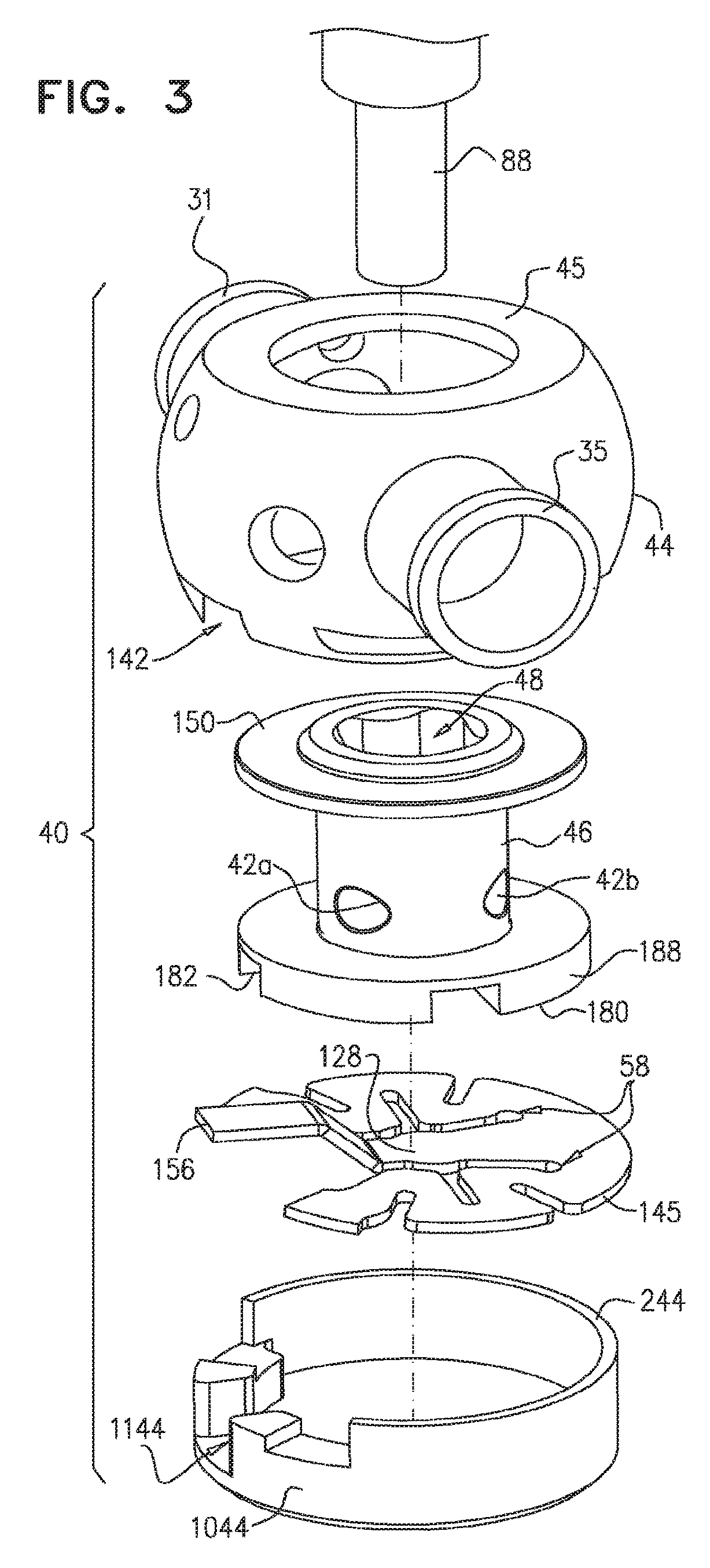
In some applications of the present invention, apparatus is provided comprising an implant structure comprising an adjustable annuloplasty ring structure coupled to at least first and second adjusting mechanisms, each comprising a respective rotatable structure. At least a portion of the annuloplasty ring structure comprises a flexible, longitudinally-compressible segment (e.g., coiled structures, stent-like struts, and/or a braided mesh). The annuloplasty structure is shaped to define a flexible, tubular body portion that is shaped so as to define a lumen thereof that houses at least one flexible longitudinal contracting member. The at least one flexible longitudinal contracting member is coupled to the first adjusting mechanism at a first portion of the flexible longitudinal contracting member. A second portion of the flexible longitudinal contracting member is coupled to a portion of the tubular body portion. The first adjusting mechanism is configured to adjust a perimeter of the annuloplasty ring structure by adjusting a degree of tension of the flexible member housed within the lumen of the annuloplasty structure. For example, the first adjusting mechanism is configured to contract the ring structure in response to rotation in a first rotational direction of the rotational structure of the first adjusting mechanism. The first adjusting mechanism is typically aligned with the tubular body portion.
Typically, the annuloplasty structure is configured to be implanted along a native annulus of an atrioventricular valve of a patient.
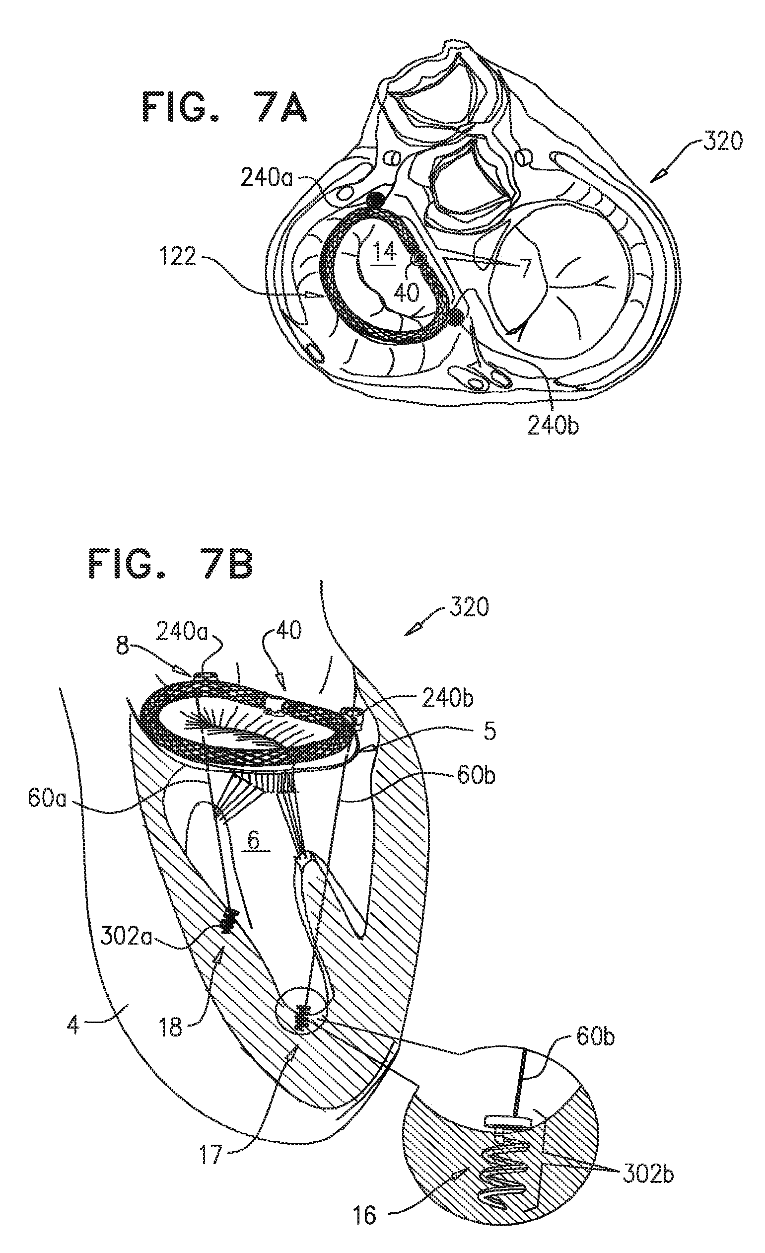
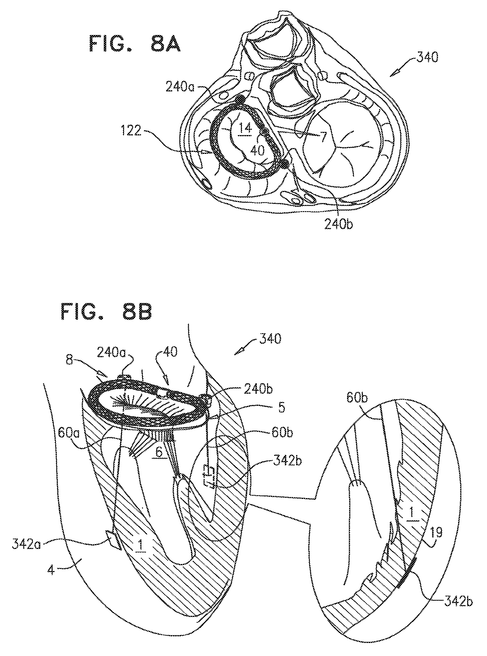
For some applications of the present invention, the second adjusting mechanism is coupled to an outer surface of the tubular body portion. The second adjusting mechanism is coupled to a first portion of a flexible longitudinal tension member. The flexible longitudinal tension member is configured to pass from the annuloplasty ring structure on the annulus of the valve of and into a ventricle. A second portion of the flexible longitudinal tension member is coupled to a tissue-engaging element configured to engage cardiac tissue in a vicinity of the ventricle (e.g., a portion of papillary muscle tissue, a portion of tissue of an inner wall of the ventricle, or a portion of tissue of an outer wall of the ventricle). For some applications, the tissue-engaging element comprises a sharp portion for penetrating the cardiac tissue. For some applications, the tissue-engaging element comprises a planar element abutting against tissue of the patient. Typically, the second portion of the flexible longitudinal tension member is configured to be coupled to a papillary muscle of the patient. The second adjusting mechanism is configured to adjust a degree of tension of the flexible longitudinal tension member in a manner sufficient to (a) adjust a position of the papillary muscle, (b) adjust a degree of distension of the ventricular wall, and/or (c) have the flexible longitudinal tension member function as an artificial chordae tendineae. For applications in which the position of the papillary muscle is adjusted such positioning typically provides therapy to the patient.
For some applications of the present invention, an annuloplasty ring structure comprises two or more adjusting mechanisms configured to shape the annuloplasty ring structure into a desired shape. For example, the two or more adjusting mechanisms function, upon actuation thereof, to form the adjustable ring into a saddle shape. Alternatively or additionally, the two or more adjusting mechanisms function, upon actuation thereof, to draw together opposing portions of the ring.
Typically, the annuloplasty ring structures described herein, the adjusting mechanisms, and the flexible longitudinal members are advanced and implanted in an open-heart procedure. For some applications, devices described herein may be implanted using a minimally-invasive or percutaneous transcatheter procedure.
Methods for delivery and use of the invention are also described.
There is therefore provided, in accordance with an application of the present invention, apparatus for use with a native valve of a heart of a patient, the native valve having a valve annulus, and the heart having a ventricle, the apparatus including:
an annuloplasty structure, shaped to define a perimeter, and configured to be disposed at the annulus of the native valve of the patient;
a first adjusting mechanism, coupled to the annuloplasty structure, and configured to adjust the perimeter of the annuloplasty structure;
at least one longitudinal flexible member, having a first end portion, and a second end portion that is configured to be coupled to tissue of the ventricle of the heart of the patient; and
at least a second adjusting mechanism: coupled to the annuloplasty structure such that the second adjusting mechanism is slidable around at least part of the perimeter of the annuloplasty structure, coupled to the first end portion of the at least one longitudinal flexible member, and configured to adjust a distance between the second adjusting mechanism and the second end portion of the at least one longitudinal flexible member.
In an application:
the annuloplasty structure is configured to be implanted at an annulus of a mitral valve of the patient,
the at least second adjusting mechanism is configured to be coupled to a location along the annulus, in a vicinity of a fibrous trigone adjacent to the mitral valve.
In an application, the apparatus further includes a plurality of sutures, each suture of the plurality of sutures being configured to be fastened to a respective location along a circumference of an annulus of a mitral valve of the patient, the plurality of sutures being configured to facilitate advancement of the annuloplasty structure toward the annulus.
In an application, the annuloplasty structure includes a coiled structure having a lumen.
In an application, the annuloplasty structure includes a partial annuloplasty ring.
In an application, the annuloplasty structure includes a full annuloplasty ring.
In an application, the annuloplasty structure is coated with polytetrafluoroethylene.
In an application, the annuloplasty structure has a first end and a second end, and a longitudinal axis therebetween, and the second adjusting mechanism is movable along the longitudinal axis of the annuloplasty structure.
In an application, the annuloplasty structure includes a body portion that defines a lumen therethrough, and the annuloplasty structure further includes a flexible longitudinal contracting member, having a first end portion, a second end portion, and a middle portion between the first and second end portions, at least one of the end portions being coupled to the first adjusting mechanism, and the middle portion being disposed within the lumen of the body portion.
In an application, the first adjusting mechanism is configured to reversibly adjust the perimeter of the annuloplasty structure, and the second adjusting mechanism is configured to reversibly adjust the distance.
In an application, the second adjusting mechanism is configured to adjust the distance between the second adjusting mechanism and the second end portion of the at least one longitudinal flexible member, independently of the adjusting of the perimeter of the annuloplasty structure by the first adjusting mechanism.
In an application:
the at least one longitudinal flexible member includes a first longitudinal flexible member and a second longitudinal flexible member, the first and second longitudinal members each having a first end portion and a second end portion, the second portion of the first longitudinal flexible member being configured to be coupled to a first portion of the tissue, and the second portion of the second longitudinal flexible member being configured to be coupled to a second portion of the tissue,
the second adjusting mechanism is coupled to the first end portion of the first longitudinal flexible member, and is configured to adjust a distance between the second adjusting mechanism and the second end portion of the first longitudinal flexible member,
the apparatus further includes a third adjusting mechanism, coupled to the annuloplasty structure and to the first end portion of the second longitudinal flexible member, and is configured to adjust a distance between the third adjusting mechanism and the second end portion of the second longitudinal flexible member.
In an application:
at least one selected from the group consisting of the first portion of the tissue and the second portion of the tissue, includes tissue of a papillary muscle of the patient, and
at least one selected from the group consisting of the second adjusting mechanism and the third adjusting mechanism, is configured to adjust a distance between the papillary muscle and the annuloplasty structure.
In an application, the third adjusting mechanism is configured to adjust the distance between the third adjusting mechanism and the second end portion of the second longitudinal flexible member, independently of the adjustment, by the second adjusting mechanism, of the distance between the second adjusting mechanism and the second end portion of the first longitudinal flexible member.
In an application, the first adjusting mechanism includes a first rotatable adjusting mechanism, and the second adjusting mechanism includes a second rotatable adjusting mechanism.
In an application, the first rotatable adjusting mechanism and the second rotatable adjusting mechanism are both rotatable bidirectionally.
In an application, the second rotatable adjusting mechanism includes a spool, and the spool is configured to pull the tissue toward the annuloplasty structure, via the longitudinal flexible member, responsively to rotation of the spool.
In an application, the apparatus further includes a rotation tool, configured to rotate the first rotatable adjusting mechanism.
In an application, the rotation tool includes an elongate rotation tool, configured to extend from outside the patient, to the first rotatable adjusting mechanism.
In an application, the rotation tool is configured to facilitate adjustment of the first adjusting mechanism while the heart of the patient is beating.
In an application, the rotation tool includes a first rotation tool, and the apparatus further includes a second rotation tool, configured to rotate the second rotatable adjusting mechanism.
In an application, at least the first adjusting mechanism includes a locking mechanism:
having an unlocked state in which the first adjusting mechanism is adjustable, having
having a locked state in which the locking mechanism inhibits adjustment of the first adjusting mechanism, and
configured to be intracorporeally moved from the locked state to the unlocked state.
In an application, the first rotation tool is configured to intracorporeally move the first rotatable adjusting mechanism into the unlocked configuration thereof.
In an application, the tissue includes papillary muscle tissue of the patient, and apparatus is configured to relocate the papillary muscle tissue, by pulling the papillary muscle tissue toward the annuloplasty structure.
In an application:
the annuloplasty structure is configured to be implanted at an annulus of a mitral valve of the patient, and
the longitudinal flexible member is configured to relocate the papillary muscle tissue, in response to the pulling by the adjusting mechanism.
In an application, the longitudinal flexible member is configured to perform a therapy by relocating the patient's papillary muscle tissue.
In an application, the annuloplasty structure is configured to be implanted at an annulus of a mitral valve of the patient, and the apparatus is configured to be transcatheterally advanced toward the annulus.
In an application, the apparatus is configured to be transluminally advanced toward the annulus.
In an application, the second end portion of the longitudinal flexible member includes a tissue-coupling element.
In an application, the tissue-coupling element includes an anchor having at least one sharp portion.
There is further provided, in accordance with an application of the present invention, apparatus for use with a native valve of a heart of a patient, the native valve having a valve annulus, and the heart having a ventricle, the apparatus including:
an annuloplasty structure, shaped to define a perimeter, and configured to be disposed at the annulus of the native valve of the patient;
a first adjusting mechanism, coupled to the annuloplasty structure, and configured to reversibly adjust the perimeter of the annuloplasty structure;
at least one longitudinal flexible member, having a first end portion, and a second end portion that is configured to be coupled to tissue of the ventricle of the heart of the patient; and
at least a second adjusting mechanism, coupled to the annuloplasty structure and to the first end portion of the at least one longitudinal flexible member, and configured to reversibly adjust a distance between the second adjusting mechanism and the second end portion of the at least one longitudinal flexible member.
In an application, the annuloplasty structure has a first end and a second end, and a longitudinal axis therebetween, and the second adjusting mechanism is movable along the longitudinal axis of the annuloplasty structure.
In an application, the annuloplasty structure includes a body portion that defines a lumen therethrough, and the annuloplasty, structure further includes a flexible longitudinal contracting member, having a first end portion, a second end portion, and a middle portion between the first and second end portions, at least one of the end portions being coupled to the first adjusting mechanism, and the middle portion being disposed within the lumen of the body portion.
In an application, the first adjusting mechanism is movably coupled to the annuloplasty structure.
In an application, the annuloplasty structure includes a partial annuloplasty ring.
In an application, the annuloplasty structure includes a full annuloplasty ring.
In an application, the annuloplasty structure is coated with polytetrafluoroethylene.
In an application:
the annuloplasty structure is configured to be implanted at an annulus of a mitral valve of the patient,
the at least second adjusting mechanism is configured to be coupled to a location along the annulus, in a vicinity of a fibrous trigone adjacent to the mitral valve.
In an application, the apparatus further includes a plurality of sutures, each suture of the plurality of sutures being configured to be fastened to a respective location along a circumference of an annulus of a mitral valve of the patient, the plurality of sutures being configured to facilitate advancement of the annuloplasty structure toward the annulus.
In an application, the annuloplasty structure includes a coiled structure having a lumen.
In an application, the second adjusting mechanism is configured to reversibly adjust the distance between the second adjusting mechanism and the second end portion of the at least one longitudinal flexible member, independently of the reversible adjusting of the perimeter of the annuloplasty structure by the first adjusting mechanism.
In an application:
the at least one longitudinal flexible member includes a first longitudinal flexible member and a second longitudinal flexible member, the first and second longitudinal members each having a first end portion and a second end portion, the second portion of the first longitudinal flexible member being configured to be coupled to a first portion of the tissue, and the second portion of the second longitudinal flexible member being configured to be coupled to a second portion of the tissue,
the second adjusting mechanism is coupled to the first end portion of the first longitudinal flexible member, and is configured to reversibly adjust a distance between the second adjusting mechanism and the second end portion of the first longitudinal flexible member,
the apparatus further includes a third adjusting mechanism, coupled to the annuloplasty structure and to the first end portion of the second longitudinal flexible member, and is configured to reversibly adjust a distance between the third adjusting mechanism and the second end portion of the second longitudinal flexible member.
In an application:
at least one selected from the group consisting of the first portion of the tissue and the second portion of the tissue, includes tissue of a papillary muscle of the patient, and
at least one selected from the group consisting of the second adjusting mechanism and the third adjusting mechanism, is configured to reversibly adjust a distance between the papillary muscle and the annuloplasty structure.
In an application, the third adjusting mechanism is configured to reversibly adjust the distance between the third adjusting mechanism and the second end portion of the second longitudinal flexible member, independently of the reversible adjustment, by the second adjusting mechanism, of the distance between the second adjusting mechanism and the second end portion of the first longitudinal flexible member.
In an application, the first adjusting mechanism includes a first rotatable adjusting mechanism, and the second adjusting mechanism includes a second rotatable adjusting mechanism.
In an application, the first rotatable adjusting mechanism and the second rotatable adjusting mechanism are both rotatable bidirectionally.
In an application, the second rotatable adjusting mechanism includes a spool, and the spool is configured to pull the tissue toward the annuloplasty structure, via the longitudinal flexible member, responsively to rotation of the spool.
In an application, the apparatus further includes a rotation tool, configured to rotate the first rotatable adjusting mechanism.
In an application, the rotation tool includes an elongate rotation tool, configured to extend from outside the patient, to the first rotatable adjusting mechanism.
In an application, the rotation tool is configured to facilitate reversible adjustment of the first adjusting mechanism while the heart of the patient is beating.
In an application, the rotation tool includes a first rotation tool, and the apparatus further includes a second rotation tool, configured to rotate the second rotatable adjusting mechanism.
In an application, at least the first adjusting mechanism includes a locking mechanism:
having an unlocked state in which the first adjusting mechanism is adjustable, having
having a locked state in which the locking mechanism inhibits adjustment of the first adjusting mechanism, and
configured to be intracorporeally moved from the locked state to the unlocked state.
In an application, the first rotation tool is configured to intracorporeally move the first rotatable adjusting mechanism into the unlocked configuration thereof.
In an application, the tissue includes papillary muscle tissue of the patient, and apparatus is configured to relocate the papillary muscle tissue, by pulling the papillary muscle tissue toward the annuloplasty structure.
In an application:
the annuloplasty structure is configured to be implanted at an annulus of a mitral valve of the patient, and
the longitudinal flexible member is configured to relocate the papillary muscle tissue, in response to the pulling by the adjusting mechanism.
In an application, the longitudinal flexible member is configured to perform a therapy by relocating the patient's papillary muscle tissue.
In an application, the annuloplasty structure is configured to be implanted at an annulus of a mitral valve of the patient, and the apparatus is configured to be transcatheterally advanced toward the annulus.
In an application, the apparatus is configured to be transluminally advanced toward the annulus.
In an application, the second end portion of the longitudinal flexible member includes a tissue-coupling element.
In an application, the tissue-coupling element includes an anchor having at least one sharp portion.
There is further provided, in accordance with an application of the present invention, a method for use with a native valve of a heart of a patient, the native valve having a valve annulus, and the heart having a ventricle, the method including:
adjusting a dimension of the annulus by rotating a first adjusting mechanism of apparatus that has been implanted in the heart of the patient;
adjusting a first distance between a first portion of tissue of the ventricle of the patient and the annulus by rotating a second adjusting mechanism of the apparatus; and
subsequently to the adjusting of the first distance, adjusting a second distance between a second portion of tissue of the ventricle of the patent and the annulus by rotating a third adjusting mechanism of the apparatus.
In an application, the annuloplasty structure has a first end and a second end, and a longitudinal axis therebetween, and sliding the second adjusting mechanism includes sliding the second adjusting mechanism along the longitudinal axis of the annuloplasty structure.
In an application:
the annuloplasty structure includes a body portion that defines a lumen therethrough, and a flexible longitudinal contracting member, having a first end portion, a second end portion, and a middle portion between the first and second end portions, at least one of the end portions being coupled to the first adjusting mechanism, and the middle portion being disposed within the lumen of the body portion, and
adjusting the perimeter of the annuloplasty structure includes adjusting a length of the flexible longitudinal contracting member between the first end portion of the flexible longitudinal contracting member and the second end portion of the flexible longitudinal contracting member.
In an application, coupling the annuloplasty structure to the annulus includes coupling the annuloplasty structure to an annulus of a mitral valve of the patient such that the at least second adjusting mechanism is disposed in a vicinity of a fibrous trigone adjacent to the mitral valve.
In an application, the method further includes receiving information indicative of blood flow of the patent, subsequently to the adjusting of the first distance, and prior to the adjusting of the second distance.
In an application, the method further includes receiving information indicative of blood flow in the heart of the patient, subsequently to the adjusting of the dimension of the annulus, and prior to the adjusting of the first distance.
In an application, at least one of: (1) the adjusting of the dimension of the annulus, (2) the adjusting of the first distance, and (3) the adjusting of the second distance, include adjusting while the heart is beating.
In an application, adjusting the first adjusting mechanism includes adjusting the first adjusting mechanism while the heart of the patient is beating.
In an application, adjusting the at least second adjusting mechanism includes adjusting the at least second adjusting mechanism while the heart of the patient is beating.
In an application, coupling the second end portion to the first portion of the tissue of the ventricle includes coupling the second end portion to tissue of a papillary muscle of the patient.
In an application, the method further includes adjusting a dimension of the annulus by adjusting the first adjusting mechanism.
In an application, the method further includes adjusting a distance between the annulus and the tissue, by adjusting the second adjusting mechanism.
In an application, the method further includes adjusting a dimension of the annulus by adjusting the first adjusting mechanism, and adjusting a distance between the annulus and the tissue independently of the adjustment of the dimension of the annulus, by adjusting the second adjusting mechanism independently of the adjustment of the first adjusting mechanism.
In an application, coupling the second end portion to the tissue includes rotating an anchor coupled to the second end portion.
In an application, at least one selected from the group consisting of adjusting the first adjusting mechanism and adjusting the second adjusting mechanism, includes rotating a rotatable adjusting mechanism.
In an application, at least one action selected from the group consisting of adjusting the first adjusting mechanism and adjusting the second adjusting mechanism, includes reversibly adjusting.
In an application, coupling the annuloplasty structure to the annulus includes coupling a partial annuloplasty ring to the annulus.
In an application, coupling the annuloplasty structure to the annulus includes coupling a full annuloplasty ring to the annulus.
In an application, at least one action selected from the group consisting of adjusting the first adjusting mechanism and adjusting the second adjusting mechanism, includes adjusting using a rotation tool.
In an application, using the rotation tool includes using an elongate rotation tool that extends from outside the patient, to the apparatus.
In an application, the method further includes, prior to adjusting, performing at least one action selected from the group consisting of unlocking the first adjustment mechanism using the rotation tool, and unlocking the second adjustment mechanism using the rotation tool.
In an application, the method further includes transcatheterally advancing the annuloplasty structure to the native valve.
In an application, transcatheterally advancing the annuloplasty structure to the native valve includes transluminally advancing the annuloplasty structure to the native valve.
In an application, the annuloplasty structure is coupled to a third adjusting mechanism that is coupled to a first end portion of a second longitudinal flexible member, and the method further includes coupling a second end portion of the second longitudinal member to a second portion of the tissue of the ventricle.
In an application, the method further includes adjusting a distance between the annuloplasty structure and the second portion of the tissue by adjusting the third adjusting mechanism.
There is further provided, in accordance with an application of the present invention, a method for use with a native valve of a heart of a patient, the native valve having a valve annulus, and the heart having a ventricle, the method including:
while the heart is beating, using apparatus that has been implanted in the heart: reducing a dimension of the annulus, reducing a distance between the annulus and at least a first portion of tissue of the ventricle of the patient, and subsequently, increasing at least one selected from the list consisting of: the dimension, and the distance; and
receiving information indicative of blood flow of the patient, the reducing and the increasing of the dimension and the distance being at least in part responsive to the receiving of the information.
In an application:
reducing the dimension includes rotating a first adjusting mechanism of the apparatus in a first rotational direction, and increasing the dimension includes rotating the first adjusting mechanism in a second, opposing rotational direction, and
reducing the distance includes rotating at least a second adjusting mechanism of the apparatus in a first rotational direction, and increasing the distance includes rotating the second adjusting mechanism in a second, opposing rotational direction.
There is further provided, in accordance with an application of the present invention, a method for use with a native valve of a heart of a patient, the native valve having a valve annulus, and the heart having a ventricle, the method including:
coupling, to the annulus, an annuloplasty structure, shaped to define a perimeter, and coupled to: a first adjusting mechanism, configured to adjust the perimeter of the annuloplasty structure, and at least a second adjusting mechanism, configured to be slidable around at least part of the perimeter of the annuloplasty structure, and coupled to a first end portion of at least one longitudinal flexible member;
coupling, to at least a first portion of tissue of the ventricle of the heart, a second end portion of the at least one longitudinal flexible member; and
sliding the second adjusting mechanism around at least part of the at least part of the perimeter of the annuloplasty structure.
In an application, the annuloplasty structure has a first end and a second end, and a longitudinal axis therebetween, and sliding the second adjusting mechanism includes sliding the second adjusting mechanism along the longitudinal axis of the annuloplasty structure.
In an application:
the annuloplasty structure includes a body portion that defines a lumen therethrough, and a flexible longitudinal contracting member, having a first end portion, a second end portion, and a middle portion between the first and second end portions, at least one of the end portions being coupled to the first adjusting mechanism, and the middle portion being disposed within the lumen of the body portion, and
adjusting the perimeter of the annuloplasty structure includes adjusting a length of the flexible longitudinal contracting member between the first end portion of the flexible longitudinal contracting member and the second end portion of the flexible longitudinal contracting member.
In an application, coupling the annuloplasty structure to the annulus includes coupling the annuloplasty structure to an annulus of a mitral valve of the patient such that the at least second adjusting mechanism is disposed in a vicinity of a fibrous trigone adjacent to the mitral valve.
In an application, coupling the annuloplasty structure to the annulus includes coupling a partial annuloplasty ring to the annulus.
In an application, coupling the annuloplasty structure to the annulus includes coupling a full annuloplasty ring to the annulus.
In an application, adjusting the first adjusting mechanism includes adjusting the first adjusting mechanism while the heart of the patient is beating.
In an application, adjusting the at least second adjusting mechanism includes adjusting the at least second adjusting mechanism while the heart of the patient is beating.
In an application, coupling the second end portion to the first portion of the tissue of the ventricle includes coupling the second end portion to tissue of a papillary muscle of the patient.
In an application, the method further includes adjusting a dimension of the annulus by adjusting the first adjusting mechanism.
In an application, the method further includes adjusting a distance between the annulus and the tissue, by adjusting the second adjusting mechanism.
In an application, the method further includes adjusting a dimension of the annulus by adjusting the first adjusting mechanism, and adjusting a distance between the annulus and the tissue independently of the adjustment of the dimension of the annulus, by adjusting the second adjusting mechanism independently of the adjustment of the first adjusting mechanism.
In an application, coupling the second end portion to the tissue includes rotating an anchor coupled to the second end portion.
In an application, at least one selected from the group consisting of adjusting the first adjusting mechanism and adjusting the second adjusting mechanism, includes rotating a rotatable adjusting mechanism.
In an application, at least one action selected from the group consisting of adjusting the first adjusting mechanism and adjusting the second adjusting mechanism, includes reversibly adjusting.
In an application, at least one action selected from the group consisting of adjusting the first adjusting mechanism and adjusting the second adjusting mechanism, includes adjusting using a rotation tool.
In an application, using the rotation tool includes using an elongate rotation tool that extends from outside the patient, to the apparatus.
In an application, the method further includes, prior to adjusting, performing at least one action selected from the group consisting of unlocking the first adjustment mechanism using the rotation tool, and unlocking the second adjustment mechanism using the rotation tool.
In an application, the method further includes transcatheterally advancing the annuloplasty structure to the native valve.
In an application, transcatheterally advancing the annuloplasty structure to the native valve includes transluminally advancing the annuloplasty structure to the native valve.
In an application, the annuloplasty structure is coupled to a third adjusting mechanism that is coupled to a first end portion of a second longitudinal flexible member, and the method further includes coupling a second end portion of the second longitudinal member to a second portion of the tissue of the ventricle.
In an application, the method further includes adjusting a distance between the annuloplasty structure and the second portion of the tissue by adjusting the third adjusting mechanism.
There is further provided, in accordance with an application of the present invention, apparatus for use with a native valve of a heart of a patient, the native valve having a valve annulus, and the heart having a ventricle, the apparatus including:
an annuloplasty structure, shaped to define a perimeter, and configured to be disposed at the annulus of the native valve of the patient;
a first adjusting mechanism, coupled to the annuloplasty structure, and configured to adjust the perimeter of the annuloplasty structure;
at least one longitudinal flexible member, having a first end portion, and a second end portion that is configured to be coupled to tissue of the ventricle of the heart of the patient; and
at least a second adjusting mechanism, coupled to the annuloplasty structure and to the first end portion of the at least one longitudinal flexible member, and configured to adjust a distance between the second adjusting mechanism and the second end portion of the at least one longitudinal flexible member,
the first and second adjusting mechanisms each including a respective locking mechanism, each locking mechanism: having an unlocked state in which the respective adjusting mechanism is adjustable, having having a locked state in which the locking mechanism inhibits adjustment of the respective adjusting mechanism, and configured to be intracorporeally moved from the locked state to the unlocked state.
In an application, the annuloplasty structure includes a partial annuloplasty ring.
In an application, the annuloplasty structure includes a full annuloplasty ring.
In an application, the annuloplasty structure is coated with polytetrafluoroethylene.
In an application:
the annuloplasty structure is configured to be implanted at an annulus of a mitral valve of the patient,
the at least second adjusting mechanism is configured to be coupled to a location along the annulus, in a vicinity of a fibrous trigone adjacent to the mitral valve.
In an application, the apparatus further includes a plurality of sutures, each suture of the plurality of sutures being configured to be fastened to a respective location along a circumference of an annulus of a mitral valve of the patient, the plurality of sutures being configured to facilitate advancement of the annuloplasty structure toward the annulus.
In an application, the annuloplasty structure includes a coiled structure having a lumen.
In an application, the annuloplasty structure has a first end and a second end, and a longitudinal axis therebetween, and the second adjusting mechanism is movable along the longitudinal axis of the annuloplasty structure.
In an application, the annuloplasty structure includes a body portion that defines a lumen therethrough, and the annuloplasty structure further includes a flexible longitudinal contracting member, having a first end portion, a second end portion, and a middle portion between the first and second end portions, at least one of the end portions being coupled to the first adjusting mechanism, and the middle portion being disposed within the lumen of the body portion.
In an application, the first adjusting mechanism is movably coupled to the annuloplasty structure.
In an application, the first adjusting mechanism is configured to reversibly adjust the perimeter of the annuloplasty structure, and the second adjusting mechanism is configured to reversibly adjust the distance.
In an application, the second adjusting mechanism is configured to adjust the distance between the second adjusting mechanism and the second end portion of the at least one longitudinal flexible member, independently of the adjusting of the perimeter of the annuloplasty structure by the first adjusting mechanism.
In an application:
the at least one longitudinal flexible member includes a first longitudinal flexible member and a second longitudinal flexible member, the first and second longitudinal members each having a first end portion and a second end portion, the second portion of the first longitudinal flexible member being configured to be coupled to a first portion of the tissue, and the second portion of the second longitudinal flexible member being configured to be coupled to a second portion of the tissue,
the second adjusting mechanism is coupled to the first end portion of the first longitudinal flexible member, and is configured to adjust a distance between the second adjusting mechanism and the second end portion of the first longitudinal flexible member,
the apparatus further includes a third adjusting mechanism, coupled to the annuloplasty structure and to the first end portion of the second longitudinal flexible member, and is configured to adjust a distance between the third adjusting mechanism and the second end portion of the second longitudinal flexible member.
In an application:
at least one selected from the group consisting of the first portion of the tissue and the second portion of the tissue, includes tissue of a papillary muscle of the patient, and
at least one selected from the group consisting of the second adjusting mechanism and the third adjusting mechanism, is configured to adjust a distance between the papillary muscle and the annuloplasty structure.
In an application, the third adjusting mechanism is configured to adjust the distance between the third adjusting mechanism and the second end portion of the second longitudinal flexible member, independently of the adjustment, by the second adjusting mechanism, of the distance between the second adjusting mechanism and the second end portion of the first longitudinal flexible member.
In an application, the first adjusting mechanism includes a first rotatable adjusting mechanism, and the second adjusting mechanism includes a second rotatable adjusting mechanism.
In an application, the first rotatable adjusting mechanism and the second rotatable adjusting mechanism are both rotatable bidirectionally.
In an application, the second rotatable adjusting mechanism includes a spool, and the spool is configured to pull the tissue toward the annuloplasty structure, via the longitudinal flexible member, responsively to rotation of the spool.
In an application, the apparatus further includes a rotation tool, configured to rotate the first rotatable adjusting mechanism.
In an application, the rotation tool includes an elongate rotation tool, configured to extend from outside the patient, to the first rotatable adjusting mechanism.
In an application, the rotation tool is configured to facilitate adjustment of the first adjusting mechanism while the heart of the patient is beating.
In an application, the rotation tool includes a first rotation tool, and the apparatus further includes a second rotation tool, configured to rotate the second rotatable adjusting mechanism.
In an application, the first rotation tool is configured to intracorporeally move the first rotatable adjusting mechanism into the unlocked configuration thereof, and the second rotation tool is configured to intracorporeally move the second rotatable adjusting mechanism into the unlocked configuration thereof.
In an application, the tissue includes papillary muscle tissue of the patient, and apparatus is configured to relocate the papillary muscle tissue, by pulling the papillary muscle tissue toward the annuloplasty structure.
In an application:
the annuloplasty structure is configured to be implanted at an annulus of a mitral valve of the patient, and
the longitudinal flexible member is configured to relocate the papillary muscle tissue, in response to the pulling by the adjusting mechanism.
In an application, the longitudinal flexible member is configured to perform a therapy by relocating the patient's papillary muscle tissue.
In an application, the annuloplasty structure is configured to be implanted at an annulus of a mitral valve of the patient, and the apparatus is configured to be transcatheterally advanced toward the annulus.
In an application, the apparatus is configured to be transluminally advanced toward the annulus.
In an application, the second end portion of the longitudinal flexible member includes a tissue-coupling element.
In an application, the tissue-coupling element includes an anchor having at least one sharp portion.
There is further provided, in accordance with an application of the present invention, apparatus for use with a native valve of a heart of a patient, the native valve having a valve annulus, and the heart having a ventricle, the apparatus including:
an annuloplasty structure, configured to be disposed at the annulus of the native valve of the patient, and shaped to define a perimeter;
a perimeter-adjusting mechanism, coupled to the annuloplasty structure, and configured to adjust the perimeter of the annuloplasty structure; and
at least two longitudinal flexible members, each longitudinal flexible member having a first end portion and a second end portion, the second end portion of each longitudinal flexible member being configured to be coupled to a respective portions of tissue of a ventricle of the heart of the patient; and
at least two length-adjusting mechanisms, each being coupled to the annuloplasty structure and to the first end portion of a respective longitudinal flexible member, and configured to adjust a distance between the length-adjusting mechanism and the second end portion of the respective longitudinal flexible member, independently of the adjustment of the perimeter of the annuloplasty structure by the first adjusting mechanism.
In an application:
the at least two length-adjusting mechanisms include a first length-adjusting mechanism and a second length-adjusting mechanism,
the at least two longitudinal flexible members include a first longitudinal flexible member and a second longitudinal flexible member,
the first length-adjusting mechanism is coupled to the first end portion of the first longitudinal flexible member, and is configured to adjust the distance between the first length-adjusting mechanism and the second end portion of the first longitudinal flexible member, and
the second length-adjusting mechanism is coupled to the first end portion of the second longitudinal flexible member, and is configured to adjust a distance between the second length-adjusting mechanism and the second end portion of the second longitudinal flexible member, independently of the adjustment, by the first length-adjusting member, of a distance between the first length-adjusting mechanism and the second end portion of the first longitudinal flexible member.
In an application, at least one of the length-adjusting mechanisms is movable around at least part of the perimeter of the annuloplasty structure.
In an application, the annuloplasty structure includes a body portion that defines a lumen therethrough, and the annuloplasty structure further includes a flexible longitudinal contracting member, having a first end portion, a second end portion, and a middle portion between the first and second end portions, at least one of the end portions being coupled to the first adjusting mechanism, and the middle portion being disposed within the lumen of the body portion.
There is further provided, in accordance with an application of the present invention, a method, including:
providing an annuloplasty structure, the annuloplasty structure including: at least one adjusting mechanism couplable to the annuloplasty structure; and at least one longitudinal flexible member;
coupling the annuloplasty structure to an annulus of a mitral valve of a patient;
coupling the longitudinal flexible member to a portion of tissue; and
relocating the portion of tissue toward the annulus by pulling the tissue with the adjusting mechanism, via the longitudinal flexible member.
In an application, coupling the longitudinal flexible member to the portion of tissue includes coupling the longitudinal flexible member to papillary muscle tissue.
In an application, the annuloplasty structure includes two adjusting mechanisms, each adjusting mechanism configured to relocate respective portions of tissue, and coupling the annuloplasty structure to the annulus includes:
coupling a first one of the adjusting mechanisms to a first location along the annulus in a vicinity of a first fibrous trigone of the mitral valve; and
coupling a second one of the adjusting mechanisms to a second location along the annulus in a vicinity of a second fibrous trigone of the mitral valve.
In an application, the method further includes transcatheterally advancing the annuloplasty structure to the annulus.
In an application, coupling the annuloplasty structure to the annulus includes coupling the annuloplasty structure to the annulus during open heart surgery.
In an application, the method further includes:
rotating, in a first direction, a rotatable adjusting mechanism that is coupled to the annuloplasty structure, by pulling a contracting member that is coupled to the rotatable structure; and
responsively, drawing first and second portions of the annuloplasty structure toward each other.
The present invention will be more fully understood from the following detailed description of embodiments thereof, taken together with the drawings, in which:
BRIEF DESCRIPTION OF THE DRAWINGS
FIG. 1 is a schematic illustration of an annuloplasty structure coupled to at least first and second adjusting mechanisms, in accordance with some applications of the present invention;
FIGS. 2A-B are schematic illustrations of an adjustable annuloplasty structure coupled to adjusting mechanisms that are slidable with respect to the adjustable annuloplasty structure, in accordance with some applications of the present invention;
FIG. 3 is a schematic illustration of an adjusting mechanism, in accordance with some applications of the present invention;
FIG. 4 is a schematic illustration of another adjusting mechanism, in accordance with some applications of the present invention;
FIG. 5 is a schematic illustration of another annuloplasty structure coupled to at least first and second adjusting mechanisms, in accordance with some applications of the present invention;
FIGS. 6A-B, 7A-B, and 8A-B are schematic illustrations of placing the implant structure of FIG. 1 in a heart of a patient, in accordance with some applications of the present invention;
FIGS. 9A-B are schematic illustrations of an implant structure comprising a septo-lateral adjusting mechanism, in accordance with some applications of the present invention;
FIGS. 10A-B are schematic illustrations an implant structure comprising a plurality of adjusting mechanisms which shape the structure into a saddle-shaped ring, in accordance with some applications of the present invention; and
FIG. 11 is a schematic illustration of a system for providing information indicative of heart function of the patient, and for facilitating adjusting the adjusting mechanisms of an annuloplasty structure in response to the information, in accordance with some applications of the invention.
DETAILED DESCRIPTION OF EMBODIMENTS
Reference is now made to FIG. 1, which is a schematic illustration of a system 120 comprising an implant structure 122 which comprises an adjustable annuloplasty ring structure that is coupled to two or more flexible-longitudinal-tension-member-adjusting-mechanisms 240 (e.g., flexible-longitudinal-tension-member-adjusting-mechanisms 240a and 240b), in accordance with some applications of the present invention. For some applications, as shown, the annuloplasty ring structure comprises a full annuloplasty ring. Adjusting mechanisms 240a and 240b typically comprise rotatable structures (e.g., spools, as described hereinbelow) which are coupled to respective first portions of flexible longitudinal tension members 60a and 60b. When system, 120 is implanted in the heart of the patient, implant structure 122 is configured to be implanted at an annulus of a native valve of a patient (e.g., an atrioventricular valve such as the mitral valve or the tricuspid valve). Tension members 60a and 60b are configured to extend toward the ventricle of the heart of the patient by passing between the leaflets of the valve or by passing through tissue of the annulus or commissures of the valve. Respective second end portions of tension members 60a and 60b are configured to be coupled to respective portions of cardiac tissue which are in the vicinity of the ventricle of the heart (e.g., portions of papillary muscle, portions of tissue at the base of the papillary muscle, portions of tissue in a vicinity of the apex, portions of tissue of an inner wall of the ventricle, and/or portions of tissue of an outer wall of the ventricle). Rotation of the rotatable structures of mechanisms 240a and 240b in a first rotational direction pulls tight the respective tension members 60a and 60b in order to draw the portions of cardiac tissue toward implant structure 122 (i.e., by reducing a distance between each mechanism 240 and the second end portion of the respective tension member 60). Rotation of the rotatable structures in a second, opposing, rotational direction loosens the respective tension members. For some applications of the present invention, system 120 functions to repair and/or effect remodeling of the portions of cardiac tissue, remodeling of the papillary muscles, and/or remodeling of a heart wall of the ventricle to treat distension. For some applications, tension members function as artificial chordae tendineae.
Flexible tension members 60a and 60b comprise a wire, a ribbon, a rope, or a band, comprising a flexible metal. Typically, flexible tension members 60a and 60b comprise a flexible and/or superelastic material, e.g., nitinol, polyester, stainless steel, or cobalt chrome. In some applications of the present invention, flexible tension members 60a and 60b each comprise a braided polyester suture (e.g., Ti-Cron.TM.). In some applications of the present invention, flexible contracting members 60a and 60b are coated with polytetrafluoroethylene (PTFE). In some applications of the present invention, flexible tension member 60a and 60b each comprise a plurality of wires that are intertwined to form a rope structure.
Typically, but not necessarily, each of adjusting mechanisms 240a and 240b is coupled to a respective longitudinal guide member 86a and 86b. Distal end portions of each guide member 86a and 86b are coupled to respective portions of mechanisms 240a and 240b and facilitate guiding along members 86a and 86b of a rotational tool toward the rotatable structures of mechanisms 240a and 240b.
The annuloplasty structure of implant structure 122 is shaped to define a flexible, tubular body portion 24 that is shaped so as to define a lumen along a longitudinal axis of structure 122 that houses at least part of at least one flexible longitudinal contracting member 30 (e.g., a middle portion of member 30). At least a portion, e.g., the entirety, of body portion 24 comprises a compressible material (e.g., a coiled element 12), as shown by way of illustration and not limitation. For example, body portion 24 may comprise stent-like struts, or a braided mesh (independently of coiled portion 12). Typically, coiled element 12 is surrounded by a braided mesh 10.
Typically, body portion 24 comprises a flexible biocompatible material, e.g., nitinol, stainless steel, platinum iridium, titanium, expanded polytetrafluoroethylene (ePTFE), or cobalt chrome. In some applications of the present invention, body portion 24 is coated with PTFE (Polytetrafluoroethylene). In other applications of the present invention, body portion 24 comprises accordion-like compressible structures which facilitate proper cinching of the annulus when structure 122 is contracted. Body portion 24, when compressed, e.g., typically along a longitudinal axis of structure 122, enables portions of annuloplasty structure 122 to contract and independently conform to the configuration of the annulus of the mitral valve of a given subject. Thus, the compressible element of body portion 24 facilitates contraction of the annulus in response to contraction of structure 122.
The annuloplasty structure of implant structure 122 comprises a flexible-longitudinal-contracting-member-adjusting-mechanism 40 disposed within a housing 44 and coupled to contracting member 30 (as described hereinbelow with reference to FIG. 3). Adjusting mechanism 40 is configured to adjust a degree of tension of contracting member 30 in order to adjust a perimeter of implant structure 122. Adjusting mechanism 40 thereby acts as a perimeter-adjusting mechanism. Housing 44 of adjusting mechanism 40 is shaped so as to define first and second coupling members 31 and 35 (shown in FIG. 3). Body portion 24 has first and second ends 21 and 23 which are coupled to first and second coupling members 31 and 35, and thereby to adjusting mechanism 40, in order to create a full annuloplasty ring. Thus, adjusting mechanism 40 is aligned with body portion 24 along the longitudinal axis thereof.
Adjusting mechanisms 240a and 240b are coupled to an outer surface of body portion 24, as shown. Typically, mechanisms 240a and 240b are coupled via sutures or any other mechanical coupling, as described hereinbelow with reference to FIGS. 2A-B. Typically, for applications in which structure 122 is implanted on the annulus of a mitral valve, adjusting mechanism 240a is coupled to a portion of the annuloplasty structure in a vicinity thereof that is configured to be placed on or near a left fibrous trigone of the annulus of the mitral valve of the patient, and adjusting mechanism 240b is coupled to a portion of the annuloplasty structure in a vicinity thereof that is configured to be placed on or near a right fibrous trigone of the annulus of the mitral valve of the patient.
Flexible contracting member 30 comprises a wire, a ribbon, a rope, or a band, comprising a flexible metal. Flexible contracting member 30 is coupled at a first end portion thereof to flexible-longitudinal-contracting-member-adjusting-mechanism 40 which is coupled to a first end 21 of body portion 24. A second end portion of flexible contracting member 30 is coupled to a second end 23 of body portion 24. Typically, during a resting state of structure 122, flexible contracting member 30 (e.g., the middle portion thereof) is disposed in parallel with the longitudinal axis of structure 122. Flexible member 30, for some applications does not comprise a continuous band that runs through the entire lumen of the annuloplasty devices described herein, and flexible member 30 has at least one free end portion.
Typically, flexible contracting member 30 comprises a wire, a cable, or a rope, and taken together with the compressible element of body portion 24 and the braided mesh surrounding body portion 24, imparts flexibility to the entire annuloplasty structure.
Typically, flexible contracting member 30 comprises a flexible and/or superelastic material, e.g., nitinol, polyester, stainless steel, or cobalt chrome, and is configured to reside chronically within structure 122. In some applications of the present invention, flexible contracting member 30 comprises a braided polyester suture (e.g., Ti-Cron.TM.). In some applications of the present invention, flexible contracting member 30 is coated with polytetrafluoroethylene (PTFE). In some applications of the present invention, flexible contracting member 30 comprises a plurality of wires that are intertwined to form a rope structure.
Adjusting mechanism 40 comprises a housing 44 which houses a rotatable structure, or a spool 46. The rotatable structure is rotatable in first and second opposing rotational directions with respect to housing 44 so as to expand and contract the annuloplasty structure, respectively. Spool 46 has a cylindrical body that is disposed perpendicularly with respect to the longitudinal axis of structure 122. As shown in FIG. 3, spool 46 is shaped to provide at least one hole 42 for coupling of the first end portion of flexible contracting member 30 thereto and, thereby, to adjusting mechanism 40. For some applications of the present invention, spool 46 is shaped to define one or more holes 42 configured for looping a portion of contracting member 30 therethrough, as described hereinbelow. In such an application: (a) a middle portion, which defines the first end portion, of contracting member 30 is coupled to spool 46 by being looped through one or more holes 42, (b) first and second portions that extend from the first end portion looped through spool 46 extend toward second end 23 of structure body portion 24, and (c) first and second free ends of contracting member 30 are coupled to second end 23 of body portion 24 and define a second end portion of contracting member 30.
It is to be noted that for some applications of the present invention, flexible contracting member 30 may be coupled at both its first and second end portions, e.g., first and second ends, to spool 46 of adjusting mechanism 40. In some applications of the present invention, a first end of flexible contracting member 30 is coupled to spool 46 while a second end of flexible contracting member 30 is coupled to the housing which houses spool 46. For some applications, contracting member 30 comprises a continuous band that is looped through a portion of spool 46.
As shown, the annuloplasty structure of implant structure 122 defines a substantially ring-shaped configuration, e.g., a "D"-shaped configuration, as shown, which conforms to the shape of the annulus of a mitral valve of the subject. For applications in which structure 122 is implanted at a tricuspid valve of the patient, the annuloplasty structure assumes a shape suitable to fit the tricuspid valve (e.g., a substantially oval shape).
Prior to contracting of structure 122, the compressible element of body portion 24 is relaxed and structure 122 defines a first perimeter thereof. Structure 122 provides portions 49 which are flexible and less longitudinally compressible, e.g., not longitudinally compressible, with respect to the compressible element of body portion 24. Portions 49 are configured to be disposed along the fibrous portion of the annulus that is between the fibrous trigones of the mitral valve of the heart when structure 122 is anchored, sutured, fastened or otherwise coupled to the annulus of the mitral valve. Portions 49 impart rigidity to structure 122 in the portion thereof that is disposed between the fibrous trigones such that structure 122 better mimics the conformation and functionality of the mitral valve. That is, during rotation of spool 46, and the concurrent contraction or expansion of structure 122, energy is not expended on contracting or expanding portions 49. As shown, coiled portion 12 of body portion 24 has a very small pitch compared to coiled portion 12 in the remaining portions of the annuloplasty structure. For some applications, portions 49 comprise a material that is arranged in a configuration in which portions 49 are more rigid.
Typically, both portions 49 have a combined length of 10-50 mm.
Thus, the annuloplasty structure of implant structure 122 defines a compressible portion and a non-compressible portion. Typically, a radius of curvature at a center of the compressible portion of body portion 24 is smaller than a radius of curvature at a center of less-compressible portions 49, when no external force is applied to the annuloplasty structure.
It is to be noted that the compressible element of body portion 24 and less-compressible portions 49 comprise flexible coiled elements by way of illustration and not limitation. For example, the compressible element of body portion 24 and less-compressible portions 49 may comprise stent-like struts, or a braided mesh. In either configuration, portions 49 are chronically longitudinally compressed in a resting state of structure 122.
It is to be noted that, structure 122 may be provided independently of less-compressible portions 49. In such applications of the present invention, the annuloplasty structure comprises a fully compressible ring, e.g., a continuous ring.
It is to be noted that housing 44 (and mechanism 40) may be disposed at any suitable location along structure 122, and not only in between portions 49 (e.g., in a portion of the annuloplasty structure designated for implantation at an anterior portion of the mitral valve). For example, housing 44 may be coupled to the section of body portion 24 that is compressible. In some applications of the present invention, housing 44 may be disposed in the middle of the section of body portion 24 that is compressible. In some applications of the present invention, housing 44 may be coupled to structure 122 at an interface between a first end of portion 49 and the section of body portion 24 that is compressible. In such applications of the present invention, portions 49 may be combined to form one substantially less-compressible portion having first and second ends that are in series with the compressible portion of body portion 24. For some applications, a plurality of housings and adjusting mechanisms 40 described herein may be coupled to the annuloplasty structure. Each adjusting mechanism 40 may be coupled to a respective contracting member 30 which controls a respective portion of the annuloplasty structure.
Typically, the annuloplasty structure of implant structure 122 is delivered to the annulus of the valve using an elongate tool 50 that is reversibly coupled to adjusting mechanism 40 of structure 122. Tool 50 comprises an elongate body portion 52 which houses a flexible rod that is coupled at a distal end thereof to a screwdriver head. The screwdriver head is configured to be disposed within the channel of spool 46. Typically, the rod functions as a screwdriver which applies force to the screwdriver head in order to rotate spool 46, and thereby facilitate contraction of structure 122.
For some applications, the screwdriver head comprises force applicator 88, as described hereinabove with reference to FIG. 3. For other applications, force applicator 88 is coupled to an elongate member that is removable from spool 46 by tool 50.
(In this context, in the specification and in the claims, "proximal" means closer to the orifice through which the implant structure is originally placed into the body of the patient, along the path of delivery of the implant structure, and "distal" means further from this orifice along the path of delivery of the implant structure.)
In some applications of the present invention, the annuloplasty structure is wrapped around an annuloplasty sizer 121. Once wrapped around sizer 121, the flexible member is contracted by tool 50 such that the annuloplasty structure hugs and is stabilized around sizer 121. Sizer is coupled to a shaft 123. (It is to be noted that, for clarity of illustration, tool 50, body portion 52, and shaft 123 are not shown in the enlarged portion of FIG. 1.) Tool 50, shaft 123, and sizer 121 help position implant structure 122 along the annulus and stabilize the structure as it is being contracted. Once the structure 122 is positioned at the annulus, structure is sutured, anchored, or otherwise coupled to the annulus. Following the coupling of structure 122 to the annulus, sizer 121 is decoupled from structure 122.
Subsequently, tool 50 facilitates the contraction and/or expansion of the annuloplasty structure of implant structure 122 in order to adjust a dimension of the valve annulus. The distal portion of tool 50 comprises a tool housing which surrounds a portion of housing 44 of mechanism 40, and stabilizes housing 44 during the advancement and contraction and/or expansion of structure 122.
Reference is now made to FIGS. 2A-B, which are schematic illustrations of a system 130, which is similar to system 120, as described hereinabove with reference to FIG. 1, with the exception that adjusting mechanisms 240a and 240b are coupled to body portion 24 of the annuloplasty structure of implant structure 122 by a slide-facilitating ring 241, in accordance with some applications of the present invention. Housing 248 of each adjusting mechanism 240 is coupled to ring 241, as shown in FIG. 2A. Ring 241 surrounds a portion of the outer surface of body portion 24 and enables mechanism 240 to slide along the outer surface of body portion 24 to any suitable position along the annuloplasty structure of implant structure 122 (as indicated by the arrow and the adjusting mechanism 240 shown in phantom in FIG. 2B).
It is to be noted that adjusting mechanisms 240 are shown in FIGS. 2A-B without guide members 86 (described hereinabove with reference to FIG. 1).
Reference is now made to FIG. 3, which is a schematic illustration showing a relationship among individual components of flexible-longitudinal-contracting-member-adjusting-mechanism 40, in accordance with some applications of the present invention. Adjusting mechanism 40 is shown as comprising spool housing 44 which defines an upper surface 45 and a recess 142 at a lower surface thereof. A spool 46 is configured to be disposed within housing 44 and defines an upper surface 150, a lower surface 180, and a cylindrical body portion disposed vertically between surfaces 150 and 180. The cylindrical body portion of spool 46 is shaped so as to define a channel which extends from a first opening at upper surface 150 to a second opening at lower surface 180.
Lower surface 180 of spool 46 is shaped to define one or more (e.g., a plurality, as shown) of recesses 182 which define structural barrier portions 188 of lower surface 180. It is to be noted that any suitable number of recesses 182 may be provided, e.g., between 1 and 10 recesses. For some applications, recesses 182 are provided circumferentially with respect to lower surface 180 of spool 46.
Typically, spool 46 comprises a locking mechanism 145. For some applications, locking mechanism 145 is coupled, e.g., welded, at least in part to a lower surface of spool housing 44. Typically, locking mechanism 145 defines a mechanical element having a planar surface that defines slits 58. The surface of locking mechanism 145 may also be curved, and not planar. Locking mechanism 145 is shaped to provide a protrusion 156 which projects out of a plane defined by the planar surface of the mechanical element. The slits define a depressible portion 128 of locking mechanism 145 that is disposed in communication with and extends toward protrusion 156.
In a resting state of locking mechanism 145 (i.e., a locked state of spool 46), protrusion 156 is disposed within a recess 182 of spool 46. Additionally, in the locked state of spool 46, protrusion 156 is disposed within recess 142 of housing 44.
Depressible portion 128 is aligned with the opening at lower surface 180 of spool 46 and is moveable in response to a force applied thereto by a distal force applicator 88. That is, distal force applicator 88 is configured to be disposed within the channel of spool 46. A distal end of applicator 88 is configured to push on depressible portion 128 in order to move depressible portion 128 downward so as to disengage protrusion 156 from within a recess 182 of spool and to unlock spool 46 from locking mechanism 145.
It is to be noted that the planar, mechanical element of locking mechanism 145 is shown by way of illustration and not limitation and that any suitable mechanical element having or lacking a planar surface but shaped to define at least one protrusion may be used together with locking mechanism 145.
A cap 1044 is provided that is shaped so as to define a planar surface and an annular wall having an upper surface 244 that is coupled to, e.g., welded to, the lower surface of spool housing 44. The annular wall of cap 1044 is shaped so as to define a recessed portion 1144 of cap 1044 that is in alignment with recess 142 of spool housing 44. Locking mechanism 145 is disposed between lower surface 180 of spool 46 and the planar surface of cap 1044.
In an unlocked state of adjusting mechanism 40, protrusion 156 of locking mechanism 145 is disposed within recessed portion 1144 of cap 1044. In the unlocked state, force applicator 88 extends through spool 46 and pushes against depressible portion 128 of locking mechanism 145. The depressible portion is thus pressed downward, freeing protrusion 156 from within a recess 182 defined by structural barrier portions 188 of the lower portion of spool 46. Additionally, protrusion 156 is freed from within the recessed portion of spool housing 44. As a result, contracting mechanism 40 is unlocked, and spool 46 may be rotated with respect to spool housing 44.
Cap 1044 functions to restrict distal pushing of depressible portion 128 beyond a desired distance so as to inhibit deformation of locking mechanism 145. For applications in which adjusting mechanism 40 is implanted in heart tissue, cap 1044 also provides an interface between adjusting mechanism 40 and the heart tissue. This prevents interference of heart tissue on adjusting mechanism 40 during the locking and unlocking thereof. Additionally, cap 1044 prevents damage to heart tissue by depressible portion 128 as it is pushed downward.
Spool 46 is shaped so as to define a driving interface 48. A rotation tool (not shown) is configured to slide engage spool 46 at interface 48. The rotation tool is configured to rotate spool 46 by applying rotational force to spool 46 at interface 48. For some applications, a friction-reducing ring (not shown in FIG. 3, but shown in FIG. 4) is disposed between upper surface 150 of spool 46 and the inner surface of upper surface 45 of spool housing 44.
For some applications the rotation tool used to rotate spool 46 may be shaped to provide distal force applicator 88 configured to unlock spool 46 from locking mechanism 145. When unlocked, spool 46 may be bidirectionally rotated.
Following rotation of spool 46 such that contraction member 30 is contracted sufficiently to adjust the perimeter of the annuloplasty structure to a desired dimension so as to contract the annulus of the valve, spool 46 is then locked in place so as to restrict rotation of spool 46. Force applicator 88 is removed from within the channel of spool 46, and thereby, depressible portion 128 returns to its resting state. As depressible portion 128 returns to its resting state, protrusion 156 is introduced within one of the plurality of recesses 182 of lower surface 180 of spool 46 and within recess 142 of housing 44, and thereby restricts rotation of spool 46.
Reference is now made to FIG. 4, which is a schematic illustration showing a relationship among individual components of flexible-longitudinal-tension-member-adjusting-mechanism 240, in accordance with some applications of the present invention. Adjusting mechanism 240 is shown as comprising spool housing 248 which defines an upper surface 160 and a lower surface 176 defining a recessed portion (as described with regard to recess 142 with reference to FIG. 3). A spool 246 is configured to be disposed within housing 248 and defines an upper surface 178, a lower surface 180, and a cylindrical body portion disposed vertically between surfaces 178 and 180. The cylindrical body portion of spool 246 is shaped so as to define a channel which extends from a first opening at upper surface 178 to a second opening at lower surface 180.
Lower surface 180 of spool 246 is shaped to define one or more (e.g., a plurality, as shown) of recesses 182 which define structural barrier portions 188 of lower surface 180. It is to be noted that any suitable number of recesses 182 may be provided, e.g., between 1 and 10 recesses. For some applications, recesses 182 are provided circumferentially with respect to lower surface 180 of spool 246.
Typically, spool 246 comprises a locking mechanism 145. For some applications, locking mechanism 145 is coupled, e.g., welded, at least in part to a lower surface of spool housing 248. Typically, locking mechanism 145 defines a mechanical element having a planar surface that defines slits 58. The surface of locking mechanism 145 may also be curved, and not planar. Locking mechanism 145 is shaped to provide a protrusion 156 which projects out of a plane defined by the planar surface of the mechanical element. The slits define a depressible portion 128 of locking mechanism 145 that is disposed in communication with and extends toward protrusion 156.
In a resting state of locking mechanism 145 (i.e., a locked state of spool 246), protrusion 156 is disposed within a recess 182 of spool 246. Additionally, in the locked state of spool 246, protrusion 156 is disposed within the recess of housing 248.
Depressible portion 128 is aligned with the opening at lower surface 180 of spool 246 and is moveable in response to a force applied thereto by a distal force applicator 88 that extends in a distal direction from a distal portion of longitudinal guide member 86. That is, distal force applicator 88 is configured to be disposed within the channel of spool 246. A distal end of applicator 88 is configured to push on depressible portion 128 in order to move depressible portion 128 downward so as to disengage protrusion 156 from within a recess 182 of spool and to unlock spool 246 from locking mechanism 145.
It is to be noted that the planar, mechanical element of locking mechanism 145 is shown by way of illustration and not limitation and that any suitable mechanical element having or lacking a planar surface but shaped to define at least one protrusion may be used together with locking mechanism 145.
A cap 1044 is provided that is shaped so as to define a planar surface and an annular wall having an upper surface 244 that is coupled to, e.g., welded to, lower surface 176 of spool housing 248. The annular wall of cap 1044 is shaped so as to define a recessed portion 1144 of cap 1044 that is in alignment with the recessed portion of spool housing 248. Locking mechanism 145 is disposed between lower surface 180 of spool 246 and the planar surface of cap 1044.
In an unlocked state of adjusting mechanism 240, protrusion 156 of locking mechanism 145 is disposed within recessed portion 1144 of cap 1044. In the unlocked state, force applicator 88 extends through spool 246 and pushes against depressible portion 128 of locking mechanism 145. The depressible portion is thus pressed downward, freeing protrusion 156 from within a recess 182 defined by structural barrier portions 188 of the lower portion of spool 246. Additionally, protrusion 156 is freed from within the recessed portion of spool housing 248. As a result, contracting mechanism 240 is unlocked, and spool 246 may be rotated with respect to spool housing 248.
Cap 1044 functions to restrict distal pushing of depressible portion 128 beyond a desired distance so as to inhibit deformation of locking mechanism 145. For applications in which adjusting mechanism 240 is implanted in heart tissue, cap 1044 also provides an interface between adjusting mechanism 240 and the heart tissue. This prevents interference of heart tissue on adjusting mechanism 240 during the locking and unlocking thereof. Additionally, cap 1044 prevents damage to heart tissue by depressible portion 128 as it is pushed downward.
Spool 246 is shaped so as to define a rotation-facilitating head 170. A rotation tool (not shown) is configured to slide distally along guide member 86 to engage head 170 of spool 246. The rotation tool is configured to rotate spool 246 by applying rotational force to head 170. A friction-reducing ring 172 is disposed between upper surface 178 of spool 246 and the inner surface of upper surface 160 of spool housing 248.
For some applications, as described herein, guide member 86 is not coupled to spool 246. For such applications the rotation tool used to rotate spool 246 may be shaped to provide a distal force applicator (similar to distal force applicator 88) configured to unlock spool 246 from locking mechanism 145. In the unlocked state, spool 246 may be bidirectionally rotated.
Following rotation of spool 246 such that tension member 60 is pulled sufficiently to adjust the degree of tension of member 60 so as treat tissue of the ventricle as described herein, spool 246 is then locked in place so as to restrict rotation of spool 246. Force applicator 88 is removed from within the channel of spool 246, and thereby, depressible portion 128 returns to its resting state. As depressible portion 128 returns to its resting state, protrusion 156 is introduced within one of the plurality of recesses 182 of lower surface 180 of spool 246 and within the recess of housing 248, and thereby restricts rotation of spool 246.
Spool 246 is shaped so as to provide a hole 242 or other coupling mechanism for coupling a first portion of flexible longitudinal tension member 60 to spool 246, and thereby to adjusting mechanism 240.
FIG. 5 is a schematic illustration of a system 220 comprising an implant structure 222 which comprises an adjustable annuloplasty ring structure that is coupled to two or more flexible-longitudinal-tension-member-adjusting-mechanisms 240a and 240b, as described hereinabove with reference to FIG. 1, in accordance with some applications of the present invention. For some applications, as shown, the annuloplasty ring structure comprises a partial annuloplasty ring. Adjusting mechanisms 240a and 240b typically comprise rotatable structures (e.g., spools, as described hereinbelow) which are coupled to respective first portions of flexible longitudinal tension members 60a and 60b. When system, 220 is implanted in the heart of the patient, implant structure 222 is configured to be implanted at an annulus of a native valve of a patient (e.g., an atrioventricular valve such as the mitral valve or the tricuspid valve). Tension members 60a and 60b are configured to extend toward the ventricle of the heart of the patient by passing between the leaflets of the valve or by passing through tissue of the annulus or commissures of the valve. Respective second end portions of tension members 60a and 60b are configured to be coupled to respective portions of cardiac tissue which are in the vicinity of the ventricle of the heart (e.g., portions of papillary muscle, portions of tissue at the base of the papillary muscle, portions of tissue in a vicinity of the apex, portions of tissue of an inner wall of the ventricle, and/or portions of tissue of an outer wall of the ventricle).
Rotation of the rotatable structures of mechanisms 240a and 240b in a first rotational direction pulls tight (e.g., shortens) the respective tension members 60a and 60b in order to draw the portions of cardiac tissue toward implant structure 222 (i.e., to reduce the distance between each mechanism 240 and the second end portion of the respective tension member 60). Mechanisms 240a and 240b thereby act as perimeter-adjusting mechanisms. For some applications of the present invention, system 220 functions to repair and/or effect remodeling of the portions of cardiac tissue, remodeling of the papillary muscles, and/or remodeling of a heart wall of the ventricle to treat distension. For some applications, tension members function as artificial chordae tendineae.
Flexible-longitudinal-tension-member-adjusting-mechanisms 240a and 240b, tension members 60a and 60b, contracting member 30, and flexible-longitudinal-contracting-member-adjusting-mechanism 40 shown in FIG. 4 are identical to those described hereinabove with reference to FIG. 1. For some applications, adjusting mechanisms 240a and 240b are coupled to the outer surface of body portion 224 of structure 222 by rings 241, as described hereinabove with reference to FIGS. 2A-B. The annuloplasty structure of implant structure 221 comprises a body portion 224 which is similar to body portion 24 described hereinabove with reference to FIG. 1. It is to be noted that although body portion 224 is shown as comprising only coiled portion 12, body portion 224 may comprise a braided mesh or may be surrounded by a braided mesh, as described hereinabove with reference to FIG. 1.
Adjusting mechanism 40 is coupled to a first end 221 of body portion 224. Flexible contracting member 30 is coupled at a first end portion thereof to adjusting mechanism 40. A second end portion of flexible contracting member 30 is coupled to a second end 223 of body portion 224. Typically, during the resting state, flexible contracting member 30 is disposed in parallel with the longitudinal axis of structure 222. That is, flexible member 30, for some applications does not comprise a continuous band that runs through the entire lumen of the annuloplasty devices described herein, and flexible member 30 has at least one free end portion.
Typically, first end 221 of body portion 224 is welded to coupling member 31 of a housing 344 surrounding spool 46. Housing 344 is similar to housing 44 described herein, with the exception that coupling member 35 of housing 44 is replaced with a first suture fastener 41. First suture fastener 41 is shaped to define a hole 43 for passage therethrough of a suture to suture structure 222 to tissue of the patient. Second end 223 of body portion 224 comprises a second suture fastener 37 that is shaped to define a hole 47 for passage therethrough of a suture.
Reference is now made to FIGS. 1-3 and 5. As shown in FIG. 3, spool 46 is shaped so as to provide one or more holes 42a and 42b or other coupling mechanism for coupling a first portion of flexible longitudinal contracting member 30 to spool 46, and thereby to adjusting mechanism 40. In response to a rotational force applied to spool 46 in a first rotational direction, successive portions of flexible contracting member 30 are wrapped around spool 46 in order to tighten contracting member 30. That is, during rotation of spool 46 in the first direction, successive portions of member 30 contact spool 46. As flexible contracting member 30 is wrapped around spool 46, the second end portion of member 30 is pulled toward adjusting mechanism 40. Pulling the second end of flexible contracting member 30 toward mechanism 40 pulls the respective second ends 23 of structures 122 and 222 toward the respective first ends 21 of structures 122 and 222. Responsively, the compressible element of body portion 24 is longitudinally compressed, thereby contracting structures 122 and 222.
It is to be noted that the contraction of structures 122 and 222 is reversible. That is, rotating spool 46 in a second rotational direction that opposes the first rotational direction used to contract the annuloplasty structure, unwinds a portion of flexible contracting member 30 from around spool 46. Unwinding the portion of flexible contracting member 30 from around spool 46 thus feeds the portion of flexible contracting member 30 back into the lumen of body portion 24 of respective structures 122 and 222, thereby slackening the remaining portion of flexible contracting member 30 that is disposed within the lumen of body portion 24. Responsively, the annuloplasty structure gradually relaxes and expands (i.e., with respect to its contracted state prior to the unwinding) as the compressible element of body portion 24 gradually expands.
Reference is now made to FIGS. 6A-B, which are schematic illustrations of a system 300 for repairing a mitral valve 14 and papillary muscles 2a and 2b of a heart 4 of the patient using implant structure 122, as described hereinabove with reference to FIG. 1, in accordance with some applications of the present invention. Implant structure 122 is positioned along the annulus of valve 14 and is coupled thereto using sutures, anchors, and/or any other suitable tissue-coupling element. As shown, implant 122 is positioned along the annulus in a manner in which portions 49 and mechanism 40 are disposed along the annulus at an anterior section 7 of valve 14, adjusting mechanism 240a is implanted in a vicinity of a left fibrous trigone 8 of valve 14, and adjusting mechanism 240b is implanted in a vicinity of a right fibrous trigone 5 of valve 14. Following the coupling of structure 122 to the annulus of valve 14, tension members 60a and 60b are pulled down into a ventricle 6 of heart 4 by the operating physician (e.g., using his/her hands or using a tool). For some applications, members 60a and 60b pass through an opening created in the annulus of valve 14 (e.g., by puncturing a needle therethrough). Alternatively, members 60a and 60b pass between the leaflets of valve 14. Further alternatively, members 60a and 60b pass through respective commissures of valve 14.
Respective tissue-coupling elements 302a and 302b are coupled to respective distal portions of members 60a and 60b, respectively. Elements 302a and 302b comprise helical tissue anchors by way of illustration and not limitation. That is, elements 302a and 302b may comprise any suitable tissue-engaging structure. As shown, elements 302a and 302b are configured to be coupled to tissue of respective papillary muscles 2a and 2b.
Following the coupling of structure 122 to the annulus of valve 14 and/or the coupling of tissue-engaging elements 302a and 302b, the spool of adjusting mechanism 40 is rotated in order to adjust a dimension of the annuloplasty structure of implant structure 122 and thereby to adjust a dimension of the annulus and relative positioning of the leaflets of valve 14. For example, in response to rotation of the spool of mechanism 40 in a first rotational direction thereof, the annuloplasty structure is contracted in order to contract the annulus and to draw together the leaflets of valve 14.
Following the coupling of tissue-engaging elements 302a and 302b, the spools of adjusting mechanisms 240a and 240b are rotated in order to adjust a degree of tension of tension members 60a and 60b. For example, in response to rotation of the spools of mechanisms 240a and 240b in a first rotational direction thereof, tension members 60a and 60b are pulled tight in order to pull on papillary muscles 2a and 2b.
For such applications, members 60a and 60b function to relocate and/or alter a geometry and/or spatial configuration of papillary muscles 60a and 60b. For some applications, members 60a and 60b function as artificial chordae tendineae.
For some applications, members 60a and 60b function to repair a distension of the heart wall surrounding ventricle 6.
It is to be noted that implant structure 122 and tension members 60a and 60b may be implanted using an open-heart or minimally-invasive procedure.
For some applications, whether the implant structure and tension members are implanted using an open-heart or a minimally-invasive procedure, adjustment (e.g., rotation) of mechanisms 40, 240a, and 240b is performed off-pump (e.g., while the heart is beating), using a tool to facilitate the rotation of the adjusting mechanisms (e.g., elongate tool 50, force applicator 88, or similar). For example, following an open-heart procedure, heart tissue may be closed so as to provide only a small channel through which the tool extends, such that the heart can beat without leaking. Adjustment (e.g., rotation) of the adjusting mechanisms off-pump facilitates adjustment of the valve annulus and ventricle, while monitoring heart function and/or blood flow using imaging techniques, e.g., such that the physician may adjust until optimal heart function and/or blood flow is attained. For example, the physician may advance the tool (e.g., facilitated by imaging, such as fluoroscopy and/or ultrasound), and then sequentially, and/or repeatedly adjust (e.g., rotate) mechanism 40, mechanism 240a, and mechanism 240b (e.g., facilitated by imaging, such as Doppler ultrasound, in real-time and/or between adjustments). The order in which the adjusting mechanisms are adjusted may be decided by the physician, such as in response to the blood flow monitoring.
Reference is now made to FIGS. 7A-B, which are schematic illustrations of a system 320 for repairing a mitral valve 14 and portions of tissue of ventricle 6 of a heart 4 of the patient, as described hereinabove with reference to FIGS. 6A-B, with the exception that tissue-engaging elements 302a and 302b are coupled to respective portions of tissue along an inner wall of ventricle 6, in accordance with some applications of the present invention. As shown, tissue-engaging element 302a is coupled to a portion 16 of tissue in a vicinity of an apex 17 of heart 4, and tissue-engaging element 302b is coupled to a portion 18 of tissue at a base of the papillary muscle.
For some applications, members 60a and 60b function to relocate and/or alter a geometry and/or spatial configuration of papillary muscles 60a and 60b. For other applications, members 60a and 60b function to repair a distension of the heart wall surrounding ventricle 6. For yet other applications, members 60a and 60b function as artificial chordae tendineae.
Reference is now made to FIGS. 8A-B, which are schematic illustrations of a system 340 for repairing a mitral valve 14 and portions of tissue of ventricle 6 of a heart 4 of the patient, as described hereinabove with reference to FIGS. 6A-B and 7A-B, with the exception that respective second portions of tension members 60a and 60b are configured to extend trans-myocardially to an external surface 19 of heart 4, in accordance with some applications of the present invention.
A respective tissue-engaging element is coupled to the second portion of each tension member 60a and 60b. Each tissue-engaging element comprises a respective tissue-abutting pad 342a and 342b configured to rest against respective portions of surface 19 of heart 4.
For such applications, members 60a and 60b function to repair a distension of the heart wall surrounding ventricle 6. For some applications, members 60a and 60b function to relocate and/or alter a geometry and/or spatial configuration of papillary muscles 60a and 60b.
Reference is now made to FIGS. 9A-B, which are schematic illustrations of an implant structure 400 comprising an annuloplasty ring structure as described hereinabove with reference to FIG. 1, with the exception that structure 400 comprises a proximity-adjusting-mechanism 420, in accordance with some applications of the present invention. Structure 400 defines an anterior-configured portion 402 configured for placement adjacent the anterior leaflet of the mitral valve. Additionally, structure 400 defines a posterior-configured portion 404 configured for placement adjacent the posterior leaflet of the mitral valve. For some applications, portion 402 is flexible and less longitudinally compressible than portion 404. For example, portion 402 may comprise portions 49 described hereinabove with reference to FIG. 1.
As described hereinabove, adjusting mechanism 40 is configured to adjust a dimension of structure 400 by contracting and expanding a contracting member disposed within the lumen of body portion 24.
As shown, flexible-longitudinal-contracting-member-adjusting-mechanism 40 is aligned with body portion 24 along the longitudinal axis thereof, as described hereinabove with reference to FIG. 1. Proximity-adjusting-mechanism 420 comprises any rotatable adjusting mechanism described herein (e.g., as described hereinabove with reference to FIGS. 3 and 4). Mechanism 420 comprises a housing 426 configured to surround a portion of the outer surface of body portion 24, typically surrounding a portion of body portion 24 that opposes adjusting mechanism 40. The rotatable structure of proximity-adjusting mechanism 420 is coupled to a first portion of a flexible elongate member 422. A second portion 424 of elongate member 422 is coupled to housing 44 (e.g., typically at an external surface thereof).
Typically, the rotatable structure of adjusting mechanism 420 comprises a spool. In response to rotation of the rotatable structure of adjusting mechanism 420 in a first rotational direction, successive portions of elongate member 422 are wound around the spool and pull tight the portion of elongate member 422 disposed between adjusting mechanisms 40 and 420. In response, a portion of posterior-configured portion 404 is pulled in the direction as indicated by the arrow in FIG. 9B. Thus, adjusting mechanism 420 is configured to adjust a septo-lateral dimension of structure 400 and of the annulus of the mitral valve when structure 400 is implanted at the annulus of the mitral valve in order to adjust the distance between the leaflets of the valve and to adjust opposing portions of the annulus of the mitral valve.
It is to be noted that the rotation of the rotational structure of adjusting mechanism 420 is reversible, and that following rotation of the rotatable structure in order to pull structure 400 into the configuration shown in FIG. 9B, the rotatable structure may be rotated in a second rotational direction that opposes the first rotational direction in order for structure 400 to assume the configuration shown in FIG. 9A.
It is to be noted that mechanisms 40 and 420 may be positioned at any suitable location along body portion 24 of structure 400.
As shown, the annuloplasty structure of implant structure 400 defines a substantially ring-shaped configuration, e.g., a "D"-shaped configuration, as shown, which conforms to the shape of the annulus of a mitral valve of the subject. For applications in which structure 400 is implanted at a tricuspid valve of the patient, the annuloplasty structure assumes a shape suitable to fit the tricuspid valve (e.g., a substantially oval shape).
It is to be noted that structure 400 is shown independently of flexible-longitudinal-tension-member-adjusting-mechanisms 240 and tension members 60 by way of illustration and not limitation. For some applications, structure 400 is coupled to one or more mechanisms 240.
Reference is now made to FIGS. 10A-B, which are schematic illustrations of an implant structure 500 comprising an annuloplasty ring structure configured to transition between a substantially planar configuration (FIG. 10A) and a saddle-shaped configuration (FIG. 10B) in response to rotation of two or more (e.g., three, as shown) flexible-longitudinal-contracting-member-adjusting-mechanisms 40. As shown, structure 500 comprises three adjusting mechanisms 40a, 40b, and 40c that are aligned with the body portion of structure 500 along a longitudinal axis thereof, as described hereinabove with reference to FIG. 1. Adjusting mechanisms 40a, 40b, and 40c are described hereinabove with reference to FIGS. 1 and 3. It is to be noted, however, that the adjusting mechanisms may comprise adjusting mechanisms 240, as described hereinabove with reference to FIGS. 1 and 4.
Structure 500 defines an anterior-configured portion 502, a posterior-configured portion 508, and first and second commissural portions 504 and 506, respectively. Typically, one or more flexible longitudinal contracting members (e.g., contracting member 30, as described herein) is disposed within the lumen of the body portion of structure 500. For some applications the number of contracting members disposed within the lumen of structure 500 corresponds to the number of adjusting mechanisms 40 coupled to structure 500.
In response to rotation of the rotatable structures of adjusting mechanisms 40a, 40b, and 40c in first rotational directions, the one or more contracting members are pulled tight (e.g., in response to winding successive portions of the one or more contracting members around the respective rotational structures of adjusting mechanisms 40a, 40b, and 40c). Responsively, anterior-configured portion 502 and posterior-configured portion 508 are pulled upward, and first and second commissural portions 504 and 506 are pulled downward, in the direction as indicated by the arrows, such that structure 500 assumes a saddle-shape (as shown in FIG. 10B).
It is to be noted that the rotation of the rotational structure of adjusting mechanisms 40a, 40b, and 40c is reversible, and that following rotation of the rotatable structure in order to pull structure 500 into the configuration shown in FIG. 10B, the rotatable structure may be rotated in a second rotational direction that opposes the first rotational direction in order for structure 500 to assume the configuration shown in FIG. 10A.
As shown, the annuloplasty structure of implant structure 500 defines a substantially ring-shaped configuration, e.g., a "D"-shaped configuration, as shown, which conforms to the shape of the annulus of a mitral valve of the subject. For applications in which structure 500 is implanted at a tricuspid valve of the patient, the annuloplasty structure assumes a shape suitable to fit the tricuspid valve (e.g., a substantially oval shape).
It is to be noted that structure 500 is shown independently of flexible-longitudinal-tension-member-adjusting-mechanisms 240 and tension members 60 by way of illustration and not limitation. For some applications, structure 500 is coupled to one or more mechanisms 240.
It is to be noted that mechanisms 40 may be positioned at any suitable location along body portion 24 of structure 500. It is to be further noted that any suitable number of mechanisms 40 may be coupled to structure 500.
Reference is made to FIG. 11. Following implantation of the implant structures described herein, the implant structures may be adjusted while the patient is not on a cardiopulmonary bypass pump (i.e., "off pump", e.g., while the heart of the patient is beating) (e.g., as described hereinabove with reference to FIGS. 6A-B). Adjustment (e.g., rotation) of the adjusting mechanisms off-pump facilitates adjustment while monitoring heart and/or valve function, and/or blood flow using imaging techniques, such as fluoroscopy and ultrasound (e.g., Doppler ultrasound), such that an operating physician 520 may adjust until optimal heart function and/or blood flow is attained. For example, and as shown in FIG. 11, two or more elongate rotation tools 522 (e.g., elongate rotation tools 522a, 522b, and 522c), configured to adjust rotate spool 46 and/or spool 246, may extend from outside of the body of the patient 524, to respective adjusting mechanisms of the implant structure, such that operating physician 520 can adjust the adjusting mechanisms of the annuloplasty structure while monitoring a display 526 that displays information indicative of the heart and/or valve function and/or the blood flow.
The order in which the adjusting mechanisms are adjusted may be decided by the physician, such as in response to the blood flow monitoring. For example, the operating physician may adjust adjusting mechanism 40, then observe display 526, then adjust one or more adjusting mechanisms 240. Alternatively, the physician may adjust one or more adjusting mechanisms 240 first, and subsequently adjust adjusting mechanism 40. It will be understood by those familiar with the art, that any order of adjustment is possible, and similarly, that display 526 may be monitored simultaneously with the adjustments, and/or between adjustments. It is to be noted that the scope of the invention includes other feedback systems, such as audio and/or tactile feedback, in addition to, or instead of, display 526.
Reference is now made to FIGS. 1, 2B, 5, 6A-B, 7A-B, 8A-B, and 9A-B. It is to be noted that the annuloplasty structures described herein may be shaped so as to define a saddle-shaped ring.
Reference is now made to FIGS. 1, 2B, 5, 6A-B, 7A-B, 8A-B, 9A-B, and 10A-B. It is to be noted that for any implant structure described herein, adjusting mechanism 240 may be used in place of adjusting mechanism 40, and adjusting mechanism 40 may be used in place of adjusting mechanism 240, mutatis mutandis. As described hereinabove, adjusting mechanisms 40 and 240 are rotatable in first and second opposing rotational directions (i.e., are bidirectionally rotatable), and are thereby configured to reversibly (1) tighten and loosen (e.g., shorten and lengthen) flexible contracting member 30, and thereby reversibly expand and contract the annuloplasty structure, and (2) tighten and loosen tension member 60, and thereby reversibly reshape tissue of the ventricle. It is to be further noted that adjusting mechanisms 240 described herein may be provided together with or independently of guide members 86.
Reference is again made to FIGS. 1, 2B, 5, 6A-B, 7A-B, 8A-B, 9A-B, and 10A-B. It is to be noted that any suitable number of flexible-longitudinal-tension-member-adjusting-mechanisms 240 may be coupled to the annuloplasty structures of implant structures 122, 222, 400 and 500. For some applications, only one flexible-longitudinal-tension-member-adjusting-mechanism 240 is coupled to the annuloplasty structures of implant structures 122, 222, 400, and 500. It is to be further noted that any suitable number of flexible longitudinal tension members 60 may be coupled to each flexible-longitudinal-tension-member-adjusting-mechanism 240.
Reference is now made to FIGS. 1, 2B, 5, 6A-B, 7A-B, 8A-B, 9A-B, and 10A-B. It is to be noted that although systems 300, 320, and 340 show implant structure 122, it is to be noted that the scope of the present invention includes the implantation of implant structure 222, as described hereinabove with reference to FIG. 5, implant structure 400, as described hereinabove with reference to FIGS. 9A-B, or implant structure 500, as described hereinabove with reference to FIGS. 10A-B. Additionally, it is to be noted that adjusting mechanisms 240a and 240b are shown as being disposed in the vicinities of respective fibrous trigones 8 and 10 by way of illustration and not limitation, and that mechanisms 240a and 240b may be positioned at anywhere along the body portion of the annuloplasty structure of implant structure 122. For example, mechanisms 240a and 240b may be sutured to the body portion prior to delivery of structure 122. Alternatively, mechanisms 240a and 240b are coupled to respective rings 241 (as described hereinabove with reference to FIGS. 2A-B), and mechanisms 240a and 240b are slid to desired locations along the body portion of the annuloplasty structure. It is to be further noted that housing 44 (and mechanism 40) may be disposed at any suitable location along structure 122, and not only in the portion of structure 122 configured to be disposed at the anterior section 7 of valve 14.
It is to be noted that systems 120, 220, 300, 320, 340, and structures 400 and 500 for repairing a dilated annulus of the subject may be used to repair any cardiac valve of the subject, e.g., the mitral valve, the tricuspid valve, the aortic valve, and the pulmonary valve. It is to be still further noted that systems described herein for treatment of valves may be used to treat other annular muscles within the body of the patient. For example, the systems described herein may be used in order to treat a sphincter muscle within a stomach of the subject.
Typically, the annuloplasty ring structures described herein, the adjusting mechanisms, and the flexible longitudinal members are advanced and implanted in an open-heart procedure. For some applications, devices described herein may be implanted using a minimally-invasive or percutaneous transcatheter procedure.
Additionally, the scope of the present invention includes applications described in one or more of the following: U.S. patent application Ser. No. 12/435,291 to Maisano et al., entitled, "Adjustable repair chords and spool mechanism therefor," filed on May 4, 2009, which published as US Patent Application Publication 2010/0161041, and which issued as U.S. Pat. No. 8,147,542; U.S. patent application Ser. No. 12/437,103 to Zipory et al., entitled, "Annuloplasty ring with intra-ring anchoring," filed on May 7, 2009, which published as US Patent Application Publication 2010/0286767, and which issued as U.S. Pat. No. 8,715,342; U.S. patent application Ser. No. 12/548,991 to Maisano et al., entitled, "Implantation of repair chords in the heart," filed on Aug. 27, 2009, which published as US Patent Application Publication 2010/0161042, and which issued as U.S. Pat. No. 8,808,368; PCT Patent Application PCT/IL2009/001209 to Cabiri et al., entitled, "Adjustable annuloplasty devices and mechanisms therefor," filed on Dec. 22, 2009, which published as PCT Publication WO 10/073246; PCT Patent Application PCT/IL2010/000357 to Maisano et al., entitled, "Implantation of repair chords in the heart," filed on May 4, 2010, which published as WO 10/128502; and/or PCT Patent Application PCT/IL2010/000358 to Zipory et al., entitled, "Deployment techniques for annuloplasty ring and over-wire rotation tool," filed on May 4, 2010, which published as WO 10/128503.
All of these applications are incorporated herein by reference. Techniques described herein can be practiced in combination with techniques described in one or more of these applications.
It will be appreciated by persons skilled in the art that the present invention is not limited to what has been particularly shown and described hereinabove. Rather, the scope of the present invention includes both combinations and subcombinations of the various features described hereinabove, as well as variations and modifications thereof that are not in the prior art, which would occur to persons skilled in the art upon reading the foregoing description.
* * * * *
D00000
D00001
D00002
D00003
D00004
D00005
D00006
D00007
D00008
D00009
D00010
D00011
XML
uspto.report is an independent third-party trademark research tool that is not affiliated, endorsed, or sponsored by the United States Patent and Trademark Office (USPTO) or any other governmental organization. The information provided by uspto.report is based on publicly available data at the time of writing and is intended for informational purposes only.
While we strive to provide accurate and up-to-date information, we do not guarantee the accuracy, completeness, reliability, or suitability of the information displayed on this site. The use of this site is at your own risk. Any reliance you place on such information is therefore strictly at your own risk.
All official trademark data, including owner information, should be verified by visiting the official USPTO website at www.uspto.gov. This site is not intended to replace professional legal advice and should not be used as a substitute for consulting with a legal professional who is knowledgeable about trademark law.