System and method for endoluminal and translumenal therapy
Moll , et al. July 16, 2
U.S. patent number 10,350,390 [Application Number 15/174,384] was granted by the patent office on 2019-07-16 for system and method for endoluminal and translumenal therapy. This patent grant is currently assigned to Auris Health, Inc.. The grantee listed for this patent is Auris Health, Inc.. Invention is credited to Frederic H. Moll, Randall L. Schlesinger, Farzad Soleimani, Daniel T. Wallace.


View All Diagrams
| United States Patent | 10,350,390 |
| Moll , et al. | July 16, 2019 |
| **Please see images for: ( Certificate of Correction ) ** |
System and method for endoluminal and translumenal therapy
Abstract
A system for conducting denervation of the neural plexus adjacent the renal artery, comprises a pre-shaped ablative element operatively coupled to an elongate deployment member configured to be navigated into the renal artery, the pre-shaped ablative element comprising one or more RF electrodes disposed in an arcuate pattern; and an energy source operatively coupled to the one or more RF electrodes and being configured to cause current to flow from the pre-shaped ablative element and cause localized heating sufficient to denervate nearby neural tissue.
| Inventors: | Moll; Frederic H. (San Francisco, CA), Schlesinger; Randall L. (San Mateo, CA), Soleimani; Farzad (Houston, TX), Wallace; Daniel T. (Santa Cruz, CA) | ||||||||||
|---|---|---|---|---|---|---|---|---|---|---|---|
| Applicant: |
|
||||||||||
| Assignee: | Auris Health, Inc. (Redwood
City, CA) |
||||||||||
| Family ID: | 45554899 | ||||||||||
| Appl. No.: | 15/174,384 | ||||||||||
| Filed: | June 6, 2016 |
Prior Publication Data
| Document Identifier | Publication Date | |
|---|---|---|
| US 20160279394 A1 | Sep 29, 2016 | |
Related U.S. Patent Documents
| Application Number | Filing Date | Patent Number | Issue Date | ||
|---|---|---|---|---|---|
| 14685089 | Apr 13, 2015 | 9358076 | |||
| 13355321 | Jan 20, 2012 | ||||
| 61434797 | Jan 20, 2011 | ||||
| Current U.S. Class: | 1/1 |
| Current CPC Class: | A61B 5/0084 (20130101); A61B 18/1492 (20130101); A61B 5/02007 (20130101); A61M 25/10 (20130101); A61B 34/10 (20160201); A61B 5/0066 (20130101); A61B 34/20 (20160201); A61B 5/201 (20130101); A61B 34/30 (20160201); A61B 1/307 (20130101); A61B 2018/00285 (20130101); A61B 2018/00267 (20130101); A61B 5/14546 (20130101); A61B 2034/2061 (20160201); A61B 5/065 (20130101); A61B 2017/00053 (20130101); A61B 2018/00511 (20130101); A61B 5/062 (20130101); A61B 2018/0212 (20130101); A61B 2034/105 (20160201); A61B 2018/00434 (20130101); A61B 2017/00292 (20130101); A61B 2090/364 (20160201); A61B 18/24 (20130101); A61B 2034/303 (20160201); A61B 2034/2046 (20160201); A61B 2018/00517 (20130101); A61B 2018/00404 (20130101); A61B 2034/302 (20160201); A61B 2018/00577 (20130101); A61B 2018/1405 (20130101); A61B 2018/00839 (20130101); A61B 2018/1475 (20130101); A61B 2034/301 (20160201); A61B 2018/1861 (20130101); A61B 2017/00256 (20130101) |
| Current International Class: | A61M 25/10 (20130101); A61B 34/30 (20160101); A61B 34/20 (20160101); A61B 18/14 (20060101); A61B 5/20 (20060101); A61B 5/02 (20060101); A61B 34/10 (20160101); A61B 5/00 (20060101); A61B 1/307 (20060101); A61B 5/06 (20060101); A61B 90/00 (20160101); A61B 18/18 (20060101); A61B 18/02 (20060101); A61B 18/00 (20060101); A61B 17/00 (20060101); A61B 18/24 (20060101); A61B 5/145 (20060101) |
References Cited [Referenced By]
U.S. Patent Documents
| 3807390 | April 1974 | Ostrowski et al. |
| 4040413 | August 1977 | Ohshiro |
| 4198960 | April 1980 | Utsugi |
| 4443698 | April 1984 | Schiffner |
| 4470407 | September 1984 | Hussein |
| 4685458 | August 1987 | Leckrone |
| 4747405 | May 1988 | Leckrone |
| 4761073 | August 1988 | Meltz et al. |
| 4898574 | February 1990 | Uchiyama et al. |
| 4945305 | July 1990 | Blood |
| 4960410 | October 1990 | Pinchuk |
| 4983165 | January 1991 | Loiterman |
| 4996419 | February 1991 | Morey |
| 5003982 | April 1991 | Halperin |
| 5007705 | April 1991 | Morey et al. |
| 5029574 | July 1991 | Shimamura et al. |
| 5066133 | November 1991 | Brienza |
| 5067346 | November 1991 | Field |
| 5078714 | January 1992 | Katims |
| 5085659 | February 1992 | Rydell |
| 5086401 | February 1992 | Glassman et al. |
| 5118931 | June 1992 | Udd et al. |
| 5144960 | September 1992 | Mehra et al. |
| 5267339 | November 1993 | Yamauchi et al. |
| 5308323 | May 1994 | Sogawa et al. |
| 5325848 | July 1994 | Adams et al. |
| 5339799 | August 1994 | Kami et al. |
| 5341807 | August 1994 | Nardella |
| 5344395 | September 1994 | Whalen et al. |
| 5353783 | October 1994 | Nakao et al. |
| 5368015 | November 1994 | Wilk |
| 5370609 | December 1994 | Drasler et al. |
| 5372124 | December 1994 | Takayama et al. |
| 5380995 | January 1995 | Udd et al. |
| 5382885 | January 1995 | Salcudean et al. |
| 5394875 | March 1995 | Lewis et al. |
| 5397443 | March 1995 | Michaels |
| 5397891 | March 1995 | Udd et al. |
| 5398691 | March 1995 | Martin et al. |
| 5401956 | March 1995 | Dunphy et al. |
| 5408409 | April 1995 | Glassman et al. |
| 5411016 | May 1995 | Kume |
| 5431649 | July 1995 | Mulier et al. |
| 5433215 | July 1995 | Athanasiou et al. |
| 5441485 | August 1995 | Peters |
| 5447529 | September 1995 | Marchlinski et al. |
| 5449356 | September 1995 | Walbrink |
| 5450843 | September 1995 | Moll et al. |
| 5469857 | November 1995 | Laurent et al. |
| 5472426 | December 1995 | Bonati et al. |
| 5477856 | December 1995 | Lundquist |
| 5492131 | February 1996 | Galel |
| 5501667 | March 1996 | Verduin, Jr. |
| 5520684 | May 1996 | Imran |
| 5562648 | October 1996 | Peterson |
| 5562678 | October 1996 | Booker |
| 5563967 | October 1996 | Haake |
| 5572999 | November 1996 | Funda et al. |
| 5591965 | January 1997 | Udd |
| 5600330 | February 1997 | Blood |
| 5613973 | March 1997 | Jackson et al. |
| 5627927 | May 1997 | Udd |
| 5630783 | May 1997 | Steinberg |
| 5631973 | May 1997 | Green |
| 5645083 | July 1997 | Essig et al. |
| 5653374 | August 1997 | Young et al. |
| 5658311 | August 1997 | Baden |
| 5662108 | September 1997 | Budd et al. |
| 5673704 | October 1997 | Marchlinski et al. |
| 5695500 | December 1997 | Taylor et al. |
| 5697377 | December 1997 | Wittkampf |
| 5710870 | January 1998 | Ohm |
| 5713946 | February 1998 | Ben-Haim |
| 5716325 | February 1998 | Bonutti |
| 5722959 | March 1998 | Bierman |
| 5738096 | April 1998 | Ben-Haim |
| 5749362 | May 1998 | Funda et al. |
| 5754741 | May 1998 | Wang et al. |
| 5762458 | June 1998 | Wang et al. |
| 5784542 | July 1998 | Ohm et al. |
| 5788667 | August 1998 | Stoller |
| 5798521 | August 1998 | Froggatt |
| 5799055 | August 1998 | Peshkin et al. |
| 5810716 | September 1998 | Mukherjee et al. |
| 5810770 | September 1998 | Chin et al. |
| 5815640 | September 1998 | Wang et al. |
| 5825982 | October 1998 | Wright et al. |
| 5828059 | October 1998 | Udd |
| 5833608 | November 1998 | Acker |
| 5836869 | November 1998 | Kudo et al. |
| 5836874 | November 1998 | Swanson et al. |
| 5836990 | November 1998 | Li |
| 5843076 | December 1998 | Webster, Jr. et al. |
| 5845646 | December 1998 | Lemelson |
| 5876325 | March 1999 | Mizuno et al. |
| 5878193 | March 1999 | Wang et al. |
| 5891095 | April 1999 | Eggers et al. |
| 5893869 | April 1999 | Barnhart |
| 5911694 | June 1999 | Ikeda et al. |
| 5917978 | June 1999 | Rutterman |
| 5921924 | July 1999 | Avitall |
| 5924175 | July 1999 | Lippitt |
| 5935079 | August 1999 | Swanson et al. |
| 5950629 | September 1999 | Taylor et al. |
| 5953683 | September 1999 | Hansen et al. |
| 5983126 | November 1999 | Wittkampf |
| 5989230 | November 1999 | Frassica |
| 6004271 | December 1999 | Moore |
| 6035082 | March 2000 | Murphy et al. |
| 6061587 | May 2000 | Kucharczyk et al. |
| 6063022 | May 2000 | Ben-Haim |
| 6063082 | May 2000 | Devore et al. |
| 6063095 | May 2000 | Wang et al. |
| 6068604 | May 2000 | Krause et al. |
| 6069420 | May 2000 | Mizzi et al. |
| 6071281 | June 2000 | Burnside et al. |
| 6080181 | June 2000 | Jensen et al. |
| 6083170 | July 2000 | Ben-Haim |
| 6093157 | July 2000 | Chandrasekaran |
| 6096004 | August 2000 | Meglan et al. |
| 6102850 | August 2000 | Wang et al. |
| 6106511 | August 2000 | Jensen |
| 6120476 | September 2000 | Fung et al. |
| 6120498 | September 2000 | Jani et al. |
| 6129668 | October 2000 | Haynor et al. |
| 6132368 | October 2000 | Cooper |
| 6144026 | November 2000 | Udd et al. |
| 6156030 | December 2000 | Neev |
| 6161032 | December 2000 | Acker |
| 6172499 | January 2001 | Ashe |
| 6174318 | January 2001 | Bates et al. |
| 6201984 | March 2001 | Funda et al. |
| 6203493 | March 2001 | Ben-Haim |
| 6215943 | April 2001 | Crotts et al. |
| 6226543 | May 2001 | Gilboa et al. |
| 6228028 | May 2001 | Klein et al. |
| 6233476 | May 2001 | Strom mer et al. |
| 6233491 | May 2001 | Kordis et al. |
| 6233504 | May 2001 | Das et al. |
| 6183435 | June 2001 | Bumbalough et al. |
| 6246200 | June 2001 | Blumenkranz et al. |
| 6256090 | July 2001 | Chen et al. |
| 6266551 | July 2001 | Osadchy et al. |
| 6272371 | August 2001 | Shlomo |
| 6275511 | August 2001 | Pan et al. |
| 6275628 | August 2001 | Jones et al. |
| 6301420 | October 2001 | Greenaway et al. |
| 6301496 | October 2001 | Reisfeld |
| 6309397 | October 2001 | Julian et al. |
| 6310828 | October 2001 | Mumm et al. |
| 6312435 | November 2001 | Wallace et al. |
| 6322557 | November 2001 | Nikolaevich |
| 6331181 | December 2001 | Tierney et al. |
| 6364888 | April 2002 | Niemeyer et al. |
| 6366722 | April 2002 | Murphy et al. |
| 6370411 | April 2002 | Osadchy et al. |
| 6371952 | April 2002 | Madhani et al. |
| 6375471 | April 2002 | Wendlandt et al. |
| 6380732 | April 2002 | Gilboa |
| 6384483 | May 2002 | Igarashi et al. |
| 6389187 | May 2002 | Greenaway et al. |
| 6393340 | May 2002 | Funda et al. |
| 6398731 | June 2002 | Mumm et al. |
| 6400979 | June 2002 | Stoianovici et al. |
| 6404956 | June 2002 | Brennan, III et al. |
| 6405078 | June 2002 | Moaddeb et al. |
| 6415171 | July 2002 | Gueziec et al. |
| 6424885 | July 2002 | Niemeyer et al. |
| 6426796 | July 2002 | Pulliam et al. |
| 6440061 | August 2002 | Wenner et al. |
| 6470205 | October 2002 | Bosselmann et al. |
| 6471710 | October 2002 | Bucholtz |
| 6491701 | December 2002 | Tierney et al. |
| 6493573 | December 2002 | Martinelli et al. |
| 6493608 | December 2002 | Niemeyer |
| 6508823 | January 2003 | Gonon |
| 6522906 | February 2003 | Salisbury et al. |
| 6530913 | March 2003 | Giba et al. |
| 6544230 | April 2003 | Flaherty et al. |
| 6545760 | April 2003 | Froggatt et al. |
| 6550342 | April 2003 | Croteau et al. |
| 6551273 | April 2003 | Olson et al. |
| 6563107 | May 2003 | Danisch et al. |
| 6565554 | May 2003 | Niemeyer |
| 6571639 | June 2003 | May et al. |
| 6574355 | June 2003 | Green |
| 6577891 | June 2003 | Jaross et al. |
| 6580938 | June 2003 | Acker |
| 6587750 | July 2003 | Gerbi et al. |
| 6594552 | July 2003 | Nowlin |
| 6610007 | August 2003 | Belson et al. |
| 6611700 | August 2003 | Vilsmeier et al. |
| 6615155 | September 2003 | Gilboa |
| 6618612 | September 2003 | Acker et al. |
| 6620173 | September 2003 | Gerbi et al. |
| 6626899 | September 2003 | Houser et al. |
| 6626902 | September 2003 | Kucharczyk et al. |
| 6659939 | December 2003 | Moll et al. |
| 6669709 | December 2003 | Cohn et al. |
| 6671055 | December 2003 | Wavering et al. |
| 6676668 | January 2004 | Mercereau et al. |
| 6685698 | February 2004 | Morley et al. |
| 6697664 | February 2004 | Kienzle, III et al. |
| 6699235 | March 2004 | Wallace et al. |
| 6706050 | March 2004 | Giannadakis |
| 6716166 | April 2004 | Govari |
| 6716178 | April 2004 | Kilpatrick et al. |
| 6726675 | April 2004 | Beyar |
| 6726699 | April 2004 | Wright et al. |
| 6741883 | May 2004 | Gildenberg |
| 6774624 | August 2004 | Anderson et al. |
| 6783524 | August 2004 | Anderson et al. |
| 6796963 | September 2004 | Carpenter et al. |
| 6799065 | September 2004 | Niemeyer |
| 6817973 | November 2004 | Merril et al. |
| 6817974 | November 2004 | Cooper et al. |
| 6817981 | November 2004 | Luce |
| 6826343 | November 2004 | Davis et al. |
| 6850817 | February 2005 | Green |
| 6852107 | February 2005 | Wang et al. |
| 6858003 | February 2005 | Evans et al. |
| 6868195 | March 2005 | Fujita |
| 6876786 | April 2005 | Chliaguine et al. |
| 6888623 | May 2005 | Clements |
| 6892090 | May 2005 | Verard et al. |
| 6898337 | May 2005 | Averett et al. |
| 6905460 | June 2005 | Wang et al. |
| 6923048 | August 2005 | Willsch et al. |
| 6950570 | September 2005 | Novotny |
| 6963792 | November 2005 | Green |
| 6965708 | November 2005 | Luo et al. |
| 6974455 | December 2005 | Garabedian et al. |
| 6987897 | January 2006 | Elster et al. |
| 7010182 | March 2006 | Pennington |
| 7021173 | April 2006 | Stoianovici et al. |
| 7038190 | May 2006 | Udd et al. |
| 7042573 | May 2006 | Froggatt |
| 7046866 | May 2006 | Sahlgren et al. |
| 7074179 | July 2006 | Wang et al. |
| 7087049 | August 2006 | Nowlin et al. |
| 7154081 | December 2006 | Friedersdorf et al. |
| 7169141 | January 2007 | Brock et al. |
| 7225012 | May 2007 | Susil et al. |
| 7280863 | October 2007 | Shachar |
| 7282055 | October 2007 | Tsuruta |
| 7297142 | November 2007 | Brock |
| 7320700 | January 2008 | Cooper et al. |
| 7330245 | February 2008 | Froggatt |
| 7331967 | February 2008 | Lee et al. |
| 7343195 | March 2008 | Strom mer et al. |
| 7371210 | May 2008 | Brock et al. |
| 7404824 | July 2008 | Webler et al. |
| 7494494 | February 2009 | Stoianovici et al. |
| 7538883 | May 2009 | Froggatt |
| 7540866 | June 2009 | Viswanathan et al. |
| 7559934 | July 2009 | Teague et al. |
| 7561276 | July 2009 | Boyd |
| 7618371 | November 2009 | Younge et al. |
| 7742805 | June 2010 | Furnish et al. |
| 7772541 | August 2010 | Froggatt et al. |
| 7781724 | August 2010 | Childers et al. |
| 7789874 | September 2010 | Yu et al. |
| 7789875 | September 2010 | Brock et al. |
| 7850642 | December 2010 | Moll et al. |
| 7935059 | May 2011 | Younge et al. |
| 7963288 | June 2011 | Rosenberg et al. |
| 7963911 | June 2011 | Turliuc |
| 7972298 | July 2011 | Wallace et al. |
| 7974681 | July 2011 | Wallace et al. |
| 7976539 | July 2011 | Hlavka et al. |
| 8005537 | August 2011 | Hlavka et al. |
| 8021326 | September 2011 | Moll et al. |
| 8038598 | October 2011 | Khachi |
| 8041413 | October 2011 | Barbagli et al. |
| 8050523 | November 2011 | Younge et al. |
| 8052621 | November 2011 | Wallace et al. |
| 8052636 | November 2011 | Moll et al. |
| 8083691 | December 2011 | Goldenberg et al. |
| 8092397 | January 2012 | Wallace et al. |
| 8108069 | January 2012 | Stahler et al. |
| 8172747 | May 2012 | Wallace et al. |
| 8187173 | May 2012 | Miyoshi |
| 8190238 | May 2012 | Moll et al. |
| 8219178 | July 2012 | Smith et al. |
| 8257303 | September 2012 | Moll et al. |
| 8285364 | October 2012 | Barbagli et al. |
| 8311626 | November 2012 | Hlavka et al. |
| 8372019 | February 2013 | Goldenberg et al. |
| 8388538 | March 2013 | Younge et al. |
| 8388556 | March 2013 | Wallace et al. |
| 8394054 | March 2013 | Wallace et al. |
| 8409136 | April 2013 | Wallace et al. |
| 8409172 | April 2013 | Moll et al. |
| 8498691 | July 2013 | Moll et al. |
| 8515215 | August 2013 | Younge et al. |
| 8523762 | September 2013 | Miyamoto et al. |
| 8617102 | December 2013 | Moll et al. |
| 8705903 | April 2014 | Younge et al. |
| 8780339 | July 2014 | Udd |
| 8801661 | August 2014 | Moll et al. |
| 8811777 | August 2014 | Younge et al. |
| 8818143 | August 2014 | Younge et al. |
| 8864655 | October 2014 | Ramamurthy et al. |
| 8926603 | January 2015 | Hlavka et al. |
| 8945163 | February 2015 | Voegele et al. |
| 8956280 | February 2015 | Eversull et al. |
| 8968333 | March 2015 | Yu et al. |
| 8974408 | March 2015 | Wallace et al. |
| 9138166 | September 2015 | Wong et al. |
| 9186046 | November 2015 | Ramamurthy et al. |
| 9186047 | November 2015 | Ramamurthy et al. |
| 9345456 | May 2016 | Tsonton et al. |
| 9358076 | June 2016 | Moll et al. |
| 9404734 | August 2016 | Ramamurthy et al. |
| 9441954 | September 2016 | Ramamurthy et al. |
| 9457168 | October 2016 | Moll et al. |
| 9460536 | October 2016 | Hasegawa et al. |
| 9480820 | November 2016 | Goldenberg et al. |
| 9500472 | November 2016 | Ramamurthy et al. |
| 9500473 | November 2016 | Ramamurthy et al. |
| 9504604 | November 2016 | Alvarez |
| 9561083 | February 2017 | Yu et al. |
| 9592042 | March 2017 | Titus |
| 9597152 | March 2017 | Schaeffer |
| 9622827 | April 2017 | Yu et al. |
| 9629682 | April 2017 | Wallace et al. |
| 9636184 | May 2017 | Lee et al. |
| 9713509 | July 2017 | Schuh et al. |
| 9726476 | August 2017 | Ramamurthy et al. |
| 9727963 | August 2017 | Mintz et al. |
| 9737371 | August 2017 | Romo et al. |
| 9737373 | August 2017 | Schuh |
| 9744335 | August 2017 | Jiang |
| 9763741 | September 2017 | Alvarez et al. |
| 9788910 | October 2017 | Schuh |
| 9818681 | November 2017 | Machida |
| 9844412 | December 2017 | Bogusky et al. |
| 9867635 | January 2018 | Alvarez et al. |
| 9918681 | March 2018 | Wallace et al. |
| 9931025 | April 2018 | Graetzel et al. |
| 9949749 | April 2018 | Noonan et al. |
| 9955986 | May 2018 | Shah |
| 9962228 | May 2018 | Schuh et al. |
| 9980785 | May 2018 | Schuh |
| 9993313 | June 2018 | Schuh et al. |
| 10016900 | July 2018 | Meyer et al. |
| 10022192 | July 2018 | Ummalaneni |
| 10136959 | November 2018 | Mintz et al. |
| 10145747 | December 2018 | Lin et al. |
| 2001/0009976 | July 2001 | Panescu et al. |
| 2001/0021843 | September 2001 | Bosselmann et al. |
| 2001/0029366 | October 2001 | Swanson et al. |
| 2002/0019644 | February 2002 | Hastings |
| 2002/0064330 | May 2002 | Croteau et al. |
| 2002/0087169 | July 2002 | Brock et al. |
| 2002/0111608 | August 2002 | Baerveldt |
| 2002/0138009 | September 2002 | Brockway et al. |
| 2002/0156369 | October 2002 | Chakeres |
| 2002/0177789 | November 2002 | Ferry et al. |
| 2003/0004455 | January 2003 | Kadziauskas |
| 2003/0016898 | January 2003 | Baruch et al. |
| 2003/0040681 | February 2003 | Ng et al. |
| 2003/0050649 | March 2003 | Brock et al. |
| 2003/0055360 | March 2003 | Zeleznik et al. |
| 2003/0073908 | April 2003 | Desai |
| 2003/0074011 | April 2003 | Gilboa et al. |
| 2003/0109780 | June 2003 | Goste-Maniere et al. |
| 2003/0109889 | June 2003 | Mercereau |
| 2003/0135204 | July 2003 | Lee et al. |
| 2003/0158545 | August 2003 | Hovda et al. |
| 2003/0188585 | October 2003 | Esser et al. |
| 2003/0195502 | October 2003 | Garabedian et al. |
| 2003/0208189 | November 2003 | Payman |
| 2004/0034282 | February 2004 | Quaid, III |
| 2004/0034300 | February 2004 | Verard et al. |
| 2004/0034365 | February 2004 | Lentz et al. |
| 2004/0143253 | July 2004 | Vanney |
| 2004/0152972 | August 2004 | Hunter |
| 2004/0153093 | August 2004 | Donovan |
| 2004/0158261 | August 2004 | Vu |
| 2004/0165810 | August 2004 | Fujita |
| 2004/0171929 | September 2004 | Leitner et al. |
| 2004/0176751 | September 2004 | Weitzner et al. |
| 2004/0186349 | September 2004 | Ewers |
| 2004/0193146 | September 2004 | Lee et al. |
| 2004/0208413 | October 2004 | Scan dale et al. |
| 2004/0210116 | October 2004 | Nakao |
| 2004/0220588 | November 2004 | Kermode et al. |
| 2005/0027397 | February 2005 | Niemeyer |
| 2005/0036140 | February 2005 | Elster et al. |
| 2005/0054900 | March 2005 | Mawn |
| 2005/0054934 | March 2005 | Furnish et al. |
| 2005/0059960 | March 2005 | Simaan et al. |
| 2005/0085728 | April 2005 | Fukuda |
| 2005/0131460 | June 2005 | Gifford, III et al. |
| 2005/0159645 | July 2005 | Bertolero |
| 2005/0159789 | July 2005 | Brockway et al. |
| 2005/0165276 | July 2005 | Belson et al. |
| 2005/0182295 | August 2005 | Soper et al. |
| 2005/0182330 | August 2005 | Brockway et al. |
| 2005/0200324 | September 2005 | Guthart et al. |
| 2005/0201664 | September 2005 | Udd et al. |
| 2005/0203382 | September 2005 | Govari et al. |
| 2005/0222554 | October 2005 | Wallace et al. |
| 2005/0254575 | November 2005 | Hannuksela et al. |
| 2005/0261705 | November 2005 | Gist |
| 2006/0013523 | January 2006 | Childers et al. |
| 2006/0015133 | January 2006 | Grayzel |
| 2006/0025679 | February 2006 | Viswanathan et al. |
| 2006/0036164 | February 2006 | Wilson et al. |
| 2006/0036213 | February 2006 | Viswanathan et al. |
| 2006/0058647 | March 2006 | Strom mer et al. |
| 2006/0058813 | March 2006 | Teague |
| 2006/0100610 | May 2006 | Wallace et al. |
| 2006/0116693 | June 2006 | Weisenburgh |
| 2006/0135963 | June 2006 | Kick |
| 2006/0142897 | June 2006 | Green |
| 2006/0156875 | July 2006 | McRury et al. |
| 2006/0161045 | July 2006 | Merril et al. |
| 2006/0178556 | August 2006 | Hasser et al. |
| 2006/0189891 | August 2006 | Waxman et al. |
| 2006/0200026 | September 2006 | Wallace et al. |
| 2006/0200049 | September 2006 | Leo et al. |
| 2006/0271036 | November 2006 | Garabedian et al. |
| 2006/0276827 | December 2006 | Mitelberg et al. |
| 2006/0293864 | December 2006 | Soss |
| 2007/0016164 | January 2007 | Dudney et al. |
| 2007/0027443 | February 2007 | Rose |
| 2007/0027534 | February 2007 | Bergheim |
| 2007/0032906 | February 2007 | Sutherland et al. |
| 2007/0038181 | February 2007 | Melamud et al. |
| 2007/0043338 | February 2007 | Moll et al. |
| 2007/0060847 | March 2007 | Leo et al. |
| 2007/0060879 | March 2007 | Weitzner et al. |
| 2007/0065077 | March 2007 | Childers et al. |
| 2007/0106304 | May 2007 | Hammack |
| 2007/0123851 | May 2007 | Alejandro et al. |
| 2007/0135803 | June 2007 | Belson |
| 2007/0156019 | July 2007 | Larkin et al. |
| 2007/0197896 | August 2007 | Moll et al. |
| 2007/0197939 | August 2007 | Wallace et al. |
| 2007/0201793 | August 2007 | Askins et al. |
| 2007/0213668 | September 2007 | Spitz |
| 2007/0233044 | October 2007 | Wallace et al. |
| 2007/0249901 | October 2007 | Ohline et al. |
| 2007/0250111 | October 2007 | Lu |
| 2007/0265503 | November 2007 | Schlesinger et al. |
| 2007/0287999 | December 2007 | Malecki et al. |
| 2007/0293724 | December 2007 | Saadat et al. |
| 2007/0299427 | December 2007 | Yeung et al. |
| 2007/0299434 | December 2007 | Malecki et al. |
| 2008/0009750 | January 2008 | Aeby et al. |
| 2008/0015445 | January 2008 | Saadat et al. |
| 2008/0027464 | January 2008 | Moll et al. |
| 2008/0033467 | February 2008 | Miyamoto et al. |
| 2008/0058836 | March 2008 | Moll et al. |
| 2008/0082109 | April 2008 | Moll et al. |
| 2008/0125698 | May 2008 | Greg et al. |
| 2008/0183071 | July 2008 | Strom mer et al. |
| 2008/0187101 | August 2008 | Gertner |
| 2008/0195081 | August 2008 | Moll et al. |
| 2008/0196533 | August 2008 | Bergamasco |
| 2008/0212082 | September 2008 | Froggatt et al. |
| 2008/0218770 | September 2008 | Moll et al. |
| 2008/0228104 | September 2008 | Uber et al. |
| 2008/0243064 | October 2008 | Stahler et al. |
| 2008/0249536 | October 2008 | Stahler et al. |
| 2008/0262480 | October 2008 | Stahler et al. |
| 2008/0262513 | October 2008 | Stahler et al. |
| 2008/0285909 | November 2008 | Younge et al. |
| 2008/0300592 | December 2008 | Weitzner et al. |
| 2008/0319311 | December 2008 | Hamadeh |
| 2009/0012507 | January 2009 | Culbertson et al. |
| 2009/0024195 | January 2009 | Rezai et al. |
| 2009/0036900 | February 2009 | Moll |
| 2009/0054884 | February 2009 | Farley et al. |
| 2009/0062602 | March 2009 | Rosenberg et al. |
| 2009/0082634 | March 2009 | Kathrani et al. |
| 2009/0082660 | March 2009 | Rahn et al. |
| 2009/0105723 | April 2009 | Dillinger |
| 2009/0123111 | May 2009 | Udd |
| 2009/0137952 | May 2009 | Ramamurthy et al. |
| 2009/0161827 | June 2009 | Gertner et al. |
| 2009/0201503 | August 2009 | Bennion et al. |
| 2009/0221908 | September 2009 | Glossop |
| 2009/0227997 | September 2009 | Wang et al. |
| 2009/0228020 | September 2009 | Wallace et al. |
| 2009/0248041 | October 2009 | Williams et al. |
| 2009/0248043 | October 2009 | Tierney et al. |
| 2009/0254083 | October 2009 | Wallace et al. |
| 2009/0264878 | October 2009 | Carmel et al. |
| 2009/0270760 | October 2009 | Leimbach et al. |
| 2009/0287188 | November 2009 | Golden et al. |
| 2009/0312756 | December 2009 | Schlesinger et al. |
| 2009/0318797 | December 2009 | Hadani |
| 2009/0320527 | December 2009 | Harper et al. |
| 2009/0324161 | December 2009 | Prisco |
| 2010/0004642 | January 2010 | Lumpkin |
| 2010/0010504 | January 2010 | Simaan et al. |
| 2010/0081920 | April 2010 | Whitmore, III et al. |
| 2010/0082017 | April 2010 | Zickler |
| 2010/0106140 | April 2010 | Odland et al. |
| 2010/0114115 | May 2010 | Schlesinger et al. |
| 2010/0121138 | May 2010 | Goldenberg et al. |
| 2010/0121269 | May 2010 | Goldenberg |
| 2010/0179632 | July 2010 | Bruszewski et al. |
| 2010/0204605 | August 2010 | Blakley |
| 2010/0204646 | August 2010 | Plicchi et al. |
| 2010/0217235 | August 2010 | Thorstenson |
| 2010/0312096 | December 2010 | Guttman et al. |
| 2010/0331858 | December 2010 | Simaan et al. |
| 2011/0015483 | January 2011 | Barbagli |
| 2011/0071541 | March 2011 | Prisco et al. |
| 2011/0071543 | March 2011 | Prisco et al. |
| 2011/0090486 | April 2011 | Udd |
| 2011/0125165 | May 2011 | Simaan et al. |
| 2011/0152880 | June 2011 | Alvarez et al. |
| 2011/0160713 | June 2011 | Neuberger |
| 2011/0172680 | July 2011 | Younge et al. |
| 2011/0200171 | August 2011 | Betteletal |
| 2011/0213362 | September 2011 | Cunningham |
| 2011/0224660 | September 2011 | Neuberger et al. |
| 2011/0238083 | September 2011 | Moll et al. |
| 2011/0257641 | October 2011 | Hastings et al. |
| 2011/0270273 | November 2011 | Moll et al. |
| 2011/0295247 | December 2011 | Schlesinger et al. |
| 2011/0295248 | December 2011 | Wallace et al. |
| 2011/0295267 | December 2011 | Tanner et al. |
| 2011/0295268 | December 2011 | Roelle et al. |
| 2011/0301662 | December 2011 | Bar-Yoseph et al. |
| 2011/0313343 | December 2011 | Milutinovic et al. |
| 2011/0319815 | December 2011 | Roelle et al. |
| 2012/0069167 | March 2012 | Liu et al. |
| 2012/0089047 | April 2012 | Ryba et al. |
| 2012/0253277 | April 2012 | Tah et al. |
| 2012/0116253 | May 2012 | Wallace et al. |
| 2012/0138586 | June 2012 | Webster et al. |
| 2012/0191079 | July 2012 | Moll et al. |
| 2012/0191083 | July 2012 | Moll et al. |
| 2012/0191086 | July 2012 | Moll et al. |
| 2012/0191107 | July 2012 | Tanner et al. |
| 2012/0232342 | September 2012 | Reydel |
| 2012/0253332 | October 2012 | Moll |
| 2012/0259320 | October 2012 | Loesel et al. |
| 2012/0281205 | November 2012 | Askins |
| 2012/0296161 | November 2012 | Wallace et al. |
| 2012/0296318 | November 2012 | Wellhofer et al. |
| 2013/0006144 | January 2013 | Clancy |
| 2013/0028554 | January 2013 | Wong et al. |
| 2013/0030363 | January 2013 | Wong et al. |
| 2013/0066136 | March 2013 | Palese et al. |
| 2013/0072787 | March 2013 | Wallace et al. |
| 2013/0085330 | April 2013 | Ramamurthy et al. |
| 2013/0085331 | April 2013 | Ramamurthy et al. |
| 2013/0085333 | April 2013 | Ramamurthy et al. |
| 2013/0085442 | April 2013 | Shtul et al. |
| 2013/0085486 | April 2013 | Boutoussov et al. |
| 2013/0090528 | April 2013 | Ramamurthy et al. |
| 2013/0090530 | April 2013 | Ramamurthy |
| 2013/0090552 | April 2013 | Ramamurthy et al. |
| 2013/0096422 | April 2013 | Boctor |
| 2013/0096574 | April 2013 | Kang et al. |
| 2013/0110042 | May 2013 | Humphreys |
| 2013/0116716 | May 2013 | Bahls et al. |
| 2013/0158477 | June 2013 | Goldenberg et al. |
| 2013/0190741 | July 2013 | Moll et al. |
| 2013/0190796 | July 2013 | Tilson et al. |
| 2013/0225997 | August 2013 | Dillard et al. |
| 2013/0253267 | September 2013 | Collins |
| 2013/0303876 | November 2013 | Gelfand et al. |
| 2013/0310819 | November 2013 | Neuberger et al. |
| 2014/0039681 | February 2014 | Bowling |
| 2014/0046308 | February 2014 | Bischoff |
| 2014/0051985 | February 2014 | Fan |
| 2014/0058365 | February 2014 | Bille |
| 2014/0058404 | February 2014 | Hammack |
| 2014/0058428 | February 2014 | Christopher |
| 2014/0100445 | April 2014 | Stenzel |
| 2014/0142591 | May 2014 | Alvarez et al. |
| 2014/0163318 | June 2014 | Swanstrom |
| 2014/0194859 | July 2014 | Ianchulev |
| 2014/0275956 | September 2014 | Fan |
| 2014/0276723 | September 2014 | Parihar |
| 2014/0309649 | October 2014 | Alvarez et al. |
| 2014/0309655 | October 2014 | Gal et al. |
| 2014/0316203 | October 2014 | Carroux et al. |
| 2014/0357984 | December 2014 | Wallace et al. |
| 2014/0364870 | December 2014 | Alvarez et al. |
| 2014/0379000 | December 2014 | Romo et al. |
| 2015/0051592 | February 2015 | Kintz |
| 2015/0101442 | April 2015 | Romo |
| 2015/0119638 | April 2015 | Yu et al. |
| 2015/0164522 | June 2015 | Budiman |
| 2015/0164594 | June 2015 | Romo et al. |
| 2015/0164596 | June 2015 | Romo |
| 2015/0201917 | July 2015 | Snow |
| 2015/0202085 | July 2015 | Lemonis |
| 2015/0314110 | November 2015 | Park |
| 2015/0335480 | November 2015 | Alvarez et al. |
| 2016/0001038 | January 2016 | Romo et al. |
| 2016/0007881 | January 2016 | Wong et al. |
| 2016/0022289 | January 2016 | Wan |
| 2016/0030073 | February 2016 | Lsakov |
| 2016/0045208 | February 2016 | Ciulla |
| 2016/0066935 | March 2016 | Nguyen et al. |
| 2016/0067009 | March 2016 | Ramamurthy et al. |
| 2016/0158490 | June 2016 | Leeflang |
| 2016/0183841 | June 2016 | Duindam et al. |
| 2016/0199984 | July 2016 | Lohmeier et al. |
| 2016/0235495 | August 2016 | Wallace et al. |
| 2016/0249932 | September 2016 | Rogers et al. |
| 2016/0270865 | September 2016 | Landey et al. |
| 2016/0287279 | October 2016 | Bovay et al. |
| 2016/0296294 | October 2016 | Moll et al. |
| 2016/0331358 | November 2016 | Gordon |
| 2016/0367324 | December 2016 | Sato et al. |
| 2016/0374541 | December 2016 | Agrawal et al. |
| 2016/0374590 | December 2016 | Wong et al. |
| 2017/0007337 | January 2017 | Dan |
| 2017/0049471 | February 2017 | Gaffney et al. |
| 2017/0065227 | March 2017 | Marrs |
| 2017/0065364 | March 2017 | Schuh et al. |
| 2017/0065365 | March 2017 | Schuh |
| 2017/0086929 | March 2017 | Moll et al. |
| 2017/0095234 | April 2017 | Prisco et al. |
| 2017/0100199 | April 2017 | Yu et al. |
| 2017/0119411 | May 2017 | Shah |
| 2017/0119412 | May 2017 | Noonan et al. |
| 2017/0119413 | May 2017 | Romo |
| 2017/0119481 | May 2017 | Romo et al. |
| 2017/0165011 | June 2017 | Bovay et al. |
| 2017/0172673 | June 2017 | Yu et al. |
| 2017/0172680 | June 2017 | Bowling |
| 2017/0202627 | July 2017 | Sramek et al. |
| 2017/0209073 | July 2017 | Sramek et al. |
| 2017/0215978 | August 2017 | Wallace et al. |
| 2017/0290631 | October 2017 | Lee et al. |
| 2017/0319289 | November 2017 | Neff et al. |
| 2017/0333679 | November 2017 | Jiang |
| 2017/0340396 | November 2017 | Romo et al. |
| 2017/0365055 | December 2017 | Mintz et al. |
| 2017/0367782 | December 2017 | Schuh et al. |
| 2018/0025666 | January 2018 | Ho et al. |
| 2018/0177383 | June 2018 | Noonan et al. |
| 2018/0177556 | June 2018 | Noonan et al. |
| 2018/0214011 | August 2018 | Graetzel et al. |
| 2018/0221038 | August 2018 | Noonan et al. |
| 2018/0221039 | August 2018 | Shah |
| 2018/0250083 | September 2018 | Schuh et al. |
| 2018/0271616 | September 2018 | Schuh et al. |
| 2018/0279852 | October 2018 | Rafii-Tari et al. |
| 2018/0280660 | October 2018 | Landey et al. |
| 2018/0289243 | October 2018 | Landey et al. |
| 2018/0289431 | October 2018 | Draper et al. |
| 2018/0325499 | November 2018 | Landey et al. |
| 2018/0333044 | November 2018 | Jenkins |
| 2285342 | Oct 1998 | CA | |||
| 1 103 223 | May 2001 | EP | |||
| WO 92/02276 | Feb 1992 | WO | |||
| WO 97/44089 | Nov 1997 | WO | |||
| WO 99/45994 | Sep 1999 | WO | |||
| WO 00/11495 | Mar 2000 | WO | |||
| WO 00/45193 | Aug 2000 | WO | |||
| WO 01/33165 | May 2001 | WO | |||
| WO 02/19898 | Mar 2002 | WO | |||
| WO 02/47751 | Jun 2002 | WO | |||
| WO 03/065095 | Aug 2003 | WO | |||
| WO 03/077769 | Sep 2003 | WO | |||
| WO 03/091839 | Nov 2003 | WO | |||
| WO 04/001469 | Dec 2003 | WO | |||
| WO 05/055605 | Jun 2005 | WO | |||
| WO 05/087128 | Sep 2005 | WO | |||
| WO 06/092707 | Sep 2006 | WO | |||
| WO 06/099056 | Sep 2006 | WO | |||
| WO 07/015139 | Feb 2007 | WO | |||
| WO 07/045028 | Apr 2007 | WO | |||
| WO 07/109778 | Sep 2007 | WO | |||
| WO 08/094949 | Aug 2008 | WO | |||
| WO 08/131303 | Oct 2008 | WO | |||
| WO 09/094588 | Jul 2009 | WO | |||
| WO 11/161218 | Dec 2011 | WO | |||
| WO 12/100211 | Jul 2012 | WO | |||
| WO 13/107468 | Jul 2013 | WO | |||
| WO 13/130895 | Sep 2013 | WO | |||
| WO 14/028699 | Feb 2014 | WO | |||
| WO 14/028702 | Feb 2014 | WO | |||
| WO 17/114855 | Jul 2017 | WO | |||
Other References
|
Papers from file history for U.S. Appl. No. 12/507,727 (15 pages). cited by applicant . Papers from file history for U.S. Appl. No. 12/106,254 (57 pages). cited by applicant . Papers from file history for U.S. Appl. No. 11/690,116 (45 pages). cited by applicant . Papers from file history for Chinese Patent Application No. 200780009956.6 (20 pages). cited by applicant . Amendment and Response to Non-Final Office Action for related U.S. Appl. No. 11/678,016 filed Dec. 27, 2010 (21 pages). cited by applicant . "Distributed Sensing System Sensor Array Specification," www.lunainnovations.com, pp. 1-3, online publication. cited by applicant . "Fiber Optic Interferometer Fabry-Perot," http://physics-animations.com/sensors/English/interf.htm, pp. 1-5, online publication. cited by applicant . File history of U.S. Pat. No. 5,798,521 (69 pages). cited by applicant . File history of U.S. Pat. No. 6,256,090 (126 pages). cited by applicant . File history of U.S. Pat. No. 6,470,205 (64 pages). cited by applicant . Non-Final Office Action for related U.S. Appl. No. 11/678,016, dated Aug. 31, 2010 (30 pages). cited by applicant . PCT International Preliminary Report on Patentability for International Patent Application No. PCT/US2007/062617, report dated Aug. 26, 2008 (7 pages). cited by applicant . PCT International Search Report for International Patent Application No. PCT/US2006/026218, dated Dec. 12, 2006 (2 pages). cited by applicant . PCT International Search Report for International Patent Application No. PCT/US2005/007108, dated Jun. 27, 2005 (4 pages). cited by applicant . PCT International Search Report for International Patent Application No. PCT/US2007/064728, dated Jul. 31, 2007 (7 pages). cited by applicant . PCT International Search Report and Written Opinion for International Patent Application No. PCT/US2008/082236, dated Oct. 16, 2009 (16 pages). cited by applicant . PCT International Search Report and Written Opinion for International Patent Application No. PCT/US2008/001505, dated Dec. 3, 2008 (8 pages). cited by applicant . PCT International Search Report and Written Opinion for International Patent Application No. PCT/US2008/073215, dated Jan. 21, 2009 (12 pages). cited by applicant . PCT International Search Report and Written Opinion for International Patent Application No. PCT/US2007/064728, dated Jul. 31, 2007 (13 pages). cited by applicant . PCT International Search Report and Written Opinion for International Patent Application No. PCT/US2008/060936, dated Nov. 6, 2008 (12 pages). cited by applicant . PCT Written Opinion of the International Searching Authority for International Patent Application No. PCT/US2006/026218, dated Dec. 12, 2006 (7 pages). cited by applicant . PCT Written Opinion of the International Searching Authority for International Patent Application No. PCT/US2005/007108, dated Jun. 23, 2015 (6 pages). cited by applicant . Abouraddy et al., "Towards multimaterial multifunctional fibres that see, hear, sense, and communicate," Nature Materials, May 2007, pp. 336-342, vol. 6. cited by applicant . "Speciality Guidewires," Retrieved from the Internet: http://www.galtmedical.com/pdf/Guidewires.pdf, retrieved on Jun. 18, 2014 (2 pages). cited by applicant . Berthold, III, "Historical Review of Microbend Fiber-Optic Sensors," Journal of Lightwave Technology, Jul. 1995, pp. 1193-1199, vol. 13 No. 7. cited by applicant . Blandino et al., "Three-Dimensional Shape Sensing for Inflatable Booms," 46th AIAA/ASME/ASCE/AHS/ASC Structures, Structural Dynamics & Materials Conference, Conference Dates: Apr. 18-21, 2005, Austin, Texas (10 pages). cited by applicant . Capouilliet et al., "A Fiber Bragg Grating Measurement System for Monitoring Optical Fiber Strain," IWCS/FOCUS Internet Conference, Nov. 12-15, 2001 (9 pages). cited by applicant . Childers et al., "Recent developments in the application of optical frequency domain reflectometry to distributed Bragg grating sensing," Luna Innovations and NASA Langley Research Center joint PowerPoint presentation (26 pages). cited by applicant . Danisch et al., "Bend Enhanced Fiber Optic Sensors in a Teleoperation Application," Fiber Optic and Laser Sensors XI, 1993, pp. 73-85, SPIE vol. 2070. cited by applicant . Danisch et al.,"Spatially continuous six degree of freedom position and orientation sensor" (9 pages). cited by applicant . Davis, et al., "Fiber-Optic Bragg Grating Array for Shape and Vibration Mode Sensing," May 1994, pp. 94-102, SPIE vol. 2191. cited by applicant . Davis, "Strain Survey of an F/A-18 Stabilator Spindle Using High Density Bragg Grating Arrays," Feb. 2005, Australia (33 pages). cited by applicant . Duncan, "Sensing Shape: Fiber-Bragg-grating sensor arrays monitor shape at a high resolution," Spie's OE Magazine, Sep. 2005, pp. 18-21. cited by applicant . Duncan et al., "A Distributed Sensing Technique for Aerospace Applications," American Institute of Aeronautics and Astronautics, 2004 (8 pages). cited by applicant . Duncan et al., "Characterization of a Fiber-Optic Shape and Position Sensor," Conference Title: Smart Structures and Materials 2006: Smart Sensor Monitoring Systems and Applications, Conference Date: Feb. 27, 2006 (11 pages). cited by applicant . Duncan et al., "Fiber-Optic Shape and Position Sensing," Proceedings of the 5th International Conference on Structural Health Monitoring, 2005 (8 pages). cited by applicant . Duncan et al., "High-Accuracy Fiber-Optic Shape Sensing," Sensor Systems and Networks: Phenomena, Technology, and Applications for NDE and Health Monitoring 2007, pp. 65301S-1-65301S-11, Proc. of SPIE vol. 6530. cited by applicant . Duncan et al., "Use of High Spatial Resolution Fiber-Optic Shape Sensors to Monitor the Shape of Deployable Space Structures," Space Technology and Applications Int.Forum-Staif, 2005 (7 pages). cited by applicant . Flockhart et al., "Two-axis bend measurement with Bragg gratings in multicore optical fiber," Optics Letters, Mar. 15, 2003, pp. 387-389, vol. 28 No. 6. cited by applicant . Froggatt et al., "Distributed measurement of static strain in an optical fiber with multiple Bragg gratings at nominally equal wavelengths," Applied Optics, Apr. 1, 1998, pp. 1741-1746, vol. 37 No. 10. cited by applicant . Froggatt et al., "High-spatial-resolution distributed strain measurement in optical fiber with Rayleigh scatter," Applied Optics, Apr. 1, 1998, pp. 1735-1740, vol. 37 No. 10. cited by applicant . Froggatt, "Intracore and Extracore Examination of Fiber Gratings with Coherent Detection," Thesis (PhD), 2000, pp. 1-136. cited by applicant . Froggatt et al., "Distributed Fiber-Optic Strain and Temperature Sensors Using Photoinduced Bragg Gratings," Masters of Science Thesis, Feb. 1995, pp. 1-16. cited by applicant . Gander et al., "Bend measurement using multicore optical fiber," pp. 166/OWC6-1-169/OWC6-4. cited by applicant . Gander et al., "Measurement of Bending in Two Dimensions Using Multicore Optical Fibre," 1998, p. 64-68, SPIE vol. 3483. cited by applicant . Gifford et al., "Swept-wavelength Interferometric Interrogation of Fiber Rayleigh Scatter for Distributed Sensing Applications," Fiber Optic Sensors and Applications V, 2007, pp. 67700E-1-67700E-9, Proc. of SPIE vol. 6770. cited by applicant . Grant et al., "Investigation of Structural Properties of Carbon-Epoxy Composites using Fiber-Bragg Gratings," Applications of Photonic Technology 5, 2002, pp. 191-199, Proc. of SPIE vol. 4833. cited by applicant . Grobnic et al., "Localized High Birefringence Induced in SMF-28 Fiber by Femtosecond IR Laser Exposure of the Cladding," Journal of Lightwave Technology, Aug. 2007, pp. 1996-2001, vol. 25, No. 8. cited by applicant . Grossman et al., "Development of microbend sensors for pressure, load, displacement measurements in civil engineering," 1994, pp. 112-125, SPIE vol. 2191. cited by applicant . Hayano et al., "Structural Health Monitoring System Using FBG Sensor Simultaneous Detection of Acceleration and Strain" (14 pages). cited by applicant . Heo et al., "Design of TR-EFPI Fiber Optic Pressure Sensor for the Medical Application" (6 pages). cited by applicant . Hill et al., "Fiber Bragg Grating Technology Fundamentals and Overview," Journal of Lightwave Technology, Aug. 1997, pp. 1263-1276, vol. 15, No. 8. cited by applicant . Hotate et al., "Proposal and experimental verification of Bragg wavelength distribution measurement within a long-length FBG by synthesis of optical coherence function," Optics Express, May 16, 2008, pp. 7881-7887, vol. 16, No. 11. cited by applicant . Huang et al., "Continuous arbitrary strain profile measurements with fiber Bragg gratings," Smart Materials and Structures, 1998, pp. 248-256, vol. 7. cited by applicant . Janssen et al., "Signal averaging in the undergraduate laboratory," Europe Journal of Physics, 1988, pp. 131-134, vol. 9. cited by applicant . Katsuki et al., "The Experimental Research on the Health Monitoring of the Concrete Structures Using Optical Fiber Sensor" (7 pages). cited by applicant . Kersey et al., "Fiber Grating Sensors," Journal of Lightwave Technology, Aug. 1997, pp. 1442-1463, vol. 15, No. 8. cited by applicant . Kim et al., "Micromachined Fabry-Perot Cavity Pressure Transducer," IEEE Photonics Technology Letters, Dec. 1995, pp. 1471-1473, vol. 7, No. 12. cited by applicant . Kirby et al., "Optimal sensor layout for shape estimation form strain sensors," 1995, pp. 367-376, SPIE vol. 2444. cited by applicant . Klute et al., "Fiber-Optic Shape Sensing and Distributed Strain Measurements on a Morphing Chevron," American Institute of Aeronautics and Astronautics, pp. 1-25. cited by applicant . Kreger et al., "Distributed strain and temperature sensing in plastic optical fiber using Rayleigh scatter," Fiber Optic Sensors and Applications VI, 2009, pp. 73160A-1-73160A-8, Proc. of SPIE vol. 7316. cited by applicant . Kreger et al., "High-Resolution Extended Distance Distributed Fiber-Optic Sensing Using Rayleigh Backscatter," Sensor Systems and Networks: Phenomena, Technology, and Applications for NDE and Health Monitoring, 2007, pp. 65301R-1-65301R-10, Proc. of SPIE vol. 6530. cited by applicant . Kunzler et al., "Damage Evaluation and Analysis of Composite Pressure Vessels Using Fiber Bragg Gratings to Determine Structural Health" (9 pages). cited by applicant . Lawrence et al., "Multi-Parameter Sensing with Fiber Bragg Gratings," 1996, pp. 24-31, SPIE vol. 2872. cited by applicant . Lawrence et al., "A Fiber Optic Sensor for Transverse Strain Measurement," Experimental Mechanics, Sep. 1999, pp. 202-209, vol. 39, No. 3. cited by applicant . Lee et al., "Intraoperative Use of Duel Fiberoptic Catheter for Simultaneous in Vivo Visualization and Laser Vaporization of Peripheral Atherosclerotic Obstructive Disease," Catheterization and Cardiovascular Diagnosis, 1984, pp. 11-16, vol. 10. cited by applicant . Lequime et al., "Fiber Optic Pressure and Temperature Sensor for Down-Hole Applications," Fiber Optic Sensors: Engineering and Applications, 1991, pp. 652-657, SPIE vol. 1511. cited by applicant . Lopatin et al., "Distributed Measurement of Strain in Smart Materials Using Rayleigh Scattering," 32nd International Sampe Technical Conference, Nov. 5-9, 2000, pp. 231-241. cited by applicant . Maas, "Shape measurement using phase shifting speckle interferometry," Laser Interferometry IV: Computer-Aided Interferometry (1991), 1992, pp. 558-568, SPIE vol. 1553. cited by applicant . MacDonald, "Frequency domain optical reflectometer," Applied Optics, May 15, 1981, pp. 1840-1844, vol. 20, No. 10. cited by applicant . Measures, Raymond et al., "Fiber Optic Strain Sensing", Fiber Optic Smart Structures, 1995, pp. 171-247, John Wiley & Sons Inc. cited by applicant . Meng-Chou, et al., "Fabrication of self-apodized short-length fiber Bragg gratings," Applied Optics, Sep. 1, 2003, pp. 5017-5023, vol. 42, No. 25. cited by applicant . Mihailov et al., "UV-induced polarization-dependent loss (PDL) in tilted fibre Bragg gratings: application of a PDL equalizer," IEE Proc.-Optoelectron., Oct./Dec. 2002, pp. 211-216, vol. 149, No. 5/6. cited by applicant . Miller et al., "Fiber-optic shape sensing for flexible structures," Fiber Optic Smart Structures and Skins II, 1989, pp. 399-404, SPIE vol. 1170. cited by applicant . Miller et al., "Shape sensing using distributed fiber optic strain measurements," Second European Workshop on Optical Fibre Sensors, 2004, pp. 528-531, Proc. of SPIE vol. 5502. cited by applicant . Morey et al., "Fiber-optic bragg grating sensors," Fiber Optic and Laser Sensors VII, 1989, pp. 98-107, SPIE vol. 1169. cited by applicant . Ohn et al., "Arbitrary strain profile measurement within fibre gratings using interferometric Fourier transform technique," Electronics Letters, Jul. 3, 1997, pp. 1242-1243, vol. 33, No. 14. cited by applicant . Pinet et al., "True challenges of disposable optical fiber sensors for clinical environment," Third European Workshop on Optical Fibre Sensors, 2007, pp. 66191Q-1-66191Q-4, Proc. of SPIE vol. 6619. cited by applicant . Posey et al., "Strain sensing based on coherent Rayleigh scattering in an optical fibre," Electronics Letters, Sep. 28, 2000, pp. 1688-1689, vol. 36, No. 20. cited by applicant . Raum et al., "Performance Analysis of a Fiber-Optic Shape Sensing System" (11 pages). cited by applicant . Raum, "Error Analysis of Three Dimensional Shape Sensing Algorithm," Apr. 26, 2005 (13 pages). cited by applicant . Reyes et al., "Tunable PDL of Twisted-Tilted Fiber Gratings," IEEE Photonics Technology Letters, Jun. 2003, pp. 828-830, vol. 15, No. 6. cited by applicant . Satava, "How the Future of Surgery is Changing: Robotics, telesurgery, surgical simulators and other advanced technologies," May 2006, pp. 2-21. cited by applicant . Sato et al., "Ground strain measuring system using optical fiber sensors," Part of the SPIE Conference on Sensory Phenomena and Measurement Instrumentation for Smart Structures and Materials, Mar. 1999, pp. 470-479, SPIE vol. 3670. cited by applicant . Schreiber et al., "Stress-induced birefringence in large-mode-area micro-structured optical fibers," Optics Express, May 16, 2005, pp. 3637-3646, vol. 13, No. 10. cited by applicant . Schulz et al., "Advanced fiber grating strain sensor systems for bridges, structures, and highways" (11 pages). cited by applicant . Schulz et al., "Health monitoring of adhesive joints using multi-axis fiber grating strain sensor system" (12 pages). cited by applicant . Soller et al., "High resolution optical frequency domain reflectometry for characterization of components and assemblies," Optics Express, Jan. 24, 2005, pp. 666-674, vol. 13, No. 2. cited by applicant . Soller et al., "Optical Frequency Domain Reflectometry for Single- and Multi-Mode Avionics Fiber-Optics Applications," IEEE, 2006, pp. 38-39. cited by applicant . Sorin, Chapter 10: Section 10.5 Optical Reflectometry for Component Characterization: Survey of Different Techniques, pp. 425-429. cited by applicant . Tian et al., "Torsion Measurement Using Fiber Bragg Grating Sensors," Experimental Mechanics, Sep. 2001, pp. 248-253, vol. 41, No. 3. cited by applicant . Trimble, "A successful fiber sensor for medical applications," Fiber Optic Sensors in Medical Diagnostics, 1993, pp. 147-150, SPIE vol. 1886. cited by applicant . Udd et al., "Usage of Multi-Axis Fiber Grating Strain Sensors to Support Nondestructive Evaluation of Composite Parts and Adhesive Bond Lines," pp. 1-9. cited by applicant . Udd, "Good Sense," Spie's OE Magazine, Aug. 2002, pp. 27-30. cited by applicant . Udd et al., "Multidimensional strain field measurements using fiber optic grating sensors," Smart Structures and Materials 2000: Sensory Phenomena and Measurement Instrumentation for Smart Structures and Materials, 2000, pp. 254-262, Proceedings SPIE vol. 3986. cited by applicant . Udd et al., "Progress on Developing a Multiaxis Fiber Optic Strain Sensor," 1997, pp. 50-56, SPIE vol. 3180. cited by applicant . Walker et al., "Shaping the radiation field of tilted fiber Bragg gratings," J. Opt. Soc. Am. B, May 2005, pp. 962-975, vol. 22, No. 5. cited by applicant . Wippich et al., "Tunable Lasers and Fiber-Bragg-Grating Sensors," The Industrial Physicist, Jun./Jul. 2003, pp. 24-27. cited by applicant . Wong et al., "Distributed Bragg grating integrated-optical filters: Synthesis and fabrication," J. Vac. Sci. Technol. B., Nov./Dec. 1995, pp. 2859-2864, vol. 13, No. 6. cited by applicant . Xu et al., "Miniature fiber optic pressure and temperature sensors," Fiber Optic Sensor Technology and Applications IV, 2005, pp. 600403-1-600403-6, Proc. of SPIE vol. 6004. cited by applicant . Xue et al., "Simultaneous Measurement of Stress and Temperature with a Fiber Bragg Grating Based on Loop Thin-Wall Section Beam," Applied Optics, Mar. 2, 2006, pp. 1-16. cited by applicant . Ye et al., "A polarization-maintaining fibre Bragg Grating interrogation system for multi-axis strain sensing," Measurement Science and Technology, 2002, pp. 1446-1449, vol. 13. cited by applicant . Zhang et al., "FBG Sensor Devices for Spatial Shape Detection of Intelligent Colonoscope," Proceedings of the 2004 IEEE International Conference on Robotics & Automation, Apr. 2004, pp. 835-840, Louisiana. cited by applicant . Zhang, "Novel shape detection systems based on FBG sensor net for intelligent endoscope," Journal of Shanghai University (English Edition), 2006, pp. 154-155, vol. 10, No. 2. cited by applicant . Zhang et al., "Fiber-Bragg-grating-based seismic geophone for oil/gas prospecting," Optical Engineering, Aug. 2006, pp. 084404-1-84404-4, vol. 45, No. 8. cited by applicant. |
Primary Examiner: Malamud; Deborah L
Attorney, Agent or Firm: Knobbe, Martens, Olson & Bear, LLP
Parent Case Text
CROSS REFERENCE TO RELATED APPLICATIONS
The present application is a continuation of U.S. patent application Ser. No. 14/685,089, filed Apr. 13, 2015, entitled "SYSTEM AND METHOD FOR ENDOLUMINAL AND TRANSLUMENAL THERAPY," now U.S. Pat. No. 9,358,076, which is a continuation of U.S. patent application Ser. No. 13/355,321, now U.S. Patent Application Publication Number 2012/0191083, filed Jan. 20, 2012 and now abandoned, which claims the benefit under 35 U.S.C. .sctn. 119 to U.S. Provisional Patent Application No. 61/434,797, filed Jan. 20, 2011. The foregoing applications are hereby incorporated herein by reference in their entirety.
Claims
What is claimed is:
1. A method for performing a medical procedure using a robotic catheter system, the method comprising: advancing, within a blood vessel of a patient, a sheath instrument comprising a sheath wall that surrounds and forms a guide insertion lumen, the sheath instrument extending along a longitudinal axis from a proximal portion to a distal portion, the sheath instrument comprising a balloon coupled to the distal portion, wherein a drain lumen extends through at least a portion of the balloon or sheath instrument; inflating the balloon, wherein following inflation, blood flow of the blood vessel continues through the drain lumen; advancing a guide instrument through the guide insertion lumen, the guide insertion lumen extending from the proximal portion along the longitudinal axis and further extending radially away from the longitudinal axis toward the sheath wall and terminating at a guide insertion port that extends through a balloon wall of the balloon to, in use, face an inner wall of the blood vessel; advancing the guide instrument through the guide insertion port and a wall of the blood vessel to create a transvascular access port; advancing the guide instrument and a diagnostic or interventional instrument to a target site to perform a medical procedure; and retracting the guide instrument and the diagnostic or interventional instrument and closing the transvascular access port prior to deflation of the balloon and removal of the sheath instrument.
2. The method of claim 1, wherein the medical procedure comprises renal plexus denervation or a renal neuroplexus diagnostic procedure.
3. The method of claim 1, wherein the blood vessel is selected from a group consisting of the patient's: celiac trunk artery, superior mesentary artery, vena cava, and renal vein.
4. The method of claim 1, wherein the drain lumen extends through at least a portion of the sheath instrument.
5. The method of claim 1, wherein the drain lumen extends through at least the balloon.
6. The method of claim 1, wherein the guide insertion port is positioned on a side of the balloon wall that faces radially away from the longitudinal axis.
7. The method of claim 1, wherein the balloon is inflated until the blood vessel is occluded except for the blood flowing through the drain lumen.
8. The method of claim 1, further comprising advancing a tool through the guide insertion lumen, the guide insertion port, and the wall of the blood vessel.
9. The method of claim 8, wherein the tool comprises a needle, wire, or dilator.
10. The method of claim 9, wherein the guide instrument is advanced over the tool using the working lumen of the guide instrument in an over-the-wire technique.
11. The method of claim 1, wherein advancing the sheath instrument and advancing the guide instrument are performed robotically by the robotic catheter system.
12. The method of claim 1, wherein advancing the diagnostic or interventional instrument is performed robotically by the robotic catheter system.
13. The method of claim 1, wherein the sheath instrument and guide instrument are steerable catheters.
14. The method of claim 1, wherein the diagnostic or interventional instrument is coupled to the guide instrument.
15. The method of claim 1, wherein the diagnostic or interventional instrument comprises a radiofrequency electrode, a cryoablation reservoir, a high intensity focused ultrasound treatment transducer, or a laser.
16. The method of claim 1, wherein closing the transvascular access port comprises closing the transvascular access port with a closure clip.
17. The method of claim 1, further comprising tracking a position or shape of a distal portion of at least one of the sheath instrument and the guide instrument using a localization system.
18. A method for performing a medical procedure using a robotic catheter system, the method comprising: advancing, within a blood vessel of a patient, a sheath instrument having a balloon coupled to a distal portion of the sheath instrument, wherein a drain lumen extends through at least a portion of the balloon member or sheath instrument, and wherein a guide insertion lumen extends through the sheath instrument and terminates at a guide insertion port that extends through the balloon; inflating the balloon, wherein following inflation, blood flow of the blood vessel continues through the drain lumen; advancing a guide instrument through the guide insertion lumen, the guide insertion port, and a wall of the blood vessel to create a transvascular access port; advancing the guide instrument and a diagnostic or interventional instrument to a target site to perform a medical procedure; and retracting the guide instrument and the diagnostic or interventional instrument and closing the transvascular access port prior to deflation of the balloon and removal of the sheath instrument, wherein the medical procedure comprises renal plexus denervation or a renal neuroplexus diagnostic procedure.
19. The method of claim 18, further comprising advancing a tool through the guide insertion lumen, the guide insertion port, and the wall of the blood vessel.
20. The method of claim 19, wherein the tool comprises a needle, wire, or dilator.
Description
FILED OF THE INVENTION
The invention relates generally to minimally invasive medical techniques, and more particularly to therapeutic denervation treatments using endolumenal or translumenal instruments such as electromechanically or robotically operated catheters.
BACKGROUND
Elongate medical instruments, such as catheters, are utilized in many types of medical interventions. Many such instruments are utilized in what have become known as "minimally invasive" diagnostic and interventional procedures, wherein small percutaneous incisions or natural orifices or utilized as entry points for instruments generally having minimized cross sectional profiles, to mitigate tissue trauma and enable access to and through small tissue structures. One of the challenges associated with minimizing the geometric constraints is retaining functionality and controllability. For example, some minimally invasive instruments designed to access the cavities of the blood vessels and/or heart have steerable distal portions or steerable distal tips, but may be relatively challenging to navigate through tortuous vascular pathways with varied tissue structure terrain due to their inherent compliance. Even smaller instruments, such as guidewires or distal protection devices for certain vascular and other interventions, may be difficult to position due to their relatively minimal navigation degrees of freedom from a proximal location, and the tortuous pathways through which operators attempt to navigate them. To provide additional navigation and operational functionality options for minimally invasive interventions, it is useful to have an instrument platform that may be remotely manipulated with precision, such as the robotic catheter system available from Hansen Medical, Inc. under the tradename Sensei.RTM.. The elongate instruments associated with such a system may be navigated not only within the cardiovascular system, but also within other body lumens and cavities, such as those of the respiratory, gastrointestinal, urinary, and reproductive systems to address various maladies of the body, including but not limited to various paradigms cardiovascular disease. One such cardiovascular disease area of interest is hypertension, or high blood pressure, and it has been found that aspects of hypertension may be controlled with denervation therapy of the nerves of the renal plexus adjacent the renal artery. It would be valuable to have further interventional options than are presently available to address renal plexus denervation therapy.
SUMMARY
One embodiment is directed to a system for conducting denervation of the neural plexus adjacent the renal artery, comprising: a pre-shaped ablative element operatively coupled to an elongate deployment member configured to be navigated into the renal artery, the pre-shaped ablative element comprising one or more RF electrodes disposed in an arcuate pattern; and an energy source operatively coupled to the one or more RF electrodes and being configured to cause current to flow from the pre-shaped ablative element and cause localized heating sufficient to denervate nearby neural tissue. The arcuate pattern may comprise a j-curve. The j-curve may have a substantially constant radius of curvature. The arcuate pattern may comprise at least a portion of a spiral pattern. The arcuate pattern may comprise at least one full helical loop of a spiral pattern. The pre-shaped ablative element may be sufficiently flexible such that it may be delivered to a location adjacent to the subject neural tissue in a compressed form, before being utilized to cause the localized heating in an expanded form. The system further may comprise an atraumatic tip member coupled to a distal end of the pre-shaped ablative element and configured to prevent piercing of tissue structures near the subject neural tissue. The pre-shaped ablative element may have an outer diameter configured to facilitate pullback of the pre-shaped ablative element while current is flowing from the pre-shaped ablative element, to cause an elongate lesion of denervation of nearby neural tissue. The elongate deployment member may comprise an electromechanically steerable catheter. The system further may comprise a robotic instrument driver operatively coupled between the electromechanically steerable catheter and a control computing system, the robotic instrument driver configured to move one or more control elements of the electromechanically steerable catheter in response to signals transmitted from the control computing system to cause navigation movement of the electromechanically steerable catheter.
Another embodiment is directed to a method for conducting a denervation process upon the neural plexus adjacent the renal artery, comprising: navigating a pre-shaped ablative element into the renal vein; imaging targeted portions of the neural plexus from inside of the renal vein to create an anatomic map of the targeted portions; creating an electrical mapping of one or more neural strands comprising the targeted portions; and denervating the targeted portions by passing current through the pre-shaped ablative element while placing the pre-shaped ablative element in one or more desired configurations relative to the targeted portions, the configurations based at least in part upon the anatomic map and electrical mapping. The pre-shaped ablative element may comprise an arcuate pattern. The arcuate pattern may comprise a j-curve. The j-curve may have a substantially constant radius of curvature. The arcuate pattern may comprise at least a portion of a spiral pattern. The arcuate pattern may comprise at least one full helical loop of a spiral pattern. The pre-shaped ablative element may be sufficiently flexible such that it may be delivered to a location adjacent to the subject neural tissue in a compressed form, before being utilized to cause the localized heating in an expanded form. The method further may comprise transforming the pre-shaped ablative element from a compressed form to an expanded form in situ before denervating the targeted portions. The method further may comprise moving the pre-shaped ablative element relative to the targeted portions while passing current through the pre-shaped ablative element to cause an elongate lesion of denervation of nearby neural tissue. Moving may be actuated by manual or electromechanical pullback of the pre-shaped ablative element.
BRIEF DESCRIPTION OF THE DRAWINGS
FIG. 1 illustrates certain aspects of renal vascular and neuroanatomy.
FIG. 2 illustrates a close-up view of a portion of a renal artery as well as certain portions of an associated renal nerve plexus.
FIG. 3 illustrates a robotic catheter system configured for conducting minimally invasive medical interventions.
FIG. 4 illustrates an instrument driver and instrument assembly of a robotic catheter system configured for conducting minimally invasive medical interventions.
FIGS. 5A-5D illustrate various aspects of an instrumentation system for conducting a trans-lumenal renal plexus denervation procedure with one or more controllably steerable instruments and one or more controllably expandable members.
FIGS. 6A-6B illustrate various aspects of a trans-ureteral renal nerve plexus intervention utilizing the subject remotely steerable instrument system.
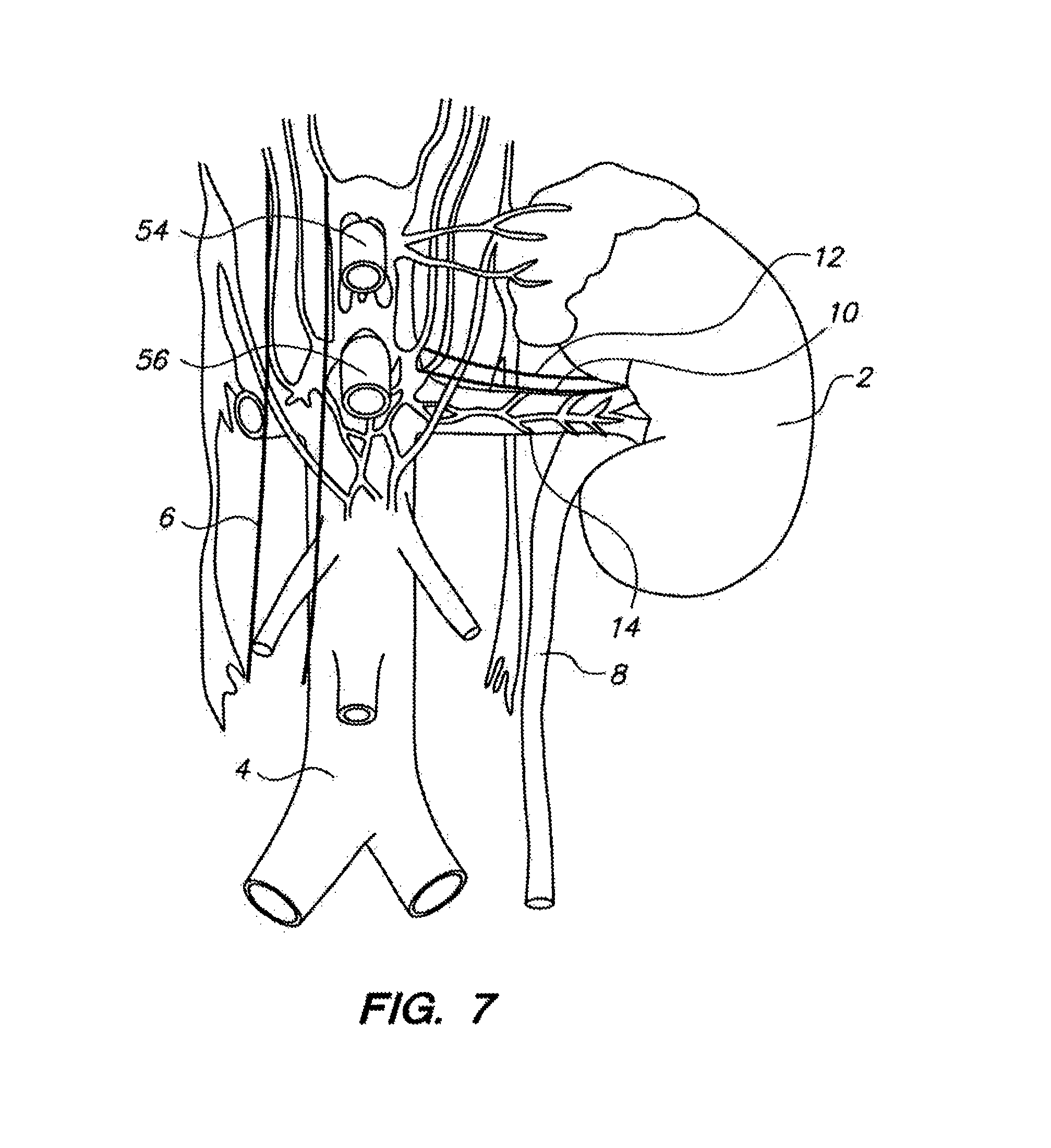
FIG. 7 depicts a close up partial view of renal, cardiovascular, and associated neuroanatomy in the abdomen adjacent the kidney.
FIG. 8 illustrates various aspects of a trans-ureteral renal plexus denervation intervention.
FIG. 9 illustrates various aspects of a trans-arterial renal plexus denervation intervention wherein instrumentation is taken across a portion of a wall of the celiac trunk artery.
FIG. 10 illustrates various aspects of a trans-arterial renal plexus denervation intervention wherein instrumentation is taken across a portion of a wall of the superior mesentary artery.
FIG. 11 illustrates various aspects of a trans-venous renal plexus denervation intervention wherein instrumentation is taken across a portion of a wall of the vena cava.
FIG. 12 illustrates various aspects of a trans-venous renal plexus denervation intervention wherein instrumentation is taken across a portion of a wall of the renal vein.
FIG. 13 illustrates various aspects of a process for creating a trans-lumenal access port from inside of a subject tissue lumen or structure, utilizing the access port for a diagnostic or interventional procedure, and closing the access port from inside of the subject tissue lumen.
FIGS. 14A-14H illustrate various aspects of a system for renal neuroplexus diagnostics and intervention in accordance with the present invention.
FIGS. 15A-15D illustrate various aspects of a system for renal neuroplexus diagnostics and intervention in accordance with the present invention, wherein OCT imaging techniques may be employed.
FIGS. 16-21 illustrate process embodiments in accordance with the present invention.
FIG. 22 illustrates an embodiment wherein a longitudinally displaced pattern may be used in a denervation treatment.
FIGS. 23A-23C illustrate an embodiment wherein a pullback technique may be utilized in a denervation treatment with a pre-shaped spiral instrument.
FIG. 24 illustrates an embodiment wherein an evacuated volume may be utilized to assist with a denervation treatment wherein an expandable device comprising one of more circuit elements is utilized in a denervation treatment.
FIGS. 25A and 25B illustrate embodiments wherein two or more guide instrument assemblies may be utilized to conduct a denervation treatment.
FIGS. 26A-26C illustrate an embodiment wherein a pullback technique may be utilized in a denervation treatment with a pre-shaped J-curve instrument.
FIGS. 27A-27C illustrate various aspects of manufacturing and behavior details of a pre-shaped spiral instrument embodiment.
FIGS. 28A and 28B illustrate various details of a pre-shaped J-curve instrument embodiment.
FIGS. 29-34 illustrate process embodiments in accordance with the present invention.
DETAILED DESCRIPTION
Referring to FIG. 1, the kidneys (2) are shown in relation to the aorta (4), vena cava (6), ureters (8), renal veins (12) and portions of the neural anatomy of the renal plexus (14), which is coupled to the renal arteries (10). Referring to FIG. 2, a close-up orthogonal view of a portion of a renal artery (10) is shown, with bands of contractile smooth muscle tissue (18) surrounding the longitudinal axis (16) circumferentially, and with strands of renal nerves (20) coupled to the renal artery (10), generally longitudinally along the renal artery (10). These strands of renal nerves (20) comprise the renal nerve plexus, or renal plexus, which may be embedded within the adventitia of the renal artery (10). This nerve plexus extends along the renal artery until it joins the parenchyma of the kidney (2). As briefly described above, hypertension and other diseases such as heart failure and chronic kidney disease are a few of the disease states that result from chronic activation of the sympathetic nervous system, especially the renal sympathetic nervous system, which comprises the renal plexus. Chronic activation of the sympathetic nervous system is a maladaptive response that drives the progression of these disease states. Indeed, the renal sympathetic nervous system has been identified as a major contributor to the complex pathophysiology of hypertension, various states of volume overload (such as congestive heart failure), and progressive heart disease, in experimental and clinical research studies. Given the knowledge that hypertension is commonly neurogenic, there are new clinical intervention paradigms evolving whereby an attempt is made to locate and ablate strands of renal nerves (20) comprising the renal plexus from the inside of the renal artery, via an endovascular approach. Various challenges are presented with such an approach, including locating and appropriately denervating the nerve strands without damaging or necrosing the tissue of the renal artery wall. In investigating extravascular approaches (i.e., approaching the renal plexus from outside of the walls of the renal artery), it has been determined that one of the key challenges is controllably navigating and operating an instrument to a retroperitoneal location whereby the renal plexus may be more directly denervated via radiofrequency ablation or other techniques. An electromechanically, or "robotically", operated elongate instrument control system provides important functionality for such a challenge.
Referring to FIG. 3, a robotic catheter system is depicted having an operator workstation (210) comprising a master input device (206), control button console (208), and a display (204) for the operator (202) to engage. In the depicted embodiment, a controller or control computer configured to operate the various aspects of the system is also located near the operator (202). The controller (212) comprises an electronic interface, or bus (248), configured to operatively couple the controller (212) with other components, such as an electromechanical instrument driver (164), RF generator (214), localization system (216), or fiber bragg shape sensing and/or localization system (218), generally via electronic leads (232, 230, 236, 234, 240, 238, 242, 244, 246, 226). Electromechanically or robotically controlled catheter systems similar to that depicted in FIG. 3 are available from Hansen Medical, Inc. under the tradename Sensei.RTM., and described, for example, in U.S. patent application Ser. Nos. 11/481,433, 11/073,363, 11/678,001 ("Intellisense") and Ser. No. 11/637,951, each of which is incorporated by reference in its entirety. In the depicted embodiment, the controller (212) preferably is operatively coupled (232) to the RF generator (214) and configured to control outputs of the RF generator (214), which may be dispatched via electronic lead (230) to the disposable instrument assembly (166). Similarly, the controller (212) preferably is operatively coupled (236) to a localization system, such as an electromagnetic or potential difference based localization system (216), such as those available under the tradenames CartoXP.RTM. and EnSite.RTM. from Biosense Webster, Inc., and St. Jude Medical, Inc., respectively. The localization system (216) preferably is operatively coupled via one or more leads (234) to the instrument assembly (166), and is configured to determine the three dimensional spatial position, and in certain embodiments orientation, of one or more sensors coupled to a distal portion of the instrument assembly relative to a coordinate system relevant to the controller and operator, such as a world coordinate system. Such position and/or orientation information may be communicated back to the controller (212) via the depicted electronic lead (236) or other signal communication configuration such as a wireless data communication system (not shown), to enable the controller (212) and operator (202) to understand where the distal portion of the instrument assembly (166) is in space--for control and safety purposes. Similarly, a fiber opticlocalization and/or shape sensing system (218) may be coupled between the controller (212) and instrument assembly (166) to assist with the determination of position and shape of portions of the instrument assembly, thermal sensing, contact sensing, and load sensing, as described, for example, in the aforementioned incorporated patent applications.
Various types of shape sensing fibers may be used in the fiber optic localization and/or shape sensing system (218). It is well known that by applying the Bragg equation (wavelength=2*d*sin(theta)) to detect wavelength changes in reflected light, elongation in a diffraction grating pattern positioned longitudinally along a fiber or other elongate structure maybe be determined. Further, with knowledge of thermal expansion properties of fibers or other structures which carry a diffraction grating pattern, temperature readings at the site of the diffraction grating may be calculated. "Fiberoptic Bragg grating" ("FBG") sensors or components thereof, available from suppliers such as Luna Innovations, Inc., of Blacksburg, Va., Micron Optics, Inc., of Atlanta, Ga., LxSix Photonics, Inc., of Quebec, Canada, and Ibsen Photonics AIS, of Denmark, have been used in various applications to measure strain in structures such as highway bridges and aircraft wings, and temperatures in structures such as supply cabinets.
The use of such technology in shapeable instruments is disclosed in commonly assigned U.S. patent application Ser. Nos. 11/690,116; 11/176,598; 12/012,795; 12/106,254; 12/507,727; 12/192,033; 12/236,478; and Ser. No. 12/837,440. The entirety of each of the above applications is incorporated by reference herein.
In an alternative variation, a single mode optical fiber is drawn with slight imperfections that result in index of refraction variations along the fiber core. These variations result in a small amount of backscatter that is called Rayleigh scatter. Changes in strain or temperature of the optical fiber cause changes to the effective length of the optical fiber. This change in the effective length results in variation or change of the spatial position of the Rayleigh scatter points. Cross correlation techniques can measure this change in the Rayleigh scattering and can extract information regarding the strain. These techniques can include using optical frequency domain reflectometer techniques in a manner that is very similar to that associated with low reflectivity fiber gratings. A more complete discussion of these methods can be found in M. Froggatt and J. Moore, "High-spatial-resolution distributed strain measurement in optical fiber with Rayleigh scatter", Applied Optics, Vol. 37, p. 1735, 1998 the entirety of which is incorporated by reference herein.
Methods and devices for calculating birefringence in an optical fiber based on Rayleigh scatter as well as apparatus and methods for measuring strain in an optical fiber using the spectral shift of Rayleigh scatter can be found in PCT Publication No. WO2006099056 filed on Mar. 9, 2006 and U.S. Pat. No. 6,545,760 filed on Mar. 24, 2000 both of which are incorporated by reference herein. Birefringence can be used to measure axial strain and/or temperature in a waveguide. Using Rayleigh scatter to determine birefringence rather than Bragg gratings offers several advantages. First, the cost of using Rayleigh scatter measurement is less than when using Bragg gratings. Rayleigh scatter measurement permits birefringence measurements at every location in the fiber, not just at predetermined locations. Since Bragg gratings require insertion at specific measurement points along a fiber, measurement of Rayleigh scatter allows for many more measurement points. Also, the process of physically "writing" a Bragg grating into an optical fiber can be time consuming as well as compromises the strength and integrity of the fiber. Such drawbacks do not occur when using Rayleigh scatter measurement.
In one embodiment, an optical fiber sensor (238), which may or may not include Bragg gratings, may be positioned between the distal tip of one or more instruments in the assembly and coupled proximally to the optical fiber sensor interrogator (218) in a manner described in U.S. Provisional Patent application No. 61/513,488 the entirety of which is incorporated by reference herein, and outputs from such system may be electronically communicated (240) to the controller (212) to facilitate control and safety features, such as closed loop shape control of one or more portions of the instrument assembly, as described, for example, in the aforementioned incorporated references. A feedback and control lead (226) is utilized to operatively couple the instrument driver (164) to the controller. This lead (226) carries control signals from the controller (212) to various components comprising the instrument driver (164), such as electric motors, and carries control signals from the various components of the instrument driver (164), such as encoder and other sensor signals, to the controller (212). The instrument driver (164) is coupled to the operating table (222) by a setup structure (220) which may be a simple structural member, as depicted, or a more complicated movable assembly, as described in the aforementioned incorporated references. A bus configuration (248) couples the various depicted leads (226, 246, 244, 242, 240, 236, 232) with the controller (212). Alternatively, wireless configurations may be utilized.
Referring to FIG. 4, an orthogonal view of an instrument driver (164) and instrument assembly (166) is depicted, this configuration having the ability to monitor loads applied to working members or tools placed through a working lumen defined by the instrument assembly (166). In this embodiment, such loads are determined with load sensors (168) located within the housing of the instrument driver, as described in the aforementioned incorporated references. In other embodiments, loads imparted to various tools or aspects of the instrument assembly (166) may be monitored using load sensors or components thereof which are embedded within or coupled to distal portions (170) of such tools or instrument assembly portions.
Referring to FIGS. 5A-5D, various closer views of aspects of instrument embodiments in accordance with the present invention are shown. Referring to FIG. 5A, a steerable sheath instrument (22) is depicted having a proximal interface (shown in the aforementioned incorporated by reference disclosures in reference to robotic sheath instrument embodiments) configured to be removably and driveably coupled to an instrument driver (164) such as that depicted in FIG. 4. The distal portion of the sheath instrument (22) comprises an expandable member such as a balloon, which may be controllably expanded via an inflation lumen (42), as shown in the detail view of FIG. 5B. Also shown in FIGS. 5A and 5B is an elongate steerable guide instrument (24) which may be proximally coaxially positioned through a guide insertion lumen (44) defined into the sheath instrument (22), and distally directed out through a side port formed through the balloon member (26), after being routed through an arcuate portion (46) of the guide insertion lumen (44). With the balloon member (26) in an inflated or deflated state, the depicted instrument assembly may be placed through a lumen and utilized to create a side port across the wall of the lumen. In one embodiment, a needle may initially be advanced through the sheath instrument lumen (44, 46) and across the subject tissue wall, followed by a dilator instrument and/or guidewire, which may be followed by the guide instrument (24) in an over-the-wire type technique using a working lumen defined into the guide instrument (24). As shown in FIGS. 5A and 5B, the distal portion of the elongate guide instrument (24) may be outfitted with one or more ultrasound transducers (28), one or more localization sensors (30), and one or more treatment elements (such as a radiofrequency electrode, a cryoablation reservoir, a high intensity focused ultrasound treatment transducer, a laser or other radiation emitter, or the like 32) which may be utilized to denervate nerve strands, such as those of the renal plexus. In another embodiment, the distal portion of the guide instrument (24) may be operatively coupled to an antenna, such as a microwave antenna, to sense reflected radiation, such as blackbody radiation, which may be correlated to the temperature of nearby tissues, as described, for example, in U.S. patent application Ser. No. 12/833,927, which is incorporated by reference herein in its entirety. Such an embodiment allows for direct sensing of thermal conditions in nearby tissue structures of interest--as opposed to other competing techniques such as thermocouples placed adjacent RF heating electrodes, which are more aptly configured to read the temperature of the electrodes rather than nearby tissues.
Referring to the close-up view of FIG. 5B, the side port of the balloon member (26) comprises a lumen port closure configuration having one or more closure clip elements (34) constrained in an open configuration by the geometry of the balloon member (26) to which it is coupled. Upon controllable inflation of a small clip deployment bladder (38) coupled to the balloon member (26) using an inflation lumen (40), the clip (34) may be advanced outward, and small barb-like fastening members (36) configured to fasten to nearby tissue structures upon exposure and mild advancement load from the deployment bladder (38) and/or balloon member (26) inflation will engage nearby tissue structures, while the clip (34) simultaneously will become unconstrained from its coupling with the structure of the balloon member (26) and will be free to resume an unloaded configuration, preferably configured to coapt the tissue around the circumference of the access port toward itself. Suitable clips made from bioinert metals such as nitinol are available from Medtronic Corporation and were invented by Coalescent Surgical, Inc. and cleared by the FDA for a different medical application (closure of vascular anastomosis). The fastening features (36) may be sintered onto the clips, welded, coupled with a preferably bioinert adhesive, or formed or etched into the same structure that comprises the fastening element (36). Referring ahead to FIG. 13, a process for utilizing a configuration such as that depicted in FIGS. 5A and 5B to create and subsequently close a lumen side port is illustrated.
Referring to FIG. 13, after positioning an expandable balloon member in a contracted form to a desired insertion location and orientation (i.e., roll orientation relative to the longitudinal axis commonly associated with a lumen) (148), the expandable balloon member maybe controllably inflated to substantially occlude the body lumen (with the exception of flow which may be facilitated through a working through-lumen of a subject sheath instrument) and create a relatively low-level hoop tension in portions of the body lumen adjacent to the expanded balloon member (150). An elongate diagnostic and/or interventional instrument may then be advanced out of a side port of the expandable balloon member (in one embodiment, as described above, in an over-the-needle, wire, or dilator configuration), creating a trans-lumenal access port (152). Using this access port, a diagnostic and/or interventional procedure may be conducted translumenally with one or more elongate instruments (154). When the interventional procedure has been completed, the elongate instruments may be refracted (156) and a controlled closure of the translumenal access port executed by urging the one or more closure clips away from a housing depression formed in the balloon member, and into at least a portion of the tissue structure adjacent the translumenal access port, with the one or more clips maintaining their constrained (i.e., constrained until they are uncoupled from the balloon member housing interface) configurations as they are fastened to the nearby tissue (158). A bladder and associated pressure control lumen, as shown in FIG. 5B, for example, may be utilized to controllably advance the one or more clips outward, as described above. With the one or more closure clips fastened to the subject tissue structure, preferably in a pattern about the annulus of the translumenal access port, incremental pressure in the bladder or other mechanism may be utilized to uncouple the one or more closure clips from the balloon member, allowing them to assume an unloaded configuration preferably selected to cause tissue coaptation about the previous location of the translumenal access port to urge the port closed (160). With the port closed, the instruments may be withdrawn (162).
Referring back to FIG. 5C, an embodiment similar to that of FIG. 5B is depicted, with the exception that an elongate treatment probe (58), such as a bendable or steerable needle, comprising a series plurality (59) of distally-located treatment elements (akin to element 32) coupled to a helically shaped (48) treatment probe distal portion that is configured to be inserted and/or wrapped around a given tissue structure for discrete, controlled ablation of such tissue structure. The helical shape (48) is selected to minimize the risk of stenosis by longitudinally stretching out a circumferential lesion (i.e., a non-stretched purely circumferential lesion may have scar tissue expansion inward from directly opposing tissue structure portions, leaving it more vulnerable to stenosis by such scarring; the helical pitch shape 48 is configured to avoid this). An orthogonal view is depicted in FIG. 5D.
Referring to FIGS. 6A, 6B, and 8, a trans-ureteral renal nerve plexus denervation procedure is illustrated. As shown in FIG. 6A, a guide and sheath instrument assembly similar to that depicted in FIGS. 5A and 5B may be inserted through the urethra (52) and into the bladder (50) where it may be navigated to cannulate one of the ureters (8) and be directed toward the kidney (2), as shown in FIG. 6B. Referring to FIG. 6B, with the sheath instrument (22) desirably located and oriented relative to the renal artery (10) (confirmation of which may be assisted using ultrasound, fluoroscopy, and other imaging modalities), a transcutaneous access port may be created through an expanded balloon member (26) to provide an elongate guide instrument, such as a robotically steerable guide instrument (24) with relatively immediate retroperitoneal access to the outside of the renal artery, and therefore the renal plexus. Such access may be utilized to directly ablate and/or otherwise denervate selected portions of the renal plexus. A similar configuration may be utilized to conduct a trans-lumenal diagnostic and/or interventional procedure via various other anatomical situations. For example, in an embodiment similar to that described in reference to FIGS. 5A-5D and 6A-6B, an elongate steerable instrument configuration may be utilized to move through the lower gastrointestinal tract, up into the intestine, and be utilized to cross the intestine closely adjacent the renal plexus to conduct a similar denervation procedure from a different anatomic platform. One or more stents or stentlike members may be left behind to bolster or replace the closure provided by the clip-like elements (34), and such stent or stentlike member may be subsequently removed, as directed by the physician, in a manner similar to that conducted in certain conventional ureter wound closure scenarios.
Referring to FIG. 8, a process flow for such a procedure is illustrated. With a sheath instrument advanced across a urethra and into the bladder (60), steerability and navigation capabilities of the sheath instrument may be utilized to cannulate a ureter (potentially using an over-the-wire technique) (62). The distal portion of the sheath instrument may be advanced into an optimal position and orientation for accessing the retroperitoneal space adjacent the renal artery and renal plexus (64). A balloon member may be expanded into a guide instrument deployment configuration wherein ureter portions adjacent the balloon are slightly tensioned in an expansive manner from the balloon inflation; the kidneys may continue to drain using a lumen defined through at least a portion of the balloon and/or sheath member (68). A guide member may be advanced out of a side port formed in the balloon member to create a translumenal access port (in some embodiments utilizing over the wire or over the needle techniques) (70). With the translumenal access created, the guide instrument may be advanced toward the desired neuroanatomy (72) from the outside of the renal artery, and controlled denervation accomplished using radiofrequency energy emission or other denervation modalities, as described above (74). Subsequently, the instrumentation may be retracted, the access port closed (for example, as described above), the balloon deflated, and normal function returned without the endolumenal instrumentation in place (76).
Referring to FIG. 7, various aspects of the cardiovascular and neurological anatomy around the renal system are depicted to illustrate that there are several translumenal access opportunities to the retroperitoneal region of the renal plexus, including but not limited to the vena cava (6), the renal veins (12), the celiac trunk artery (54), and the superior mesentery artery (56). Referring to FIG. 9, a process for implementing a translumenal renal plexus denervation with a trans-celiac approach is illustrated. A sheath instrument is advanced up the aorta and into the celiac trunk artery (78). An over the wire process may be utilized to gain full access to the celiac trunk for the distal portion of the sheath instrument (80). The distal portion of the sheath may be adjusted in position and orientation to optimize a translumenal approach toward the renal plexus (82). A balloon member coupled to the distal portion of the sheath member may be expanded to slightly tension the celiac trunk portions adjacent the balloon member, and blood may continue to flow past the balloon member using a lumen formed through the balloon member (86). A guide instrument may be advanced out of a side port of the sheath instrument to create a transvascular access port (88). In one embodiment, a sharpened needle may be utilized for the initial advancement, followed by the guide instrument in an over the needle interfacing relationship. The distal portion of the guide instrument may be positioned adjacent the renal plexus (90), and one or more RF electrodes may be utilized to controllably denervate portions of the renal plexus (92). Subsequently the guide instrument may be retracted, the transvascular access port closed (for example, using one or more clip members as described above in reference to FIG. 5B), the sheath balloon member deflated, and the sheath instrument retracted to leave a complete closure (94).
Referring to FIG. 10, a process for implementing a translumenal renal plexus denervation with a trans-mesentary approach is illustrated. A sheath instrument is advanced up the aorta and into the superior mesentary artery (96). An over the wire process may be utilized to gain full access to the celiac trunk for the distal portion of the sheath instrument (98). The distal portion of the sheath may be adjusted in position and orientation to optimize a translumenal approach toward the renal plexus (100). A balloon member coupled to the distal portion of the sheath member may be expanded to slightly tension the superior mesentery artery portions adjacent the balloon member, and blood may continue to flow past the balloon member using a lumen formed through the balloon member (104). A guide instrument may be advanced out of a side port of the sheath instrument to create a transvascular access port (106). In one embodiment, a sharpened needle may be utilized for the initial advancement, followed by the guide instrument in an over the needle interfacing relationship. The distal portion of the guide instrument may be positioned adjacent the renal plexus (108), and one or more RF electrodes may be utilized to controllably denervate portions of the renal plexus (110). Subsequently the guide instrument may be retracted, the transvascular access port closed (for example, using one or more clip members as described above in reference to FIG. 5B), the sheath balloon member deflated, and the sheath instrument retracted to leave a complete closure (112).
Referring to FIG. 11, a process for implementing a translumenal renal plexus denervation with a trans-vena-cava approach is illustrated. A sheath instrument is advanced up into the vena cava from a femoral or other access point (114). The distal portion of the sheath may be adjusted in position and orientation to optimize balloon member positioning for a translumenal approach toward the renal plexus (116). A balloon member coupled to the distal portion of the sheath member may be expanded to slightly tension the celiac trunk portions adjacent the balloon member, and blood may continue to flow past the balloon member using a lumen formed through the balloon member (120). A guide instrument may be advanced out of a side port of the sheath instrument to create a transvascular access port (122). In one embodiment, a sharpened needle may be utilized for the initial advancement, followed by the guide instrument in an over the needle interfacing relationship. The distal portion of the guide instrument may be positioned adjacent the renal plexus (124), and one or more RF electrodes may be utilized to controllably denervate portions of the renal plexus (126). Subsequently the guide instrument may be retracted, the transvascular access port closed (for example, using one or more clip members as described above in reference to FIG. 5B), the sheath balloon member deflated, and the sheath instrument retracted to leave a complete closure (128).
Referring to FIG. 12, a process for implementing a translumenal renal plexus denervation with a renal vein approach is illustrated. A sheath instrument is advanced up the vena cava and into the renal vein (130). An over the wire process may be utilized to gain full access to the renal vein for the distal portion of the sheath instrument (132). The distal portion of the sheath may be adjusted in position and orientation to optimize a translumenal approach toward the renal plexus (134). A balloon member coupled to the distal portion of the sheath member may be expanded to slightly tension the celiac trunk portions adjacent the balloon member, and blood may continue to flow past the balloon member using a lumen formed through the balloon member (138). A guide instrument may be advanced out of a side port of the sheath instrument to create a transvascular access port (140). In one embodiment, a sharpened needle may be utilized for the initial advancement, followed by the guide instrument in an over the needle interfacing relationship. The distal portion of the guide instrument may be positioned adjacent the renal plexus (142), and one or more RF electrodes may be utilized to controllably denervate portions of the renal plexus (144). Subsequently the guide instrument may be retracted, the transvascular access port closed (for example, using one or more clip members as described above in reference to FIG. 5B), the sheath balloon member deflated, and the sheath instrument retracted to leave a complete closure (146).
Referring to FIGS. 14A-14G, various aspects of configurations selected to controllably denervate portions of a renal plexus or fibers thereof are illustrated. As shown in FIG. 14A, a robotic sheath instrument (22) and guide instrument (24) assembly is depicted being advanced up the aorta (4) and into the renal artery (10). The coaxial slidable coupling of the two robotic instruments is useful in the depicted embodiment for telescoping the smaller instrument relative to the larger, as depicted in FIGS. 14B and 14C, for example. In another embodiment, a single robotic guide type instrument may be utilized without the load-shielding and related fine-control benefits of having a "home base" sheath structure (22) positioned at the aorta (4) as shown, for example, in FIGS. 14B and 14C. In another embodiment, a non-robotic sheath may be utilized along with a robotic guide instrument (24). In yet another embodiment, two non-robotic instruments may be utilized, such as steerable catheters or sheaths that are responsive to non-electromechanical pullwire or pushwire loading for steerability.
Referring again to FIG. 14A, several nerve tissue strands (20) are depicted surrounding portions of the renal artery (10), as are groups of juxtaglomerular apparatus (or "JGA") cells (198), which are known to be responsible, at least in part, for the production of renin in response to efferent neural signals through the fibers (20) of the renal plexus, and thereby correlated with increases in blood pressure. Also shown are several arterioles (196) where the renal artery (4) branches down to meet the kidney.
Referring to FIG. 14B, the larger sheath instrument (22) is positioned at the mouth of the renal artery (10) while the smaller guide instrument (24) preferably is electromechanically advanced, and navigated to avoid local tissue trauma. As described above in reference to FIGS. 5A-5D, the distal portion of the guide instrument (24) may be equipped with various sensors (i.e., such as ultrasound transducers, localization sensors, thermocouples, and/or radiation antennae such as microwave antennae for blackbody radiation sensing) and/or treatment elements (i.e., such as high intensity focused ultrasound transducers, RF electrodes, laser emission elements, fluid emission elements, and the like). Referring to FIG. 14C, further insertion of the guide instrument (24) into the renal artery is facilitated by the electromechanical control of a robotic catheter system, the navigation of which may be facilitated by imaging modalities such as transcutaneous ultrasound, transvascular ultrasound, intravascular ultrasound, fluoroscopy, and navigation within a registered three-dimensional virtual environment created using images from modalities such as computed tomography, 3-dimensional computed tomography, magnetic resonance, X-ray, fluoroscopy, and the like, as described, for example, in the aforementioned incorporated references. For example, in one embodiment, a "no touch" insertion may be accomplished utilizing the stability provided by the placement of the sheath instrument (22), along with the navigability of a registered and real-time (or near real-time) imaged robotically steerable guide instrument (24).
Referring to FIG. 14D, subsequent to cannulation of the renal artery (10) to a position approximately adjacent the renal arterioles (196), a brief mapping study or investigation may be executed. This mapping study may be preceded by preoperative or intraoperative imaging to determine at least some information regarding the positions, or likely positions, of aspects of the renal plexus. Referring again to FIG. 14D, in one embodiment, a flexible, expandable device (292), such as a controllably expandable balloon or stentlike structure, may be controllably deployed from the guide instrument (24) and expanded to provide a direct interface between the tissues of the subject lumen and circuit elements (294) of the expandable device (292), the circuit elements being configured to detect nearby electrical signals, and in one embodiment to be alternatively be utilized to treat the nearby tissues through the controllable flow of current therethrough. In one embodiment, a conformal electronics polymer material, such as that available under the tradename MC10.RTM. by MC10 Corporation of Cambridge, Mass., may be utilized to embed radiofrequency ("RF") or other electrode circuitry within an inflatable or expandable substrate, as depicted in FIGS. 14D and 14E. Referring to the close up view of FIG. 14F, the circuit elements (294) may have sharpened probing portions (296) configured to protrude into nearby tissues, such as the walls of the renal artery (4), to gain closer proximity to signals passing through nearby neural structures, such as the depicted renal plexus fibers (20), and/or to gain closer proximity to structures to be denervated or altered in a treatment phase, such as by applying RF energy for selective denervation by heating. Full inflation or expansion of the associated expandable device (292) may be required to seat the probing portions (296) across portions of the nearby tissue structures, and the assembly of the expandable device (292), circuit elements (294), and probing portions (296) preferably is configured to be retractable back into the delivery instrument (24) without damage to nearby structures. In the embodiment depicted in FIGS. 14D-14F, deflation or controlled outer geometry shrinking of the expandable device (292), concomitant with incremental insertion of the guide instrument (24) and slight refraction of the expandable device (292), may be utilized to safely retract the expandable device after mapping and/or treatment.
Referring to FIG. 14G, in another embodiment, an individual probe member (298), such as an RF needle tip, may be utilized to selectively probe pertinent tissue structures for both mapping and treatment steps. Preferably the controller of the robotic catheter system is configured to not only controllably navigate the probe member (298) to locations of interest with a desirable insertion vector and insertion location, but also to store trajectory, path, location, and other information pertinent to each diagnostic and/or treatment step for constant monitoring of the procedure, and also ease of repeatability--or ease of avoiding repeatability (i.e., in scenarios wherein it is not desirable to conduct two RF heating bouts on the same tiny volume of tissue).
Referring to FIG. 14H, in one embodiment, a probe member (298) may be navigated directly to discrete JGA cells (198) or lesions of JGA cells to selectively destroy these directly. Any of the embodiments described herein may incorporate load sensing capabilities of the subject robotic catheter system, along with haptic input device features, to facilitate fine, atraumatic, predictable navigation of the diagnostic and/or treatment tools.
Referring to FIG. 15A, in another embodiment, an optical coherence tomography (or "OCT") fiber (300) may be coupled between a distal lens (302) and a proximal emitter/interferometer (not shown; available from sources such as ThorLabs, Inc., of Newton, N.J.) to facilitate OCT tissue structure threshold sensing (i.e., the sensing and/or visualization of boundaries of nearby tissue structures, such as the renal artery (10) wall thresholds, nerve fiber 20 structure thresholds, and the like) with a virtual field of view (304) dependent upon the lens (302) and emissions parameters. Such OCT imaging analysis may be utilized not only to locate structures of interest, but also to treat such structures--with near-realtime analysis of not only the tissue structure thresholds, but also thresholds of other objects, such as RF electrode probe tips and the like. The embodiment of FIG. 15A features an OCT configuration wherein the lens (302) is located on a distal face of the guide instrument (24). Referring to FIG. 15B, an arcuate configuration of the OCT fiber (300) proximal to the side-oriented lens (302) and field of view (304) may be utilized for a side-capturing configuration. Referring to FIG. 15C, another side-capturing configuration is facilitated by a mirror or reflector (306) configured to reflect outgoing and incoming light signals as shown.
Referring to FIG. 15D, an embodiment is shown wherein a working volume (318) is evacuated of blood to facilitate greater flexibility with light-based imaging technologies, such as video and OCT. In other words, the embodiments of FIGS. 15A-15C showed the lens (302) purposefully in almost direct opposition to nearby tissue structures, to avoid scattering and other effects of red blood cells and other elements of flowing blood which may negatively impact such imaging. The embodiment of FIG. 15D addresses this concern by temporarily (i.e., for a short period of time, as dictated by the pathophysiology of the associated kidney and other tissue structures) evacuating the working volume (318) of blood. This is accomplished in the depicted embodiment by inflating two expandable occlusive elements (308, 310), such as balloons, and evacuating the captured blood using simple vacuum proximally through the sheath (22) and associated instruments. A larger delivery member (314) accommodates coupling of the guide instrument (24) and also the volume capture assembly, which comprises the two expandable occlusive elements (308, 310) and a coupling member (312). A guide instrument port (316) allows for slidable coupling of the proximal expandable occlusive element (310) and the guide instrument (24). With such a configuration, various imaging devices may be utilized to create images of nearby anatomy, such as ultrasound (in which case a transmissive medium, such as saline, may be pumped into the working volume for sound wave transmission enhancement and subsequently removed), CCD cameras, CMOS cameras, fiberscopes, and the like, in addition to the aforementioned imaging configurations such as OCT.
Referring to FIGS. 16-21, various process embodiments are illustrated wherein one or more minimally invasive instruments may be utilized in diagnostic and/or interventional medical procedures. Referring to FIG. 16, after a remotely steerable sheath catheter instrument is inserted into the aorta and navigated toward the renal artery (175), the renal artery may be cannulated, for example with a coaxially associated remotely steerable guide instrument that is movably coupled to the sheath instrument (174). An interactive imaging study, or steps thereof, may be conducted of the renal artery and associated neural anatomy using one or more minimally invasive imaging modalities, such as ultrasound, fluoroscopy, and/or OCT (176), as described above. The results of the imaging study may be utilized to create a mapping representation of the neural anatomy relative to the renal artery anatomy, for example, by stimulating one or more of the associated nerve fibers and observing resulting signal conduction (178). In other words, referring back to FIGS. 14E and 14F, in one embodiment, one or more of the proximal (i.e., closer to the aorta in the variation of FIG. 14E) circuit elements and/or associated probing portions (element 296 of FIG. 14F) may be used to stimulate or electrify adjacent nerve fiber (20) portions at such proximal position, and the conduction of such stimulation may be detected with each of the other circuit elements (294) to monitor or "map" the associated conduction pathways. The results of such mapping may be utilized in the selective denervation of portions of the renal plexus, for example, by transmitting current to heat and denervate such portions (180). The mapping configuration may then be utilized to confirm that the denervation was, indeed, successful, or to what extent, with further stimulation of the pertinent fibers and monitoring of the results. Further, renin levels, such as in the renal vein, may be monitored to determine a level of treatment success associated with the thermal denervation treatment. Similarly, alcohol and other fluids may be utilized and monitored for denervation. Ultimately, the pertinent instruments may be retracted and the vascular access closed (182).
Referring to FIG. 17, a process similar to that of FIG. 16 is depicted, with the exception that a venous route is utilized to conduct denervation near the renal artery. This is believed to be less clinically complicated in certain scenarios. The catheter instrumentation is inserted into the inferior vena cava and navigated toward the renal vein (184). The renal vein is cannulated with a guide instrument movably coupled to the sheath instrument (186). The imaging study is conducted not only on the neural anatomy, but also on the renal vein anatomy and renal artery anatomy to understand the relationships of these three and other nearby tissue structures (188). The results of the imaging study may be utilized as inputs in a mapping subprocess, wherein one or more nerve fibers may be stimulated and the resulting signal conduction observed (190). The neural anatomy map resulting from the mapping efforts may be utilized for selective denervation treatment of the renal plexus (192), as well as in generating feedback to an operator regarding the effectiveness of various denervation attempts (as described above, renin levels also may be monitored). Subsequently the instruments may be retracted and the vascular access closed (194).
The embodiment of FIG. 18 illustrates that process configurations such as those described above in reference to FIGS. 16 and 17 may be broadly applied to many tissue structures that define one or more lumens through which the pertinent instrumentation may be advanced and utilized. Referring to FIG. 18, a catheter instrument may be inserted into the tissue structure defining a lumen believed to be associated with targeted neural tissue (252). The lumen may be cannulated with the catheter instrument (254). An interactive imaging study may be conducted to create an image-based anatomic mapping representation of the neural anatomy and other pertinent tissue structures (256), and an expandable device such as that described in reference to FIGS. 14E and 14F may be utilized to observe signal conduction (258) and create an electrical mapping which may be utilized to monitor the effectiveness of the treatment steps (260). Subsequently the instrumentation may be removed and access to the pertinent lumens and/or tissue structures discontinued (262).
FIG. 19 illustrates aspects of an embodiment wherein a robotically-steerable catheter instrument specifically is utilized (as described above, the aforementioned catheter instruments may or may not be remotely electromechanically navigable). With the robotic catheter instrumentation inserted into the pertinent lumen, such as an aorta in this example (264), precision navigation and control features of the robotic instrument may be utilized during the insertional navigation (266), anatomic imaging may be conducted (268), electrical mapping may be conducted (270), and selective denervation may be conducted (272), followed by removal of the pertinent instrumentation and closure of the vascular access (274). FIG. 21 illustrates a related embodiment with the additional step depicted (290) of observing feedback indicators, such as renin levels in blood exiting the renal vein and/or neural conduction paradigms with the mapping configuration, as confirming techniques for monitoring and/or adjusting treatment in a closed loop type of configuration.
Referring to FIG. 20, a robotic catheter system such as that described and incorporated above may be utilized to operate an off-the-shelf treatment head such those available on instruments from the Ardian division of Medtronic Corporation, to improve the navigability of such treatment head, and combine the treatment capabilities of such treatment head with additional diagnostic and treatment capabilities, such those described herein. As shown in FIG. 20, after a renal plexus denervation treatment head has been coupled to a distal portion of a robotic catheter instrument (276), the instrument may be inserted into an aorta or other lumen and navigated toward the renal artery or other targeted tissue structure (278). In the depicted renal intervention embodiment, the renal artery may be cannulated using the navigation control of the robotic instrumentation (280), after which an anatomic imaging study may be conducted (282), an electrical mapping study conducted (284), selective denervation attempted with feedback from the mapping configuration (286), and subsequent removal of the instruments and closure of the access (288).
Referring to FIG. 22, in another embodiment, a configuration similar to that depicted in FIG. 14G is depicted, and in the embodiment of FIG. 14G, is being operated to create a pattern of treatments (200) that is substantially elliptical, and that is configured to reduce the chances of post-intervention stenosis or other complications, due to the fact that the treatment contacts forming the pattern are spread over a larger length, longitudinally, of the targeted tissue structure (here a renal artery 10). Other patterns may be created within the defined lumen space, such as sets of curves, portions of circumferential lines, and the like.
Referring to FIGS. 23A-23C, a configuration is illustrated wherein a substantially helical treatment element (320) configured to conform to the targeted lumen (here a renal artery 10 lumen) may be pushed out the distal end of the delivery system (here a robotic sheath instrument 24), and then pulled back (322) proximally as the instrument (24) is withdrawn proximally, creating an opportunity to cause RF electrodes or other treatment elements coupled to the helical member (320) to create a longitudinal lesion configured to denervate targeted nerve fibers (20) which may be disposed about the targeted lumen. The treatment elements coupled to the helical member (320) may be configured or operated to remain in an "on" mode (i.e., treatment inducing; such as current flow mode with RF electrode treatment elements) during pullback (322), or may be configured to switch on and off intermittently with various patterns over time, such patterns being pre-programmable. FIGS. 23B and 23C illustrate further pullback (322) of the treatment assembly (24, 320), which may be automated using an "autoretract" functionality of the robotic guide/sheath catheter systems, descriptions of which are incorporated by reference herein.
Referring to FIG. 24, a set of expandable members (308, 310, such as a set of two balloons) may be used to isolate the nearby treatment environment for a diagnostic/treatment configuration (292, 294) such as that depicted in FIGS. 14D-14F. As shown in FIG. 24, a distal expandable balloon member (308), coupled to a proximal expandable balloon member (310) by a coupling member (312) that preferably defines an inflation lumen for the distal expandable balloon member (310), may be inserted in a collapsed form (not shown) through a lumen defined through the guide instrument (24), expanded (as illustrated), and utilized to vacuum away blood captured in the capture volume (318) for diagnostic and/or treatment steps. With the capture volume isolated, carbon dioxide or other bioinert gases, or saline, may be infused through an infusion lumen fluidly coupled to the capture volume (318) through one or more of the elongate proximal instruments (24, 22, 312) to facilitate diagnostic and/or treatment steps, such as improved tissue apposition, improved electrical conduction, and/or improved imaging and/or visualization, such as direct visualization using an associated fiber imaging bundle or imaging chip configured to have a field of view within or adjacent to the capture volume, or an ultrasound or OCT imaging configuration as described above.
Referring to FIGS. 25A and 25B, in another embodiment, two or more elongate steerable instruments (24, 25) may be utilized simultaneously from the same sheath instrument (23) configured to host and stabilize both guide instruments (24, 25) and advance a plurality of diagnostic and/or interventional probe members (298, 299). Such a sheath/guide configuration is described in the aforementioned incorporated by reference disclosures, and may be utilized herein to expedite and improve upon diagnostic and treatment steps as described above. For example, such a configuration may be utilized to create diametrically opposed lesions, to facilitate faster pattern creation, as described in reference to FIG. 22, and to assist with load-counterload relationships in delicate tissue intervention. FIG. 25B illustrates an embodiment emphasizing that the sheath instrument (23, or 24 in other depictions herein) may be advanced distally into the renal artery or other subject tissue structure lumen, to provide easy access for one or more guide instruments (24, 25) to the arterioles (196) or other distal structures, which may be advantageous for direct diagnostics and intervention pertinent to the JGA cells, for example.
In another embodiment, a stent or stentlike member configured to elute one or more drugs or compounds configured to denervate the nearby targeted neural plexus tissue may be deployed into a structure of interest, such as a renal artery or renal vein, to accomplish such denervation over a designated period of time, after which the stent or stentlike member may be removed, resorbed, or left in place as a substantially bioinert prosthesis.
Referring to FIGS. 26A-26C, another embodiment is illustrated wherein a steerable sheath (22) and guide instrument (24) assembly may be utilized to provide direct access for a pre-shaped or pre-bent interventional instrument, such as a pre-bent J-curve instrument (352) featuring a bent electrode portion (354) configured to create a lesion in the same shape when current is flowed through the electrode portion (354) and into nearby tissue structures, such as the interior of the renal artery (10), as shown, or portions of the renal vein, nearby renal nerve strands (20), JGA cells (198), and the like. In one embodiment, in a manner similar to that described above in reference to FIGS. 23A-23C, wherein a pre-bent spiral or helical instrument (320) is pulled back through the associated vessel, the arcuate or curved interventional instrument of FIGS. 26A-26C may also be controllably pulled back to create an elongate lesion to disrupt the pre-existing electrical communication pathways of the nearby neural plexus tissue. FIGS. 26B and 26C show additional levels of progression of pullback (350). In another embodiment, the instrument (352) may be controllably rotated during pullback, or during a portion of pullback, to establish a predetermined pattern of contact between the electrode portion (354) and the surrounding tissue structures (10, 20, 198, 196). During pullback, current may be either continuously flowed through the electrode portion (354), in which case a "long linear lesion" may be produced in a solid (i.e., noninterrupted) linear, curvy, or other pattern, or the current may be discontinuously flowed through the electrode portion (354), creating a "long linear lesion" may be produced in a discontinuous (i.e., interrupted) linear, curvy, or other pattern.
Referring to FIGS. 27A-27C, further details regarding aspects of a helical or spiral type pre-bent or pre-formed instrument treatment element (320) may be formed and configured to behave are illustrated. Referring to FIG. 27A, a series of spiral windings (360) created on a mandrel (358) may be utilized to form a helical or spiral pre-bent or pre-formed shape into a wire (356). Heat treatment may be utilized to maintain this form for the wire (356) after removal of the mandrel, as shown in FIG. 27B, wherein the spiral wire (356) is shown coupled to a piece of metal hypotube (364) via a metallic crimpling coupler (362), which provides the wire (356) with a proximal handle or deliver member for operative manipulation. Referring to FIG. 27C, depending upon what materials are utilized for the wire (356), it may be placed in a restraining tube or lumen (366) that radially constrains the outer diameter of the spiral--an in such radially-collapsed configuration, the instrument may be configured to still retain the generally spiral or helical configuration until it is released from such constraint, after which it may be configured to return to the radially expanded configuration, as in FIG. 27B.
Referring to FIG. 28A, in one embodiment, a J-curve type arcuate instrument (352) may be formed by taking a J-curve--shaped insulated guidewire, such as those available from Terumo Corporation, and removing a portion of the polymeric outer insulation, for example, with a knife or other sharp instrument, to leave behind an exposed metallic core portion which may be utilized as a conductive electrode portion (370), and distal (372) and proximal (368) portions which remain insulated and generally nonconductive relative to the conductive electrode portion (370). A farther out perspective view is shown in FIG. 28B.
Referring to FIGS. 29-34, various process embodiments are illustrated wherein one or more minimally invasive instruments may be utilized in diagnostic and/or interventional medical procedures utilizing pre-shaped instruments as described above. Referring to FIG. 16, after a remotely steerable sheath catheter instrument is inserted into the aorta and navigated toward the renal artery (175), the renal artery may be cannulated, for example with a coaxially associated remotely steerable guide instrument that is movably coupled to the sheath instrument (174). An interactive imaging study, or steps thereof, may be conducted of the renal artery and associated neural anatomy using one or more minimally invasive imaging modalities, such as ultrasound, fluoroscopy, and/or OCT (176), as described above. The results of the imaging study may be utilized to create a mapping representation of the neural anatomy relative to the renal artery anatomy, for example, by stimulating one or more of the associated nerve fibers and observing resulting signal conduction (178). In other words, referring back to FIGS. 14E and 14F, in one embodiment, one or more of the proximal (i.e., closer to the aorta in the variation of FIG. 14E) circuit elements and/or associated probing portions (element 296 of FIG. 14F) may be used to stimulate or electrify adjacent nerve fiber (20) portions at such proximal position, and the conduction of such stimulation may be detected with each of the other circuit elements (294) to monitor or "map" the associated conduction pathways. The results of such mapping may be utilized in the selective denervation of portions of the renal plexus using a pre-shaped instrument such as a J-curved or spiral shaped instrument, for example, by transmitting current to heat and denervate such portions (324). The mapping configuration may then be utilized to confirm that the denervation was, indeed, successful, or to what extent, with further stimulation of the pertinent fibers and monitoring of the results. Further, renin levels, such as in the renal vein, may be monitored to determine a level of treatment success associated with the thermal denervation treatment. Similarly, alcohol and other fluids may be utilized and monitored for denervation. Ultimately, the pertinent instruments may be retracted and the vascular access closed (326).
Referring to FIG. 30, a process similar to that of FIG. 29 is depicted, with the exception that a venous route is utilized to conduct denervation near the renal artery. This is believed to be less clinically complicated in certain scenarios. The catheter instrumentation is inserted into the inferior vena cava and navigated toward the renal vein (184). The renal vein is cannulated with a guide instrument movably coupled to the sheath instrument (186). The imaging study is conducted not only on the neural anatomy, but also on the renal vein anatomy and renal artery anatomy to understand the relationships of these three and other nearby tissue structures (188). The results of the imaging study may be utilized as inputs in a mapping subprocess, wherein one or more nerve fibers may be stimulated and the resulting signal conduction observed (190). The neural anatomy map resulting from the mapping efforts may be utilized for selective denervation treatment of the renal plexus using a pre-shaped instrument, such as a j-shaped or spiral-shaped guidewire containing one or more electrodes (328), as well as in generating feedback to an operator regarding the effectiveness of various denervation attempts (as described above, renin levels also may be monitored). Subsequently the instruments may be retracted and the vascular access closed (330).
The embodiment of FIG. 31 illustrates that process configurations such as those described above in reference to FIGS. 29 and 30 may be broadly applied to many tissue structures that define one or more lumens through which the pertinent instrumentation may be advanced and utilized. Referring to FIG. 31, a catheter instrument may be inserted into the tissue structure defining a lumen believed to be associated with targeted neural tissue (252). The lumen may be cannulated with the catheter instrument (254). An interactive imaging study may be conducted to create an image-based anatomic mapping representation of the neural anatomy and other pertinent tissue structures (256), and an expandable device such as that described in reference to FIGS. 14E and 14F may be utilized to observe signal conduction (258) and create an electrical mapping which may be utilized to monitor the effectiveness of the treatment steps with the pre-shaped instrumentation (332). Subsequently the instrumentation may be removed and access to the pertinent lumens and/or tissue structures discontinued (334).
FIG. 32 illustrates aspects of an embodiment wherein a robotically-steerable catheter instrument specifically is utilized (as described above, the aforementioned catheter instruments may or may not be remotely electromechanically navigable). With the robotic catheter instrumentation inserted into the pertinent lumen, such as an aorta in this example (264), precision navigation and control features of the robotic instrument may be utilized during the insertional navigation (266), anatomic imaging may be conducted (268), electrical mapping may be conducted (270), and selective denervation may be conducted using pre-shaped instruments (336), followed by removal of the pertinent instrumentation and closure of the vascular access (338). FIG. 34 illustrates a related embodiment with the additional step depicted (346) of observing feedback indicators, such as renin levels in blood exiting the renal vein and/or neural conduction paradigms with the mapping configuration, as confirming techniques for monitoring and/or adjusting treatment in a closed loop type of configuration. Steps 344 and 348 of the embodiment of FIG. 34 are similar to steps 336 and 338 of the embodiment of FIG. 32.
Referring to FIG. 33, a robotic catheter system such as that described and incorporated above may be utilized to operate an off-the-shelf treatment head such as those available on instruments from the Ardian division of Medtronic Corporation, to improve the navigability of such treatment head, and combine the treatment capabilities of such treatment head with additional diagnostic and treatment capabilities, such those described herein. As shown in FIG. 20, after a renal plexus denervation treatment head has been coupled to a distal portion of a robotic catheter instrument (276), the instrument may be inserted into an aorta or other lumen and navigated toward the renal artery or other targeted tissue structure (278). In the depicted renal intervention embodiment, the renal artery may be cannulated using the navigation control of the robotic instrumentation (280), after which an anatomic imaging study may be conducted (282), an electrical mapping study conducted (284), selective denervation attempted with feedback from the pre-shaped instrument mapping configuration (340), and subsequent removal of the instruments and closure of the access (342).
Any of the aforementioned deployed structures may comprise resorbable materials in addition to the aforementioned nonresorbable materials--to facilitate combinations and permutations which may be completely resorbed, leaving behind a biologically healed access wound.
Further, any of the aforementioned configurations may be applied to other tissue structure configurations involving natural lumens to be navigated, and nearby neural or other tissue structures to be targeted. For example, the techniques and configurations herein may be applied to other aspects of the cardiovascular and renal/urinary systems, as well as other anatomic subsystems including but not limited to the respiratory, upper gastric, and lower gastric subsystems.
Various exemplary embodiments of the invention are described herein. Reference is made to these examples in a non-limiting sense. They are provided to illustrate more broadly applicable aspects of the invention. Various changes may be made to the invention described and equivalents may be substituted without departing from the true spirit and scope of the invention. In addition, many modifications may be made to adapt a particular situation, material, composition of matter, process, process act(s) or step(s) to the objective(s), spirit or scope of the present invention. Further, as will be appreciated by those with skill in the art that each of the individual variations described and illustrated herein has discrete components and features which may be readily separated from or combined with the features of any of the other several embodiments without departing from the scope or spirit of the present inventions. All such modifications are intended to be within the scope of claims associated with this disclosure.
Any of the devices described for carrying out the subject interventions may be provided in packaged combination for use in executing such interventions. These supply "kits" further may include instructions for use and be packaged in sterile trays or containers as commonly employed for such purposes.
The invention includes methods that may be performed using the subject devices. The methods may comprise the act of providing such a suitable device. Such provision may be performed by the end user. In other words, the "providing" act merely requires the end user obtain, access, approach, position, set-up, activate, power-up or otherwise act to provide the requisite device in the subject method. Methods recited herein may be carried out in any order of the recited events which is logically possible, as well as in the recited order of events.
Exemplary aspects of the invention, together with details regarding material selection and manufacture have been set forth above. As for other details of the present invention, these may be appreciated in connection with the above-referenced patents and publications as well as generally known or appreciated by those with skill in the art. For example, one with skill in the art will appreciate that one or more lubricious coatings (e.g., hydrophilic polymers such as polyvinylpyrrolidone-based compositions, fluoropolymers such as tetrafluoroethylene, hydrophilic gel or silicones) may be used in connection with various portions of the devices, such as relatively large interfacial surfaces of movably coupled parts, if desired, for example, to facilitate low friction manipulation or advancement of such objects relative to other portions of the instrumentation or nearby tissue structures. The same may hold true with respect to method-based aspects of the invention in terms of additional acts as commonly or logically employed.
In addition, though the invention has been described in reference to several examples optionally incorporating various features, the invention is not to be limited to that which is described or indicated as contemplated with respect to each variation of the invention. Various changes may be made to the invention described and equivalents (whether recited herein or not included for the sake of some brevity) may be substituted without departing from the true spirit and scope of the invention. In addition, where a range of values is provided, it is understood that every intervening value, between the upper and lower limit of that range and any other stated or intervening value in that stated range, is encompassed within the invention.
Also, it is contemplated that any optional feature of the inventive variations described may be set forth and claimed independently, or in combination with any one or more of the features described herein. Reference to a singular item, includes the possibility that there are plural of the same items present. More specifically, as used herein and in claims associated hereto, the singular forms "a," "an," "said," and "the" include plural referents unless the specifically stated otherwise. In other words, use of the articles allow for "at least one" of the subject item in the description above as well as claims associated with this disclosure. It is further noted that such claims may be drafted to exclude any optional element. As such, this statement is intended to serve as antecedent basis for use of such exclusive terminology as "solely," "only" and the like in connection with the recitation of claim elements, or use of a "negative" limitation.
Without the use of such exclusive terminology, the term "comprising" in claims associated with this disclosure shall allow for the inclusion of any additional element--irrespective of whether a given number of elements are enumerated in such claims, or the addition of a feature could be regarded as transforming the nature of an element set forth in such claims. Except as specifically defined herein, all technical and scientific terms used herein are to be given as broad a commonly understood meaning as possible while maintaining claim validity.
The breadth of the present invention is not to be limited to the examples provided and/or the subject specification, but rather only by the scope of claim language associated with this disclosure.
* * * * *
References
D00000
D00001
D00002
D00003
D00004
D00005
D00006
D00007
D00008
D00009
D00010
D00011
D00012

D00013

D00014
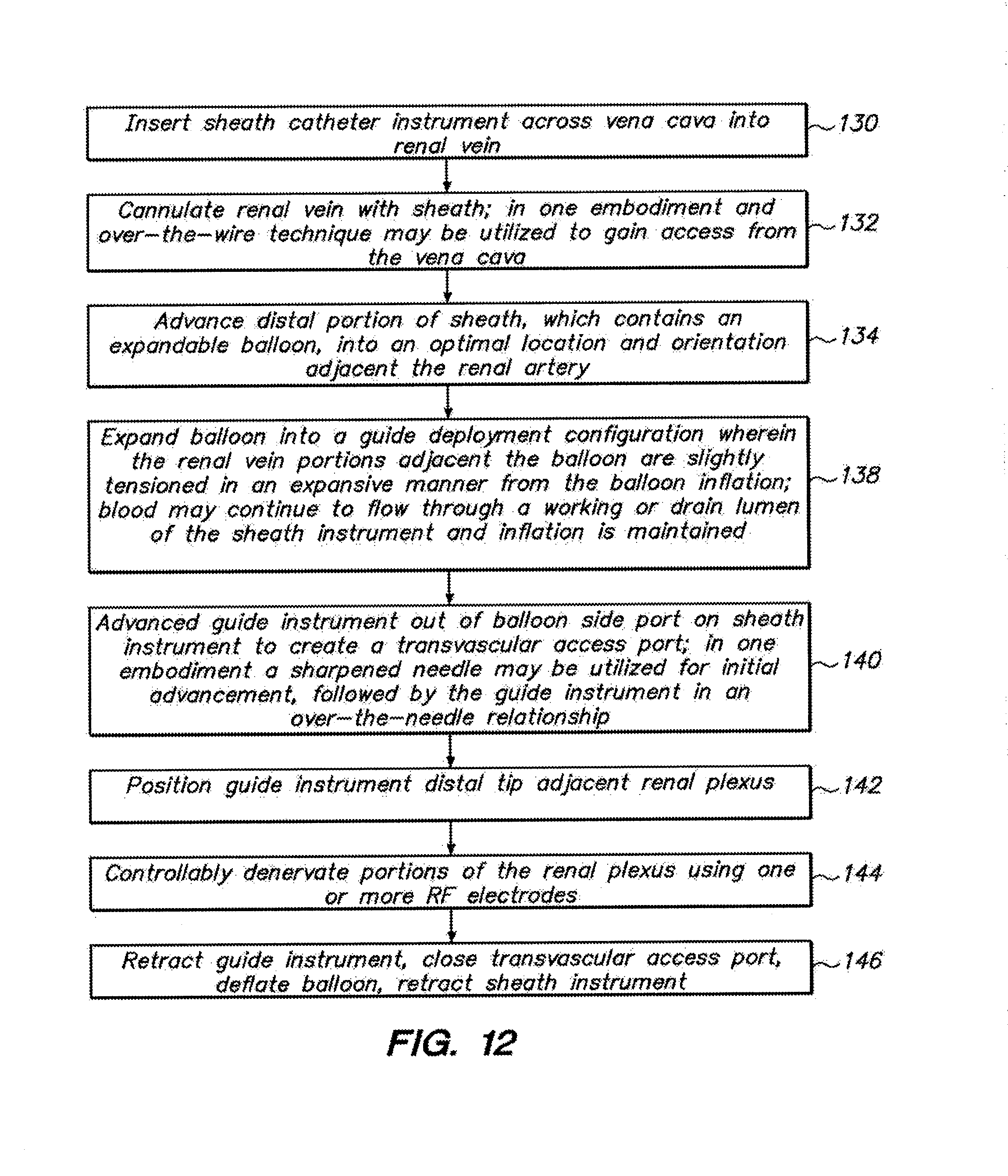
D00015

D00016

D00017

D00018

D00019

D00020

D00021

D00022

D00023

D00024

D00025

D00026

D00027

D00028

D00029

D00030

D00031

D00032

D00033

D00034

D00035

D00036

D00037

D00038

D00039

D00040

D00041

D00042

D00043

D00044

D00045

D00046
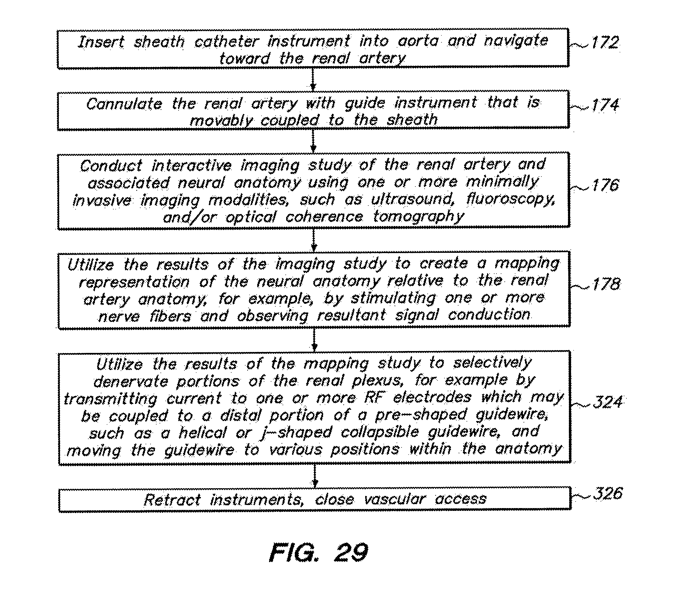
D00047

D00048

D00049

D00050

D00051

XML
uspto.report is an independent third-party trademark research tool that is not affiliated, endorsed, or sponsored by the United States Patent and Trademark Office (USPTO) or any other governmental organization. The information provided by uspto.report is based on publicly available data at the time of writing and is intended for informational purposes only.
While we strive to provide accurate and up-to-date information, we do not guarantee the accuracy, completeness, reliability, or suitability of the information displayed on this site. The use of this site is at your own risk. Any reliance you place on such information is therefore strictly at your own risk.
All official trademark data, including owner information, should be verified by visiting the official USPTO website at www.uspto.gov. This site is not intended to replace professional legal advice and should not be used as a substitute for consulting with a legal professional who is knowledgeable about trademark law.