Nubbed plate
Pavento , et al.
U.S. patent number 10,327,915 [Application Number 15/846,344] was granted by the patent office on 2019-06-25 for nubbed plate. This patent grant is currently assigned to DePuy Synthes Products, Inc.. The grantee listed for this patent is DePuy Synthes Products, Inc.. Invention is credited to Sheryl Furlan, John Riley Hawkins, Nicholas Pavento, Douglas Raymond.


| United States Patent | 10,327,915 |
| Pavento , et al. | June 25, 2019 |
Nubbed plate
Abstract
A separate nub component between the plate and an intervertebral fusion cage, wherein the nub is attached to the plate. The nub lessens the undesired pivotal movement of the plate. It is believed that when the nub fits snugly between the endplates of the adjacent vertebral bodies, it acts as a stop against the undesired pivotal movement of the plate.
| Inventors: | Pavento; Nicholas (North Attleboro, MA), Hawkins; John Riley (Cumberland, RI), Furlan; Sheryl (Middleboro, MA), Raymond; Douglas (Bridgewater, MA) | ||||||||||
|---|---|---|---|---|---|---|---|---|---|---|---|
| Applicant: |
|
||||||||||
| Assignee: | DePuy Synthes Products, Inc.
(Raynham, MA) |
||||||||||
| Family ID: | 49114785 | ||||||||||
| Appl. No.: | 15/846,344 | ||||||||||
| Filed: | December 19, 2017 |
Prior Publication Data
| Document Identifier | Publication Date | |
|---|---|---|
| US 20180125672 A1 | May 10, 2018 | |
Related U.S. Patent Documents
| Application Number | Filing Date | Patent Number | Issue Date | ||
|---|---|---|---|---|---|
| 15581571 | Apr 28, 2017 | 9872781 | |||
| 14845481 | Jun 6, 2017 | 9668877 | |||
| 13413264 | Mar 1, 2016 | 9271836 | |||
| Current U.S. Class: | 1/1 |
| Current CPC Class: | A61F 2/30744 (20130101); A61F 2/442 (20130101); A61F 2/447 (20130101); A61F 2/4455 (20130101); A61B 17/7059 (20130101); A61F 2310/00407 (20130101); A61F 2002/30774 (20130101); A61F 2002/305 (20130101); A61F 2002/30784 (20130101); A61F 2002/30604 (20130101); A61F 2310/00359 (20130101); A61F 2002/2817 (20130101); A61F 2002/30785 (20130101); A61F 2002/30836 (20130101); A61F 2220/0008 (20130101); A61F 2310/00017 (20130101); A61F 2310/00203 (20130101); A61F 2002/30578 (20130101); A61F 2310/00161 (20130101); A61F 2002/30843 (20130101); A61F 2310/00023 (20130101); A61F 2002/30482 (20130101); A61F 2310/00053 (20130101); A61F 2310/00239 (20130101); A61F 2002/30616 (20130101); A61F 2310/00011 (20130101); A61F 2002/30594 (20130101); A61F 2002/30622 (20130101); A61F 2/30965 (20130101); A61F 2002/30378 (20130101); A61F 2310/00029 (20130101); A61F 2/4465 (20130101); A61F 2002/30428 (20130101); A61F 2002/448 (20130101); A61F 2310/00047 (20130101); A61F 2002/30607 (20130101); A61F 2002/30787 (20130101); A61F 2310/00179 (20130101); A61F 2310/00101 (20130101); A61F 2002/30593 (20130101); A61F 2002/2835 (20130101) |
| Current International Class: | A61F 2/44 (20060101); A61F 2/30 (20060101); A61B 17/70 (20060101); A61F 2/28 (20060101) |
| Field of Search: | ;623/17.11-17.16 |
References Cited [Referenced By]
U.S. Patent Documents
| 1636636 | July 1927 | Humble |
| 1677337 | July 1928 | Grove |
| 2304703 | December 1942 | O'Leary |
| 4105034 | August 1978 | Shalaby et al. |
| 4130639 | December 1978 | Shalaby et al. |
| 4140678 | February 1979 | Shalaby et al. |
| 4141087 | February 1979 | Shalaby et al. |
| 4205399 | June 1980 | Jamiolkowski et al. |
| 4208511 | June 1980 | Jamiolkowski et al. |
| 4743256 | May 1988 | Brantigan |
| 4904261 | February 1990 | Dove et al. |
| 4955908 | September 1990 | Frey et al. |
| 5041113 | August 1991 | Biedermann et al. |
| 5123926 | June 1992 | Pisharodi |
| 5147361 | September 1992 | Ojima et al. |
| 5209751 | May 1993 | Farris et al. |
| 5306308 | April 1994 | Gross et al. |
| 5352231 | October 1994 | Brumfield et al. |
| 5391170 | February 1995 | McGuire et al. |
| 5395372 | March 1995 | Holt et al. |
| 5397364 | March 1995 | Kozak et al. |
| 5443514 | August 1995 | Steffee |
| 5443515 | August 1995 | Cohen et al. |
| 5464407 | November 1995 | McGuire |
| 5464929 | November 1995 | Bezwada et al. |
| 5499986 | March 1996 | Dimarco |
| 5529580 | June 1996 | Kusunoki et al. |
| 5534031 | July 1996 | Matsuzaki et al. |
| 5578034 | November 1996 | Estes |
| 5591166 | January 1997 | Bernhardt |
| 5595751 | January 1997 | Bezwada et al. |
| 5597579 | January 1997 | Bezwada et al. |
| 5601553 | February 1997 | Trebing et al. |
| 5607687 | March 1997 | Bezwada et al. |
| 5609636 | March 1997 | Kohrs et al. |
| 5618552 | April 1997 | Bezwada et al. |
| 5620458 | April 1997 | Green et al. |
| 5620698 | April 1997 | Bezwada et al. |
| 5645598 | July 1997 | Brosnahan, III |
| 5645850 | July 1997 | Bezwada et al. |
| 5648088 | July 1997 | Bezwada et al. |
| 5662655 | September 1997 | Laboureau et al. |
| 5676666 | October 1997 | Oxland et al. |
| 5698213 | December 1997 | Jamiolkowski et al. |
| 5700583 | December 1997 | Jamiolkowski et al. |
| 5713899 | February 1998 | Marnay et al. |
| 5716415 | February 1998 | Steffee |
| 5755796 | May 1998 | Ibo |
| 5776196 | July 1998 | Matsuzaki et al. |
| 5779707 | July 1998 | Bertholet et al. |
| 5785713 | July 1998 | Jobe |
| 5788698 | August 1998 | Savornin |
| 5797912 | August 1998 | Runciman et al. |
| 5797918 | August 1998 | McGuire et al. |
| 5800435 | September 1998 | Errico |
| 5800440 | September 1998 | Stead |
| 5859150 | January 1999 | Jamiolkowski et al. |
| 5888223 | March 1999 | Bray, Jr. |
| 5904689 | May 1999 | Jonjic |
| 5913860 | June 1999 | Scholl |
| 6039761 | March 2000 | Li et al. |
| 6049026 | April 2000 | Muschler |
| 6056749 | May 2000 | Kuslich |
| 6066175 | May 2000 | Henderson |
| 6086593 | July 2000 | Bonutti |
| 6093205 | July 2000 | McLeod et al. |
| 6099531 | August 2000 | Bonutti |
| 6106557 | August 2000 | Robioneck et al. |
| 6117174 | September 2000 | Nolan |
| 6120503 | September 2000 | Michelson |
| 6126689 | October 2000 | Brett |
| 6139550 | October 2000 | Michelson |
| 6156037 | December 2000 | LeHuec |
| 6159211 | December 2000 | Boriani et al. |
| 6159244 | December 2000 | Suddaby |
| 6174311 | January 2001 | Branch et al. |
| 6179875 | January 2001 | Von Strempel |
| 6190414 | February 2001 | Young et al. |
| 6193757 | February 2001 | Foley et al. |
| 6200306 | March 2001 | Klostermeyer et al. |
| 6206922 | March 2001 | Zdeblick et al. |
| 6224602 | May 2001 | Hayes |
| 6231610 | May 2001 | Geisler |
| 6235059 | May 2001 | Benezech et al. |
| 6306170 | October 2001 | Ray |
| 6330845 | December 2001 | Meulink |
| 6336928 | January 2002 | Guerin et al. |
| 6342055 | January 2002 | Eisermann et al. |
| 6342074 | January 2002 | Simpson |
| 6364880 | April 2002 | Michelson |
| 6368351 | April 2002 | Glenn et al. |
| 6375462 | April 2002 | Holweg et al. |
| 6387130 | May 2002 | Stone et al. |
| 6395031 | May 2002 | Foley et al. |
| 6406478 | June 2002 | Kuo |
| 6409766 | June 2002 | Brett |
| 6413278 | July 2002 | Marchosky |
| 6423063 | July 2002 | Bonutti |
| 6428575 | August 2002 | Koo et al. |
| 6432106 | August 2002 | Fraser |
| 6447544 | September 2002 | Michelson |
| 6447546 | September 2002 | Bramlet et al. |
| 6454769 | September 2002 | Wagner et al. |
| 6461359 | October 2002 | Tribus et al. |
| 6471724 | October 2002 | Zdeblick et al. |
| 6488710 | December 2002 | Besselink |
| 6508818 | January 2003 | Steiner |
| 6558387 | May 2003 | Errico et al. |
| 6558423 | May 2003 | Michelson |
| 6562073 | May 2003 | Foley |
| 6565570 | May 2003 | Sterett et al. |
| 6572619 | June 2003 | Santilli |
| 6579290 | June 2003 | Hardcastle et al. |
| 6602257 | August 2003 | Thramann |
| 6629998 | October 2003 | Lin |
| 6682563 | January 2004 | Scharf |
| 6695846 | February 2004 | Richelsoph et al. |
| 6730125 | May 2004 | Lin |
| 6730127 | May 2004 | Michelson |
| 6733531 | May 2004 | Trieu |
| 6736850 | May 2004 | Davis |
| 6743257 | June 2004 | Castro |
| 6745255 | June 2004 | Yen et al. |
| 6761738 | July 2004 | Boyd |
| 6770096 | August 2004 | Bolger et al. |
| 6773437 | August 2004 | Ogilvie et al. |
| 6776781 | August 2004 | Uwaydah |
| 6805714 | October 2004 | Sutcliffe |
| 6808537 | October 2004 | Michelson |
| 6824564 | November 2004 | Crozet |
| 6824565 | November 2004 | Muhanna et al. |
| 6833006 | December 2004 | Foley et al. |
| 6835208 | December 2004 | Marchosky |
| 6837905 | January 2005 | Lieberman |
| 6849093 | February 2005 | Michelson |
| 6890335 | May 2005 | Grabowski et al. |
| 6890355 | May 2005 | Michelson |
| 6945973 | September 2005 | Bray |
| 6972019 | December 2005 | Michelson |
| 6974479 | December 2005 | Trieu |
| 6974480 | December 2005 | Messerli et al. |
| 6984234 | January 2006 | Bray |
| 7001385 | February 2006 | Bonutti |
| 7033394 | April 2006 | Michelson |
| 7041135 | May 2006 | Michelson |
| 7044971 | May 2006 | Suddaby |
| 7056341 | June 2006 | Crozet |
| 7063491 | June 2006 | French |
| 7070598 | July 2006 | Lim et al. |
| 7077864 | July 2006 | Byrd et al. |
| 7087055 | August 2006 | Lim et al. |
| 7112222 | September 2006 | Fraser et al. |
| 7112223 | September 2006 | Davis |
| 7135024 | November 2006 | Cook et al. |
| 7135043 | November 2006 | Nakahara et al. |
| 7163561 | January 2007 | Michelson |
| 7172627 | February 2007 | Fiere et al. |
| 7226482 | June 2007 | Messerli et al. |
| 7232463 | June 2007 | Falahee |
| 7232464 | June 2007 | Mathieu et al. |
| 7238203 | July 2007 | Bagga et al. |
| 7238206 | July 2007 | Lange et al. |
| 7255698 | August 2007 | Michelson |
| 7276081 | October 2007 | Coates et al. |
| 7288094 | October 2007 | Lindemann et al. |
| 7288095 | October 2007 | Baynham et al. |
| 7288114 | October 2007 | Lange |
| 7306605 | December 2007 | Ross |
| 7309358 | December 2007 | Berry et al. |
| 7311734 | December 2007 | Van et al. |
| 7316714 | January 2008 | Gordon et al. |
| 7318839 | January 2008 | Malberg et al. |
| 7323011 | January 2008 | Shepard et al. |
| 7326248 | February 2008 | Michelson |
| 7332209 | February 2008 | Yokouchi et al. |
| 7338525 | March 2008 | Ferree |
| 7341587 | March 2008 | Molz et al. |
| 7341590 | March 2008 | Ferree |
| 7354452 | April 2008 | Foley |
| 7361193 | April 2008 | Frey et al. |
| 7435262 | October 2008 | Michelson |
| 7438715 | October 2008 | Doubler et al. |
| 7452370 | November 2008 | Anderson |
| 7491237 | February 2009 | Randall et al. |
| 7527641 | May 2009 | Suh |
| 7594931 | September 2009 | Louis et al. |
| 7594932 | September 2009 | Aferzon et al. |
| 7601171 | October 2009 | Ainsworth |
| 7601173 | October 2009 | Messerli et al. |
| 7608062 | October 2009 | Sweeney |
| 7618456 | November 2009 | Mathieu et al. |
| 7628816 | December 2009 | Magerl et al. |
| 7641665 | January 2010 | Zubok et al. |
| 7655042 | February 2010 | Foley et al. |
| 7658766 | February 2010 | Melkent et al. |
| 7662182 | February 2010 | Zubok et al. |
| 7674279 | March 2010 | Johnson |
| 7704255 | April 2010 | Michelson |
| 7726002 | June 2010 | Shimp et al. |
| 7794502 | September 2010 | Michelson |
| 7815643 | October 2010 | Johnson et al. |
| 7815681 | October 2010 | Ferguson |
| 7846206 | December 2010 | Oglaza et al. |
| 7846210 | December 2010 | Perez-Cruet et al. |
| 7862616 | January 2011 | Lechmann et al. |
| 7871441 | January 2011 | Eckman |
| 7875062 | January 2011 | Lindemann et al. |
| 7875076 | January 2011 | Mathieu et al. |
| 7883531 | February 2011 | De Coninck |
| 7887591 | February 2011 | Aebi et al. |
| 7887595 | February 2011 | Pimenta |
| 7909877 | March 2011 | Krueger et al. |
| 7993403 | August 2011 | Foley et al. |
| 8002808 | August 2011 | Morrison et al. |
| 8007523 | August 2011 | Wagner et al. |
| 8187329 | May 2012 | Theofilos |
| 8206423 | June 2012 | Siegal |
| 8216312 | July 2012 | Gray |
| 8236029 | August 2012 | Siegal |
| 8241328 | August 2012 | Siegal |
| 8246622 | August 2012 | Siegal et al. |
| 8323342 | December 2012 | Schwab |
| 8328812 | December 2012 | Siegal et al. |
| 8336559 | December 2012 | Kallabat et al. |
| 8337559 | December 2012 | Hansell et al. |
| 8343219 | January 2013 | Allain et al. |
| 8349015 | January 2013 | Bae et al. |
| 8357200 | January 2013 | Adl |
| 8454694 | June 2013 | Armstrong |
| 8460385 | June 2013 | Wensel |
| 8460387 | June 2013 | Theofilos |
| 8465524 | June 2013 | Siegal |
| 8470044 | June 2013 | Bertholet |
| 8480747 | July 2013 | Melkent |
| 8486109 | July 2013 | Siegal |
| 8491658 | July 2013 | Etminan |
| 8496691 | July 2013 | Blain |
| 8496708 | July 2013 | Blain |
| 8500783 | August 2013 | Baynham |
| 8551175 | October 2013 | Wensel |
| 8562651 | October 2013 | Metcalf |
| 8597330 | December 2013 | Siegal |
| 8613772 | December 2013 | Bray |
| 8617245 | December 2013 | Brett |
| 8628578 | January 2014 | Miller |
| 8641765 | February 2014 | Muhanna |
| 8672977 | March 2014 | Siegal et al. |
| 8690928 | April 2014 | Walkenhorst |
| 8690948 | April 2014 | Armstrong |
| 8747443 | June 2014 | Aferzon |
| 8758439 | June 2014 | Linares |
| 8777993 | July 2014 | Siegal et al. |
| 8821555 | September 2014 | Bae et al. |
| 8845638 | September 2014 | Siegal et al. |
| 8900235 | December 2014 | Siegal |
| 8906098 | December 2014 | Siegal |
| 8932359 | January 2015 | Brett |
| 8956416 | February 2015 | McCarthy |
| 9005293 | April 2015 | Moskowitz et al. |
| 9005295 | April 2015 | Kueenzi et al. |
| 9017408 | April 2015 | Siegal et al. |
| 9017413 | April 2015 | Siegal et al. |
| 9044334 | June 2015 | Siegal et al. |
| 9138330 | September 2015 | Hansell et al. |
| 9192419 | November 2015 | McDonough et al. |
| 9248028 | February 2016 | Gamache |
| 9254138 | February 2016 | Siegal et al. |
| 9265546 | February 2016 | Blain |
| 9265621 | February 2016 | Voellmicke |
| 9271836 | March 2016 | Pavento |
| 9278009 | March 2016 | Bray et al. |
| 9283092 | March 2016 | Siegal et al. |
| 9289311 | March 2016 | Whipple |
| 9364272 | June 2016 | Binder et al. |
| 9402735 | August 2016 | McDonough et al. |
| 9402738 | August 2016 | Niemiec et al. |
| 9408712 | August 2016 | Siegal et al. |
| 9492286 | November 2016 | Biedermann et al. |
| 9662225 | May 2017 | Pavento |
| 9668877 | June 2017 | Pavento |
| 9848992 | December 2017 | McDonough et al. |
| 2001/0031968 | October 2001 | Dorchak et al. |
| 2002/0029044 | March 2002 | Monassevitch et al. |
| 2002/0029082 | March 2002 | Muhanna |
| 2002/0095155 | July 2002 | Michelson |
| 2002/0099376 | July 2002 | Michelson |
| 2002/0138146 | September 2002 | Jackson |
| 2002/0143328 | October 2002 | Shluzas et al. |
| 2002/0151976 | October 2002 | Foley et al. |
| 2002/0156475 | October 2002 | Lerch |
| 2003/0004576 | January 2003 | Thalgott |
| 2003/0023305 | January 2003 | McKay |
| 2003/0028197 | February 2003 | Hanson et al. |
| 2003/0045940 | March 2003 | Eberlein et al. |
| 2003/0050645 | March 2003 | Parker et al. |
| 2003/0083748 | May 2003 | Lee et al. |
| 2003/0100949 | May 2003 | Michelson |
| 2003/0125739 | July 2003 | Bagga et al. |
| 2003/0130739 | July 2003 | Gerbec et al. |
| 2003/0153975 | August 2003 | Byrd et al. |
| 2003/0158555 | August 2003 | Sanders et al. |
| 2003/0187440 | October 2003 | Richelsoph et al. |
| 2003/0187506 | October 2003 | Ross et al. |
| 2003/0195632 | October 2003 | Foley et al. |
| 2003/0225409 | December 2003 | Freid |
| 2004/0024464 | February 2004 | Errico et al. |
| 2004/0034430 | February 2004 | Falahee |
| 2004/0092929 | May 2004 | Zindrick |
| 2004/0106996 | June 2004 | Liu et al. |
| 2004/0111089 | June 2004 | Stevens et al. |
| 2004/0127902 | July 2004 | Suzuki et al. |
| 2004/0127990 | July 2004 | Bartish et al. |
| 2004/0138662 | July 2004 | Landry et al. |
| 2004/0153065 | August 2004 | Lim |
| 2004/0153072 | August 2004 | Bonutti |
| 2004/0167625 | August 2004 | Beyar et al. |
| 2004/0193269 | September 2004 | Fraser et al. |
| 2004/0199253 | October 2004 | Link et al. |
| 2004/0199254 | October 2004 | Louis et al. |
| 2004/0210219 | October 2004 | Bray |
| 2004/0249377 | December 2004 | Kaes et al. |
| 2004/0254644 | December 2004 | Taylor |
| 2004/0260286 | December 2004 | Ferree |
| 2005/0021144 | January 2005 | Malberg et al. |
| 2005/0033433 | February 2005 | Michelson |
| 2005/0038513 | February 2005 | Michelson |
| 2005/0043800 | February 2005 | Paul et al. |
| 2005/0065608 | March 2005 | Michelson |
| 2005/0071006 | March 2005 | Kirschman |
| 2005/0071008 | March 2005 | Kirschman |
| 2005/0085913 | April 2005 | Fraser et al. |
| 2005/0096657 | May 2005 | Autericque |
| 2005/0101960 | May 2005 | Fiere |
| 2005/0113920 | May 2005 | Foley et al. |
| 2005/0143749 | June 2005 | Zalenski et al. |
| 2005/0143827 | June 2005 | Globerman et al. |
| 2005/0149192 | July 2005 | Zucherman et al. |
| 2005/0149193 | July 2005 | Zucherman et al. |
| 2005/0154391 | July 2005 | Doherty et al. |
| 2005/0159813 | July 2005 | Molz, IV |
| 2005/0177240 | August 2005 | Blain |
| 2005/0177245 | August 2005 | Leatherbury |
| 2005/0182416 | August 2005 | Lim et al. |
| 2005/0209696 | September 2005 | Lin et al. |
| 2005/0251260 | November 2005 | Gerber et al. |
| 2005/0261768 | November 2005 | Trieu |
| 2005/0277938 | December 2005 | Parsons |
| 2005/0278036 | December 2005 | Leonard et al. |
| 2006/0025860 | February 2006 | Li |
| 2006/0030851 | February 2006 | Bray et al. |
| 2006/0058801 | March 2006 | Schlienger et al. |
| 2006/0079961 | April 2006 | Michelson |
| 2006/0085071 | April 2006 | Lechmann et al. |
| 2006/0129424 | June 2006 | Chan |
| 2006/0142765 | June 2006 | Dixon et al. |
| 2006/0142858 | June 2006 | Colleran et al. |
| 2006/0142863 | June 2006 | Fraser |
| 2006/0178745 | August 2006 | Bartish et al. |
| 2006/0211952 | September 2006 | Kennedy |
| 2006/0229609 | October 2006 | Wang |
| 2006/0229729 | October 2006 | Gordon et al. |
| 2006/0235403 | October 2006 | Blain |
| 2006/0235409 | October 2006 | Blain |
| 2006/0235411 | October 2006 | Blain et al. |
| 2006/0235518 | October 2006 | Blain |
| 2006/0235535 | October 2006 | Ferree et al. |
| 2006/0241597 | October 2006 | Mitchell et al. |
| 2006/0241761 | October 2006 | Gately |
| 2006/0247650 | November 2006 | Yerby et al. |
| 2006/0259147 | November 2006 | Krishna et al. |
| 2006/0265068 | November 2006 | Schwab |
| 2006/0293753 | December 2006 | Thramann |
| 2007/0049941 | March 2007 | Thramann |
| 2007/0055252 | March 2007 | Blain et al. |
| 2007/0067035 | March 2007 | Falahee |
| 2007/0073398 | March 2007 | Fabian et al. |
| 2007/0106384 | May 2007 | Bray et al. |
| 2007/0106388 | May 2007 | Michelson |
| 2007/0129804 | June 2007 | Bentley et al. |
| 2007/0162138 | July 2007 | Heinz |
| 2007/0198016 | August 2007 | Zang |
| 2007/0213737 | September 2007 | Schermerhorn et al. |
| 2007/0213820 | September 2007 | Magerl et al. |
| 2007/0219635 | September 2007 | Mathieu et al. |
| 2007/0233118 | October 2007 | McLain |
| 2007/0233253 | October 2007 | Bray et al. |
| 2007/0233261 | October 2007 | Lopez et al. |
| 2007/0233263 | October 2007 | Melkent et al. |
| 2007/0250167 | October 2007 | Bray et al. |
| 2007/0255416 | November 2007 | Melkent et al. |
| 2007/0265631 | November 2007 | Fox |
| 2007/0270957 | November 2007 | Heinz |
| 2007/0270965 | November 2007 | Ferguson |
| 2007/0276490 | November 2007 | Mateyka |
| 2007/0282449 | December 2007 | De et al. |
| 2007/0293948 | December 2007 | Bagga et al. |
| 2007/0299521 | December 2007 | Glenn et al. |
| 2008/0015694 | January 2008 | Tribus |
| 2008/0027550 | January 2008 | Link et al. |
| 2008/0033440 | February 2008 | Moskowitz et al. |
| 2008/0051890 | February 2008 | Waugh |
| 2008/0051897 | February 2008 | Lopez et al. |
| 2008/0065219 | March 2008 | Dye |
| 2008/0077247 | March 2008 | Murillo et al. |
| 2008/0082173 | April 2008 | Delurio et al. |
| 2008/0097436 | April 2008 | Culbert et al. |
| 2008/0103597 | May 2008 | Lechmann et al. |
| 2008/0103598 | May 2008 | Trudeau et al. |
| 2008/0109005 | May 2008 | Trudeau et al. |
| 2008/0125865 | May 2008 | Abdelgany |
| 2008/0132949 | June 2008 | Aferzon et al. |
| 2008/0132958 | June 2008 | Pech et al. |
| 2008/0133012 | June 2008 | McGuckin |
| 2008/0133014 | June 2008 | Gately et al. |
| 2008/0161925 | July 2008 | Brittan |
| 2008/0167666 | July 2008 | Fiere et al. |
| 2008/0177307 | July 2008 | Moskowitz et al. |
| 2008/0183293 | July 2008 | Parry et al. |
| 2008/0183294 | July 2008 | Adl |
| 2008/0221690 | September 2008 | Chaput et al. |
| 2008/0221694 | September 2008 | Warnick et al. |
| 2008/0234822 | September 2008 | Govil et al. |
| 2008/0243136 | October 2008 | Prager et al. |
| 2008/0249569 | October 2008 | Waugh et al. |
| 2008/0249575 | October 2008 | Waugh et al. |
| 2008/0249625 | October 2008 | Waugh et al. |
| 2008/0255620 | October 2008 | Strauss et al. |
| 2008/0269806 | October 2008 | Zhang et al. |
| 2008/0281425 | November 2008 | Thalgott et al. |
| 2008/0294262 | November 2008 | Levieux |
| 2008/0300601 | December 2008 | Fabian et al. |
| 2008/0300634 | December 2008 | Gray |
| 2008/0306596 | December 2008 | Jones et al. |
| 2008/0306598 | December 2008 | Hansen et al. |
| 2008/0312698 | December 2008 | Bergeron et al. |
| 2008/0312742 | December 2008 | Abernathie |
| 2009/0012529 | January 2009 | Blain |
| 2009/0030421 | January 2009 | Hawkins et al. |
| 2009/0030519 | January 2009 | Falahee |
| 2009/0030520 | January 2009 | Biedermann et al. |
| 2009/0062921 | March 2009 | Michelson |
| 2009/0088849 | April 2009 | Armstrong et al. |
| 2009/0099554 | April 2009 | Forster et al. |
| 2009/0099610 | April 2009 | Johnson et al. |
| 2009/0099661 | April 2009 | Bhattacharya et al. |
| 2009/0105771 | April 2009 | Lei et al. |
| 2009/0105774 | April 2009 | Jones et al. |
| 2009/0105830 | April 2009 | Jones et al. |
| 2009/0105831 | April 2009 | Jones et al. |
| 2009/0125028 | May 2009 | Teisen et al. |
| 2009/0131988 | May 2009 | Bush et al. |
| 2009/0132054 | May 2009 | Zeegers |
| 2009/0143859 | June 2009 | McClellan et al. |
| 2009/0164020 | June 2009 | Janowski et al. |
| 2009/0182428 | July 2009 | McClellan, III |
| 2009/0182430 | July 2009 | Tyber |
| 2009/0192549 | July 2009 | Sanders et al. |
| 2009/0192613 | July 2009 | Wing et al. |
| 2009/0192614 | July 2009 | Beger et al. |
| 2009/0192615 | July 2009 | Tyber et al. |
| 2009/0192616 | July 2009 | Zielinski |
| 2009/0198245 | August 2009 | Phan |
| 2009/0198287 | August 2009 | Chiu |
| 2009/0198339 | August 2009 | Kleiner et al. |
| 2009/0210062 | August 2009 | Thalgott et al. |
| 2009/0210064 | August 2009 | Lechmann et al. |
| 2009/0224023 | September 2009 | Moskowitz et al. |
| 2009/0234364 | September 2009 | Crook |
| 2009/0248092 | October 2009 | Bellas et al. |
| 2009/0259316 | October 2009 | Ginn et al. |
| 2009/0265007 | October 2009 | Colleran |
| 2009/0270873 | October 2009 | Fabian |
| 2009/0287251 | November 2009 | Bae et al. |
| 2009/0306779 | December 2009 | Ahn |
| 2009/0326543 | December 2009 | Fabian, Jr. |
| 2009/0326580 | December 2009 | Anderson |
| 2009/0326589 | December 2009 | Lemoine |
| 2010/0004747 | January 2010 | Lin |
| 2010/0016901 | January 2010 | Robinson |
| 2010/0016973 | January 2010 | De et al. |
| 2010/0023128 | January 2010 | Malberg |
| 2010/0030334 | February 2010 | Molz, IV |
| 2010/0036496 | February 2010 | Yu et al. |
| 2010/0042159 | February 2010 | Butler |
| 2010/0057206 | March 2010 | Duffield et al. |
| 2010/0069969 | March 2010 | Ampuero et al. |
| 2010/0070037 | March 2010 | Parry |
| 2010/0087925 | April 2010 | Kostuik et al. |
| 2010/0106249 | April 2010 | Tyber et al. |
| 2010/0137987 | June 2010 | Diao et al. |
| 2010/0145457 | June 2010 | Felt et al. |
| 2010/0145459 | June 2010 | McDonough et al. |
| 2010/0145460 | June 2010 | McDonough et al. |
| 2010/0179656 | July 2010 | Theofilos |
| 2010/0185287 | July 2010 | Allard et al. |
| 2010/0185289 | July 2010 | Kirwan et al. |
| 2010/0185292 | July 2010 | Hochschuler et al. |
| 2010/0204739 | August 2010 | Bae et al. |
| 2010/0217325 | August 2010 | Hochschuler et al. |
| 2010/0217393 | August 2010 | Theofilos |
| 2010/0249935 | September 2010 | Slivka et al. |
| 2010/0249937 | September 2010 | Blain |
| 2010/0286777 | November 2010 | Errico et al. |
| 2010/0286781 | November 2010 | Bullard |
| 2010/0286783 | November 2010 | Lechmann et al. |
| 2010/0292696 | November 2010 | Chantelot et al. |
| 2010/0292737 | November 2010 | Suh |
| 2010/0305704 | December 2010 | Messerli et al. |
| 2010/0312345 | December 2010 | Duffield |
| 2011/0009908 | January 2011 | Ferguson |
| 2011/0009966 | January 2011 | Michelson |
| 2011/0015675 | January 2011 | Howard et al. |
| 2011/0015745 | January 2011 | Bucci |
| 2011/0082550 | April 2011 | Yeh |
| 2011/0082555 | April 2011 | Martz et al. |
| 2011/0098747 | April 2011 | Donner et al. |
| 2011/0106159 | May 2011 | Nazeck |
| 2011/0144703 | June 2011 | Krause et al. |
| 2011/0166656 | July 2011 | Thalgott et al. |
| 2011/0184415 | July 2011 | Anderson et al. |
| 2011/0190892 | August 2011 | Kirschman |
| 2011/0202136 | August 2011 | Brittan |
| 2011/0208311 | August 2011 | Janowski |
| 2011/0213421 | September 2011 | Binder et al. |
| 2011/0230971 | September 2011 | Donner et al. |
| 2011/0251689 | October 2011 | Seifert et al. |
| 2011/0282453 | November 2011 | Greenhalgh et al. |
| 2011/0319998 | December 2011 | O'Neil et al. |
| 2012/0041559 | February 2012 | Melkent |
| 2012/0078371 | March 2012 | Gamache et al. |
| 2012/0078372 | March 2012 | Gamache et al. |
| 2012/0078373 | March 2012 | Gamache et al. |
| 2012/0083889 | April 2012 | Purcell et al. |
| 2012/0143336 | June 2012 | Aflatoon et al. |
| 2012/0150301 | June 2012 | Gamache et al. |
| 2012/0150303 | June 2012 | Linares |
| 2012/0158143 | June 2012 | Shapiro |
| 2012/0191190 | July 2012 | Trieu |
| 2012/0197401 | August 2012 | Duncan et al. |
| 2012/0203230 | August 2012 | Adams |
| 2012/0209331 | August 2012 | Michelson |
| 2012/0226319 | September 2012 | Armstrong |
| 2012/0253406 | October 2012 | Bae et al. |
| 2013/0041471 | February 2013 | Siegal et al. |
| 2013/0060337 | March 2013 | Petersheim |
| 2013/0073044 | March 2013 | Gamache |
| 2013/0079883 | March 2013 | Butler et al. |
| 2013/0166027 | June 2013 | Bellas |
| 2013/0238095 | September 2013 | Pavento |
| 2013/0268080 | October 2013 | Melkent |
| 2013/0310939 | November 2013 | Fabian |
| 2013/0325071 | December 2013 | Niemiec |
| 2013/0345813 | December 2013 | Frank |
| 2014/0039623 | February 2014 | Iott |
| 2014/0067069 | March 2014 | Lopez |
| 2014/0107786 | April 2014 | Geisler |
| 2014/0114415 | April 2014 | Tyber |
| 2014/0135930 | May 2014 | Georges |
| 2014/0142705 | May 2014 | Duffield |
| 2014/0156009 | June 2014 | Armstrong |
| 2014/0172103 | June 2014 | O'Neil |
| 2014/0364917 | December 2014 | Sandstrom et al. |
| 2015/0297356 | October 2015 | Gamache et al. |
| 2015/0313721 | November 2015 | Gamache et al. |
| 2015/0374511 | December 2015 | Pavento |
| 2016/0045325 | February 2016 | Bellas et al. |
| 2016/0128846 | May 2016 | Voellmicke |
| 2016/0213487 | July 2016 | Wilson et al. |
| 2016/0317317 | November 2016 | Marchek et al. |
| 2016/0324660 | November 2016 | Pavento |
| 2016/0324662 | November 2016 | McDonough et al. |
| 2017/0304068 | October 2017 | Bellas et al. |
| 2017/0312090 | November 2017 | Sharabani et al. |
| 201244104 | May 2009 | CN | |||
| 19710392 | Jul 1999 | DE | |||
| 1609444 | Dec 2005 | EP | |||
| 1683490 | Jul 2006 | EP | |||
| 1774926 | Apr 2007 | EP | |||
| 1459711 | Jul 2007 | EP | |||
| 1847240 | Oct 2007 | EP | |||
| 1506753 | Sep 2009 | EP | |||
| 2894130 | Jun 2007 | FR | |||
| 2220729 | Jan 1990 | GB | |||
| 2457673 | Aug 2009 | GB | |||
| 2006-524114 | Oct 2006 | JP | |||
| 2007-516808 | Jun 2007 | JP | |||
| 2012-508044 | Apr 2012 | JP | |||
| 98/04217 | Feb 1998 | WO | |||
| 98/34568 | Aug 1998 | WO | |||
| 99/38463 | Aug 1999 | WO | |||
| 99/52473 | Oct 1999 | WO | |||
| 01/08864 | Feb 2001 | WO | |||
| 02/13732 | Feb 2002 | WO | |||
| 03/05938 | Jan 2003 | WO | |||
| 03/05939 | Jan 2003 | WO | |||
| 2003/003951 | Jan 2003 | WO | |||
| 03/47473 | Jun 2003 | WO | |||
| 03/70128 | Aug 2003 | WO | |||
| 03/90650 | Nov 2003 | WO | |||
| 2004/069106 | Aug 2004 | WO | |||
| 2005/020861 | Mar 2005 | WO | |||
| 2006/058281 | Jun 2006 | WO | |||
| 2006/084057 | Aug 2006 | WO | |||
| 2007/003785 | Jan 2007 | WO | |||
| 2007/098288 | Aug 2007 | WO | |||
| 2007/118856 | Oct 2007 | WO | |||
| 2008/149223 | Dec 2008 | WO | |||
| 2009/025841 | Feb 2009 | WO | |||
| 2009/064644 | May 2009 | WO | |||
| 2009/091775 | Jul 2009 | WO | |||
| WO 2009136009 | Nov 2009 | WO | |||
| 2010/028045 | Mar 2010 | WO | |||
| 2010/033786 | Mar 2010 | WO | |||
| 2010/054208 | May 2010 | WO | |||
| 2010/092893 | Aug 2010 | WO | |||
| 2010/099239 | Sep 2010 | WO | |||
| 2010/121028 | Oct 2010 | WO | |||
| 2011/008864 | Jan 2011 | WO | |||
| 2011/035126 | Mar 2011 | WO | |||
| 2011/080535 | Jul 2011 | WO | |||
| 2012/056119 | May 2012 | WO | |||
| 2013/018062 | Feb 2013 | WO | |||
| 2013/096192 | Jun 2013 | WO | |||
| 2013/191979 | Dec 2013 | WO | |||
Other References
|
Vandorpe et al in the Handbook of Biodegradable Polymers, edited by Domb et al., Hardwood Academic Press, pp. 161-182, 1997. cited by applicant . Schmiedberg, Isoloation and characterization of metallic wear debris from a dynamic intervertebral disc prosthesis, J. Biomed. Mater. Res., vol. 28 Issue 11, 1277-1288, Nov. 1994. cited by applicant . Samandouras, "A New Anterior Cervical Instrumentation System Combining an Intradiscal Cage With an Integrated Plate", Spine, vol. 26, No. 10, pp. 1188-1192, 2001, Lippincott Williams and Watkins, Inc. cited by applicant . Polymer Preprints (ACS Division of Polymer Chemistry), vol. 30(1), p. 498, 1989 by Cohn (e.g. PEO/PLA). cited by applicant . Pederson, "Thermal Assembly of a Biomimetic Mineral/Collagen Composite", Biomaterials, 2003, vol. 2, pp. 4881-4890, Elsevier. cited by applicant . Pavlov, "Good Outcome and Restoration of Lordosis After Anterior Lumbar Interbody Fusion With Additional Posterior Fixation", Spine, vol. 29, No. 17, pp. 1893-1900, 2004, Lippincott Williams and Wilkins. cited by applicant . Oxland, "A Comparative Biomechanical investigation of Anterior Lumbar interbody cages: Central and Bilateral Approaches", The Journal of Bone and Joint Surgery, pp. 383-393, vol. 82A, No. 3, Mar. 2000. cited by applicant . Kemnitzer and Kohn, in the Handbook of Biodegradable Polymers, edited by Domb, et al., Hardwood Academic Press, pp. 251-272, 1997. cited by applicant . Kandziora"Biomechanical Comparison of Cervical Spine Interbody Fusion Cages", Spine, vol. 26, No. 17, pp. 1850-1857, 2001, Lippincott Williams & Wilkins, Inc. cited by applicant . Humphries, "Anterior Fusion of the Lumbar Spine Using an Internal Fixative Device", Surgical Forum, vol. IX, p. 770-773, American College of Surgeons, 1959, Chicago, IL. cited by applicant . Heller in Handbook of Biodegradable Polymers, edited by Domb, et al., Hardwood Academic Press, pp. 99-118, 1997. cited by applicant . Gercek, "Subsidence of Stand-Alone Cervical Cages in Anterior Interbody Fusion: Warning", Eur Spine J., vol. 12, pp. 513-516, 2003, Springer-Verlag. cited by applicant . Cohn and Younes, "Biodegradable PEO/PLA Block Copolymers", Journal of Biomaterials Research, 1988, vol. 22, pp. 993-1009. cited by applicant . Cain, "New Stand-Alone Anterior Lumbar Inerbody Fusion Device: Bioemechanical Comparison with Established Fixation Techniques", Spine, vol. 30, No. 23, pp. 2631-2636, 2005, Lippincott Williams & Wilkins, Inc. cited by applicant . Allcock in The Encyclopedia of Polymer Science, vol. 13, pp. 31-41, Wiley Intersciences, John Wiley & Sons, 1988. cited by applicant. |
Primary Examiner: Gibson; Eric S
Attorney, Agent or Firm: BakerHostetler
Parent Case Text
CROSS-REFERENCE TO RELATED APPLICATIONS
This is a continuation application of U.S. patent application Ser. No. 15/581,571, filed Apr. 28, 2017, which is a continuation application of U.S. patent application Ser. No. 14/845,481, filed Sep. 4, 2015, which is a continuation of U.S. patent application Ser. No. 13/413,264, filed Mar. 6, 2012, the disclosures of all of which are hereby incorporated by reference as if set forth in their entirety herein.
Claims
We claim:
1. An intervertebral fusion device comprising: a) an intervertebral fusion cage having a leading end, a trailing end, an upper surface configured to contact an upper vertebral endplate, and a lower surface opposite the upper surface, the lower surface configured to contact a lower vertebral endplate; b) a plate including an inner plate surface and an outer plate surface opposite the inner plate surface, and a through hole that extends from the outer plate surface to the inner plate surface; c) a separate component interposed between the plate and the trailing end of the cage, the separate component being separated from each of the plate and the intervertebral fusion cage, the component including i) an inner component surface that faces the trailing end of the intervertebral fusion cage, ii) an outer component surface that faces the inner plate surface, and iii) a pair of opposed terminal ends of the outer component surface, wherein the outer component surface defines a convex path from one of the terminal ends to the other of the terminal ends; and a threaded post that extends through the through hole of the plate.
2. The intervertebral fusion device of claim 1, wherein the intervertebral fusion cage further defines a central vertical through hole that extends through the upper and lower surfaces.
3. The intervertebral fusion device of claim 1, wherein the inner plate surface is convex, such that the outer component surface and the inner plate surface are complementary to each other so that the plate is movable about the component.
4. The intervertebral fusion device of claim 3, wherein the inner plate surface is slidable along the convex outer component surface.
5. The intervertebral fusion device as recited in claim 3, wherein the component defines a stop surface that limits movement of the plate about the component.
6. The intervertebral fusion device as recited in claim 3, wherein movement of the plate about the component is also with respect to the intervertebral fusion cage.
7. The intervertebral fusion device of claim 1, wherein the threaded post comprises a threaded shaft.
8. The intervertebral fusion device of claim 7, wherein the threaded shaft extends into the component.
9. The intervertebral fusion device of claim 1, wherein the upper and lower surfaces of the intervertebral fusion cage are spaced from each other along a vertical direction, the component has a height along the vertical direction, the intervertebral fusion cage has a height along the vertical direction, and the height of the component is no greater than the height of the intervertebral fusion cage.
10. The intervertebral fusion device of claim 1, wherein the component is separate from the intervertebral fusion cage and in contact with the intervertebral fusion cage.
11. The intervertebral fusion device of claim 1, wherein the plate is configured to lock to the component so as to prevent movement of the plate about the component when the plate is locked to the component.
12. The intervertebral fusion device of claim 11, wherein the inner plate surface is concave and slidable along the convex outer component surface when the plate is unlocked from the component.
13. The intervertebral fusion device of claim 12, wherein the threaded post is configured to tighten against the plate so as to lock the plate to the component.
14. The intervertebral fusion device as recited in claim 1, wherein the through hole of the plate is centrally located in the plate.
15. The intervertebral fusion device as recited in claim 1, wherein each of the upper surface and the lower surface includes teeth configured to grip the upper vertebral endplate and the lower vertebral endplate, respectively.
16. The intervertebral fusion device as recited in claim 1, wherein the outer component is curved from the one of the terminal ends to the other of the terminal ends.
17. The intervertebral fusion device as recited in claim 1, wherein the plate is guided to move along a path parallel to the convex path.
18. The intervertebral fusion device as recited in claim 1, further comprising a bone screw having a threaded shaft configured to be driven into one of the upper and lower vertebra.
19. The intervertebral fusion device as recited in claim 1, further comprising a pair of bone screws each having a threaded shaft configured to be driven into a respective one of the upper and lower vertebra.
Description
BACKGROUND OF THE INVENTION
A lateral access approach is frequently selected to deliver intervertebral fusion cages to the lumbar spine. Compared to conventional anterior or posterior approaches to the lumbar spine, the lateral approach is thought to minimize posterior and/or anterior tissue damage as well as reduce surgery time, associated blood loss, vascular damage and infection risk.
In general, it is known in the art to mount a laterally-placed fusion cage with a plate that secures to the sides of adjacent vertebral bodies. This plate attaches to a side of each vertebral body adjacent the operative disc space. The primary purpose of the plate is to reduce the patient's ability to undergo excessive extension, thereby eliminating the need for the surgeon to implant posterior fixation.
U.S. Pat. No. 7,594,931 (Louis) discloses an intervertebral arthrodesis implant for insertion in an intervertebral space separating opposite faces of two adjacent vertebrae. The implant has a ring-shaped intervertebral cage having a bar that extends perpendicular to the axis of the spine. The bar has a height less than the rest of the cage. A surface of the cage contacting the vertebrae has an undulating shape for limiting sliding of the cage in a plane parallel to the vertebral faces.
PCT Published Patent Application WO2011-080535 (Dinville) discloses anchoring devices, anchoring systems for intervertebral implants, intervertebral implants, and instruments and methods for implanting the implants. In preferred configurations, these various objects share the feature of comprising or cooperating with an anchoring device having a body comprising at least one curved plate elongated along a longitudinal axis. The plate is designed to be inserted through a passage crossing at least a part of the implant in order to penetrate into at least one vertebral endplate and attach this implant onto this vertebral endplate by means of at least one stop retaining the implant. The body of the anchoring device comprises at least one longitudinal rib on at least a part of at least one of its faces, the rib being designed to cooperate with a groove made in a passage of implant.
In one type of intervertebral device suited for the lateral approach, the fusion cage is mounted with a plate that secures the cage to the adjacent vertebral bodies. In particular, US Published Patent Application 2010-0004747 (Lin) discloses a spinal fixation device comprising a trans-vertebral and intra-vertebral plate and a rectangular cage with a slot for the plate for neutralizing intervertebral movement in spinal interbody fusion. The rectangular cage with a vertical or oblique slot is inserted into the intervertebral space from the lateral or anterior side of the spinal column. The plate is then inserted through the slot of the cage and hammered into and buried inside the two adjacent vertebral bodies to achieve three-dimensional intervertebral fixation.
U.S. Pat. No. 6,432,106 (Fraser I) discloses a spinal fixation assembly includes a fusion cage to which a plate is mated. The plate is configured to receive, retain and orient bone screws.
U.S. Pat. No. 7,112,222 (Fraser II) discloses one type of prior art device that combines a cage with a plate, so that the cage is integrally bound to the plate. A representative side view of this assembly is shown in FIG. 14.
U.S. Pat. No. 7,112,222 (Fraser II) further discloses a spinal fixation assembly is provided including a fusion cage with posterior, anterior, superior, and inferior faces, and a plate having at least one aperture for receiving a bone screw and having a mating element adapted to slidably engage and mate to the anterior face of the fusion cage. The cage is adapted to be positioned between adjacent vertebrae, and the plate is effective to mate to the cage and to receive one or more bone screws to fasten the plate and secure the fusion cage to the adjacent vertebrae.
US Published Patent Application US 2011-0184415 discloses (Anderson) discloses a bone stabilization system is provided having a plate with a top and bottom surface and a hole therethrough extending along a longitudinal axis. An annular groove in the top surface encircles the axis and defines outer facing sides of a plurality of spring members integral to the plate. A plurality of slots define sides of the spring members the inward facing side of the spring members form the upper portion of the hole, which includes a first spherical portion. A fastener with a spherical portion on the fastener head extends into the hole with the spring members urged apart to allow the head to pass but restraining removal until the resistance provide by the spring members is overcome.
US Published Patent Application US 2007-0049941 discloses (Thramann) discloses a spinal fusion plate includes a means to support an adjacent vertebral segment to inhibit the adjacent vertebral segment from further degeneration. The means to support includes an attachment to an associated artificial disc or nucleus replacement, an extension, or an attachment to a bone anchor. In each case, the attachment is moveable in relation to the fusion plate to allow flexion and extension.
U.S. Pat. No. 7,887,595 (Pimenta) discloses a spinal fusion implant of non-bone construction to be introduced into an intervertebral disc space for the promotion of spinal fusion.
SUMMARY OF THE INVENTION
It has been observed by the present inventors that simply attaching a plate component against the trailing end of a lateral cage only imperfectly arrests the extension-like movement of the patient's spine. Rather, it was noticed that there was some anterior-posterior pivoting of the plate about the screw that connected the plate to the cage. See FIG. 18.
Therefore, it is an object of the present invention to provide a cage-plate assembly having a reduced ability to pivot.
In accordance with the present invention, the present inventors found that adding a separate nub component between the plate and cage, wherein the nub is attached to the plate, lessens the undesired pivotal movement of the plate. It is believed that when the nub fits snugly between the endplates of the adjacent vertebral bodies, it acts as a stop against the undesired pivotal movement of the plate.
Therefore, in accordance with the present invention, there is provided an intervertebral fusion device comprising:
a) an intervertebral fusion cage having an anterior wall, a posterior wall, leading and trailing walls connecting the anterior and posterior walls to form a central vertical throughhole, an upper surface adapted for gripping an upper endplate and a lower surface adapted for gripping a lower endplate;
b) a bone plate comprising upper and lower holes,
c) a separate nub component interposed between the bone plate and the trailing wall of the cage.
DESCRIPTION OF THE FIGURES
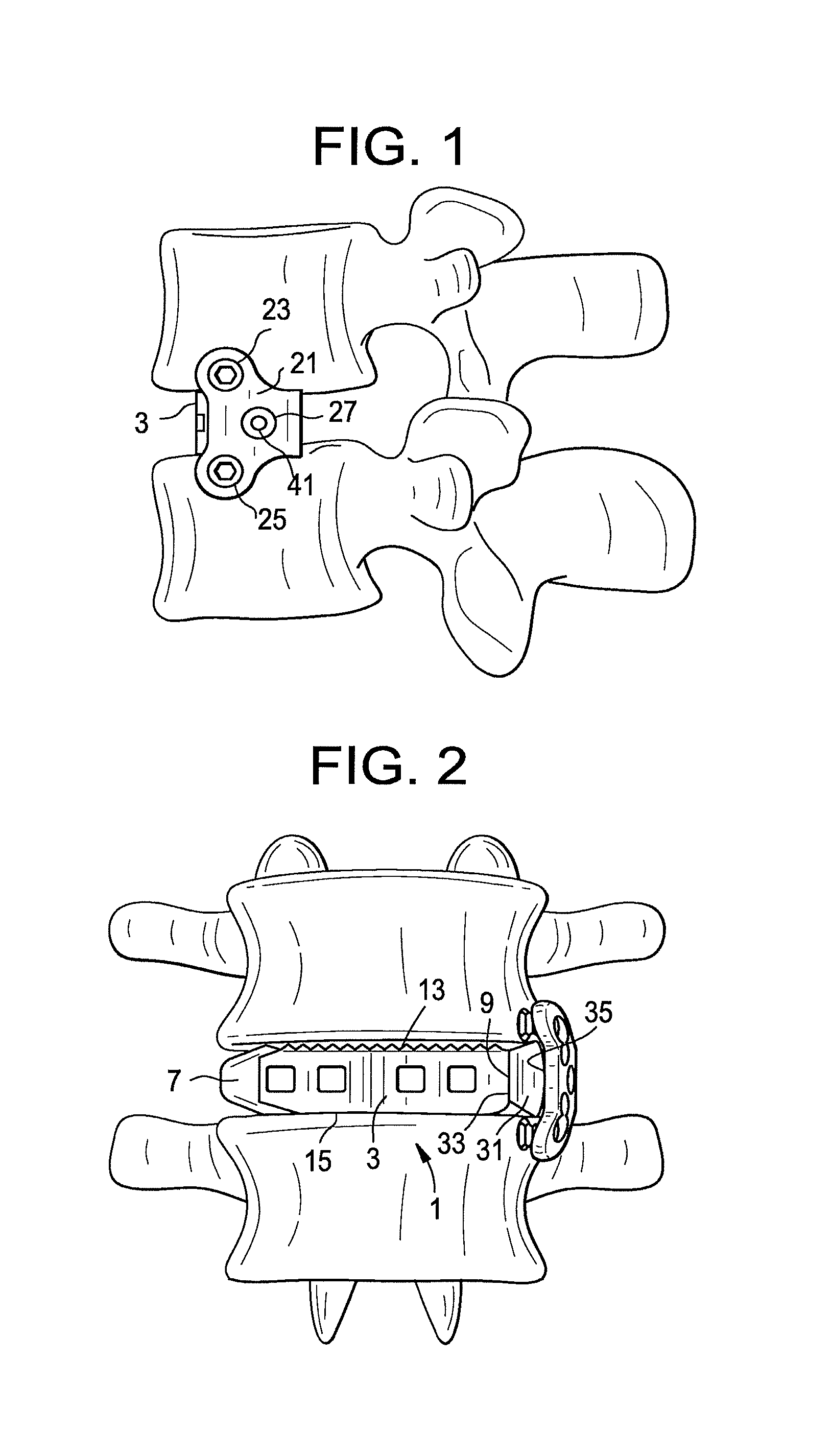
FIG. 1 shows a side view of a device of the present invention attached to sidewalls of adjacent vertebral bodies.
FIG. 2 shows a front view of a device of the present invention attached to sidewalls of adjacent vertebral bodies.
FIG. 3 shows a front view of a device of the present invention.
FIG. 4 shows a perspective view of a device of the present invention.
FIG. 5 shows a side view of a device of the present invention.
FIG. 6 shows a perspective view of a device of the present invention without its cage.
FIG. 7 discloses a perspective view of a first embodiment of a polyaxial assembly of the present invention.
FIG. 8 discloses a perspective view of the plate and nub components of the first embodiment of a polyaxial assembly of the present invention.
FIG. 9 shows a side view of the first embodiment of a polyaxial assembly of the present invention.
FIG. 10 shows a top view of the first embodiment of a polyaxial assembly of the present invention.
FIG. 11 discloses a cross-section view of a second embodiment of a polyaxial assembly of the present invention.
FIG. 12 shows a top view of a concave bone plate attached to a sidewall of a vertebral body.
FIG. 13 shows a side view of a concave bone plate attached to both sidewalls of adjacent vertebral bodies.
FIG. 14 discloses a side view of a conventional fusion device comprising an integral cage and plate.
FIG. 15 is a side view of a device of the present invention in which the nub and plate are integral.
FIG. 16 discloses a threaded post of the present invention.
FIG. 17 discloses a post of the present invention having a spherical head.
FIG. 18 discloses a side view of a conventional cage-plate assembly inserted in a disc space.
DETAILED DESCRIPTION OF THE INVENTION
Now referring to FIGS. 1-6, there is provided an intervertebral fusion device comprising:
a) an intervertebral fusion cage 1 having an anterior wall 3, a posterior wall 5, a leading wall 7 and a trailing wall 9 connecting the anterior and posterior walls to form a central vertical throughhole 11, an upper surface 13 adapted for gripping an upper endplate and a lower surface 15 adapted for gripping a lower endplate;
b) a bone plate 21 comprising an upper hole 23, a lower hole 25, and a central hole 27 disposed substantially between the first and second holes,
c) a nub 31 interposed between the bone plate and the trailing wall of the cage, the nub comprising: i) a first wall 33 contacting the trailing wall of the cage, ii) a second wall 35 contacting the bone plate, iii) a threaded throughhole 37 extending from the first wall to the second wall, and
d) a threaded post 41 received in the throughhole of the nub and passing through the central hole of the bone plate.
In some embodiments, the assembly has a polyaxial joint. It is believed that the inclusion of this polyaxial joint is very advantageous to the performance of the device. It has been noticed that typical variations in human physiology often result in a situation in which the sidewalls of the adjacent vertebrae that hold the plate are not coplanar with each other. Rather, one sidewall often extends out farther than its adjacent sidewall. Thus, when a conventional cage-plate assembly (in which the plate is rigidly attached to the cage in a perpendicular relationship) is used on a typical functional spinal unit, the lack of a coplanar relationship in the vertebral sidewalls leads to a fixation situation in which only one of the vertebral sidewalls will actually contact the plate. This asymmetrical contact undesirably leads to stress concentration and poor distribution of biomechanical forces (as one screw is loaded more), leading to bony fracture.
It is believed that a polyaxial joint in the cage-plate assembly alleviates these concerns. When the cage-plate assembly of the present invention is used on a typical functional spinal unit lacking coplanar vertebral sidewalls, the plate can be polyaxially adjusted about the cage until it contacts each of the sidewalls and then locked at that desired angle. This produces a fixation in which asymmetrical contact is eliminated.
Therefore, in accordance with the present invention, there is provided an intervertebral fusion device comprising:
a) an intervertebral fusion cage having an anterior wall, a posterior wall, leading and trailing walls connecting the anterior and posterior walls to form a central vertical throughhole, an upper surface adapted for gripping an upper endplate and a lower surface adapted for gripping a lower endplate, the upper and lower surface defining a cage height;
b) a bone plate comprising a bone contacting surface, and outer surface, upper and lower holes passing from the bone-contacting surface to the outer surface, and a projection extending distally from the bone contacting surface and having a height,
wherein the bone plate is connected to the trailing wall of the cage via a polyaxial connection.
Also in accordance with the present invention, there is provided an assembly device for fusing a disc space, comprising: [0051] a) a bone plate comprising a bone-contacting inner surface, an outer surface, upper and lower holes, a central hole, each hole passing from the outer surface to the inner surface, [0052] b) an intervertebral component comprising: [0053] i) a first wall facing the disc space, [0054] ii) a second wall contacting the inner surface of the bone plate, [0055] c) first and second bone anchors passing through the upper and lower holes of the bone plate, wherein the bone plate forms a polyaxial joint with the intervertebral component.
In a first polyaxial embodiment, and now referring to FIGS. 7, 8 and 10, the proximal head of the post comprises a spherical surface 43. This spherical surface can form a polyaxial joint with a mating spherical surface 45 formed in the central hole of the plate. Again, the polyaxial connection is advantageous for adjusting the orientation of the plate so that it evenly contacts both sidewalls of the adjacent vertebral bodies. Once the proper angulation is found, the post may be further threadably tightened into the nub to lock the desired angle.
Therefore, in accordance with the present invention, there is provided an interbody device for fusing a disc space, comprising:
a) a bone plate comprising a bone contacting inner surface, an outer surface, upper and lower holes, a central hole having a spherical surface thereon, each hole passing from the outer surface to the inner surface,
b) an intervertebral component comprising: i) a first wall facing the disc space, ii) a second wall contacting the inner surface of the bone plate, iii) a threaded throughhole extending from the first wall to the second wall,
c) first and second bone anchors passing through the upper and lower holes of the bone plate,
d) a post having a proximal spherical head and a distal threaded shaft,
wherein the inner surface of the bone plate contacts the second wall of the intervertebral component,
wherein the central hole of the bone plate and the threaded throughhole of the intervertebral component align,
wherein the distal threaded shaft of the post is threadably received in the threaded throughhole of the nub, and wherein the proximal spherical head of the post is received in the spherical surface of the central hole of the bone plate to form a polyaxial joint).
Now referring to FIGS. 7-10, in some embodiments in which the plate and post form a polyaxial joint, the second wall of the nub (which contacts the bone plate) has a convex surface 47. This convex surface is useful in the polyaxial joint embodiments of the present invention because it accommodates more tilting of the plate with respect to the nub while maintaining the joint.
Likewise, in some embodiments in which the plate and post form a polyaxial joint, the inner surface of the bone plate has a concave surface 49. This concave surface is useful in the polyaxial joint embodiments in which the second wall of the nub is convex because it accommodates more tilting of the plate with respect to the nub while maintaining the joint.
In some embodiments, and now referring to FIG. 9, the shaft 95 of the upper bone anchor 91 and the upper surface 13 of the cage define a first angle .alpha., the shaft 96 of the lower bone anchor 92 and the lower surface 15 of the cage define a second angle .beta., and the first angle .alpha. is not equal to second angle .beta.. This condition occurs when a polyaxial joint is created between the nub and bone plate, and the adjacent vertebral bodies do not align in a co-planar manner. In some embodiments thereof, the first angle .alpha. differs from second angle .beta. by at least 5 degrees.
In a second polyaxial preferred embodiment, and now referring to FIG. 11, the plate has an annular projection 51 extending distally from its inner surface 52 about the central hole, and the nub has a recessed surface 53 extending distally about its throughhole 54 from its second wall, so that the annular projection forms a polyaxial joint 55 with the recessed surface of the nub. The polyaxial nature of the connection between the plate and nub allows the plate to float over the nub. This ability to float facilitates the plate's fit upon vertebral body sidewall surfaces that are often not aligned in a coplanar manner. A post may be added to the assembly by passing it through the plate's central hole and attaching to the nub's throughhole. Now referring to FIG. 16, a thread 57 on the post's shaft 58 allows it to threadably mate with the throughhole of the nub, while a head 59 on the proximal end portion 61 of the post allows it to loosely retain the plate upon the nub. Thus the post acts to retain the plate on the nub while allowing the polyaxial connection to retain its ability to move. Once the desired angulation is achieved, the post may be further tightened upon the assembly to lock the desired angulation.
It is believed that the device of FIG. 11 represents the first polyaxial plate known to the present inventors.
Therefore, in accordance with the present invention, there is provided an interbody device for fusing a disc space, comprising:
a) a bone plate comprising a bone contacting inner surface, an outer surface, upper and lower holes, a central hole, each hole passing from the outer surface to the inner surface, and an annular projection extending distally from the inner surface about the central hole,
b) an intervertebral component comprising: i) a first wall facing the disc space, ii) a second wall contacting the inner surface of the bone plate, iii) a throughhole extending from the first wall to the second wall, iv) a recessed surface extending distally about the throughhole,
c) first and second bone anchors passing through the upper and lower holes of the bone plate,
wherein the annular projection of the bone plate forms a polyaxial joint with the recessed surface of the intervertebral component.
In general, the cage of the present invention can be any interbody fusion cage suitable for promoting fusion between two vertebral bodies. The cage can be adapted for lumbar, cervical or thoracic use. The cage can be adapted for lateral, posterior, or anterior insertion. In some preferred embodiments, the cage is adapted for lateral approach to the lumbar spine. Typically, the cage will have an anterior wall, a posterior wall, leading and trailing walls connecting the anterior and posterior walls to form a central vertical throughhole, an upper surface adapted for gripping an upper endplate and a lower surface adapted for gripping a lower endplate. The central vertical throughhole facilitates bone growth between the two adjacent vertebral endplates. Each of the posterior and anterior walls may have ventral-dorsal throughholes 62 therethrough in order to accommodate fusion as well. The leading wall of the lateral cage may have a bulleted nose 63 that eases insertion into the disc space.
The bone plate of the present invention typically comprises a bone-contacting inner surface, an outer surface, and upper and lower holes passing from the bone-contacting surface to the outer surface. Bone anchors pass through these upper and lower holes to thereby anchor the plate to the adjacent vertebral bodies.
In some embodiments, and now referring to FIGS. 7, 8, and 10, the central hole of the plate (into which the post seats) opens laterally onto a sidewall 65 of the plate. The purpose of this lateral opening is to allow a snap-fit assembly. It is believed that when this opening constitutes about 40% of the central hole periphery, the snap fit will be sufficiently robust so as to hold plate on the post.
In some embodiments, the central hole in the plate is provided in the form of an elongated slot. The elongated slot allows for slidable adjustment of the plate upon the nub, thereby allowing for a fine tuning of the plate location after the nub location is set.
In some embodiments, the bone-contacting inner surface of the plate narrows distally. This contouring helps the plate fit between the adjacent vertebrae. This feature is believed to be advantageous in MIS procedures in which the components are inserted into the spinal area through a tube in the absence of a clear line of sight on the part of the surgeon.
In some embodiments, as in FIG. 13, the outer surface 67 of the bone plate is convex. This condition helps the plate conform to the convex bony surfaces of the adjacent vertebrae.
In some embodiments, as in FIG. 12, the bone-contacting inner surface 69 of the bone plate is concave. This condition helps the plate conform to the convex bony surfaces of the adjacent vertebrae.
In some embodiments, as in FIG. 3, the inner surface of the plate further comprises a radius 201 and a projection 203. This radius advantageously matches the contour of the vertebral body in this region.
As discussed above, the purpose of the nub is to prevent undesired pivoting of the plate about its centerpoint.
In some embodiments, the cage, plate and nub are present as separate components. This condition maximizes the surgeon's ability to adjust the location of the plate after fixing the locations of the cage and nub.
In some embodiments, and now referring to FIG. 15, the nub and plate are an integral component 71 that is separate from the cage 73.
Therefore, in accordance with the present invention, there is provided an intervertebral fusion device comprising:
a) an intervertebral fusion cage having an anterior wall, a posterior wall, leading and trailing walls connecting the anterior and posterior walls to form a central vertical throughhole, an upper surface adapted for gripping an upper endplate and a lower surface adapted for gripping a lower endplate,
b) a separate bone plate component comprising a bone contacting surface, and outer surface, upper and lower holes passing from the bone-contacting surface to the outer surface, and a projection extending distally from the bone contacting surface,
wherein the projection of the bone plate contacts the trailing wall of the cage. In some embodiments, and now referring to FIGS. 7 and 8, the nub further comprises: iii) an upper surface adapted for gripping an upper endplate, and iv) a lower surface adapted for gripping a lower endplate
wherein each of the upper and lower surfaces of the nub is disposed between the first and second walls of the nub.
In preferred embodiments, gripping is accomplished by providing a plurality of teeth 75 upon each of the upper and lower surfaces. The purpose of these nub teeth is to enhance the snug fit of the nub between the vertebral bodies and thereby further prevent the rocking of the plate.
In some embodiments, and now referring to FIG. 3, the upper surface and lower surface of the cage define a cage height, and the lower surface and upper surface of the nub define a nub height, and wherein the nub height HN is not greater than the cage height Hc. This condition enhances the ability of the surgeon to transport the nub down the same MIS tube as the cage.
In some embodiments, the nub height is not less than the cage height. This condition enhances the snug fit of the nub between the vertebral bodies and thereby further prevent the rocking of the plate.
In some embodiments, the nub height is substantially the same as the cage height. This condition possess the attributes of the two conditions described above.
In some embodiments, and now referring to FIG. 3, the nub narrows distally. This contouring helps the nub locate the hole in the annulus through which the cage has been placed. This feature is believed to be advantageous in MIS procedures in which the components are inserted into the spinal area through a tube without the surgeon having a clear line of sight.
The function of the post is to retain the plate on the nub. Typically, and now referring to FIGS. 16 and 17, the post has a threaded distal end portion adapted for threadable mating to the central hole of the nub. In some embodiments, the post has a proximal end portion forming an enlarged head. In some embodiments thereof, the proximal head 81 has a spherical portion 83.
Typically, the post passes through the central hole of the plate and threads into the nub. However, in some embodiments, the post can thread into the cage as well.
Generally, and now referring to FIGS. 3 and 9, the device of the present invention also comprises upper and lower bone anchors 91,92 received in the respective upper and lower holes, each bone anchor having a proximal head 93,94 and a distal shaft 95,96. Preferably, the bone anchor is a screw that has a threaded shaft 97,98.
Generally, and now referring to FIGS. 5 and 6, the device of the present invention also comprises first and second cams 101 threadably received in the respective threaded recesses 103 of the bone plate and bearing against the respective heads of the bone anchors. These cams tighten against the heads of the screws, thereby preventing screw backout.
The cages of the present invention may be made from any non-resorbable material appropriate for human surgical implantation, including but not limited to, surgically appropriate metals, and non-metallic materials, such as carbon fiber composites, polymers and ceramics.
The interbody devices are preferably made out of PEEK or CFRP or any other suitable material providing adequate strength and radiolucency. However, implantable metals such as titanium or stainless steel components may be required to ensure adequate strength for either the interbody device. In some cases the interbody device can be made as a combination of PEEK and metal. In some cases, resorbable materials such as polylactide, polyglycolide, and magnesium are preferred.
In some embodiments, the cage material is selected from the group consisting of PEEK, ceramic and metallic. The cage material is preferably selected from the group consisting of metal and composite (such as PEEK/carbon fiber).
If a metal is chosen as the material of construction for a component, then the metal is preferably selected from the group consisting of titanium, titanium alloys (such as Ti-6Al-4V), chrome alloys (such as CrCo or Cr--Co--Mo) and stainless steel.
If a polymer is chosen as a material of construction for a component, then the polymer is preferably selected from the group consisting of polyesters, (particularly aromatic esters such as polyalkylene terephthalates, polyamides; polyalkenes; poly(vinyl fluoride); PTFE; polyarylethyl ketone PAEK; polyphenylene and mixtures thereof.
If a ceramic is chosen as the material of construction for a component, then the ceramic is preferably selected from the group consisting of alumina, zirconia and mixtures thereof. It is preferred to select an alumina-zirconia ceramic, such as BIOLOX Delta.TM., available from CeramTec of Plochingen, Germany.
In some embodiments, the cage member comprises PEEK. In others, it is a ceramic.
In some embodiments, the first component consists essentially of a metallic material, preferably a titanium alloy or a chrome-cobalt alloy.
In some embodiments, the components are made of a stainless steel alloy, preferably BioDur.RTM. CCM Plus.RTM. Alloy available from Carpenter Specialty Alloys, Carpenter Technology Corporation of Wyomissing, Pa. In some embodiments, the outer surfaces of the components are coated with a sintered beadcoating, preferably Porocoat.TM., available from DePuy Orthopaedics of Warsaw, Ind.
In some embodiments, the components are made from a composite comprising carbon fiber. Composites comprising carbon fiber are advantageous in that they typically have a strength and stiffness that is superior to neat polymer materials such as a polyarylethyl ketone PAEK. In some embodiments, each component is made from a polymer composite such as a PEKK-carbon fiber composite.
Preferably, the composite comprising carbon fiber further comprises a polymer. Preferably, the polymer is a polyarylethyl ketone (PAEK). More preferably, the PAEK is selected from the group consisting of polyetherether ketone (PEEK), polyether ketone ketone (PEKK) and polyether ketone (PEK). In preferred embodiments, the PAEK is PEEK.
In some embodiments, the carbon fiber comprises between 1 vol % and 60 vol % (more preferably, between 10 vol % and 50 vol %) of the composite. In some embodiments, the polymer and carbon fibers are homogeneously mixed. In others, the material is a laminate. In some embodiments, the carbon fiber is present in a chopped state. Preferably, the chopped carbon fibers have a median length of between 1 mm and 12 mm, more preferably between 4.5 mm and 7.5 mm. In some embodiments, the carbon fiber is present as continuous strands.
In especially preferred embodiments, the composite comprises: [0119] 40-99% (more preferably, 60-80 vol %) polyarylethyl ketone (PAEK), and [0120] 1-60% (more preferably, 20-40 vol %) carbon fiber, wherein the polyarylethyl ketone (PAEK) is selected from the group consisting of polyetherether ketone (PEEK), polyether ketone ketone (PEKK) and polyether ketone (PEK).
In some embodiments, the composite consists essentially of PAEK and carbon fiber. More preferably, the composite comprises 60-80 wt % PAEK and 20-40 wt % carbon fiber. Still more preferably the composite comprises 65-75 wt % PAEK and 25-35 wt % carbon fiber.
In some embodiments, the post and screw components of the present invention are made from a biocompatible metal, such as stainless steel, chromium cobalt, or titanium alloy.
In some embodiments, the plates of the present invention are made from a biocompatible metal, such as stainless steel, chromium cobalt, or titanium alloy.
Although the present invention has been described with reference to its preferred embodiments, those skillful in the art will recognize changes that may be made in form and structure which do not depart from the spirit of the invention.
In some embodiments, the central throughhole of the cage is filled with a fusion material. This fusion material promotes bony fusion of the adjacent vertebral bodies through the disc space. In some embodiments, the fusion material may be autograft bone marrow or allograft bone. In some embodiments, the fusion material may be synthetic, such as tricalcium phosphate or hydroxyapatite. In some embodiments, the fusion material may be a recombinant protein, such as a growth factor.
Implant Placement without a Plate Cage Connection
After successfully accessing, clearing and sizing the disc space, select the corresponding implant, fill the cage implant with autogenous bone graft material and attach to the inserter. Gently impact the cage implant into the disc space while monitoring placement under AP fluoroscopy. Ideal placement of the implant is to support the endplate medial/laterally to the contra-lateral rim and between the anterior third and middle third of the disc space from an anterior/posterior perspective.
Select the appropriate nubbed plate implant based on morphology and cage size, attach it to its respective inserter. Using the cage as a guide, insert the plate until the nubbed portion is within the disc space supporting the vertebral body rim and the plate portion abuts the ipsilateral walls of the superior and inferior vertebral bodies. The nubbed plate can be slightly repositioned from the cage location anteriorly or posteriorly in order to optimize the screw location or to account for anomalies such as osteophytes or a slightly compromised cage trajectory.
Attach the plate with the appropriate anchors.
Implant Placement with the Plate and Cage Connected
After successfully accessing, clearing and sizing the disc space, select the corresponding implant, fill the cage portion with autogenous bone graft material and attach the plate-cage combination to the inserter. Gently impact the implant into the disc space while monitoring placement under AP fluoroscopy. Ideal placement of the implant is for the cage portion to support the endplate medial/laterally to the contra-lateral rim and for the nubbed portion to support the ipsilateral rim while the plate portion is in contact with the walls of the superior and inferior vertebral bodies. The implant should be between the anterior third and middle third of the disc space from an anterior/posterior perspective.
The nubbed plate portion can only be slightly repositioned from the cage based on the extent of the polyaxial/sliding connection between the plate and nubbed portion. This allows for a diminished ability to accommodate morphological or surgical anomalies but increases the ergonomics of the surgery by reducing it to a single insertion technique.
Attach the plate with the appropriate anchors.
In some embodiments, the nub supports the ipsilateral rim of the vertebral body and the cage supports the contralateral rim of the vertebral body.
* * * * *
D00000
D00001
D00002
D00003
D00004
D00005
D00006
D00007
XML
uspto.report is an independent third-party trademark research tool that is not affiliated, endorsed, or sponsored by the United States Patent and Trademark Office (USPTO) or any other governmental organization. The information provided by uspto.report is based on publicly available data at the time of writing and is intended for informational purposes only.
While we strive to provide accurate and up-to-date information, we do not guarantee the accuracy, completeness, reliability, or suitability of the information displayed on this site. The use of this site is at your own risk. Any reliance you place on such information is therefore strictly at your own risk.
All official trademark data, including owner information, should be verified by visiting the official USPTO website at www.uspto.gov. This site is not intended to replace professional legal advice and should not be used as a substitute for consulting with a legal professional who is knowledgeable about trademark law.