Methods and devices for pain management
Allison , et al.
U.S. patent number 10,314,739 [Application Number 15/045,797] was granted by the patent office on 2019-06-11 for methods and devices for pain management. This patent grant is currently assigned to MyoScience, Inc.. The grantee listed for this patent is MyoScience, Inc.. Invention is credited to John Allison, Richard Radnovich, Jason Reynolds.


View All Diagrams
| United States Patent | 10,314,739 |
| Allison , et al. | June 11, 2019 |
Methods and devices for pain management
Abstract
A method in which a location is determined on the skin that is proximate to a sensory nerve that is associated with a painful condition. At least one needle of a cryogenic device is inserted into the location on the skin such that the needle is proximate to the sensory nerve. The device is activated such that the at least one needle creates a cooling zone about the sensory nerve, thereby eliminating or reducing severity of the painful condition.
| Inventors: | Allison; John (Los Altos, CA), Radnovich; Richard (Boise, ID), Reynolds; Jason (Santa Rosa, CA) | ||||||||||
|---|---|---|---|---|---|---|---|---|---|---|---|
| Applicant: |
|
||||||||||
| Assignee: | MyoScience, Inc. (Fremont,
CA) |
||||||||||
| Family ID: | 51530769 | ||||||||||
| Appl. No.: | 15/045,797 | ||||||||||
| Filed: | February 17, 2016 |
Prior Publication Data
| Document Identifier | Publication Date | |
|---|---|---|
| US 20160166429 A1 | Jun 16, 2016 | |
Related U.S. Patent Documents
| Application Number | Filing Date | Patent Number | Issue Date | ||
|---|---|---|---|---|---|
| 14025527 | Sep 12, 2013 | 9295512 | |||
| 61800478 | Mar 15, 2013 | ||||
| 61801268 | Mar 15, 2013 | ||||
| Current U.S. Class: | 1/1 |
| Current CPC Class: | A61M 5/00 (20130101); A61F 7/12 (20130101); A61B 18/02 (20130101); A61N 1/403 (20130101); A61B 2018/00041 (20130101); A61F 2007/0042 (20130101); A61M 2202/0484 (20130101); A61F 2007/0285 (20130101); A61M 2210/086 (20130101); A61B 2018/00434 (20130101); A61F 2007/0087 (20130101); A61B 2018/0293 (20130101); A61B 2018/1425 (20130101) |
| Current International Class: | A61B 18/02 (20060101); A61M 5/00 (20060101); A61F 7/12 (20060101); A61N 1/40 (20060101); A61F 7/02 (20060101); A61B 18/14 (20060101); A61B 18/00 (20060101); A61F 7/00 (20060101) |
References Cited [Referenced By]
U.S. Patent Documents
| 2319542 | May 1943 | Hall |
| 2672032 | March 1964 | Towse |
| 3266492 | August 1966 | Steinberg |
| 3289424 | December 1966 | Shepherd |
| 3343544 | September 1967 | Dunn et al. |
| 3351063 | November 1967 | Malaker et al. |
| 3439680 | April 1969 | Thomas, Jr. |
| 3483869 | December 1969 | Hayhurst |
| 3502081 | March 1970 | Amoils |
| 3507283 | April 1970 | Thomas, Jr. |
| 3532094 | October 1970 | Stahl |
| 3664344 | May 1972 | Bryne |
| 3702114 | November 1972 | Zacarian |
| 3795245 | March 1974 | Allen, Jr. et al. |
| 3814095 | June 1974 | Lubens |
| 3830239 | August 1974 | Stumpf et al. |
| 3886945 | June 1975 | Stumpf et al. |
| 3889681 | June 1975 | Waller et al. |
| 3951152 | April 1976 | Crandell et al. |
| 3993075 | November 1976 | Lisenbee et al. |
| 4140109 | February 1979 | Savic et al. |
| 4207897 | June 1980 | Lloyd et al. |
| 4236518 | December 1980 | Floyd |
| 4306568 | December 1981 | Torre |
| 4376376 | March 1983 | Gregory |
| 4404862 | September 1983 | Harris, Sr. |
| 4524771 | June 1985 | McGregor et al. |
| 4758217 | July 1988 | Gueret |
| 4802475 | February 1989 | Weshahy |
| 4946460 | August 1990 | Merry et al. |
| 5059197 | October 1991 | Urie et al. |
| 5200170 | April 1993 | McDow |
| 5294325 | March 1994 | Liu |
| 5334181 | August 1994 | Rubinsky et al. |
| 5520681 | May 1996 | Fuller et al. |
| 5571147 | November 1996 | Sluijter et al. |
| 5647868 | July 1997 | Chinn |
| 5747777 | May 1998 | Matsuoka |
| 5755753 | May 1998 | Knowlton |
| 5814040 | September 1998 | Nelson et al. |
| 5860970 | January 1999 | Goddard et al. |
| 5879378 | March 1999 | Usui |
| 5899897 | May 1999 | Rabin et al. |
| 5916212 | June 1999 | Baust et al. |
| 5976505 | November 1999 | Henderson |
| 6003539 | December 1999 | Yoshihara |
| 6032675 | March 2000 | Rubinsky |
| 6039730 | March 2000 | Rabin et al. |
| 6041787 | March 2000 | Rubinsky |
| 6139545 | October 2000 | Utley et al. |
| 6141985 | November 2000 | Cluzeau et al. |
| 6142991 | November 2000 | Schatzberger |
| 6182666 | February 2001 | Dobak, III |
| 6196839 | March 2001 | Ross |
| 6238386 | May 2001 | Muller et al. |
| 6277099 | August 2001 | Strowe et al. |
| 6277116 | August 2001 | Utely et al. |
| 6363730 | April 2002 | Thomas et al. |
| 6371943 | April 2002 | Racz et al. |
| 6432102 | August 2002 | Joye et al. |
| 6494844 | December 2002 | Van Bladel et al. |
| 6503246 | January 2003 | Har-shai et al. |
| 6506796 | January 2003 | Fesus et al. |
| 6546935 | April 2003 | Hooven |
| 6551309 | April 2003 | LePivert |
| 6562030 | May 2003 | Abboud et al. |
| 6629951 | October 2003 | Laufer et al. |
| 6648880 | November 2003 | Chauvet et al. |
| 6669688 | December 2003 | Svaasand et al. |
| 6672095 | January 2004 | Luo |
| 6682501 | January 2004 | Nelson et al. |
| 6706037 | March 2004 | Zvuloni et al. |
| 6723092 | April 2004 | Brown et al. |
| 6749624 | June 2004 | Knowlton |
| 6761715 | July 2004 | Carroll |
| 6764493 | July 2004 | Weber et al. |
| 6786901 | September 2004 | Joye et al. |
| 6786902 | September 2004 | Rabin et al. |
| 6789545 | September 2004 | Littrup et al. |
| 6840935 | January 2005 | Lee |
| 6858025 | February 2005 | Maurice |
| 6902554 | June 2005 | Huttner |
| 6905492 | June 2005 | Zvuloni et al. |
| 6960208 | November 2005 | Bourne et al. |
| 7001400 | February 2006 | Modesitt et al. |
| 7081111 | July 2006 | Svaasand et al. |
| 7081112 | July 2006 | Joye et al. |
| 7083612 | August 2006 | Littrup et al. |
| 7195616 | March 2007 | Diller et al. |
| 7217939 | May 2007 | Johansson et al. |
| 7250046 | July 2007 | Fallat |
| 7311672 | December 2007 | Van Bladel et al. |
| 7367341 | May 2008 | Anderson et al. |
| 7402140 | July 2008 | Spero et al. |
| 7422586 | September 2008 | Morris et al. |
| 7507234 | March 2009 | Utley et al. |
| 7578819 | August 2009 | Bleich et al. |
| 7641679 | January 2010 | Joye et al. |
| 7653438 | January 2010 | Deem |
| 7713266 | May 2010 | Elkins et al. |
| 7850683 | December 2010 | Elkins et al. |
| 7862558 | January 2011 | Elkins et al. |
| 7998137 | August 2011 | Elkins et al. |
| 8027718 | September 2011 | Spinner et al. |
| 8298216 | October 2012 | Burger et al. |
| 8409185 | April 2013 | Burger et al. |
| 8617228 | December 2013 | Coulombe et al. |
| 8715275 | May 2014 | Burger et al. |
| 8722065 | May 2014 | Ishibashi et al. |
| 9039688 | May 2015 | Palmer, III et al. |
| 9295512 | March 2016 | Allison |
| 2002/0010460 | January 2002 | Joye et al. |
| 2002/0013602 | January 2002 | Huttner |
| 2002/0045434 | April 2002 | Masoian et al. |
| 2002/0049436 | April 2002 | Zvuloni et al. |
| 2002/0068929 | June 2002 | Zvuloni |
| 2002/0095144 | July 2002 | Carl |
| 2002/0120260 | August 2002 | Morris et al. |
| 2002/0120261 | August 2002 | Morris et al. |
| 2002/0120263 | August 2002 | Brown et al. |
| 2002/0128638 | September 2002 | Chauvet et al. |
| 2002/0156469 | October 2002 | Yon et al. |
| 2002/0183731 | December 2002 | Holland et al. |
| 2002/0193778 | December 2002 | Alchas et al. |
| 2003/0036752 | February 2003 | Joye et al. |
| 2003/0109912 | June 2003 | Joye et al. |
| 2003/0130575 | July 2003 | Desai |
| 2003/0144709 | July 2003 | Zabara |
| 2003/0181896 | September 2003 | Zvuloni et al. |
| 2003/0195436 | October 2003 | Van Bladel et al. |
| 2003/0220635 | November 2003 | Knowlton et al. |
| 2003/0220674 | November 2003 | Anderson et al. |
| 2004/0024391 | February 2004 | Cytron et al. |
| 2004/0082943 | April 2004 | Littrup et al. |
| 2004/0092875 | May 2004 | Kochamba |
| 2004/0122482 | June 2004 | Tung et al. |
| 2004/0143252 | July 2004 | Hurst |
| 2004/0162551 | August 2004 | Brown et al. |
| 2004/0167505 | August 2004 | Joye et al. |
| 2004/0191229 | September 2004 | Link, Jr. et al. |
| 2004/0204705 | October 2004 | Lafontaine et al. |
| 2004/0210212 | October 2004 | Maurice |
| 2004/0215178 | October 2004 | Maurice |
| 2004/0215294 | October 2004 | Littrup et al. |
| 2004/0215295 | October 2004 | Littrup et al. |
| 2004/0220497 | November 2004 | Findlay et al. |
| 2004/0220648 | November 2004 | Carroll |
| 2004/0225276 | November 2004 | Burgess |
| 2004/0243116 | December 2004 | Joye et al. |
| 2004/0267248 | December 2004 | Duong et al. |
| 2004/0267257 | December 2004 | Bourne et al. |
| 2005/0004563 | January 2005 | Racz et al. |
| 2005/0177147 | August 2005 | Vancelette et al. |
| 2005/0177148 | August 2005 | van der Walt et al. |
| 2005/0182394 | August 2005 | Spero et al. |
| 2005/0203505 | September 2005 | Megerman et al. |
| 2005/0203593 | September 2005 | Shanks et al. |
| 2005/0209565 | September 2005 | Yuzhakov et al. |
| 2005/0209587 | September 2005 | Joye et al. |
| 2005/0224086 | October 2005 | Nahon |
| 2005/0228288 | October 2005 | Hurst |
| 2005/0251103 | November 2005 | Steffen et al. |
| 2005/0261753 | November 2005 | Littrup et al. |
| 2005/0276759 | December 2005 | Roser et al. |
| 2005/0281530 | December 2005 | Rizoiu et al. |
| 2005/0283148 | December 2005 | Janssen et al. |
| 2006/0009712 | January 2006 | Van Bladel et al. |
| 2006/0015092 | January 2006 | Joye et al. |
| 2006/0069385 | March 2006 | Lafontaine et al. |
| 2006/0079914 | April 2006 | Modesitt et al. |
| 2006/0084962 | April 2006 | Joye et al. |
| 2006/0089688 | April 2006 | Panescu |
| 2006/0111732 | May 2006 | Gibbens et al. |
| 2006/0129142 | June 2006 | Reynolds |
| 2006/0142785 | June 2006 | Modesitt et al. |
| 2006/0173469 | August 2006 | Klein et al. |
| 2006/0189968 | August 2006 | Howlett et al. |
| 2006/0190035 | August 2006 | Hushka et al. |
| 2006/0200117 | September 2006 | Hermans |
| 2006/0212028 | September 2006 | Joye et al. |
| 2006/0212048 | September 2006 | Crainich |
| 2006/0223052 | October 2006 | MacDonald et al. |
| 2006/0224149 | October 2006 | Hillely |
| 2006/0258951 | November 2006 | Bleich et al. |
| 2007/0060921 | March 2007 | Janssen et al. |
| 2007/0088217 | April 2007 | Babaev |
| 2007/0129714 | June 2007 | Elkins et al. |
| 2007/0156125 | July 2007 | DeLonzor |
| 2007/0161975 | July 2007 | Goulko |
| 2007/0167943 | July 2007 | Janssen et al. |
| 2007/0167959 | July 2007 | Modesitt et al. |
| 2007/0179509 | August 2007 | Nagata et al. |
| 2007/0198071 | August 2007 | Ting et al. |
| 2007/0225781 | September 2007 | Saadat |
| 2007/0255362 | November 2007 | Levinson et al. |
| 2007/0270925 | November 2007 | Levinson |
| 2008/0051775 | February 2008 | Evans |
| 2008/0051776 | February 2008 | Bliweis et al. |
| 2008/0077201 | March 2008 | Levinson et al. |
| 2008/0077202 | March 2008 | Levinson |
| 2008/0077211 | March 2008 | Levinson et al. |
| 2008/0154254 | June 2008 | Burger et al. |
| 2008/0183164 | July 2008 | Elkins et al. |
| 2008/0200910 | August 2008 | Burger et al. |
| 2008/0287839 | November 2008 | Rosen et al. |
| 2009/0018623 | January 2009 | Levinson et al. |
| 2009/0018624 | January 2009 | Levinson et al. |
| 2009/0018625 | January 2009 | Levinson et al. |
| 2009/0018626 | January 2009 | Levinson et al. |
| 2009/0018627 | January 2009 | Levinson et al. |
| 2009/0118722 | May 2009 | Ebbers et al. |
| 2009/0171334 | July 2009 | Elkins et al. |
| 2009/0248001 | October 2009 | Burger et al. |
| 2009/0264876 | October 2009 | Roy et al. |
| 2009/0299357 | December 2009 | Zhou |
| 2010/0114191 | May 2010 | Newman |
| 2010/0168725 | July 2010 | Babkin et al. |
| 2010/0305439 | December 2010 | Shai et al. |
| 2010/0331883 | December 2010 | Schmitz et al. |
| 2011/0144631 | June 2011 | Elkins et al. |
| 2011/0178514 | July 2011 | Levin et al. |
| 2011/0196267 | August 2011 | Mishelevich |
| 2012/0065629 | March 2012 | Elkins et al. |
| 2012/0089211 | April 2012 | Curtis et al. |
| 2012/0165715 | June 2012 | Murphy |
| 2012/0259322 | October 2012 | Fourkas et al. |
| 2012/0265187 | October 2012 | Palmer, III et al. |
| 2013/0253605 | September 2013 | Bennett |
| 2013/0261368 | October 2013 | Schwartz |
| 2013/0324990 | December 2013 | Burger et al. |
| 2014/0249519 | September 2014 | Burger et al. |
| 2014/0276539 | September 2014 | Allison et al. |
| 2014/0276708 | September 2014 | Karnik et al. |
| 2014/0343542 | November 2014 | Karnik et al. |
| 2014/0343543 | November 2014 | Karnik et al. |
| 2014/0343544 | November 2014 | Carnell et al. |
| 2017/0258510 | September 2017 | Carnell et al. |
| 2643474 | Sep 2007 | CA | |||
| 43447 | Jan 1982 | EP | |||
| 777123 | Jun 1997 | EP | |||
| 955012 | Nov 1999 | EP | |||
| 1074273 | Feb 2001 | EP | |||
| 1377327 | Sep 2007 | EP | |||
| 1862125 | Dec 2007 | EP | |||
| 2499984 | Sep 2012 | EP | |||
| 1360353 | Jul 1974 | GB | |||
| 1402632 | Aug 1975 | GB | |||
| 60013111 | Jan 1985 | JP | |||
| 04357945 | Dec 1992 | JP | |||
| 05038347 | Feb 1993 | JP | |||
| 10014656 | Jan 1998 | JP | |||
| 2001178737 | Jul 2001 | JP | |||
| 2005080988 | Mar 2005 | JP | |||
| 2006130055 | May 2006 | JP | |||
| 2008515469 | May 2008 | JP | |||
| 2254060 | Jun 2005 | RU | |||
| 9749344 | Dec 1997 | WO | |||
| 0197702 | Dec 2001 | WO | |||
| 0202026 | Jan 2002 | WO | |||
| 02092153 | Nov 2002 | WO | |||
| 2004039440 | May 2004 | WO | |||
| 2004045434 | Jun 2004 | WO | |||
| 2004089460 | Oct 2004 | WO | |||
| 2005000106 | Jan 2005 | WO | |||
| 2005079321 | Sep 2005 | WO | |||
| 2005096979 | Oct 2005 | WO | |||
| 2006012128 | Feb 2006 | WO | |||
| 2006023348 | Mar 2006 | WO | |||
| 2006044727 | Apr 2006 | WO | |||
| 2006062788 | Jun 2006 | WO | |||
| 2006125835 | Nov 2006 | WO | |||
| 2006127467 | Nov 2006 | WO | |||
| 2007025106 | Mar 2007 | WO | |||
| 2007037326 | Apr 2007 | WO | |||
| 2007089603 | Aug 2007 | WO | |||
| 2007109656 | Sep 2007 | WO | |||
| 2007129121 | Nov 2007 | WO | |||
| 2007135629 | Nov 2007 | WO | |||
| 2009026471 | Feb 2009 | WO | |||
| 2010075438 | Jul 2010 | WO | |||
| 2010075448 | Jul 2010 | WO | |||
| 2014146105 | Sep 2014 | WO | |||
| 2014146106 | Sep 2014 | WO | |||
| 2014146122 | Sep 2014 | WO | |||
| 2014146127 | Sep 2014 | WO | |||
| 2014146105 | Nov 2014 | WO | |||
| 2014146106 | Dec 2014 | WO | |||
Other References
|
"Cryoablation in Pain Management brochure," Metrum CryoFlex, 2012, 5 pages. cited by applicant . "Cryosurgery probes and accessories catalogue," Metrum CryoFlex, 2009, 25 pages. cited by applicant . Advanced Cosmetic Intervention, "New Technology Targets Motor Nerves," [webpage], retrieved from the Internet: <<http://www.acisurgery.com>> copyright 2007, 1 page. cited by applicant . Bohannon et al., "Interrater reliability of a modified Ashworth scale of muscle spasticity," Phys Ther., vol. 67, No. 2, Feb. 1987, pp. 206-207. cited by applicant . Boyd et al., "Objective measurement of clinical findings in the use of botulinum toxin type A for the management of children with cerebral palsy," European Journal of Neurology, vol. 6, Supp. S4, 1999, pp. S23-S35. cited by applicant . Cryopen, LLC, "CyroPen, LLC Launches Revolutionary, State-of-the-Art Medical Device--The Dure of Cryosurgery in a Pend", retrieved from the Internet: <<http://cryopen.com/press.htm>>, Apr. 27, 2007, 3 pages. cited by applicant . Cryopen, LLC., "The future of Cryosurgery at your fingertips", retrieved from the Internet: <<http://cryopen.com/>> copyright 2006-2008, 2 pages. cited by applicant . Cryosurgical Concepts, Inc., "CryoProbe.TM.--Excellence in Cryosurgery", retrieved from the Internet: <<http://www.cryo-surgical.com//>>, Feb. 8, 2008, 2 pages. cited by applicant . Dasiou-Plankida, "Fat injections for facial rejuvenation: 17 years experience in 1720 patients", Journal of Cosmetic Dermatology, vol. 2, Issue 3-4, Oct. 22, 2004, pp. 119-125. cited by applicant . Farrar et al., "Validity, reliability, and clinical importance of change in a 0-10 numeric rating scale measure of spasticity: a post hoc analysis of a randomized, double-blind, placebo-controlled trial", Clin Ther., vol. 30, No. 5, 2008, pp. 974-985. cited by applicant . Foster et al., "Radiofrequency Ablation of Facial Nerve Branches Controlling Glabellar Frowning", Dermatol Surg, vol. 35, issue 12, Dec. 2009, pp. 1908-1917. cited by applicant . Gallagher et al., "Prospective validation of clinically important changes in pain severity measured on a visual analog scale", Annals of Emergency Medicine, vol. 38, No. 6, 2001, pp. 633-638. cited by applicant . Har-Shai et al., "Effect of skin surface temperature on skin pigmentation during contact and intralesional cryosurgery of hypertrophic scars and Kleoids", Journal of the European Academy of Dermatology and Venereology, vol. 21, Issue 2, Feb. 2007, pp. 191-198. cited by applicant . Magalov et al., "Isothermal volume contours generated in a freezing gel by embedded cryo-needles with applications to cryo-surgery", Cryobiology, vol. 55, Issue 2, Oct. 2007, pp. 127-137. cited by applicant . Morris, "Ashworth and Tardieu Scales: Their Clinical Relevance for Measuring Spasticity in Adult and Pediatric Neurological Populations", Physical Therapy Reviews, vol. 7, No. 1, 2002, pp. 53-62. cited by applicant . One Med Group, LLC., "CryoProbeTM", [webpage] retrieved from the internet: <http://www.onemedgroup.com//>, Feb. 4, 2008, 2 pages. cited by applicant . Page et al., "Clinically important differences for the upper-extremity Fugl-Meyer Scale in people with minimal to moderate impairment due to chronic stroke", Physical Therapy, vol. 92, No. 6, 2012, pp. 791-798. cited by applicant . Penn et al., "Intrathecal baclofen for severe spinal spasticity", N Engl J Med., vol. 320, No. 23, Jun. 8, 1989, pp. 1517-1521. cited by applicant . Rewcastle et al., "A model for the time dependent three-dimensional thermal distribution within iceballs surrounding multiple cryoprobes", Medical Physics, vol. 28, Issue 6, Jun. 2001, pp. 1125-1137. cited by applicant . Rutkove, "Effects of temperature on neuromuscular electrophysiology", Muscles and Nerves, vol. 24, Issue 7, Jun. 12, 2001, pp. 867-882. cited by applicant . Shaw et al., "BoTULS: a multicentre randomised controlled trial to evaluate the clinical effectiveness and cost-effectiveness of treating upper limb spasticity due to stroke with botulinum toxin type A", Health Technol Assess., vol. 14, No. 26, 2010, 158 pages. cited by applicant . Sullivan et al., "Fugl-Meyer assessment of sensorimotor function after stroke: standardized training procedure for clinical practice and clinical trials", Stroke, vol. 42, No. 2, 2011, pp. 427-432. cited by applicant . Utley et al., "Radiofrequency ablation of the nerve to the corrugator muscle for elimination of glabellar furrowing", Archives of Facial Plastic Surgery, vol. 1, No. 1, Jan. 1999, pp. 46-48. cited by applicant . Yang et al., "Apoptosis induced by cryo-injury in human colorectal cancer cells is associated with mitochondrial dysfunction", International Journal of Cancer, vol. 103, Issue 3, Jan. 2003, pp. 360-369. cited by applicant. |
Primary Examiner: Hall; Deanna K
Attorney, Agent or Firm: Kilpatrick Townsend and Stockton LLP
Parent Case Text
CROSS-REFERENCES TO RELATED APPLICATIONS
The present application is a Divisional of U.S. Ser. No. 14/025,527 filed Sep. 12, 2013 (Allowed); which application claim the benefit of U.S. Provisional Appln. Nos. 61/800,478 filed Mar. 15, 2013, and 61/801,268 filed Mar. 15, 2013; the full disclosures which are incorporated herein by reference in their entirety for all purposes.
Claims
What is claimed is:
1. A method for reducing knee pain experienced by a patient, the method comprising: determining a location of a treatment zone with reference to a skin surface proximate to a nerve associated with pain of a knee of a leg; inserting at least one needle of a treatment device through the skin surface and into the treatment zone; and applying a series of adjacent treatments along a treatment line, the treatment line formed by the series of adjacent treatments being transverse to a length of the nerve, the series of adjacent treatments being applied by: positioning the at least one needle at a plurality of positions along the treatment line through a plurality of adjacent access sites in the skin surface for applying the series of adjacent treatments that traverse the nerve such that at least one of the plurality of positions where the at least one needle is positioned is adjacent to the nerve; and activating treatment at each of the plurality of positions such that treatment is applied at each of the plurality of positions along the treatment line and about the nerve, thereby blocking signals along the nerve and eliminating or reducing severity of pain.
2. The method of claim 1, wherein the pain is associated with osteoarthritis of the knee, and wherein the nerve is an infrapatellar branch of a saphenous nerve, a lateral femoral cutaneous nerve, or an anterior femoral cutaneous nerve.
3. The method of claim 1, wherein thermal energy is used to treat the nerve.
4. The method of claim 3, wherein RF is used to create the thermal energy.
5. The method of claim 1, wherein the treatment is with an injection.
6. The method of claim 5, wherein the injection is phenol.
7. The method of claim 5, wherein the injection is ethyl alcohol.
8. The method of claim 1, wherein each treatment of the series of adjacent treatments generates a corresponding treatment zone and wherein a first generated corresponding treatment zone overlaps a second generated corresponding treatment zone.
9. The method of claim 1, wherein cryogenic cooling is used to treat the nerve.
10. The method of claim 1, wherein body landmarks are used to determine the location of the treatment zone.
11. The method of claim 10, wherein the treatment zone has a superior boundary defined by a midline of a patella of the leg.
12. The method of claim 10, wherein the treatment zone has an inferior boundary defined by a tibial tubercle of the leg.
13. The method of claim 10, wherein the treatment zone has a medial boundary defined by a distance lateral to a medial aspect of a patellar tendon of the leg.
14. The method of claim 10, wherein the treatment zone has a lateral boundary defined by a distance lateral to a lower pole of a patella of the leg.
15. The method of claim 10, wherein the treatment zone is defined by a medial boundary, a lateral boundary, a superior boundary, and an inferior boundary, wherein the treatment line extends substantially parallel to the medial boundary such that the treatment is applied along the medial boundary between the superior and inferior boundaries.
16. The method of claim 10, wherein the treatment zone is defined by a medial boundary, a lateral boundary, a superior boundary, and an inferior boundary, and wherein the treatment is applied along the medial and lateral boundaries between the superior and inferior boundaries.
17. The method of claim 1, wherein the cryogenic device comprises a plurality of needles, and the plurality of needles of the cryogenic device are inserted into the treatment zone.
18. The method of claim 1, further comprising: applying a second series of adjacent treatments along a second treatment line, the second treatment line formed by the series of adjacent treatments being transverse to a length of the nerve at a second location, the second series of adjacent treatments being applied by: positioning the at least one needle at a plurality of positions along the second treatment line through a plurality of adjacent access sites in the skin surface for applying the second series of adjacent treatments that traverse the nerve at the second location such that at least one of the plurality of positions where the at least one needle is positioned is adjacent to the nerve; and activating treatment at each of the plurality of positions such that treatment is applied at each of the plurality of positions along the second treatment line and about the nerve, thereby blocking signals along the nerve and eliminating or reducing severity of pain.
19. The method of claim 18, wherein the second treatment line extends substantially parallel to the first treatment line.
20. The method of claim 18, wherein second treatment line extends substantially perpendicular to the first treatment line.
21. The method of claim 8, wherein the treatment device comprises a pair of needles and wherein positioning the at least one needle comprises positioning the pair of needles through first and second access sites in the skin surface to generate the first generated corresponding treatment zone and through the second access site and a third access site to generate the second generated corresponding treatment zone such that the first and second generated corresponding treatment zones overlap.
Description
BACKGROUND OF THE INVENTION
The present invention is directed to medical devices, systems, and methods, particularly for those which employ cold for treatment of pain in a patient. Embodiments of the invention include cryogenic cooling needles that can be advanced through skin or other tissues to inhibit neural transmission of pain signals.
Therapeutic treatment of chronic or acute pain is among the most common reasons patients seek medical care. Chronic pain may be particularly disabling, and the cumulative economic impact of chronic pain is huge. A large portion of the population that is over the age of 65 may suffer from any of a variety of health issues which can predispose them to chronic or acute pain. An even greater portion of the nursing home population may suffer from chronic pain.
Current treatments for chronic pain may include pharmaceutical analgesics and electrical neurostimulation. While both these techniques may provide some level of relief, they can have significant drawbacks. For example, pharmaceuticals may have a wide range of systemic side effects, including gastrointestinal bleeding, interactions with other drugs, and the like. Opiod analgesics can be addictive, and may also of themselves be debilitating. The analgesic effects provided by pharmaceuticals may be relatively transient, making them cost-prohibitive for the aging population that suffers from chronic pain. While neurostimulators may be useful for specific applications, they generally involve surgical implantation, an expensive procedure which carries its own risks, side effects, contraindications, on-going maintenance issues, and the like.
In general, it would be advantageous to provide improved devices, systems, and methods for management of chronic and/or acute pain. Such improved techniques may avoid or decrease the systemic effects of toxin-based neurolysis and pharmaceutical approaches, while decreasing the invasiveness and/or collateral tissue damage of at least some known pain treatment techniques.
BRIEF SUMMARY OF THE INVENTION
Some embodiments of the invention are related to a method in which a location of a zone is determined with reference to the skin surface adjacent or proximate to a sensory nerve associated with a painful condition. At least one needle of a cryogenic device may be inserted through the skin and into the zone. The needle may be positioned adjacent to the sensory nerve. The device may be activated such that the at least one needle creates a cooling zone about the sensory nerve, thereby eliminating or reducing severity of the painful condition. Nerve stimulation, ultrasound guidance, or other nerve localization or visualization techniques are not used to determine the location in some embodiments but may be used in other embodiments.
Some embodiments of the invention are also related to a method in which location is determined of a treatment zone with reference to the skin surface that is proximate or adjacent to an infrapatellar branch of a saphenous nerve that is associated with osteo-arthritis of a knee of the leg and other painful conditions associated with the inferior aspect of the anterior knee. At least one needle of a cryogenic device may be inserted through the skin and positioned adjacent to the infrapatellar branch. The device may be activated such that the at least one needle creates a cooling zone about the infrapatellar branch, thereby eliminating or reducing severity of pain caused by the osteo-arthritis. In a similar method, branches of the anterior femoral cutaneous nerve and the lateral femoral cutaneous nerve may be treated.
In many embodiments, body landmarks are used to determine location of the zone.
In many embodiments, the treatment zone approximates a rectangle defined by: a first line/boundary laterally separated by a first predetermined distance from a patellar tendon of the knee; a second line/boundary parallel to the first line/boundary, the second line/boundary being laterally separated by a second predetermined distance from a lower pole of a patella of the knee; a third line/boundary transversely connecting the first and second line/boundaries, the third line/boundary extending from a tibial tubercle of the knee; and a fourth line/boundary transversely connecting the first and second line/boundary, the fourth line/boundary extending from a mid-portion of the patella.
In some embodiments the first predetermined distance may range between 25 and 60 mm. In some embodiments the second predetermined distance may range between 30 and 70 mm.
In many embodiments, the at least one needle is used repeatedly to create a plurality of cooling zones along the second line between the third and fourth lines.
In many embodiments, the at least one needle is used repeatedly to create a plurality of cooling zones along the first and second lines between the third and fourth lines.
In many embodiments, the cryogenic device comprises a plurality of needles, and plurality of needles of the cryogenic device are inserted into the treatment zone to create the cooling zone.
In many embodiments, the plurality of needles is used repeatedly to create a plurality of cooling zones along the second line between the third and fourth lines.
In many embodiments, the plurality of needles is used repeatedly to create a plurality of cooling zones along the first and second lines between the third and fourth lines.
In many embodiments, the cooling zone causes Wallerian degeneration to occur at the infrapatellar branch.
In some embodiments the at least one needle may be inserted into the skin along an insertion axis and may be positioned adjacent a target tissue by: bending the needle after insertion through the skin away from the insertion axis, and advancing the needle to the target tissue. Optionally, the needle may have a blunt distal tip.
Many embodiments of the invention relate to a system having a body having a handle, a coolant supply path within the body, and at least one cryogenic needle supported by the handle and coupled to the coolant supply path, system being adapted to target a particular sensory nerve. For example, an infrapatellar branch of a saphenous nerve.
In many embodiments, the system is used without the benefit of nerve stimulation to locate the particular sensory nerve. However, in other embodiments, the system includes a device for nerve stimulation.
In many embodiments, the system can be adpated by configuring a controller of the system to cause the needle to generate a cooling zone for a particalar period of time, temperature, and size to affect the particular sensory nerve. These values can be adjusted in real-time using feedback provided by sensory detection and/or interpolational calculations of heater power draw.
In many embodiments, a plurality of needles is supported by the handle and coupled to the handle.
In many embodiments, the at least one needle, or each needle of the plurality, is of a particular size to target an infrapatellar branch of a saphenous nerve. This can be achieved by using a needle with a specific length and diameter.
In many embodiments, the at least one needle, or each needle of the plurality, includes a thermally conductive coating that is of a particular length for protecting tissue above the particular sensory nerve. The conductive coating can be coupled to a heater.
Some embodiments relate to a method in which location of a treatment zone is located on skin that is proximate to an infrapatellar branch of a saphenous nerve that is associated with osteo-arthritis of a knee of the leg. The infrapatellar branch of the saphenous nerve is treated, thereby eliminating or reducing severity of pain caused by the osteo-arthritis. In many embodiments, thermal energy is used to treat the nerve. In some embodiments, RF is used to create the thermal energy. In many embodiments, the treatment is made with an injection of a substance. In many embodiments, the substance is phenol. In many embodiments, the substance is ethyl alcohol.
Some embodiments may relate to a method in which a treatment surface of a cryogenic device is positioned within a treatment zone below skin of a patient body. The treatment zone is proximate a selected branch of a nerve associated with osteo-arthritis of a joint. This is done by identifying a region of the skin with reference to hard tissue structures identifiable tactilely and/or visibly through the skin and then advancing at least one probe of a cryogenic device through the skin and into the treatment zone underlying the region.
The device may be activated such that the at least one probe creates a cooling zone about the selected branch, the cooling zone inducing Wallerian degeneration of the selected branch so as to eliminate or reduce severity of pain caused by the osteoarthritis.
In yet another embodiment of the invention, a system is provided for treating osteoarthritis of a knee of a leg of a patient. The system may include a guide for identifying treatment zone with reference to a skin surface and a treatment probe configured for directing a treatment under the skin surface with reference to the zone. The treatment may be configured to modulate an infrapatellar branch of the saphenous nerve associated with osteoarthritis of a knee of a leg.
In some embodiments, the guide may be placed on the skin surface relative to body landmarks. Optionally, the guide may be configured to identify a zone with an uppermost/superior boundary defined by a midline of a patella of the leg. In some embodiments, the guide may be configured to identify a zone with a bottommost/inferior boundary defined by a tibial tubercle of the leg. In some embodiments, the guide may be configured to identify a zone with a medial boundary defined by a first distance lateral to a medial aspect of the patellar tendon of the leg. In some embodiments, the guide may be configured to identify a zone with a lateral boundary defined by a second distance lateral to a lower pole of a patella of the leg. In some embodiments the first distance may be between 25 and 60 mm. In some embodiments the second distance may be between 30 and 70 mm.
Further features of the invention, its nature and various advantages will be more apparent from the accompanying drawings and the following detailed description.
BRIEF DESCRIPTION OF THE DRAWINGS
FIG. 1A is a perspective view of a self-contained subdermal cryogenic remodeling probe and system, according to some embodiments of the invention;
FIG. 1B is a partially transparent perspective view of the self-contained probe of FIG. 1A, showing internal components of the cryogenic remodeling system and schematically illustrating replacement treatment needles for use with the disposable probe according to some embodiments of the invention;
FIG. 2A schematically illustrates exemplary components that may be included in the treatment system;
FIG. 2B is a cross-sectional view of the system of FIG. 1A, according to some embodiments of the invention;
FIGS. 2C and 2D are cross-sectional views showing exemplary operational modes of the system of FIG. 2B;
FIGS. 3A-3E illustrate an exemplary embodiment of a clad needle probe, according to some embodiments of the invention;
FIGS. 4A-4C illustrate an exemplary method of introducing a cryogenic probe to a treatment area, according to some embodiments of the invention;
FIG. 4D illustrates an alternative exemplary embodiment of a sheath, according to some embodiments of the invention;
FIG. 5 illustrates an exemplary insulated cryoprobe, according to some embodiments of the invention;
FIGS. 6-9 illustrate exemplary embodiments of cryofluid delivery tubes, according to some embodiments of the invention;
FIG. 10 illustrates an example of blunt tipped cryoprobe, according to some embodiments of the invention;
FIGS. 11 and 12 illustrate exemplary actuatable cryoprobes, according to some embodiments of the invention;
FIG. 13 is a flow chart illustrating an exemplary algorithm for heating the needle probe of FIG. 3A, according to some embodiment of the invention;
FIG. 14 is a flow chart schematically illustrating an exemplary method for treatment using the disposable cryogenic probe and system of FIGS. 1A and 1B, according to some embodiments of the invention;
FIG. 15 is illustration of the infrapatellar branch of a saphenous nerve, according to some embodiments of the invention;
FIG. 16A and FIG. 16B are illustrations of the interconnections of the saphenous nerve;
FIG. 17 is another illustration of the interconnections of the saphenous nerve;
FIG. 18 is an illustration of the position and division of the ISN;
FIG. 19 is illustration of possible landmarks for locating the ISN and an exemplary treatment zone;
FIG. 20 is an illustration of an exemplary treatment zone according to some embodiments of the present invention;
FIG. 21A and FIG. 21B are illustrates of an exemplary treatment template or guide according to some embodiments of the present invention;
FIG. 22 is a chart from a study summarizing WOMAC scores before and after treatment of osteoarthritis patients according to some embodiments of the present invention;
FIG. 23 is a chart illustrating the number of subjects reporting improvement in WOMAC pain scores 7 days after treatment;
FIG. 24 is a chart showing VAS scores over a follow up period;
FIG. 25 is a chart showing the duration of treatment benefit during a follow up period;
FIG. 26 is a chart summarizing the percent of knees reporting anticipated observations; and
FIG. 27A and FIG. 27B are charts summarizing the patient's subjective assessment of the treatment.
DETAILED DESCRIPTION OF THE INVENTION
The present invention provides improved medical devices, systems, and methods. Embodiments of the invention may facilitate remodeling of target tissues disposed at and below the skin, optionally to treat pain associated with a sensory nerve. Embodiments of the invention may utilize a handheld refrigeration system that can use a commercially available cartridge of fluid refrigerant. Refrigerants well suited for use in handheld refrigeration systems may include nitrous oxide and carbon dioxide. These can achieve temperatures approaching -90.degree. C.
Sensory nerves and associated tissues may be temporarily immobilized using moderately cold temperatures of 10.degree. C. to -5.degree. C. without permanently disabling the tissue structures. Using an approach similar to that employed for identifying structures associated with atrial fibrillation, a needle probe or other treatment device can be used to identify a target tissue structure in a diagnostic mode with these moderate temperatures, and the same probe (or a different probe) can also be used to provide a longer term or permanent treatment, optionally by ablating the target tissue zone and/or inducing apoptosis at temperatures from about -5.degree. C. to about -50.degree. C. In some embodiments, apoptosis may be induced using treatment temperatures from about -1.degree. C. to about -15.degree. C., or from about -1.degree. C. to about -19.degree. C., optionally so as to provide a longer lasting treatment that limits or avoids inflammation and mobilization of skeletal muscle satellite repair cells. In some embodiments, axonotmesis with Wallerian degeneration of a sensory nerve is desired, which may be induced using treatment temperatures from about -20.degree. C. to about -100.degree. C. Hence, the duration of the treatment efficacy of such subdermal cryogenic treatments may be selected and controlled, with colder temperatures, longer treatment times, and/or larger volumes or selected patterns of target tissue determining the longevity of the treatment. Additional description of cryogenic cooling methods and devices may be found in commonly assigned U.S. Pat. No. 7,713,266 entitled "Subdermal Cryogenic Remodeling of Muscle, Nerves, Connective Tissue, and/or Adipose Tissue (Fat)", U.S. Pat. No. 7,850,683 entitled "Subdermal Cryogenic Remodeling of Muscles, Nerves, Connective Tissue, and/or Adipose Tissue (Fat)", U.S. patent application Ser. No. 13/325,004 entitled "Method for Reducing Hyperdynamic Facial Wrinkles", and U.S. Pub. No. 2009/0248001 entitled "Pain Management Using Cryogenic Remodeling," the full disclosures of which are each incorporated by reference herein.
Referring now to FIGS. 1A and 1B, a system for cryogenic remodeling here comprises a self-contained probe handpiece generally having a proximal end 12 and a distal end 14. A handpiece body or housing 16 has a size and ergonomic shape suitable for being grasped and supported in a surgeon's hand or other system operator. As can be seen most clearly in FIG. 1B, a cryogenic cooling fluid supply 18, a supply valve 32 and electrical power source 20 are found within housing 16, along with a circuit 22 having a processor for controlling cooling applied by self-contained system 10 in response to actuation of an input 24. Alternatively, electrical power can be applied through a cord from a remote power source. Power source 20 also supplies power to heater element 44 in order to heat the proximal region of probe 26 which may thereby help to prevent unwanted skin damage, and a temperature sensor 48 adjacent the proximal region of probe 26 helps monitor probe temperature. Additional details on the heater 44 and temperature sensor 48 are described in greater detail below. When actuated, supply valve 32 controls the flow of cryogenic cooling fluid from fluid supply 18. Some embodiments may, at least in part, be manually activated, such as through the use of a manual supply valve and/or the like, so that processors, electrical power supplies, and the like may not be required.
Extending distally from distal end 14 of housing 16 may be a tissue-penetrating cryogenic cooling probe 26. Probe 26 is thermally coupled to a cooling fluid path extending from cooling fluid source 18, with the exemplary probe comprising a tubular body receiving at least a portion of the cooling fluid from the cooling fluid source therein. The exemplary probe 26 may comprise a 30 g needle having a sharpened distal end that is axially sealed. Probe 26 may have an axial length between distal end 14 of housing 16 and the distal end of the needle of between about 0.5 mm and 15 cm, preferably having a length from about 3 mm to about 10 mm. Such needles may comprise a stainless steel tube with an inner diameter of about 0.006 inches and an outer diameter of about 0.012 inches, while alternative probes may comprise structures having outer diameters (or other lateral cross-sectional dimensions) from about 0.006 inches to about 0.100 inches. Generally, needle probe 26 may comprise a 16 g or smaller size needle, often comprising a 20 g needle or smaller, typically comprising a 25, 26, 27, 28, 29, or 30 g or smaller needle.
In some embodiments, probe 26 may comprise two or more needles arranged in a linear array, such as those disclosed in previously incorporated U.S. Pat. No. 7,850,683. Another exemplary embodiment of a probe having multiple needle probe configurations allow the cryogenic treatment to be applied to a larger or more specific treatment area. Other needle configurations that facilitate controlling the depth of needle penetration and insulated needle embodiments are disclosed in commonly assigned U.S. Patent Publication No. 2008/0200910 entitled "Replaceable and/or Easily Removable Needle Systems for Dermal and Transdermal Cryogenic Remodeling," the entire content of which is incorporated herein by reference. Multiple needle arrays may also be arrayed in alternative configurations such as a triangular or square array.
Arrays may be designed to treat a particular region of tissue, or to provide a uniform treatment within a particular region, or both. In some embodiments needle 26 may be releasably coupled with body 16 so that it may be replaced after use with a sharper needle (as indicated by the dotted line) or with a needle having a different configuration. In exemplary embodiments, the needle may be threaded into the body, press fit into an aperture in the body or have a quick disconnect such as a detent mechanism for engaging the needle with the body. A quick disconnect with a check valve may be advantageous since it may permit decoupling of the needle from the body at any time without excessive coolant discharge. This can be a useful safety feature in the event that the device fails in operation (e.g. valve failure), allowing an operator to disengage the needle and device from a patient's tissue without exposing the patient to coolant as the system depressurizes. This feature may also be advantageous because it allows an operator to easily exchange a dull needle with a sharp needle in the middle of a treatment. One of skill in the art will appreciate that other coupling mechanisms may be used.
Addressing some of the components within housing 16, the exemplary cooling fluid supply 18 may comprise a canister, sometimes referred to herein as a cartridge, containing a liquid under pressure, with the liquid preferably having a boiling temperature of less than 37.degree. C. at one atmosphere of pressure. When the fluid is thermally coupled to the tissue-penetrating probe 26, and the probe is positioned within the patient so that an outer surface of the probe is adjacent to a target tissue, the heat from the target tissue evaporates at least a portion of the liquid and the enthalpy of vaporization cools the target tissue. A supply valve 32 may be disposed along the cooling fluid flow path between canister 18 and probe 26, or along the cooling fluid path after the probe so as to limit coolant flow thereby regulating the temperature, treatment time, rate of temperature change, or other cooling characteristics. The valve will often be powered electrically via power source 20, per the direction of processor 22, but may at least in part be manually powered. The exemplary power source 20 comprises a rechargeable or single-use battery. Additional details about valve 32 are disclosed below and further disclosure on the power source 20 may be found in commonly assigned Int'l Pub. No. WO 2010/075438 entitled "Integrated Cryosurgical Probe Package with Fluid Reservoir and Limited Electrical Power Source," the entire contents of which are incorporated herein by reference.
The exemplary cooling fluid supply 18 may comprise a single-use canister. Advantageously, the canister and cooling fluid therein may be stored and/or used at (or even above) room temperature. The canister may have a frangible seal or may be refillable, with the exemplary canister containing liquid nitrous oxide, N.sub.2O. A variety of alternative cooling fluids might also be used, with exemplary cooling fluids including fluorocarbon refrigerants and/or carbon dioxide. The quantity of cooling fluid contained by canister 18 will typically be sufficient to treat at least a significant region of a patient, but will often be less than sufficient to treat two or more patients. An exemplary liquid N.sub.2O canister might contain, for example, a quantity in a range from about 1 gram to about 40 grams of liquid, more preferably from about 1 gram to about 35 grams of liquid, and even more preferably from about 7 grams to about 30 grams of liquid.
Processor 22 will typically comprise a programmable electronic microprocessor embodying machine readable computer code or programming instructions for implementing one or more of the treatment methods described herein. The microprocessor will typically include or be coupled to a memory (such as a non-volatile memory, a flash memory, a read-only memory ("ROM"), a random access memory ("RAM"), or the like) storing the computer code and data to be used thereby, and/or a recording media (including a magnetic recording media such as a hard disk, a floppy disk, or the like; or an optical recording media such as a CD or DVD) may be provided. Suitable interface devices (such as digital-to-analog or analog-to-digital converters, or the like) and input/output devices (such as USB or serial I/O ports, wireless communication cards, graphical display cards, and the like) may also be provided. A wide variety of commercially available or specialized processor structures may be used in different embodiments, and suitable processors may make use of a wide variety of combinations of hardware and/or hardware/software combinations. For example, processor 22 may be integrated on a single processor board and may run a single program or may make use of a plurality of boards running a number of different program modules in a wide variety of alternative distributed data processing or code architectures.
Referring now to FIG. 2A, schematic 11 shows a simplified diagram of cryogenic cooling fluid flow and control. The flow of cryogenic cooling fluid from fluid supply 18 may be controlled by a supply valve 32. Supply valve 32 may comprise an electrically actuated solenoid valve, a motor actuated valve or the like operating in response to control signals from controller 22, and/or may comprise a manual valve. Exemplary supply valves may comprise structures suitable for on/off valve operation, and may provide venting of the fluid source and/or the cooling fluid path downstream of the valve when cooling flow is halted so as to limit residual cryogenic fluid vaporization and cooling. Additionally, the valve may be actuated by the controller in order to modulate coolant flow to provide high rates of cooling in some instances where it is desirable to promote necrosis of tissue such as in malignant lesions and the like or slow cooling which promotes ice formation between cells rather than within cells when necrosis is not desired. More complex flow modulating valve structures might also be used in other embodiments. For example, other applicable valve embodiments are disclosed in previously incorporated U.S. Pub. No. 2008/0200910.
Still referring to FIG. 2A, an optional heater (not illustrated) may be used to heat cooling fluid supply 18 so that heated cooling fluid flows through valve 32 and through a lumen 34 of a cooling fluid supply tube 36. In some embodiments a safety mechanism can be included so that the cooling supply is not overheated. Examples of such embodiments are disclosed in commonly assigned International Publication No. WO 2010075438, the entirety of which is incorporated by reference herein.
Supply tube 36 is, at least in part, disposed within a lumen 38 of needle 26, with the supply tube extending distally from a proximal end 40 of the needle toward a distal end 42. The exemplary supply tube 36 comprises a fused silica tubular structure (not illustrated) having a polymer coating and extending in cantilever into the needle lumen 38. Supply tube 36 may have an inner lumen with an effective inner diameter of less than about 200 .mu.m, the inner diameter often being less than about 100 .mu.m, and typically being less than about 40 .mu.m. Exemplary embodiments of supply tube 36 have inner lumens of between about 15 and 50 .mu.m, such as about 30 .mu.m. An outer diameter or size of supply tube 36 will typically be less than about 1000 .mu.m, often being less than about 800 .mu.m, with exemplary embodiments being between about 60 and 150 .mu.m, such as about 90 .mu.m or 105 .mu.m. The tolerance of the inner lumen diameter of supply tubing 36 will preferably be relatively tight, typically being about +/-10 .mu.m or tighter, often being +/-5 .mu.m or tighter, and ideally being +/-3 .mu.m or tighter, as the small diameter supply tube may provide the majority of (or even substantially all of) the metering of the cooling fluid flow into needle 26. Additional details on various aspects of needle 26 along with alternative embodiments and principles of operation are disclosed in greater detail in U.S. Patent Publication No. 2008/0154254 entitled "Dermal and Transdermal Cryogenic Microprobe Systems and Methods," the entire contents of which are incorporated herein by reference. Previously incorporated U.S. Patent Publication No. 2008/0200910 also discloses additional details on the needle 26 along with various alternative embodiments and principles of operation.
The cooling fluid injected into lumen 38 of needle 26 will typically comprise liquid, though some gas may also be injected. At least some of the liquid vaporizes within needle 26, and the enthalpy of vaporization cools the needle and also the surrounding tissue engaged by the needle. An optional heater 44 (illustrated in FIG. 1B) may be used to heat the proximal region of the needle in order to prevent unwanted skin damage in this area, as discussed in greater detail below. Controlling a pressure of the gas/liquid mixture within needle 26 substantially controls the temperature within lumen 38, and hence the treatment temperature range of the tissue. A relatively simple mechanical pressure relief valve 46 may be used to control the pressure within the lumen of the needle, with the exemplary valve comprising a valve body such as a ball bearing, urged against a valve seat by a biasing spring. An exemplary relief valve is disclosed in U.S. Provisional Patent Application No. 61/116,050 previously incorporated herein by reference. Thus, the relief valve may allow better temperature control in the needle, minimizing transient temperatures. Further details on exhaust volume are disclosed in previously incorporated U.S. Pat. Pub. No. 2008/0200910.
The heater 44 may be thermally coupled to a thermally responsive element 50, which is supplied with power by the controller 22 and thermally coupled to a proximal portion of the needle 26. The thermally responsive element 50 can be a block constructed from a material of high thermal conductivity and low heat capacity, such as aluminum. A first temperature sensor 52 (e.g., thermistor, thermocouple) can also be thermally coupled the thermally responsive element 50 and communicatively coupled to the controller 22. A second temperature sensor 53 can also be positioned near the heater 44, for example, such that the first temperature sensor 52 and second temperature sensor 53 are placed in different positions within the thermally responsive element 50. In some embodiments, the second temperature sensor 53 is placed closer to a tissue contacting surface than the first temperature sensor 52 is placed in order to provide comparative data (e.g., temperature differential) between the sensors 52, 53. The controller 22 can be configured to receive temperature information of the thermally responsive element 50 via the temperature sensor 52 in order to provide the heater 44 with enough power to maintain the thermally responsive element 50 at a particular temperature.
The controller 22 can be further configured to monitor power draw from the heater 44 in order to characterize tissue type, perform device diagnostics, and/or provide feedback for a tissue treatment algorithm. This can be advantageous over monitoring temperature alone, since power draw from the heater 44 can vary greatly while temperature of the thermally responsive element 50 remains relatively stable. For example, during treatment of target tissue, maintaining the thermally responsive element 50 at 40.degree. C. during a cooling cycle may take 1.0 W initially (for a needle <10 mm in length) and is normally expected to climb to 1.5 W after 20 seconds, due to the needle 26 drawing in surrounding heat. An indication that the heater is drawing 2.0 W after 20 seconds to maintain 40.degree. C. can indicate that an aspect of the system 10 is malfunctioning and/or that the needle 26 is incorrectly positioned. Correlations with power draw and correlated device and/or tissue conditions can be determined experimentally to determine acceptable treatment power ranges.
In some embodiments, it may be preferable to limit frozen tissue that is not at the treatment temperature, i.e., to limit the size of a formed cooling zone within tissue. Such cooling zones may be associated with a particular physical reaction, such as the formation of an ice-ball, or with a particular temperature profile or temperature volume gradient required to therapeutically affect the tissue therein. To achieve this, metering coolant flow could maintain a large thermal gradient at its outside edges. This may be particularly advantageous in applications for creating an array of connected cooling zones (i.e., fence) in a treatment zone, as time would be provided for the treatment zone to fully develop within the fenced in portion of the tissue, while the outer boundaries maintained a relatively large thermal gradient due to the repeated application and removal of refrigeration power. This could provide a mechanism within the body of tissue to thermally regulate the treatment zone and could provide increased ability to modulate the treatment zone at a prescribed distance from the surface of the skin. A related treatment algorithm could be predefined, or it could be in response to feedback from the tissue.
Such feedback could be temperature measurements from the needle 26, or the temperature of the surface of the skin could be measured. However, in many cases monitoring temperature at the needle 26 is impractical due to size constraints. To overcome this, operating performance of the sensorless needle 26 can be interpolated by measuring characteristics of thermally coupled elements, such as the thermally responsive element 50.
Additional methods of monitoring cooling and maintaining an unfrozen portion of the needle include the addition of a heating element and/or monitoring element into the needle itself. This could consist of a small thermistor or thermocouple, and a wire that could provide resistive heat. Other power sources could also be applied such as infrared light, radiofrequency heat, and ultrasound. These systems could also be applied together dependent upon the control of the treatment zone desired.
Alternative methods to inhibit excessively low transient temperatures at the beginning of a refrigeration cycle might be employed instead of or together with the limiting of the exhaust volume. For example, the supply valve 32 might be cycled on and off, typically by controller 22, with a timing sequence that would limit the cooling fluid flowing so that only vaporized gas reached the needle lumen 38 (or a sufficiently limited amount of liquid to avoid excessive dropping of the needle lumen temperature). This cycling might be ended once the exhaust volume pressure was sufficient so that the refrigeration temperature would be within desired limits during steady state flow. Analytical models that may be used to estimate cooling flows are described in greater detail in previously incorporated U.S. Patent Pub. No. 2008/0154254.
FIG. 2B shows a cross-section of the housing 16. This embodiment of the housing 16 may be powered by an external source, hence the attached cable, but could alternatively include a portable power source. As shown, the housing includes a cartridge holder 50. The cartridge holder 50 includes a cartridge receiver 52, which may be configured to hold a pressured refrigerant cartridge 18. The cartridge receiver 52 includes an elongated cylindrical passage 54, which is dimensioned to hold a commercially available cooling fluid cartridge 18. A distal portion of the cartridge receiver 52 includes a filter device 56, which has an elongated conical shape. In some embodiments, the cartridge holder 50 may be largely integrated into the housing 16 as shown, however, in alternative embodiments, the cartridge holder 50 is a wholly separate assembly, which may be pre-provided with a coolant fluid source 18.
The filter device 56 may fluidly couple the coolant fluid source (cartridge) 18 at a proximal end to the valve 32 at a distal end. The filter device 56 may include at least one particulate filter 58. In the shown embodiment, a particulate filter 58 at each proximal and distal end of the filter device 56 may be included. The particulate filter 58 can be configured to prevent particles of a certain size from passing through. For example, the particulate filter 58 can be constructed as a microscreen having a plurality of passages less than 2 microns in width, and thus particles greater than 2 microns would not be able to pass.
The filter device 56 also includes a molecular filter 60 that is configured to capture fluid impurities. In some embodiments, the molecular filter 60 is a plurality of filter media (e.g., pellets, powder, particles) configured to trap molecules of a certain size. For example, the filter media can comprise molecular sieves having pores ranging from 1-20 .ANG.. In another example, the pores have an average size of 5 .ANG.. The molecular filter 60 can have two modalities. In a first mode, the molecular filter 60 will filter fluid impurities received from the cartridge 18. However, in another mode, the molecular filter 60 can capture impurities within the valve 32 and fluid supply tube 36 when the system 10 is not in use, i.e., when the cartridge 18 is not fluidly connected to the valve 32.
Alternatively, the filter device 56 can be constructed primarily from ePTFE (such as a GORE material), sintered polyethylene (such as made by POREX), or metal mesh. The pore size and filter thickness can be optimized to minimize pressure drop while capturing the majority of contaminants. These various materials can be treated to make it hydrophobic (e.g., by a plasma treatment) and/or oleophobic so as to repel water or hydrocarbon contaminants.
It has been found that in some instances fluid impurities may leach out from various aspects of the system 10. These impurities can include trapped moisture in the form of water molecules and chemical gasses. The presence of these impurities is believed to hamper cooling performance of the system 10. The filter device 56 can act as a desiccant that attracts and traps moisture within the system 10, as well as chemicals out gassed from various aspects of the system 10. Alternately the various aspects of the system 10 can be coated or plated with impermeable materials such as a metal.
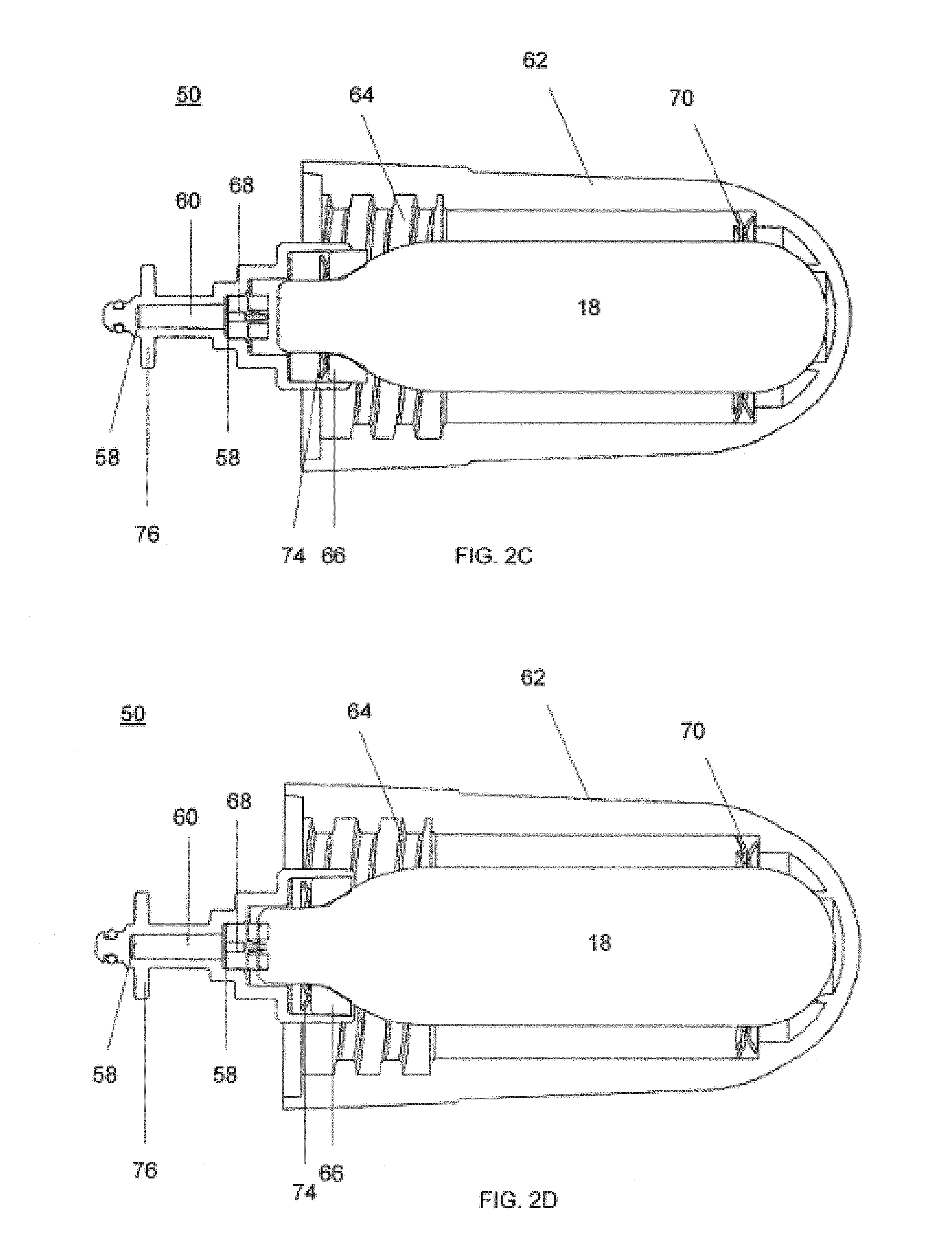
As shown in FIG. 2B and in more detail in FIG. 2C and FIG. 2D, the cartridge 18 can be held by the cartridge receiver 52 such that the cartridge 18 remains intact and unpunctured. In this inactive mode, the cartridge may not be fluidly connected to the valve 32. A removable cartridge cover 62 can be attached to the cartridge receiver 52 such that the inactive mode is maintained while the cartridge is held by the system 10.
In use, the cartridge cover 62 can be removed and supplied with a cartridge containing a cooling fluid. The cartridge cover 62 can then be reattached to the cartridge receiver 52 by turning the cartridge cover 62 until female threads 64 of the cartridge cover 62 engage with male threads of the cartridge receiver 52. The cartridge cover 62 can be turned until resilient force is felt from an elastic seal 66, as shown in FIG. 2C. To place the system 10 into use, the cartridge cover 62 can be further turned until the distal tip of the cartridge 18 is punctured by a puncture pin connector 68, as shown in FIG. 2D. Once the cartridge 18 is punctured, cooling fluid may escape the cartridge by flowing through the filter device 56, where the impurities within the cooling fluid may be captured. The purified cooling fluid then passes to the valve 32, and onto the coolant supply tube 36 to cool the probe 26. In some embodiments the filter device, or portions thereof, may be replaceable.
In some embodiments, the puncture pin connector 68 can have a two-way valve (e.g., ball/seat and spring) that is closed unless connected to the cartridge. Alternately, pressure can be used to open the valve. The valve closes when the cartridge is removed. In some embodiments, there may be a relief valve piloted by a spring which is balanced by high-pressure nitrous when the cartridge is installed and the system is pressurized, but allows the high-pressure cryogen to vent when the cryogen is removed. In addition, the design can include a vent port that vents cold cryogen away from the cartridge port. Cold venting cryogen locally can cause condensation in the form of liquid water to form from the surrounding environment. Liquid water or water vapor entering the system can hamper the cryogenic performance. Further, fluid carrying portions of the cartridge receiver 52 can be treated (e.g., plasma treatment) to become hydrophobic and/or oleophobic so as to repel water or hydrocarbon contaminants.
Turning now to FIG. 3A and FIG. 3B, an exemplary embodiment of probe 300 having multiple needles 302 is described. In FIG. 3A, probe housing 316 includes threads 306 that allow the probe to be threadably engaged with the housing 16 of a cryogenic device. O-rings 308 fluidly seal the probe housing 316 with the device housing 16 and prevent coolant from leaking around the interface between the two components. Probe 300 includes an array of three distally extending needle shafts 302, each having a sharpened, tissue penetrating tip 304. Using three linearly arranged needles allows a greater area of tissue to be treated as compared with a single needle. In use, coolant flows through lumens 310 into the needle shafts 302 thereby cooling the needle shafts 302. Ideally, only the distal portion of the needle shaft 302 would be cooled so that only the target tissue receives the cryogenic treatment. However, as the cooling fluid flows through the probe 300, probe temperature decreases proximally along the length of the needle shafts 302 towards the probe hub 318. The proximal portion of needle shaft 302 and the probe hub 318 contact skin and may become very cold (e.g. -20.degree. C. to -25.degree. C.) and this can damage the skin in the form of blistering or loss of skin pigmentation. Therefore it would be desirable to ensure that the proximal portion of needle shaft 302 and hub 318 remains warmer than the distal portion of needle shaft 302. A proposed solution to this challenge is to include a heater element 314 that can heat the proximal portion of needle shaft 302 and an optional temperature sensor 312 to monitor temperature in this region. To further this, a proximal portion of the needle shaft 302 can be coated with a highly thermally conductive material, e.g., gold, that is conductively coupled to both the needle shaft 302 and heater element 314. Details of this construction are disclosed below.
In the exemplary embodiment of FIG. 3A, resistive heater element 314 is disposed near the needle hub 318 and near a proximal region of needle shaft 302. The resistance of the heater element is preferably 1 .OMEGA. to 1K .OMEGA., and more preferably from 5 .OMEGA. to 50 .OMEGA.. Additionally, a temperature sensor 312 such as a thermistor or thermocouple is also disposed in the same vicinity. Thus, during a treatment as the needles cool down, the heater 314 may be turned on in order to heat the hub 318 and proximal region of needle shaft 302, thereby preventing this portion of the device from cooling down as much as the remainder of the needle shaft 302. The temperature sensor 312 may provide feedback to controller 22 and a feedback loop can be used to control the heater 314. The cooling power of the nitrous oxide may eventually overcome the effects of the heater, therefore the microprocessor may also be programmed with a warning light and/or an automatic shutoff time to stop the cooling treatment before skin damage occurs. An added benefit of using such a heater element is the fact that the heat helps to moderate the flow of cooling fluid into the needle shaft 302 helping to provide more uniform coolant mass flow to the needles shaft 302 with more uniform cooling resulting.
The embodiment of FIG. 3A illustrates a heater fixed to the probe hub. In other embodiments, the heater may float, thereby ensuring proper skin contact and proper heat transfer to the skin. Examples of floating heaters are disclosed in commonly assigned Int'l Pub. No. WO 2010/075448 entitled "Skin Protection for Subdermal Cryogenic Remodeling for Cosmetic and Other Treatments," the entirety of which is incorporated by reference herein.
In this exemplary embodiment, three needles are illustrated. One of skill in the art will appreciate that a single needle may be used, as well as two, four, five, six, or more needles may be used. When a plurality of needles are used, they may be arranged in any number of patterns. For example, a single linear array may be used, or a two dimensional or three dimensional array may be used. Examples of two dimensional arrays include any number of rows and columns of needles (e.g. a rectangular array, a square array, elliptical, circular, triangular, etc.), and examples of three dimensional arrays include those where the needle tips are at different distances from the probe hub, such as in an inverted pyramid shape.
FIG. 3B illustrates a cross-section of the needle shaft 302 of needle probe 300. The needle shaft can be conductively coupled (e.g., welded, conductively bonded, press fit) to a conductive heater 314 to enable heat transfer therebetween. The needle shaft 302 is generally a small (e.g., 20-30 gauge) closed tip hollow needle, which can be between about 0.2 mm and 15 cm, preferably having a length from about 0.3 cm to about 1.5 cm. The conductive heater element 314 can be housed within a conductive block 315 of high thermally conductive material, such as aluminum and include an electrically insulated coating, such as Type III anodized coating to electrically insulate it without diminishing its heat transfer properties. The conductive block 315 can be heated by a resister or other heating element (e.g. cartridge heater, nichrome wire, etc.) bonded thereto with a heat conductive adhesive, such as epoxy. A thermistor can be coupled to the conductive block 315 with heat conductive epoxy allows temperature monitoring. Other temperature sensors may also be used, such as a thermocouple.
A cladding 320 of conductive material is directly conductively coupled to the proximal portion of the shaft of the needle 302, which can be stainless steel. In some embodiments, the cladding 320 is a layer of gold, or alloys thereof, coated on the exterior of the proximal portion of the needle shaft 302. In some embodiments, the exposed length of cladding 320 on the proximal portion of the needle is 2-100 mm. In some embodiments, the cladding 320 can be of a thickness such that the clad portion has a diameter ranging from 0.017-0.020 in., and in some embodiments 0.0182 in. Accordingly, the cladding 320 can be conductively coupled to the material of the needle 302, which can be less conductive, than the cladding 320. The cladding 320 may modify the lateral force required to deflect or bend the needle 26. Cladding 320 may be used to provide a stiffer needle shaft along the proximal end in order to more easily transfer force to the leading tip during placement and allow the distal portion of the needle to deflect more easily when it is dissecting a tissue interface within the body. The stiffness of needle 26 can vary from one end to the other end by other means such as material selection, metal tempering, variation of the inner diameter of the needle 26, or segments of needle shaft joined together end-to-end to form one contiguous needle 26. In some embodiments, increasing the stiffness of the distal portion of the needle 26 can be used to flex the proximal portion of the needle to access difficult treatment sites as in the case of upper limb spasticity where bending of the needle outside the body may be used to access a target peripheral nerve along the desired tissue plane.
In some embodiments, the cladding 320 can include sub-coatings (e.g., nickel) that promote adhesion of an outer coating that would otherwise not bond well to the needle shaft 302. Other highly conductive materials can be used as well, such as copper, silver, aluminum, and alloys thereof. In some embodiments, a protective polymer or metal coating can cover the cladding to promote biocompatibility of an otherwise non-biocompatible but highly conductive cladding material. Such a biocompatible coating however, would be applied to not disrupt conductivity between the conductive block 315. In some embodiments, an insulating layer, such as a ceramic material, is coated over the cladding 320, which remains conductively coupled to the needle shaft 302.
In use, the cladding 320 can transfer heat to the proximal portion of the needle 302 to prevent directly surrounding tissue from dropping to cryogenic temperatures. Protection can be derived from heating the non-targeting tissue during a cooling procedure, and in some embodiments before the procedure as well. The mechanism of protection may be providing heat to pressurized cryogenic cooling fluid passing within the proximal portion of the needle to affect complete vaporization of the fluid. Thus, the non-target tissue in contact with the proximal portion of the needle shaft 302 does not need to supply heat, as opposed to target tissue in contact with the distal region of the needle shaft 302. To help further this effect, in some embodiments the cladding 320 is coating within the interior of the distal portion of the needle, with or without an exterior cladding. To additionally help further this effect, in some embodiments, the distal portion of the needle can be thermally isolated from the proximal portion by a junction, such as a ceramic junction. While in some further embodiments, the entirety of the proximal portion is constructed from a more conductive material than the distal portion.
In use, it has been determined experimentally that the cladding 320 can help limit formation of a cooling zone to the distal portion of the needle shaft 302, which tends to demarcate at a distal end of the cladding 320. Accordingly, cooling zones are formed only about the distal portions of the needles. Thus, non-target tissue in direct contact with proximal needle shafts remain protected from effects of cryogenic temperatures. Such effects can include discoloration and blistering of the skin. Such cooling zones may be associated with a particular physical reaction, such as the formation of an ice-ball, or with a particular temperature required to therapeutically affect the tissue therein.
Standard stainless steel needles and gold clad steel needles were tested in porcine muscle and fat. Temperatures were recorded measured 2 mm from the proximal end of the needle shaft, about where the cladding distally terminates, and at the distal tip of the needles. As shown, temperatures for clad needles were dramatically warmer at the 2 mm point versus the unclad needles, and did not drop below 4.degree. C. The 2 mm points of the standard needles however almost equalize in temperature with the distal tip.
FIGS. 3C and 3D illustrates a detachable probe tip 322 having a hub connector 324 and an elongated probe 326. The probe tip 322 shares much of its construction with probe 300. However, the elongated probe 326 features a blunt tip 328 that is adapted for blunt dissection of tissue. The blunt tip 328 can feature a full radius tip, less than a full radius tip, or conical tip. In some embodiments, a dulled or truncated needle is used. The elongated probe 326 can be greater than 20 gauge in size, and in some embodiments range in size from 25-30 gauge. As with the embodiments described above, an internal supply tube 330 extends in cantilever. However, the exit of the supply tube 330 can be disposed at positions within the elongated probe 326 other than proximate the blunt tip 328. Further, the supply tube 330 can be adapted to create an elongated zone of cooling, e.g., by having multiple exit points for cryofluid to exit from.
The elongated probe 326 and supply tube 330 may be configured to resiliently bend in use, throughout their length at angles approaching 120.degree., with a 5-10 mm bend radius. This may be very challenging considering the small sizes of the elongated probe 326 and supply tube 330, and also considering that the supply tube 330 is often constructed from fused silica. Accordingly, the elongated probe 326 can be constructed from a resilient material, such as stainless steel, and of a particular diameter and wall thickness [0.004 to 1.0 mm], such that the elongated probe in combination with the supply tube 330 is not overly resilient so as to overtly resist manipulation, but sufficiently strong so as to prevent kinking that can result in coolant escaping. For example, the elongated probe can be 15 gauge or smaller in diameter, even ranging from 20-30 gauge in diameter. The elongated probe can have a very disparate length to diameter ratio, for example, the elongated probe can be greater than 30 mm in length, and in some cases range from 30-100 mm in length. To further the aforementioned goals, the supply tube 330 can include a polymer coating 332, such as a polyimide coating that terminates approximately halfway down its length, to resist kinking and aid in resiliency. The polymer coating 332 can be a secondary coating over a primary polyimide coating that extends fully along the supply tube. However, it should be understood that the coating is not limited to polyimide, and other suitable materials can be used. In some embodiments, the flexibility of the elongated probe 326 will vary from the proximal end to the distal end. For example, by creating certain portions that have more or less flexibility than others. This may be done, for example, by modifying wall thickness, adding material (such as the cladding discussed above), and/or heat treating certain portions of the elongated probe 326 and/or supply tube 330. For example, decreasing the flexibility of elongated probe 326 along the proximal end can improve the transfer of force from the hand piece to the elongated probe end for better feel and easier tip placement for treatment. The elongated probe and supply line 330 are may be configured to resiliently bend in use to different degrees along the length at angles approaching 120.degree., with a varying bend radius as small as 5 mm. In some embodiments, the elongated probe 326 will have external markings along the needle shaft indicating the length of needle inserted into the tissue.
FIG. 3E illustrates an exemplary detachable probe tip 322 inserted through skin surface SS. As illustrated, the probe tip 322 is inserted along an insertion axis IA through the skin surface SS. Thereafter, the needle may be bent away from the insertion axis IA and advanced toward a target tissue TT in order to position blunt tip 328 adjacent to the target tissue TT. In some embodiments, the target tissue may be the infrapatellar branch of the saphenous nerve. In other embodiments the target tissue may be one or more branches of the anterior femoral cutaneous nerve or the lateral femoral cutaneous nerve.
In some embodiments, the probe tip 322 does not include a heating element, such as the heater described with reference to probe 300, since the effective treating portion of the elongated probe 326 (i.e., the area of the elongated probe where a cooling zone emanates from) is well laterally displaced from the hub connector 324 and elongated probe proximal junction. Embodiments of the supply tube are further described below and within commonly assigned U.S. Pub. No. 2012/0089211, which is incorporated by reference.
FIGS. 4A-4C illustrate an exemplary method of creating a hole through the skin that allows multiple insertions and positioning of a cryoprobe therethrough. In FIG. 4A a cannula or sheath 1902 is disposed over a needle 1904 having a tissue penetrating distal end 1908. The cannula may have a tapered distal portion 1906 to help spread and dilate the skin during insertion. The needle/sheath assembly is then advanced into and pierces the skin 1910 into the desired target tissue 1912. The inner pathway of the cannula or sheath 1902 may be curved to assist in directing the flexible needle 1904, or other probe, into a desired tissue layer coincident with the desired needle path in the tissue. Once the needle/sheath assembly has been advanced to a desired location, the needle 1904 may be proximally retracted and removed from the sheath 1902. The sheath now may be used as an easy way of introducing a cryoprobe through the skin without piercing it, and directing the cryoprobe to the desired target treatment area. FIG. 4B shows the sheath 1902 in position with the needle 1904 removed. FIG. 4C shows insertion of a cryoprobe 1914 into the sheath such that a blunt tip 1916 of the cryoprobe 1914 is adjacent the target treatment tissue. The cryoprobe may then be cooled and the treatment tissue cooled to achieve any of the cosmetic or therapeutic effects discussed above. In this embodiment, the cryoprobe preferably has a blunt tip 1916 in order to minimize tissue trauma. In other embodiments, the tip may be sharp and be adapted to penetrate tissue, or it may be round and spherical. The cryoprobe 1914 may then be at least partially retracted from the sheath 1902 and/or rotated and then re-advanced to the same or different depth and repositioned in sheath 1902 so that the tip engages a different portion of the target treatment tissue without requiring an additional piercing of the skin. The probe angle relative to the tissue may also be adjusted, and the cryoprobe may be advanced and retracted multiple times through the sheath so that the entire target tissue is cryogenically treated.
While the embodiment of FIGS. 4A-4C illustrates a cryoprobe having only a single probe, the cryoprobe may have an array of probes. Any of the cryoprobes described above may be used with an appropriately sized sheath. In some embodiments, the cryoprobe comprises a linear or two dimensional array of probes. Lidocaine or other local anesthetics may be used during insertion of the sheath or cryoprobe in order to minimize patient discomfort. The angle of insertion for the sheath may be anywhere from 0 to 180 degrees relative to the skin surface, and in specific embodiments is 15 to 45 degrees. The sheath may be inserted at any depth, but in specific embodiments of treating lines/wrinkles of the face, the sheath may be inserted to a depth of 1 mm to 10 mm, and more preferably to a depth of 2 mm to 5 mm.
In an alternative embodiment seen in FIG. 4D, the sheath 1902 may include an annular flange 1902b on an outside surface of the sheath in order to serve as a stop so that the sheath is only inserted a preset amount into the tissue. The position of the flange 1902b may be adjustable or fixed. The proximal end of the sheath in this embodiment, or any of the other sheath embodiments may also include a one way valve such as a hemostasis valve to prevent backflow of blood or other fluids that may exit the sheath. The sheath may also insulate a portion of the cryoprobe and prevent or minimize cooling of unwanted regions of tissue.
Any of the cryoprobes described above may be used with the sheath embodiment described above (e.g. in FIGS. 3B, 4A-4C). Other cryoprobes may also be used with this sheath embodiment, or they may be used alone, in multi-probe arrays, or combined with other treatments. For example, a portion of the cryoprobe 2006 may be insulated as seen in FIG. 5. Cryoprobe 2006 includes a blunt tip 2004 with an insulated section 2008 of the probe. Thus, when the cryoprobe is disposed in the treatment tissue under the skin 2002 and cooled, the cryoprobe preferentially creates a cooling zone along one side while the other side remains uncooled, or only experiences limited cooling. For example, in FIG. 5, the cooling zone 2010 is limited to a region below the cryoprobe 2006, while the region above the cryoprobe and below the skin 2002 remain unaffected by the cooling.
Different zones of cryotherapy may also be created by different geometries of the coolant fluid supply tube that is disposed in the cryoprobe. FIGS. 6-9 illustrate exemplary embodiments of different coolant fluid supply tubes. In FIG. 6 the coolant fluid supply tube 2106 is offset from the central axis of a cryoprobe 2102 having a blunt tip 2104. Additionally, the coolant fluid supply tube 2106 includes several exit ports for the coolant including circular ports 2110, 2112 near the distal end of the coolant fluid supply tube and an elliptical port 2108 proximal of the other ports. These ports may be arranged in varying sizes, and varying geometries in order to control the flow of cryofluid which in turn controls probe cooling of the target tissue. FIG. 7 illustrates an alternative embodiment of a coolant fluid supply tube 2202 having a plurality of circular ports 2204 for controlling cryofluid flow. FIG. 8 illustrates yet another embodiment of a coolant fluid supply tube 2302 having a plurality of elliptical holes 2304, and FIG. 9 shows still another embodiment of a coolant fluid supply tube 2402 having a plurality of ports ranging from smaller diameter circular holes 2404 near the distal end of the supply tube 2402 to larger diameter circular holes 2406 that are more proximally located on the supply tube 2402.
As discussed above, it may be preferable to have a blunt tip on the distal end of the cryoprobe in order to minimize tissue trauma. The blunt tip may be formed by rounding off the distal end of the probe, or a bladder or balloon 2506 may be placed on the distal portion of the probe 2504 as seen in FIG. 10. A filling tube or inflation lumen 2502 may be integral with or separate from the cryoprobe 2504, and may be used to deliver fluid to the balloon to fill the balloon 2506 up to form the atraumatic tip.
In some instances, it may be desirable to provide expandable cryoprobes that can treat different target tissues or accommodate different anatomies. For example, in FIGS. 11 and 12, a pair of cryoprobes 2606 with blunt tips 2604 may be delivered in parallel with one another and in a low profile through a sheath 2602 to the treatment area. Once delivered, the probes may be actuated to separate the tips 2604 from one another, thereby increasing the cooling zone. After the cryotherapy has been administered, the probes may be collapsed back into their low profile configuration, and retracted from the sheath.
In some embodiments, the probe may have a sharp tissue piercing distal tip, and in other embodiments, the probe may have a blunt tip for minimizing tissue trauma. To navigate through tissue, it may be desirable to have a certain column strength for the probe in order to avoid bending, buckling or splaying, especially when the probe comprises two or more probes in an array. One exemplary embodiment may utilize a variable stiff portion of a sleeve along the probe body to provide additional column strength for pushing the probe through tissue.
An exemplary algorithm 400 for controlling the heater element 314, and thus for transferring heat to the cladding 320, is illustrated in FIG. 13. In FIG. 13, the start of the interrupt service routine (ISR) 402 begins with reading the current needle hub temperature 404 using a temperature sensor such as a thermistor or thermocouple disposed near the needle hub. The time of the measurement is also recorded. This data is fed back to controller 22 where the slope of a line connecting two points is calculated. The first point in the line is defined by the current needle hub temperature and time of its measurement and the second point consists of a previous needle hub temperature measurement and its time of measurement. Once the slope of the needle hub temperature curve has been calculated 406, it is also stored 408 along with the time and temperature data. The needle hub temperature slope is then compared with a slope threshold value 410. If the needle hub temperature slope is less than the threshold value then a treating flag is activated 412 and the treatment start time is noted and stored 414. If the needle hub slope is greater than or equal to the slope threshold value 410, an optional secondary check 416 may be used to verify that cooling has not been initiated. In step 416, absolute needle hub temperature is compared to a temperature threshold. If the hub temperature is less than the temperature threshold, then the treating flag is activated 412 and the treatment start time is recorded 414 as previously described. As an alternative, the shape of the slope could be compared to a norm, and an error flag could be activated for an out of norm condition. Such a condition could indicate the system was not heating or cooling sufficiently. The error flag could trigger an automatic stop to the treatment with an error indicator light. Identifying the potential error condition and possibly stopping the treatment may prevent damage to the proximal tissue in the form of too much heat, or too much cooling to the tissue. The algorithm preferably uses the slope comparison as the trigger to activate the treatment flag because it is more sensitive to cooling conditions when the cryogenic device is being used rather than simply measuring absolute temperature. For example, a needle probe exposed to a cold environment would gradually cool the needle down and this could trigger the heater to turn on even though no cryogenic cooling treatment was being conducted. The slope more accurately captures rapid decreases in needle temperature as are typically seen during cryogenic treatments.
When the treatment flag is activated 418 the needle heater is enabled 420 and heater power may be adjusted based on the elapsed treatment time and current needle hub temperature 422. Thus, if more heat is required, power is increased and if less heat is required, power is decreased. Whether the treatment flag is activated or not, as an additional safety mechanism, treatment duration may be used to control the heater element 424. As mentioned above, eventually, cryogenic cooling of the needle will overcome the effects of the heater element. In that case, it would be desirable to discontinue the cooling treatment so that the proximal region of the probe does not become too cold and cause skin damage. Therefore, treatment duration is compared to a duration threshold value in step 424. If treatment duration exceeds the duration threshold then the treatment flag is cleared or deactivated 426 and the needle heater is deactivated 428. If the duration has not exceeded the duration threshold 424 then the interrupt service routine ends 430. The algorithm then begins again from the start step 402. This process continues as long as the cryogenic device is turned on.
Preferred ranges for the slope threshold value may range from about -5.degree. C. per second to about -90.degree. C. per second and more preferably range from about -30.degree. C. per second to about -57.degree. C. per second. Preferred ranges for the temperature threshold value may range from about 15.degree. C. to about 0.degree. C., and more preferably may range from about 0.degree. C. to about 10.degree. C. Treatment duration threshold may range from about 15 seconds to about 75 seconds.
It should be appreciated that the specific steps illustrated in FIG. 13 provide a particular method of heating a cryogenic probe, according to an embodiment of the present invention. Other sequences of steps may also be performed according to alternative embodiments. For example, alternative embodiments of the present invention may perform the steps outlined above in a different order. Moreover, the individual steps illustrated in FIG. 13 may include multiple sub-steps that may be performed in various sequences as appropriate to the individual step. Furthermore, additional steps may be added or removed depending on the particular applications.
The heating algorithm may be combined with a method for treating a patient. Referring now to FIG. 14, a method 100 facilitates treating a patient using a cryogenic cooling system having a reusable or disposable handpiece either of which that can be self-contained or externally powered with replaceable needles such as those of FIG. 1B and a limited capacity battery or metered electrical supply. Method 100 generally begins with a determination 110 of the desired tissue therapy and results, such as the inhibition of pain from a particular site. Appropriate target tissues for treatment are identified 112 (a tissue that transmits the pain signal), allowing a target treatment depth, target treatment temperature profile, or the like to be determined. Step 112 may include performing a tissue characterization and/or device diagnostic algorithm, based on power draw of system 10, for example.
The application of the treatment algorithm 114 may include the control of multiple parameters such as temperature, time, cycling, pulsing, and ramp rates for cooling or thawing of treatment areas. In parallel with the treatment algorithm 114, one or more power monitoring algorithms 115 can be implemented. An appropriate needle assembly can then be mounted 116 to the handpiece, with the needle assembly optionally having a needle length, skin surface cooling chamber, needle array, and/or other components suitable for treatment of the target tissues. Simpler systems may include only a single needle type, and/or a first needle assembly mounted to the handpiece.
Pressure, heating, cooling, or combinations thereof may be applied 118 to the skin surface adjacent the needle insertion site before, during, and/or after insertion 120 and cryogenic cooling 122 of the needle and associated target tissue. Non-target tissue directly above the target tissue can be protected by directly conducting energy in the form of heat to the cladding on a proximal portion of the needle shaft during cooling. Upon completion of the cryogenic cooling cycle the needles will need additional "thaw" time 123 to thaw from the internally created cooling zone to allow for safe removal of the probe without physical disruption of the target tissues, which may include, but not be limited to nerves, muscles, blood vessels, or connective tissues. This thaw time can either be timed with the refrigerant valve shut-off for as short a time as possible, preferably under 15 seconds, more preferably under 5 seconds, manually or programmed into the controller to automatically shut-off the valve and then pause for a chosen time interval until there is an audible or visual notification of treatment completion.
Heating of the needle may be used to prevent unwanted skin damage using the apparatus and methods previously described. The needle can then be retracted 124 from the target tissue. If the treatment is not complete 126 and the needle is not yet dull 128, pressure and/or cooling can be applied to the next needle insertion location site 118, and the additional target tissue treated. However, as small gauge needles may dull after being inserted only a few times into the skin, any needles that are dulled (or otherwise determined to be sufficiently used to warrant replacement, regardless of whether it is after a single insertion, 5 insertions, or the like) during the treatment may be replaced with a new needle 116 before the next application of pressure/cooling 118, needle insertion 120, and/or the like. Once the target tissues have been completely treated, or once the cooling supply canister included in the self-contained handpiece is depleted, the used canister and/or needles can be disposed of 130. The handpiece may optionally be discarded.
As noted above, suitable target tissues can be selected that include a particular sensory nerve associated with pain, for example, such as: Myofascial, Fibromylagia, Lateral and Medial epicondylitis, Llio-hypo/llio-inguinal, Pudendal, Pyriformis, Osteo-Arthritis of the Knee, Patellar Tendonitis, Diabetic neuropathies, Carpal Tunnel, Phantom Limb, Migraine, Trigeminal Neuralgia, Occipital Neuralgia, Shoulder Arthritis, Shoulder Tendonitis, Suprascapular, Failed Back, Sciatica, Facet, Herniated Disc, Sacoiliac, Sciatic, Morton's Neuroma, and Plantar Fasciitis pain.
With respect to knee pain, the infrapatellar branch of the saphenous nerve (ISN), illustrated in FIG. 15, may be targeted for treatment according to embodiments of the present invention. In some embodiments of the invention, osteoarthritis of the knee or other painful conditions causing pain in the inferior aspect of the anterior knee may be treated by targeting the infrapatella branch with cooling treatment. Alternatively, or in addition thereto, the anterior femoral cutaneous nerve and/or the lateral femoral cutaneous nerve may be treated to reduce the knee pain experienced by a patient. The saphenous nerve arises as a division of the femoral nerve and leaves the adductor canal between the tendons of gracilis and semitendinosus. It then divides into the main saphenous branch, which continues down to the ankle, and the ISN. The ISN traverses the knee below the patella, dividing into three branches before combining with the anterior branch of the lateral cutaneous nerve of the thigh, the intermediate cutaneous nerves of the thigh and the anterior branch of the medial cutaneous nerve of the thigh to form the prepatella plexus.
FIG. 16 depicts the interconnections of the saphenous nerve. The saphenous nerve, located about the middle of the thigh, gives off a branch--the ISN--which joins the subsartorial plexus. The ISN pierces the sartorius muscle and fascia lata, and is distributed to the skin in front of the patella. The ISN communicates above the knee with the anterior cutaneous branches of the femoral nerve; below the knee with other branches of the saphenous nerve; and, on the lateral side of the knee, with branches of the lateral femoral cutaneous nerve, forming the plexus patellae. The ISN supplies sensation to the area surrounding and anterior to the knee. Thus, in some embodiments of the present invention, cooling treatments may be provided with the devices and methods disclosed herein to reduce pain sensation in the area of the knee. The anterior femoral cutaneous nerve and the lateral femoral cutaneous nerve may also supply sensation to the area surrounding the knee and may also be treated in some embodiments. In exemplary embodiments, cooling treatments are provided which reduce the pain experienced by osteo-arthritis patients.
FIG. 17 shows an anatomical illustration of the medial aspect of the knee. The figure illustrates the saphenous nerve giving rise to its infrapatella branch in the subartorial canal. The ISN is shown as it pierces the distal sartorius muscle (S) and fascia lata to become subcutaneous. The ISN superficially presents an arc-like course between the apex of the patella cranially and tibial tubercle caudally, and ends in the form of two superior and inferior terminal branches.
FIG. 18 shows a medial view of the position and division of the ISN. As shown in the medial view of the ISN, the ISN emerges through the fascia lata medial generally at a level with the inferior pole of the patella. Due to patient to patient variation with regards to both nerve location and nerve branching, the ISN branch may occur generally between 46 and 64 mm from, and may occur on average 55 mm from, the medial border of the patella, and may occur generally between 36 and 55 mm from, and may occur on average 44 mm from, the medial border of the patellar tendon. The ISN may then divide into three branches medial to the inferior pole of the patella, anterior to the long saphenous vein. These branches of the ISN are called, the superior branch, the middle branch, and the inferior branch. The Superior Branch runs transversely just inferior to the inferior pole of the patella, ending lateral to the patellar tendon. The Middle Branch divides from the Superior Branch medial to the medial border of the patellar tendon and runs obliquely across the tendon, dividing into its terminal branches at the lateral border. The Inferior Branch is the smallest and runs down in relation to the medial border of the tendon, ending at the level of the tibial tuberosity.
Thus in some embodiments, the ISN may be located relative to key anatomical landmarks. For example, FIG. 19 illustrates exemplary anatomical landmarks for approximating the location of the ISN. In some methods, the ISN may be located or approximated as about 55 mm posterior to the lower pole of the patella. In some methods, the ISN may be located or approximated as about 44 mm posterior to the medial border of the patellar tendon. In some embodiments, the ISN may be located or approximated as about 55 mm from the lower pole of the patella and about 44 mm from the medial border of the patellar tendon. In some embodiments, the ISN position may be approximated based on a location of the great saphenous vein. FIG. 19 also illustrates a treatment area where cooling may be applied to approximate the location of the ISN.
An example treatment zone is shown in FIG. 20. Here, a treatment zone is shown for treating an infrapatellar branch of a saphenous nerve. The treatment zone is shown as an area defined by four borders. A first boundary (uppermost/superior boundary) of the treatment zone may be defined by the approximate mid-line of the patella. The second boundary (the lateral boundary) of the treatment zone may be defined as about 55-65 mm lateral from the lower pole of the patella. A third boundary (the medial boundary) of the treatment zone may be defined as about 44 mm laterally from the medial aspect of the patellar tendon. A fourth boundary (bottommost/inferior boundary) for the treatment zone may be defined by a line parallel to the first boundary which intersects the tibial tubercule. In some embodiments, the uppermost/superior boundary may be defined by the superior pole of the patella. Optionally, the lateral boundary may be defined as about 65 mm from the center of the patella.
The shown treatment zone can be used to treat the infrapatellar branch of a saphenous nerve with high likelihood of success. In one study, which is discussed below, and shown in FIG. 20, a series of treatments were performed along the second boundary between the first and fourth boundaries and was successful in placing a needle of a cryogenic device into good proximity with the infrapatellar branch, to successfully remodel the infrapatellar branch with a cooling zone generated by the needle. In some cases, treatments can be performed along the third boundary to attain an even higher likelihood of success. The treatments are performed such that each generated cooling zone is directly adjacent, or overlapping with a previously created or concurrently created cooling zone. In some cases, a device, such as the one shown in FIG. 3A, having a plurality of needles is used to treat along the second and/or third boundary. For the sake of redundancy, the treatment zones can overlap, for example, by placing one needle of the plurality of needles in a previously created needle hole, thus linking each treatment. In some embodiments of the invention, a treatment guide or template may be fashioned for facilitating the identification of the infrapatellar branch.
FIG. 21A and FIG. 21B illustrate exemplary guides or templates 500, 501 which may be used to approximate a treatment zone. FIG. 21A illustrates an exemplary guide 500 which may be substantially planar and include a first corner 502, a second corner 504, and a third corner 506. The first corner 502 may be aligned with the lower pole of the patella. The second corner 504 may be aligned with the medial aspect of the patellar tendon. The third corner may then approximate the location of the infrapatellar branch. The third corner 506 may be separated by a first distance 508 from the first corner 502. The first distance 508 may be between 30 and 70 mm. The third corner 506 may also be separated by a second distance 510 from the second corner 504. The second distance 510 may be between 25 and 60 mm. The template 500 may be constructed from thin flexible plastic sheet, and may in some embodiments be transparent. In some embodiments, template 500 includes an adhesive backing for temporarily adhering the template 500 to a skin surface. In some embodiments, the template may contain a transdermal medication, such as anti-inflammatory and anesthesia (e.g., lidocaine) drugs. An example of such construction is shown in U.S. Publication No. 2010/0234471, which discloses lidocain tape and is incorporated herein by reference.
FIG. 21B illustrates another embodiment 501 of a treatment guide or template which may be used for approximating a treatment zone for treating the infrapatellar branch of a patient. The guide 501 includes a window 512 that defines a treatment zone. Guide 501 may also include a first indicia 514 and a second indicia 516. Indicia 514 may be aligned with the midline of the patella for example. Indicia 516 may be aligned with the tibial tubercle. The medial edge of window 512 may be at a first distance D1 and the lateral edge of window 512 may be at a second distance D2. The first distance D1 may be between 30 and 70 mm. The second distance D2 may be between 25 and 60 mm.
A study was performed on 21 human patients for treatment of osteoarthritis of the knee, or symptoms resembling OA, using some embodiments of the present invention. Out of the 21 patients, 7 (33%) had one knee treated and 14 (65%) had bilateral treatments. In total, 35 knees were treated. The average age of the patients was 55 years with an age range between 30-81 years with a standard deviation of 11.01. The Western Ontario and McMaster University Arthritis Index (WOMAC) provided a validated scale for measuring the impact of arthritis on patients when performing daily activities. WOMAC of each patient was assessed at baseline and 7 days post-treatment. Further, a Visual Analog Scale of Pain (VAS) provided a measure of overall patient pain levels using visual facial expressions. VAS of each patient was assessed at baseline, pre-treatment, post treatment, and at 7 days and 30 days post-treatment.
The primary endpoint of the study was to provide a significant reduction of pain using validated pain scales. It was found that the patients on average received 70-80% post-procedure improvement using these scales. A device similar to the one shown in FIG. 3A was used, i.e., a device having 3 cryogenic needles, with each being approximately 6 mm long. Each needle included a conductive coating, coupled to a heater as described with respect to FIG. 3B, that extended approximately 2 mm down the needle. Treatments times were 60 seconds long each. Typically between four and ten treatments were performed on each knee. The treatments were performed using the treatment zone shown in FIG. 20 along the second boundary. Treatments typically started at the first boundary and ended at the fourth boundary but sometimes started at the fourth boundary and ended at the first boundary. In this manner a continuous treatment fence was created. In some cases, particularly if the patient still exhibited pain or other sensations associated with osteoarthritis, a second set of treatments also extended across the first boundary. In some cases the starting point along the second boundary was identified using PENS. In some cases the treatment continued along the treatment line until the patient detected a cessation or diminished pain. Cooling zones were made to overlap to increase the likelihood that the infrapatellar branch of the saphenous nerve was affected, such that second degree nerve injury occurred to instigate Wallerian degeneration.
The results of this study were surprising and unexpected, as experts in the field provided professional opinions that the procedure would provide no pain relief. Accordingly, there was no expectation for the level of success demonstrated in the study. The results of the study are summarized in FIG. 22-FIG. 25.
FIG. 22 summarizes the WOMAC score improvement of the 35 knees from 21 subjects 7 days after treatment. Scores from assessments were made using WOMAC Osteoarthritis Index NSR3.1. Pain, stiffness and function subscale scores were calculated by adding the scores within each dimension, according to WOMAC User Guide X. FIG. 22 shows that WOMAC Pain scores improved 71% from before the procedure to the 7 day follow-up visit. Further, WOMAC Stiffness scores improved 69% and WOMAC Function scores improved 71% when assessed 7 days after treatment. FIG. 23 shows the number of subjects reporting improvement in WOMAC Pain score at 7 days after treatment. As shown, approximately 80% of the subjects reported a 60%-100% improvement in WOMAC Pain Score 7 days after treatment. It was determined that one patient, who reported no improvement after 7 days, was treated in an incorrect position therefore adjusting the position of the nerve and the anatomy underlying the skin.
FIG. 24 summarizes the improvement in patient VAS scores following treatment. VAS scores decreased for all subjects following treatment. On average the VAS score plot shows an 80% improvement from baseline immediately post procedure, then 64% improvement at 7 days, and 62% at 30 days. FIG. 25 summarizes the duration of benefit from the cooling treatment. As can be seen, 80% of subjects reported pain relief from the treatment 56 days after treatment. The duration of the treatment is consistent with the rate of distal re-innervation of approximately 0.8-1 mm per day. Accordingly, it may be possible to provide sustained benefit with 4-6 treatments per year. FIG. 26 summarizes the percent of knees reporting anticipated observations at 7 days, 30 days, and 56 days post-treatment. A device using a skin warmer, such as the device depicted in FIG. 2A or FIG. 3A-3B, may protect the collateral tissue during treatment of the nerve and thereby reduce the occurrence of erosion, crusting, dimpling, hyperpigmentation, and hypopigmentation. The cladding shown in FIG. 3B may also be used in some embodiments to reduce the occurrence of erosion, crusting, dimpling, hyperpigmentation, and hypopigmentation. FIGS. 27A and 27B summarize the patient's subjective satisfaction with the cooling treatment. When asked whether they would recommend the treatment to a family member, 95% of patients responded affirmatively 7 days after treatment, 94% responded affirmatively 30 days after treatment, and 88% responded affirmatively 56 days after treatment. When asked whether they would have the treatment again, 86% responded affirmatively 7 days after treatment, 94% responded affirmatively 30 days after treatment, and 88% responded affirmatively 56 days after treatment. Thus temporary pain relief may be provided to patients suffering from osteoarthritis as indicated by the VAS measurements. Further, such treatments may provide an improved quality of life as indicated by the WOMAC measurements. Such treatments may also reduce the amount of drug therapy required, postpone invasive surgeries, and may provide an opportunity for physical rehabilitation (e.g., strength, flexibility, etc.). Furthermore the procedure may be used either pre- or post-operatively. Before total knee replacement surgery, the procedure may be used to limit pain, allow patients to strengthen the joint which may improve surgical outcomes. Post surgically, the procedure may be used to limit the use of opioids or other pain killers and or allow the patient to reduce residual post-surgical pain.
Although the above described procedures treated the infrapatellar branch of the saphenous nerve using cold to reduce pain and other symptoms associated with osteo-arthritis, other methods and devices could be used to temporarily or permanently disable the ISN. Examples include thermal nerve ablation such as with RF energy, or neurolysis using injections of phenol or ethyl alcohol.
In some embodiments of the present invention, treatment guidance can rely on rigid or boney landmarks because they are less dependent upon natural variations in body size or type, e.g. BMI. Soft tissues, vasculature and peripheral nerves pass adjacent to the rigid landmarks because they require protection and support. By positioning the patient's skeletal structure in a predetermined position (e.g. knee bent 30 degrees or fully extended), one can reliably position the bones, ligaments, cartilage, muscle, soft tissues (including fascia), vasculature, and peripheral nerves. External palpation can then be used to locate the skeletal structure and thereby locate the pathway and relative depth of a peripheral nerve targeted for treatment.
A treatment of peripheral nerve tissue to at least -20.degree. C. is sufficient to trigger 2nd degree Wallerian degeneration of the axon and mylinated sheath. Conduction along the nerve fibers is stopped immediately following treatment. This provides immediate feedback as to the location of the target peripheral nerve or associated branches when the associated motion or sensation is modified. This can be used to refine rigid landmark guidance of future treatments or to determine whether addition treatment is warranted.
Without reliable rigid landmarks, however, the treatment may rely on creating a block or treatment zone as depicted in FIG. 19 and FIG. 20. Alternatively, by using rigid landmarks, one may be able to direct the treatment pattern to specific anatomical sites where the peripheral nerve is located with the highest likelihood. Feedback from the patient immediately after each treatment may verify the location of the target peripheral nerve and its associated branches. Thus, it should be understood that in some embodiments, the use of an electronic nerve stimulation device to discover nerve location is not needed or used, since well-developed treatment zones can locate target nerves. This may be advantageous, due the cost and complexity of electronic nerve stimulation devices, which are also not always readily available.
In alternative embodiments of the invention, one could use an electronic nerve stimulation device (either transcutaneous or percutaneous) to stimulate the target peripheral nerve and its branches. With transcutaneous electric nerve stimulation (TENS) the pathway of the nerve branch can be mapped in an X-Y coordinates coincident with the skin surface. The Z coordinate corresponding to depth normal to the skin surface can be inferred by the sensitivity setting of the electrical stimulation unit. For example, a setting of 3.25 mA and pulse duration of 0.1 ms may reliably stimulate the frontal branch of the temporal nerve when it is within 7 mm of the skin surface. If a higher current setting or longer pulse duration is required to stimulate the nerve, then the depth may be >7 mm. A percutaneous electrical nerve stimulator (PENS) can also be used to locate a target peripheral nerve. Based on rigid anatomical landmarks, a PENS needle can be introduced through the dermis and advanced into the soft tissues. Periodic stimulating pulses at a rate of 1-3 Hz may be used to stimulate nerves within a known distance from the PENS needle. When the target nerve is stimulated, the sensitivity of the PENS can be reduced (e.g. lowering the current setting or pulse duration) narrowing the range of stimulation. When the nerve is stimulated again, now within a smaller distance, the PENS sensitivity can be reduced further until the nerve stimulation distance is within the therapy zone dimensions. At this point, the PENS needle can be replaced with the focused cold therapy needle(s) and a treatment can be delivered. The PENS and focused cold therapy needles can be introduced by themselves or through a second larger gage needle or cannula. This may provide a rigid and reproducible path when introducing a needle and when replacing one needle instrument with another. A rigid pathway may guide the needle to the same location by preventing needle tip deflection, which could lead to a misplaced therapy and lack of efficacy.
While many of the examples disclosed herein related to puncturing the skin in a transverse manner to arrive at a target sensory nerve, other techniques can be used to guide a device to a target sensory nerve. For example, insertion of devices can be made parallel to the surface of the skin, such that the (blunted) tip of the device glides along a particular fascia to arrive at a target sensory nerve. Such techniques and devices are disclosed in U.S. Pub. No. 2012/0089211, the entirety of which is incorporated by reference. Possible advantages may include a single insertion site, and guidance of a blunt tip along a layer common with the path or depth of the target infrapatellar saphenous nerve. This technique may be a position-treatment--thaw, reposition treatment, thaw, etc.
While the exemplary embodiments have been described in some detail for clarity of understanding and by way of example, a number of modifications, changes, and adaptations may be implemented by persons of ordinary skill in the art after reading the disclosure provided herein. Hence, the scope of the present invention is limited solely by the claims as follows.
* * * * *
References
D00000
D00001
D00002
D00003
D00004
D00005
D00006
D00007
D00008
D00009
D00010
D00011
D00012
D00013

D00014
D00015
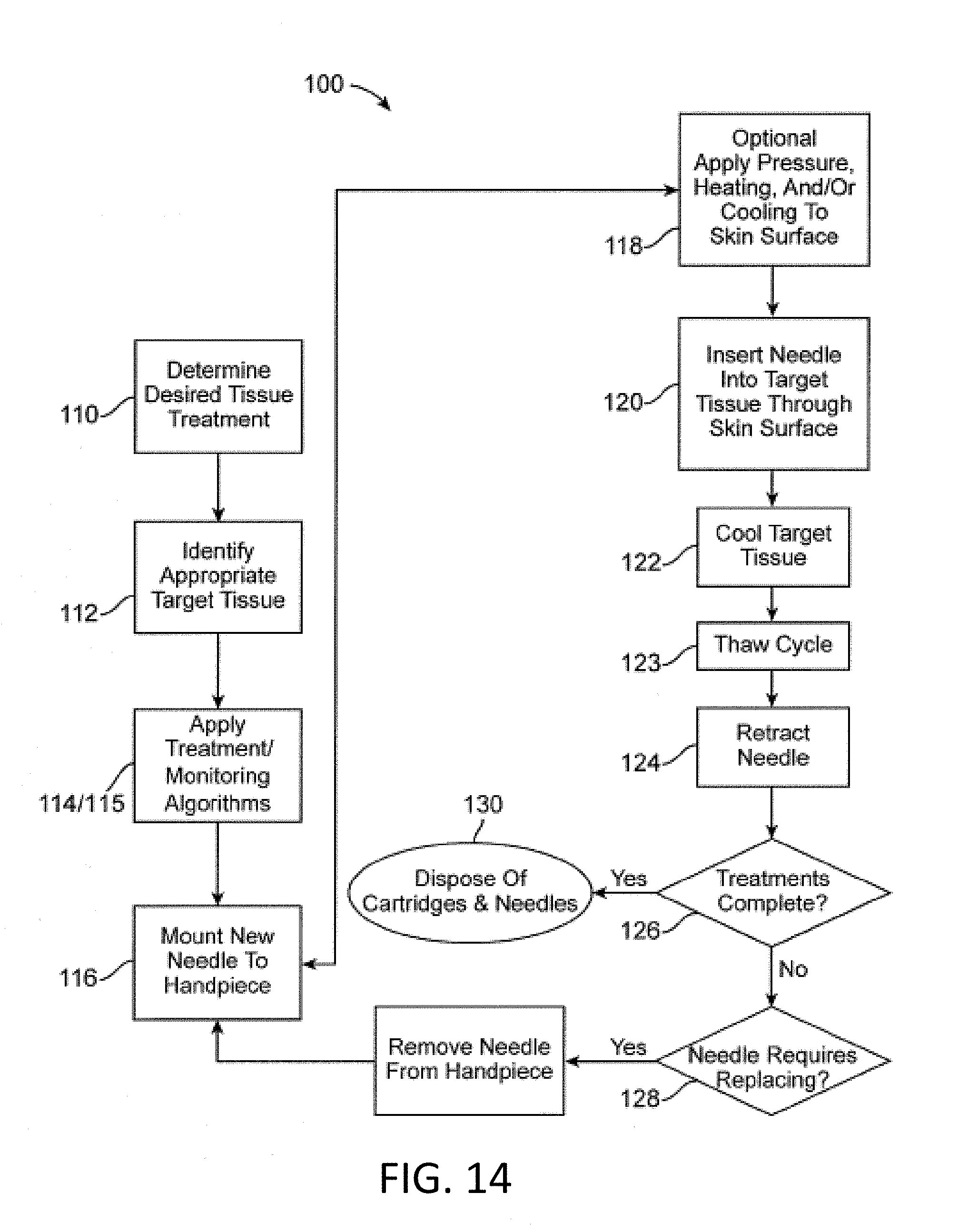
D00016

D00017
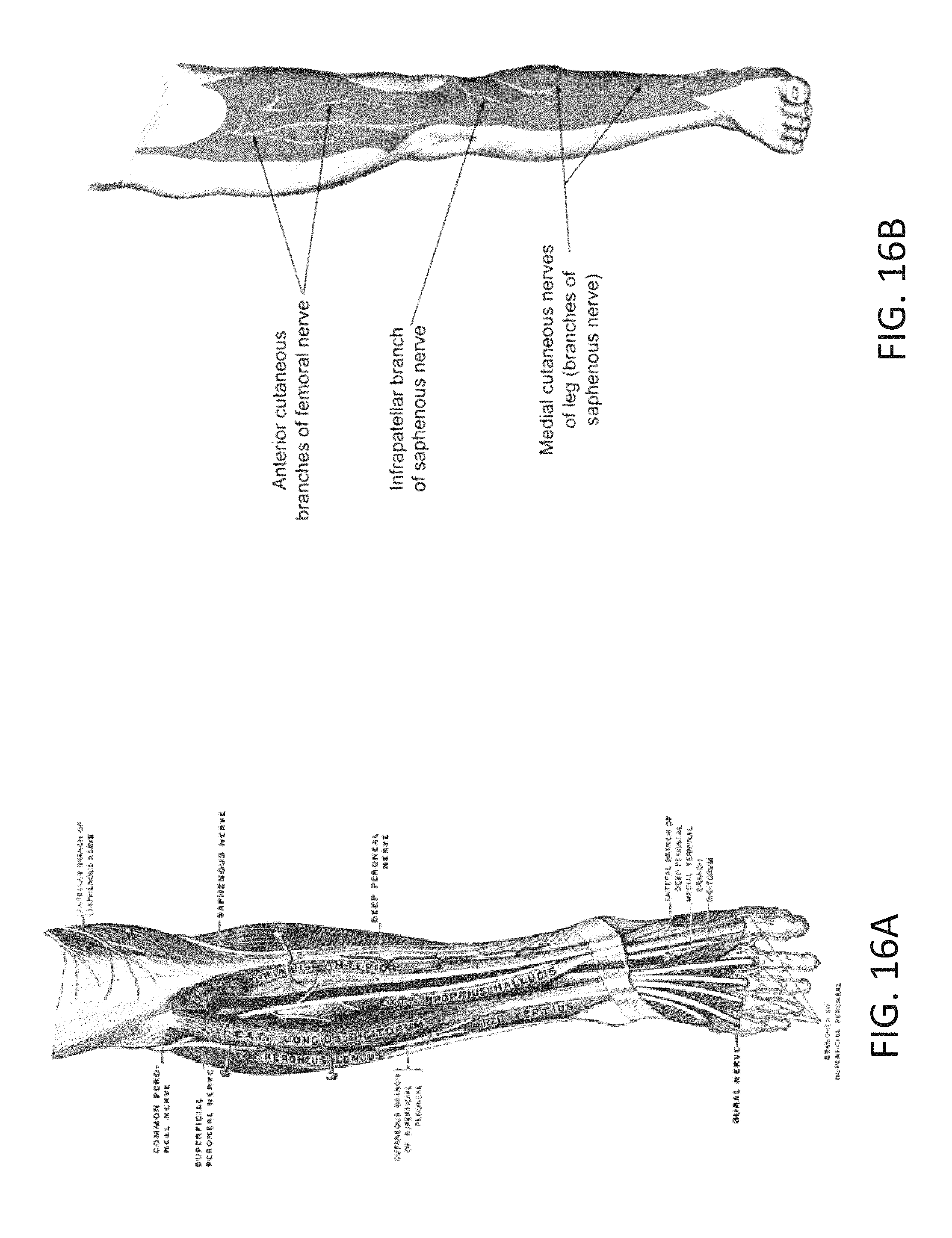
D00018

D00019

D00020

D00021

D00022

D00023

D00024
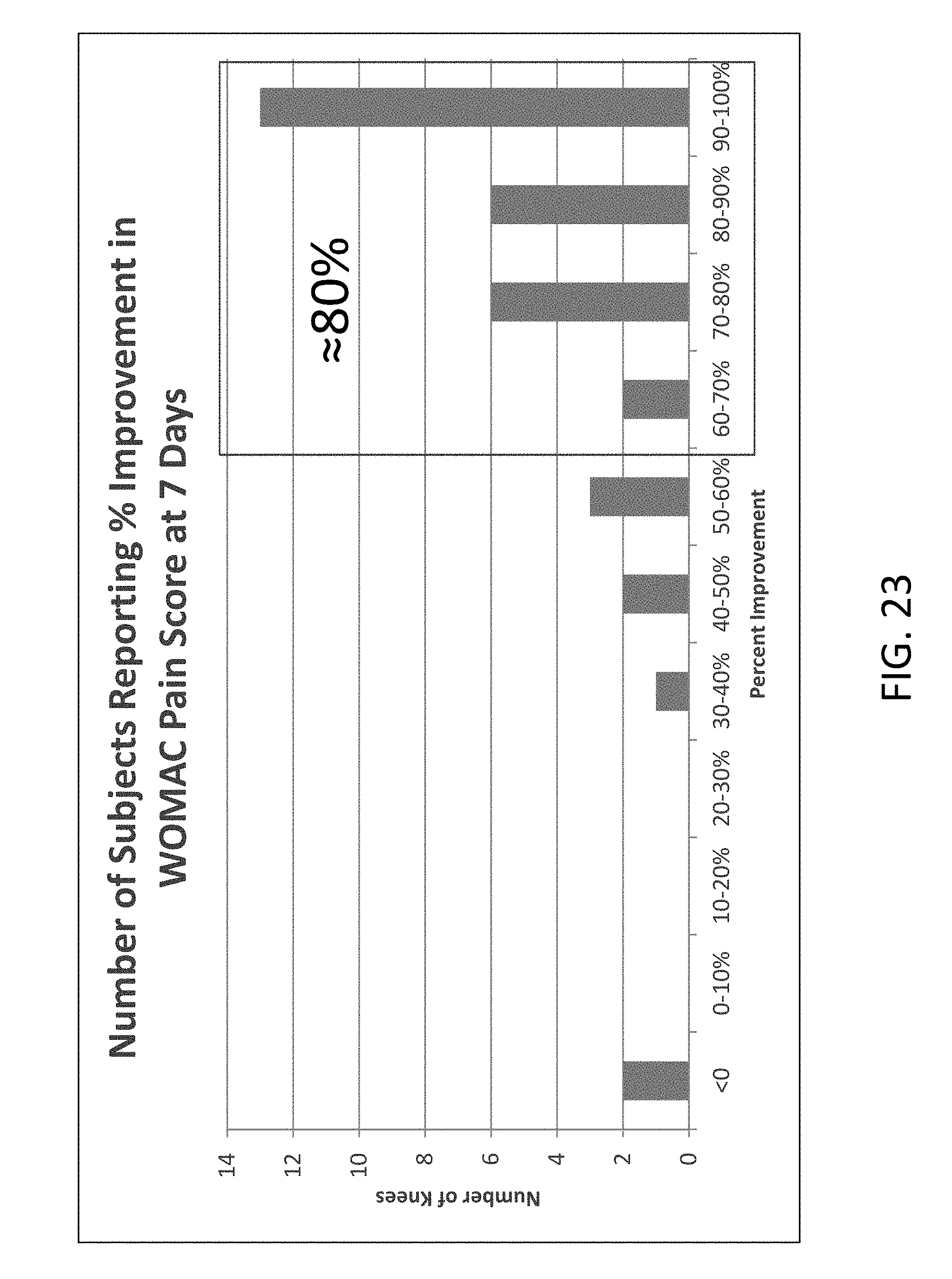
D00025

D00026
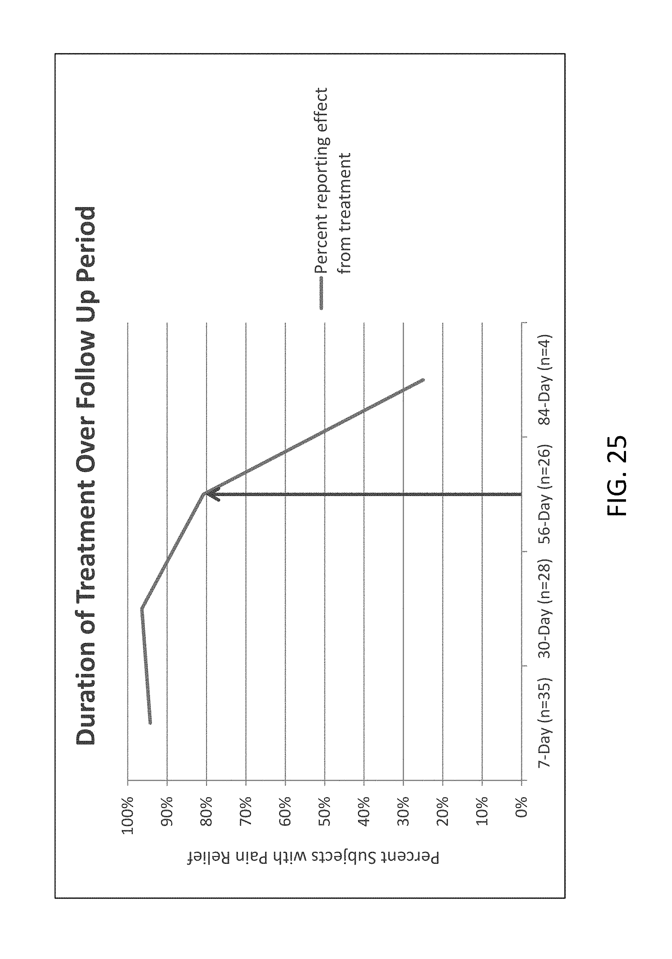
D00027

D00028

XML
uspto.report is an independent third-party trademark research tool that is not affiliated, endorsed, or sponsored by the United States Patent and Trademark Office (USPTO) or any other governmental organization. The information provided by uspto.report is based on publicly available data at the time of writing and is intended for informational purposes only.
While we strive to provide accurate and up-to-date information, we do not guarantee the accuracy, completeness, reliability, or suitability of the information displayed on this site. The use of this site is at your own risk. Any reliance you place on such information is therefore strictly at your own risk.
All official trademark data, including owner information, should be verified by visiting the official USPTO website at www.uspto.gov. This site is not intended to replace professional legal advice and should not be used as a substitute for consulting with a legal professional who is knowledgeable about trademark law.