Vacuum brush
Blouin
U.S. patent number 10,314,449 [Application Number 14/325,997] was granted by the patent office on 2019-06-11 for vacuum brush. This patent grant is currently assigned to iRobot Corporation. The grantee listed for this patent is iRobot Corporation. Invention is credited to Matthew Blouin.


View All Diagrams
| United States Patent | 10,314,449 |
| Blouin | June 11, 2019 |
Vacuum brush
Abstract
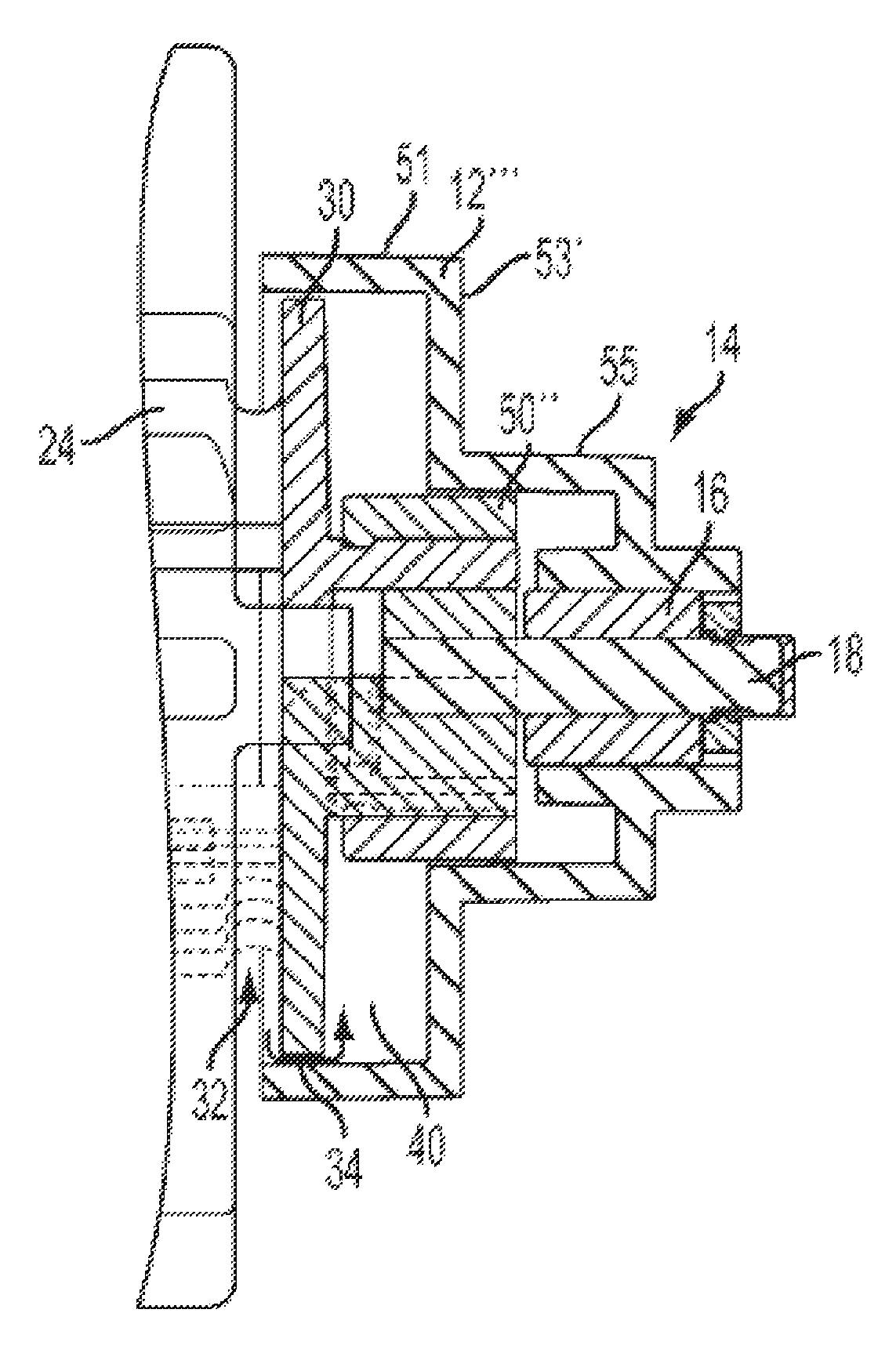
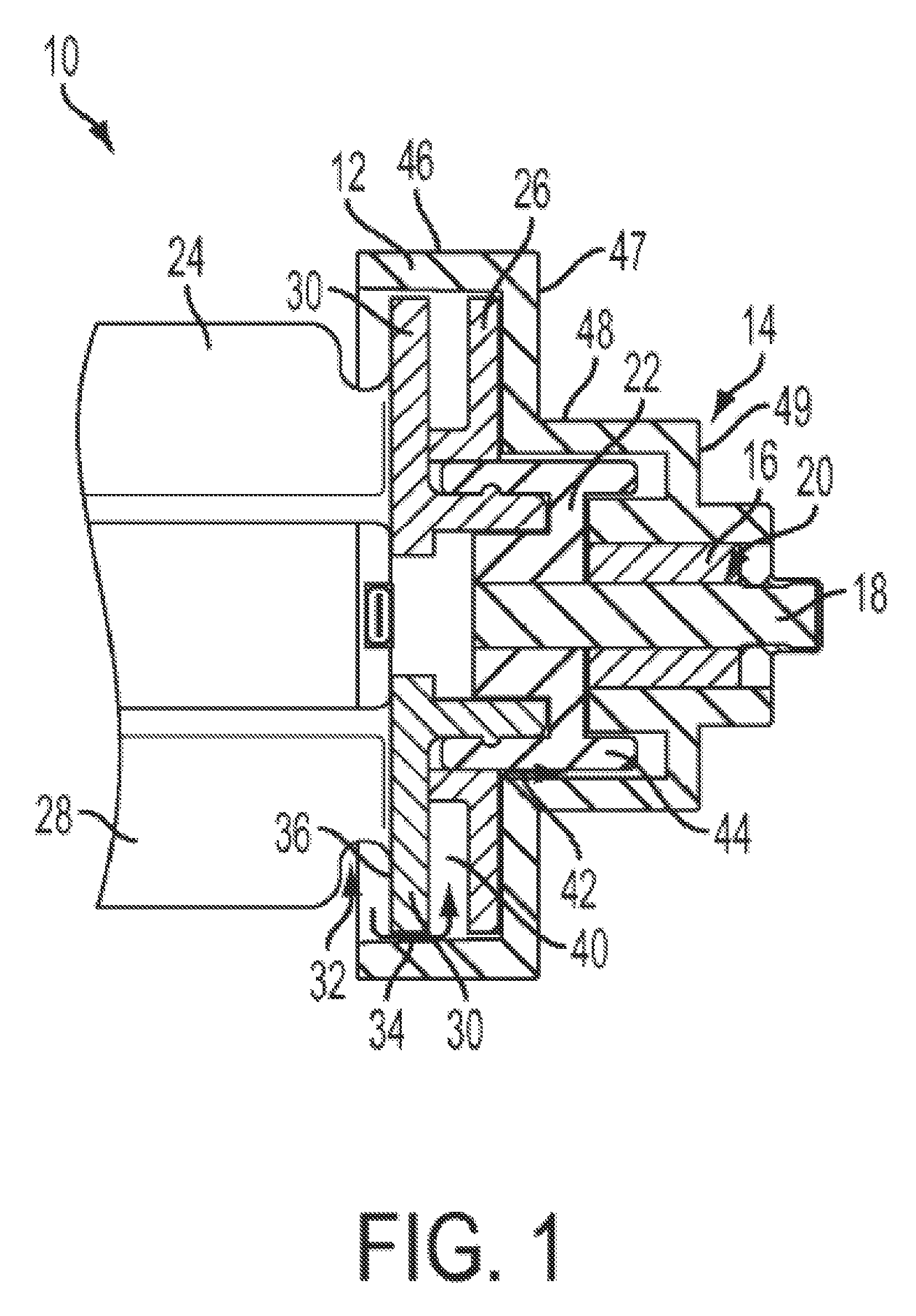
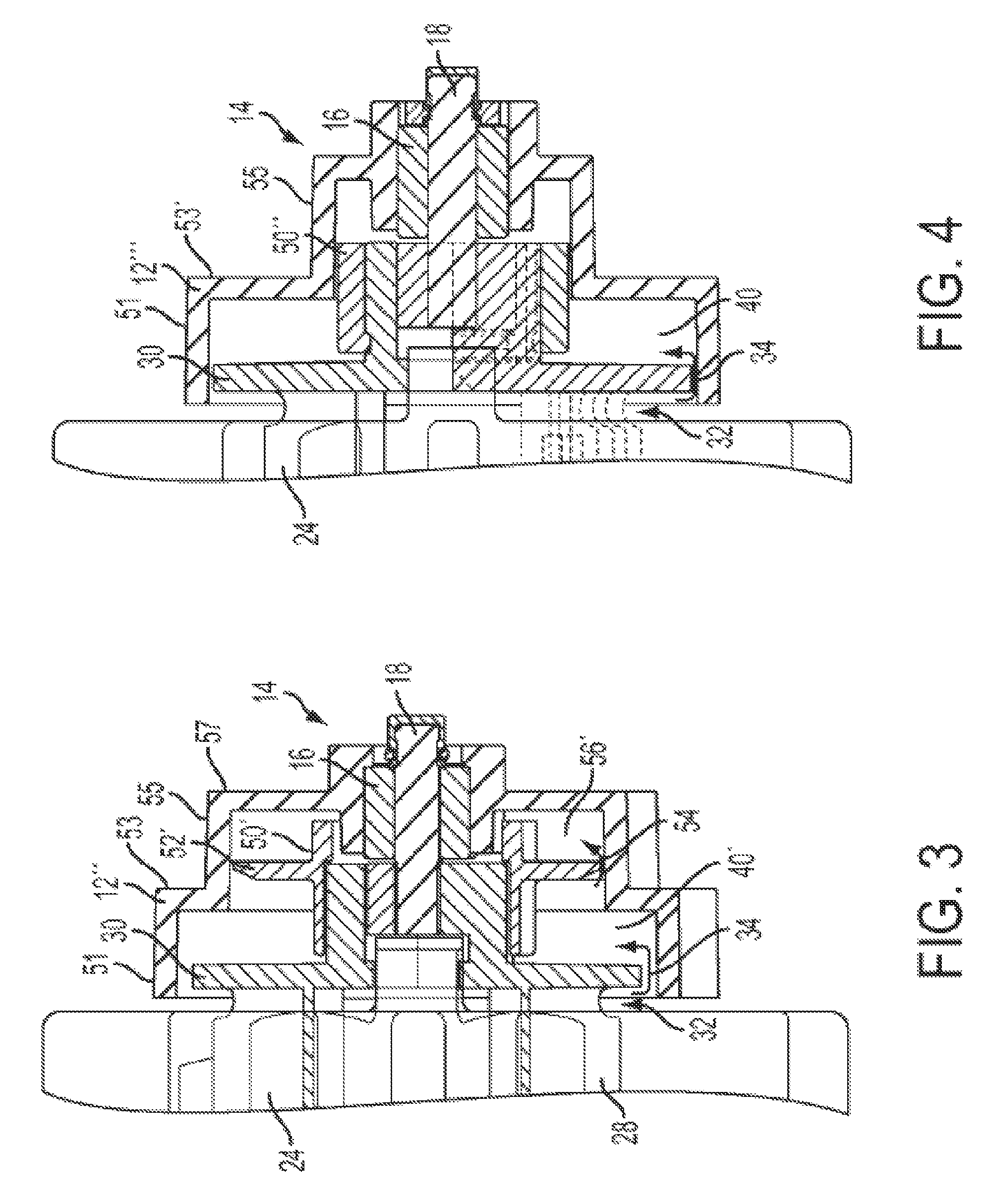
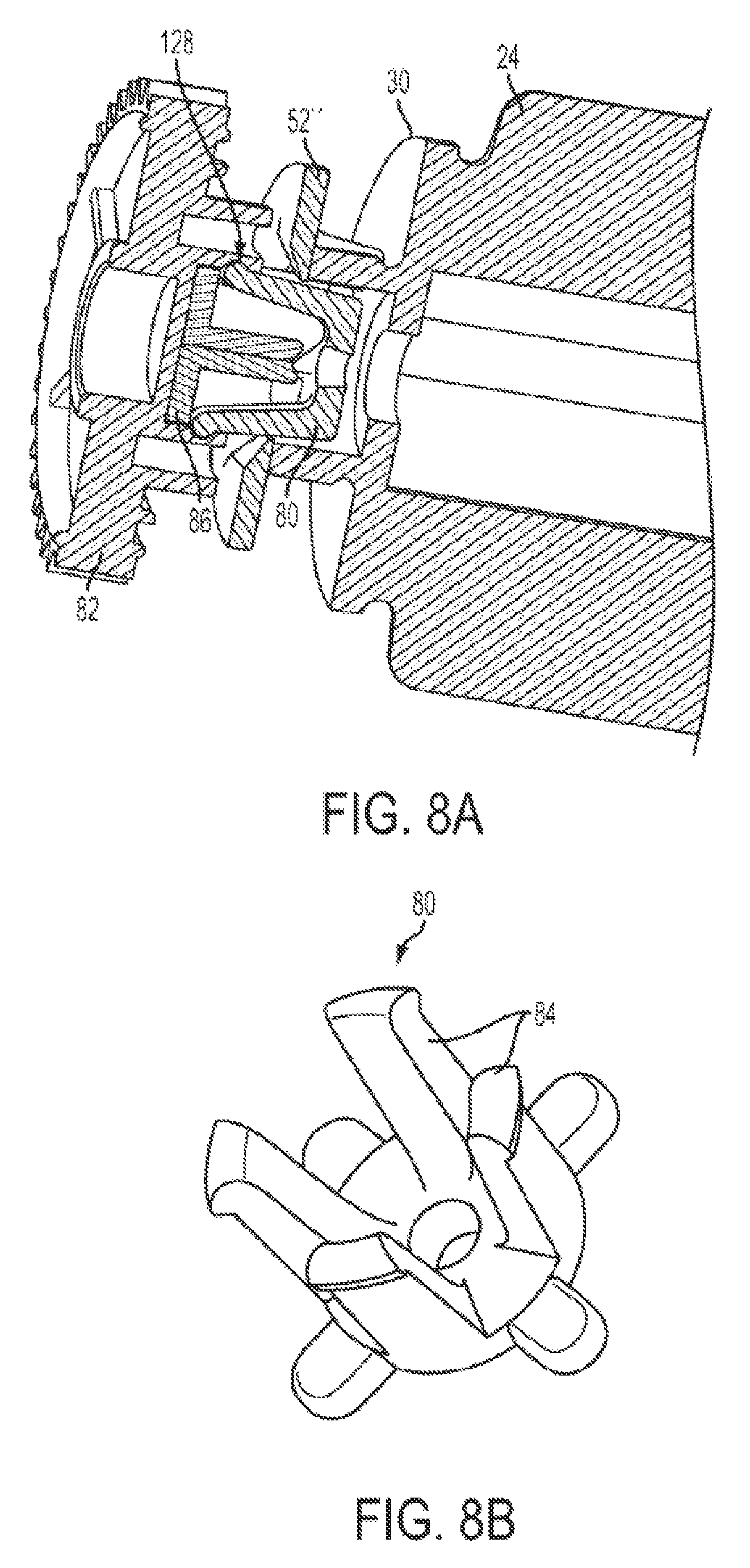
A rotating cleaning element configured to be inserted in a cleaning head compartment of a robotic vacuum, the rotating cleaning element including: a drive end including a drive protrusion configured to engage a drive mechanism of the cleaning head compartment; a bearing end and a shroud configured to surround at least a portion of the bearing end to lessen an amount of hair and similar matter that reaches the bearing; and a central member extending between the bearing end and the drive end.
| Inventors: | Blouin; Matthew (Townsend, MA) | ||||||||||
|---|---|---|---|---|---|---|---|---|---|---|---|
| Applicant: |
|
||||||||||
| Assignee: | iRobot Corporation (Bedford,
MA) |
||||||||||
| Family ID: | 43969419 | ||||||||||
| Appl. No.: | 14/325,997 | ||||||||||
| Filed: | July 8, 2014 |
Prior Publication Data
| Document Identifier | Publication Date | |
|---|---|---|
| US 20140317879 A1 | Oct 30, 2014 | |
Related U.S. Patent Documents
| Application Number | Filing Date | Patent Number | Issue Date | ||
|---|---|---|---|---|---|
| 13028996 | Feb 16, 2011 | 8800107 | |||
| 61304886 | Feb 16, 2010 | ||||
| Current U.S. Class: | 1/1 |
| Current CPC Class: | A47L 9/0427 (20130101); A47L 9/0455 (20130101); A47L 9/0477 (20130101) |
| Current International Class: | A47L 9/04 (20060101) |
| Field of Search: | ;15/383-392 |
References Cited [Referenced By]
U.S. Patent Documents
| 1755054 | April 1930 | Darst |
| 1780221 | November 1930 | Buchmann |
| 1970302 | August 1934 | Gerhardt |
| 1999696 | April 1935 | Kitto |
| 2136324 | November 1938 | John |
| 2176769 | October 1939 | Martinet |
| 2302111 | November 1942 | Dow et al. |
| 2353621 | July 1944 | Sav et al. |
| 2770825 | November 1956 | Pullen |
| 3119369 | January 1964 | Harland et al. |
| 3166138 | January 1965 | Dunn |
| 3216047 | November 1965 | Carl-Oskar |
| 3333564 | August 1967 | Waters |
| 3375375 | March 1968 | Robert et al. |
| 3381652 | May 1968 | Schaefer et al. |
| 3457575 | July 1969 | Bienek |
| 3550714 | December 1970 | Bellinger |
| 3569727 | March 1971 | Aggarwal et al. |
| 3639941 | February 1972 | Kirwan et al. |
| 3674316 | July 1972 | De Brey |
| 3678882 | July 1972 | Kinsella |
| 3744586 | July 1973 | Leinauer |
| 3756667 | September 1973 | Bombardier et al. |
| 3809004 | May 1974 | Leonheart |
| 3816004 | June 1974 | Bignardi |
| 3845831 | November 1974 | James |
| RE28268 | December 1974 | Autrand |
| 3853086 | December 1974 | Asplund |
| 3863285 | February 1975 | Hukuba |
| 3888181 | June 1975 | Kups |
| 3937174 | February 1976 | Haaga |
| 3952361 | April 1976 | Wilkins |
| 3989311 | November 1976 | Debrey |
| 3989931 | November 1976 | Phillips |
| 3993017 | November 1976 | De brey |
| 4004313 | January 1977 | Capra et al. |
| 4012681 | March 1977 | Finger et al. |
| 4070170 | January 1978 | Leinfelt |
| 4099284 | July 1978 | Shinozaki et al. |
| 4119900 | October 1978 | Kremnitz |
| 4175589 | November 1979 | Nakamura et al. |
| 4175892 | November 1979 | De brey |
| 4196727 | April 1980 | Verkaart et al. |
| 4198727 | April 1980 | Farmer |
| 4199838 | April 1980 | Simonsson |
| 4209254 | June 1980 | Reymond et al. |
| 4219902 | September 1980 | DeMaagd |
| D258901 | April 1981 | Keyworth |
| 4297578 | October 1981 | Carter |
| 4306329 | December 1981 | Yokoi |
| 4309758 | January 1982 | Halsall et al. |
| 4328545 | May 1982 | Halsall et al. |
| 4367403 | January 1983 | Miller |
| 4369543 | January 1983 | Chen et al. |
| 4401909 | August 1983 | Gorsek |
| 4416033 | November 1983 | Specht |
| 4429430 | February 1984 | Lyman |
| 4445245 | May 1984 | Lu |
| 4465370 | August 1984 | Yuasa et al. |
| 4477998 | October 1984 | You |
| 4481692 | November 1984 | Kurz |
| 4482960 | November 1984 | Pryor |
| 4492058 | January 1985 | Goldfarb et al. |
| 4513469 | April 1985 | Godfrey et al. |
| D278732 | May 1985 | Ohkado |
| 4518437 | May 1985 | Sommer |
| 4534637 | August 1985 | Suzuki et al. |
| 4556313 | December 1985 | Miller, Jr. et al. |
| 4575211 | March 1986 | Matsumura et al. |
| 4580311 | April 1986 | Kurz |
| 4601082 | July 1986 | Kurz |
| 4618213 | October 1986 | Chen |
| 4620285 | October 1986 | Perdue |
| 4624026 | November 1986 | Olson et al. |
| 4626995 | December 1986 | Lofgren et al. |
| 4628454 | December 1986 | Ito |
| 4638445 | January 1987 | Mattaboni |
| 4644156 | February 1987 | Takahashi et al. |
| 4649504 | March 1987 | Krouglicof et al. |
| 4652917 | March 1987 | Miller |
| 4654492 | March 1987 | Koerner et al. |
| 4654924 | April 1987 | Getz et al. |
| 4660969 | April 1987 | Sorimachi et al. |
| 4662854 | May 1987 | Fang |
| 4674048 | June 1987 | Okumura |
| 4679152 | July 1987 | Perdue |
| 4680827 | July 1987 | Hummel |
| 4696074 | September 1987 | Cavalli et al. |
| D292223 | October 1987 | Trumbull |
| 4700301 | October 1987 | Dyke |
| 4700427 | October 1987 | Knepper |
| 4703820 | November 1987 | Reinaud |
| 4710020 | December 1987 | Maddox et al. |
| 4716621 | January 1988 | Zoni |
| 4728801 | March 1988 | O'Connor |
| 4733343 | March 1988 | Yoneda et al. |
| 4733430 | March 1988 | Westergren |
| 4733431 | March 1988 | Martin |
| 4735136 | April 1988 | Lee et al. |
| 4735138 | April 1988 | Gawler et al. |
| 4748336 | May 1988 | Fujie et al. |
| 4748833 | June 1988 | Nagasawa |
| 4756049 | July 1988 | Uehara |
| 4767213 | August 1988 | Hummel |
| 4769700 | September 1988 | Pryor |
| 4777416 | October 1988 | George, II et al. |
| D298766 | November 1988 | Tanno et al. |
| 4782550 | November 1988 | Jacobs |
| 4796198 | January 1989 | Boultinghouse et al. |
| 4806751 | February 1989 | Abe et al. |
| 4811228 | March 1989 | Hyyppa |
| 4813906 | March 1989 | Matsuyama et al. |
| 4815157 | March 1989 | Tsuchiya |
| 4817000 | March 1989 | Eberhardt |
| 4818875 | April 1989 | Weiner |
| 4829442 | May 1989 | Kadonoff et al. |
| 4829626 | May 1989 | Harkonen et al. |
| 4832098 | May 1989 | Palinkas et al. |
| 4851661 | July 1989 | Everett, Jr. |
| 4854000 | August 1989 | Takimoto |
| 4854006 | August 1989 | Nishimura et al. |
| 4855915 | August 1989 | Dallaire |
| 4857912 | August 1989 | Everett, Jr. et al. |
| 4858132 | August 1989 | Holmquist |
| 4867570 | September 1989 | Sorimachi et al. |
| 4880474 | November 1989 | Koharagi et al. |
| 4887415 | December 1989 | Martin |
| 4891762 | January 1990 | Chotiros |
| 4893025 | January 1990 | Lee |
| 4901394 | February 1990 | Nakamura et al. |
| 4905151 | February 1990 | Weiman et al. |
| 4912643 | March 1990 | Beirne |
| 4918441 | April 1990 | Bohman |
| 4919224 | April 1990 | Shyu et al. |
| 4919489 | April 1990 | Kopsco |
| 4920060 | April 1990 | Parrent, Jr. et al. |
| 4920605 | May 1990 | Takashima |
| 4933864 | June 1990 | Evans, Jr. et al. |
| 4937912 | July 1990 | Kurz |
| 4953253 | September 1990 | Fukuda et al. |
| 4954962 | September 1990 | Evans, Jr. et al. |
| 4955714 | September 1990 | Stotler et al. |
| 4956891 | September 1990 | Wulff |
| 4961303 | October 1990 | McCarty et al. |
| 4961304 | October 1990 | Ovsborn et al. |
| 4962453 | October 1990 | Pong, Jr. et al. |
| 4971591 | November 1990 | Raviv et al. |
| 4973912 | November 1990 | Kaminski et al. |
| 4974283 | December 1990 | Holsten et al. |
| 4977618 | December 1990 | Allen |
| 4977639 | December 1990 | Takahashi et al. |
| 4986663 | January 1991 | Cecchi et al. |
| 5001635 | March 1991 | Yasutomi et al. |
| 5002145 | March 1991 | Wakaumi et al. |
| 5012886 | May 1991 | Jonas et al. |
| 5018240 | May 1991 | Holman |
| 5020186 | June 1991 | Lessig, III et al. |
| 5022812 | June 1991 | Coughlan et al. |
| 5023788 | June 1991 | Kitazume et al. |
| 5024529 | June 1991 | Svetkoff et al. |
| D318500 | July 1991 | Malewicki et al. |
| 5032775 | July 1991 | Mizuno et al. |
| 5033151 | July 1991 | Kraft et al. |
| 5033291 | July 1991 | Podoloff et al. |
| 5040116 | August 1991 | Evans, Jr. et al. |
| 5045769 | September 1991 | Everett, Jr. |
| 5049802 | September 1991 | Mintus et al. |
| 5051906 | September 1991 | Evans, Jr. et al. |
| 5062819 | November 1991 | Mallory |
| 5070567 | December 1991 | Holland |
| 5084934 | February 1992 | Lessig, III et al. |
| 5086535 | February 1992 | Grossmeyer et al. |
| 5090321 | February 1992 | Abouav |
| 5093955 | March 1992 | Blehert et al. |
| 5094311 | March 1992 | Akeel |
| 5105502 | April 1992 | Takashima |
| 5105550 | April 1992 | Shenoha |
| 5109566 | May 1992 | Kobayashi et al. |
| 5115538 | May 1992 | Cochran et al. |
| 5127128 | July 1992 | Lee |
| 5136675 | August 1992 | Hodson |
| 5136750 | August 1992 | Takashima et al. |
| 5142985 | September 1992 | Stearns et al. |
| 5144471 | September 1992 | Takanashi et al. |
| 5144714 | September 1992 | Mori et al. |
| 5144715 | September 1992 | Matsuyo et al. |
| 5152028 | October 1992 | Hirano |
| 5152202 | October 1992 | Strauss |
| 5155684 | October 1992 | Burke et al. |
| 5163202 | November 1992 | Kawakami et al. |
| 5163320 | November 1992 | Goshima et al. |
| 5164579 | November 1992 | Pryor et al. |
| 5165064 | November 1992 | Mattaboni |
| 5170352 | December 1992 | McTamaney et al. |
| 5173881 | December 1992 | Sindle |
| 5182833 | February 1993 | Yamaguchi et al. |
| 5202742 | April 1993 | Frank et al. |
| 5204814 | April 1993 | Noonan et al. |
| 5206500 | April 1993 | Decker et al. |
| 5208521 | May 1993 | Aoyama |
| 5216777 | June 1993 | Moro et al. |
| 5227985 | July 1993 | DeMenthon |
| 5233682 | August 1993 | Abe et al. |
| 5239720 | August 1993 | Wood et al. |
| 5251358 | October 1993 | Moro et al. |
| 5261139 | November 1993 | Lewis |
| 5272785 | December 1993 | Stegens |
| 5276618 | January 1994 | Everett, Jr. |
| 5276939 | January 1994 | Uenishi |
| 5277064 | January 1994 | Knigga et al. |
| 5279672 | January 1994 | Betker et al. |
| 5284452 | February 1994 | Corona |
| 5284522 | February 1994 | Kobayashi et al. |
| 5293955 | March 1994 | Lee |
| D345707 | April 1994 | Alister |
| 5303448 | April 1994 | Hennessey et al. |
| 5307273 | April 1994 | Oh et al. |
| 5309592 | May 1994 | Hiratsuka |
| 5310379 | May 1994 | Hippely et al. |
| 5315227 | May 1994 | Pierson et al. |
| 5319827 | June 1994 | Yang |
| 5319828 | June 1994 | Waldhauser et al. |
| 5321614 | June 1994 | Ashworth |
| 5323483 | June 1994 | Baeg |
| 5324948 | June 1994 | Dudar et al. |
| 5341186 | August 1994 | Kato |
| 5341540 | August 1994 | Soupert et al. |
| 5341549 | August 1994 | Wirtz et al. |
| 5345649 | September 1994 | Whitlow |
| 5353224 | October 1994 | Lee et al. |
| 5363305 | November 1994 | Cox et al. |
| 5363935 | November 1994 | Schempf et al. |
| 5369347 | November 1994 | Yoo |
| 5369838 | December 1994 | Wood et al. |
| 5386862 | February 1995 | Glover et al. |
| 5399951 | March 1995 | Lavallee et al. |
| 5400244 | March 1995 | Watanabe et al. |
| 5404612 | April 1995 | Ishikawa |
| 5410479 | April 1995 | Coker |
| 5435038 | July 1995 | Sauers |
| 5435405 | July 1995 | Schempf et al. |
| 5440216 | August 1995 | Kim |
| 5442358 | August 1995 | Keeler et al. |
| 5444965 | August 1995 | Colens |
| 5446356 | August 1995 | Kim |
| 5446445 | August 1995 | Bloomfield et al. |
| 5451135 | September 1995 | Schempf et al. |
| 5452490 | September 1995 | Brundula et al. |
| 5454129 | October 1995 | Kell |
| 5455982 | October 1995 | Armstrong et al. |
| 5465451 | November 1995 | Stegens |
| 5465525 | November 1995 | Mifune et al. |
| 5465619 | November 1995 | Sotack et al. |
| 5467273 | November 1995 | Faibish et al. |
| 5471560 | November 1995 | Allard et al. |
| 5491670 | February 1996 | Weber |
| 5497529 | March 1996 | Boesi et al. |
| 5498948 | March 1996 | Bruni et al. |
| 5502638 | March 1996 | Takenaka |
| 5505072 | April 1996 | Oreper |
| 5507067 | April 1996 | Hoekstra et al. |
| 5510893 | April 1996 | Suzuki |
| 5511147 | April 1996 | Abdel-Malek |
| 5515572 | May 1996 | Hoekstra et al. |
| 5534762 | July 1996 | Kim |
| 5537017 | July 1996 | Feiten et al. |
| 5537711 | July 1996 | Tseng |
| 5539953 | July 1996 | Kurz |
| 5542146 | August 1996 | Hoekstra et al. |
| 5542148 | August 1996 | Young |
| 5546631 | August 1996 | Chambon |
| 5548511 | August 1996 | Bancroft |
| 5551525 | September 1996 | Pack et al. |
| 5553349 | September 1996 | Kilstrom et al. |
| 5555587 | September 1996 | Guha |
| 5560077 | October 1996 | Crotchett |
| 5568589 | October 1996 | Hwang |
| D375592 | November 1996 | Ljunggren |
| 5608306 | March 1997 | Rybeck et al. |
| 5608894 | March 1997 | Kawakami et al. |
| 5608944 | March 1997 | Gordon |
| 5610488 | March 1997 | Miyazawa |
| 5611106 | March 1997 | Wulff |
| 5611108 | March 1997 | Knowlton et al. |
| 5613261 | March 1997 | Kawakami et al. |
| 5613269 | March 1997 | Miwa |
| 5621291 | April 1997 | Lee |
| 5622236 | April 1997 | Azumi et al. |
| 5634237 | June 1997 | Paranjpe |
| 5634239 | June 1997 | Tuvin et al. |
| 5636402 | June 1997 | Kubo et al. |
| 5642299 | June 1997 | Hardin et al. |
| 5646494 | July 1997 | Han |
| 5647554 | July 1997 | Ikegami et al. |
| 5650702 | July 1997 | Azumi |
| 5652489 | July 1997 | Kawakami |
| 5682313 | October 1997 | Edlund et al. |
| 5682839 | November 1997 | Grimsley et al. |
| 5696675 | December 1997 | Nakamura et al. |
| 5698861 | December 1997 | Oh |
| 5709007 | January 1998 | Chiang |
| 5710506 | January 1998 | Broell et al. |
| 5714119 | February 1998 | Kawagoe et al. |
| 5717169 | February 1998 | Liang et al. |
| 5717484 | February 1998 | Hamaguchi et al. |
| 5720077 | February 1998 | Nakamura et al. |
| 5732401 | March 1998 | Conway |
| 5735959 | April 1998 | Kubo et al. |
| 5745235 | April 1998 | Vercammen et al. |
| 5752871 | May 1998 | Tsuzuki |
| 5756904 | May 1998 | Oreper et al. |
| 5761762 | June 1998 | Kubo |
| 5764888 | June 1998 | Bolan et al. |
| 5767437 | June 1998 | Rogers |
| 5767960 | June 1998 | Orman |
| 5777596 | July 1998 | Herbert |
| 5778486 | July 1998 | Kim |
| 5781697 | July 1998 | Jeong |
| 5781960 | July 1998 | Kilstrom et al. |
| 5786602 | July 1998 | Pryor et al. |
| 5787545 | August 1998 | Colens |
| 5793900 | August 1998 | Nourbakhsh et al. |
| 5794297 | August 1998 | Muta |
| 5812267 | September 1998 | Everett, Jr. et al. |
| 5814808 | September 1998 | Takada et al. |
| 5815880 | October 1998 | Nakanishi |
| 5815884 | October 1998 | Imamura et al. |
| 5819008 | October 1998 | Asama et al. |
| 5819360 | October 1998 | Fujii |
| 5819936 | October 1998 | Saveliev et al. |
| 5820821 | October 1998 | Kawagoe et al. |
| 5821730 | October 1998 | Drapkin |
| 5825981 | October 1998 | Matsuda |
| 5828770 | October 1998 | Leis et al. |
| 5831597 | November 1998 | West et al. |
| 5839156 | November 1998 | Park et al. |
| 5839532 | November 1998 | Yoshiji et al. |
| 5841259 | November 1998 | Kim et al. |
| 5867800 | February 1999 | Leif |
| 5869910 | February 1999 | Colens |
| 5896611 | April 1999 | Haaga |
| 5903124 | May 1999 | Kawakami |
| 5905209 | May 1999 | Oreper |
| 5907886 | June 1999 | Buscher |
| 5910700 | June 1999 | Crotzer |
| 5911260 | June 1999 | Suzuki |
| 5916008 | June 1999 | Wong |
| 5924167 | July 1999 | Wright et al. |
| 5926909 | July 1999 | McGee |
| 5933102 | August 1999 | Miller et al. |
| 5933913 | August 1999 | Wright et al. |
| 5935179 | August 1999 | Kleiner et al. |
| 5940346 | August 1999 | Sadowsky et al. |
| 5940927 | August 1999 | Haegermarck et al. |
| 5940930 | August 1999 | Oh et al. |
| 5942869 | August 1999 | Katou et al. |
| 5943730 | August 1999 | Boomgaarden |
| 5943733 | August 1999 | Tagliaferri |
| 5947225 | September 1999 | Kawakami et al. |
| 5950408 | September 1999 | Schaedler |
| 5959423 | September 1999 | Nakanishi et al. |
| 5968281 | October 1999 | Wright et al. |
| 5974348 | October 1999 | Rocks |
| 5974365 | October 1999 | Mitchell |
| 5983448 | November 1999 | Wright et al. |
| 5984880 | November 1999 | Lander et al. |
| 5987383 | November 1999 | Keller et al. |
| 5989700 | November 1999 | Krivopal |
| 5991951 | November 1999 | Kubo et al. |
| 5995883 | November 1999 | Nishikado |
| 5995884 | November 1999 | Allen et al. |
| 5996167 | December 1999 | Close |
| 5998953 | December 1999 | Nakamura et al. |
| 5998971 | December 1999 | Corbridge |
| 6000088 | December 1999 | Wright et al. |
| 6003198 | December 1999 | Stegens |
| 6009358 | December 1999 | Angott et al. |
| 6021545 | February 2000 | Delgado et al. |
| 6023813 | February 2000 | Thatcher et al. |
| 6023814 | February 2000 | Imamura |
| 6025687 | February 2000 | Himeda et al. |
| 6026539 | February 2000 | Mouw et al. |
| 6030464 | February 2000 | Azevedo |
| 6030465 | February 2000 | Marcussen et al. |
| 6032542 | March 2000 | Warnick et al. |
| 6036572 | March 2000 | Sze |
| 6038501 | March 2000 | Kawakami |
| 6040669 | March 2000 | Hog |
| 6041471 | March 2000 | Charky et al. |
| 6041472 | March 2000 | Kasen et al. |
| 6046800 | April 2000 | Ohtomo et al. |
| 6049620 | April 2000 | Dickinson et al. |
| 6052821 | April 2000 | Chouly et al. |
| 6055042 | April 2000 | Sarangapani |
| 6055702 | May 2000 | Imamura et al. |
| 6061868 | May 2000 | Moritsch et al. |
| 6065182 | May 2000 | Wright et al. |
| 6073432 | June 2000 | Schaedler |
| 6076025 | June 2000 | Ueno et al. |
| 6076026 | June 2000 | Jambhekar et al. |
| 6076226 | June 2000 | Reed |
| 6076227 | June 2000 | Schallig et al. |
| 6081257 | June 2000 | Zeller |
| 6088020 | July 2000 | Mor |
| 6094775 | August 2000 | Behmer |
| 6099091 | August 2000 | Campbell |
| 6101670 | August 2000 | Song |
| 6101671 | August 2000 | Wright et al. |
| 6108031 | August 2000 | King et al. |
| 6108067 | August 2000 | Okamoto |
| 6108076 | August 2000 | Hanseder |
| 6108269 | August 2000 | Kabel |
| 6108597 | August 2000 | Kirchner et al. |
| 6112143 | August 2000 | Allen et al. |
| 6112996 | September 2000 | Matsuo |
| 6119057 | September 2000 | Kawagoe |
| 6122798 | September 2000 | Kobayashi et al. |
| 6124694 | September 2000 | Bancroft et al. |
| 6125498 | October 2000 | Roberts et al. |
| 6131237 | October 2000 | Kasper et al. |
| 6138063 | October 2000 | Himeda |
| 6142252 | November 2000 | Kinto et al. |
| 6146278 | November 2000 | Kobayashi |
| 6154279 | November 2000 | Thayer |
| 6154694 | November 2000 | Aoki et al. |
| 6160479 | December 2000 | .ANG.hlen et al. |
| 6167332 | December 2000 | Kurtzberg et al. |
| 6167587 | January 2001 | Kasper et al. |
| 6192548 | February 2001 | Huffman |
| 6216307 | April 2001 | Kaleta et al. |
| 6220865 | April 2001 | Macri et al. |
| 6226830 | May 2001 | Hendriks et al. |
| 6230362 | May 2001 | Kasper et al. |
| 6237741 | May 2001 | Guidetti |
| 6240342 | May 2001 | Fiegert et al. |
| 6243913 | June 2001 | Frank et al. |
| 6255793 | July 2001 | Peless et al. |
| 6259979 | July 2001 | Holmquist |
| 6261379 | July 2001 | Conrad et al. |
| 6263539 | July 2001 | Baig |
| 6263989 | July 2001 | Won |
| 6272936 | August 2001 | Oreper et al. |
| 6276478 | August 2001 | Hopkins et al. |
| 6278918 | August 2001 | Dickson et al. |
| 6282526 | August 2001 | Ganesh |
| 6283034 | September 2001 | Miles, Jr. |
| 6285778 | September 2001 | Nakajima et al. |
| 6285930 | September 2001 | Dickson et al. |
| 6300737 | October 2001 | Bergvall et al. |
| 6321337 | November 2001 | Reshef et al. |
| 6321515 | November 2001 | Colens |
| 6323570 | November 2001 | Nishimura et al. |
| 6324714 | December 2001 | Walz et al. |
| 6327741 | December 2001 | Reed |
| 6332400 | December 2001 | Meyer |
| 6339735 | January 2002 | Peless et al. |
| 6362875 | March 2002 | Burkley |
| 6370453 | April 2002 | Sommer |
| 6374155 | April 2002 | Wallach et al. |
| 6374157 | April 2002 | Takamura |
| 6381802 | May 2002 | Park |
| 6385515 | May 2002 | Dickson et al. |
| 6388013 | May 2002 | Saraf et al. |
| 6389329 | May 2002 | Colens |
| 6400048 | June 2002 | Nishimura et al. |
| 6401294 | June 2002 | Kasper |
| 6408226 | June 2002 | Byrne et al. |
| 6412141 | July 2002 | Kasper et al. |
| 6415203 | July 2002 | Inoue et al. |
| 6421870 | July 2002 | Basham et al. |
| 6427285 | August 2002 | Legatt et al. |
| 6430471 | August 2002 | Kintou et al. |
| 6431296 | August 2002 | Won |
| 6437227 | August 2002 | Theimer |
| 6437465 | August 2002 | Nishimura et al. |
| 6438456 | August 2002 | Feddema et al. |
| 6438793 | August 2002 | Miner et al. |
| 6442476 | August 2002 | Poropat |
| 6443509 | September 2002 | Levin et al. |
| 6444003 | September 2002 | Sutcliffe |
| 6446302 | September 2002 | Kasper et al. |
| 6454036 | September 2002 | Airey et al. |
| D464091 | October 2002 | Christianson |
| 6457206 | October 2002 | Judson |
| 6459955 | October 2002 | Bartsch et al. |
| 6463368 | October 2002 | Feiten et al. |
| 6465982 | October 2002 | Bergvall et al. |
| 6473167 | October 2002 | Odell |
| 6480762 | November 2002 | Uchikubo et al. |
| 6481515 | November 2002 | Kirkpatrick et al. |
| 6490539 | December 2002 | Dickson et al. |
| 6491127 | December 2002 | Holmberg et al. |
| 6493612 | December 2002 | Bisset et al. |
| 6493613 | December 2002 | Peless et al. |
| 6496754 | December 2002 | Song et al. |
| 6496755 | December 2002 | Wallach et al. |
| 6502657 | January 2003 | Kerrebrock et al. |
| 6504610 | January 2003 | Bauer et al. |
| 6507773 | January 2003 | Parker et al. |
| 6525509 | February 2003 | Petersson et al. |
| D471243 | March 2003 | Cioffi et al. |
| 6532404 | March 2003 | Colens |
| 6535793 | March 2003 | Allard |
| 6540607 | April 2003 | Mokris et al. |
| 6548982 | April 2003 | Papanikolopoulos et al. |
| 6553612 | April 2003 | Dyson et al. |
| 6556722 | April 2003 | Russell et al. |
| 6556892 | April 2003 | Kuroki et al. |
| 6557104 | April 2003 | Vu et al. |
| D474312 | May 2003 | Stephens et al. |
| 6563130 | May 2003 | Dworkowski et al. |
| 6571415 | June 2003 | Gerber et al. |
| 6571422 | June 2003 | Gordon et al. |
| 6572711 | June 2003 | Sclafani et al. |
| 6574536 | June 2003 | Kawagoe et al. |
| 6580246 | June 2003 | Jacobs |
| 6584376 | June 2003 | Van Kommer |
| 6586908 | July 2003 | Petersson et al. |
| 6587573 | July 2003 | Stam et al. |
| 6590222 | July 2003 | Bisset et al. |
| 6594551 | July 2003 | McKinney, Jr. et al. |
| 6594844 | July 2003 | Jones |
| D478884 | August 2003 | Slipy et al. |
| 6601265 | August 2003 | Burlington |
| 6604021 | August 2003 | Imai et al. |
| 6604022 | August 2003 | Parker et al. |
| 6605156 | August 2003 | Clark et al. |
| 6611120 | August 2003 | Song et al. |
| 6611734 | August 2003 | Parker et al. |
| 6611738 | August 2003 | Ruffner |
| 6615108 | September 2003 | Peless et al. |
| 6615885 | September 2003 | Ohm |
| 6622465 | September 2003 | Jerome et al. |
| 6624744 | September 2003 | Wilson et al. |
| 6625843 | September 2003 | Kim et al. |
| 6629028 | September 2003 | Paromtchik et al. |
| 6639659 | October 2003 | Granger |
| 6658325 | December 2003 | Zweig |
| 6658354 | December 2003 | Lin |
| 6658692 | December 2003 | Lenkiewicz et al. |
| 6658693 | December 2003 | Reed, Jr. |
| 6661239 | December 2003 | Ozick |
| 6662889 | December 2003 | De Fazio et al. |
| 6668951 | December 2003 | Won |
| 6670817 | December 2003 | Fournier et al. |
| 6671592 | December 2003 | Bisset et al. |
| 6687571 | February 2004 | Byrne et al. |
| 6690134 | February 2004 | Jones et al. |
| 6690993 | February 2004 | Foulke et al. |
| 6697147 | February 2004 | Ko et al. |
| 6711280 | March 2004 | Stafsudd et al. |
| 6732826 | May 2004 | Song et al. |
| 6737591 | May 2004 | Lapstun et al. |
| 6741054 | May 2004 | Koselka et al. |
| 6741364 | May 2004 | Lange et al. |
| 6748297 | June 2004 | Song et al. |
| 6756703 | June 2004 | Chang |
| 6760647 | July 2004 | Nourbakhsh et al. |
| 6764373 | July 2004 | Osawa et al. |
| 6769004 | July 2004 | Barrett |
| 6774596 | August 2004 | Bisset |
| 6779380 | August 2004 | Nieuwkamp |
| 6781338 | August 2004 | Jones et al. |
| 6809490 | October 2004 | Jones et al. |
| 6810305 | October 2004 | Kirkpatrick, Jr. |
| 6810559 | November 2004 | Mertes |
| 6830120 | December 2004 | Yashima et al. |
| 6832407 | December 2004 | Salem et al. |
| 6836701 | December 2004 | McKee |
| 6841963 | January 2005 | Song et al. |
| 6845297 | January 2005 | Allard |
| 6856811 | February 2005 | Burdue et al. |
| 6859010 | February 2005 | Jeon et al. |
| 6859682 | February 2005 | Naka et al. |
| 6860206 | March 2005 | Rudakevych et al. |
| 6865447 | March 2005 | Lau et al. |
| 6870792 | March 2005 | Chiappetta |
| 6871115 | March 2005 | Huang et al. |
| 6883201 | April 2005 | Jones et al. |
| 6886651 | May 2005 | Slocum et al. |
| 6888333 | May 2005 | Laby |
| 6901624 | June 2005 | Mori et al. |
| 6906702 | June 2005 | Tanaka et al. |
| 6914403 | July 2005 | Tsurumi |
| 6917854 | July 2005 | Bayer |
| 6925357 | August 2005 | Wang et al. |
| 6925679 | August 2005 | Wallach et al. |
| 6929548 | August 2005 | Wang |
| D510066 | September 2005 | Hickey et al. |
| 6938298 | September 2005 | Aasen |
| 6940291 | September 2005 | Ozick |
| 6941199 | September 2005 | Bottomley et al. |
| 6956348 | October 2005 | Landry et al. |
| 6957712 | October 2005 | Song et al. |
| 6960986 | November 2005 | Asama et al. |
| 6965209 | November 2005 | Jones et al. |
| 6965211 | November 2005 | Tsurumi |
| 6968592 | November 2005 | Takeuchi et al. |
| 6971140 | December 2005 | Kim |
| 6975246 | December 2005 | Trudeau |
| 6980229 | December 2005 | Ebersole, Jr. |
| 6985556 | January 2006 | Shanmugavel et al. |
| 6993954 | February 2006 | George et al. |
| 6999850 | February 2006 | McDonald |
| 7013527 | March 2006 | Thomas, Sr. et al. |
| 7024278 | April 2006 | Chiappetta et al. |
| 7024280 | April 2006 | Parker et al. |
| 7027893 | April 2006 | Perry et al. |
| 7030768 | April 2006 | Wanie |
| 7031805 | April 2006 | Lee et al. |
| 7032469 | April 2006 | Bailey |
| 7053578 | May 2006 | Diehl et al. |
| 7054716 | May 2006 | McKee et al. |
| 7055210 | June 2006 | Keppler et al. |
| 7057120 | June 2006 | Ma et al. |
| 7057643 | June 2006 | Iida et al. |
| 7065430 | June 2006 | Naka et al. |
| 7066291 | June 2006 | Martins et al. |
| 7069124 | June 2006 | Whittaker et al. |
| 7079923 | July 2006 | Abramson et al. |
| 7085623 | August 2006 | Siegers |
| 7085624 | August 2006 | Aldred et al. |
| 7113847 | September 2006 | Chmura et al. |
| 7133746 | November 2006 | Abramson et al. |
| 7142198 | November 2006 | Lee |
| 7148458 | December 2006 | Schell et al. |
| 7155308 | December 2006 | Jones |
| 7167775 | January 2007 | Abramson et al. |
| 7171285 | January 2007 | Kim et al. |
| 7173391 | February 2007 | Jones et al. |
| 7174238 | February 2007 | Zweig |
| 7188000 | March 2007 | Chiappetta et al. |
| 7193384 | March 2007 | Norman et al. |
| 7196487 | March 2007 | Jones et al. |
| 7201786 | April 2007 | Wegelin et al. |
| 7206677 | April 2007 | Hulden |
| 7211980 | May 2007 | Bruemmer et al. |
| 7225500 | June 2007 | Diehl et al. |
| 7246405 | July 2007 | Yan |
| 7248951 | July 2007 | Hulden |
| 7275280 | October 2007 | Haegermarck et al. |
| 7283892 | October 2007 | Boillot et al. |
| 7288912 | October 2007 | Landry et al. |
| 7318248 | January 2008 | Yan |
| 7320149 | January 2008 | Huffman et al. |
| 7324870 | January 2008 | Lee |
| 7328196 | February 2008 | Peters, II |
| 7332890 | February 2008 | Cohen et al. |
| 7352153 | April 2008 | Yan |
| 7359766 | April 2008 | Jeon et al. |
| 7360277 | April 2008 | Moshenrose et al. |
| 7363108 | April 2008 | Noda et al. |
| 7388879 | June 2008 | Sabe et al. |
| 7389166 | June 2008 | Harwig et al. |
| 7408157 | August 2008 | Yan |
| 7418762 | September 2008 | Arai et al. |
| 7430455 | September 2008 | Casey et al. |
| 7430462 | September 2008 | Chiu et al. |
| 7441298 | October 2008 | Svendsen et al. |
| 7444206 | October 2008 | Abramson et al. |
| 7448113 | November 2008 | Jones et al. |
| 7459871 | December 2008 | Landry et al. |
| 7467026 | December 2008 | Sakagami et al. |
| 7474941 | January 2009 | Kim et al. |
| 7503096 | March 2009 | Lin |
| 7515991 | April 2009 | Egawa et al. |
| 7555363 | June 2009 | Augenbraun et al. |
| 7557703 | July 2009 | Yamada et al. |
| 7568259 | August 2009 | Yan |
| 7571511 | August 2009 | Jones et al. |
| 7578020 | August 2009 | Jaworski et al. |
| 7600521 | October 2009 | Woo |
| 7603744 | October 2009 | Reindle |
| 7617557 | November 2009 | Reindle |
| 7620476 | November 2009 | Morse et al. |
| 7636982 | December 2009 | Jones et al. |
| 7647144 | January 2010 | Haegermarck |
| 7650666 | January 2010 | Jang |
| 7660650 | February 2010 | Kawagoe et al. |
| 7663333 | February 2010 | Jones et al. |
| 7693605 | April 2010 | Park |
| 7706917 | April 2010 | Chiappetta et al. |
| 7765635 | August 2010 | Park |
| 7801645 | September 2010 | Taylor et al. |
| 7805220 | September 2010 | Taylor et al. |
| 7809944 | October 2010 | Kawamoto |
| 7849555 | December 2010 | Hahm et al. |
| 7853645 | December 2010 | Brown et al. |
| 7920941 | April 2011 | Park et al. |
| 7937800 | May 2011 | Yan |
| 7957836 | June 2011 | Myeong et al. |
| 8087117 | January 2012 | Kapoor et al. |
| 8418303 | April 2013 | Kapoor et al. |
| 8800107 | August 2014 | Blouin |
| 2001/0004719 | June 2001 | Sommer |
| 2001/0013929 | August 2001 | Torsten |
| 2001/0020200 | September 2001 | Das et al. |
| 2001/0022010 | September 2001 | Kasper |
| 2001/0025183 | September 2001 | Shahidi |
| 2001/0037163 | November 2001 | Allard |
| 2001/0043509 | November 2001 | Green et al. |
| 2001/0045883 | November 2001 | Holdaway et al. |
| 2001/0047231 | November 2001 | Peless et al. |
| 2001/0047895 | December 2001 | De Fazio et al. |
| 2002/0011367 | January 2002 | Kolesnik |
| 2002/0011813 | January 2002 | Koselka et al. |
| 2002/0016649 | February 2002 | Jones |
| 2002/0021219 | February 2002 | Edwards |
| 2002/0027652 | March 2002 | Paromtchik et al. |
| 2002/0032948 | March 2002 | Ahn et al. |
| 2002/0036779 | March 2002 | Kiyoi et al. |
| 2002/0081937 | June 2002 | Yamada et al. |
| 2002/0095239 | July 2002 | Wallach et al. |
| 2002/0097400 | July 2002 | Jung et al. |
| 2002/0104963 | August 2002 | Mancevski |
| 2002/0108209 | August 2002 | Peterson |
| 2002/0112742 | August 2002 | Bredo et al. |
| 2002/0113973 | August 2002 | Ge |
| 2002/0116089 | August 2002 | Kirkpatrick |
| 2002/0120364 | August 2002 | Colens |
| 2002/0124343 | September 2002 | Reed |
| 2002/0153185 | October 2002 | Song et al. |
| 2002/0156556 | October 2002 | Ruffner |
| 2002/0159051 | October 2002 | Guo |
| 2002/0166193 | November 2002 | Kasper |
| 2002/0169521 | November 2002 | Goodman et al. |
| 2002/0173877 | November 2002 | Zweig |
| 2002/0189871 | December 2002 | Won |
| 2003/0009259 | January 2003 | Hattori et al. |
| 2003/0019071 | January 2003 | Field et al. |
| 2003/0023356 | January 2003 | Keable |
| 2003/0024986 | February 2003 | Mazz et al. |
| 2003/0025472 | February 2003 | Jones et al. |
| 2003/0028286 | February 2003 | Glenn et al. |
| 2003/0030399 | February 2003 | Jacobs |
| 2003/0058262 | March 2003 | Sato et al. |
| 2003/0060928 | March 2003 | Abramson et al. |
| 2003/0067451 | April 2003 | Tagg et al. |
| 2003/0097875 | May 2003 | Lentz et al. |
| 2003/0120389 | June 2003 | Abramson et al. |
| 2003/0124312 | July 2003 | Autumn |
| 2003/0126352 | July 2003 | Barrett |
| 2003/0137268 | July 2003 | Papanikolopoulos et al. |
| 2003/0146384 | August 2003 | Logsdon et al. |
| 2003/0192144 | October 2003 | Song et al. |
| 2003/0193657 | October 2003 | Uomori et al. |
| 2003/0216834 | November 2003 | Allard |
| 2003/0221114 | November 2003 | Hino et al. |
| 2003/0229421 | December 2003 | Chmura et al. |
| 2003/0229474 | December 2003 | Suzuki et al. |
| 2003/0233171 | December 2003 | Heiligensetzer |
| 2003/0233177 | December 2003 | Johnson et al. |
| 2003/0233870 | December 2003 | Mancevski |
| 2003/0233930 | December 2003 | Ozick |
| 2004/0016077 | January 2004 | Song et al. |
| 2004/0020000 | February 2004 | Jones |
| 2004/0030448 | February 2004 | Solomon |
| 2004/0030449 | February 2004 | Solomon |
| 2004/0030450 | February 2004 | Solomon |
| 2004/0030451 | February 2004 | Solomon |
| 2004/0030570 | February 2004 | Solomon |
| 2004/0030571 | February 2004 | Solomon |
| 2004/0031113 | February 2004 | Wosewick et al. |
| 2004/0049877 | March 2004 | Jones et al. |
| 2004/0055163 | March 2004 | McCambridge et al. |
| 2004/0068351 | April 2004 | Solomon |
| 2004/0068415 | April 2004 | Solomon |
| 2004/0068416 | April 2004 | Solomon |
| 2004/0074038 | April 2004 | Im et al. |
| 2004/0074044 | April 2004 | Diehl et al. |
| 2004/0076324 | April 2004 | Burl et al. |
| 2004/0078924 | April 2004 | Roney et al. |
| 2004/0083570 | May 2004 | Song et al. |
| 2004/0085037 | May 2004 | Jones et al. |
| 2004/0088079 | May 2004 | Lavarec et al. |
| 2004/0093122 | May 2004 | Galibraith |
| 2004/0098167 | May 2004 | Yi et al. |
| 2004/0111184 | June 2004 | Chiappetta et al. |
| 2004/0111821 | June 2004 | Lenkiewicz et al. |
| 2004/0113777 | June 2004 | Matsuhira et al. |
| 2004/0117064 | June 2004 | McDonald |
| 2004/0117846 | June 2004 | Karaoguz et al. |
| 2004/0118998 | June 2004 | Wingett et al. |
| 2004/0128028 | July 2004 | Miyamoto et al. |
| 2004/0133316 | July 2004 | Dean |
| 2004/0134336 | July 2004 | Solomon |
| 2004/0134337 | July 2004 | Solomon |
| 2004/0143919 | July 2004 | Wilder |
| 2004/0148419 | July 2004 | Chen et al. |
| 2004/0148731 | August 2004 | Damman et al. |
| 2004/0153212 | August 2004 | Profio et al. |
| 2004/0156541 | August 2004 | Jeon et al. |
| 2004/0158357 | August 2004 | Lee et al. |
| 2004/0181706 | September 2004 | Chen et al. |
| 2004/0187249 | September 2004 | Jones et al. |
| 2004/0187457 | September 2004 | Colens |
| 2004/0196451 | October 2004 | Aoyama |
| 2004/0200505 | October 2004 | Taylor et al. |
| 2004/0204792 | October 2004 | Taylor et al. |
| 2004/0210345 | October 2004 | Noda et al. |
| 2004/0210347 | October 2004 | Sawada et al. |
| 2004/0211444 | October 2004 | Taylor et al. |
| 2004/0221790 | November 2004 | Sinclair et al. |
| 2004/0236468 | November 2004 | Taylor et al. |
| 2004/0244138 | December 2004 | Taylor et al. |
| 2004/0255425 | December 2004 | Arai et al. |
| 2005/0000543 | January 2005 | Taylor et al. |
| 2005/0010330 | January 2005 | Abramson et al. |
| 2005/0010331 | January 2005 | Taylor et al. |
| 2005/0021181 | January 2005 | Kim et al. |
| 2005/0067994 | March 2005 | Jones et al. |
| 2005/0085947 | April 2005 | Aldred et al. |
| 2005/0137749 | June 2005 | Jeon et al. |
| 2005/0138765 | June 2005 | Lee |
| 2005/0144751 | July 2005 | Kegg et al. |
| 2005/0150074 | July 2005 | Diehl et al. |
| 2005/0150519 | July 2005 | Keppler et al. |
| 2005/0154795 | July 2005 | Kuz et al. |
| 2005/0156562 | July 2005 | Cohen et al. |
| 2005/0165508 | July 2005 | Kanda et al. |
| 2005/0166354 | August 2005 | Uehigashi |
| 2005/0166355 | August 2005 | Tani |
| 2005/0172445 | August 2005 | Diehl et al. |
| 2005/0183229 | August 2005 | Uehigashi |
| 2005/0183230 | August 2005 | Uehigashi |
| 2005/0187678 | August 2005 | Myeong et al. |
| 2005/0192707 | September 2005 | Park et al. |
| 2005/0204717 | September 2005 | Colens |
| 2005/0209736 | September 2005 | Kawagoe |
| 2005/0211880 | September 2005 | Schell et al. |
| 2005/0212929 | September 2005 | Schell et al. |
| 2005/0213082 | September 2005 | DiBernardo et al. |
| 2005/0213109 | September 2005 | Schell et al. |
| 2005/0217042 | October 2005 | Reindle |
| 2005/0218852 | October 2005 | Landry et al. |
| 2005/0222933 | October 2005 | Wesby |
| 2005/0229340 | October 2005 | Sawalski et al. |
| 2005/0229355 | October 2005 | Crouch et al. |
| 2005/0235451 | October 2005 | Yan |
| 2005/0251292 | November 2005 | Casey et al. |
| 2005/0255425 | November 2005 | Pierson |
| 2005/0258154 | November 2005 | Blankenship et al. |
| 2005/0273967 | December 2005 | Taylor et al. |
| 2005/0288819 | December 2005 | de Guzman |
| 2006/0000050 | January 2006 | Cipolla et al. |
| 2006/0010638 | January 2006 | Shimizu et al. |
| 2006/0020369 | January 2006 | Taylor et al. |
| 2006/0020370 | January 2006 | Abramson |
| 2006/0021168 | February 2006 | Nishikawa |
| 2006/0025134 | February 2006 | Cho et al. |
| 2006/0037170 | February 2006 | Shimizu |
| 2006/0042042 | March 2006 | Mertes et al. |
| 2006/0044546 | March 2006 | Lewin et al. |
| 2006/0060216 | March 2006 | Woo |
| 2006/0061657 | March 2006 | Rew et al. |
| 2006/0064828 | March 2006 | Stein et al. |
| 2006/0087273 | April 2006 | Ko et al. |
| 2006/0089765 | April 2006 | Pack et al. |
| 2006/0100741 | May 2006 | Jung |
| 2006/0119839 | June 2006 | Bertin et al. |
| 2006/0143295 | June 2006 | Costa-Requena et al. |
| 2006/0146776 | July 2006 | Kim |
| 2006/0190133 | August 2006 | Konandreas et al. |
| 2006/0190146 | August 2006 | Morse et al. |
| 2006/0196003 | September 2006 | Song et al. |
| 2006/0220900 | October 2006 | Ceskutti et al. |
| 2006/0259194 | November 2006 | Chiu |
| 2006/0259494 | November 2006 | Watson et al. |
| 2006/0288519 | December 2006 | Jaworski et al. |
| 2006/0293787 | December 2006 | Kanda et al. |
| 2007/0006404 | January 2007 | Cheng et al. |
| 2007/0017061 | January 2007 | Yan |
| 2007/0028574 | February 2007 | Yan |
| 2007/0032904 | February 2007 | Kawagoe et al. |
| 2007/0042716 | February 2007 | Goodall et al. |
| 2007/0043459 | February 2007 | Abbott et al. |
| 2007/0061041 | March 2007 | Zweig |
| 2007/0114975 | May 2007 | Cohen et al. |
| 2007/0150096 | June 2007 | Yeh et al. |
| 2007/0157415 | July 2007 | Lee et al. |
| 2007/0157420 | July 2007 | Lee et al. |
| 2007/0179670 | August 2007 | Chiappetta et al. |
| 2007/0226949 | October 2007 | Hahm et al. |
| 2007/0234492 | October 2007 | Svendsen et al. |
| 2007/0244610 | October 2007 | Ozick et al. |
| 2007/0250212 | October 2007 | Halloran et al. |
| 2007/0266508 | November 2007 | Jones et al. |
| 2008/0007203 | January 2008 | Cohen et al. |
| 2008/0039974 | February 2008 | Sandin et al. |
| 2008/0052846 | March 2008 | Kapoor et al. |
| 2008/0091304 | April 2008 | Ozick et al. |
| 2008/0184518 | August 2008 | Taylor et al. |
| 2008/0276407 | November 2008 | Schnittman et al. |
| 2008/0281470 | November 2008 | Gilbert, Jr. et al. |
| 2008/0282494 | November 2008 | Won et al. |
| 2008/0294288 | November 2008 | Yamauchi |
| 2008/0302586 | December 2008 | Yan |
| 2008/0307590 | December 2008 | Jones et al. |
| 2009/0007366 | January 2009 | Svendsen et al. |
| 2009/0038089 | February 2009 | Landry et al. |
| 2009/0049640 | February 2009 | Lee et al. |
| 2009/0055022 | February 2009 | Casey et al. |
| 2009/0102296 | April 2009 | Greene et al. |
| 2009/0169146 | July 2009 | Gagnon |
| 2009/0292393 | November 2009 | Casey et al. |
| 2010/0011529 | January 2010 | Won et al. |
| 2010/0049365 | February 2010 | Jones et al. |
| 2010/0063628 | March 2010 | Landry et al. |
| 2010/0107355 | May 2010 | Won et al. |
| 2010/0218339 | September 2010 | Fahlstrom |
| 2010/0257690 | October 2010 | Jones et al. |
| 2010/0257691 | October 2010 | Jones et al. |
| 2010/0263158 | October 2010 | Jones et al. |
| 2010/0268384 | October 2010 | Jones et al. |
| 2010/0312429 | December 2010 | Jones et al. |
| 2003275566 | Jun 2004 | AU | |||
| 101588743 | Nov 2009 | CN | |||
| 2128842 | Dec 1972 | DE | |||
| 3317376 | Nov 1984 | DE | |||
| 3536907 | Apr 1986 | DE | |||
| 3404202 | May 1987 | DE | |||
| 199311014 | Oct 1993 | DE | |||
| 4338841 | May 1995 | DE | |||
| 4414683 | Oct 1995 | DE | |||
| 19849978 | May 2000 | DE | |||
| 10242257 | Apr 2003 | DE | |||
| 102004038074 | Jun 2005 | DE | |||
| 10357636 | Jul 2005 | DE | |||
| 102004041021 | Aug 2005 | DE | |||
| 102005046813 | Apr 2007 | DE | |||
| 338988 | Dec 1988 | DK | |||
| 265542 | May 1988 | EP | |||
| 281085 | Sep 1988 | EP | |||
| 294101 | Dec 1988 | EP | |||
| 307381 | Mar 1989 | EP | |||
| 358628 | Mar 1990 | EP | |||
| 0433697 | Jun 1991 | EP | |||
| 437024 | Jul 1991 | EP | |||
| 479273 | Apr 1992 | EP | |||
| 554978 | Aug 1993 | EP | |||
| 615719 | Sep 1994 | EP | |||
| 792726 | Sep 1997 | EP | |||
| 845237 | Jun 1998 | EP | |||
| 861629 | Sep 1998 | EP | |||
| 930040 | Jul 1999 | EP | |||
| 1018315 | Jul 2000 | EP | |||
| 1172719 | Jan 2002 | EP | |||
| 1228734 | Aug 2002 | EP | |||
| 1331537 | Jul 2003 | EP | |||
| 1380245 | Jan 2004 | EP | |||
| 1380246 | Jan 2004 | EP | |||
| 1553472 | Jul 2005 | EP | |||
| 1557730 | Jul 2005 | EP | |||
| 1642522 | Apr 2006 | EP | |||
| 2238196 | Aug 2005 | ES | |||
| 2601443 | Jan 1988 | FR | |||
| 2828589 | Feb 2003 | FR | |||
| 702426 | Jan 1954 | GB | |||
| 2128842 | May 1984 | GB | |||
| 2213047 | Aug 1989 | GB | |||
| 2225221 | May 1990 | GB | |||
| 2267360 | Dec 1993 | GB | |||
| 2283838 | May 1995 | GB | |||
| 2284957 | Jun 1995 | GB | |||
| 2300082 | Oct 1996 | GB | |||
| 2404330 | Feb 2005 | GB | |||
| 2417354 | Feb 2006 | GB | |||
| 53021869 | Feb 1978 | JP | |||
| 53110257 | Sep 1978 | JP | |||
| 943901 | Mar 1979 | JP | |||
| 57014726 | Jan 1982 | JP | |||
| 57064217 | Apr 1982 | JP | |||
| 59005315 | Jan 1984 | JP | |||
| 59033511 | Mar 1984 | JP | |||
| 59094005 | May 1984 | JP | |||
| 59099308 | Jun 1984 | JP | |||
| 59112311 | Jun 1984 | JP | |||
| 59120124 | Aug 1984 | JP | |||
| 59131668 | Sep 1984 | JP | |||
| 59164973 | Sep 1984 | JP | |||
| 59184917 | Oct 1984 | JP | |||
| 2283343 | Nov 1984 | JP | |||
| 59212924 | Dec 1984 | JP | |||
| 59226909 | Dec 1984 | JP | |||
| 60089213 | May 1985 | JP | |||
| 60211510 | Oct 1985 | JP | |||
| 60259895 | Dec 1985 | JP | |||
| 61023221 | Jan 1986 | JP | |||
| 61097712 | May 1986 | JP | |||
| 62-070709 | Apr 1987 | JP | |||
| 62074018 | Apr 1987 | JP | |||
| 62-120510 | Jun 1987 | JP | |||
| 62154008 | Jul 1987 | JP | |||
| 62164431 | Oct 1987 | JP | |||
| 62263507 | Nov 1987 | JP | |||
| 62263508 | Nov 1987 | JP | |||
| 62-189057 | Dec 1987 | JP | |||
| 63079623 | Apr 1988 | JP | |||
| 63158032 | Jul 1988 | JP | |||
| 63183032 | Jul 1988 | JP | |||
| 63241610 | Oct 1988 | JP | |||
| 1162454 | Jun 1989 | JP | |||
| 46312 | Jan 1990 | JP | |||
| 2006312 | Jan 1990 | JP | |||
| 2026312 | Jun 1990 | JP | |||
| 03-051023 | Mar 1991 | JP | |||
| 5150829 | Jun 1993 | JP | |||
| 554620 | Jul 1993 | JP | |||
| 6003251 | Jan 1994 | JP | |||
| 06-038912 | Feb 1994 | JP | |||
| 6026312 | Apr 1994 | JP | |||
| 6105781 | Apr 1994 | JP | |||
| 6137828 | May 1994 | JP | |||
| 6293095 | Oct 1994 | JP | |||
| 06-327598 | Nov 1994 | JP | |||
| 7059702 | Mar 1995 | JP | |||
| 7129239 | May 1995 | JP | |||
| 7222705 | Aug 1995 | JP | |||
| 7270518 | Oct 1995 | JP | |||
| 7281742 | Oct 1995 | JP | |||
| 7281752 | Oct 1995 | JP | |||
| 7-295636 | Nov 1995 | JP | |||
| 7311041 | Nov 1995 | JP | |||
| 7313417 | Dec 1995 | JP | |||
| 7319542 | Dec 1995 | JP | |||
| 8000393 | Jan 1996 | JP | |||
| 8016241 | Jan 1996 | JP | |||
| 8016776 | Feb 1996 | JP | |||
| 8063229 | Mar 1996 | JP | |||
| 8083125 | Mar 1996 | JP | |||
| 08-089451 | Apr 1996 | JP | |||
| 8089449 | Apr 1996 | JP | |||
| 8123548 | May 1996 | JP | |||
| 08-152916 | Jun 1996 | JP | |||
| 2520732 | Jul 1996 | JP | |||
| 8256960 | Oct 1996 | JP | |||
| 8263137 | Oct 1996 | JP | |||
| 8286741 | Nov 1996 | JP | |||
| 8286744 | Nov 1996 | JP | |||
| 8322774 | Dec 1996 | JP | |||
| 8335112 | Dec 1996 | JP | |||
| 9043901 | Feb 1997 | JP | |||
| 9044240 | Feb 1997 | JP | |||
| 9047413 | Feb 1997 | JP | |||
| 9066855 | Mar 1997 | JP | |||
| 9145309 | Jun 1997 | JP | |||
| 9160644 | Jun 1997 | JP | |||
| 9-179625 | Jul 1997 | JP | |||
| 9179685 | Jul 1997 | JP | |||
| 9185410 | Jul 1997 | JP | |||
| 9192069 | Jul 1997 | JP | |||
| 2555263 | Aug 1997 | JP | |||
| 9204223 | Aug 1997 | JP | |||
| 9206258 | Aug 1997 | JP | |||
| 9233712 | Sep 1997 | JP | |||
| 09251318 | Sep 1997 | JP | |||
| 9251318 | Sep 1997 | JP | |||
| 9265319 | Oct 1997 | JP | |||
| 9269807 | Oct 1997 | JP | |||
| 9269810 | Oct 1997 | JP | |||
| 9319431 | Dec 1997 | JP | |||
| 9319432 | Dec 1997 | JP | |||
| 9319434 | Dec 1997 | JP | |||
| 9325812 | Dec 1997 | JP | |||
| 10055215 | Feb 1998 | JP | |||
| 10314088 | Feb 1998 | JP | |||
| 10117973 | May 1998 | JP | |||
| 10118963 | May 1998 | JP | |||
| 10177414 | Jun 1998 | JP | |||
| 10214114 | Aug 1998 | JP | |||
| 10228316 | Aug 1998 | JP | |||
| 10240342 | Sep 1998 | JP | |||
| 10260727 | Sep 1998 | JP | |||
| 10295595 | Nov 1998 | JP | |||
| 11015941 | Jan 1999 | JP | |||
| 11065655 | Mar 1999 | JP | |||
| 11085269 | Mar 1999 | JP | |||
| 11102219 | Apr 1999 | JP | |||
| 11102220 | Apr 1999 | JP | |||
| 11162454 | Jun 1999 | JP | |||
| 11174145 | Jul 1999 | JP | |||
| 11175149 | Jul 1999 | JP | |||
| 11178764 | Jul 1999 | JP | |||
| 11178765 | Jul 1999 | JP | |||
| 11-508810 | Aug 1999 | JP | |||
| 11212642 | Aug 1999 | JP | |||
| 11213157 | Aug 1999 | JP | |||
| 11-510935 | Sep 1999 | JP | |||
| 11248806 | Sep 1999 | JP | |||
| 11282532 | Oct 1999 | JP | |||
| 11282533 | Oct 1999 | JP | |||
| 11295412 | Oct 1999 | JP | |||
| 11346964 | Dec 1999 | JP | |||
| 2000047728 | Feb 2000 | JP | |||
| 2000056006 | Feb 2000 | JP | |||
| 2000056831 | Feb 2000 | JP | |||
| 2000066722 | Mar 2000 | JP | |||
| 2000075925 | Mar 2000 | JP | |||
| 10240343 | May 2000 | JP | |||
| 2000275321 | Oct 2000 | JP | |||
| 2000353014 | Dec 2000 | JP | |||
| 2001022443 | Jan 2001 | JP | |||
| 2001067588 | Mar 2001 | JP | |||
| 2001087182 | Apr 2001 | JP | |||
| 2001121455 | May 2001 | JP | |||
| 2001125641 | May 2001 | JP | |||
| 3197758 | Aug 2001 | JP | |||
| 3201903 | Aug 2001 | JP | |||
| 2001216482 | Aug 2001 | JP | |||
| 2001258807 | Sep 2001 | JP | |||
| 2001265437 | Sep 2001 | JP | |||
| 2001-275908 | Oct 2001 | JP | |||
| 2001289939 | Oct 2001 | JP | |||
| 2001306170 | Nov 2001 | JP | |||
| 2001320781 | Nov 2001 | JP | |||
| 2001525567 | Dec 2001 | JP | |||
| 2002-78650 | Mar 2002 | JP | |||
| 2002085301 | Mar 2002 | JP | |||
| 2002204768 | Jul 2002 | JP | |||
| 2002204769 | Jul 2002 | JP | |||
| 2002247510 | Aug 2002 | JP | |||
| 2002-323925 | Nov 2002 | JP | |||
| 2002333920 | Nov 2002 | JP | |||
| 3356170 | Dec 2002 | JP | |||
| 2002355206 | Dec 2002 | JP | |||
| 2002360471 | Dec 2002 | JP | |||
| 2002360479 | Dec 2002 | JP | |||
| 2002360482 | Dec 2002 | JP | |||
| 2002366227 | Dec 2002 | JP | |||
| 2002369778 | Dec 2002 | JP | |||
| 200310076 | Jan 2003 | JP | |||
| 2003010076 | Jan 2003 | JP | |||
| 2003010088 | Jan 2003 | JP | |||
| 2003015740 | Jan 2003 | JP | |||
| 2003028528 | Jan 2003 | JP | |||
| 2003-5296 | Feb 2003 | JP | |||
| 2003-036116 | Feb 2003 | JP | |||
| 2003-38402 | Feb 2003 | JP | |||
| 2003-505127 | Feb 2003 | JP | |||
| 03375843 | Feb 2003 | JP | |||
| 20030361 | Feb 2003 | JP | |||
| 200338401 | Feb 2003 | JP | |||
| 2003036116 | Feb 2003 | JP | |||
| 2003047579 | Feb 2003 | JP | |||
| 2003052596 | Feb 2003 | JP | |||
| 2003061882 | Mar 2003 | JP | |||
| 2003084994 | Mar 2003 | JP | |||
| 2003167628 | Jun 2003 | JP | |||
| 2003180586 | Jul 2003 | JP | |||
| 2003180587 | Jul 2003 | JP | |||
| 2003186539 | Jul 2003 | JP | |||
| 2003190064 | Jul 2003 | JP | |||
| 2003241836 | Aug 2003 | JP | |||
| 2003262520 | Sep 2003 | JP | |||
| 2003285288 | Oct 2003 | JP | |||
| 2003304992 | Oct 2003 | JP | |||
| 2003310489 | Nov 2003 | JP | |||
| 2003310509 | Nov 2003 | JP | |||
| 2003330543 | Nov 2003 | JP | |||
| 2004123040 | Apr 2004 | JP | |||
| 2004148021 | May 2004 | JP | |||
| 2004160102 | Jun 2004 | JP | |||
| 2004166968 | Jun 2004 | JP | |||
| 2004174228 | Jun 2004 | JP | |||
| 2004198330 | Jul 2004 | JP | |||
| 2004219185 | Aug 2004 | JP | |||
| 2005118354 | May 2005 | JP | |||
| 2005135400 | May 2005 | JP | |||
| 2005211360 | Aug 2005 | JP | |||
| 2005224265 | Aug 2005 | JP | |||
| 2005230032 | Sep 2005 | JP | |||
| 2005245916 | Sep 2005 | JP | |||
| 2005296511 | Oct 2005 | JP | |||
| 2005346700 | Dec 2005 | JP | |||
| 2005352707 | Dec 2005 | JP | |||
| 2006043071 | Feb 2006 | JP | |||
| 2006155274 | Jun 2006 | JP | |||
| 2006164223 | Jun 2006 | JP | |||
| 2006227673 | Aug 2006 | JP | |||
| 2006247467 | Sep 2006 | JP | |||
| 2006260161 | Sep 2006 | JP | |||
| 2006293662 | Oct 2006 | JP | |||
| 2006296697 | Nov 2006 | JP | |||
| 2007034866 | Feb 2007 | JP | |||
| 2007213180 | Aug 2007 | JP | |||
| 4019586 | Dec 2007 | JP | |||
| 04074285 | Apr 2008 | JP | |||
| 4084921 | Apr 2008 | JP | |||
| 2009015611 | Jan 2009 | JP | |||
| 2010198552 | Sep 2010 | JP | |||
| 1150428 | Mar 2011 | JP | |||
| 2011050428 | Mar 2011 | JP | |||
| 5023269 | Sep 2012 | JP | |||
| 5040519 | Oct 2012 | JP | |||
| 5042076 | Oct 2012 | JP | |||
| 5046239 | Oct 2012 | JP | |||
| 5046246 | Oct 2012 | JP | |||
| 5054620 | Oct 2012 | JP | |||
| 5091604 | Dec 2012 | JP | |||
| 5150827 | Feb 2013 | JP | |||
| 5257527 | Aug 2013 | JP | |||
| 5257533 | Aug 2013 | JP | |||
| 5285861 | Sep 2013 | JP | |||
| WO-199526512 | Oct 1995 | WO | |||
| WO-199530887 | Nov 1995 | WO | |||
| WO-9617258 | Jun 1996 | WO | |||
| WO-199715224 | May 1997 | WO | |||
| WO-199740734 | Nov 1997 | WO | |||
| WO-199741451 | Nov 1997 | WO | |||
| WO-9853456 | Nov 1998 | WO | |||
| WO-9905580 | Feb 1999 | WO | |||
| WO-9916078 | Apr 1999 | WO | |||
| WO-199928800 | Jun 1999 | WO | |||
| WO-199938056 | Jul 1999 | WO | |||
| WO-199938237 | Jul 1999 | WO | |||
| WO-199943250 | Sep 1999 | WO | |||
| WO-9959042 | Nov 1999 | WO | |||
| WO-0004430 | Jan 2000 | WO | |||
| WO-200004430 | Jan 2000 | WO | |||
| WO-0036962 | Jun 2000 | WO | |||
| WO-0038026 | Jun 2000 | WO | |||
| WO-0038028 | Jun 2000 | WO | |||
| WO-0038029 | Jun 2000 | WO | |||
| WO-200036962 | Jun 2000 | WO | |||
| WO-200038026 | Jun 2000 | WO | |||
| WO-0078410 | Dec 2000 | WO | |||
| WO-200078410 | Dec 2000 | WO | |||
| WO-0106904 | Feb 2001 | WO | |||
| WO-0106905 | Feb 2001 | WO | |||
| WO-200106904 | Feb 2001 | WO | |||
| WO-200106905 | Feb 2001 | WO | |||
| WO-0180703 | Nov 2001 | WO | |||
| WO-0191623 | Dec 2001 | WO | |||
| WO-2002/39864 | May 2002 | WO | |||
| WO-2002/39868 | May 2002 | WO | |||
| WO-0239864 | May 2002 | WO | |||
| WO-0239868 | May 2002 | WO | |||
| WO-02058527 | Aug 2002 | WO | |||
| WO-02062194 | Aug 2002 | WO | |||
| WO-2002058527 | Aug 2002 | WO | |||
| WO-2002062194 | Aug 2002 | WO | |||
| WO-02067744 | Sep 2002 | WO | |||
| WO-02067745 | Sep 2002 | WO | |||
| WO-02067752 | Sep 2002 | WO | |||
| WO-02069774 | Sep 2002 | WO | |||
| WO-02069775 | Sep 2002 | WO | |||
| WO-02071175 | Sep 2002 | WO | |||
| WO-02074150 | Sep 2002 | WO | |||
| WO-02075350 | Sep 2002 | WO | |||
| WO-02075356 | Sep 2002 | WO | |||
| WO-02075469 | Sep 2002 | WO | |||
| WO-02075470 | Sep 2002 | WO | |||
| WO-2002067744 | Sep 2002 | WO | |||
| WO-2002067745 | Sep 2002 | WO | |||
| WO-2002071175 | Sep 2002 | WO | |||
| WO-2002074150 | Sep 2002 | WO | |||
| WO-2002075356 | Sep 2002 | WO | |||
| WO-2002075469 | Sep 2002 | WO | |||
| WO-2002075470 | Sep 2002 | WO | |||
| WO-02081074 | Oct 2002 | WO | |||
| WO-02101477 | Dec 2002 | WO | |||
| WO-2002101477 | Dec 2002 | WO | |||
| WO-03015220 | Feb 2003 | WO | |||
| WO-03024292 | Mar 2003 | WO | |||
| WO-03026474 | Apr 2003 | WO | |||
| WO-2003026474 | Apr 2003 | WO | |||
| WO-03040546 | May 2003 | WO | |||
| WO-03040845 | May 2003 | WO | |||
| WO-03040846 | May 2003 | WO | |||
| WO-2003040845 | May 2003 | WO | |||
| WO-2003040846 | May 2003 | WO | |||
| WO-03062850 | Jul 2003 | WO | |||
| WO-03062852 | Jul 2003 | WO | |||
| WO-2004004533 | Jan 2004 | WO | |||
| WO-2004004534 | Jan 2004 | WO | |||
| WO-2004005956 | Jan 2004 | WO | |||
| WO-2004006034 | Jan 2004 | WO | |||
| WO-2004025947 | Mar 2004 | WO | |||
| WO-2004043215 | May 2004 | WO | |||
| WO-2004058028 | Jul 2004 | WO | |||
| WO-2004059409 | Jul 2004 | WO | |||
| WO-2005006935 | Jan 2005 | WO | |||
| WO-2005036292 | Apr 2005 | WO | |||
| WO-2005055795 | Jun 2005 | WO | |||
| WO-2005055796 | Jun 2005 | WO | |||
| WO-2005076545 | Aug 2005 | WO | |||
| WO-2005077243 | Aug 2005 | WO | |||
| WO-2005077244 | Aug 2005 | WO | |||
| WO-2005081074 | Sep 2005 | WO | |||
| WO-2005082223 | Sep 2005 | WO | |||
| WO-2005083541 | Sep 2005 | WO | |||
| WO-2005098475 | Oct 2005 | WO | |||
| WO-2005098476 | Oct 2005 | WO | |||
| WO-2006046400 | May 2006 | WO | |||
| WO 2006/061044 | Jun 2006 | WO | |||
| WO-2006061133 | Jun 2006 | WO | |||
| WO-2006068403 | Jun 2006 | WO | |||
| WO-2006073248 | Jul 2006 | WO | |||
| WO-2007036490 | Apr 2007 | WO | |||
| WO 2007/065030 | Jun 2007 | WO | |||
| WO-2007065033 | Jun 2007 | WO | |||
| WO-2007137234 | Nov 2007 | WO | |||
| WO 2008/091199 | Jul 2008 | WO | |||
Other References
|
Chinese Office Action Corresponding to Chinese Patent Application No. 201510350985.5; Foreign Text, 5 Pages, English Translation Thereof, 5 Pages (Mar. 28, 2017). cited by applicant . Partial European Search Report corresponding to European Patent Application No. 17157969.1 (12 pages) (dated Jun. 14, 2017). cited by applicant . Andersen "Landmark based navigation strategies" SPIE Conference on Mobile Robots XIII vol. 3525 pp. 170-181 (Jan. 8, 1999). cited by applicant . Ascii http://ascii.ip/elem/000/000/330/330024/ accessed Nov. 1, 2011 (Mar. 25, 2002). cited by applicant . Barker "Navigation by the Stars--Ben Barker 4th Year Project" Power point pp. 1-20 (Date Unknown). cited by applicant . Becker et al. "Reliable Navigation Using Landmarks" IEEE International Conference on Robotics and Automation, 0-7803-1965-6, pp. 401-406 (1995). cited by applicant . Benayad-Cherif et al., "Mobile Robot Navigation Sensors" SPIE Mobile Robots VII vol. 1831 pp. 378-387 (1992). cited by applicant . Betke et al., "Mobile Robot localization using Landmarks" Proceedings of the IEEE/RSJ/GI International Conference on Intelligent Robots and Systems '94 "Advanced Robotic Systems and the Real World" (IROS '94) (Sep. 12-16, 1994). cited by applicant . Blaasvaer et al. "AMOR--An Autonomous Mobile Robot Navigation System", Proceedings of the IEEE International Conference on Systems, Man, and Cybernetics, pp. 2266-2271 (1994). cited by applicant . Borges et al. "Optimal Mobile Robot Pose Estimation Using Geometrical Maps" IEEE Transactions on Robotics and Automation 18(1) pp. 87-94 (Feb. 2002). cited by applicant . Braunstingl et al. "Fuzzy Logic Wall Following of a Mobile Robot Based on the Concept of General Perception" ICAR '95, 7th International Conference on Advanced Robotics, Sant Feliu De Guixols, Spain, pp. 367-376 (Sep. 1995). cited by applicant . Bulusu et al. "Self Configuring Localization systems: Design and Experimental Evaluation" ACM Transactions on Embedded Computing Systems 3(1) pp. 1-34 (2003). cited by applicant . Caccia et al. "Bottom-Following for Remotely Operated Vehicles" 5th IFAC conference pp. 245-250 (Aug. 1, 2000). cited by applicant . Chae et al. "StarLITE: A new artificial landmark for the navigation of mobile robots" 4 pages (2005). cited by applicant . Chamberlin et al. "Team 1: Robot Locator Beacon System" NASA Goddard SFC, Design Proposal, 15 pages (Feb. 17, 2006). cited by applicant . Champy "Physical management of IT assets in Data Centers using RFID technologies" RFID 2005 University, (NPL0126) (Oct. 12-14, 2005). cited by applicant . Chiri "Joystick Control for Tiny OS Robot" 12 pages (Aug. 8, 2002). cited by applicant . Christensen et al. "Theoretical Methods for Planning and Control in Mobile Robotics" 1997 First International Conference on Knowledge-Based Intelligent Electronic Systems pp. 81-86 (May 21-27, 1997). cited by applicant . CleanMate 365, Intelligent Automatic Vacuum Cleaner, Model No. QQ-1, User Manual www.metapo.com/support/user_manual.pdf 11 pages (Date Unknown). cited by applicant . Clerentin et al. "A localization method based on two omnidirectional perception systems cooperation" Proc of IEEE International Conference on Robotics & Automation vol. 2, pp. 1219-1224 (Apr. 2000). cited by applicant . Corke "High Performance Visual serving for robots end-point control" SPIE vol. 2056 Intelligent robots and computer vision (1993). cited by applicant . Cozman et al. "Robot Localization using a Computer Vision Sextant" IEEE International Midwest Conference on Robotics and Automation pp. 106-111 (1995). cited by applicant . D'Orazio et al. "Model based Vision System for mobile robot position estimation" Proc. of SPIE Mobile Robots VIII vol. 2058 pp. 38-49 (1992). cited by applicant . De Bakker et al. "Smart PSD--array for sheet of light range imaging" Proc. of SPIE vol. 3965 pp. 1-12 (May 15, 2000). cited by applicant . Desaulniers et al. "An Efficient Algorithm to find a shortest path for a car-like Robot", IEEE Transactions on robotics and Automation 11(6) pp. 819-828 (Dec. 1995). cited by applicant . Dorfmuller-Ulhaas "Optical Tracking From User Motion to 3D Interaction" 182 pages (2002). cited by applicant . Dorsch et al. "Laser Triangulation: Fundamental uncertainty in distance measurement" Applied Optics 33(7) pp. 1306-1314 (Mar. 1, 1994). cited by applicant . Doty et al. "Sweep Strategies for a Sensory-Drive, Behavior Based Vacuum Cleaning Agent" AAAI 1994 Fall Symposium Series Instantiating Real-World Agents pp. 1-6 (Oct. 22-24, 1993). cited by applicant . Dudek et al. "Localizing a Robot with Minimum Travel" Proceedings of the sixth annual ACM-SIAM symposium on Discrete algorithms 27(2) pp. 583-604 (Apr. 1998). cited by applicant . Dulimarta et al. "Mobile Robot Localization in Indoor Environment" Pattern Recognition 30(1) pp. 99-111 (1997). cited by applicant . Dyson's Robot Vacuum Cleaner--the DC06 http://www.gizmag.com/go/1282/ accessed Nov. 11, 2011 (May 2, 2004). cited by applicant . EBay "Roomba Timer-> Timed Cleaning-Floorvac Robotic Vacuum" Cgi.ebay.com/ws/eBayISAPI.d11?viewitem&category=43526&item=4375198387&rd=- 1 5 pages (Apr. 20, 2005). cited by applicant . Electrolux Trilobite, Time to enjoy life, http://www.robocon.cakr/trilobite/Presentation_Trilobite_Kor_030104.ppt 10 pages, accessed Dec. 22, 2011. cited by applicant . Electrolux "Welcome to the Electrolux trilobite" www.electroluxusa.com/node57.asp?currentURL=node142.asp%03F 2 pages, accessed Mar. 18, 2005. cited by applicant . Electro designed for the well-lived home website: http://www.electroluxusa.com/node57.as[?currentURL=node142.asp%3f, accessed Mar. 18, 2005. cited by applicant . Electrolux Trilobite, Jan. 12, 2001, http://www.electroluxm.com:8080/2002%5C822%5C833102EN 10 pages, accessed Jul. 2, 2012. cited by applicant . Eren et al. "Accuracy in position estimation of mobile robots based on coded infrared signal transmission" Proceedings: Integrating Intelligent Instrumentation and Control, Instrumentation and Measurement Technology Conference IMTC/95. pp. 548-551 (1995). cited by applicant . Eren et al. "Operation of Mobile Robots in a Structured Infrared Environment" Proceedings `Sensing, Processing, Networking`, IEEE Instrumentation and Measurement Technology Conference 1997 (IMTC/97) vol. 1 pp. 20-25 (May 19-21, 1997). cited by applicant . Euroflex Intellegente Monstre Mauele (English only except) (Date Unknown). cited by applicant . Euroflex http://www.euroflex.tv/novita_dett.php?id=15, 1 page, accessed Nov. 1, 2011 (Jan. 1, 2006). cited by applicant . Everyday Robots website: http://www.everydayrobots.com/index.php?option=content&task=view&id=9 accessed Apr. 20, 2005. cited by applicant . Examination Report for EP Application No. 07783998.3 dated Aug. 17, 2010. cited by applicant . Facchinetti et al. "Self-Positioning Robot Navigation Using Ceiling Images Sequences" ACCV '95 5 pages (Dec. 5-8, 1995). cited by applicant . Facchinetti et al. "Using and Learning Vision-Based Self-Positioning for Autonomous Robot Navigation", ICARCV '94, vol. 3 pp. 1694-1698 (1994). cited by applicant . Facts on the Trilobite webpage: http://trilobiteelectroluxse/presskit.sub.--en/node11335asp?print=yes&pr-- essID= 2 pages, accessed Dec. 12, 2003. cited by applicant . Facts on the Trilobite, http://www.frc.ri.cmu.edut-hpm/talks/Extras/trilobite.desc.html 2 pages, accessed Nov. 1, 2011. cited by applicant . Fairfield et al. "Mobile Robot Localization with Sparse Landmarks" SPIE vol. 4573 pp. 148-155 (2002). cited by applicant . Favre-Bulle "Efficient tracking of 3D--Robot Position by Dynamic Triangulation" IEEE Instrumentation and Measurement Technology Conference IMTC 98 Session on Instrumentation and Measurement in Robotics vol. 1 pp. 446-449 (May 18-21, 1998). cited by applicant . Fayman "Exploiting Process Integration and Composition in the context of Active Vision" IEEE Transactions on Systems, Man, and Cybernetics--Part C: Application and reviews 29(1) pp. 73-86 (Feb. 1999). cited by applicant . Florbot GE Plastics Image, 1989-1990, 2 pages, accessed 2012. cited by applicant . FloorBotics, VR-8 Floor Cleaning Robot, Product Description for Manufacturers http://www.consensus.com.au/SoftwareAwards/CSAarchive/CSA2004/CSAart04/Fl- oorBot/FX1%20Product%20Description%2020%20January%202004.pdf 11 pages (Jan. 20, 2004). cited by applicant . Franz et al. "Biomimetric robot navigation" Robotics and Autonomous Systems vol. 30 pp. 133-153 (2000). cited by applicant . Friendly Robotics "Friendly Robotics--Friendly Vac, Robotic Vacuum Cleaner" www.friendlyrobotics.com/vac.htm 5 pages (Apr. 20, 2005). cited by applicant . Friendly Robotics, http://www.robotsandrelax.com/PDFs/RV400Manual.pdf 18 pages, accessed Dec. 22, 2011. cited by applicant . Fuentes et al. "Mobile Robotics 1994" University of Rochester Computer Science Department, TR 588 44 pages (Dec. 7, 1994). cited by applicant . Fukuda et al. "Navigation System based on Ceiling Landmark Recognition for Autonomous mobile robot" 1995 IEEE/ RSJ International Conference on Intelligent Robots and Systems 95 `Human Robot Interaction and Cooperative Robots` pp. 1466-1471 (Aug. 5-9, 1995). cited by applicant . Gat et al. "Robot navigation by conditional sequencing" 1994 IEEE International Conference on Robotics and Automation vol. 2 pp. 1293-1299 (1994). cited by applicant . Gionis "A hand-held optical surface scanner for environmental Modeling and Virtual Reality" Virtual Reality World 16 pages (1996). cited by applicant . Goncalves et al. "A Visual Front-End for Simultaneous Localization and Mapping" Proceedings of the 2005 IEEE International Conference on Robotics and Automation pp. 44-49 (Apr. 2005). cited by applicant . Gregg et al. "Autonomous Lawn Care Applications" 2006 Florida Conference on Recent Advances in Robotics, Florida International University 5 pages (May 25-26, 2006). cited by applicant . Grumet "Robots Clean House" Popular Mechanics (Nov. 2003). cited by applicant . Hamamatsu "SI PIN Diode S5980, S5981 S5870--Multi-element photodiodes for surface mounting" Hamatsu Photonics 2 pages (Apr. 2004). cited by applicant . Hammacher Schlemmer "Electrolux Trilobite Robotic Vacuum" www.hammacher.com/publish/71579.asp?promo=xsells 1 page, accessed Mar. 18, 2005. cited by applicant . Haralick et al. "Pose Estimation from Corresponding Point Data" IEEE Transactions on systems, Man, and Cybernetics 19(6) pp. 1426-1446 (Nov. 1989). cited by applicant . Hausler "About the Scaling Behaviour of Optical Range Sensors" Fringe '97, Proceedings of the 3rd International Workshop on Automatic Processing of Fringe Patterns pp. 147-155 (Sep. 15-17, 1997). cited by applicant . Hitachi `Feature` http://kadenfan.hitachi.co.jp/robot/feature/feature.html 1 page (Nov. 19, 2008). cited by applicant . Hitachi http://www.hitachi.co.jp/news/cnews/hi_030529_hi_030529.pdf 8 pages (May 29, 2003). cited by applicant . Hitachi: News release: The home cleaning robot of the autonomous movement type (experimental machine) is developed, website: http://www.i4u.com/japanreleases/hitachirobot.htm 5 pages (Date Unknown). cited by applicant . Hitachi http://www.hitachi.co.jp/New/cnews/h1_030529_h1_030529.pdf 8 pages (May 29, 2003). cited by applicant . Hoag et al. "Navigation and Guidance in interstellar space" ACTA Astronautica vol. 2 pp. 513-533 (Feb. 14, 1975). cited by applicant . Home Robot--UBOT, http://microbotusa.com, accessed Dec. 2, 2008. cited by applicant . Huntsberger et al. "CAMPOUT: A Control Architecture for Tightly Coupled Coordination of Multirobot Systems for Planetary Surface Exploration" IEEE Transactions on Systems, Man, and Cybernetics--Part A: Systems and Humans 33(5) pp. 550-559 (Sep. 2003). cited by applicant . iirobotics.com "Samsung Unveils Its Multifunction Robot Vacuum" www.iirobotics.com/web/pages/hotstuff.php?_ubre=111 3 pages, accessed Mar. 18, 2005. cited by applicant . InMach "Intelligent Machines" www.inmach.de/inside.html 1 page (Nov. 19, 2008). cited by applicant . Innovation First "2004 EDU Robot Controller Reference Guide" http://www.ifirobotics.com 13 pages (Mar. 1, 2004). cited by applicant . International Preliminary Report on Patentability for PCT Application No. PCT/US2007/069389, dated Nov. 4, 2008. cited by applicant . International Search Report and Written Opinion for PCT Application No. PCT/US2011/025095, dated May 30, 2011. cited by applicant . International Search Report for PCT Application No. PCT/US2007/069389, dated Feb. 14, 2008. cited by applicant . IT media "World's most powerful radio control robot? Sanyo also cleaning robot! RoboFesta Kanagawa 2001 (1)" http://www.itmedia.co.jp/news/0111/16/robofesta_m.html accessed Nov. 1, 2011, 4 pages (Nov. 16, 2001). cited by applicant . It's eye www.hitachi.co.jp/rd/pdf/topics/hitac2003_10.pdf 2 pages (2003). cited by applicant . Jarosiewicz et al. "Final Report--Lucid" University of Florida, Department of Electrical and Computer Engineering, EEL 5666--Intelligent Machine Design Laboratory 50 pages (Aug. 4, 1999). cited by applicant . Jensfelt et al. "Active Global Localization for a mobile robot using multiple hypothesis tracking" IEEE Transactions on Robots and Automation 17(5) pp. 748-760 (Oct. 2001). cited by applicant . Jeong et al. "An intelligent map-building system for indoor mobile robot using low cost photo sensors" SPIE vol. 6042, 6 pages (2005). cited by applicant . Kahney "Robot Vacs are in the House" www.wired.com/news/technology/o,1282,59237,00.html 2 pages (Jun. 16, 2003). cited by applicant . Karcher Product Manual Download webpage: http://www.karcher.com/bta/downloadenshtml?ACTION=SELECTTEILENR&ID=rc3000- &-submitButtonName=Select+Product+Manual and associated pdf file "5959-915enpdf (47 MB) English/English" 16 pages, accessed Jan. 21, 2004. cited by applicant . Karcher "Product Manual Download Karch" www.karcher.com, 17 pages (2004). cited by applicant . Karcher RC 3000 Cleaning Robot--user manual Manufacturer: Alfred-Karcher GmbH & Co Cleaning Systems (Dec. 2002). cited by applicant . Karcher USA "RC 3000 Robotics cleaner" www.karcher-usa.com 3 pages, accessed Mar. 18, 2005. cited by applicant . Karcher RoboCleaner RC 3000 Product Details webpages: "http://www.robocleaner.de/english/screen3.html" through " . . . screen6.html", 4 pages, accessed Dec. 12, 2003. cited by applicant . Karcher USA, RC3000 Robotic Cleaner, website: http://www.karcher-usa.com/showproducts.php?op=view.sub.--prod m1=143- 2= m3= 6 pages, accessed Mar. 18, 2005. cited by applicant . Karcher http://www.karcherde/versions/intg/assets/video/2_4_robo_en.swf accessed Sep. 25, 2009. cited by applicant . Karlsson et al. "The vSLAM Algorithm for Robust Localization and Mapping" Proceedings of the 2005 IEEE International Conference on Robotics and Automation pp. 24-29 (Apr. 2005). cited by applicant . Karlsson et al. "Core Technologies for service Robotics" IEEE/RSJ International Conference on Intelligent Robots and Systems (IROS 2004) vol. 3 pp. 2979-2984 (Sep. 28-Oct. 2, 2004). cited by applicant . King et al. "Helpmate Autonomous Mobile Robots Navigation Systems" Proc. SPIE Mobile Robots vol. 1388 pp. 190-198 (Mar. 1, 1991). cited by applicant . Kleinberg "The Localization Problem for Mobile Robots" Laboratory for Computer Science, Massachusetts Institute of Technology, 1994 IEEE pp. 521-531 (1994). cited by applicant . Knight et al. "Localization and Identification of Visual Landmarks" Journal of Computing Sciences in Colleges 16(4) pp. 312-313 (May 2001). cited by applicant . Kolodko et al. "Experimental System for Real-Time Motion Estimation" Proceedings of the 2003 IEEE/ASME International Conference on Advanced Intelligent Mechatronics (AIM 2003) pp. 981-986 (2003). cited by applicant . Komoriya et al. "Planning of Landmark Measurement for the Navigation of a Mobile Robot" Proceedings of the 1992 IEEE/RSJ International Conference on Intelligent Robots and Systems pp. 1476-1481 (Jul. 7-10, 1992). cited by applicant . Koolatron "KOOLVAC--Owner's Manual" 13 pages. cited by applicant . Koolvac Robotic Vacuum Cleaner Owner's Manual, Koolatron, 26 pages (Date Unknown). cited by applicant . Krotov et al. "Digital Sextant" Downloaded from the internet at: http://www.cs.cmu.edu/.about.epk/1 page (1995). cited by applicant . Krupa et al. "Autonomous 3-D Positioning of Surgical Instruments in Robotized Laparoscopic Surgery Using Visual Servoing" IEEE Transactions on Robotics and Automation 19(5) pp. 842-853 (Oct. 5, 2003). cited by applicant . Kuhl et al. "Self Localization in Environments using Visual Angles" VRCAI '04 Proceedings of the 2004 ACM SIGGRAPH international conference on Virtual Reality continuum and its applications in industry pp. 472-475 (2004). cited by applicant . Kurs et al. "Wireless Power transfer via Strongly Coupled Magnetic Resonances" Science 317 pp. 83-86 (Jul. 6, 2007). cited by applicant . Kurth, Derek "Range-Only Robot Localization and SLAM with Radio" http://www.ri.cmu.edu/pub_files/pub4/kurth_derek_2004_1/kurth_derek_2004_- 1.pdf 60 pages (May 2004). cited by applicant . Lambrinos et al. "A mobile robot employing insect strategies for navigation" Robotics and Autonomous Systems 30(1-2) pp. 39-64 (2000). cited by applicant . Lang et al. "Visual Measurement of Orientation Using Ceiling Features"1994 IEEE pp. 552-555 (1994). cited by applicant . Lapin "Adaptive position estimation for an automated guided vehicle" SPIE Mobile Robots VII vol. 1831 pp. 82-94 (1992). cited by applicant . Lavalle et al. "Robot Motion Planning in a Changing, Partially Predictable Environment" 1994 IEEE International Symposium on Intelligent Control pp. 261-266 (Aug. 16-18, 1994). cited by applicant . Lee et al. "Localization of a Mobile Robot Using the Image of a Moving Object" IEEE Transaction on Industrial Electronics 50(3) pp. 612-619 (Jun. 2003). cited by applicant . Lee et al. "Development of Indoor Navigation system for Humanoid Robot Using Multi-sensors Integration" ION NTM pp. 798-805 (Jan. 22-24, 2007). cited by applicant . Leonard et al. "Mobile Robot Localization by tracking Geometric Beacons" IEEE Transaction on Robotics and Automation 7(3) pp. 376-382 (Jun. 1991). cited by applicant . Li et al. "Robust Statistical Methods for Securing Wireless Localization in Sensor Networks" Fourth International Symposium on Information Processing in Sensor Networks pp. 91-98 (Apr. 2005). cited by applicant . Li et al. "Making a Local Map of Indoor Environments by Swiveling a Camera and a Sonar" Proceedings of the 1999 IEEE/RSJ International Conference on Intelligent Robots and Systems pp. 954-959 (1999). cited by applicant . Lin et al. "Mobile Robot Navigation Using Artificial Landmarks" Journal of robotics System 14(2) pp. 93-106 (1997). cited by applicant . Linde "Dissertation: On Aspects of Indoor Localization" https://eldorado.tu-dortmund.de/bitstream/2003/22854/1/dissertation_linde- .pdf University of Dortmund 138 pages (Aug. 28, 2006). cited by applicant . Lumelsky et al. "An Algorithm for Maze Searching with Azimuth Input" 1994 IEEE International Conference on Robotics and Automation vol. 1 pp. 111-116 (1994). cited by applicant . Luo et al. "Real-time Area-Covering Operations with Obstacle Avoidance for Cleaning Robots" IEEE pp. 2359-2364 (2002). cited by applicant . Ma "Thesis: Documentation on Northstar" California Institute of Technology 14 pages (May 17, 2006). cited by applicant . Madsen et al. "Optimal landmark selection for triangulation of robot position" Journal of Robotics and Autonomous Systems vol. 13 pp. 277-292 (1998). cited by applicant . Malik et al. "Virtual Prototyping for Conceptual Design of a Tracked Mobile Robot" IEEE Canadian Conference on Electrical and Computer Engineering pp. 2349-2352 (May 1, 2006). cited by applicant . Martishevcky "The Accuracy of point light target coordinate determination by dissectoral tracking system" Proc. SPIE Mobile Robots X vol. 2591, 25, (Dec. 27, 1995). cited by applicant . Maschinemarkt Wiirzburg 105, Nr. 27, 30, pp. 3 (Jul. 5, 1999). cited by applicant . Matsumura Camera Online Shop, http://www.rakuten.co.jp/matsucame/587179/711512 accessed Nov. 1, 2011. cited by applicant . Matsutek Enterprises Co. Ltd "Automatic Rechargeable Vacuum Cleaner", http://matsutek.manufacturer.globalsources.com/si/6008801427181/dti/Home-- vacuum/10 . . . (Apr. 23, 2007). cited by applicant . McGillem et al. "Infra-red Lacation System for Navigation and Autonomous Vehicles", 1988 IEEE International Conference on Robotics and Automation 2 pp. 1236-1238 (Apr. 24-29, 1988). cited by applicant . McGillem et al. "A Beacon Navigation Method for Autonomous Vehicles" IEEE Transactions on Vehicular Technology 38(3) pp. 132-139 (Aug. 1989). cited by applicant . McLurkin "The Ants: A community of Microrobots" Paper submitted for requirements of BSEE at MIT (May 12, 1995). cited by applicant . McLurkin "Stupid Robot Tricks: A Behavior-based Distributed Algorithm Library for Programming Swarms of Robots" Paper submitted for requirements of BSEE at MIT (May 2004). cited by applicant . Michelson "Autonomous Navigation" 2000 Yearbook of Science & Technology McGraw-Hill ISBN 0-07-052771-7 pp. 28-30 (1999). cited by applicant . Miro et al. "Towards Vision Based Navigation in Large Indoor Environments", Proceedings of the IEEE/RSJ International Conference on Intelligent Robots and Systems pp. 2096-2102 (Oct. 9-15, 2006). cited by applicant . Miwako Doi "Using the symbiosis of human and robots from approaching Research and Development Center" Toshiba Corporation, available at http://www.warp.ndl.go.jp/info:ndljp/pid/258151/www.soumu.go.jp/johoisusi- n/policyreports/chousa/netrobot/pdf/030214_1_33_a.pdf 16 pages (Feb. 26, 2003). cited by applicant . MobileMag "Samsung Unveils High-tech Robot Vacuum Cleaner" http://www.mobilemag.com/content/100/102/C2261/ 4 pages (Mar. 18, 2005). cited by applicant . Monteiro et al. "Visual Servoing for Fast Mobile Robot: Adaptive Estimation of Kinematic Parameters" Proceedings of the IECON '93., International Conference on Industrial Electronics pp. 1588-1593 (Nov. 15-19, 1993). cited by applicant . Moore et al. "A simple Map-based Localization strategy using range measurements" SPIE vol. 5804 pp. 612-620 (2005). cited by applicant . Morland, Cameron "Autonomous Lawnmower Control" 10 pages (Jul. 24, 2002). cited by applicant . Munich et al. "SIFT-ing Through Features with ViPR" IEEE Robotics & Automation Magazine pp. 72-77 (Sep. 2006). cited by applicant . Munich et al. "ERSP: A Software Platform and Architecture for the Service Robotics Industry" Intelligent Robots and Systems 2005 (IROS 2005) pp. 460-467 (Aug. 2-6, 2005). cited by applicant . Nam et al. "Real-Time Dynamic Visual Tracking Using PSD Sensors and extended Trapezoidal Motion Planning" Applied Intelligence 10(1) pp. 53-70 (1999). cited by applicant . Nitu et al. "Optomechatronic System for Position Detection of a Mobile Mini-Robot" IEEE Transactions on Industrial Electronics 52(4) pp. 969-973 (Aug. 2005). cited by applicant . NorthStar Low-Cost, Indoor Localization, Evolution robotics, Powering Intelligent Products, 2 pages (Date Unknown). cited by applicant . On Robo "Robot Reviews Samsung Robot Vacuum (VC-RP30W)", www.onrobo.com/reviews/AT_Home/_vacuum_cleanersion00vcrb30rosam/index.htm- l 2 pages (2005). cited by applicant . OnRobo "Samsung Unveils Its Multifunction Robot Vacuum" www.onrobo.com/enews/0210/samsung_vacuum.shtml 3 pages, accessed Mar. 18, 2005. cited by applicant . Pages et al. "Optimizing Plane-to-Plane Positioning Tasks by Image-Based Visual Servoing and Structured Light" IEEE Transactions on Robotics 22(5) pp. 1000-1010 (Oct. 2006). cited by applicant . Pages et al. "A camera-projector system for robot positioning by visual servoing" Proceedings of the 2006 Conference on Computer Vision and Pattern Recognition Workshop (CVPRW06) 8 pages (Jun. 17-22, 2006). cited by applicant . Pages et al. "Robust decoupled visual servoing based on structured light" 2005 IEEE/RSJ Int. Conf. on Intelligent Robots and Systems pp. 2676-2681 (2005). cited by applicant . Park et al. "A Neural Network Based Real-Time Robot Tracking Controller Using Position Sensitive Detectors" IEEE World Congress on Computational Intelligence, 1994 IEEE International Conference on Neutral Networks pp. 2754-2758 (Jun. 27-Jul. 2, 1994). cited by applicant . Park et al. "Dynamic Visual Servo Control of Robot Manipulators using Neutral Networks" The Korean Institute Telematics and Electronics 29-B(10) pp. 771-779 (Oct. 1992). cited by applicant . Paromtchik et al. "Optical Guidance System for Multiple mobile Robots" Proceedings 2001 ICRA. IEEE International Conference on Robotics and Automation vol. 3 pp. 2935-2940 (May 21-26, 2001). cited by applicant . Paromtchik et al. "Toward Optical Guidance of Mobile Robots" Proceedings of the Fourth World Multiconference on Systemics, Cybermetics and Informatics vol. IX pp. 44-49 (Jul. 23, 2000). cited by applicant . Penna et al. "Models for Map Building and Navigation" IEEE Transactions on Systems, Man, and Cybernetics 23(5) pp. 1276-1301 (Sep./Oct. 1993). cited by applicant . Pirjanian "Reliable Reaction" Proceedings of the 1996 IEEE/SICE/RSJ International Conference on Multisensor Fusion and Integration for Intelligent Systems pp. 158-165(1996). cited by applicant . Pirjanian "Challenges for Standards for consumer Robotics" IEEE Workshop on Advanced Robotics and its Social impacts pp. 260-264 (Jun. 12-15, 2005). cited by applicant . Pirjanian et al. "Distributed Control for a Modular, Reconfigurable Cliff Robot" Proceedings of the 2002 IEEE International Conference on Robotics & Automation pp. 4083-4088 (May 2002). cited by applicant . Pirjanian et al. "Representation and Execution of Plan Sequences for Multi-Agent Systems" Proceedings of the 2001 IEEE/RSJ International Conference on Intelligent Robots and Systems pp. 2117-2123 (Oct. 29-Nov. 3, 2001). cited by applicant . Pirjanian et al. "Multi-Robot Target Acquisition using Multiple Objective Behavior Coordination" Proceedings of the 2000 IEEE International Conference on Robotics & Automation pp. 2696-2702 (Apr. 2000). cited by applicant . Pirjanian et al. "A decision-theoretic approach to fuzzy behavior coordination" 1999 IEEE International Symposium on Computational Intelligence in Robotics and Automation, 1999. CIRA'99 pp. 101-106 (Nov. 8-9, 1999). cited by applicant . Pirjanian et al. "Improving Task Reliability by Fusion of Redundant Homogeneous Modules Using Voting Schemes" Proceedings of the 1997 IEEE International Conference on Robotics and Automation pp. 425-430 (Apr. 1997). cited by applicant . Popco.net, Make your digital life http://www.popco.net/zboard/view.php?id=tr_review&no=40 accessed Nov. 1, 2011. cited by applicant . Prassler et al. "A Short History of Cleaning Robots" Autonomous Robots vol. 9 pp. 211-226 (2000). cited by applicant . Put Your Roomba . . . On "Automatic" webpage: http://www.acomputeredge.com/roomba 5 pages, accessed Apr. 20, 2005. cited by applicant . Radio Frequency Identification: Tracking ISS Consumables, Author Unknown, 41 pages (NPL0127) (Date Unknown). cited by applicant . Remazeilles et al. "Image based robot navigation in 3D environments" Proc. of SPIE vol. 6052 pp. 1-14 (Dec. 6, 2005). cited by applicant . Rives et al. "Visual servoing based on ellipse features" SPIE Intelligent Robots and Computer Vision vol. 2056 pp. 356-367 (1993). cited by applicant . Robotics World Jan. 2001: "A Clean Sweep" (Jan. 2001). cited by applicant . Roboking--not just a vacuum cleaner, a robot! http://www.infocom.uz/2004/01/21/robokingne-prosto-pyilesos-a-robot/ accessed Oct. 10, 2011, 7 pages (Jan. 21, 2004). cited by applicant . RoboMaid Sweeps Your Floors So You Won't Have To, the Official Site, website: http://www.therobomaid.com/ 2 pages, accessed Mar. 18, 2005. cited by applicant . Robot Review Samsung Robot Vacuum (VC-RP30W), website: http://www.onrobo.com/reviews/At.sub--Home/Vacuun.sub.--Cleaners/on00vcr-- p30rosam/index.htm 11 pages, accessed Mar. 18, 2005. cited by applicant . Robot Buying Guide "LG announces the first robotic vacuum cleaner of Korea" http://robotbg.com/news/2003/04/22/lg_announces_the_first_robotic_- vacu (Apr. 21, 2003). cited by applicant . Ronnback "On Methods for Assistive Mobile Robots" Doctoral Thesis http://www.openthesis.org/documents/methods-assistive-mobile-robots-59501- 9.html 218 pages (Jan. 1, 2006). cited by applicant . Roth-Tabak et al. "Environment Model for mobile Robots Indoor Navigation" SPIE vol. 1388 Mobile Robots pp. 453-463 (1990). cited by applicant . Sahin et al. "Development of a Visual Object Localization Module for Mobile Robots" 1999 Third European Workshop on Advanced Mobile Robots (Eurobot '99) pp. 65-72 (1999). cited by applicant . Salomon et al. "Low-Cost Optical Indoor Localization system for Mobile Objects without Image Processing"IEEE Conference on Emerging Technologies and Factory Automation, 2006 (ETFA '06) pp. 629-632 (Sep. 20-22, 2006). cited by applicant . Sato "Range Imaging Based on Moving Pattern Light and Spatio-Temporal Matched Filter" Proceedings International Conference on Image Processing vol. 1 pp. 33-36 (Sep. 16-19, 1996). cited by applicant . Schenker et al. "Lightweight rovers for Mars science exploration and sample return" Intelligent Robots and Vision X I SPIE Proc. vol. 3208 pp. 24-36 (1997). cited by applicant . Schofield, Monica "Neither Master nor Slave" A Practical Study in the Development and Employment of Cleaning Robots, Emerging Technologies and Factory Automation, 1999 Proceedings EFA'99 1999 7th IEEE International Conference pp. 1427-1434 (Oct. 18-21, 1999). cited by applicant . Shimoga et al. "Touch and Force Reflection for Telepresence Surgery" Engineering in Medicine and Biology Society, 1994. Engineering Advances: New Opportunities for Biomedical Engineers. Proceedings of the 16th Annual International Conference of the IEEE pp. 1049-1050 (1994). cited by applicant . Sim et al. "Learning Visual Landmarks for Pose Estimation" IEEE International Conference on Robotics and Automation vol. 3, pp. 1972-1978 (May 10-15, 1999). cited by applicant . Sobh et al. "Case Studies in Web-Controlled Devices and Remote Manipulation" Automation Congress, 2002 Proceedings of the 5th Biannual World pp. 435-440 (Dec. 10, 2002). cited by applicant . Stella et al. "Self-Location for Indoor Navigation of Autonomous Vehicles" Part of the SPIE conference on Enhanced and Synthetic Vision SPIE vol. 3364 pp. 298-302 (1998). cited by applicant . Summet "Tracking Locations of Moving Hand-held Displays Using Projected Light" Pervasive 2005, LNCS 3468 pp. 37-46 (2005). cited by applicant . Svedman et al. "Structure from Stereo Vision using Unsynchronized Cameras for Simultaneous Localization and Mapping" 2005 IEEE/RSJ International Conference on Intelligent Robots and Systems pp. 2993-2998 (2005). cited by applicant . Svet Computers--New Technologies--Robot Vacuum Cleaner, available at http://www.sk.rs/1999/1O/sknt01.html accessed Nov. 1, 2011 (Oct. 1999). cited by applicant . Takio et al. "Real-Time Position and Pose Tracking Method of Moving Object Using Visual Servo System" 47th IEEE International Symposium on Circuits and Systems pp. 167-170 (2004). cited by applicant . Taipei Times "Robotic vacuum by Matsushita about of undergo testing" http://www.taipeitimes.com/News/worldbiz/archives/2002/03/26/0000129338 2 pages (Mar. 26, 2002). cited by applicant . Tech-on! http://techon.nikkeibp.co.jp/members/01db/200203/1006501/ 4 pages, accessed Nov. 1, 2011. cited by applicant . Teller "Pervasive pose awareness for people, Objects and Robots" http://www.ai.mitedu/lab/dangerous-ideas/Spring2003/teller-pose.pdf 22 pages (Apr. 30, 2003). cited by applicant . Terada et al. "An Acquisition of the Relation between Vision and Action using Self-Organizing Map and Reinforcement Learning" 1998 Second International Conference on Knowledge-Based Intelligent Electronic Systems pp. 429-434 (Apr. 21-23, 1998). cited by applicant . The Sharper Image "e-Vac Robotic Vacuum, S1727 Instructions" www.sharperimage.com 18 pages, Copyright 2004 (2004). cited by applicant . The Sharper Image "Robotic Vacuum Cleaner-Blue" http://www.sharperimage.com/us/en/catalog/productview.jhtml?sku=S1727BLU 3 pages, accessed Mar. 18, 2005. cited by applicant . The Sharper Image "E Vac Robotic Vacuum", www.sharperimage.com/us/en/templates/products/pipmorework1printable.jhtml 2 pages, accessed Mar. 18, 2005. cited by applicant . TheRobotStore.com "Friendly Robotics Robotic Vacuum RV400--The Robot Store", www.therobotstore.com/s.nl/sc.9/category.-109/itA/id.43/1 1 page (Apr. 20, 2005). cited by applicant . Toshiba Corporation http://warp.ndi.go.jp/info:ndljp/pid/258151/www.soumu.go.jp/joho_tsusin/p- olicyreports/chousa/netrobot/pdf/030214_1_33_a.pdf 16 pages (2003). cited by applicant . Toshiba Special Reports, Vacuum Cleaner Robot Operated in Conjunction with 3G Cellular Phone http://www.toshiba.colp/tech/review/2004/09/59_0 59(9) 3 pages (2004). cited by applicant . TotalVac.com, RC3000 RoboCleaner website, accessed Mar. 18, 2005. cited by applicant . Thrun "Learning Occupancy Grid Maps With Forward Sensor Models" Autonomous Robots 15 pp. 111-127 (Sep. 1, 2003). cited by applicant . Trebi-Ollennu et al. "Mars Rover Pair Cooperatively Transporting a Long Payload" Proceedings of the 2002 IEEE International Conference on Robotics & Automation pp. 3136-3141 (May 2002). cited by applicant . Tribelhorn et al. "Evaluating the Roomba: A low-cost, ubiquitous platform for robotics research and education" IEEE p. 1393-1399 (2007). cited by applicant . Tse et al. "Design of a Navigation System for a Household Mobile Robot Using Neural Networks" Department of Manufacturing Engg. & Engg. Management, City University of Hong Kong pp. 2151-2156 (1998). cited by applicant . Uama (Asia) Industrial Co., Ltd. "Robot Family" (2005). cited by applicant . Ubot "cleaning robot capable of wiping with a wet duster" http://us.aving.net/news/view.php?articleId=23031 4 pages, accessed Nov. 1, 2011. cited by applicant . Watanabe et al. "Position Estimation of Mobile Robots With Internal and External Sensors Using Uncertainty Evolution Technique" 1990 IEEE International Conference on Robotics and Automation pp. 2011-2016 (May 13-18, 1990). cited by applicant . Watts "Robot, boldly goes where no man can" The Times pp. 20 (Jan. 1985). cited by applicant . Wijk et al. "Triangulation-Based Fusion of Sonar Data with Application in Robot Pose Tracking" IEEE Transactions on Robotics and Automation 16(6) pp. 740-752 (2000). cited by applicant . Wolf et al. "Robust Vision-based Localization for Mobile Robots Using an Image Retrieval System Based on Invariant Features" Proceedings of the 2002 IEEE International Conference on Robotics & Automation pp. 359-365 (May 2002). cited by applicant . Wolf et al. "Robust Vision-Based Localization by Combining an Image-Retrieval System with Monte Carol Localization" IEEE Transactions on Robotics 21(2) pp. 208-216 (2005). cited by applicant . Wong "EiED Online Robot Business" ED Online ID# 13114 http://electronicdesign.com/boards/eied-online-robot-business 7 pages (Jul. 26, 2006). cited by applicant . Written Opinion of the International Searching Authority, PCT/US2004/001504, dated Aug. 20, 2012, 9 pages. cited by applicant . Yamamoto et al. "Optical Sensing for Robot Perception and Localization" 2005 IEEE Workshop on Advanced Robotics and its Social Impacts pp. 14-17 (2005). cited by applicant . Yata et al. "Wall Following Using Angle Information Measured by a Single Ultrasonic Transducer", Proceedings of the 1998 IEEE, International Conference on Robotics & Automation pp. 1590-1596 (May 1998). cited by applicant . Yujin Robotics, an intelligent cleaning robot `iclebo Q` Aving USA http://us.aving.net/newslview.php?articleid=7251 8 pages, accessed Nov. 4, 2011. cited by applicant . Yun et al. "Image-Based Absolute Positioning System for Mobile Robot Navigation" IAPR International Workshops SSPR pp. 261-269 (Aug. 17-19, 2006). cited by applicant . Yun et al. "Robust Positioning a Mobile Robot with Active Beacon Sensors" Lecture Notes in Computer Science vol. 4251 pp. 890-897 (2006). cited by applicant . Yuta et al. "Implementation of an Active Optical Range sensor Using Laser Slit for In-Door Intelligent Mobile Robot" IEE/RSJ International workshop on Intelligent Robots and systems (IROS 91) vol. 1 pp. 415-420 (Nov. 3-5, 1991). cited by applicant . Zha et al. "Mobile Robot Localization Using Incomplete Maps for Change Detection in a Dynamic Environment" IEEE/ASME International Conference on Advanced Intelligent Mechatronics '97 Final Program and Abstracts pp. 110 (Jun. 16-20, 1997). cited by applicant . Zhang et al. "A Novel Mobile Robot Localization Based on Vision" SPIE vol. 6279, 6 pages (Jan. 29, 2007). cited by applicant . Zoombot Remote Controlled Vaccum--RV-500 New Roomba 2, website: http://cgi.ebay.com/ws/eBayISAPI.d11?ViewItem&category=43526&item=4373497- -618&rd=1 7 pages, accessed Apr. 20, 2005. cited by applicant. |
Primary Examiner: Horton; Andrew A
Attorney, Agent or Firm: Myers Bigel, P.A.
Parent Case Text
CROSS REFERENCE TO RELATED APPLICATIONS
This U.S. patent application is a continuation of, and claims priority under 35 U.S.C. .sctn. 120 from, U.S. patent application Ser. No. 13/028,996, filed on Feb. 16, 2011, which claims priority under 35 U.S.C. .sctn. 119(e) to U.S. Provisional Application 61/304,886, filed Feb. 16, 2010. The disclosures of these prior applications are considered part of the disclosure of this application and are hereby incorporated by reference in their entireties.
Claims
What is claimed is:
1. A cleaning element comprising: a central member defining a longitudinal axis and having a drive end portion, a bearing end portion, and a brush cage disposed between the drive end portion and the bearing end portion, the bearing end portion comprising: a cylindrical sleeve; and a circular flange extending radially outwardly relative to the sleeve; and a shroud surrounding at least a portion of the bearing end portion, the shroud comprising walls arranged to define an interior space of the shroud; wherein: the shroud and the circular flange define a reservoir in the interior space of the shroud; the bearing end defines a labyrinth passage between the drive end portion and the reservoir at an outer diameter of the circular flange; the sleeve is a separate constructional element from the circular flange; the sleeve is mounted on the circular flange; the cleaning element includes a bearing located in the shroud; the central member includes a shaft mounted in the bearing to allow rotation between the shaft and the shroud; the sleeve is interposed between the reservoir and the bearing; and the sleeve is mounted on the shaft for rotation with the shaft relative to the shroud.
2. The rotating cleaning element of claim 1, wherein the circular flange, the sleeve and the shroud define the reservoir.
3. The cleaning element of claim 2, wherein the shroud comprises: a first wall disposed generally parallel to the longitudinal axis; a second wall extending generally perpendicular from the first wall; a third wall extending generally perpendicular from the second wall; and a fourth wall extending generally perpendicular from the third wall, the first, second, third and fourth wall defining the interior space of the shroud.
4. The cleaning element of claim 3, wherein the reservoir is defined between the circular flange, the first wall of the shroud, the second wall of the shroud, and the sleeve.
5. The cleaning element of claim 1, wherein the brush cage and the circular flange of the bearing end portion define a recess, the shroud extending over the recess.
6. The cleaning element of claim 5, wherein the bearing end defines the labyrinth passage between the recess and the reservoir at the outer diameter of the circular flange.
7. The cleaning element of claim 1, wherein the circular flange extends generally perpendicular to a rotation axis of the shaft.
8. The cleaning element of claim 1, wherein the central member is a main brush including bristles secured to the brush cage.
9. The cleaning element of claim 1, wherein the central member is a flapper brush.
10. The cleaning element of claim 1 wherein the circular flange is integrally formed with the brush cage.
11. The cleaning element of claim 1 wherein the circular flange is monolithic with the brush cage.
12. The cleaning element of claim 1 wherein: the shroud has a proximal end proximate the drive end portion; the cleaning element includes a bearing located in the shroud; the shroud and the circular flange define the reservoir in the interior space of the shroud between the circular flange and the bearing; and the labyrinth passage is the only labyrinth passage defined between the proximal end of the shroud and the bearing.
13. The cleaning element of claim 12 wherein the circular flange is integrally formed with the brush cage.
14. The cleaning element of claim 12 wherein the circular flange is monolithic with the brush cage.
15. A cleaning element to provide migration of hair and debris, the cleaning element comprising: a central member defining a longitudinal axis and having a drive end portion, a bearing end portion, and a brush cage disposed between the drive end portion and the bearing end portion; a first bearing located on the drive end portion; a second bearing located on the bearing end portion; wherein the drive end portion includes: a first labyrinth passage between the brush cage and the first bearing; a second labyrinth passage between the first labyrinth passage and the first bearing; an enlarged first reservoir between the first labyrinth passage and the second labyrinth passage to collect hair and debris that passes through the first labyrinth passage; an enlarged second reservoir between the second labyrinth passage and first bearing to collect hair and debris that passes through the second labyrinth passage; wherein the bearing end portion includes: a third labyrinth passage between the brush cage and the second bearing; and an enlarged third reservoir between the third labyrinth passage and the second bearing to collect hair and debris that passes through the third labyrinth passage; and wherein the total number of reservoirs on the drive end portion is greater than the total number of reservoirs on the bearing end portion, and the total number of labyrinth passages on the drive end portion is greater than the total number of labyrinth passages on the bearing end portion, so that hair and debris tend to migrate away from the drive end portion and toward the bearing end portion.
16. The cleaning element of claim 15 wherein: the total number of reservoirs on the drive end portion is one more than the total number of reservoirs on the bearing end portion; and the total number of labyrinth passages on the drive end portion is one more than the total number of labyrinth passages on the bearing end portion.
17. The cleaning element of claim 16 wherein: the total number of reservoirs on the drive end portion is at least two; the total number of labyrinth passages on the drive end portion at least two; the total number of reservoirs on the bearing end portion is exactly one; and the total number of labyrinth passages on the bearing end portion is exactly one.
18. The cleaning element of claim 17 wherein: the total number of reservoirs on the drive end portion is exactly two; the total number of labyrinth passages on the drive end portion is exactly two; the total number of reservoirs on the bearing end portion is exactly one; and the total number of labyrinth passages on the bearing end portion is exactly one.
19. A cleaning element comprising: a central member defining a longitudinal axis and having a drive end portion, a bearing end portion, and a brush cage disposed between the drive end portion and the bearing end portion, the bearing end portion comprising: a cylindrical sleeve; and a circular flange extending radially outwardly relative to the sleeve; and a shroud surrounding at least a portion of the bearing end portion, the shroud comprising walls arranged to define an interior space of the shroud; wherein: the shroud and the circular flange define a reservoir in the interior space of the shroud; the bearing end defines a labyrinth passage between the drive end portion and the reservoir at an outer diameter of the circular flange; the sleeve is a separate constructional element from the circular flange; the sleeve is mounted on the circular flange; the circular flange, the sleeve and the shroud define the reservoir; the shroud comprises: a first wall disposed generally parallel to the longitudinal axis; a second wall extending generally perpendicular from the first wall; a third wall extending generally perpendicular from the second wall; and a fourth wall extending generally perpendicular from the third wall, the first, second, third and fourth wall defining the interior space of the shroud; and the sleeve is mounted on the central member for rotation with the central member relative to the shroud.
20. The cleaning element of claim 19, wherein the reservoir is defined between the circular flange, the first wall of the shroud, the second wall of the shroud, and the sleeve.
Description
TECHNICAL FIELD
This disclosure relates to a vacuum brush for a robotic vacuum. The present teachings relate more particularly to a vacuum brush for a robotic vacuum including portions that lessen the amount of hair and similar matter that reach the bearing and drive areas of the robotic vacuum cleaning head.
BACKGROUND
Hair and other similar matter can become wrapped around the ends of robotic vacuum brushes, becoming entangled in the ends of the brushes (e.g., around bearings and drive protrusions) and/or in gearboxes that drive the brushes to rotate relative to the cleanings head compartment. Such entanglement can stall the robotic vacuum, make cleaning less effective, or cause other undesirable events.
Axle guards or end caps can be provided adjacent one or more ends of each brush to keep hair and other similar matter from reaching the brush ends to prevent such matter from becoming entangled in the ends of the brushes and/or in the gearbox. However, the axle guards and end caps currently employed in robotic vacuums may not sufficiently prevent hair and similar matter from becoming entangled in the ends of the brushes and/or in the gearbox. Thus, robotic vacuums employing known axle guards and end caps may still stall due to entangled matter.
SUMMARY
The present teachings provide a rotating cleaning element configured to be inserted in a cleaning head compartment of a robotic vacuum. The rotating cleaning element includes a drive end including a drive protrusion configured to engage a drive mechanism of the cleaning head compartment, a bearing end and a shroud configured to surround at least a portion of the bearing end to lessen an amount of hair and similar matter that reaches the bearing, and a central member extending between the bearing end and the drive end.
The bearing end of the rotating cleaning element may further include a cylindrical sleeve surrounding a shaft of the rotating cleaning element, a circular flange adjacent the central member of the rotating cleaning element and extending radially outwardly from the sleeve of the central member, and a recess between a portion of the central member and the circular flange.
The shroud may include a first wall generally parallel to a central axis of the central member, a second wall extending generally perpendicular to the first wall, a third wall extending generally perpendicular to the second wall, and a fourth wall extending generally perpendicular to the third wall to define the interior of the shroud, and wherein a reservoir into which the hair and similar matter is collected is defined between the circular flange, the first wall of the shroud, the second wall of the shroud, and the sleeve.
The rotating cleaning element further includes a labyrinth passage between the recess and the reservoir, the labyrinth passage being a path between the recess and the reservoir at an outer diameter of the circular flange. The rotating cleaning element may further include a guard extending outwardly from the sleeve to an interior wall of the shroud. The circular flange, the guard and the shroud may define a first reservoir into which the hair and similar matter is collected.
The shroud may include a first wall generally parallel to a central axis of the central member, a second wall extending generally perpendicular to the first wall, a third wall extending generally perpendicular to the second wall, and a fourth wall extending generally perpendicular to the third wall to define the interior of the shroud.
The at least one guard may extend from the sleeve radially outwardly to the third wall of the shroud, the first reservoir being defined between the circular flange, the first wall of the shroud, the second wall of the shroud, a portion of the third wall of the shroud, the guard, and the sleeve.
The guard may extend from the sleeve radially outwardly toward the third wall of the shroud, the first reservoir being defined between the circular flange, the first wall of the shroud, the second wall of the shroud, the guard, and the sleeve. The rotating cleaning element may further include a first labyrinth passage between the recess and the first reservoir, the first labyrinth passage being a path between the recess and the first reservoir at an outer diameter of the circular flange. The guard, the sleeve and the shroud may define a second reservoir into which the hair and similar matter is collected.
The rotating cleaning element may further include a second labyrinth passage between the first reservoir and the second reservoir, the second labyrinth passage being a path between the first reservoir and the second reservoir at an outer diameter of the guard. The rotating cleaning element may be one of a main brush and a flapper brush.
The present teachings provide a cleaning head subsystem for a robotic vacuum, the cleaning head subsystem including a cleaning head compartment and at least one cleaning element. The cleaning element includes a bearing end and a first shroud configured to surround at least a portion of the bearing end and a sleeve thereof, a first reservoir being defined at least between a portion of the first shroud and the sleeve, a drive end comprising a drive protrusion configured to engage a drive mechanism of the cleaning head compartment, and a central member extending between the bearing end and the drive end. The drive end includes a second shroud configured to surround at least a portion of the drive end of the brush assembly and at least one guard extending radially outwardly from a central axis of the central member toward an interior of the second shroud, a second reservoir being defined at least between a portion of the second shroud and the guard.
The drive end may further include a retention device and a drive protrusion, the retention device being configured to limit axial motion of the cleaning element.
The retention device may include a plurality of interlocking members configured to engage one or more recesses in a drive gear that engages the drive protrusion.
The present teachings provide a cleaning head subsystem for a robotic vacuum, the cleaning head subsystem including a cleaning head compartment, a cleaning element assembly disposed within the cleaning head compartment, the cleaning element assembly including a main brush and a flapper brush, and a gearbox comprising a main brush drive gear to drive the main brush, a flapper brush drive gear to drive the flapper brush, and a first shroud configured to surround at least one of the main brush drive gear and the flapper brush drive gear.
The cleaning head subsystem may further include a second shroud configured to surround the other of the main brush drive gear and the flapper brush drive gear. The first shroud may be disposed over a drive end of the main brush in an installed position of the main brush, and the second shroud may be disposed over a drive end of the flapper brush in an installed position of the flapper brush. The cleaning head subsystem may further include a motor to drive the gearbox, and a third shroud extending between the motor and the gearbox. The third shroud may cooperate with the gearbox housing to create a recessed collection area for hair and similar matter.
Additional objects and advantages of the present teachings will be set forth in part in the description which follows, and in part will be obvious from the description, or may be learned by practice of the present teachings. The objects and advantages of the teachings will be realized and attained by means of the elements and combinations particularly pointed out in the appended claims.
It is to be understood that both the foregoing general description and the following detailed description are exemplary and explanatory only and are not restrictive of the present teachings, as claimed.
The details of one or more implementations of the disclosure are set forth in the accompanying drawings and the description below. Other aspects, features, and advantages will be apparent from the description and drawings, and from the claims.
DESCRIPTION OF DRAWINGS
FIGS. 1-4 are cross-sectional views of various embodiments of a bearing end portion of a main brush for a robotic vacuum.
FIGS. 5 and 6 are cross-sectional views of various embodiments of a bearing end portion of a flapper brush for a robotic vacuum.
FIGS. 7A and 7B are cross-sectional views of exemplary embodiments of a drive end portion and a bearing end portion, respectively, of a brush for a robotic vacuum.
FIG. SA is a perspective cross-sectional view of an exemplary embodiment of a drive end portion of a brush, including a retention device.
FIG. 8B is a perspective view of the retention device of FIG. 8A.
FIG. 9 is a perspective view of an exemplary bearing end portion of an existing robotic vacuum brush (left) and an exemplary bearing end portion of a robotic vacuum brush (right).
FIG. 10A is a perspective view of a bearing end portion of an existing robotic vacuum brush (left) and an embodiment of a bearing end portion of a robotic vacuum brush in accordance with an exemplary embodiment of the present teachings (right).
FIG. 10B is a perspective view of the brush bearing end portion embodiment shown on the right side of FIG. 10A, with the shroud removed.
FIG. 11A is a perspective view of a drive end portion of an existing robotic vacuum brush.
FIG. 11B is a perspective view of an embodiment of a drive end portion of a robotic vacuum brush.
FIG. 11C is a perspective view of an embodiment of a drive end portion of a robotic vacuum brush.
FIG. 12A is a front perspective view of a drive end portion of an existing robotic vacuum brush, and FIG. 12B is a front perspective view of an embodiment of a drive end portion of a robotic vacuum brush.
FIG. 13 is a side perspective view of an exemplary embodiment of an end portion of a robotic vacuum flapper brush (top) and a side perspective view of another exemplary embodiment of an end portion of a robotic vacuum brush (bottom).
FIG. 14A is a perspective view of a bearing end portion of an existing flapper brush, with the bearing removed from the brush axle.
FIG. 14B is a perspective view of an embodiment of a bearing end portion of a brush with the shroud removed from the brush axle.
FIG. 14C is a top view providing a comparison of an existing robotic vacuum brush bearing end portion (top) and an embodiment of a robotic vacuum brush bearing end portion (bottom).
FIG. 15 is a front view of a cleaning head compartment.
FIG. 16 is a front view of the drive end of the cleaning head compartment.
FIG. 17 is a top view of gears for the main brush and the flapper brush.
FIG. 18 is a cross-sectional view of the shrouded drive end of the cleaning head compartment.
FIG. 19A is a perspective view of an existing motor, and FIG. 19B is a cross-sectional view of the existing motor.
FIG. 20A is a perspective view of a shrouded motor in accordance with the present teachings, and FIG. 20B is a cross-sectional view of the shrouded motor of FIG. 20A.
FIG. 21 is an exterior perspective view of the shroud for the motor shown in FIGS. 20A and 20B.
Like reference symbols in the various drawings indicate like elements.
DETAILED DESCRIPTION
Some robotic vacuums include a cleaning head subsystem providing cleaning mechanisms for the robotic vacuum and comprising a brush assembly including a main brush and a flapper brush as illustrated in U.S. Pat. No. 7,636,982, the disclosure of which is incorporated by reference herein in its entirety. The main brush and the flapper brush can be mounted in recesses in the cleaning head compartment. Each main brush and flapper brush can comprise a central member (e.g., a cage) with first and second ends configured to mount the brush in the cleaning head compartment. One end of the brush/flapper is mounted to a gearbox or drive side of the cleaning head compartment, and the other end of the brush/flapper can comprise a bearing allowing the brush to rotate substantially freely when mounted to an opposite end of the cleaning head.
Axle guards or end caps can be provided adjacent one or more ends of each brush to lessen the amount of hair and similar matter that reaches and becomes entangled in the ends of the brushes and/or in the gearbox. Entanglement can stall the robotic vacuum, make cleaning less effective, or cause other undesirable events.
The present teachings therefore include a number of improvements for the ends of the main brush and/or the flapper brush that lessen the amount of hair and similar matter that reach and become entangled in the ends of the brushes and/or in the gearbox.
FIG. 1 illustrates a brush that may be a main brush or a flapper brush of a cleaning head subsystem, for example, that includes an embodiment of a shroud that can be employed in accordance with the present teachings to cover at least the bearing end of one or more of the main brush and the flapper brush of the cleaning head subsystem. In FIG. 1, the shroud 12 is shown covering a bearing end 14 of a brush 10, which is shown in FIG. 1 as a main brush. The shroud 12 is preferably not attached to the brush 10 and thus can remain stationary while the brush 10 rotates. The illustrated shroud 12 covers the bearing end 14 of the illustrated brush 10, and can optionally include an integrally molded or formed bearing 16 to reduce the total number of parts in the cleaning head subsystem. The bearing 16 need not, however, be integrally molded or formed in the shroud 12 and may be provided as a separate piece that, for example, fits within the shroud 12. The bearing 16 allows a shaft 18 of the brush 10 to rotate substantially freely when mounted in the cleaning head (shown more clearly in FIG. 15A, for example). If an integrally molded or formed bearing 16 is used with the shroud 12, an axle (or shaft 18) of the brush 10 is inserted into an aperture 20 in the shroud/bearing. When the bearing 16 is provided separate from the shroud 12, the brush shaft 18 can be inserted in the bearing 16 and then the bearing 16 can be inserted in the shroud 12, or the bearing 16 can be inserted in the shroud 12 before the shaft 18 is inserted into the bearing 16.
A shaft housing/cage cap 22 can be used to attach the shaft 18 to a cage 24 of the brush 10. The shaft housing/cage cap 22 provides protection for the bearing 16 from hair and other matter migrating into bearing 16. The shroud 12 includes a first wall 46 parallel to the cage 24 of the brush 10, a second wall 47 extending relatively perpendicularly from the first wall 46 toward the shaft 18, a third wall 48 extending relatively perpendicularly from the second wall 47 toward the bearing end 14, and a fourth wall 49 extending relatively perpendicularly from the third wall 48. A guard (e.g., an axle guard) 26 can surround the shaft housing/cage cap 22 to prevent hair and similar matter that has entered an interior of the shroud 12 from migrating outwardly toward the shaft housing/cage cap 22, the bearing 16, and the shaft 18. The guard 26 can extend perpendicularly with respect to the shaft 18 toward the first wall 46 of the shroud 12 and an outer face of the guard 26 can be maintained in close proximity to the second wall 47 to prevent hair and other matter from approaching the bearing 16.
FIG. 1 includes a circular flange 30, which may be similar to the guard 26 but spaced therefrom, a recess 32 lying between ribs 28 of the cage 24 and the circular flange 30, and a first labyrinth passage 34 from the recess 32, through a space between the outer diameter of the circular flange 30 and the shroud 12 to an internal reservoir 40 formed between the circular flange 30, the guard 26, and the first wall 46 of the shroud 12. The circular flange 30 is substantially parallel to the guard 26 and also extends perpendicularly with respect to the shaft 18 toward the first wall 46 of the shroud 12. Hair may collect around the cage ribs 28 and gather in the recess 32. Build-up of hair in the recess 32 and against a facing wall 36 of the circular flange 30 can provide a dam that prevents entry of hair and similar matter into the shroud interior once initial buildup has occurred, providing a location for hair and similar matter to collect where the hair and similar matter will not stall the robotic vacuum. The first labyrinth passage 34 provides a short passage from the recess 32 at a large outer diameter of the circular flange 30 to the reservoir 40. The short length of the first labyrinth passage 34 ensures that minimal torque is required if any hair or similar matter enters the shroud 12. In particular, if the labyrinth passage 34 was long, hair and other matter would be more likely to get stuck, causing a rise in torque and resulting in stalling the cleaning head. The internal reservoir 40 formed between the circular flange 30, the guard 26 and the first wall 46 of the shroud 12 provides a location for hair and similar matter that has entered the shroud 12 to collect where the hair and similar matter will not stall the robotic vacuum, i.e., the hair and other matter does not interfere with the bearing 16 when the hair, etc. is retained within the internal reservoir 40.
A second labyrinth passage 42 is formed between an exterior surface of the shaft housing/cage cap 22 and a complementary interior surface of the shroud 22 between the shaft housing/cage cap 22 and the second wall 47, the third wall 48 and the fourth wall 49 of the shroud, particularly around protrusions 44 of the shaft housing/cage cap 22 that extend into recesses in the shroud 12 interior. The path through the second labyrinth passage 42 is long and offers additional protection for the bearing 16 because the first labyrinth passage 34 has drastically reduced the amount of hair reaching the second labyrinth passage 42.
FIG. 2 illustrates another embodiment of a bearing end portion of a main brush for a robotic vacuum, wherein like reference numbers indicate like features. The brush 10 includes a shroud 12' and a circular flange 30 that is integrally formed with the brush cage 24. A recess 32 is provided between ribs of the brush cage 24 and the circular flange 30 in order to collect hair and other matter and provides a dam that prevents entry of the hair and other matter into the interior of the shroud 12'. The brush 10 also includes a sleeve 50 generally surrounding a shaft 18 of the brush 10 with a guard 52 extending perpendicularly from the sleeve 50 toward a wall of the shroud 12'. An end 58 of the guard 52 may be slightly tapered toward its distal end on the side opposite the bearing end 14 of the brush 10. Such tapering can be used to accommodate manufacturing tolerances.
The shroud 12' includes a first wall 51 extending generally parallel with a shaft 18 that holds a bearing 16, a second wall 53 that extends generally perpendicular to the first wall 51, a third wall 55 extending from the second wall 53 toward the bearing end 14 and a fourth wall 57 extending generally perpendicular to the third wall 55 toward the bearing 16. The guard 52 extends perpendicularly away from the shaft 18 and can be roughly aligned with the second wall 53, and can divide the interior space of the shroud 12' into a first reservoir 40 and a second reservoir 56. Similar to FIG. 1, a first labyrinth passage 34 is provided from the recess 32 to the first reservoir 40 at the outer diameter of the circular flange 30. The short length of the first labyrinth 34 ensures that minimal torque is required by minimizing the likelihood of hair and other matter getting stuck, as discussed above, should hair or other matter migrate into the gaps.
The second reservoir 56 is defined between the guard 52, the third watt 55 of the shroud 12', the first wall 57 of the shroud 12' and the bearing 16. The second reservoir provides an additional location to collect hair and other matter. The space of the reservoirs 40 and 56 allows hair to be kept loosely, which provides a web to tangle additional hair as the hair enters the reservoirs 40 and 56. A second labyrinth passage 54 is provided from the first reservoir 40 to the second reservoir 56 in a space between the end 58 of the guard 52 and wall 55. The second labyrinth passage 54 provides a short passage at a larger outer diameter to minimize the amount of hair and other matter that is able to enter further into the shroud 12' toward the bearing 16.
FIG. 3 illustrates another embodiment of a bearing end portion of a main brush for a robotic vacuum, wherein like reference numbers indicate like features. In FIG. 3, a circular flange 30 is provided and a recess 32 is defined between the circular flange 30 and the ribs 28 of the cage 24. The shroud 12'' is similar to the shroud 12' illustrated in FIG. 2, with the first 51 and third 53 walls being relatively shorter. Thus, the shroud 12'' of FIG. 3 is smaller than the shroud 12' of FIG. 2.
In the embodiment of FIG. 3, the sleeve 50' extends further toward the bearing end 14 than the sleeve 50 in FIG. 2, The guard 52', which extends perpendicularly from the sleeve 50', is provided and extends to the third wall 55, thus providing a larger first reservoir 40' and a smaller second reservoir 56', allowing more hair and other matter to collect in the first reservoir 40' after passing from the recess 32 through the first labyrinth passage 34. The first reservoir 40' is defined between the circular flange 30, the first wall 51, the second wall 53, a portion of the third wall 55, the guard 52' and the sleeve 50'. The second reservoir 56' is defined between the third wall 55 and the fourth wall 57 of the shroud 12'' and is smaller than the first reservoir 40'. The embodiment of FIG. 3 may provide better performance than the embodiment of FIG. 2 in preventing hair from reaching the bearing 16.
FIG. 4 illustrates another embodiment of a bearing end portion of a main brush for a robotic vacuum, wherein like reference numbers indicate like features. In FIG. 4, a circular flange 30 is provided and a recess 32 is defined between the circular flange 30 and the ribs 28 of the cage 24. The shroud 12'' is similar to the shroud 12' illustrated in FIG. 2 and the shroud 12'' illustrated in FIG. 3, with the second wall 53 being relatively longer than the second walls of the shroud 12' and the shroud 12''.
In the embodiment of FIG. 4, a sleeve 50'' extends toward the bearing end 14. The sleeve 50'' does not include a guard. The second wall 53' extends from the first wall 51 to the sleeve 50''. A first reservoir 40 is defined between the circular flange 30, the first wall 51, the second wall 53' that extends to the sleeve 50'' and the sleeve 50''. The first reservoir 40 is similarly sized to that of the first reservoir 40 shown in FIG. 2. A first labyrinth passage 34 provides a path for the hair and other matter that is received in the recess 32 to travel to the first reservoir 40. Due to the configuration of the sleeve 50'' without a guard and the configuration of the shroud 12'', only one main reservoir is provided to accumulate hair and other matter and prevent the hair and other matter from being received into the bearing 16. Thus, the embodiment of FIG. 4 may provide worse performance than the embodiments of FIGS. 2 and 3 of preventing hair from reaching the bearing 16. The benefits of using the embodiment of FIG. 4 will be discussed below in reference to FIG. 7.
FIG. 5 illustrates another embodiment of a shroud that can be employed in accordance with the present teachings to cover at least the bearing end of one or more of the main brush and the flapper brush of a cleaning head subsystem. In FIG. 5 a shroud 78 is shown covering a bearing end 14 of a flapper brush 60. The flapper brush 60 includes a flapper shaft 62, for example with an overmold. The shroud 78 is preferably not attached to the brush 60 and thus can remain stationary while the brush 60 rotates. The illustrated shroud 78 can optionally include an integrally molded or formed bearing 16 to reduce the total number of parts in the cleaning head subsystem. The bearing 16 need not, however, be integrally molded or formed in the shroud 78 and may be provided as a separate piece. The bearing 16 allows the brush shaft 64 to rotate substantially freely when mounted in the cleaning head compartment. If an integrally molded or formed bearing 16 is used with the shroud 78, an axle (or shaft) 64 of the brush 60 is inserted into an aperture in the shroud/bearing. When the bearing 60 is provided separate from the shroud 78, the brush shaft 64 can be inserted in the bearing 60 and then the bearing 60 can be inserted in the shroud 78, or the bearing 60 can be inserted in the shroud 78 before the shaft 64 is inserted into the bearing 60.
A shaft housing 70 can surround the axle for shaft) 64 adjacent at least the bearing end 14 of the brush 60 and include a first flange 72 and a second flange 74 with a recessed area 73 therebetween. A relatively large gap 68 is formed between the first flange 72 of the shaft housing 70 and an adjacent interior surface of the shroud 78. This gap 68 can allow hair and similar matter to enter the recessed area 73 of the shaft housing 70 that is located between the first flange 72 and the second flange 74, providing a location at the recessed area 73 for hair and similar matter to collect where the hair and similar matter will not stall the robotic vacuum. A short labyrinth passage 34 between an exterior surface of the shaft housing 72 and a complementary interior surface of the shroud 78 from the large gap 68 to the recessed area 73 provides a short passage at a large outer diameter of the shaft housing 72. The short length of the passage 34 ensures that minimal torque is required by minimizing the likelihood of hair and other matter getting stuck, as discussed above, if any hair or similar matter enters the shroud. The shaft housing cap 70 includes protrusions 76 extending from the second flange 74 into recesses 79 in the shroud 78 interior. As passage from the gap 68 into the recessed area 73 and around the protrusions 79 into the recesses 79 is long and difficult, additional protection is provided for the bearing 16.
FIG. 6 illustrates an alternative embodiment of the shroud employed to cover at least the bearing end of one or more of the main brush and the flapper brush of a cleaning head subsystem. The structure of the bearing 16, shroud 78 and axle or shaft 64 is similar to that disclosed in FIG. 5. In FIG. 6, a shaft housing 70' that includes a sleeve and a guard 72' is provided. The guard 72' extends from the sleeve portion of the shaft housing 70' toward the shroud 78. The shroud 78 includes a first wall 120 extending parallel to the shaft 64, a second wall 122 extending generally perpendicular to the first wall 120, a third wall 124 extending generally perpendicular to the second wall 122, and a fourth wall 126 extending generally perpendicular to the third wall 124. A recess 68 is formed between the guard 72' and the brush 60. Hair collects between the flapper brush 60 and the guard 72' and provides a dam which prevents hair entry into the shroud 78 once initial buildup has occurred. A labyrinth passage 34 is formed from the recess 68 between the guard 72' and the shroud 78 interior at first wall 120 and to a reservoir 40''. The reservoir 40'' receives hair through the labyrinth passage 34 and is relatively large, being defined between a portion of the first wall 120 of the shroud 78, the second wall 122, the third wall 124 and the fourth wall 126. The reservoir 40'' provides a location for hair and other matter to collect.
One skilled in the art will appreciate that a shroud as illustrated in FIGS. 1-4 or FIGS. 5 and 6 can be employed in a similar manner on the drive end of one or more of the main brush or the flapper brush in accordance with the present teachings.
FIGS. 7A and 7B are cross-sectional views of at least one embodiment of a drive end portion and a bearing end portion, respectively, of a brush for a robotic vacuum in accordance with the present teachings. In general, it is preferable for hair and other matter to collect in the bearing end (see FIG. 7B) of the brush instead of being fed into the gearbox of the brush's drive end (see FIG. 7A). Therefore, in a preferred embodiment, the drive end portion shown in FIG. 7A includes an embodiment of the shroud shown with a guard, for example, guard 52 or 52 in FIGS. 2 and 3, while the bearing end portion shown in FIG. 7B includes an embodiment with only the sleeve, for example, sleeve 50'' in FIG. 4. As the addition of the guard provides additional protection for the gearbox and as the bearing end does not include a guard, in this embodiment, the hair and other matter tend to migrate away from the drive end (FIG. 7A) and toward the bearing end (FIG. 7B), which is preferable to avoid gearbox failures and to direct the hair and other matter to the end at which a user is able to clean the brushes. As the bearing end preferably does not include the guard, more hair and other matter tend to migrate into the bearing end and be collected in reservoir(s) in the bearing end.
The drive end of the brush includes a gearbox 81 having a gear 82. A shroud 83 surrounds the drive end of the brush and is incorporated into the gearbox 81 at the drive end (see FIG. 16, for example). A continuous stationary shroud housing allows for full 360 degree rotation of the brushes within the stationary shroud. However, it is noted that a shroud need not provide a full 360 degree rotation and may provide less than 360 degrees of rotation for received brushes. Because breaks in the shroud surface promote catching of hair, it is preferable for the gearbox housing to have a single continuous shroud within breaks in the shroud surface.
FIG. 8A is a perspective cross-sectional view of a drive end portion of a brush connected with a drive gear of the cleaning head, including a retention device in accordance with the present teachings, and FIG. 8B is a perspective view of the retention device of FIG. 8A in accordance with the present teachings. In FIG. 8A, a retention device 80 is shown housed internal to the cage 24 of the brush 10. While the retention device 80 is shown attached to the main brush 10, it will be understood by one of ordinary skill in the art that the retention device may also be utilized with a flapper brush. The retention device 80 is positioned between a circular flange 30 and a gear 82 to lock the brush to the gear 82. A sleeve 50''' having a guard 52'' extending from the sleeve 50'' may be provided between the circular flange 30 and the gear 82.
The retention device 80 may be, for example, an internal snapping device that is able to be retained to the gear 82. The retention device 80 may include a plurality of interlocking members 84 extending away from the cage 24 when the retention device 80 is in an engaged position. The retention device 80 is internally disposed between the sleeve 50' and the guard 52'' and is received within a drive protrusion 86. When the drive protrusion 86 is inserted into a main recess of the gear 82 (see also gear 120 in FIG. 17), the interlocking members 84 are each received into a reception recess 128 within the interior of the gear 82. The retention device 80 limits the axial motion of the brush 10 toward its bearing end, which reduces the ability of hair and debris to enter the drive end of the brush by reducing gaps at the drive end.
The drive protrusion 86 can engage a gear recess, such as, e.g., gear recess 122 for gear 120 shown in FIGS. 16 and 17, which is disposed within a shroud head 114 including a shroud portion, such as shroud 115 for the main brush 10 and a shroud portion, such as shroud 117 for the flapper brush 60, as shown in FIG. 16, for example. While the gear 120 shown in FIG. 17 and similarly shown as gear 82 in FIG. 8A, which are used with the main brush 10, is illustrated in connection with the retention device 80, it may be understood by those of ordinary skill that the retention device 80 may also or alternatively be used with the flapper brush 60 and thus may be used with the gear 124 engaged with the shroud 117 and having a gear recess 126.
In addition, although the retention device 80 is shown being housed internal to the brush cage 24 with the interlocking members 84 being retained by reception recesses 128 within the gear 82, one of ordinary skill would recognize that the retention device could alternatively be provided at the gear 82, with corresponding reception recesses located at the brush cage 24 to be retained at the brush end.
Certain embodiments of the present teachings contemplate providing a shrouded end for a brush as set forth in the above exemplary embodiments, which has a size and shape allowing it to be backward compatible with existing cleaning heads. FIG. 9 shows how a bearing end of a shrouded main brush (right) can be sized and shaped like a bearing end of an existing non-shrouded main brush (left) for backward compatibility with existing cleaning heads into which the bearing end of the main brush is mounted, noting that a third wall and a fourth wall (such as walls 48 and 49 shown in FIG. 1, for example).
FIG. 10A shows an embodiment of a bearing end of a shrouded main brush (right) with improved hair-resistance properties but which is not backward compatible with existing cleaning heads because it does not have the same size and shape as existing main brush bearing ends (left). The shroud, which may be similar to shroud 12 in FIG. 1, for example, is larger because the brush guard includes a non-removable guard 26 with a large diameter (and optionally with both a first protrusion 90 and a second protrusion 92 for engagement with a second recess of the shroud to form an additional labyrinth) as illustrated in FIG. 10B. An alternative embodiment can include, for example, a shroud that has a third wall and a fourth wall (such as walls 55 and 57 in FIG. 2, for example) that are sized to define a relatively larger diameter than the diameter of the third and fourth walls shown in FIG. 9.
FIG. 11A shows a drive end of an existing main brush, FIG. 11B shows an embodiment of a drive end of a main brush in accordance with the present teachings, and FIG. 11C shows another embodiment of a drive end of a main brush in accordance with the present teachings. As shown, the drive end of the brush can include a drive protrusion 96, e.g., a square-shaped drive protrusion, for engagement with a complementary recess 122 (shown in FIG. 17) of the cleaning head compartment's brush drive mechanism. A removable guard 94 or end cap as illustrated in FIG. 11A can be provided between the square-shaped drive protrusion 96 and a brush cage 24 in the existing brush drive end illustrated in FIG. 11A or in the embodiment of FIG. 11B. The embodiment of FIG. 119 can allow a wider recessed area between a removable end cap and the circular flange 30 of the cage 24, providing a larger area tier hair and similar matter to collect where it will not stall the robotic vacuum.
FIG. 11C shows an embodiment of a vacuum brush in accordance with the present teachings that includes a non-removable guard 98 having a protruding lip at its outer perimeter and creating a wide recessed area between the non-removable guard 98 and the circular flange 30 of the cage 24, providing a larger area for hair and similar matter to collect where it will not stall the robotic vacuum. Due to the diameter of the illustrated non-removable guard, this brush embodiment may not be backward compatible with existing cleaning heads.
FIG. 12A is a front perspective view of a drive end portion of an existing robotic vacuum brush corresponding to FIG. 8A discussed above, and FIG. 12B is a front perspective view of an embodiment of a drive end portion of a robotic vacuum brush in accordance with the present teachings. The existing brush shown in FIG. 12A includes a removable guard 94 and a square drive protrusion 96. In contrast, the brush according to the present teachings shown in FIG. 12B includes a non-removable sleeve (not visible in FIG. 12A) with a guard 99 extending therefrom. The retention device 80 can be seen through an aperture in the illustrated drive end protrusion 86.
FIG. 13 is a side perspective view of an exemplary embodiment of an end portion of a robotic vacuum flapper (top) and a side perspective view of another exemplary embodiment of an end portion of a robotic vacuum flapper (bottom). The drive end of the flapper brush is shown. The top flapper brush may include two flange or guard portions, while the bottom flapper brush may include a single flange or guard portion between the central member of the brush and the drive protrusion, with a reservoir 40 being defined between the single flange or guard portion and the shroud when the shroud is installed over the drive end of the flapper brush. It may be preferable to include a single flange or guard because the accumulation of the hair and other matter between the guards may cause melting of parts due to the increased humidity due to hair buildup.
FIG. 14A illustrates an existing bearing end of a flapper brush. The bearing 16 is shown detached, but can be inserted on the axle or shaft and seated within a recess of an end piece 100 of the flapper brush 60. FIG. 14B illustrates an embodiment of a flapper end piece, which may be similar to the shaft housing 70 or 70' shown in FIGS. 5 and 6 in accordance with the present teachings, similar to or the same as the embodiment shown in cross section and discussed with respect to FIGS. 5 and 6, including a bearing 16 that is integrally molded or formed with a shroud, such as shroud 78 or 78' in FIGS. 5 and 6, for example. FIG. 14C provides a comparison between an existing bearing end (top) of a flapper brush and the embodiment of FIG. 11B (bottom), which shows a smaller size of a secondary guard (such as secondary guard 74, shown in FIG. 5, for example), but a larger reservoir (for example, recessed area 73 shown in FIG. 5 or reservoir 40'' shown in FIG. 6) between the main guard 72 and the secondary guard 74 to hold hair and similar matter that has entered an interior of the shroud.
As stated above, certain embodiments of the present teachings contemplate a shroud provided for a drive end of the flapper brush, or an increased reservoir size for the flapper brush drive end.
FIG. 15 illustrates a cleaning head subsystem for a robotic vacuum with brushes having ends configured in accordance with various embodiments of the present teachings. FIG. 15 illustrates the cleaning head compartment 110 having a bearing end 112 and a drive end 113, with main 10 and flapper 60 brushes mounted therein, the bearing end 112 of the main 10 and flapper 60 brushes being shrouded in accordance with the present teachings and the drive end 113 of the brushes being provided with a shrouded gearbox housing 114 at the gearbox 81. It will be understood by one of ordinary skill in the art that any of the embodiments described above may be installed within the cleaning head compartment 110. The shrouded gearbox housing 114 including the gearbox 81 may be divorced from the cleaning head compartment 110 so that, for example, the shrouded gearbox may be able to be manufactured separately from the cleaning head compartment 110.
In addition, as shown in FIG. 15, the main brush 10 may include two sets of bristles 130, 132. A first set of bristles 130 may have a relatively larger diameter than a second set of bristles 132. More of the second set of bristles 132 may be provided, which provides more floor contact due to the increased number of bristles. Two bristle diameter types are provided to be able to pick up different types of materials. In an embodiment, approximately 70% of the second set of bristles may be provided, while approximately 30% of the first set of bristles may be provided. It will be understood to one of ordinal); skill, however, that the percentages may be variable. In addition, the first set of bristles 130 may have a diameter of 0.2 mm, while the second set of bristles may have a diameter of 0.1 mm.
FIG. 16 is a front perspective view of an exemplary embodiment of a shrouded gearbox housing 114 for use on a drive end of a robotic vacuum cleaning head compartment in accordance with certain embodiments of the present teachings. Using the illustrated embodiment, the shrouding can be located on the gearbox rather than on the drive end of the flapper and brush engaged therewith to be driven. A partial cross section of the shrouded gearbox housing 114 can be seen in FIG. 7A and include a shroud 115 located around the main brush drive recess 116 and a shroud 117 located around the flapper brush drive recess 118. As seen in FIG. 16, for example, a plurality of reception recesses 128 may be disposed within the gear so that the gear is able to retain the retention device 80.
FIG. 17 is a top view of gears for the main brush and the flapper brush in accordance with the present teachings. FIG. 17 shows an exemplary embodiment of a gear 120 for the main brush, which may be similar to gear 82 of FIG. 8A, and an exemplary embodiment of a gear 124 for the flapper brush. The main brush gear 120 includes a gear recess 122, and the flapper brush gear 124 includes a gear recess 126. The main brush gear recess 122 is relatively larger than the flapper brush gear recess 126 as the drive protrusion for the main brush includes the retention device, which increases the size of the drive protrusion to be received into the gear recess 122. While it is shown and described to include the retention device 80 as part of the main brush 10 and received in the main brush gear 122, it will be understood by those of ordinary skill in the art that the flapper brush may additionally or alternatively include the retention device 80 and the recess 126 of the flapper brush gear 124 may have an increased size in this case due to the increased size of the drive protrusion including the retention device 80. As discussed above, a plurality of reception recesses 128 may be provided within the gear recess 122 in order to be able to retain the interlocking members 84 of the retention device 80.
FIG. 18 is a cross-sectional view of the divorced shrouded gearbox shown in FIG. 7A, for example. The shrouded gearbox 114 includes the shroud 115 located around the main brush drive recess 116 and the shroud 117 located around the flapper brush drive recess 118.
FIG. 19A is a perspective view of an existing motor, and FIG. 19B is across-view of the existing motor. FIG. 20A is a perspective view of a shrouded motor in accordance with the present teachings, and FIG. 20B is a cross-sectional view of the shrouded motor of FIG. 20A in accordance with the present teachings. The motor shown in FIG. 20B includes a shroud 140 that engages with a gearbox housing 142, with a shaft 146 extending therethrough. A recessed collection area 144 is provided within interior of the shroud 140 and is able to additionally collect hair and other matter before the hair and other matter are able to migrate to the motor. FIG. 21 is an exterior perspective view of the shroud 140 for the motor shown in FIGS. 20A and 20B.
Other embodiments of the present teachings will be apparent to those skilled in the art from consideration of the specification and practice of the teachings disclosed herein. For example, the present teachings apply to a robotic vacuum having a single brush or a single brush having a structure in accordance with the present teachings, and to robotic vacuums having more than two brushes. In addition, the present teachings apply generally to rotating cleaning elements for a robotic vacuum that are configured to lift debris from the floor. The rotating cleaning elements can include a brush, a flapper, or a similar device. It is intended that the specification and examples be considered as exemplary only, with a true scope and spirit of the present teachings being indicated by the following claims.
* * * * *
References
-
ascii.ip/elem/000/000/330/330024
-
metapo.com/support/user_manual.pdf11pages
-
gizmag.com/go/1282
-
robocon.cakr/trilobite/Presentation_Trilobite_Kor_030104.ppt10pages
-
electroluxusa.com/node57.asp?currentURL=node142.asp%03F2pages
-
-
electroluxm.com:8080/2002%5C822%5C833102EN10pages
-
euroflex.tv/novita_dett.php?id=15
-
everydayrobots.com/index.php?option=content&task=view&id=9
-
trilobiteelectroluxse/presskit-en/node11335asp?print=yes&pr-essID=2pages
-
frc.ri.cmu.edut-hpm/talks/Extras/trilobite.desc.html2pages
-
consensus.com.au/SoftwareAwards/CSAarchive/CSA2004/CSAart04/FloorBot/FX1%20Product%20Description%2020%20January%202004.pdf11pages
-
friendlyrobotics.com/vac.htm5pages
-
robotsandrelax.com/PDFs/RV400Manual.pdf18pages
-
hammacher.com/publish/71579.asp?promo=xsells1page
-
kadenfan.hitachi.co.jp/robot/feature/feature.html1page
-
hitachi.co.jp/news/cnews/hi_030529_hi_030529.pdf8pages
-
i4u.com/japanreleases/hitachirobot.htm5pages
-
-
microbotusa.com
-
iirobotics.com/web/pages/hotstuff.php?_ubre=1113pages
-
inmach.de/inside.html1page
-
ifirobotics.com13pages
-
itmedia.co.jp/news/0111/16/robofesta_m.html
-
-
wired.com/news/technology/o
-
karcher.com/bta/downloadenshtml?ACTION=SELECTTEILENR&ID=rc3000&-submitButtonName=Select+Product+Manualandassociatedpdffile
-
-
karcher-usa.com3pages
-
robocleaner.de/english/screen3.html
-
karcher-usa.com/showproducts.php?op=view-prodm1=1432=m3=6pages
-
karcherde/versions/intg/assets/video/2_4_robo_en.swf
-
cs.cmu.edu/.about.epk/1page
-
ri.cmu.edu/pub_files/pub4/kurth_derek_2004_1/kurth_derek_2004_1.pdf60pages
-
eldorado.tu-dortmund.de/bitstream/2003/22854/1/dissertation_linde.pdfUniversityofDortmund138pages
-
rakuten.co.jp/matsucame/587179/711512
-
matsutek.manufacturer.globalsources.com/si/6008801427181/dti/Home-vacuum/10
-
warp.ndl.go.jp/info:ndljp/pid/258151/soumu.go.jp/johoisusin/policyreports/chousa/netrobot/pdf/030214_1_33_a.pdf16pages
-
mobilemag.com/content/100/102/C2261/4pages
-
onrobo.com/reviews/AT_Home/_vacuum_cleanersion00vcrb30rosam/index.html2pages
-
-
popco.net/zboard/view.php?id=tr_review&no=40
-
acomputeredge.com/roomba5pages
-
infocom.uz/2004/01/21/robokingne-prosto-pyilesos-a-robot
-
therobomaid.com/2pages
-
-
robotbg.com/news/2003/04/22/lg_announces_the_first_robotic_vacu
-
openthesis.org/documents/methods-assistive-mobile-robots-595019.html218pages
-
sk.rs/1999/1O/sknt01.html
-
taipeitimes.com/News/worldbiz/archives/2002/03/26/00001293382pages
-
techon.nikkeibp.co.jp/members/01db/200203/1006501/4pages
-
ai.mitedu/lab/dangerous-ideas/Spring2003/teller-pose.pdf22pages
-
sharperimage.com18pages
-
sharperimage.com/us/en/catalog/productview.jhtml?sku=S1727BLU3pages
-
-
therobotstore.com/s.nl/sc.9/category.-109/itA/id.43/11page
-
warp.ndi.go.jp/info:ndljp/pid/258151/soumu.go.jp/joho_tsusin/policyreports/chousa/netrobot/pdf/030214_1_33_a.pdf16pages
-
toshiba.colp/tech/review/2004/09/59_059
-
us.aving.net/news/view.php?articleId=230314pages
-
electronicdesign.com/boards/eied-online-robot-business7pages
-
-
cgi.ebay.com/ws/eBayISAPI.d11?ViewItem&category=43526&item=4373497-618&rd=17pages
D00000
D00001
D00002
D00003
D00004
D00005
D00006
D00007
D00008
D00009
D00010
D00011
D00012
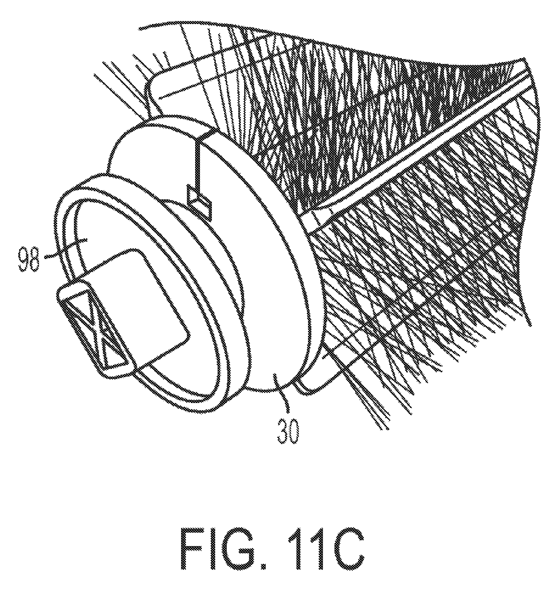
D00013

D00014
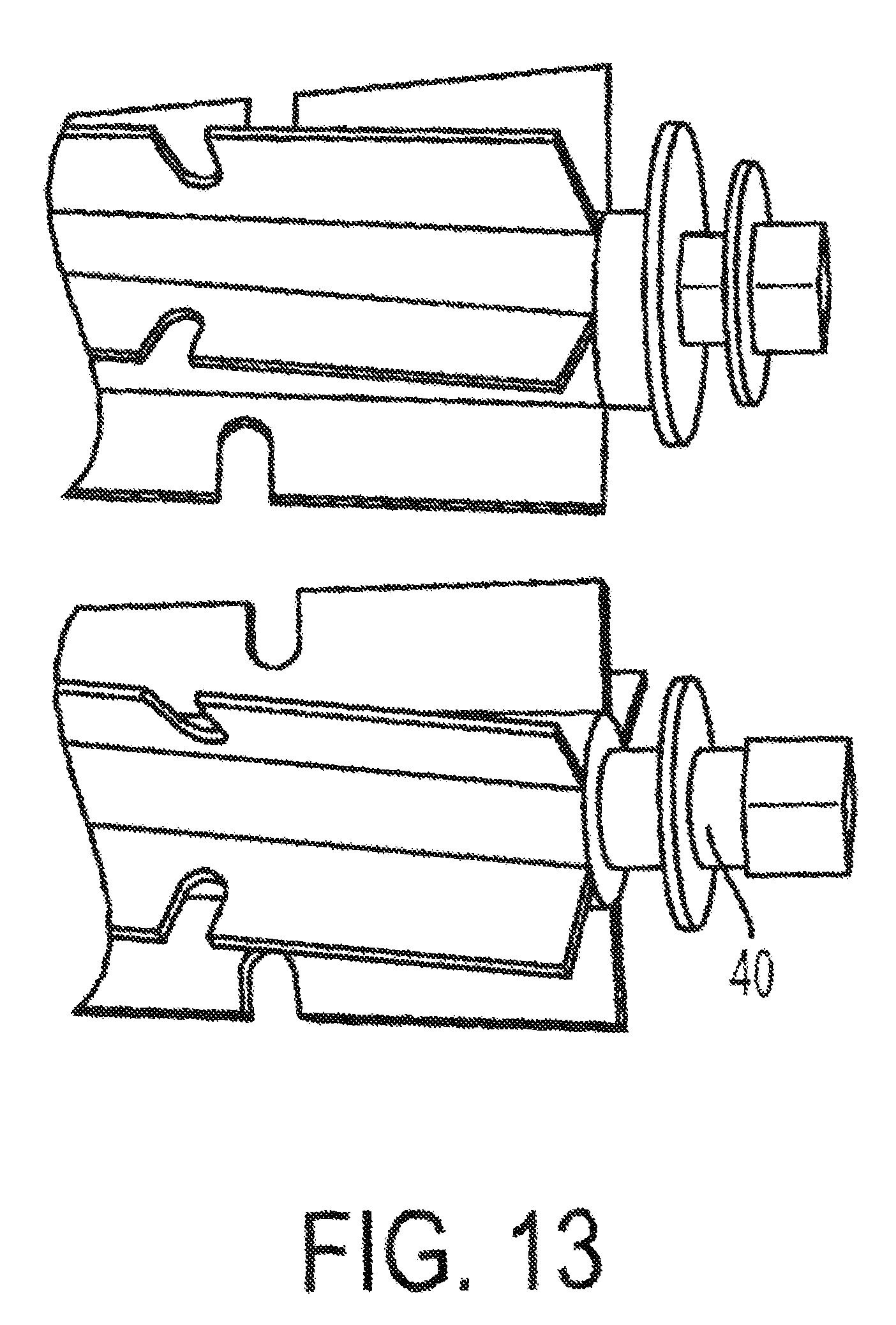
D00015
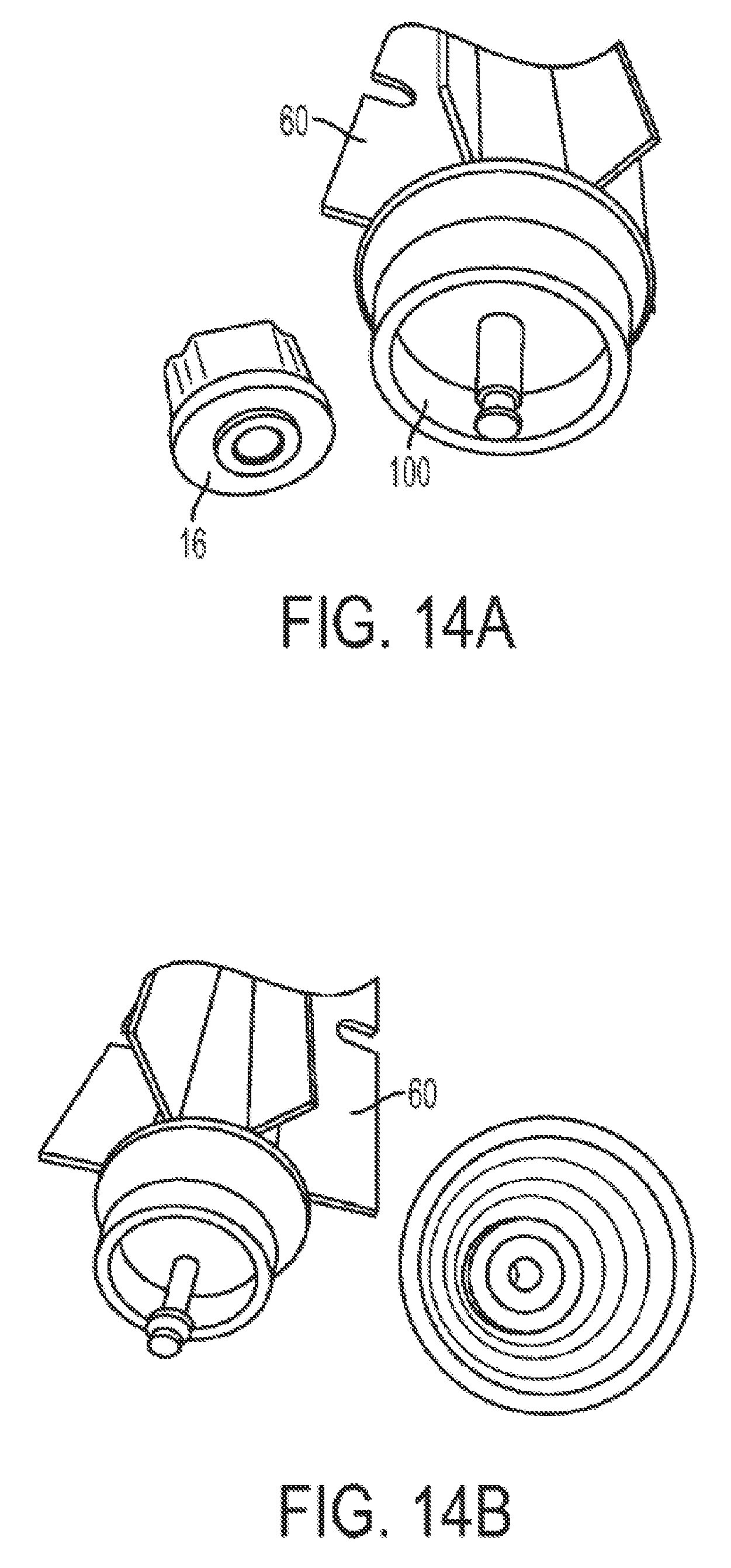
D00016

D00017

D00018
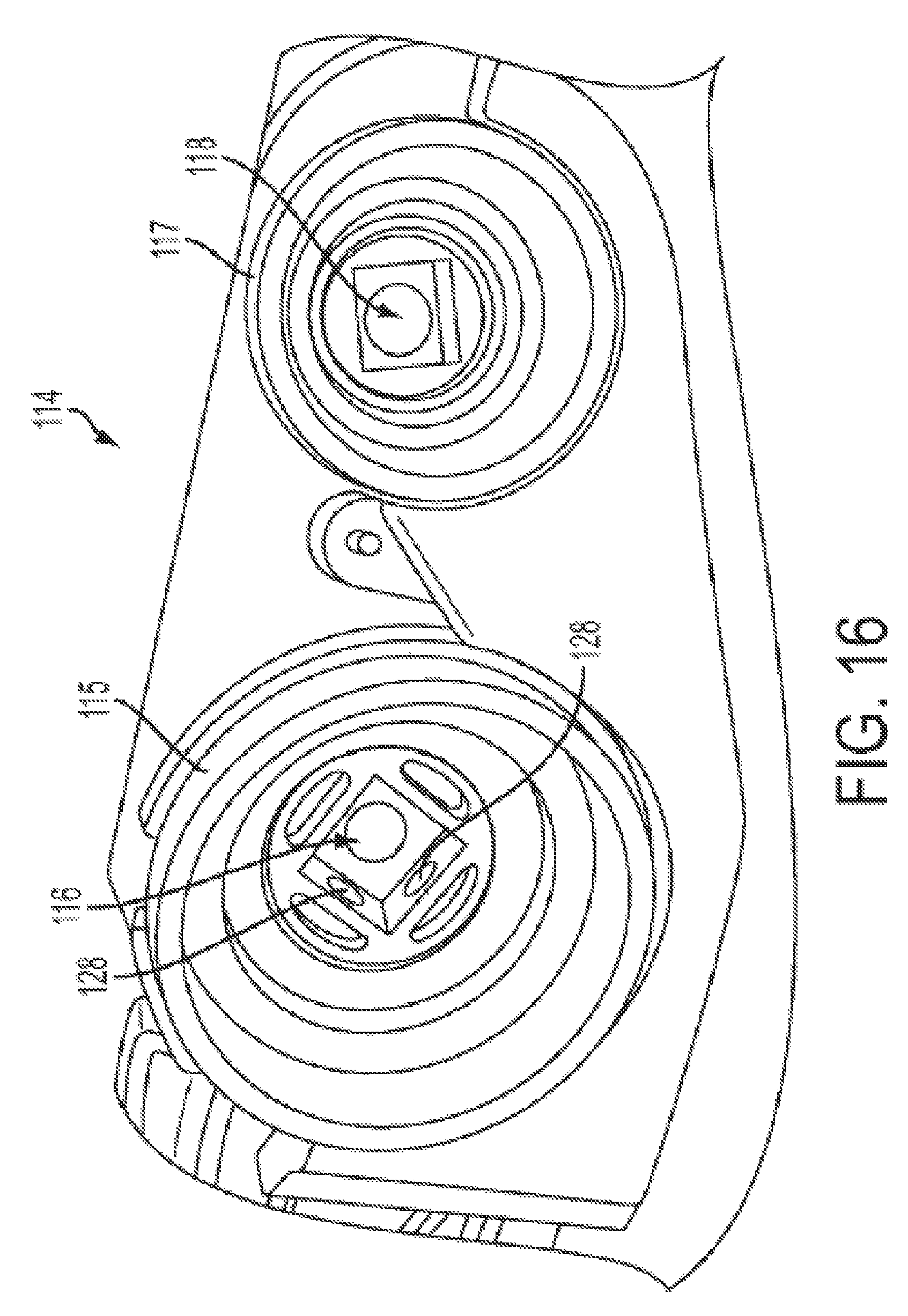
D00019

D00020

D00021

D00022
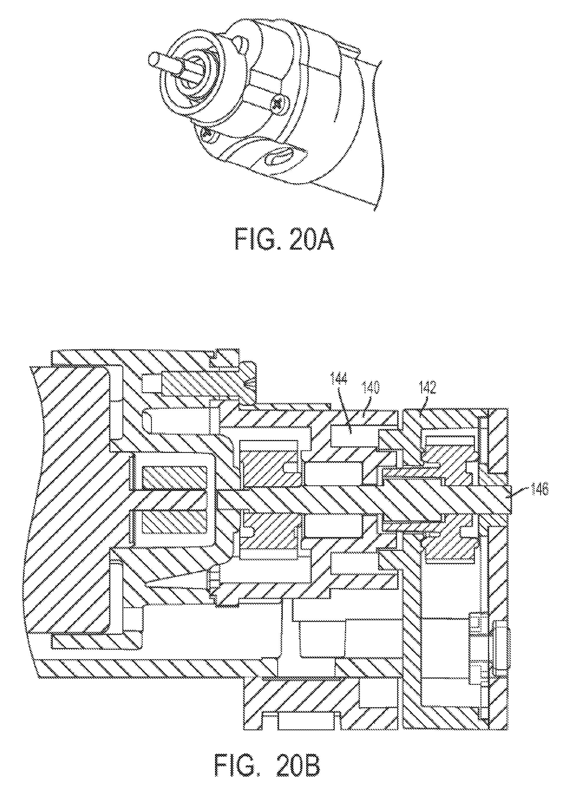
D00023

XML
uspto.report is an independent third-party trademark research tool that is not affiliated, endorsed, or sponsored by the United States Patent and Trademark Office (USPTO) or any other governmental organization. The information provided by uspto.report is based on publicly available data at the time of writing and is intended for informational purposes only.
While we strive to provide accurate and up-to-date information, we do not guarantee the accuracy, completeness, reliability, or suitability of the information displayed on this site. The use of this site is at your own risk. Any reliance you place on such information is therefore strictly at your own risk.
All official trademark data, including owner information, should be verified by visiting the official USPTO website at www.uspto.gov. This site is not intended to replace professional legal advice and should not be used as a substitute for consulting with a legal professional who is knowledgeable about trademark law.