Universal conduit liner for a welding torch
Kinder , et al.
U.S. patent number 10,300,550 [Application Number 13/746,801] was granted by the patent office on 2019-05-28 for universal conduit liner for a welding torch. This patent grant is currently assigned to Victor Equipment Company. The grantee listed for this patent is Victor Equipment Company. Invention is credited to David Allen Kinder, Kyle Stuart, Bryan Young.


| United States Patent | 10,300,550 |
| Kinder , et al. | May 28, 2019 |
Universal conduit liner for a welding torch
Abstract
A universal conduit assembly for a welding torch is provided that includes a conduit liner defining a proximal end portion and a distal end portion, a conduit tip secured to the proximal end portion of the conduit liner, and an interchangeable conduit stop removably secured to the conduit tip. The interchangeable conduit stop is adapted for connection to a specific OEM (Original Equipment Manufacturer) power connector.
| Inventors: | Kinder; David Allen (Lewisville, TX), Young; Bryan (Luling, TX), Stuart; Kyle (Wichita, KS) | ||||||||||
|---|---|---|---|---|---|---|---|---|---|---|---|
| Applicant: |
|
||||||||||
| Assignee: | Victor Equipment Company
(Denton, TX) |
||||||||||
| Family ID: | 47710318 | ||||||||||
| Appl. No.: | 13/746,801 | ||||||||||
| Filed: | January 22, 2013 |
Prior Publication Data
| Document Identifier | Publication Date | |
|---|---|---|
| US 20130240496 A1 | Sep 19, 2013 | |
Related U.S. Patent Documents
| Application Number | Filing Date | Patent Number | Issue Date | ||
|---|---|---|---|---|---|
| 61588592 | Jan 19, 2012 | ||||
| Current U.S. Class: | 1/1 |
| Current CPC Class: | B23K 9/24 (20130101); B23K 9/323 (20130101) |
| Current International Class: | B23K 9/24 (20060101); B23K 9/32 (20060101) |
| Field of Search: | ;219/138 |
References Cited [Referenced By]
U.S. Patent Documents
| 2727970 | December 1955 | Turbett |
| 3248515 | April 1966 | Gorman et al. |
| 3249734 | May 1966 | Meyer |
| 3261962 | July 1966 | Carkhuff et al. |
| 3272961 | September 1966 | Maier, Jr. et al. |
| 3281571 | October 1966 | Gilmore |
| 3283833 | November 1966 | Bodine, Jr. |
| 3444352 | May 1969 | Ogden et al. |
| 3783233 | January 1974 | dal Molin |
| 3891249 | June 1975 | Moore |
| 3980860 | September 1976 | Howell et al. |
| 3999033 | December 1976 | Willgohs et al. |
| 4105891 | August 1978 | Hill et al. |
| 4158763 | June 1979 | Moerke |
| 4206862 | June 1980 | DaCosta |
| 4282419 | August 1981 | Auer |
| 4284873 | August 1981 | Schluter |
| 4393298 | July 1983 | Frantzreb, Sr. |
| 4582979 | April 1986 | Moerke |
| 4600824 | July 1986 | Moerke |
| 4624410 | November 1986 | Rogers |
| 4687899 | August 1987 | Acheson |
| 4873419 | October 1989 | Acheson |
| 4879446 | November 1989 | Morgan et al. |
| 4892990 | January 1990 | Acheson |
| 4952769 | August 1990 | Acheson |
| 5384447 | January 1995 | Raloff et al. |
| 5521355 | May 1996 | Lorentzen |
| 5558268 | September 1996 | Acheson |
| 5595671 | January 1997 | David |
| 5728995 | March 1998 | Kensrue |
| 5782987 | July 1998 | Furman |
| 6054675 | April 2000 | Kurokawa et al. |
| 6062386 | May 2000 | Inoue et al. |
| 6066823 | May 2000 | Lageose |
| 6079243 | June 2000 | Inoue et al. |
| 6137076 | October 2000 | Esslinger et al. |
| RE36997 | December 2000 | Kensrue |
| 6284995 | September 2001 | Esslinger et al. |
| 6337144 | January 2002 | Shimizu et al. |
| 6486438 | November 2002 | Esslinger |
| 6649858 | November 2003 | Wakeman |
| 6747248 | June 2004 | Hoffmann |
| 6786752 | September 2004 | Kerekes et al. |
| 7274001 | September 2007 | Cusick, III |
| 7309844 | December 2007 | Lajoie |
| 7381923 | June 2008 | Gordon et al. |
| 8106327 | January 2012 | Scaini et al. |
| 8389899 | March 2013 | Natta |
| 8552341 | October 2013 | Zamuner |
| 8686317 | April 2014 | Centner |
| 8907249 | December 2014 | Berger et al. |
| 2002/0005397 | January 2002 | Bong et al. |
| 2002/0158048 | October 2002 | Stricklen |
| 2003/0015511 | January 2003 | Kim et al. |
| 2003/0085211 | May 2003 | Ito et al. |
| 2005/0044687 | March 2005 | Matsuguchi et al. |
| 2005/0045699 | March 2005 | Konishi et al. |
| 2005/0072764 | April 2005 | Lajoie |
| 2005/0133486 | June 2005 | Baker et al. |
| 2005/0150883 | July 2005 | Tomiyasu et al. |
| 2005/0189333 | September 2005 | Nakagiri et al. |
| 2005/0211686 | September 2005 | Inoue et al. |
| 2005/0218132 | October 2005 | Wells |
| 2006/0000817 | January 2006 | Inoue et al. |
| 2007/0164008 | July 2007 | Koshiishi et al. |
| 2008/0056859 | March 2008 | Inoue et al. |
| 2008/0204072 | August 2008 | Sasao et al. |
| 2008/0236324 | October 2008 | Inoue et al. |
| 2008/0257868 | October 2008 | Sassatelli et al. |
| 2008/0314876 | December 2008 | Pinsonneault et al. |
| 2010/0032420 | February 2010 | Inoue et al. |
| 2010/0108656 | May 2010 | Natta |
| 2010/0276407 | November 2010 | Cooper |
| 2011/0024394 | February 2011 | Esslinger |
| 2012/0125904 | May 2012 | Lee et al. |
| 198 13 419 | Nov 1998 | DE | |||
| 202010007364 | Aug 2010 | DE | |||
| WO 2010/135752 | Dec 2010 | WO | |||
Other References
|
PCT Serial No. PCT/US2013/022509--International Search Report and the Written Opinion of the International Searching Authority, dated Apr. 26, 2013. cited by applicant . Communication pursuant to Article 94(3) EPC for European Patent Application No. 13703938.4, dated Jul. 4, 2018, 5 pages. cited by applicant. |
Primary Examiner: Stapleton; Eric S
Attorney, Agent or Firm: Edell, Shapiro & Finnan, LLC
Parent Case Text
CROSS-REFERENCE TO RELATED APPLICATIONS
This application claims the benefit of provisional application Ser. No. 61/588,592, filed on Jan. 19, 2012. The disclosure of the above application is incorporated herein by reference.
Claims
What is claimed is:
1. A universal conduit assembly for a welding torch comprising: a conduit liner defining a proximal end portion and a distal end portion; a conduit tip secured to the proximal end portion of the conduit liner; and an interchangeable conduit stop removably secured to the conduit tip, the interchangeable conduit stop adapted for connection to a specific OEM power connector, wherein the interchangeable conduit stop extends beyond a distal end of the conduit tip to partially cover an electrical insulator surrounding and positioned directly adjacent to the conduit liner.
2. The universal conduit assembly according to claim 1, wherein the conduit tip defines a central bore extending from a proximal end portion to a distal end portion, and a chamfer disposed around the central bore at the distal end portion.
3. The universal conduit assembly according to claim 1, wherein a proximal end portion of the conduit tip extends to the distal end portion of the conduit stop, to the proximal end portion of the conduit stop, or beyond the proximal end portion of the conduit stop.
4. The universal conduit assembly according to claim 1, wherein the conduit tip defines an internal shoulder, and the proximal end portion of the conduit liner abuts the internal shoulder of the conduit tip.
5. The universal conduit assembly according to claim 1, wherein the conduit tip defines an external attachment area, and the interchangeable conduit stop is removably secured to the external attachment area of the conduit tip.
6. The universal conduit assembly according to claim 5, wherein the external attachment area is selected from the group consisting of threads, taper lock, and a set screw.
7. The universal conduit assembly according to claim 6, wherein the interchangeable conduit stop defines an internally threaded portion for engagement with the externally threaded portion of the conduit tip.
8. The universal conduit assembly according to claim 1, wherein the conduit stop comprises an external surface for engagement of the specific OEM power connector.
9. The universal conduit assembly according to claim 1 further comprising a sealing element disposed around an external portion of the conduit stop.
10. The universal conduit assembly according to claim 1, wherein the conduit tip is secured to the conduit liner by one selected from the group of crimping, press-fitting, and adhesive bonding.
11. The universal conduit assembly according to claim 1, wherein the conduit stop defines an internal shoulder and the conduit tip defines an external shoulder such that the external shoulder of the conduit tip abuts the internal shoulder of the conduit stop.
12. A welding torch comprising: a welding gun handle; a welding cable defining a proximal end portion and a distal end portion, the welding cable secured to the welding gun handle at the distal end portion; a universal conduit assembly disposed at the proximal end portion of the welding cable, the universal conduit assembly comprising: a conduit liner included as part of the welding cable and further defining the proximal end portion and distal end portion; a conduit tip secured to the proximal end portion of the conduit liner; and an interchangeable conduit stop removably secured to the conduit tip, the interchangeable conduit stop adapted for connection to a specific OEM power connector, wherein the interchangeable conduit stop extends beyond a distal end of the conduit tip to partially cover an electrical insulator surrounding and positioned directly adjacent to the conduit liner.
13. The welding torch according to claim 12, wherein a proximal end portion of the conduit tip extends to a distal end portion of the conduit stop.
14. The welding torch according to claim 12, wherein the conduit tip defines an external attachment area, and the interchangeable conduit stop is secured to the external attachment area of the conduit tip.
15. The welding torch according to claim 12, wherein the external attachment area is selected from the group consisting of threads, taper lock, and a set screw.
16. The welding torch according to claim 15, wherein the interchangeable conduit stop defines an internally threaded portion for engagement with the externally threaded portion of the conduit tip.
17. The welding torch according to claim 12, wherein the conduit stop defines an internal shoulder and the conduit tip defines an external shoulder such that the external shoulder of the conduit tip abuts the internal shoulder of the conduit stop to provide a gas seal.
18. A welding conduit kit comprising: a conduit liner defining a proximal end portion and a distal end portion; a conduit tip secured to the proximal end portion of the conduit liner; and a plurality of interchangeable conduit stops adapted for being removably secured to the conduit tip, the interchangeable conduit stops adapted for connection to specific OEM power connectors, wherein the interchangeable conduit stops extend beyond a distal end of the conduit tip to partially cover an electrical insulator surrounding and positioned directly adjacent to the conduit liner.
19. The welding conduit kit according to claim 18, wherein the conduit tip defines an external attachment area, and the interchangeable conduit stops are secured to the external attachment area of the conduit tip.
20. The welding conduit kit according to claim 19, wherein the external attachment area is selected from the group consisting of threads, taper lock, and a set screw.
21. The welding conduit kit according to claim 20, wherein the interchangeable conduit stop defines an internally threaded portion for engagement with the externally threaded portion of the conduit tip.
22. A universal conduit assembly for a welding torch comprising: a conduit liner defining a proximal end portion and a distal end portion; a conduit tip secured around the proximal end portion of the conduit liner, the conduit tip defining an externally threaded portion, a central bore extending from a proximal end portion to a distal end portion, and a chamfer disposed around the central bore at the distal end portion; and an interchangeable conduit stop defining an internally threaded portion for engagement with the externally threaded portion of the conduit tip, the interchangeable conduit stop adapted for connection to a specific OEM power connector, wherein the interchangeable conduit stop extends beyond a distal end of the conduit tip to partially cover an electrical insulator surrounding and positioned directly adjacent to the conduit liner, and wherein the proximal end portion of the conduit tip extends to a distal end portion of the conduit stop, and the conduit stop defines an internal shoulder and the conduit tip defines an external shoulder such that the external shoulder of the conduit tip abuts the internal shoulder of the conduit stop to provide a gas seal.
23. A conduit tip for use with a conduit liner of a welding torch, the conduit tip comprising: a body defining a proximal end portion and a distal end portion; an external attachment area for securing a variety of conduit stops; an internal recess for receiving a conduit liner; a central bore extending from the proximal end portion to the distal end portion; a chamfer disposed around the central bore at the proximal end portion; and an external shoulder adapted for engaging an internal shoulder of one of the variety of conduit stops to provide a gas seal, the one of the variety of conduit stops extending beyond a distal end of the conduit tip to partially cover an electrical insulator surrounding and positioned directly adjacent to the conduit liner.
24. The conduit tip according to claim 23, wherein the external attachment area is selected from the group consisting of threads, taper lock, and a set screw.
Description
FIELD
The disclosure relates generally to arc welding torch systems and components used in arc welding torches. More specifically, the disclosure relates to a universal conduit assembly applicable to gas metal arc welding (GMAW) or metal inert gas (MIG) welding systems.
BACKGROUND
The statements in this section merely provide background information related to the present disclosure and may not constitute prior art.
Gas metal arc welding (GMAW) or metal inert gas (MIG) welding utilize a metal wire to act as the electrode to produce an arc. The wire, which is shielded by an inert gas, acts a filler or raw material that forms the weld. Typically, the wire and gas are fed through a welding gun positioned proximate to the desired location for the weld. The wire is fed to the gun through a conduit coupled to both a powered wire feeder and a gas flow regulation system.
Traditionally, conduits consist of a coiled steel liner used to guide the welding wire and a brass connector that is crimped over the end of the conduit. The connector is designed to reversibly couple with the rear power plug of a torch or welding gun. The specific design of the connector is dependent upon the manufacturer of the welding gun because different manufacturers will differentiate their gun design from competitive products by using different plug geometries.
The different plug geometries utilized on different welding gun designs requires equipment distributors to stock a variety of conduits each having different end connectors in order to accommodate the various gun designs. For small distributors, the necessity of carrying a full line of conduits for each different welding gun is not economically feasible. In addition, end users of welding guns may use guns made by different manufacturers and are then limited to selecting a large distributor that can stock a full line of conduits for each welding gun or to use multiple distributors to service their equipment. In either case, the end-user is required to purchase and stock multiple conduit lines to service the various welding guns that they own.
DRAWINGS
The drawings described herein are for illustration purposes only and are not intended to limit the scope of the present disclosure in any way.
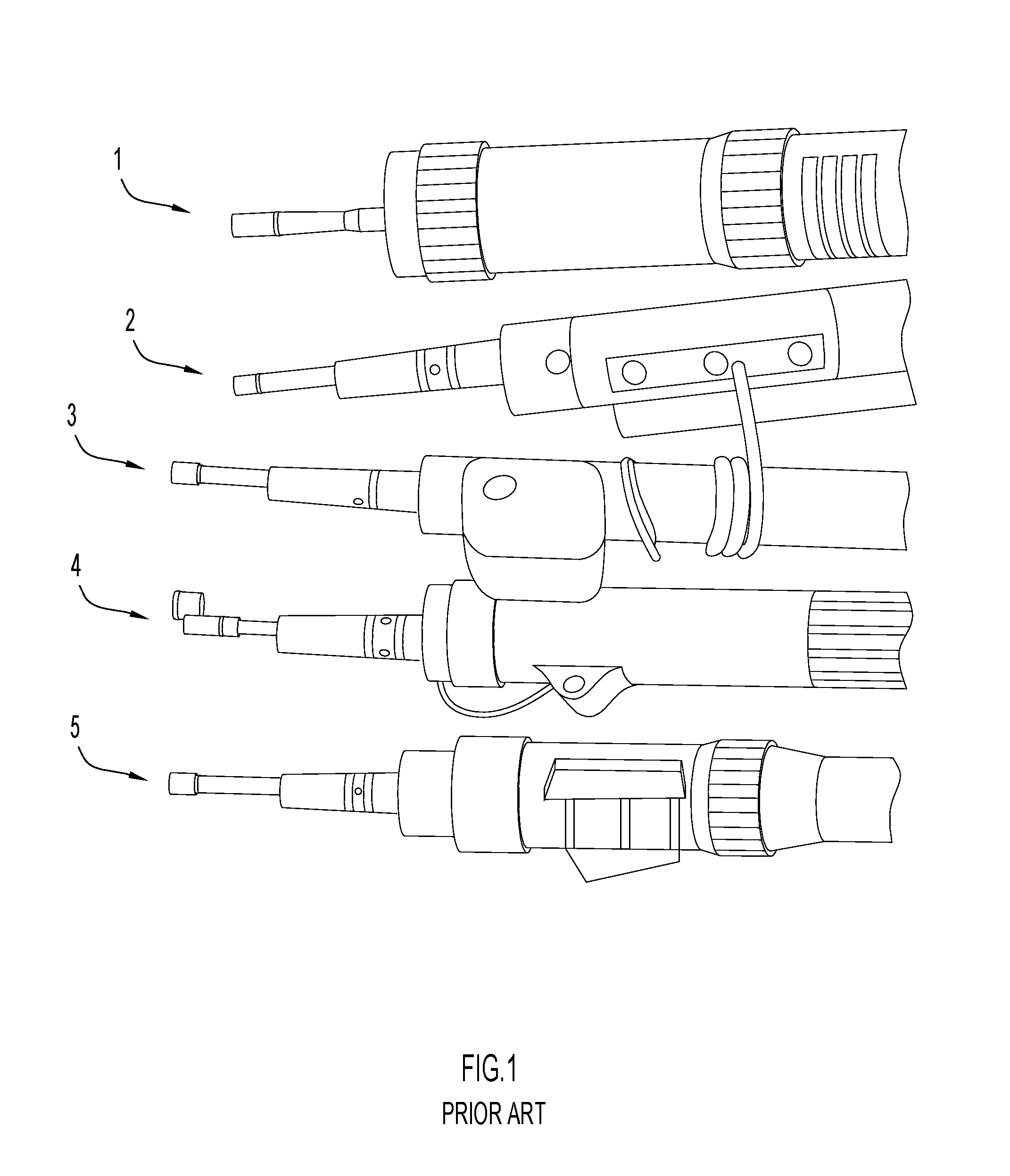
FIG. 1 is a perspective view of conventional conduit connector geometries used by five welding gun manufacturers;
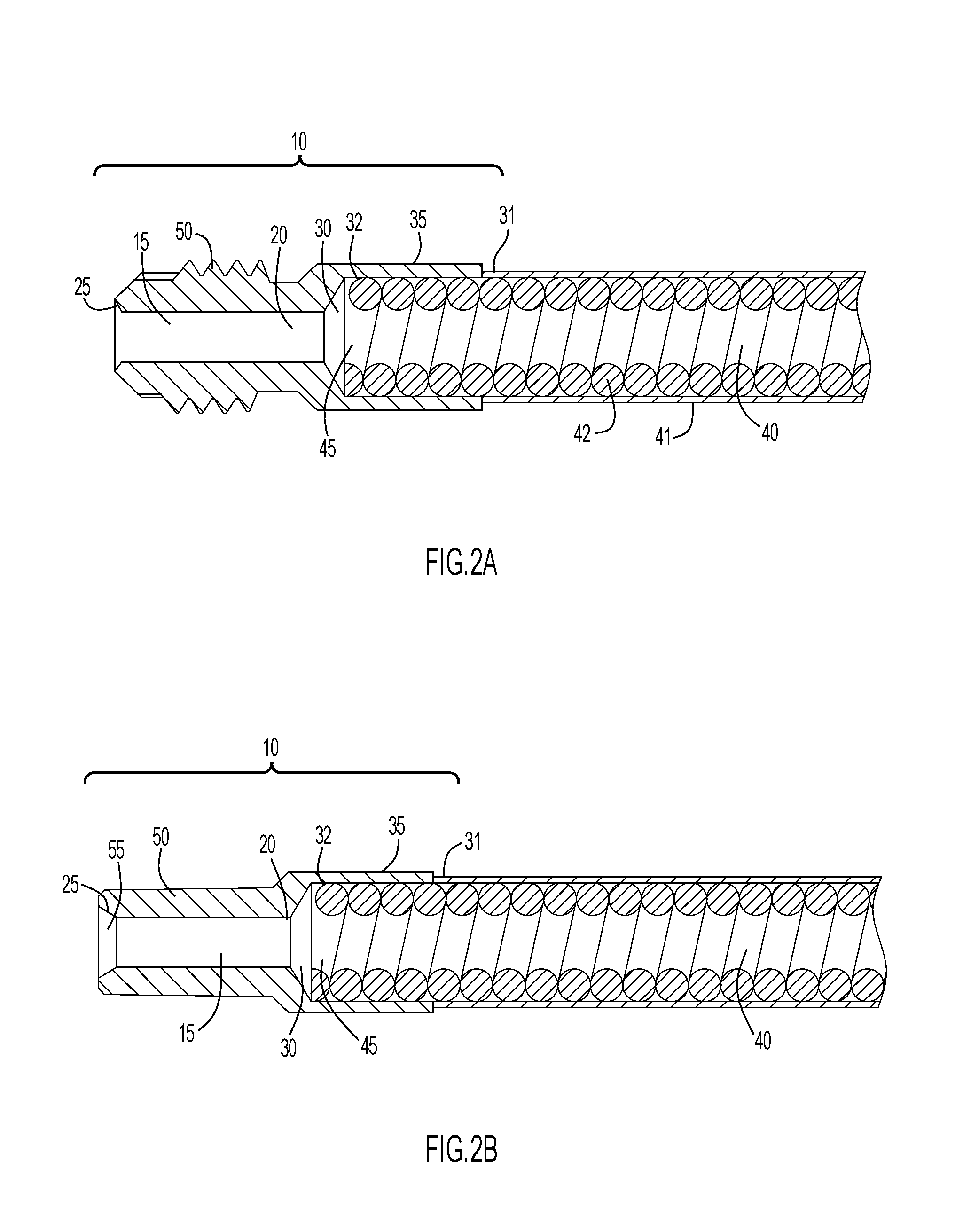
FIG. 2A is a cross-sectional view of a conduit tip and conduit liner prepared according to the teachings of the present disclosure;
FIG. 2B is a cross-sectional view of a conduit tip and conduit liner according to another aspect of the present disclosure;
FIG. 3A is a cross-sectional view of a universal conduit assembly according to the teachings of the present disclosure showing a conduit stop coupled with the conduit tip and liner of FIG. 2A;
FIG. 3B is a cross-sectional view of another universal conduit assembly according to another aspect of the present disclosure showing a conduit stop coupled with the conduit tip and liner of FIG. 2B;
FIG. 3C is a cross-sectional view of a universal conduit assembly according to another aspect of the present disclosure showing a conduit stop coupled with the conduit tip and liner of FIG. 2C;
FIG. 4 is a cross-sectional view of a universal conduit assembly according to yet another aspect of the present disclosure;
FIG. 5A is a perspective view comparing the geometric similarity between (1) a conventional conduit connector from a first manufacturer and (2) a universal conduit assembly prepared according to the teachings of the present disclosure;
FIG. 5B is a perspective view comparing the geometric similarity between (1) a conventional conduit connector from a second manufacturer and (2) a universal conduit assembly prepared according to the teachings of the present disclosure;
FIG. 5C is a perspective view comparing the geometric similarity between (1) a conventional conduit connector from a third manufacturer and (2) a universal conduit assembly prepared according to the teachings of the present disclosure;
FIG. 5D is a perspective view comparing the geometric similarity between (1) a conventional conduit connector from a fourth manufacturer and (2) a universal conduit assembly prepared according to the teachings of the present disclosure;
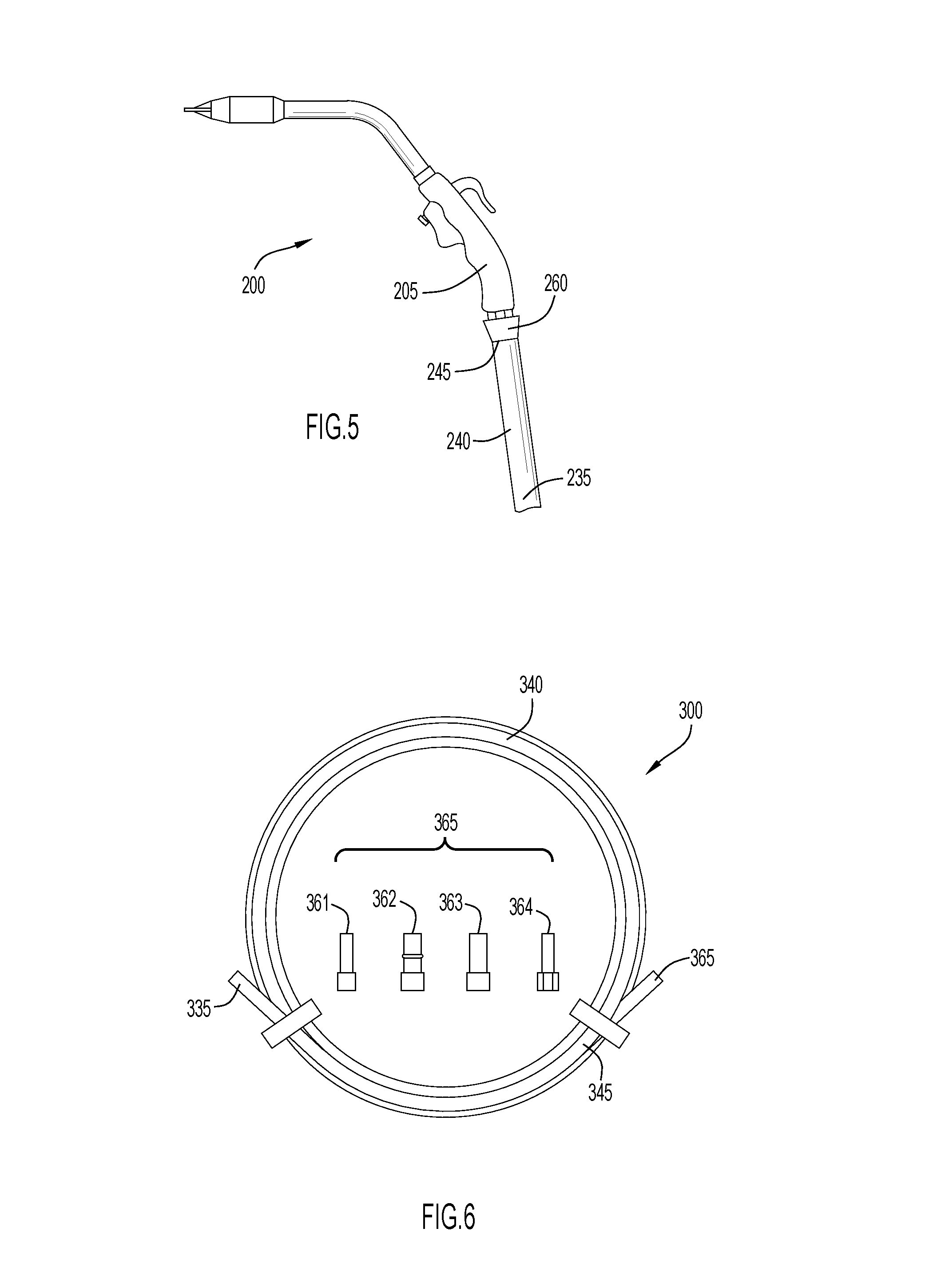
FIG. 6 is a perspective view of a welding conduit kit prepared according to the teachings of the present disclosure;
FIG. 7A is a perspective view comparing the geometric similarity between (1) a universal conduit assembly prepared according to the teachings of the present disclosure and (2) a conventional conduit connector from a first manufacturer;
FIG. 7B is a perspective view comparing the geometric similarity between (1) a universal conduit assembly prepared according to the teachings of the present disclosure and (2) a conventional conduit connector from a second manufacturer;
FIG. 7C is a perspective view comparing the geometric similarity between (1) a universal conduit assembly prepared according to the teachings of the present disclosure and (2) a conventional conduit connector from a third manufacturer; and
FIG. 7D is a perspective view comparing the geometric similarity between (1) a universal conduit assembly prepared according to the teachings of the present disclosure and (2) a conventional conduit connector from a fourth manufacturer.
DETAILED DESCRIPTION
The following description is merely exemplary in nature and is in no way intended to limit the present disclosure or its application or uses. It should be understood that throughout the description and drawings, corresponding reference numerals indicate like or corresponding parts and features. As used throughout the description and claims, the term "proximal" refers to a position that is located towards the torch or gun handle, while the term "distal" refers to a position that is located towards the electrical power supply.
The present disclosure generally provides a universal conduit assembly for a welding torch comprising a conduit liner defining a proximal end portion and a distal end portion; a conduit tip secured to the proximal end portion of the conduit liner; and an interchangeable conduit stop reversibly secured to the conduit tip. The interchangeable conduit stop is adapted for connection to a specific OEM (Original Equipment Manufacturer) power connector. For example, interchangeable conduit stops of the present disclosure are designed to resemble the conventional connector geometries used by different manufacturers, for example, as shown in FIG. 1.
Referring to FIG. 2A, the conduit tip 10 defines a central bore 15 extending from a proximal end portion 25 to a distal end portion 20, and a chamfer 30 disposed around the central bore 15 at the distal end portion 20. The conduit tip 10 defines an internal shoulder 35 having a first end 31 and a second end 32. The internal shoulder 35 is open at the first end 31, while the second end 32 engages the chamfer 30.
A conduit liner 40 having a proximal end portion 45 and a distal end portion engages the internal shoulder 35 where the proximal end portion 45 of the conduit liner 40 abuts the second end 32 of the internal shoulder 35 and the chamfer 30. The presence of the chamfer 30 provides protection for the conduit liner 40 against the presence of any sharp edges existing at the distal end portion 20 of the conduit tip 10. The conduit tip 10 is sized in order for the internal shoulder 35 to accommodate the outer diameter of the conduit liner 40. The conduit liner 40 can be any type of conduit known to one skilled in the art of welding. The conduit liner 40 may include a polymer material 41, such as a shrink tubing material, disposed about a metal coiled conduit 42. The conduit tip 10 can be secured to the conduit liner 40 by any method known to one skilled in the art, including but not limited to crimping, press-fitting, and adhesive bonding.
The conduit tip 10 further defines an external attachment area 50, which may be threaded as shown in FIG. 2A. A conduit tip 10 according to another aspect of the present disclosure is shown in FIG. 2B, where the external attachment area 50 is tapered, instead of being threaded. The angle of the taper is preferably about 1.5 degrees although one skilled-in-the-art will recognize that other taper angles may be used. Referring to FIG. 2B, the proximal end portion 25 of the conduit tip 10 may also include a chamfer 55 that encompasses the central bore 15. The purpose of the external attachment area 50 is to allow the conduit tip 10 to engage and become reversibly secured to a conduit stop. The means of attachment of the conduit tip 10 to a conduit stop is preferably one selected from the group of the meshing of threads, a taper lock, and a set screw. Preferably, the means of attachment is through the use of threads or a set screw because the use of a taper connection sometimes makes the disassembly of the parts more difficult due to the strength of the interaction between the conduit tip 15 and conduit stop. The body of the conduit stop defines an internally threaded portion for engagement with the externally threaded portion of the conduit tip. In order to reduce the occurrence of burrs when a threaded external attachment area 50 is used, the threads may comprise about a 30 degree angle at the start and the end of the threads.
Referring now to FIGS. 3A and 3B, a universal conduit assembly 60 made according to the teachings of the present disclosure is shown. The universal conduit assembly 60 comprises a conduit stop 65, as well as the conduit tip 10 and conduit liner 40 as previously described with respect to FIGS. 2A and 2B. The conduit stop 65 and the conduit tip 10 engage one anther via the attachment area of the conduit tip 10. Preferably, the proximal end portion 25 of the conduit tip 10 extends to and engages the proximal end portion 70 of the conduit stop 65. One skilled-in-the-art will recognize that the distal end portion 25 of the conduit tip 10 may extend past or beyond the proximal end portion 70 of the conduit stop 65 as shown in FIG. 3C, where the distal end portion 25 of the conduit tip 15 extends to the distal end portion 75 of the conduit stop 65.
Referring again to FIGS. 3A and 3B, the conduit stop 65 defines an internal shoulder 80 and the conduit tip 10 defines an external shoulder 85 such that the external shoulder 85 of the conduit tip 10 abuts the internal shoulder 80 of the conduit stop 65 to provide a metal-to-metal gas seal. The internal shoulder 80 may also provide for the proper positioning of the conduit tip 15 in order for engagement with the conduit stop 65 through its attachment area 50. Referring now to FIG. 3C, the metal-to-metal gas seal may also be established by an angled shoulder 100 made by an indentation established in the body of the conduit stop 65 and a corresponding abutment established in the body of the conduit tip 15. The angle of the angled shoulder 100 is preferably about 118 degrees, although one skilled-in-the-art will recognize that other angles could be used.
Referring now to FIG. 4, a universal conduit assembly 60 prepared according to another aspect of the present disclosure is presented. In this case, the conduit liner 40 extends all the way to the distal end portion 75 of the conduit stop 65. A set screw 105 is used to secure the conduit stop 65 to the conduit liner 40. In this case, the presence of a conduit tip 15 is not necessary.
The external shape of the conduit stop 65 is designed to substantially resemble a specific OEM power connector for use with a corresponding welding torch system. The conduit stop 65 comprises an external surface 87 that may engage the specific OEM power connector. The specific OEM power connector is preferably selected from the group consisting of BERNARD.TM., MILLER.RTM., TREGASKISS.TM., and TWECO.RTM. connectors. When desired or necessitated by the OEM power connector design, the universal conduit assembly 60 may include a sealing element 90 disposed around an external surface 87 of the conduit stop 65. The conduit stop 65 may also optionally comprise a chamfer 95 at its distal end 75 in order to protect the welding wire from any sharp edges.
The conduit liner 40 may comprise a polymer material 41 disposed around a metal coil or braided conduit 42. The metal coil conduit 42 may be comprised of a metal, such as, for example, aluminum, steel, copper, or a metal alloy, such as, for example, brass. The polymer material 41 may include, but not be limited to, any polymer that can provide electrical insulation and exhibit high thermal stability. Such a polymer material 41 is preferably available as a form of shrink wrap tubing. Similarly, the conduit tip 15 and conduit stop 65 may be formed from a metal that exhibits good electrical conductivity. Examples of such metals include aluminum, brass, and copper.
The conduit tip 15, conduit liner 40, and conduit stop 65 are each sized to accommodate the diameter size of the desired welding wire electrode selected for use. A different conduit tip 15, conduit liner 40, and conduit stop 65 may be required for each different wire size that may be used.
Referring now to FIG. 5, it is another objective of the present disclosure to provide a welding torch assembly 200 that comprises a welding gun handle 205; a welding cable 240 defining a proximal end portion 245 and a distal end portion 235, the welding cable 240 secured to the welding gun handle 205 at the proximal end portion 245; and a conduit assembly 260 disposed at the proximal end portion 245 of the welding cable 240. The conduit assembly 260 used for this welding torch assembly 200 is the universal conduit assembly 60 made by the teachings of the present disclosure. In such this conduit assembly 60 comprises a conduit liner 40 defining a proximal end portion 45 and a distal end portion; a conduit tip 15 secured to the proximal end portion 45 of the conduit liner 40; and an interchangeable conduit stop 65 removably secured to the conduit tip 15 with the interchangeable conduit stop 65 adapted for connection to a specific OEM power connector. The OEM power connector is typically part of the welding gun handle 205.
Referring now to FIG. 6, it is yet another objective of the present disclosure to provide a welding conduit kit 300 that comprises a conduit liner 340 defining a proximal end portion 345 and a distal end portion 335; a conduit tip 315 secured to the proximal end portion 345 of the conduit liner 340; and a plurality of interchangeable conduit stops 365 adapted for being removably secured to the conduit tip 315, the interchangeable conduit stops 365 adapted for connection to specific OEM power connectors. The specific OEM power connector is preferably selected from the group consisting of TWECO.RTM. 361, BERNARD.TM. 362, MILLER.RTM. 363, and TREGASKISS.TM. 364.
The following specific examples are given to illustrate the invention and should not be construed to limit the scope of the invention.
EXAMPLE 1
Comparison Between Universal Conduit Assembly and Specific OEM Power Connector
Universal conduit assemblies 60 were prepared according to the teachings of the present disclosure to resemble the OEM power connectors manufactured by TREGASKISS.TM., BERNARD.TM., TWECO.RTM., and MILLER.RTM.. These universal conduit assemblies 60 were connected to a corresponding welding torch and found to perform similarly to conventional OEM power connectors. A visual comparison between the universal adapter assemblies 60 and the corresponding OEM power connectors are provided in FIG. 7. More specifically, the universal adapter assemblies 60 of the present disclosure are labeled as trial #1. while the specific OEM power connector sold by TREGASKISS.TM. (FIG. 7A), BERNARD.TM. (FIG. 7B), TWECO .TM. (FIG. 7C), and MILLER.RTM. (FIG. 7D) are labeled as trial #2.
FIG. 7A is a perspective view comparing the geometric similarity between (1) a universal conduit assembly prepared according to the teachings of the present disclosure and (2) a conventional conduit connector manufactured by Tregaskiss.TM.. FIG. 7B is a perspective view comparing the geometric similarity between (1) a universal conduit assembly prepared according to the teachings of the present disclosure and (2) a conventional conduit connector manufactured by Bernard.TM.. FIG. 7C is a perspective view comparing the geometric similarity between (1) a universal conduit assembly prepared according to the teachings of the present disclosure and (2) a conventional conduit connector manufactured by Tweco.RTM.. FIG. 7D is a perspective view comparing the geometric similarity between (1) a universal conduit assembly prepared according to the teachings of the present disclosure and (2) a conventional conduit connector manufactured by Miller.RTM.. It should be noted that the disclosure is not limited to the embodiment described and illustrated as examples. A large variety of modifications have been described and more are part of the knowledge of the person skilled in the art. These and further modifications as well as any replacement by technical equivalents may be added to the description and figures, without leaving the scope of the protection of the disclosure and of the present patent. Further description of the present disclosure is provided in the notebook pages provided as Attachment A and incorporated herein, in its entirety, by reference.
* * * * *
D00000
D00001
D00002
D00003
D00004
D00005
XML
uspto.report is an independent third-party trademark research tool that is not affiliated, endorsed, or sponsored by the United States Patent and Trademark Office (USPTO) or any other governmental organization. The information provided by uspto.report is based on publicly available data at the time of writing and is intended for informational purposes only.
While we strive to provide accurate and up-to-date information, we do not guarantee the accuracy, completeness, reliability, or suitability of the information displayed on this site. The use of this site is at your own risk. Any reliance you place on such information is therefore strictly at your own risk.
All official trademark data, including owner information, should be verified by visiting the official USPTO website at www.uspto.gov. This site is not intended to replace professional legal advice and should not be used as a substitute for consulting with a legal professional who is knowledgeable about trademark law.