Atomizer for a personal vaporizing unit
Terry , et al.
U.S. patent number 10,300,225 [Application Number 15/981,303] was granted by the patent office on 2019-05-28 for atomizer for a personal vaporizing unit. This patent grant is currently assigned to RAI Strategic Holdings, Inc.. The grantee listed for this patent is RAI Strategic Holdings, Inc.. Invention is credited to Noah Mark Minskoff, Nathan Andrew Terry.


View All Diagrams
| United States Patent | 10,300,225 |
| Terry , et al. | May 28, 2019 |
Atomizer for a personal vaporizing unit
Abstract
A personal vapor inhaling unit is disclosed. An electronic flameless vapor inhaler unit that may simulate a cigarette has a cavity that receives a cartridge in the distal end of the inhaler unit. The cartridge brings a substance to be vaporized in contact with a wick. When the unit is activated, and the user provides suction, the substance to be vaporized is drawn out of the cartridge, through the wick, and is atomized by the wick into a cavity containing a heating element. The heating element vaporizes the atomized substance. The vapors then continue to be pulled by the user through a mouthpiece and mouthpiece cover where they may be inhaled.
| Inventors: | Terry; Nathan Andrew (Lowman, ID), Minskoff; Noah Mark (Palo Alto, CA) | ||||||||||
|---|---|---|---|---|---|---|---|---|---|---|---|
| Applicant: |
|
||||||||||
| Assignee: | RAI Strategic Holdings, Inc.
(Winston-Salem, NC) |
||||||||||
| Family ID: | 44910637 | ||||||||||
| Appl. No.: | 15/981,303 | ||||||||||
| Filed: | May 16, 2018 |
Prior Publication Data
| Document Identifier | Publication Date | |
|---|---|---|
| US 20180256832 A1 | Sep 13, 2018 | |
Related U.S. Patent Documents
| Application Number | Filing Date | Patent Number | Issue Date | ||
|---|---|---|---|---|---|
| 14275494 | May 12, 2014 | 10092713 | |||
| 12780875 | Jun 24, 2014 | 8757147 | |||
| Current U.S. Class: | 1/1 |
| Current CPC Class: | A61M 11/042 (20140204); A61M 15/0025 (20140204); A61M 11/041 (20130101); A61M 15/0001 (20140204); A61M 15/0035 (20140204); A61M 15/06 (20130101); A24F 47/008 (20130101); A61M 2230/005 (20130101); A61M 2205/13 (20130101); A61M 2205/0233 (20130101); A61M 2205/0205 (20130101); A61M 2205/59 (20130101); A61M 2205/3592 (20130101); A61M 2205/8206 (20130101); A61M 2230/65 (20130101); A61M 2205/52 (20130101) |
| Current International Class: | A24F 47/00 (20060101); A61M 11/04 (20060101); A61M 15/00 (20060101); A61M 15/06 (20060101) |
References Cited [Referenced By]
U.S. Patent Documents
| 438310 | October 1890 | Edison |
| 705919 | July 1902 | Gill |
| 780087 | January 1905 | Burt |
| 1016844 | February 1912 | Moonelis |
| 1084304 | January 1914 | Vaughn |
| 1147416 | July 1915 | MacDonald |
| 1347631 | July 1920 | Jean |
| 1446087 | February 1923 | Griffin |
| 1514682 | November 1924 | Wilson |
| 1517584 | December 1924 | Reece |
| 1771366 | July 1930 | Wyss et al. |
| 1879128 | September 1932 | Despe |
| 2032695 | March 1936 | Gimera |
| 2057353 | October 1936 | Whittemore, Jr. |
| 2086192 | July 1937 | Schumaker |
| 2104266 | January 1938 | McCormick |
| 2140516 | December 1938 | Cowan |
| 2461664 | February 1949 | Smith |
| 2472282 | June 1949 | Burchett |
| 2545851 | March 1951 | Kardos |
| 2959664 | November 1960 | Fenn |
| 3060429 | October 1962 | Winston |
| 3200819 | August 1965 | Gilbery |
| 3203025 | August 1965 | Schreur |
| 3234357 | February 1966 | Seuthe |
| 3258015 | June 1966 | Ellis et al. |
| 3281637 | October 1966 | Hultquist |
| 3292635 | December 1966 | Kolodny |
| 3356094 | December 1967 | Ellis et al. |
| 3385303 | May 1968 | Hind |
| 3428053 | February 1969 | Schoenbaum |
| 3431393 | March 1969 | Katsuda |
| 3479561 | November 1969 | Janning |
| 3486508 | December 1969 | Sipos |
| 3502588 | March 1970 | Winberg |
| 3516417 | June 1970 | Moses |
| 3614056 | October 1971 | Thornton |
| 3651240 | March 1972 | Kirkpatrick |
| 3685521 | August 1972 | Dock |
| 3685522 | August 1972 | Kleinhans |
| 3738374 | June 1973 | Bennett |
| 3747120 | July 1973 | Stemme |
| 3766000 | October 1973 | Gibson |
| 3844294 | October 1974 | Webster |
| 3860012 | January 1975 | Selke |
| 3878850 | April 1975 | Gibson et al. |
| 3931824 | January 1976 | Miano et al. |
| 3933643 | January 1976 | Colvin |
| 3934117 | January 1976 | Schladitz |
| 3943941 | March 1976 | Boyd et al. |
| 4016878 | April 1977 | Castel et al. |
| 4044777 | August 1977 | Boyd et al. |
| 4079742 | January 1978 | Rainer et al. |
| 4190046 | February 1980 | Virag |
| 4207457 | June 1980 | Haglund |
| 4219031 | August 1980 | Rainer et al. |
| 4219032 | August 1980 | Tabatznik |
| 4233993 | November 1980 | Miano et al. |
| 4270552 | June 1981 | Jenkins |
| 4284089 | August 1981 | Ray |
| 4286604 | September 1981 | Ehretsmann et al. |
| 4303083 | December 1981 | Burruss, Jr. |
| 4326544 | April 1982 | Hardwick et al. |
| 4340072 | July 1982 | Bolt et al. |
| 4347855 | September 1982 | Lanzillotti et al. |
| 4391285 | July 1983 | Burnett et al. |
| 4506682 | March 1985 | Muller |
| 4531178 | July 1985 | Uke |
| 4589428 | May 1986 | Keritsis |
| 4629665 | December 1986 | Matsuo |
| 4635651 | January 1987 | Jacobs |
| 4637407 | January 1987 | Bonanno |
| 4676237 | June 1987 | Wood |
| 4700727 | October 1987 | Torigian |
| 4714082 | December 1987 | Banerjee et al. |
| 4735217 | April 1988 | Gerth et al. |
| 4756318 | July 1988 | Clearman et al. |
| 4771295 | September 1988 | Baker |
| 4771795 | September 1988 | White et al. |
| 4771796 | September 1988 | Myer |
| 4793365 | December 1988 | Sensabaugh, Jr. et al. |
| 4797692 | January 1989 | Ims |
| 4800903 | January 1989 | Ray et al. |
| 4807809 | February 1989 | Pryor et al. |
| 4819665 | April 1989 | Roberts et al. |
| 4823817 | April 1989 | Luke |
| 4836225 | June 1989 | Sudoh |
| 4848374 | July 1989 | Chard et al. |
| 4874000 | October 1989 | Tamol et al. |
| 4878506 | November 1989 | Pinck |
| 4892109 | January 1990 | Strubel |
| 4893639 | January 1990 | White |
| 4907606 | March 1990 | Lilja et al. |
| 4917121 | April 1990 | Riehl et al. |
| 4917128 | April 1990 | Clearman et al. |
| 4920990 | May 1990 | Lawrence |
| 4922901 | May 1990 | Brooks et al. |
| 4924886 | May 1990 | Litzinger |
| 4941486 | July 1990 | Dube |
| 4945448 | July 1990 | Bremenour |
| 4945929 | August 1990 | Egilmex |
| 4945931 | August 1990 | Gori |
| 4947874 | August 1990 | Brooks et al. |
| 4947875 | August 1990 | Brooks et al. |
| 4961438 | October 1990 | Korte |
| 4966171 | October 1990 | Serrano et al. |
| 4968263 | November 1990 | Silbernagel |
| 4969476 | November 1990 | Bale et al. |
| 4972855 | November 1990 | Kuriyama |
| 4977908 | December 1990 | Luke |
| 4981522 | January 1991 | Nichols et al. |
| 4986286 | January 1991 | Roberts et al. |
| 4990939 | February 1991 | Sekiya |
| 4991606 | February 1991 | Serrano et al. |
| 5005593 | April 1991 | Fagg |
| 5019122 | May 1991 | Clearman et al. |
| 5020548 | June 1991 | Farrier et al. |
| 5025814 | June 1991 | Raker |
| 5033483 | July 1991 | Clearman et al. |
| 5040551 | August 1991 | Schlatter et al. |
| 5042510 | August 1991 | Curtiss et al. |
| 5046514 | September 1991 | Bolt |
| 5050621 | September 1991 | Creighton et al. |
| 5060667 | October 1991 | Strubel |
| 5060671 | October 1991 | Counts et al. |
| 5060676 | October 1991 | Hearn et al. |
| 5065776 | November 1991 | Lawson et al. |
| 5072744 | December 1991 | Luke et al. |
| 5074321 | December 1991 | Gentry et al. |
| 5076296 | December 1991 | Nystrom et al. |
| 5076297 | December 1991 | Farrier et al. |
| 5092353 | March 1992 | Montoya et al. |
| 5093894 | March 1992 | Deevi et al. |
| 5099861 | March 1992 | Clearman et al. |
| 5101839 | April 1992 | Jakob et al. |
| 5105835 | April 1992 | Drewett et al. |
| 5105836 | April 1992 | Gentry et al. |
| 5105837 | April 1992 | Barnes et al. |
| 5105838 | April 1992 | White et al. |
| 5115820 | May 1992 | Hauser et al. |
| 5124200 | June 1992 | Mallonee |
| 5129409 | July 1992 | White |
| 5144962 | September 1992 | Counts et al. |
| 5146934 | September 1992 | Deevi et al. |
| 5148821 | September 1992 | Best et al. |
| 5159940 | November 1992 | Hayward et al. |
| 5159942 | November 1992 | Brinkley et al. |
| 5177424 | January 1993 | Connors |
| 5178167 | January 1993 | Riggs et al. |
| 5183062 | February 1993 | Clearman et al. |
| 5203335 | April 1993 | Clearman et al. |
| 5211684 | May 1993 | Shannon et al. |
| 5224265 | July 1993 | Dux |
| 5224498 | July 1993 | Deevi et al. |
| 5240014 | August 1993 | Deevi et al. |
| 5240016 | August 1993 | Nichols et al. |
| 5249586 | October 1993 | Morgan et al. |
| 5255674 | October 1993 | Oftedal et al. |
| 5261424 | November 1993 | Sprinkle et al. |
| 5266746 | November 1993 | Nishihara |
| 5271419 | December 1993 | Arzonico et al. |
| 5282798 | February 1994 | Banerjee et al. |
| 5293883 | March 1994 | Edwards |
| 5322075 | June 1994 | Deevi et al. |
| 5327915 | July 1994 | Porenski |
| 5327917 | July 1994 | Lekwauwa et al. |
| 5345955 | September 1994 | Clearman et al. |
| 5353813 | October 1994 | Deevi et al. |
| 5357984 | October 1994 | Farrier et al. |
| 5360023 | November 1994 | Blakely et al. |
| 5369723 | November 1994 | Counts et al. |
| 5372148 | December 1994 | McCafferty |
| 5388574 | February 1995 | Ingebrethsen |
| 5388594 | February 1995 | Counts et al. |
| 5396911 | March 1995 | Casey, III et al. |
| 5408574 | April 1995 | Deevi et al. |
| 5468936 | November 1995 | Deevi et al. |
| 5497791 | March 1996 | Bowen |
| 5498850 | March 1996 | Das |
| 5505214 | April 1996 | Collins et al. |
| 5515842 | May 1996 | Ramseyer et al. |
| 5530225 | June 1996 | Hajaligol |
| 5533530 | July 1996 | Young et al. |
| 5551451 | September 1996 | Riggs et al. |
| 5564442 | October 1996 | MacDonald et al. |
| 5588446 | December 1996 | Clearman et al. |
| 5593792 | January 1997 | Farrier et al. |
| 5595577 | January 1997 | Bensalem et al. |
| 5598868 | February 1997 | Jakob et al. |
| 5646666 | July 1997 | Cowger |
| 5649554 | July 1997 | Sprinkle et al. |
| 5665262 | September 1997 | Hajaligol et al. |
| 5666977 | September 1997 | Higgins |
| 5666978 | September 1997 | Counts et al. |
| 5687746 | November 1997 | Rose et al. |
| 5692525 | December 1997 | Counts |
| 5703633 | December 1997 | Gehrer |
| 5715844 | February 1998 | Young et al. |
| 5726421 | March 1998 | Fleischhauer et al. |
| 5727571 | March 1998 | Meiring et al. |
| 5732685 | March 1998 | Nakamura |
| 5743251 | April 1998 | Howell et al. |
| 5745985 | May 1998 | Ghosh |
| 5778899 | July 1998 | Sato et al. |
| 5799663 | September 1998 | Gross et al. |
| 5819751 | October 1998 | Barnes et al. |
| 5819756 | October 1998 | Mielordt |
| 5829453 | November 1998 | White et al. |
| 5865185 | February 1999 | Collins et al. |
| 5865186 | February 1999 | Volsey, II |
| 5878752 | March 1999 | Adams et al. |
| 5880439 | March 1999 | Deevi et al. |
| 5894841 | April 1999 | Voges |
| 5915387 | June 1999 | Baggett, Jr. et al. |
| 5934289 | August 1999 | Watkins et al. |
| 5944025 | August 1999 | Cook |
| 5954979 | September 1999 | Counts et al. |
| 5967148 | October 1999 | Hasrris et al. |
| 5996589 | December 1999 | St. Charles |
| 6033623 | March 2000 | Deevi et al. |
| 6040560 | March 2000 | Fleischhauer et al. |
| 6053176 | April 2000 | Adams et al. |
| 6062213 | May 2000 | Fuisz |
| 6089857 | July 2000 | Matsuura et al. |
| 6095152 | August 2000 | Beven et al. |
| 6095153 | August 2000 | Kessler et al. |
| 6102036 | August 2000 | Slutsky |
| 6125853 | October 2000 | Susa et al. |
| 6146934 | November 2000 | Gardner et al. |
| 6155268 | December 2000 | Takeuchi |
| 6164287 | December 2000 | White |
| 6182670 | February 2001 | White et al. |
| 6196218 | March 2001 | Voges |
| 6196219 | March 2001 | Hess et al. |
| 6217315 | April 2001 | Mifune |
| 6232784 | May 2001 | Dulasky |
| 6234167 | May 2001 | Cox et al. |
| 6285017 | September 2001 | Brickell |
| 6289898 | September 2001 | Fournier et al. |
| 6311561 | November 2001 | Bang |
| 6322268 | November 2001 | Kaufmann |
| 6397852 | June 2002 | McAdam |
| 6408856 | June 2002 | McAdam |
| 6476151 | November 2002 | Araki |
| 6501052 | December 2002 | Cox |
| 6516796 | February 2003 | Cox et al. |
| 6532965 | February 2003 | Abhilimen et al. |
| 6537186 | March 2003 | Veluz |
| 6578584 | June 2003 | Beven et al. |
| 6591841 | July 2003 | White et al. |
| 6598607 | July 2003 | Adiga et al. |
| 6601776 | August 2003 | Oljaca et al. |
| 6615840 | September 2003 | Fournier et al. |
| 6620659 | September 2003 | Emmma et al. |
| 6688313 | February 2004 | Wrenn et al. |
| 6690121 | February 2004 | Weindorf |
| 6719443 | April 2004 | Gutstein |
| 6722763 | April 2004 | Hsu |
| 6730832 | May 2004 | Dominguez et al. |
| 6772756 | August 2004 | Shayan |
| 6803545 | October 2004 | Blake et al. |
| 6823873 | November 2004 | Nichols et al. |
| 6854461 | February 2005 | Nichols |
| 6854470 | February 2005 | Pu |
| 6885814 | April 2005 | Saito |
| 6938986 | September 2005 | Macler |
| 6994096 | February 2006 | Rostami et al. |
| 7117867 | October 2006 | Cox et al. |
| 7284424 | October 2007 | Kanke |
| 7293565 | November 2007 | Griffin et al. |
| 7337782 | March 2008 | Thompson |
| 7445007 | November 2008 | Balch |
| 7513253 | April 2009 | Kobayashi et al. |
| 7726320 | June 2010 | Robinson et al. |
| 7775459 | August 2010 | Martins, III et al. |
| 7832410 | November 2010 | Hon |
| 7845359 | December 2010 | Montaser |
| 7896006 | March 2011 | Hamano et al. |
| 7997280 | August 2011 | Rosenthal |
| 8079371 | December 2011 | Robinson et al. |
| 8127772 | February 2012 | Montaser |
| 8314591 | November 2012 | Terry et al. |
| 8365742 | February 2013 | Hon |
| 8402976 | March 2013 | Fernando et al. |
| 8499766 | August 2013 | Newton |
| 8528569 | September 2013 | Newton |
| 8550069 | October 2013 | Alelov |
| 8899228 | December 2014 | Robison et al. |
| 2001/0026788 | October 2001 | Piskorz |
| 2001/0036365 | November 2001 | Sanda et al. |
| 2002/0146242 | October 2002 | Vieira |
| 2003/0011579 | January 2003 | Gong |
| 2003/0033055 | February 2003 | McRae |
| 2003/0108342 | June 2003 | Sherwood |
| 2003/0131859 | July 2003 | Li et al. |
| 2003/0189826 | October 2003 | Yoon |
| 2003/0226837 | December 2003 | Blake et al. |
| 2004/0020508 | February 2004 | Earl |
| 2004/0118401 | June 2004 | Smith et al. |
| 2004/0129280 | July 2004 | Woodson et al. |
| 2004/0149282 | August 2004 | Hickle |
| 2004/0173229 | September 2004 | Crooks et al. |
| 2004/0198127 | October 2004 | Yamamoto et al. |
| 2004/0200488 | October 2004 | Felter et al. |
| 2004/0226568 | November 2004 | Takeuchi et al. |
| 2004/0234916 | November 2004 | Hale |
| 2004/0261802 | December 2004 | Griffin |
| 2005/0016549 | January 2005 | Banerjee et al. |
| 2005/0016550 | January 2005 | Katase |
| 2005/0066986 | March 2005 | Nestor et al. |
| 2005/0115243 | June 2005 | Adle |
| 2006/0016453 | January 2006 | Kim |
| 2006/0093977 | May 2006 | Pellizzari |
| 2006/0185687 | August 2006 | Hearn et al. |
| 2006/0196518 | September 2006 | Hon |
| 2007/0030306 | February 2007 | Okamura |
| 2007/0062549 | March 2007 | Holton, Jr. et al. |
| 2007/0074734 | April 2007 | Braunshteyn et al. |
| 2007/0102013 | May 2007 | Adams et al. |
| 2007/0215167 | September 2007 | Crooks et al. |
| 2007/0267031 | November 2007 | Hon |
| 2008/0085103 | April 2008 | Beland et al. |
| 2008/0092912 | April 2008 | Robinson et al. |
| 2008/0257367 | October 2008 | Paterno et al. |
| 2008/0276947 | November 2008 | Martzel |
| 2008/0302374 | December 2008 | Wenger et al. |
| 2009/0095311 | April 2009 | Han |
| 2009/0095312 | April 2009 | Herbrich et al. |
| 2009/0126745 | May 2009 | Hon |
| 2009/0188490 | July 2009 | Han |
| 2009/0230117 | September 2009 | Fernando et al. |
| 2009/0255534 | October 2009 | Paterno |
| 2009/0272379 | November 2009 | Thorens |
| 2009/0283103 | November 2009 | Nielsen |
| 2009/0320864 | December 2009 | Fernando et al. |
| 2010/0043809 | February 2010 | Magnon |
| 2010/0083959 | April 2010 | Siller |
| 2010/0200006 | August 2010 | Robinson et al. |
| 2010/0229881 | September 2010 | Hearn |
| 2010/0242974 | September 2010 | Pan |
| 2010/0307518 | December 2010 | Wang |
| 2010/0313901 | December 2010 | Fernando et al. |
| 2011/0005535 | January 2011 | Xiu |
| 2011/0011286 | January 2011 | Fang |
| 2011/0036363 | February 2011 | Urtsev et al. |
| 2011/0094523 | April 2011 | Thorens et al. |
| 2011/0120482 | May 2011 | Brenneise |
| 2011/0126848 | June 2011 | Zuber et al. |
| 2011/0155153 | June 2011 | Thorens et al. |
| 2011/0155718 | June 2011 | Greim et al. |
| 2011/0168194 | July 2011 | Hon |
| 2011/0265806 | November 2011 | Alacon et al. |
| 2011/0266236 | November 2011 | Clark |
| 2011/0309157 | December 2011 | Yang et al. |
| 2012/0042885 | February 2012 | Stone et al. |
| 2012/0060853 | March 2012 | Robinson et al. |
| 2012/0111347 | May 2012 | Hon |
| 2012/0132643 | May 2012 | Choi et al. |
| 2012/0227752 | September 2012 | Alelov |
| 2012/0231464 | September 2012 | Yu et al. |
| 2012/0255567 | October 2012 | Rose |
| 2012/0260927 | October 2012 | Liu |
| 2012/0279512 | November 2012 | Hon |
| 2012/0318882 | December 2012 | Abelhasera |
| 2013/0037031 | February 2013 | Worm et al. |
| 2013/0056013 | March 2013 | Terry et al. |
| 2013/0081625 | April 2013 | Rustad et al. |
| 2013/0081642 | April 2013 | Safari |
| 2013/0192619 | August 2013 | Tucker et al. |
| 2013/0255702 | October 2013 | Griffith, Jr. et al. |
| 2013/0306074 | November 2013 | Flick |
| 2013/0319439 | December 2013 | Gorelick et al. |
| 2013/0340750 | December 2013 | Thorens et al. |
| 2013/0340775 | December 2013 | Juster et al. |
| 2014/0000638 | January 2014 | Sebastian et al. |
| 2014/0060554 | March 2014 | Collette et al. |
| 2014/0060555 | March 2014 | Chang et al. |
| 2014/0096781 | April 2014 | Sears et al. |
| 2014/0096782 | April 2014 | Ampolini et al. |
| 2014/0109921 | April 2014 | Chen |
| 2014/0157583 | June 2014 | Ward et al. |
| 2014/0209105 | July 2014 | Sears et al. |
| 2014/0253144 | September 2014 | Novak et al. |
| 2014/0261408 | September 2014 | DePiano et al. |
| 2014/0261486 | September 2014 | Potter et al. |
| 2014/0261487 | September 2014 | Chapman et al. |
| 2014/0261495 | September 2014 | Novak et al. |
| 2014/0270727 | September 2014 | Ampolini et al. |
| 2014/0270729 | September 2014 | DePiano et al. |
| 2014/0270730 | September 2014 | DePiano et al. |
| 2014/0345631 | November 2014 | Bowen et al. |
| 276250 | Jul 1965 | AU | |||
| 2293957 | Oct 1998 | CN | |||
| 12333436 | Nov 1999 | CN | |||
| 1541577 | Nov 2004 | CN | |||
| 2719043 | Aug 2005 | CN | |||
| 201018927 | Feb 2008 | CN | |||
| 201067079 | Jun 2008 | CN | |||
| 201085044 | Jul 2008 | CN | |||
| 2704218 | Aug 1978 | DE | |||
| 102006004484 | Aug 2007 | DE | |||
| 0 358 114 | Mar 1990 | EP | |||
| 0 430 559 | Jun 1991 | EP | |||
| 0 430 566 | Jun 1991 | EP | |||
| 0 501 419 | Sep 1992 | EP | |||
| 0 503 767 | Sep 1992 | EP | |||
| 0 845 220 | Jun 1998 | EP | |||
| 0 295 122 | Dec 1998 | EP | |||
| 1 584 910 | Oct 2005 | EP | |||
| 1 618 803 | Jan 2006 | EP | |||
| 1 618 803 | Feb 2006 | EP | |||
| 1911 25575 | Mar 1912 | GB | |||
| 191125575 | Mar 1912 | GB | |||
| 588117 | May 1947 | GB | |||
| 755475 | Aug 1956 | GB | |||
| 1431045 | Apr 1976 | GB | |||
| 2070409 | Sep 1981 | GB | |||
| H9-326299 | Dec 1977 | JP | |||
| 2000041654 | Feb 2000 | JP | |||
| P2001-291598 | Oct 2001 | JP | |||
| 2002-0067473 | Aug 2002 | KR | |||
| WO 86/02528 | May 1986 | WO | |||
| WO 97/48293 | Dec 1997 | WO | |||
| WO 98/16125 | Apr 1998 | WO | |||
| WO 00/28843 | May 2000 | WO | |||
| WO 02/37990 | May 2002 | WO | |||
| WO 2004/095955 | Mar 2004 | WO | |||
| WO 2004/080216 | Sep 2004 | WO | |||
| WO 2004/095955 | Nov 2004 | WO | |||
| WO 2005/099494 | Oct 2005 | WO | |||
| WO 2007/078273 | Jul 2007 | WO | |||
| WO 2007/131449 | Nov 2007 | WO | |||
| WO 2007/131450 | Nov 2007 | WO | |||
Other References
|
Andrus et al., "Nicotine Microaerosol Inhaler", Can Respir Journal, vol. 6, No. 6, 1999, pp. 509-512. cited by applicant . Avallone et al., "Mark's Standard Handbook for Mechanical Engineers," published 1978, p. 15-16 (3 pg.). cited by applicant . Cengel et al., "Thermodynamics: An Engineering Approach," (5th ed. 2006) (excerpts) ("Thermodynamics"), 9 pgs. cited by applicant . Dally, James W., "Packaging of Electronic Systems: A Mechanical Engineering Approach" (excerpts) (1990), 18 pgs. cited by applicant . Fuchs, N.A. "The Mechanics of Aerosols" (1989), 22 pgs. cited by applicant . Messler, Jr., Robert W., "Joining of Materials and Structures," Elsevier Butterworth-Heinemann 2004--Excerpt, 4 pgs. cited by applicant . Mosdesign Semiconductor Corp. Datasheet for M1600 LED Drivers ("Mosdesign M1600 Datasheet"), 1 pg. cited by applicant . MPL 502 Series Specifications, Micro Pneumatic Logic, Inc., (Mar. 11, 2006), http://www.pressureswitch.com/PDFs/0502STANDARDA.pdf [https://web.archive.org/web/20060311132848/http://www.pressureswitch.com- /PDFs/0502STANDARDA.pdf], 17 pgs. cited by applicant . MPL Pressure Switch Solutions, Micro Pneumatic Logic, Inc., (Product Brochure) (Mar. 11, 2006), http://www.pressureswitch.com/PDFs/2000_MPLBrochure.pdf [https://web.archive.org/web/20060311132419/http://www.pressureswitch.com- /PDFs/2000_MPLBrochure.pdf]. 2 pgs. cited by applicant . Rohsenow, Warren M., "Heat, Mass, and Momentum Transfer", copyright 1961 Prentice-Hall, 3 pgs. cited by applicant . Speck, James A., "Mechanical Fastening, Joining, and Assembly," Marcel Dekker, Inc. 1997, 4 pgs. cited by applicant . Thermal Ink--Jet Print Cartridge Designer's Guide (2nd Edition Hewlett Packard) ("Jet Print Cartridge Designers Guide"), 12 pgs. cited by applicant. |
Primary Examiner: Woodward; Valerie L
Attorney, Agent or Firm: Brinks Gilson & Lione
Parent Case Text
CROSS-REFERENCE TO RELATED APPLICATIONS
This application claims priority as a continuation to U.S. application Ser. No. 14/275,494, entitled "PERSONAL VAPORIZING INHALER WITH TRANSLUCENT WINDOW", filed on May 12, 2014, which is a continuation application of U.S. application Ser. No. 12/780,875, entitled "PERSONAL VAPORIZING INHALER WITH INTERNAL LIGHT SOURCE," filed May 15, 2010, now U.S. Pat. No. 8,757,147. This application is related to the following U.S. applications filed on May 15, 2010: Ser. No. 12/780,871, entitled "PERSONAL VAPORIZING INHALER WITH MOUTHPIECE COVER", Ser. No. 12/780,872, entitled "ACTIVATION TRIGGER FOR A PERSONAL VAPORIZING INHALER", now U.S. Pat. No. 8,746,240; Ser. No. 12/780,873, entitled "PERSONAL VAPORIZING INHALER CARTRIDGE," now U.S. Pat. No. 9,861,772; Ser. No. 12/780,874, entitled "ATOMIZER-VAPORIZER FOR A PERSONAL VAPORIZING INHALER", now U.S. Pat. No. 8,550,068; Ser. No. 12/780,876, entitled "DATA LOGGING PERSONAL VAPORIZING INHALER", now U.S. Pat. No. 9,095,175; and Ser. No. 12/780,877, entitled "CHARGING CASE FOR A PERSONAL VAPORIZING INHALER," now U.S. Pat. No. 8,314,591; wherein the entirety of each of the aforementioned applications is hereby incorporated by reference. This application is also related to the following U.S. applications: Ser. No. 14/273,612, entitled "DISTAL END INSERTED PERSONAL VAPORIZING INHALER CARTRIDGE," filed on May 9, 2014, now U.S. Pat. No. 9,427,711; Ser. No. 14/275,454, entitled "PERSONAL VAPORIZING INHALER ASSEMBLY," filed on May 12, 2014, now U.S. Pat. No. 9,555,203; Ser. No. 14/274,447, entitled "PERSONAL VAPORIZING INHALER WITH DATA TRANSFER," filed on May 9, 2014; Ser. No. 14/278,087, entitled "COMMUNICATION BETWEEN PERSONAL VAPORIZING INHALER ASSEMBLIES," filed on May 15, 2014, now U.S. Pat. No. 9,861,773; and Ser. No. 14/284,994, entitled "VAPORIZER ASSEMBLY AND CARTRIDGE," filed on May 22, 2014, now U.S. Pat. No. 9,352,288; wherein the entirety of each of the aforementioned applications is hereby incorporated by reference.
Claims
We claim:
1. A personal vaporizer comprising: an air channel structured to receive outside air; a battery; a removable cartridge that holds a substance to be vaporized; a first wick contacting the substance in the removable cartridge through which the substance transfers to the first wick; a second wick receiving the substance from the first wick; a heating element powered by the battery and wrapped around the second wick that heats the substance for vaporization resulting in vapor, wherein the vapor mixes with the outside air; a vaporizer housing for the heating element that contacts the second wick; and a mouthpiece through which the vapor mix passes.
2. The personal vaporizer of claim 1, wherein the vaporizer housing for the heating element includes an air cavity.
3. The personal vaporizer of claim 2, wherein the vaporization is located in the air cavity.
4. The personal vaporizer of claim 3, wherein the vaporizer housing comprises an air hole through which air enters the air cavity.
5. The personal vaporizer of claim 3, wherein the mixing of the vapor and the outside air is located in at least the air cavity.
6. The personal vaporizer of claim 2, wherein the second wick is internal to the vaporizer housing.
7. The personal vaporizer of claim 6, wherein the first wick is external to the vaporizer housing.
8. The personal vaporizer of claim 1, wherein the first wick is in direct contact with the substance to be vaporized in the removable cartridge.
9. The personal vaporizer of claim 1, wherein the vaporizer housing holds the second wick.
10. The personal vaporizer of claim 1, wherein the substance comprises a liquid.
11. The personal vaporizer of claim 10, wherein the first wick is porous and absorbs the liquid from the removable cartridge.
12. The personal vaporizer of claim 1, wherein the air channel is part of the removable cartridge.
13. A personal vaporizer unit comprising: a battery; a removable cartridge that holds a substance to be vaporized; a wick structure comprising a first portion and a second portion, wherein the first portion contacts and absorbs the substance in the removable cartridge, and the second portion receives the substance from the first portion; a heating element powered by the battery and disposed around the second portion that heats the substance for vaporization resulting in vapor; a vaporizer housing for the heating element, wherein the vaporizer housing holds the first portion of the wick, which extends from the vaporizer housing, and further wherein the vaporizer housing encloses the second portion of the wick; and a mouthpiece through which the vapor passes.
14. The personal vaporizer unit of claim 13, wherein the vaporizer housing supports the first portion of the wick, which extends into the substance in the removable cartridge.
15. The personal vaporizer unit of claim 13, wherein the vaporizer housing includes an air cavity and the vaporization is located in the air cavity.
16. The personal vaporizer unit of claim 15, wherein the vaporizer housing comprises an air hole through which air enters the air cavity.
17. The personal vaporizer unit of claim 15, further comprising: an air inlet through which outside air passes, wherein the vapor is mixed with outside air and passed through the mouthpiece.
18. The personal vaporizer unit of claim 17, wherein the mixing of the vapor and the outside air is located in at least the air cavity.
19. The personal vaporizer unit of claim 13, wherein the second portion is internal to the vaporizer housing.
20. The personal vaporizer unit of claim 19, wherein the first portion is external to the vaporizer housing.
21. The personal vaporizer unit of claim 13, wherein the first portion is in direct contact with the substance to be vaporized in the removable cartridge.
22. The personal vaporizer unit of claim 13, wherein the substance comprises a liquid.
23. The personal vaporizer unit of claim 22, wherein the wick structure is porous and absorbs the liquid from the removable cartridge.
24. The personal vaporizer unit of claim 13, further comprising: an air inlet through which outside air passes, wherein the vapor is mixed with the outside air and passed through the mouthpiece.
25. A personal vaporizer unit comprising: an air channel through which outside air passes; a battery; a removable cartridge that holds a substance to be vaporized; a vaporization housing; a porous wick structure comprising an outside wick portion and an inside wick portion, wherein the outside wick portion is outside the vaporization housing and absorbs the substance from the removable cartridge, further wherein the inside wick portion is within the vaporization housing and receives the substance from the outside wick portion; a heating element powered by the battery and wrapped around the inside wick portion that heats the substance for vaporization resulting in vapor, wherein the vapor mixes with the outside air, further wherein the vaporization housing holds the outside wick portion and encloses the inside wick portion; and a mouthpiece in airflow communication with the vaporization housing through which the vapor mix passes.
26. The personal vaporizer unit of claim 25, further comprising: an air cavity in the vaporization housing for the vaporization, wherein the vaporization housing comprises an air hole through which air enters the air cavity.
27. The personal vaporizer unit of claim 26, wherein the mixing of the vapor and the outside air is located in at least the air cavity.
28. The personal vaporizer unit of claim 25, wherein the outside wick portion extends into direct contact with the substance to be vaporized of the removable cartridge.
29. The personal vaporizer unit of claim 25, wherein the inside wick portion enclosed in the vaporization housing receives the substance from the outside wick portion.
30. The personal vaporizer unit of claim 25, wherein the substance comprises a liquid that is wicked to the inside wick portion and to the outside wick portion.
Description
TECHNICAL FIELD
This invention relates to personal vapor inhaling units and more particularly to a wick structure for an atomizer/vaporizer of an electronic flameless vapor inhaler unit that may simulate a cigarette or deliver nicotine and other medications to the oral mucosa, pharyngeal mucosa, tracheal, and pulmonary membranes.
BACKGROUND
An alternative to smoked tobacco products, such as cigarettes, cigars, or pipes is a personal vaporizer Inhaled doses of heated and atomized flavor, which provides a physical sensation similar to smoking. However, because a personal vaporizer is typically electrically powered, no tobacco, smoke, or combustion is usually involved in its operation. For portability, and to simulate the physical characteristics of a cigarette, cigar, or pipe, a personal vaporizer may be battery powered. In addition, a personal vaporizer may be loaded with a nicotine bearing substance and/or a medication bearing substance. The personal vaporizer may provide an inhaled dose of nicotine and/or medication by way of the heated and atomized substance. Thus, personal vaporizers may also be known as electronic cigarettes, or e-cigarettes. Personal vaporizers may be used to administer flavors, medicines, drugs, or substances that are vaporized and then inhaled.
BRIEF DESCRIPTION OF THE DRAWINGS
FIG. 1 is a perspective view of a personal vaporizer unit or electronic cigarette ("e-Cig").
FIG. 2 is a side view of a personal vaporizer unit.
FIG. 3 is an end view of the proximal end of a personal vaporizer unit.
FIG. 4 is an end view of the distal end of a personal vaporizer unit.
FIG. 4A is an end view of the distal end of a personal vaporizer unit having an embossed cartridge.
FIG. 5 is a figure map of FIGS. 6 and 7.
FIG. 6 is a cross-section view of the proximal portion of a personal vaporizer unit along the cut line shown in FIG. 2.
FIG. 7 is a cross-section view of the distal portion of a personal vaporizer unit along the cut line shown in FIG. 2.
FIG. 8 is an exploded side view of components of a personal vaporizer unit.
FIG. 9 is an exploded cross-section view of components of a personal vaporizer unit along the cut line shown in FIG. 2.
FIG. 10 is a perspective view of a mouthpiece cover of a personal vaporizer unit.
FIG. 11 is a distal end view of the mouthpiece cover of FIG. 10.
FIG. 12 is a cross-section view of the mouthpiece cover along the cut line shown in FIG. 11.
FIG. 13 is a perspective view of a mouthpiece of a personal vaporizer unit.
FIG. 14 is a side view of the mouthpiece of FIG. 13.
FIG. 15 is a cross-section view of the mouthpiece along the cut line shown in FIG. 14.
FIG. 16 is a perspective view of a mouthpiece insulator of a personal vaporizer unit.
FIG. 17 is a distal end view of the mouthpiece insulator of FIG. 16.
FIG. 18 is a side view of the mouthpiece insulator of FIG. 16.
FIG. 19 is a cross-section view of the mouthpiece insulator along the cut line shown in FIG. 18.
FIG. 20 is a perspective view of a main housing of a personal vaporizer unit.
FIG. 21 is a distal end view of the main housing of FIG. 20.
FIG. 22 is a proximal end view of the main housing of FIG. 20.
FIG. 23 is a side view of the main housing of FIG. 20.
FIG. 24 is a cross-section view of the main housing along the cut line shown in FIG. 23.
FIG. 25 is a perspective view of a main housing of a personal vaporizer unit according to another embodiment.
FIG. 26 is a second perspective view of the main housing of FIG. 25.
FIG. 27 is a distal end view of the main housing of FIG. 25.
FIG. 28 is a proximal end view of the main housing of FIG. 25.
FIG. 29 is a side view of the main housing of FIG. 25.
FIG. 30 is a cross-section view of the main housing along the cut line shown in FIG. 29.
FIG. 31 is a perspective view of a printed circuit board (PCB or PC-board) assembly of a personal vaporizer unit.
FIG. 32 is a distal end view of the PCB assembly of FIG. 31.
FIG. 33 is a perspective exploded view of the PCB assembly of FIG. 31.
FIG. 34 is a side exploded view of the PCB assembly of FIG. 31.
FIG. 35 is a perspective view of a proximal wick element of a personal vaporizer unit.
FIG. 35A is a perspective view of a heating element disposed through a proximal wick element of a personal vaporizer unit.
FIG. 35B is a perspective view of a heating element of a personal vaporizer unit.
FIG. 36 is a distal end view of the wick element of FIG. 35.
FIG. 37 is a cross-section view of the wick element along the cut line shown in FIG. 36.
FIG. 38 is a perspective view of a distal wick element of a personal vaporizer unit.
FIG. 39 is a distal end view of the wick element of FIG. 38.
FIG. 40 is a cross-section view of the wick element along the cut line shown in FIG. 39.
FIG. 41 is a perspective view of a distal wick element of a personal vaporizer unit according to another embodiment.
FIG. 42 is a distal end view of the wick element of FIG. 41.
FIG. 43 is a cross-section view of the wick element along the cut line shown in FIG. 42.
FIG. 44 is a perspective view of an atomizer housing of a personal vaporizer unit.
FIG. 45 is a distal end view of the atomizer housing of FIG. 44.
FIG. 46 is a side view of the atomizer housing of FIG. 44.
FIG. 47 is a top view of the atomizer housing of FIG. 44.
FIG. 48 is a cross-section view of the atomizer housing along the cut line shown in FIG. 46.
FIG. 49 is a perspective view of an atomizer housing of a personal vaporizer unit according to another embodiment.
FIG. 50 is a distal end view of the atomizer housing of FIG. 49.
FIG. 51 is a side view of the atomizer housing of FIG. 49.
FIG. 52 is a top view of the atomizer housing of FIG. 49.
FIG. 53 is a cross-section view of the atomizer housing along the cut line shown in FIG. 52.
FIG. 54 is a perspective view of an atomizer housing and wicks of a personal vaporizer unit.
FIG. 55 is an exploded view of the atomizer housing, wire guides, and wicks of FIG. 54.
FIG. 56 is a side view of the atomizer housing and wicks of FIG. 54.
FIG. 57 is a distal end view of the atomizer housing and wicks of FIG. 54.
FIG. 58 is a cross-section view of the atomizer housing and wicks along the cut line shown in FIG. 57.
FIG. 59 is a perspective view of the proximal wick and wire guides of FIGS. 54-58.
FIG. 59A is a perspective view showing a heating element disposed through the proximal wick and around the wire guides of FIGS. 54-58.
FIG. 59B is a perspective view of the heating element of a personal vaporizer unit.
FIG. 60 is a distal end view of the proximal wick element of FIGS. 54-58.
FIG. 61 is a cross-section view of the proximal wick element and wire guides along the cut line shown in FIG. 60.
FIG. 62 is a perspective view of a light pipe sleeve of a personal vaporizer unit.
FIG. 63 is an end view of the light pipe sleeve of FIG. 62.
FIG. 64 is a cross-section view of the light pipe sleeve along the cut line shown in FIG. 63.
FIG. 65 is a perspective view of a cartridge of a personal vaporizer unit.
FIG. 66 is a proximal end view of the cartridge of FIG. 65.
FIG. 67 is a side view of the cartridge of FIG. 65.
FIG. 68 is a top view of the cartridge of FIG. 65.
FIG. 69 is a cross-section view of the cartridge along the cut line shown in FIG. 66.
FIG. 70 is a side view of a battery of a personal vaporizer unit.
FIG. 71 is an end view of the battery of FIG. 70.
FIG. 72 is a perspective view of a battery support of a personal vaporizer unit.
FIG. 73 is a top perspective view of a personal vaporizer unit case.
FIG. 74 is a bottom perspective view of a personal vaporizer unit case.
FIG. 75 is a block diagram of a computer system.
DETAILED DESCRIPTION
In an embodiment, a personal vaporizer unit comprises a mouthpiece configured for contact with the mouth of a person. At least part of this mouthpiece has an antimicrobial surface. This mouthpiece may also comprise silicone rubber, thermoplastic elastomer, organosilane, silver impregnated polymer, silver impregnated thermoplastic elastomer, and/or polymer. The mouthpiece may be removed from the personal vaporizer for washing or replacement, without using a tool. The mouthpiece may be provided in different colors. Designs or other patterns may be visible on the outside of the mouthpiece.
In an embodiment, a personal vaporizer unit comprises a first conductive surface configured to contact a first body part of a person holding the personal vaporizer unit, and a second conductive surface, conductively isolated from the first conductive surface, configured to contact a second body part of the person. When the personal vaporizer unit detects a change in conductivity between the first conductive surface and the second conductive surface, the vaporizer is activated to vaporize a substance so that the vapors may be inhaled by the person holding the vaporizer unit. The first body part and the second body part may be a lip or parts of a hand(s). The two conductive surfaces may also be used to charge a battery contained in the personal vaporizer unit. The two conductive surfaces may also form, or be part of, a connector that may be used to output data stored in a memory.
In an embodiment, a personal vaporizer unit comprises a chamber configured to receive a cartridge. The cartridge may hold a substance to be vaporized. The chamber may be configured at the distal end of the personal vaporizer unit. A user may inhale the vaporized substance at the proximal end of the personal vaporizer unit. At least one space between the exterior surface of the cartridge and an interior surface of the chamber may define a passage for air to be drawn from outside the personal vaporizer unit, near the distal end, through the personal vaporizer unit to be inhaled by the user along with the vaporized substance. The personal vaporizer unit may also include a puncturing element that breaks a seal on the cartridge to allow a substance in the cartridge to be vaporized. An end surface of the cartridge may be translucent to diffuse light produced internally to the personal vaporizer unit. The translucent end may be etched or embossed with letters, symbols, or other indicia that are illuminated by the light produced internally to the personal vaporizer unit.
In an embodiment, a personal vaporizer unit comprises a first wick element and a second wick element having a porous ceramic. The first wick element is adapted to directly contact a liquid held in a reservoir. The reservoir may be contained by a cartridge that is removable from the personal vaporizer unit. A heating element is disposed through the second wick element. An air gap is defined between the first wick element and the second wick element with the heating element exposed to the air gap. Air enters the first wick element through a hole in a housing holding the first wick element.
In an embodiment, a personal vaporizer unit comprises a light source internal to an opaque cylindrical housing that approximates the appearance of a smoking article. A cylindrical light tube is disposed inside the opaque cylindrical housing to conduct light emitted by the light source to an end of the opaque cylindrical housing. This allows the light to be visible outside of the opaque cylindrical housing of the vaporizer.
In an embodiment, a personal vaporizer unit comprises a microprocessor, a memory, and a connector. The connector outputs data stored in the memory. The microprocessor may gather, and store in the memory, information including, but not limited to, the number of cycles the device has been triggered, the duration of the cycles, the number of cartridges of fluid that are delivered. The microprocessor may also gather and store times and dates associated with other information gathered and stored. The microprocessor may detect an empty cartridge by detecting a specific change in resistance between a wick and a housing that is equivalent to a "dry wick," and thus signifies an empty cartridge.
In an embodiment, a case comprises a cradle adapted to hold a personal vaporizer unit. The personal vaporizer unit has dimensions approximating a smoking article. The case includes a battery and at least two contacts. The two contacts may form an electrical contact with the personal vaporizer unit when the personal vaporizer unit is in the cradle. The two contacts may conduct charge from the battery to the personal vaporizer unit to charge the personal vaporizer unit. The case may also download and store data retrieved from the personal vaporizer unit. The case may download and store this data via the at least two contacts. The case may send this data to a computer via wired or wireless links. The case may have more than one cradle and sets of contacts (e.g., two sets of two contacts in order to hold and charge two personal vaporizer units).
FIG. 1 is a perspective view of a personal vaporizer unit or electronic cigarette ("e-Cig"). In FIG. 1, personal vaporizer unit 100 comprises outer main shell 102, mouthpiece cover 114, mouthpiece 116, and mouthpiece insulator 112. Proximal refers to the component that is closest to the user interface (mouth/lips) and Distal is an end opposite from the user interface. The mouthpiece 116 and mouthpiece cover 114 define the proximal end of personal vaporizer unit 100. The opposite end of personal vaporizer unit 100 will be referred to as the distal end. A cartridge 150 may be inserted into the distal end of personal vaporizer unit 100. The mouthpiece cover 114 is the most proximal component and the cartridge 150 is the most distal component. Cartridge 150 may hold the substance to be vaporized by personal vaporizer unit 100. The substance after vaporizing may be inhaled by a user holding the personal vaporizer unit 100. The substance may be in the form of a liquid or gel.
FIG. 2 is a side view of a personal vaporizer unit. FIG. 2 illustrates personal vaporizer unit 100 as viewed from the side. FIG. 2 illustrates personal vaporizer unit 100 comprising outer main shell 102, mouthpiece cover 114, mouthpiece 116, and mouthpiece insulator 112. FIG. 2 also illustrates cartridge 150 inserted into the distal end of personal vaporizer unit 100.
FIG. 3 is an end view of the proximal end of a personal vaporizer unit. FIG. 3 shows the proximal end view of personal vaporizer unit 100 comprising mouthpiece cover 114. FIG. 4 is an end view of the distal end of a personal vaporizer unit. FIG. 4 shows the distal end view of personal vaporizer unit 100 comprising the visible portion of cartridge 150. FIG. 4A is an alternative end view of personal vaporizer unit 100 comprising a visible portion of cartridge 150 that has visible logos, letters, or other symbols. These visible logos, letters, or other symbols may be illuminated or backlit by a light source internal to the personal vaporizer unit 100. The light source may be activated intermittently under the control of a microprocessor or other electronics internal to personal vaporizer unit 100. The light source may be activated in such a manner as to simulate the glowing ash of a cigar or cigarette.
FIG. 5 is a figure map of FIGS. 6 and 7. FIG. 6 is a cross-section view of the proximal portion of a personal vaporizer unit along the cut line shown in FIG. 2. In FIG. 6, the proximal portion of personal vaporizer unit 100 comprises mouthpiece cover 114, mouthpiece 116, mouthpiece insulator 112, outer main shell 102, battery support 106, and battery 104. The mouthpiece cover 114 surrounds and is engaged with the proximal end of mouthpiece 116. Mouthpiece 116 and outer main shell 102 are preferably made of an electrically conductive material(s). Mouthpiece 116 is separated from outer main shell 102 by mouthpiece insulator 112. Mouthpiece 116 and outer main shell 102 are thus electrically isolated from each other by mouthpiece insulator 112.
In an embodiment, personal vaporizer unit 100 is configured such that outer main shell 102 comprises a first conductive surface configured to contact a first body part of a person holding personal vaporizer unit 100. Mouthpiece 116 comprises a second conductive surface, which is conductively isolated from the first conductive surface. This second conductive surface is configured to contact a second body part of the person. When personal vaporizer unit 100 detects a change in conductivity between the first conductive surface and the second conductive surface, a vaporizer internal to personal vaporizer unit 100 is activated to vaporize a substance in cartridge 150 so that the vapors may be inhaled by the person holding personal vaporizer unit 100. The first body part and the second body part may be a lip or parts of a hand(s). The two conductive surfaces of outer main shell 102 and mouthpiece 116, respectively, may also be used to charge battery 104 contained in the personal vaporizer unit 100. The two conductive surfaces of outer main shell 102 and mouthpiece 116, respectively, may also be used to output (or input) data stored (or to be stored) in a memory (not shown).
Battery support 106 functions to hold battery 104 in a position which is fixed relative to outer main shell 102. Battery support 106 is also configured to allow air and vaporized substance to pass from the distal end of personal vaporizer unit 100 past battery 104 along one or more passageways. After air and the vapors of the vaporized substance pass by battery 104, they may pass through openings in mouthpiece 116, mouthpiece cover 114, and mouthpiece insulator 112, to be inhaled by a user.
FIG. 7 is a cross-section view of the distal portion of a personal vaporizer unit along the cut line shown in FIG. 2. In FIG. 7, the distal end portion of personal vaporizer unit 100 comprises outer main shell 102, light pipe sleeve 140, atomizer housing 132, distal wick 134, proximal wick 136, PC-board 123, PC-board 124, spacer 128, and main housing 160. FIG. 7 also illustrates cartridge 150 inserted into the distal end of personal vaporizer unit 100. As can be seen in FIG. 7, cartridge 150 may hold a substance (e.g., a liquid or gel) in direct contact with distal wick 134. The substance may be drawn through distal wick 134 to be vaporized inside atomizer assembly. The atomizer assembly comprises atomizer housing 132, distal wick 134, proximal wick 136, and a heating element (not shown).
FIG. 8 is an exploded side view of components of a personal vaporizer unit. FIG. 9 is an exploded cross-section view of components of a personal vaporizer unit along the cut line shown in FIG. 2.
In FIGS. 8 and 9, personal vaporizer unit 100 comprises (from left to right) mouthpiece cover 114, mouthpiece 116, mouthpiece insulator 112, battery 104, battery support 106, PC-board 123, spacer 128, PC-board 124, main housing 160, proximal wick 136, distal wick 134, atomizer housing 132, light pipe sleeve 140, and cartridge 150. Mouthpiece cover 114 surrounds and covers the proximal end of mouthpiece 116. The distal end of mouthpiece 116 is inserted into mouthpiece insulator 112. Battery 104 is held in place by battery support 106. PC-board 123, spacer 128 and PC-board 124 are disposed within main housing 160. Proximal wick 136 and distal wick 134 are disposed within atomizer housing 132.
Atomizer housing 132 (and therefore proximal wick 136, distal wick 134) are disposed inside light pipe sleeve 140 and outer main shell 102. (Note: for clarity, outer main shell 102 is not shown in FIGS. 8 and 9.) Light pipe sleeve 140 is disposed within outer main shell 102. Light pipe sleeve 140 is positioned such that light emitted from a light source mounted on PC-board 124 may be conducted via light pipe sleeve 140 to a location where it is visible on the outside of personal vaporizer unit 100.
Cartridge 150 is disposed within light pipe sleeve 140. When assembled, a substance contained within cartridge 150 is held in direct contact with distal wick 134. When cartridge 150 is inserted into personal vaporizer unit 100 atomizer housing 132 or distal wick 134 may puncture a seal or cap that contains the substance to be vaporized within cartridge 150. Once punctured, the substance held within a reservoir of cartridge 150 may come in direct contact with distal wick 134.
FIG. 10 is a perspective view of a mouthpiece cover of a personal vaporizer unit. FIG. 11 is a distal end view of the mouthpiece cover of FIG. 10. FIG. 12 is a cross-section view of the mouthpiece cover along the cut line shown in FIG. 11. As can be seen in FIGS. 10-12, mouthpiece cover 114 has an opening 114-1 that allows air and the vaporized substance to be drawn through mouthpiece cover 114. Mouthpiece cover 114 is configured for contact with the mouth of a person. In an embodiment, at least part of the mouthpiece cover has an antimicrobial surface. This antimicrobial surface of mouthpiece cover 114 may comprise, but is not limited to: silicone rubber, thermoplastic elastomer, organosilane, silver impregnated polymer, silver impregnated thermoplastic elastomer, and/or polymer. Mouthpiece cover 114 is also configured to be removable from personal vaporizer unit 100 by a user without the use of tools. This allows mouthpiece cover 114 to be replaced and/or washed. In an embodiment, mouthpiece cover 114 may be held in place on personal vaporizer unit 100 by annular ridge 114-2 which interfaces with a groove on mouthpiece 116 of personal vaporizer unit 100 to secure mouthpiece cover 114 in place. In another embodiment, mouthpiece cover 114 may be held in place on personal vaporizer unit 100 by a friction fit.
FIG. 13 is a perspective view of a mouthpiece of a personal vaporizer unit. FIG. 14 is a side view of the mouthpiece of FIG. 13. FIG. 15 is a cross-section view of the mouthpiece along the cut line shown in FIG. 14. As can be seen in FIGS. 13-15, mouthpiece 116 has a passageway 116-1 that allows air and the vaporized substance to be drawn through mouthpiece 116. Mouthpiece 116 may comprise a conductive surface or material configured to contact a first body part of a person holding personal vaporizer unit 100. This first body part may be part of a hand, or at least one lip of the person holding personal vaporizer unit 100. In an embodiment, mouthpiece 116 has an annular groove 116-2 around an outside surface. This groove is configured to receive annular ridge 114-2. Thus, annular groove 116-2 helps secure mouthpiece cover 114 to personal vaporizer unit 100.
FIG. 16 is a perspective view of a mouthpiece insulator of a personal vaporizer unit. FIG. 17 is a distal end view of the mouthpiece insulator of FIG. 16. FIG. 18 is a side view of the mouthpiece insulator of FIG. 16. FIG. 19 is a cross-section view of the mouthpiece insulator along the cut line shown in FIG. 18. As discussed previously, mouthpiece insulator 112 is disposed between outer main shell 102 and mouthpiece 116. As can be seen in FIGS. 16-18, mouthpiece insulator 112 has a passageway 112-1 that allows air and the vaporized substance to be drawn through mouthpiece insulator 112. Because mouthpiece insulator 112 is disposed between outer main shell 102 and mouthpiece 116, mouthpiece insulator 112 can electrically isolate outer main shell 102 and mouthpiece 116. Thus, in an embodiment, mouthpiece insulator 112 comprises, or is made of, a non-electrically conductive material. This electrical isolation between outer main shell 102 and mouthpiece 116 allow electrical impedance changes between outer main shell 102 and mouthpiece 116 to be detected.
For example, a first conductive surface on mouthpiece 116 may be configured to contact a first body part of a person holding personal vaporizer unit 100. A second conductive surface on outer main shell 102 (which is conductively isolated from said first conductive surface by mouthpiece insulator 112) may be configured to contact a second body part of the person. Personal vaporizer unit 100 may then activate in response to detecting a change in conductivity between the first conductive surface and the second conductive surface. In an embodiment, this change in conductivity may comprise a drop in impedance between the first conductive surface and the second conductive surface. In an embodiment, the change in conductivity may comprise a change in capacitance between the first conductive surface and the second conductive surface. The first body part may be a finger. The second body part may be a lip. The second body part may be a second finger. In an embodiment, the first conductive surface and the second conductive surface may be used to pass a charging current to battery 104. The first and second conductive surfaces may also be used to transfer data to or from personal vaporizer unit 100.
FIG. 20 is a perspective view of a main housing of a personal vaporizer unit. FIG. 21 is a distal end view of the main housing of FIG. 20. FIG. 22 is a proximal end view of the main housing of FIG. 20. FIG. 23 is a side view of the main housing of FIG. 20. FIG. 24 is a cross-section view of the main housing along the cut line shown in FIG. 23. Main housing 160 is configured to hold PC-boards 123 and 124, and spacer 128. Main housing 160 is configured to fit within outer main shell 102 via a friction fit. Main housing 160 has several holes 166 that allow light generated by a light source(s) on PC-board 124 to pass. Once this light passes through holes 166, it may be coupled into light pipe sleeve 140 where it is conducted to a visible location on the outside of personal vaporizer unit 100.
Main housing 160 also has a hole 165 that allows an electrical conductor (not shown) to run from PC-board 123 or PC-board 124 through main housing 160. This electrical conductor may be, or connect to, a heating element (not shown). This heating element may help vaporize the substance to be inhaled by the user of personal vaporizer unit 100. This heating element may be controlled by circuitry on PC-board 123 or PC-board 124. This heating element may be activated in response to a change in conductivity between the first conductive surface and the second conductive surface, described previously.
The exterior of main housing 160 may also have a flat surface 164 (or other geometry) forming a galley that is configured to allow the vaporized substance and air to pass between the main housing 160 and the outer main shell 102. Once the vaporized substance and air pass by main housing 160, they may travel through passageway 112-1, passageway 116-1, and opening 114-1 to be inhaled by a user of personal vaporizer unit 100. The exterior of main housing 160 may also have one or more standoffs 167 (or other geometries) that are configured to allow air and the vaporized substance to reach the passageway formed by flat surface 164 and outer main shell 102.
FIG. 25 is a perspective view of a main housing of a personal vaporizer unit according to another embodiment. FIG. 26 is a second perspective view of the main housing of FIG. 25. FIG. 27 is a distal end view of the main housing of FIG. 25. FIG. 28 is a proximal end view of the main housing of FIG. 25. FIG. 29 is a side view of the main housing of FIG. 25. FIG. 30 is a cross-section view of the main housing along the cut line shown in FIG. 29. Main housing 260 may be used as an alternative embodiment to main housing 160.
Main housing 260 is configured to hold PC-boards 123 and 124, and spacer 128. Main housing 260 is configured to fit within outer main shell 102 via a friction fit. Main housing 260 has several holes 266 that allow light generated by a light source(s) on PC-board 124 to pass. Once this light passes through holes 266, it may be coupled into light pipe sleeve 140 where it is conducted to a visible location on the outside of personal vaporizer unit 100.
Main housing 260 also has a hole 265 that allows an electrical conductor (not shown) to run from PC-board 123 or PC-board 124 through main housing 260. This electrical conductor may be, or connect to, a heating element (not shown). This heating element may help vaporize the substance to be inhaled by the user of personal vaporizer unit 100. This heating element may be controlled by circuitry on PC-board 123 or PC-board 124. This heating element may be activated in response to a change in conductivity between the first conductive surface and the second conductive surface, described previously.
The exterior of main housing 260 may also have flat surfaces 264 (or other geometry) that form a galley that is configured to allow the vaporized substance and air to pass between the main housing 260 and the outer main shell 102. Once the vaporized substance and air pass by main housing 260, they may travel through passageway 112-1, passageway 116-1, and opening 114-1 to be inhaled by a user of personal vaporizer unit 100. The exterior of main housing 260 may also have one or more standoffs 267 (or other geometries) that are configured to allow air and the vaporized substance to reach the passageway formed by flat surfaces 264 and outer main shell 102.
FIG. 31 is a perspective view of a printed circuit board assembly of a personal vaporizer unit. FIG. 32 is a distal end view of the PCB assembly of FIG. 31. FIG. 33 is a perspective exploded view of the PCB assembly of FIG. 31. FIG. 34 is a side exploded view of the PCB assembly of FIG. 31. As can be seen in FIGS. 31-34, the PCB assembly is comprised of PC-board 123 and PC-board 124 separated by a spacer 128. PC-board 124 may have mounted upon it light emitting diodes (LEDs) 125-127 or other light sources. LEDs 125-127 are configured and positioned such that when they produce light, that light passes through holes 166 or 266 in main housings 160 and 260, respectively. This light may then be conducted by light pipe sleeve 140 to a location where it will be visible exterior to personal vaporizer unit 100.
PC-board 123 may have mounted on it a microprocessor, memory, or other circuitry (not shown) to activate or otherwise control personal vaporizer unit 100. This microprocessor may store data about the operation of personal vaporizer unit 100 in the memory. For example, the microprocessor may determine and store the number of cycles personal vaporizer unit 100 has been triggered. The microprocessor may also store a time and/or date associated with one or more of these cycles. The microprocessor may cause this data to be output via a connector. The connector may be comprised of the first and second conductive surfaces of mouthpiece 116 and/or outer main shell 102.
In an embodiment, the microprocessor may determine a duration associated with various cycles where personal vaporizer unit 100 has been triggered. These durations (or a number based on these durations, such as an average) may be stored in the memory. The microprocessor may cause these numbers to be output via the connector. The microprocessor may determine an empty cartridge condition and store a number associated with a number of times said empty cartridge condition occurs. The microprocessor, or other circuitry, may determine an empty cartridge condition based on a resistance between atomizer housing 132 or 232 and a wick 134, 234, 136, or 236. The microprocessor may also store a time and/or date associated with one or more of these empty cartridge conditions. The number of times an empty cartridge condition is detected, times, and/or dates associated with these empty cartridge conditions may be output via the connector.
Battery 104, PC-board 123, PC-board 124, and all electronics internal to personal vaporizer unit 100 may be sealed in a plastic or plastic and epoxy compartment within the device. This compartment may include main housing 160 or 260. All penetrations in this compartment may be sealed. Thus, only wires will protrude from the compartment. The compartment may be filled with epoxy after the assembly of battery 104, PC-board 123, PC-board 124, and LEDs 125-127. The compartment may be ultrasonically welded closed after assembly of battery 104, PC-board 123, PC-board 124, and LEDs 125-127. This sealed compartment is configured such that all vapor within personal vaporizer unit 100 does not come in contact with the electronics on PC-boards 123, 124.
FIG. 35 is a perspective view of a proximal wick element of a personal vaporizer unit. FIG. 35 shows a proximal wick 136, internal wire passageway 136-1 and external wire passageway 136-2. FIG. 35A is a perspective view of a heating element disposed through a proximal wick element of a personal vaporizer unit. FIG. 35B is a perspective view of a heating element of a personal vaporizer unit. FIG. 36 is a distal end view of the wick element of FIG. 35. FIG. 37 is a cross-section view of the wick element along the cut line shown in FIG. 35. Proximal wick 136 is configured to fit within atomizer housing 132. As can be seen in FIGS. 35-37, proximal wick 136 includes internal wire passageway 136-1 and external wire passageway 136-2. These wire passageways allow a conductor or a heating element 139 to be positioned through proximal wick 136 (via internal wire passageway 136-1). This conductor or heating element 139 may also be positioned in external wire passageway 136-2. Thus, as shown in FIG. 35A, a conductor or heating element 139 may be wrapped around a portion of proximal wick 136 by running the conductor or heating element 139 through internal wire passageway 136-1, around the distal end of proximal wick 136, and through external wire passageway 136-2 to return to approximately its point of origin. The heating element 139 may, when personal vaporizer unit 100 is activated, heat proximal wick 136 in order to facilitate vaporization of a substance.
FIG. 38 is a perspective view of a distal wick element of a personal vaporizer unit. FIG. 39 is a distal end view of the wick element of FIG. 38. FIG. 40 is a cross-section view of the wick element along the cut line shown in FIG. 39. Distal wick 134 is configured to fit within atomizer housing 132. As can be seen in FIGS. 38-40, distal wick 134 comprises two cylinders of different diameters. A chamfered surface transitions from the smaller diameter of the distal end of distal wick 134 to a larger diameter at the proximal end of distal wick 134. The cylinder at the distal end terminates with a flat surface end 134-1. This flat surface end 134-1 is the end of distal wick 134 and is a surface that is placed in direct contact with a substance to be vaporized when cartridge 150 is inserted into the distal end of personal vaporizer unit 100. The proximal end of distal wick 134 is typically in contact with proximal wick 136. However, at least a part of proximal wick 136 and distal wick 134 are separated by an air gap. When distal wick 134 and proximal wick 136 are used together, this air gap is formed between distal wick 134 and proximal wick 136 by standoffs 136-3 as shown in FIG. 37.
FIG. 41 is a perspective view of a distal wick element of a personal vaporizer unit. FIG. 42 is a distal end view of the wick element of FIG. 41. FIG. 43 is a cross-section view of the wick element along the cut line shown in FIG. 42. Distal wick 234 may be used as an alternative embodiment to distal wick 134. Distal wick 234 is configured to fit within atomizer housing 232. As can be seen in FIGS. 41-43, distal wick 234 comprises two cylinders of different diameters, and a cone or pointed end 234-1. A chamfered surface transitions from the smaller diameter of the distal end of distal wick 234 to a larger diameter at the proximal end of distal wick 234. The cylinder at the distal end terminates with a pointed end 234-1. This pointed end 234-1 is the end of distal wick 234 and is in direct contact with a substance to be vaporized. This pointed end 234-1 may also break a seal on cartridge 150 to allow the substance to be vaporized to come in direct contact with distal wick 234. The proximal end of distal wick 234 is typically in contact with proximal wick 136, 236. However, at least a part of proximal wick 136, 236 and distal wick 234 are separated by an air gap. When distal wick 234 and proximal wick 136, 236 are used together, this air gap is formed between distal wick 234 and proximal wick 136, 236 by standoffs 136-3, 236-3 as shown in FIGS. 37, 59.
FIG. 44 is a perspective view of an atomizer housing of a personal vaporizer unit. FIG. 45 is a distal end view of the atomizer housing of FIG. 44. FIG. 46 is a side view of the atomizer housing of FIG. 44. FIG. 47 is a top view of the atomizer housing of FIG. 44. FIG. 48 is a cross-section view of the atomizer housing along the cut line shown in FIG. 46. Atomizer housing 132 is configured to fit within outer main shell 102. As can be seen in FIGS. 44-48, atomizer housing 132 comprises roughly two cylinders of different diameters. A chamfered surface 132-3 transitions from the smaller diameter of the distal end of atomizer housing 132 to a larger diameter at the proximal end 132-4 of atomizer housing 132. The larger diameter at the proximal end 132-4 of atomizer housing 132 is configured to be press fit into light pipe sleeve 140. The cylinder at the distal end terminates with a spade shaped tip 132-2. This spade shaped tip 132-2 may break a seal on cartridge 150 to allow the substance to be vaporized to come in direct contact with distal wick 134. Other shaped tips are possible (e.g., needle or spear shaped).
Chamfered surface 132-3 has one or more holes 132-1. These holes allow air to pass, via suction, through atomizer housing 132 into distal wick 134. This suction may be supplied by the user of personal vaporizer unit 100 sucking or inhaling on mouthpiece cover 114 and/or mouthpiece 116. The air that is sucked into distal wick 134 enters distal wick 134 on or near the chamfered surface between the two cylinders of distal wick 134. The air that is sucked into distal wick 134 displaces some of the substance being vaporized that has been absorbed by distal wick 134 causing it to be atomized as it exits distal wick 134 into the air gap formed between distal wick 134 and proximal wick 136. The heating element disposed around proximal wick 136 may then vaporize at least some of the atomized substance. In an embodiment, one or more holes 132-1 may range in diameter between 0.02 and 0.0625 inches.
In an embodiment, placing holes 132-1 at the leading edge of the chamfered surface places a set volume of the substance to be vaporized in the path of incoming air. This incoming air has nowhere to go but through the large diameter (or "head") end of the distal wick 134. When the air enters this area in distal wick 134 it displaces the substance to be vaporized that is suspended in distal wick 134 towards an air cavity between distal wick 134 and proximal wick 136. When the displaced substance to be vaporized reaches the surface of distal wick 134, it is forced out of the wick by the incoming air and the negative pressure of the cavity. This produces an atomized cloud of the substance to be vaporized. In an embodiment, the diameter of the head end of the distal wick 134 may be varied and be smaller than the diameter of the proximal wick 136. This allows for a tuned volume of air to bypass proximal wick 136 and directly enter the cavity between distal wick 134 and proximal wick 136 without first passing through proximal wick 136.
FIG. 49 is a perspective view of an atomizer housing of a personal vaporizer unit. FIG. 50 is a distal end view of the atomizer housing of FIG. 49. FIG. 51 is a side view of the atomizer housing of FIG. 49. FIG. 52 is a top view of the atomizer housing of FIG. 49. FIG. 53 is a cross-section view of the atomizer housing along the cut line shown in FIG. 52. Atomizer housing 232 is an alternative embodiment, for use with distal wick 234, to atomizer housing 132. Atomizer housing 232 is configured to fit within outer main shell 102 and light pipe sleeve 140. As can be seen in FIGS. 49-53, atomizer housing 232 comprises roughly two cylinders of different diameters. A chamfered surface 232-3 transitions from the smaller diameter of the distal end of atomizer housing 232 to a larger diameter at the proximal end 232-4 of atomizer housing 232. The larger diameter at the proximal end 232-4 of atomizer housing 232 is configured to be press fit into light pipe sleeve 140. The cylinder at the distal end terminates with an open cylinder tip 232-2. This open cylinder tip 232-2 allows the pointed end 234-1 of distal wick 234 to break a seal on cartridge 150 to allow the substance to be vaporized to come in direct contact with distal wick 234.
Chamfered surface 232-3 has one or more holes 232-1. These holes allow air to pass, via suction, through atomizer housing 232 into distal wick 234. The air that is sucked into distal wick 234 enters distal wick 234 on or near the chamfered surface between the two cylinders of distal wick 234. The air that is sucked into distal wick 234 displaces some of the substance being vaporized that has been absorbed by distal wick 234 causing it to be atomized as it exits distal wick 234 into the air gap formed between distal wick 234 and proximal wick 136. The heating element disposed around proximal wick 136 may then vaporize at least some of the atomized substance being vaporized. In an embodiment, one or more holes 232-1 may range in diameter between 0.02 and 0.0625 inches.
In an embodiment, placing holes 232-1 at the leading edge of the chamfered surface places a set volume of the substance to be vaporized in the path of incoming air. This incoming air has nowhere to go but through the head end of the distal wick 234. When the air enters this area in distal wick 234 it displaces the substance to be vaporized that is suspended in distal wick 234 towards an air cavity between distal wick 234 and proximal wick 236. When the displaced substance to be vaporized reaches the surface of distal wick 234, it is forced out of the wick by the incoming air and the negative pressure of the cavity. This produces an atomized cloud of the substance to be vaporized. In an embodiment, the diameter of the head end of distal wick 234 may be varied and be smaller than the diameter of the proximal wick 236. This allows for a tuned volume of air to bypass proximal wick 236 and directly enter the cavity between distal wick 234 and proximal wick 236 without first passing through proximal wick 236.
FIG. 54 is a perspective view of an atomizer housing and wicks of a personal vaporizer unit. FIG. 55 is an exploded view of the atomizer housing, wire guides, and wicks of FIG. 54. FIG. 56 is a side view of the atomizer housing and wicks of FIG. 54. FIG. 57 is a distal end view of the atomizer housing and wicks of FIG. 54. FIG. 58 is a cross-section view of the atomizer housing and wicks along the cut line shown in FIG. 57. The atomizer housing and wicks shown in FIGS. 54-58 is an alternative embodiment for use with proximal wick 236. The embodiment shown in FIGS. 54-58 use atomizer housing 232, distal wick 234, proximal wick 236, wire guide 237, and wire guide 238. Proximal wick 236 is configured to fit within atomizer housing 232. As can be seen in FIGS. 54-58, proximal wick 236 includes internal wire passageway 236-1. This wire passageway 236-1 allows a conductor or a heating element (not shown) to be positioned through proximal wick 236 (via internal wire passageway 236-1). The conductor or heating element may be positioned around wire guide 237 and wire guide 238. Thus, a conductor or heating element may run through wire passageway 236-1, around wire guides 237 and 238, and then back through wire passageway 236-1 to return to approximately its point of origin. The heating element may, when personal vaporizer unit 100 is activated, heat proximal wick 236 in order to facilitate vaporization of a substance.
FIG. 59 is a perspective view of the proximal wick assembly of FIGS. 54-58. FIG. 59A is a perspective view showing a heating element disposed through the proximal wick and around the wire guides of FIGS. 54-58. FIG. 59B is a perspective view of the heating element of a personal vaporizer unit. FIG. 60 is a distal end view of the proximal wick element and wire guides of FIGS. 54-58. FIG. 61 is a cross-section view of the proximal wick element and wire guides along the cut line shown in FIG. 60. As can be seen in FIG. 59A, a conductor or heating element 239 may run through internal wire passageway 236-1, around wire guides 237 and 238, and then back through internal wire passageway 236-1 to return to approximately its point of origin.
In an embodiment, distal wicks 134, 234, and proximal wicks 136, 236, may be made of, or comprise, for example a porous ceramic. Distal wicks 134, 234, and proximal wicks 136, 236, may be made of, or comprise aluminum oxide, silicon carbide, magnesia partial stabilized zirconia, yttria tetragonal zirconia polycrystal, porous metal (e.g., steel, aluminum, platinum, titanium, and the like), ceramic coated porous metal, woven metal, spun metal, metal wool (e.g., steel wool), porous polymer, porous coated polymer, porous silica (i.e., glass), and/or porous Pyrex. Distal wicks 134, 234, and proximal wicks 136, 236, may be made of or comprise other materials that can absorb a substance to be vaporized.
The conductor or heating element that is disposed through proximal wick 136 or 236 may be made of, or comprise, for example: nickel chromium, iron chromium aluminum, stainless steel, gold, platinum, tungsten molybdenum, or a piezoelectric material. The conductor or heating element that is disposed through proximal wick 136 or 236 can be made of, or comprise, other materials that become heated when an electrical current is passed through them.
FIG. 62 is a perspective view of a light pipe sleeve of a personal vaporizer unit. FIG. 63 is an end view of the light pipe sleeve of FIG. 62. FIG. 64 is a cross-section view of the light pipe sleeve along the cut line shown in FIG. 63. Light pipe sleeve 140 is configured to be disposed within outer main shell 102. Light pipe sleeve 140 is also configured to hold cartridge 150 and atomizer housing 132 or 232. As discussed previously, light pipe sleeve 140 is configured to conduct light entering the proximal end of light pipe sleeve 140 (e.g., from LEDs 125-127) to the distal end of light pipe sleeve 140. Typically, the light exiting the distal end of light pipe sleeve 140 will be visible from the exterior of personal vaporizer unit 100. The light exiting the distal end of light pipe sleeve 140 may be diffused by cartridge 150. The light exiting the distal end of light pipe sleeve 140 may illuminate characters and/or symbols drawn, printed, written, or embossed, etc., in an end of cartridge 150. In an embodiment, light exiting light pipe sleeve 140 may illuminate a logo, characters and/or symbols cut through outer main shell 102. In an embodiment, light pipe sleeve 140 is made of, or comprises, a translucent acrylic plastic.
FIG. 65 is a perspective view of a cartridge of a personal vaporizer unit. FIG. 66 is a proximal end view of the cartridge of FIG. 65. FIG. 67 is a side view of the cartridge of FIG. 65. FIG. 68 is a top view of the cartridge of FIG. 65. FIG. 69 is a cross-section view of the cartridge along the cut line shown in FIG. 66. As shown in FIGS. 65-69, cartridge 150 comprises a hollow cylinder section with at least one exterior flat surface 158. The flat surface 158 forms, when cartridge 150 is inserted into the distal end of personal vaporizer unit 100, an open space between the exterior surface of the cartridge and an interior surface of light pipe sleeve 140. This space defines a passage for air to be drawn from outside personal vaporizer unit 100, through personal vaporizer unit 100 to be inhaled by the user along with the vaporized substance. This space also helps define the volume of air drawn into personal vaporizer unit 100. By defining the volume of air typically drawn into the unit, different mixtures of vaporized substance to air may be produced.
The hollow portion of cartridge 150 is configured as a reservoir to hold the substance to be vaporized by personal vaporizer unit 100. The hollow portion of cartridge 150 holds the substance to be vaporized in direct contact with distal wick 134 or 234. This allows distal wick 134 or 234 to become saturated with the substance to be vaporized. The area of distal wick 134 or 234 that is in direct contact with the substance to be vaporized may be varied in order to deliver different doses of the substance to be vaporized. For example, cartridges 150 with differing diameter hollow portions may be used to deliver different doses of the substance to be vaporized to the user.
Cartridge 150 may be configured to confine the substance to be vaporized by a cap or seal (not shown) on the proximal end. This cap or seal may be punctured by the end of atomizer housing 132, or the pointed end 234-1 of distal wick 234.
When inserted into personal vaporizer unit 100, cartridge standoffs 157 define an air passage between the end of light pipe sleeve 140 and outer main shell 102. This air passage allows air to reach the air passage defined by flat surface 158.
The hollow portion of cartridge 150 also includes one or more channels 154. The end of these channels are exposed to air received via the air passage(s) defined by flat surface 158. These channels allow air to enter the hollow portion of cartridge 150 as the substance contained in cartridge 150 is drawn into a distal wick 134 or 234. Allowing air to enter the hollow portion of cartridge 150 as the substance contained in cartridge 150 is removed prevents a vacuum from forming inside cartridge 150. This vacuum could prevent the substance contained in cartridge 150 from being absorbed into distal wick 134 or 234.
In an embodiment, cartridge 150 may be at least partly translucent. Thus cartridge 150 may act as a light diffuser so that light emitted by one or more of LEDs 125-127 is visible external to personal vaporizer unit 100.
FIG. 70 is a side view of a battery of a personal vaporizer unit. FIG. 71 is an end view of the battery of FIG. 70. FIG. 72 is a perspective view of a battery support of a personal vaporizer unit. As can be seen in FIG. 72, battery support 106 does not form a complete cylinder that completely surrounds battery 104. This missing portion of a cylinder forms a passageway that allows air and the vaporized substance to pass by the battery from the atomizer assembly to the mouthpiece 116 so that it may be inhaled by the user.
FIG. 73 is a top perspective view of a personal vaporizer unit case. FIG. 74 is a bottom perspective view of a personal vaporizer unit case. Personal vaporizer case 500 is configured to hold one or more personal vaporizer units 100. Personal vaporizer case 500 includes a connector 510 to interface to a computer. This connector allows case 500 to transfer data from personal vaporizer unit 100 to a computer via connector 510. Case 500 may also transfer data from personal vaporizer unit 100 via a wireless interface. This wireless interface may comprise an infrared (IR) transmitter, a Bluetooth interface, an 802.11 specified interface, and/or communicate with a cellular telephone network. Data from a personal vaporizer unit 100 may be associated with an identification number stored by personal vaporizer unit 100. Data from personal vaporizer unit 100 may be transmitted via the wireless interface in association with the identification number.
Personal vaporizer case 500 includes a battery that may hold charge that is used to recharge a personal vaporizer unit 100. Recharging of personal vaporizer unit 100 may be managed by a charge controller that is part of case 500.
When case 500 is holding a personal vaporizer unit 100, at least a portion of the personal vaporizer unit 100 is visible from the outside of case 500 to allow a light emitted by personal vaporizer unit 100 to provide a visual indication of a state of personal vaporizer unit 100. This visual indication is visible outside of case 500.
Personal vaporizer unit 100 is activated by a change in impedance between two conductive surfaces. In an embodiment, these two conductive surfaces are part of outer main shell 102 and mouthpiece 116. These two conductive surfaces may also be used by case 500 to charge battery 104. These two conductive surfaces may also be used by case 500 to read data out of personal vaporizer unit 100.
In an embodiment, when a user puts personal vaporizer unit 100 in his/her mouth and provides "suction," air is drawn into personal vaporizer unit 100 though a gap between the end of outer main shell 102 and cartridge 150. In an embodiment, this gap is established by standoffs 157. Air travels down galley(s) formed by flat surface(s) 158 and the inner surface of light pipe sleeve 140. The air then reaches a "ring" shaped galley between atomizer housing 132, cartridge 150, and light pipe sleeve 140. Air travels to distal wick 134 via one or more holes 132-1, in chamfered surface(s) 132-3. Air travels to distal wick 234 via one or more holes 232-1, in chamfered surface(s) 232-3. Air is also allowed to enter cartridge 150 via one or more channels 154. This air entering cartridge 150 via channels 154 "back fills" for the substance being vaporized which enters distal wick 134. The substance being vaporized is held in direct contact with distal wick 134 or 234 by cartridge 150. The substance being vaporized is absorbed by and may saturate distal wick 134 or 234 and proximal wick 136 or 236.
The incoming air drawn through holes 132-1 displaces from saturated distal wick 134 the substance being vaporized. The displaced substance being vaporized is pulled from distal wick element 134 into a cavity between distal wick 134 and proximal wick 136. This cavity may also contain a heating element that has been heated to between 150-200.degree. C. The displaced substance being vaporized is pulled from distal wick element 134 in small (e.g., atomized) droplets. These atomized droplets are vaporized by the heating element.
In an embodiment, when a user puts personal vaporizer unit 100 in his/her mouth and provides "suction," air is drawn into personal vaporizer unit 100 though a gap between the end of outer main shell 102 and cartridge 150. In an embodiment, this gap is established by standoffs 157. Air travels down galley(s) formed by flat surface(s) 158 and the inner surface of light pipe sleeve 140. The air then reaches a "ring" shaped galley between atomizer housing 232, cartridge 150, and light pipe sleeve 140. Air travels to distal wick 234 via one or more holes 232-1, in chamfered surface(s) 232-3. Air is also allowed to enter cartridge 150 via one or more channels 154. This air entering cartridge 150 via channels 154 "back fills" for the substance being vaporized which enters distal wick 234. The substance being vaporized is held in direct contact with distal wick 234 by cartridge 150. The substance being vaporized is absorbed by and may saturate distal wick 234 and proximal wick 236.
The incoming air drawn through holes 232-1 displaces from saturated distal wick 234 the substance being vaporized. The displaced substance being vaporized is pulled from distal wick 234 into a cavity between distal wick 234 and proximal wick 236. This cavity may also contain a heating element that has been heated to between 150-200.degree. C. The displaced substance being vaporized is pulled from distal wick 234 in small (e.g., atomized) droplets. These atomized droplets are vaporized by the heating element.
In both of the previous two embodiments, the vaporized substance and air are drawn down a galley adjacent to battery 104, through mouthpiece insulator 112, mouthpiece 116, and mouthpiece cover 114. After exiting personal vaporizer unit 100, the vapors may be inhaled by a user.
The systems, controller, and functions described above may be implemented with or executed by one or more computer systems. The methods described above may be stored on a computer readable medium. Personal vaporizer unit 100 and case 500 may be, comprise, or include computers systems. FIG. 75 illustrates a block diagram of a computer system. Computer system 600 includes communication interface 620, processing system 630, storage system 640, and user interface 660. Processing system 630 is operatively coupled to storage system 640. Storage system 640 stores software 650 and data 670. Processing system 630 is operatively coupled to communication interface 620 and user interface 660. Computer system 600 may comprise a programmed general-purpose computer. Computer system 600 may include a microprocessor. Computer system 600 may comprise programmable or special purpose circuitry. Computer system 600 may be distributed among multiple devices, processors, storage, and/or interfaces that together comprise elements 620-670.
Communication interface 620 may comprise a network interface, modem, port, bus, link, transceiver, or other communication device. Communication interface 620 may be distributed among multiple communication devices. Processing system 630 may comprise a microprocessor, microcontroller, logic circuit, or other processing device. Processing system 630 may be distributed among multiple processing devices. User interface 660 may comprise a keyboard, mouse, voice recognition interface, microphone and speakers, graphical display, touch screen, or other type of user interface device. User interface 660 may be distributed among multiple interface devices. Storage system 640 may comprise a disk, tape, integrated circuit, RAM, ROM, network storage, server, or other memory function. Storage system 640 may be a computer readable medium. Storage system 640 may be distributed among multiple memory devices.
Processing system 630 retrieves and executes software 650 from storage system 640. Processing system may retrieve and store data 670. Processing system may also retrieve and store data via communication interface 620. Processing system 630 may create or modify software 650 or data 670 to achieve a tangible result. Processing system 630 may control communication interface 620 or user interface 660 to achieve a tangible result. Processing system 630 may retrieve and execute remotely stored software via communication interface 620.
Software 650 and remotely stored software may comprise an operating system, utilities, drivers, networking software, and other software typically executed by a computer system. Software 650 may comprise an application program, applet, firmware, or other form of machine-readable processing instructions typically executed by a computer system. When executed by processing system 630, software 650 or remotely stored software may direct computer system 600 to operate as described herein.
The above description and associated figures teach the best mode of the invention. The following claims specify the scope of the invention. Note that some aspects of the best mode may not fall within the scope of the invention as specified by the claims. Those skilled in the art will appreciate that the features described above can be combined in various ways to form multiple variations of the invention. As a result, the invention is not limited to the specific embodiments described above, but only by the following claims and their equivalents.
* * * * *
References
D00000
D00001
D00002
D00003
D00004
D00005
D00006
D00007
D00008
D00009
D00010
D00011
D00012

D00013

D00014

D00015

D00016

D00017

D00018

D00019
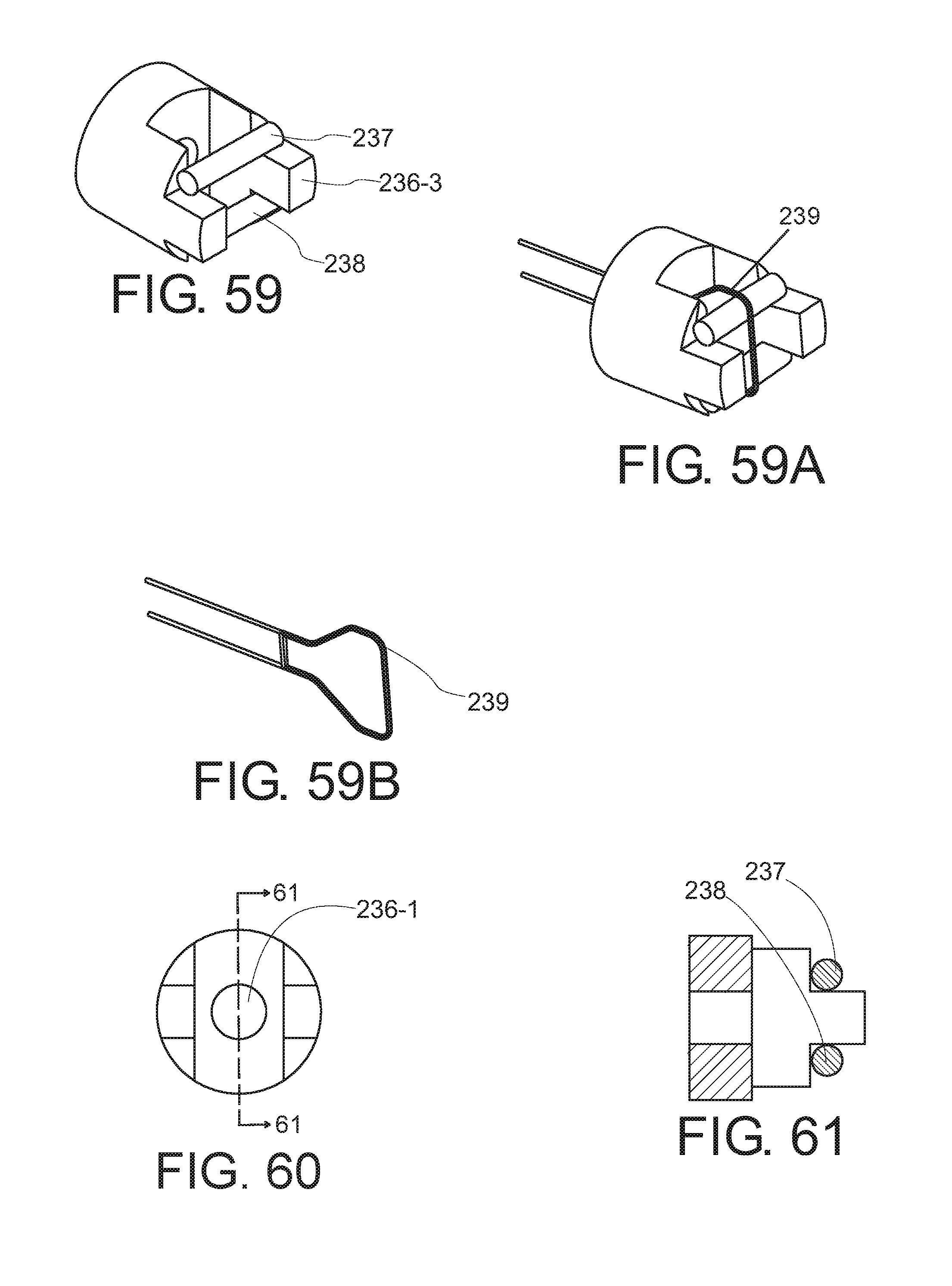
D00020

D00021

D00022

D00023

D00024

D00025

XML
uspto.report is an independent third-party trademark research tool that is not affiliated, endorsed, or sponsored by the United States Patent and Trademark Office (USPTO) or any other governmental organization. The information provided by uspto.report is based on publicly available data at the time of writing and is intended for informational purposes only.
While we strive to provide accurate and up-to-date information, we do not guarantee the accuracy, completeness, reliability, or suitability of the information displayed on this site. The use of this site is at your own risk. Any reliance you place on such information is therefore strictly at your own risk.
All official trademark data, including owner information, should be verified by visiting the official USPTO website at www.uspto.gov. This site is not intended to replace professional legal advice and should not be used as a substitute for consulting with a legal professional who is knowledgeable about trademark law.