Ear sensor
Abdul-Hafiz , et al.
U.S. patent number 10,292,657 [Application Number 15/417,640] was granted by the patent office on 2019-05-21 for ear sensor. This patent grant is currently assigned to MASIMO CORPORATION. The grantee listed for this patent is MASIMO CORPORATION. Invention is credited to Yassir Abdul-Hafiz, Ammar Al-Ali, Kevin Forrest, Eugene Mason, John Schmidt, Virginia Thanh Ta.


View All Diagrams
| United States Patent | 10,292,657 |
| Abdul-Hafiz , et al. | May 21, 2019 |
Ear sensor
Abstract
An ear sensor provides a sensor body having a base, legs extending from the base and an optical housing disposed at ends of the legs opposite the base. An optical assembly is disposed in the housing. The sensor body is flexed so as to position the housing over a concha site. The sensor body is unflexed so as to attach the housing to the concha site and position the optical assembly to illuminate the concha site. The optical assembly is configured to transmit optical radiation into concha site tissue and receive the optical radiation after attenuation by pulsatile blood flow within the tissue.
| Inventors: | Abdul-Hafiz; Yassir (Irvine, CA), Al-Ali; Ammar (San Juan Capistrano, CA), Forrest; Kevin (Rancho Santa Margarita, CA), Mason; Eugene (La Habra Heights, CA), Schmidt; John (Lake Forest, CA), Ta; Virginia Thanh (Santa Ana, CA) | ||||||||||
|---|---|---|---|---|---|---|---|---|---|---|---|
| Applicant: |
|
||||||||||
| Assignee: | MASIMO CORPORATION (Irvine,
CA) |
||||||||||
| Family ID: | 42631561 | ||||||||||
| Appl. No.: | 15/417,640 | ||||||||||
| Filed: | January 27, 2017 |
Prior Publication Data
| Document Identifier | Publication Date | |
|---|---|---|
| US 20170258403 A1 | Sep 14, 2017 | |
Related U.S. Patent Documents
| Application Number | Filing Date | Patent Number | Issue Date | ||
|---|---|---|---|---|---|
| 14218328 | Mar 18, 2014 | ||||
| 13975008 | Feb 16, 2016 | 9259185 | |||
| 12658872 | Nov 19, 2013 | 8588880 | |||
| 61152964 | Feb 16, 2009 | ||||
| Current U.S. Class: | 1/1 |
| Current CPC Class: | A61B 5/6817 (20130101); A61B 5/6867 (20130101); A61B 5/6838 (20130101); A61B 5/6815 (20130101); A61B 5/14552 (20130101); A61B 5/6816 (20130101); A61B 5/02427 (20130101); A61B 5/0261 (20130101); A61B 5/0205 (20130101) |
| Current International Class: | A61B 5/1455 (20060101); A61B 5/0205 (20060101); A61B 5/024 (20060101); A61B 5/026 (20060101); A61B 5/00 (20060101) |
References Cited [Referenced By]
U.S. Patent Documents
| 4960128 | October 1990 | Gordon et al. |
| 4964408 | October 1990 | Hink et al. |
| 5041187 | August 1991 | Hink et al. |
| 5069213 | December 1991 | Polczynski |
| 5163438 | November 1992 | Gordon et al. |
| 5319355 | June 1994 | Russek |
| 5337744 | August 1994 | Branigan |
| 5341805 | August 1994 | Stavridi et al. |
| D353195 | December 1994 | Savage et al. |
| D353196 | December 1994 | Savage et al. |
| 5377676 | January 1995 | Vari et al. |
| D359546 | June 1995 | Savage et al. |
| 5431170 | July 1995 | Mathews |
| D361840 | August 1995 | Savage et al. |
| D362063 | September 1995 | Savage et al. |
| 5452717 | September 1995 | Branigan et al. |
| D363120 | October 1995 | Savage et al. |
| 5456252 | October 1995 | Vari et al. |
| 5479934 | January 1996 | Imran |
| 5482036 | January 1996 | Diab et al. |
| 5490505 | February 1996 | Diab et al. |
| 5494043 | February 1996 | O'Sullivan et al. |
| 5533511 | July 1996 | Kaspari et al. |
| 5534851 | July 1996 | Russek |
| 5561275 | October 1996 | Savage et al. |
| 5562002 | October 1996 | Lalin |
| 5590649 | January 1997 | Caro et al. |
| 5602924 | February 1997 | Durand et al. |
| 5632272 | May 1997 | Diab et al. |
| 5638816 | June 1997 | Kiani-Azarbayjany et al. |
| 5638818 | June 1997 | Diab et al. |
| 5645440 | July 1997 | Tobler et al. |
| 5685299 | November 1997 | Diab et al. |
| D393830 | April 1998 | Tobler et al. |
| 5743262 | April 1998 | Lepper, Jr. et al. |
| 5758644 | June 1998 | Diab et al. |
| 5760910 | June 1998 | Lepper, Jr. et al. |
| 5769785 | June 1998 | Diab et al. |
| 5782757 | July 1998 | Diab et al. |
| 5785659 | July 1998 | Caro et al. |
| 5791347 | August 1998 | Flaherty et al. |
| 5810734 | September 1998 | Caro et al. |
| 5823950 | October 1998 | Diab et al. |
| 5830131 | November 1998 | Caro et al. |
| 5833618 | November 1998 | Caro et al. |
| 5860919 | January 1999 | Kiani-Azarbayjany et al. |
| 5890929 | April 1999 | Mills et al. |
| 5904654 | May 1999 | Wohltmann et al. |
| 5919134 | July 1999 | Diab |
| 5934925 | August 1999 | Tobler et al. |
| 5940182 | August 1999 | Lepper, Jr. et al. |
| 5995855 | November 1999 | Kiani et al. |
| 5997343 | December 1999 | Mills et al. |
| 6002952 | December 1999 | Diab et al. |
| 6011986 | January 2000 | Diab et al. |
| 6027452 | February 2000 | Flaherty et al. |
| 6036642 | March 2000 | Diab et al. |
| 6045509 | April 2000 | Caro et al. |
| 6067462 | May 2000 | Diab et al. |
| 6078829 | June 2000 | Uchida |
| 6080110 | June 2000 | Thorgersen |
| 6081735 | June 2000 | Diab et al. |
| 6088607 | July 2000 | Diab et al. |
| 6110522 | August 2000 | Lepper, Jr. et al. |
| 6124597 | September 2000 | Shehada |
| 6128521 | October 2000 | Marro et al. |
| 6129675 | October 2000 | Jay |
| 6144868 | November 2000 | Parker |
| 6151516 | November 2000 | Kiani-Azarbayjany et al. |
| 6152754 | November 2000 | Gerhardt et al. |
| 6157850 | December 2000 | Diab et al. |
| 6165005 | December 2000 | Mills et al. |
| 6184521 | February 2001 | Coffin, IV et al. |
| 6206830 | March 2001 | Diab et al. |
| 6229856 | May 2001 | Diab et al. |
| 6232609 | May 2001 | Snyder et al. |
| 6236872 | May 2001 | Diab et al. |
| 6241683 | June 2001 | Macklem et al. |
| 6253097 | June 2001 | Aronow et al. |
| 6256523 | July 2001 | Diab et al. |
| 6263222 | July 2001 | Diab et al. |
| 6278522 | August 2001 | Lepper, Jr. et al. |
| 6280213 | August 2001 | Tobler et al. |
| 6285896 | September 2001 | Tobler et al. |
| 6301493 | October 2001 | Marro et al. |
| 6317627 | November 2001 | Ennen et al. |
| 6321100 | November 2001 | Parker |
| 6325761 | December 2001 | Jay |
| 6334065 | December 2001 | Al-Ali et al. |
| 6343224 | January 2002 | Parker |
| 6349228 | February 2002 | Kiani et al. |
| 6360114 | March 2002 | Diab et al. |
| 6368283 | April 2002 | Xu et al. |
| 6371921 | April 2002 | Caro et al. |
| 6377829 | April 2002 | Al-Ali |
| 6388240 | May 2002 | Schulz et al. |
| 6397091 | May 2002 | Diab et al. |
| 6430437 | August 2002 | Marro |
| 6430525 | August 2002 | Weber et al. |
| 6463311 | October 2002 | Diab |
| 6470199 | October 2002 | Kopotic et al. |
| 6501975 | December 2002 | Diab et al. |
| 6505059 | January 2003 | Kollias et al. |
| 6515273 | February 2003 | Al-Ali |
| 6519487 | February 2003 | Parker |
| 6525386 | February 2003 | Mills et al. |
| 6526300 | February 2003 | Kiani et al. |
| 6541756 | April 2003 | Schulz et al. |
| 6542764 | April 2003 | Al-Ali et al. |
| 6556852 | April 2003 | Schulze et al. |
| 6580086 | June 2003 | Schulz et al. |
| 6584336 | June 2003 | Ali et al. |
| 6595316 | July 2003 | Cybulski et al. |
| 6597932 | July 2003 | Tian et al. |
| 6597933 | July 2003 | Kiani et al. |
| 6606511 | August 2003 | Ali et al. |
| 6632181 | October 2003 | Flaherty et al. |
| 6639668 | October 2003 | Trepagnier |
| 6640116 | October 2003 | Diab |
| 6643530 | November 2003 | Diab et al. |
| 6650917 | November 2003 | Diab et al. |
| 6654624 | November 2003 | Diab et al. |
| 6658276 | December 2003 | Kiani et al. |
| 6661161 | December 2003 | Lanzo et al. |
| 6671531 | December 2003 | Al-Ali et al. |
| 6678543 | January 2004 | Diab et al. |
| 6684090 | January 2004 | Ali et al. |
| 6684091 | January 2004 | Parker |
| 6697656 | February 2004 | Al-Ali |
| 6697657 | February 2004 | Shehada et al. |
| 6697658 | February 2004 | Al-Ali |
| RE38476 | March 2004 | Diab et al. |
| 6699194 | March 2004 | Diab et al. |
| 6714804 | March 2004 | Al-Ali et al. |
| RE38492 | April 2004 | Diab et al. |
| 6721582 | April 2004 | Trepagnier et al. |
| 6721585 | April 2004 | Parker |
| 6725075 | April 2004 | Al-Ali |
| 6728560 | April 2004 | Kollias et al. |
| 6735459 | May 2004 | Parker |
| 6745060 | June 2004 | Diab et al. |
| 6760607 | July 2004 | Al-Ali |
| 6770028 | August 2004 | Ali et al. |
| 6771994 | August 2004 | Kiani et al. |
| 6792300 | September 2004 | Diab et al. |
| 6813511 | November 2004 | Diab et al. |
| 6816741 | November 2004 | Diab |
| 6822564 | November 2004 | Al-Ali |
| 6826419 | November 2004 | Diab et al. |
| 6830711 | December 2004 | Mills et al. |
| 6850787 | February 2005 | Weber et al. |
| 6850788 | February 2005 | Al-Ali |
| 6852083 | February 2005 | Caro et al. |
| 6861639 | March 2005 | Al-Ali |
| 6898452 | May 2005 | Al-Ali et al. |
| 6920345 | July 2005 | Al-Ali et al. |
| 6931268 | August 2005 | Kiani-Azarbayjany et al. |
| 6934570 | August 2005 | Kiani et al. |
| 6939305 | September 2005 | Flaherty et al. |
| 6943348 | September 2005 | Coffin, IV |
| 6950687 | September 2005 | Al-Ali |
| 6961598 | November 2005 | Diab |
| 6970792 | November 2005 | Diab |
| 6979812 | December 2005 | Al-Ali |
| 6985764 | January 2006 | Mason et al. |
| 6993371 | January 2006 | Kiani et al. |
| 6996427 | February 2006 | Ali et al. |
| 6999904 | February 2006 | Weber et al. |
| 7003338 | February 2006 | Weber et al. |
| 7003339 | February 2006 | Diab et al. |
| 7015451 | March 2006 | Dalke et al. |
| 7024233 | April 2006 | Ali et al. |
| 7027849 | April 2006 | Al-Ali |
| 7030749 | April 2006 | Al-Ali |
| 7039449 | May 2006 | Al-Ali |
| 7041060 | May 2006 | Flaherty et al. |
| 7044918 | May 2006 | Diab |
| 7067893 | June 2006 | Mills et al. |
| 7096052 | August 2006 | Mason et al. |
| 7096054 | August 2006 | Abdul-Hafiz et al. |
| 7132641 | November 2006 | Schulz et al. |
| 7142901 | November 2006 | Kiani et al. |
| 7149561 | December 2006 | Diab |
| 7186966 | March 2007 | Al-Ali |
| 7190261 | March 2007 | Al-Ali |
| 7215984 | May 2007 | Diab |
| 7215986 | May 2007 | Diab |
| 7221971 | May 2007 | Diab |
| 7225006 | May 2007 | Al-Ali et al. |
| 7225007 | May 2007 | Al-Ali |
| RE39672 | June 2007 | Shehada et al. |
| 7239905 | July 2007 | Kiani-Azarbayjany et al. |
| 7245953 | July 2007 | Parker |
| 7254429 | August 2007 | Schurman et al. |
| 7254431 | August 2007 | Al-Ali |
| 7254433 | August 2007 | Diab et al. |
| 7254434 | August 2007 | Schulz et al. |
| 7272425 | September 2007 | Al-Ali |
| 7274955 | September 2007 | Kiani et al. |
| D554263 | October 2007 | Al-Ali |
| 7280858 | October 2007 | Al-Ali et al. |
| 7289835 | October 2007 | Mansfield et al. |
| 7292883 | November 2007 | De Felice et al. |
| 7295866 | November 2007 | Al-Ali |
| 7328053 | February 2008 | Diab et al. |
| 7332784 | February 2008 | Mills et al. |
| 7340287 | March 2008 | Mason et al. |
| 7341559 | March 2008 | Schulz et al. |
| 7343186 | March 2008 | Lamego et al. |
| D566282 | April 2008 | Al-Ali et al. |
| 7355512 | April 2008 | Al-Ali |
| 7356365 | April 2008 | Schurman |
| 7371981 | May 2008 | Abdul-Hafiz |
| 7373193 | May 2008 | Al-Ali et al. |
| 7373194 | May 2008 | Weber et al. |
| 7376453 | May 2008 | Diab et al. |
| 7377794 | May 2008 | Al Ali et al. |
| 7377899 | May 2008 | Weber et al. |
| 7383070 | June 2008 | Diab et al. |
| 7412272 | August 2008 | Medina |
| 7415297 | August 2008 | Al-Ali et al. |
| 7428432 | September 2008 | Ali et al. |
| 7438683 | October 2008 | Al-Ali et al. |
| 7440787 | October 2008 | Diab |
| 7454240 | November 2008 | Diab et al. |
| 7467002 | December 2008 | Weber et al. |
| 7469157 | December 2008 | Diab et al. |
| 7471969 | December 2008 | Diab et al. |
| 7471971 | December 2008 | Diab et al. |
| 7483729 | January 2009 | Al-Ali et al. |
| 7483730 | January 2009 | Diab et al. |
| 7489958 | February 2009 | Diab et al. |
| 7496391 | February 2009 | Diab et al. |
| 7496393 | February 2009 | Diab et al. |
| D587657 | March 2009 | Al-Ali et al. |
| 7499741 | March 2009 | Diab et al. |
| 7499835 | March 2009 | Weber et al. |
| 7500950 | March 2009 | Al-Ali et al. |
| 7509154 | March 2009 | Diab et al. |
| 7509494 | March 2009 | Al-Ali |
| 7510849 | March 2009 | Schurman et al. |
| 7526328 | April 2009 | Diab et al. |
| 7530942 | May 2009 | Diab |
| 7530949 | May 2009 | Al Ali et al. |
| 7530955 | May 2009 | Diab et al. |
| 7563110 | July 2009 | Al-Ali et al. |
| 7596398 | September 2009 | Al-Ali et al. |
| 7618375 | November 2009 | Flaherty |
| D606659 | December 2009 | Kiani et al. |
| 7647083 | January 2010 | Al-Ali et al. |
| D609193 | February 2010 | Al-Ali et al. |
| D614305 | April 2010 | Al-Ali et al. |
| RE41317 | May 2010 | Parker |
| 7729733 | June 2010 | Al-Ali et al. |
| 7734320 | June 2010 | Al-Ali |
| 7761127 | July 2010 | Al-Ali et al. |
| 7761128 | July 2010 | Al-Ali et al. |
| 7764982 | July 2010 | Dalke et al. |
| D621516 | August 2010 | Kiani et al. |
| 7791155 | September 2010 | Diab |
| 7801581 | September 2010 | Diab |
| 7822452 | October 2010 | Schurman et al. |
| RE41912 | November 2010 | Parker |
| 7844313 | November 2010 | Kiani et al. |
| 7844314 | November 2010 | Al-Ali |
| 7844315 | November 2010 | Al-Ali |
| 7865222 | January 2011 | Weber et al. |
| 7873497 | January 2011 | Weber et al. |
| 7880606 | February 2011 | Al-Ali |
| 7880626 | February 2011 | Al-Ali et al. |
| 7891355 | February 2011 | Al-Ali et al. |
| 7894868 | February 2011 | Al-Ali et al. |
| 7899507 | March 2011 | Al-Ali et al. |
| 7899518 | March 2011 | Trepagnier et al. |
| 7904132 | March 2011 | Weber et al. |
| 7909772 | March 2011 | Popov et al. |
| 7910875 | March 2011 | Al-Ali |
| 7919713 | April 2011 | Al-Ali et al. |
| 7937128 | May 2011 | Al-Ali |
| 7937129 | May 2011 | Mason et al. |
| 7937130 | May 2011 | Diab et al. |
| 7941199 | May 2011 | Kiani |
| 7951086 | May 2011 | Flaherty et al. |
| 7957780 | June 2011 | Lamego et al. |
| 7962188 | June 2011 | Kiani et al. |
| 7962190 | June 2011 | Diab et al. |
| 7976472 | July 2011 | Kiani |
| 7988637 | August 2011 | Diab |
| 7990382 | August 2011 | Kiani |
| 7991446 | August 2011 | Al-Ali et al. |
| 8000761 | August 2011 | Al-Ali |
| 8008088 | August 2011 | Bellott et al. |
| RE42753 | September 2011 | Kiani-Azarbayjany et al. |
| 8019400 | September 2011 | Diab et al. |
| 8028701 | October 2011 | Al-Ali et al. |
| 8029765 | October 2011 | Bellott et al. |
| 8036727 | October 2011 | Schurman et al. |
| 8036728 | October 2011 | Diab et al. |
| 8046040 | October 2011 | Ali et al. |
| 8046041 | October 2011 | Diab et al. |
| 8046042 | October 2011 | Diab et al. |
| 8048040 | November 2011 | Kiani |
| 8050728 | November 2011 | Al-Ali et al. |
| RE43169 | February 2012 | Parker |
| 8118620 | February 2012 | Al-Ali et al. |
| 8126528 | February 2012 | Diab et al. |
| 8128572 | March 2012 | Diab et al. |
| 8130105 | March 2012 | Al-Ali et al. |
| 8145287 | March 2012 | Diab et al. |
| 8150487 | April 2012 | Diab et al. |
| 8175672 | May 2012 | Parker |
| 8180420 | May 2012 | Diab et al. |
| 8182443 | May 2012 | Kiani |
| 8185180 | May 2012 | Diab et al. |
| 8190223 | May 2012 | Al-Ali et al. |
| 8190227 | May 2012 | Diab et al. |
| 8203438 | June 2012 | Kiani et al. |
| 8203704 | June 2012 | Merritt et al. |
| 8204566 | June 2012 | Schurman et al. |
| 8219172 | July 2012 | Schurman et al. |
| 8224411 | July 2012 | Al-Ali et al. |
| 8228181 | July 2012 | Al-Ali |
| 8229532 | July 2012 | Davis |
| 8229533 | July 2012 | Diab et al. |
| 8233955 | July 2012 | Al-Ali et al. |
| 8244325 | August 2012 | Al-Ali et al. |
| 8255026 | August 2012 | Al-Ali |
| 8255027 | August 2012 | Al-Ali et al. |
| 8255028 | August 2012 | Al-Ali et al. |
| 8260577 | September 2012 | Weber et al. |
| 8265723 | September 2012 | McHale et al. |
| 8274360 | September 2012 | Sampath et al. |
| 8301217 | October 2012 | Al-Ali et al. |
| 8306596 | November 2012 | Schurman et al. |
| 8310336 | November 2012 | Muhsin et al. |
| 8315683 | November 2012 | Al-Ali et al. |
| RE43860 | December 2012 | Parker |
| 8337403 | December 2012 | Al-Ali et al. |
| 8346330 | January 2013 | Lamego |
| 8353842 | January 2013 | Al-Ali et al. |
| 8355766 | January 2013 | MacNeish, III et al. |
| 8359080 | January 2013 | Diab et al. |
| 8364223 | January 2013 | Al-Ali et al. |
| 8364226 | January 2013 | Diab et al. |
| 8374665 | February 2013 | Lamego |
| 8385995 | February 2013 | Al-Ali et al. |
| 8385996 | February 2013 | Smith et al. |
| 8388353 | March 2013 | Kiani et al. |
| 8399822 | March 2013 | Al-Ali |
| 8401602 | March 2013 | Kiani |
| 8405608 | March 2013 | Al-Ali et al. |
| 8414499 | April 2013 | Al-Ali et al. |
| 8418524 | April 2013 | Al-Ali |
| 8423106 | April 2013 | Lamego et al. |
| 8428967 | April 2013 | Olsen et al. |
| 8430817 | April 2013 | Al-Ali et al. |
| 8437825 | May 2013 | Dalvi et al. |
| 8455290 | June 2013 | Siskavich |
| 8457703 | June 2013 | Al-Ali |
| 8457707 | June 2013 | Kiani |
| 8463349 | June 2013 | Diab et al. |
| 8466286 | June 2013 | Bellot et al. |
| 8471713 | June 2013 | Poeze et al. |
| 8473020 | June 2013 | Kiani et al. |
| 8483787 | July 2013 | Al-Ali et al. |
| 8489364 | July 2013 | Weber et al. |
| 8498684 | July 2013 | Weber et al. |
| 8504128 | August 2013 | Blank et al. |
| 8509867 | August 2013 | Workman et al. |
| 8515509 | August 2013 | Bruinsma et al. |
| 8523781 | September 2013 | Al-Ali |
| 8529301 | September 2013 | Al-Ali et al. |
| 8532727 | September 2013 | Ali et al. |
| 8532728 | September 2013 | Diab et al. |
| D692145 | October 2013 | Al-Ali et al. |
| 8547209 | October 2013 | Kiani et al. |
| 8548548 | October 2013 | Al-Ali |
| 8548549 | October 2013 | Schurman et al. |
| 8548550 | October 2013 | Al-Ali et al. |
| 8560032 | October 2013 | Al-Ali et al. |
| 8560034 | October 2013 | Diab et al. |
| 8570167 | October 2013 | Al-Ali |
| 8570503 | October 2013 | Vo et al. |
| 8571617 | October 2013 | Reichgott et al. |
| 8571618 | October 2013 | Lamego et al. |
| 8571619 | October 2013 | Al-Ali et al. |
| 8577431 | November 2013 | Lamego et al. |
| 8581732 | November 2013 | Al-Ali et al. |
| 8584345 | November 2013 | Al-Ali et al. |
| 8588880 | November 2013 | Abdul-Hafiz et al. |
| 8600467 | December 2013 | Al-Ali et al. |
| 8606342 | December 2013 | Diab |
| 8626255 | January 2014 | Al-Ali et al. |
| 8630691 | January 2014 | Lamego et al. |
| 8634889 | January 2014 | Al-Ali et al. |
| 8641631 | February 2014 | Sierra et al. |
| 8652060 | February 2014 | Al-Ali |
| 8663107 | March 2014 | Kiani |
| 8666468 | March 2014 | Al-Ali |
| 8667967 | March 2014 | Al-Ali et al. |
| 8670811 | March 2014 | O'Reilly |
| 8670814 | March 2014 | Diab et al. |
| 8676286 | March 2014 | Weber et al. |
| 8682407 | March 2014 | Al-Ali |
| RE44823 | April 2014 | Parker |
| RE44875 | April 2014 | Kiani et al. |
| 8690799 | April 2014 | Telfort et al. |
| 8700112 | April 2014 | Kiani |
| 8702627 | April 2014 | Telfort et al. |
| 8706179 | April 2014 | Parker |
| 8712494 | April 2014 | MacNeish, III et al. |
| 8715206 | May 2014 | Telfort et al. |
| 8718735 | May 2014 | Lamego et al. |
| 8718737 | May 2014 | Diab et al. |
| 8718738 | May 2014 | Blank et al. |
| 8720249 | May 2014 | Al-Ali |
| 8721541 | May 2014 | Al-Ali et al. |
| 8721542 | May 2014 | Al-Ali et al. |
| 8723677 | May 2014 | Kiani |
| 8740792 | June 2014 | Kiani et al. |
| 8754776 | June 2014 | Poeze et al. |
| 8755535 | June 2014 | Telfort et al. |
| 8755856 | June 2014 | Diab et al. |
| 8755872 | June 2014 | Marinow |
| 8761850 | June 2014 | Lamego |
| 8764671 | July 2014 | Kiani |
| 8768423 | July 2014 | Shakespeare et al. |
| 8771204 | July 2014 | Telfort et al. |
| 8777634 | July 2014 | Kiani et al. |
| 8781543 | July 2014 | Diab et al. |
| 8781544 | July 2014 | Al-Ali et al. |
| 8781549 | July 2014 | Al-Ali et al. |
| 8788003 | July 2014 | Schurman et al. |
| 8790268 | July 2014 | Al-Ali |
| 8801613 | August 2014 | Al-Ali et al. |
| 8821397 | September 2014 | Al-Ali et al. |
| 8821415 | September 2014 | Al-Ali et al. |
| 8830449 | September 2014 | Lamego et al. |
| 8831700 | September 2014 | Schurman et al. |
| 8840549 | September 2014 | Al-Ali et al. |
| 8847740 | September 2014 | Kiani et al. |
| 8849365 | September 2014 | Smith et al. |
| 8852094 | October 2014 | Al-Ali et al. |
| 8852994 | October 2014 | Wojtczuk et al. |
| 8868147 | October 2014 | Stippick et al. |
| 8868150 | October 2014 | Al-Ali et al. |
| 8870792 | October 2014 | Al-Ali et al. |
| 8886271 | November 2014 | Kiani et al. |
| 8888539 | November 2014 | Al-Ali et al. |
| 8888708 | November 2014 | Diab et al. |
| 8892180 | November 2014 | Weber et al. |
| 8897847 | November 2014 | Al-Ali |
| 8909310 | December 2014 | Lamego et al. |
| 8911377 | December 2014 | Al-Ali |
| 8912909 | December 2014 | Al-Ali et al. |
| 8920317 | December 2014 | Al-Ali et al. |
| 8921699 | December 2014 | Al-Ali et al. |
| 8922382 | December 2014 | Al-Ali et al. |
| 8929964 | January 2015 | Al-Ali et al. |
| 8942777 | January 2015 | Diab et al. |
| 8948834 | February 2015 | Diab et al. |
| 8948835 | February 2015 | Diab |
| 8965471 | February 2015 | Lamego |
| 8983564 | March 2015 | Al-Ali |
| 8989831 | March 2015 | Al-Ali et al. |
| 8996085 | March 2015 | Kiani et al. |
| 8998809 | April 2015 | Kiani |
| 9028429 | May 2015 | Telfort et al. |
| 9037207 | May 2015 | Al-Ali et al. |
| 9060721 | June 2015 | Reichgott et al. |
| 9066666 | June 2015 | Kiani |
| 9066680 | June 2015 | Al-Ali et al. |
| 9072474 | July 2015 | Al-Ali et al. |
| 9078560 | July 2015 | Schurman et al. |
| 9084569 | July 2015 | Weber et al. |
| 9095316 | August 2015 | Welch et al. |
| 9106038 | August 2015 | Telfort et al. |
| 9107625 | August 2015 | Telfort et al. |
| 9107626 | August 2015 | Al-Ali et al. |
| 9113831 | August 2015 | Al-Ali |
| 9113832 | August 2015 | Al-Ali |
| 9119595 | September 2015 | Lamego |
| 9131881 | September 2015 | Diab et al. |
| 9131882 | September 2015 | Al-Ali et al. |
| 9131883 | September 2015 | Al-Ali |
| 9131917 | September 2015 | Telfort et al. |
| 9138180 | September 2015 | Coverston et al. |
| 9138182 | September 2015 | Al-Ali et al. |
| 9138192 | September 2015 | Weber et al. |
| 9142117 | September 2015 | Muhsin et al. |
| 9153112 | October 2015 | Kiani et al. |
| 9153121 | October 2015 | Kiani et al. |
| 9161696 | October 2015 | Al-Ali et al. |
| 9161713 | October 2015 | Al-Ali et al. |
| 9167995 | October 2015 | Lamego et al. |
| 9176141 | November 2015 | Al-Ali et al. |
| 9186102 | November 2015 | Bruinsma et al. |
| 9192312 | November 2015 | Al-Ali |
| 9192329 | November 2015 | Al-Ali |
| 9192351 | November 2015 | Telfort et al. |
| 9195385 | November 2015 | Al-Ali et al. |
| 9211072 | December 2015 | Kiani |
| 9211095 | December 2015 | Al-Ali |
| 9218454 | December 2015 | Kiani et al. |
| 9226696 | January 2016 | Kiani |
| 9241662 | January 2016 | Al-Ali et al. |
| 9245668 | January 2016 | Vo et al. |
| 9259185 | February 2016 | Abdul-Hafiz et al. |
| 9267572 | February 2016 | Barker et al. |
| 9277880 | March 2016 | Poeze et al. |
| 9289167 | March 2016 | Diab et al. |
| 9295421 | March 2016 | Kiani et al. |
| 9307928 | April 2016 | Al-Ali et al. |
| 9323894 | April 2016 | Kiani |
| D755392 | May 2016 | Hwang et al. |
| 9326712 | May 2016 | Kiani |
| 9333316 | May 2016 | Kiani |
| 9339220 | May 2016 | Lamego et al. |
| 9341565 | May 2016 | Lamego et al. |
| 9351673 | May 2016 | Diab et al. |
| 9351675 | May 2016 | Al-Ali et al. |
| 9364181 | June 2016 | Kiani et al. |
| 9368671 | June 2016 | Wojtczuk et al. |
| 9370325 | June 2016 | Al-Ali et al. |
| 9370326 | June 2016 | McHale et al. |
| 9370335 | June 2016 | Al-ali et al. |
| 9375185 | June 2016 | Ali et al. |
| 9386953 | July 2016 | Al-Ali |
| 9386961 | July 2016 | Al-Ali et al. |
| 9392945 | July 2016 | Al-Ali et al. |
| 9397448 | July 2016 | Al-Ali et al. |
| 9408542 | August 2016 | Kinast et al. |
| 9436645 | September 2016 | Al-Ali et al. |
| 9445759 | September 2016 | Lamego et al. |
| 9466919 | October 2016 | Kiani et al. |
| 9474474 | October 2016 | Lamego et al. |
| 9480422 | November 2016 | Al-Ali |
| 9480435 | November 2016 | Olsen |
| 9492110 | November 2016 | Al-Ali et al. |
| 9510779 | December 2016 | Poeze et al. |
| 9517024 | December 2016 | Kiani et al. |
| 9532722 | January 2017 | Lamego et al. |
| 9538949 | January 2017 | Al-Ali et al. |
| 9538980 | January 2017 | Telfort et al. |
| 9549696 | January 2017 | Lamego et al. |
| 9554737 | January 2017 | Schurman et al. |
| 9560996 | February 2017 | Kiani |
| 9560998 | February 2017 | Al-Ali et al. |
| 9566019 | February 2017 | Al-Ali et al. |
| 9579039 | February 2017 | Jansen et al. |
| 9591975 | March 2017 | Dalvi et al. |
| 9622693 | April 2017 | Diab |
| 2005/0033131 | February 2005 | Chen et al. |
| 2005/0209516 | September 2005 | Fraden |
| 2007/0032715 | February 2007 | Eghbal et al. |
| 2007/0078315 | April 2007 | Kling et al. |
| 2007/0282478 | December 2007 | Al-Ali et al. |
| 2009/0010461 | January 2009 | Klinghult |
| 2009/0247984 | October 2009 | Lamego et al. |
| 2009/0275813 | November 2009 | Davis |
| 2009/0275844 | November 2009 | Al-Ali |
| 2010/0004518 | January 2010 | Vo et al. |
| 2010/0030040 | February 2010 | Poeze et al. |
| 2011/0082711 | April 2011 | Poeze et al. |
| 2011/0105854 | May 2011 | Kiani et al. |
| 2011/0125060 | May 2011 | Telfort et al. |
| 2011/0208015 | August 2011 | Welch et al. |
| 2011/0213212 | September 2011 | Al-Ali |
| 2011/0230733 | September 2011 | Al-Ali |
| 2011/0237969 | September 2011 | Eckerbom et al. |
| 2011/0288383 | November 2011 | Diab |
| 2012/0041316 | February 2012 | Al-Ali et al. |
| 2012/0046557 | February 2012 | Kiani |
| 2012/0059267 | March 2012 | Lamego et al. |
| 2012/0088984 | April 2012 | Al-Ali et al. |
| 2012/0165629 | June 2012 | Merritt et al. |
| 2012/0209082 | August 2012 | Al-Ali |
| 2012/0209084 | August 2012 | Olsen et al. |
| 2012/0283524 | November 2012 | Kiani et al. |
| 2012/0296178 | November 2012 | Lamego et al. |
| 2012/0319816 | December 2012 | Al-Ali |
| 2013/0023775 | January 2013 | Lamego et al. |
| 2013/0041591 | February 2013 | Lamego |
| 2013/0046204 | February 2013 | Lamego et al. |
| 2013/0060147 | March 2013 | Welch et al. |
| 2013/0096405 | April 2013 | Garfio |
| 2013/0096936 | April 2013 | Sampath et al. |
| 2013/0243021 | September 2013 | Siskavich |
| 2013/0253334 | September 2013 | Al-Ali et al. |
| 2013/0267804 | October 2013 | Al-Ali |
| 2013/0274572 | October 2013 | Al-Ali et al. |
| 2013/0296672 | November 2013 | O'Neil et al. |
| 2013/0296713 | November 2013 | Al-Ali et al. |
| 2013/0324808 | December 2013 | Al-Ali et al. |
| 2013/0331660 | December 2013 | Al-Ali et al. |
| 2013/0331670 | December 2013 | Kiani |
| 2014/0012100 | January 2014 | Al-Ali et al. |
| 2014/0034353 | February 2014 | Al-Ali et al. |
| 2014/0051953 | February 2014 | Lamego et al. |
| 2014/0066783 | March 2014 | Kiani et al. |
| 2014/0077956 | March 2014 | Sampath et al. |
| 2014/0081100 | March 2014 | Muhsin et al. |
| 2014/0081175 | March 2014 | Telfort |
| 2014/0100434 | April 2014 | Diab et al. |
| 2014/0114199 | April 2014 | Lamego et al. |
| 2014/0120564 | May 2014 | Workman et al. |
| 2014/0121482 | May 2014 | Merritt et al. |
| 2014/0127137 | May 2014 | Bellott et al. |
| 2014/0129702 | May 2014 | Lamego et al. |
| 2014/0135588 | May 2014 | Al-Ali et al. |
| 2014/0142401 | May 2014 | Al-Ali et al. |
| 2014/0163344 | June 2014 | Al-Ali |
| 2014/0163402 | June 2014 | Lamego et al. |
| 2014/0166076 | June 2014 | Kiani et al. |
| 2014/0171763 | June 2014 | Diab |
| 2014/0180038 | June 2014 | Kiani |
| 2014/0180154 | June 2014 | Sierra et al. |
| 2014/0180160 | June 2014 | Brown et al. |
| 2014/0187885 | July 2014 | Kreuzer |
| 2014/0187973 | July 2014 | Brown et al. |
| 2014/0213864 | July 2014 | Abdul-Hafiz et al. |
| 2014/0266790 | September 2014 | Al-Ali et al. |
| 2014/0275808 | September 2014 | Poeze et al. |
| 2014/0275835 | September 2014 | Lamego et al. |
| 2014/0275871 | September 2014 | Lamego et al. |
| 2014/0275872 | September 2014 | Merritt et al. |
| 2014/0276115 | September 2014 | Dalvi et al. |
| 2014/0288400 | September 2014 | Diab et al. |
| 2014/0316217 | October 2014 | Purdon et al. |
| 2014/0316218 | October 2014 | Purdon et al. |
| 2014/0316228 | October 2014 | Blank et al. |
| 2014/0323825 | October 2014 | Al-Ali et al. |
| 2014/0323897 | October 2014 | Brown et al. |
| 2014/0323898 | October 2014 | Purdon et al. |
| 2014/0330092 | November 2014 | Al-Ali et al. |
| 2014/0330098 | November 2014 | Merritt et al. |
| 2014/0330099 | November 2014 | Al-Ali et al. |
| 2014/0336481 | November 2014 | Shakespeare et al. |
| 2014/0357966 | December 2014 | Al-Ali et al. |
| 2015/0005600 | January 2015 | Blank et al. |
| 2015/0011907 | January 2015 | Purdon et al. |
| 2015/0012231 | January 2015 | Poeze et al. |
| 2015/0025406 | January 2015 | Al-Ali |
| 2015/0032029 | January 2015 | Al-Ali et al. |
| 2015/0038859 | February 2015 | Dalvi et al. |
| 2015/0045637 | February 2015 | Dalvi |
| 2015/0051462 | February 2015 | Olsen |
| 2015/0080754 | March 2015 | Purdon et al. |
| 2015/0087936 | March 2015 | Al-Ali et al. |
| 2015/0094546 | April 2015 | Al-Ali |
| 2015/0097701 | April 2015 | Al-Ali et al. |
| 2015/0099950 | April 2015 | Al-Ali et al. |
| 2015/0099951 | April 2015 | Al-Ali et al. |
| 2015/0099955 | April 2015 | Al-Ali et al. |
| 2015/0101844 | April 2015 | Al-Ali et al. |
| 2015/0106121 | April 2015 | Muhsin et al. |
| 2015/0112151 | April 2015 | Muhsin et al. |
| 2015/0116076 | April 2015 | Al-Ali et al. |
| 2015/0126830 | May 2015 | Schurman et al. |
| 2015/0133755 | May 2015 | Smith et al. |
| 2015/0141781 | May 2015 | Weber et al. |
| 2015/0165312 | June 2015 | Kiani |
| 2015/0196237 | July 2015 | Lamego |
| 2015/0216459 | August 2015 | Al-Ali et al. |
| 2015/0230755 | August 2015 | Al-Ali et al. |
| 2015/0238722 | August 2015 | Al-Ali |
| 2015/0245773 | September 2015 | Lamego et al. |
| 2015/0245794 | September 2015 | Al-Ali |
| 2015/0257689 | September 2015 | Al-Ali et al. |
| 2015/0272514 | October 2015 | Kiani et al. |
| 2015/0351697 | December 2015 | Weber et al. |
| 2015/0351704 | December 2015 | Kiani et al. |
| 2015/0359429 | December 2015 | Al-Ali et al. |
| 2015/0366472 | December 2015 | Kiani |
| 2015/0366507 | December 2015 | Blank |
| 2015/0374298 | December 2015 | Al-Ali et al. |
| 2015/0380875 | December 2015 | Coverston et al. |
| 2016/0000362 | January 2016 | Diab et al. |
| 2016/0007930 | January 2016 | Weber et al. |
| 2016/0029932 | February 2016 | Al-Ali |
| 2016/0045118 | February 2016 | Kiani |
| 2016/0051205 | February 2016 | Al-Ali et al. |
| 2016/0058338 | March 2016 | Schurman et al. |
| 2016/0058347 | March 2016 | Reichgott et al. |
| 2016/0066823 | March 2016 | Kind et al. |
| 2016/0066824 | March 2016 | Al-Ali et al. |
| 2016/0066879 | March 2016 | Telfort et al. |
| 2016/0072429 | March 2016 | Kiani et al. |
| 2016/0081552 | March 2016 | Wojtczuk et al. |
| 2016/0095543 | April 2016 | Telfort et al. |
| 2016/0095548 | April 2016 | Al-Ali et al. |
| 2016/0103598 | April 2016 | Al-Ali et al. |
| 2016/0113527 | April 2016 | Al-Ali et al. |
| 2016/0143548 | May 2016 | Al-Ali |
| 2016/0166182 | June 2016 | Al-Ali et al. |
| 2016/0166183 | June 2016 | Poeze et al. |
| 2016/0166188 | June 2016 | Bruinsma et al. |
| 2016/0166210 | June 2016 | Al-Ali |
| 2016/0192869 | July 2016 | Kiani et al. |
| 2016/0196388 | July 2016 | Lamego |
| 2016/0197436 | July 2016 | Barker et al. |
| 2016/0213281 | July 2016 | Eckerbom et al. |
| 2016/0228043 | August 2016 | O'Neil et al. |
| 2016/0233632 | August 2016 | Scruggs et al. |
| 2016/0234944 | August 2016 | Schmidt et al. |
| 2016/0270735 | September 2016 | Diab et al. |
| 2016/0283665 | September 2016 | Sampath et al. |
| 2016/0287090 | October 2016 | Al-Ali et al. |
| 2016/0287786 | October 2016 | Kiani |
| 2016/0296169 | October 2016 | McHale et al. |
| 2016/0310052 | October 2016 | Al-Ali et al. |
| 2016/0314260 | October 2016 | Kiani |
| 2016/0324486 | November 2016 | Al-Ali et al. |
| 2016/0324488 | November 2016 | Olsen |
| 2016/0327984 | November 2016 | Al-Ali et al. |
| 2016/0328528 | November 2016 | Al-Ali et al. |
| 2016/0331332 | November 2016 | Al-Ali |
| 2016/0367173 | December 2016 | Dalvi et al. |
| 2017/0007134 | January 2017 | Al-Ali et al. |
| 2017/0007190 | January 2017 | Al-Ali et al. |
| 2017/0007198 | January 2017 | Al-Ali et al. |
| 2017/0014084 | January 2017 | Al-Ali et al. |
| 2017/0021099 | January 2017 | Al-Ali et al. |
| 2017/0027456 | February 2017 | Kinast et al. |
| 2017/0042488 | February 2017 | Muhsin |
| 2017/0055847 | March 2017 | Kiani et al. |
| 2017/0055851 | March 2017 | Al-Ali |
| 2017/0055882 | March 2017 | Al-Ali et al. |
| 2017/0055887 | March 2017 | Al-Ali |
| 2017/0055896 | March 2017 | Al-Ali et al. |
| 2017/0079594 | March 2017 | Telfort et al. |
| 2017/0086723 | March 2017 | Al-Ali et al. |
| 191409166 | Jul 1914 | GB | |||
| WO 2007/100959 | Sep 2007 | WO | |||
| WO 2011/102846 | Aug 2011 | WO | |||
Other References
|
US 9,579,050 B2, 02/2017, Al-Ali (withdrawn) cited by applicant . U.S. Appl. No. 14/218,328, Ear Sensor, filed Mar. 18, 2014. cited by applicant . PCT International Search Report; PCT/US2010/033796; dated Oct. 17, 2011; pp. 1-4. cited by applicant. |
Primary Examiner: Winakur; Eric F
Assistant Examiner: Fardanesh; Marjan
Attorney, Agent or Firm: Knobbe Martens Olson & Bear LLP
Parent Case Text
CROSS-REFERENCE TO RELATED APPLICATIONS
The present application is a continuation of U.S. patent application Ser. No. 14/218,328, filed Mar. 18, 2014, titled "Ear Sensor," which is a continuation of U.S. patent application Ser. No. 13/975,008, filed Aug. 23, 2013, titled "Ear Sensor," which is a continuation of U.S. patent application Ser. No. 12/658,872, filed Feb. 16, 2010, titled "Ear Sensor," which claims priority benefit under 35 U.S.C. .sctn. 119(e) to U.S. Provisional Patent Application No. 61/152,964, filed Feb. 16, 2009, titled "Ear Sensor," each of which is hereby incorporated by reference herein in its entirety.
Claims
What is claimed is:
1. An in-ear physiological measurement device comprising: a base portion; an extension portion configured to extend at least partially into an ear of a user, the extension portion including: an outer surface that extends substantially cylindrically around an axis of the extension portion and is configured to be positioned at least partially in the ear of the user, wherein the axis extends from the base portion to an end of the extension portion configured to be positioned in the ear of the user; and an end surface that joins the outer surface at the end of the extension portion; at least one light emitter configured to emit light into an ear tissue site of the user; and at least one light detector configured to output a signal responsive to at least a portion of the emitted light after attenuation by ear tissue of the ear tissue site, the signal indicative of at least one physiological parameter of the user, wherein the at least one light emitter and at least one light detector are positioned on the outer surface of the substantially cylindrical extension portion and not on the end surface of the extension portion, and wherein the at least one light emitter and the at least one light detector are positioned spaced apart relative to each other along an axis parallel to the axis of the extension portion.
2. The in-ear physiological measurement device of claim 1, wherein the at least one of the base portion or the extension portion is configured to conform to a portion of the ear of the user including at least one of a portion of a concha or a portion of an ear canal of the ear of the user.
3. The in-ear physiological measurement device of claim 2, wherein the extension portion narrows toward the end of the extension portion.
4. The in-ear physiological measurement device of claim 3, wherein the base portion is wider than the extension portion so as to be configured to stay outside the ear of the user.
5. The in-ear physiological measurement device of claim 2 further comprising: an expanding material portion, wherein the in-ear physiological measurement device is configured to be mounted in the ear of the user by first squeezing and then releasing the expanding material portion after placement of the in-ear physiological measurement device in the ear.
6. The in-ear physiological measurement device of claim 5, wherein the expanding material portion is configured to mount the in-ear physiological measurement device in the concha and/or ear canal of the ear of the user.
7. The in-ear physiological measurement device of claim 6, wherein the expanding material portion comprises a foam material.
8. The in-ear physiological measurement device of claim 7 further comprising: a cable portion extending from the base portion and configured to communicate the signal to a receiver, the signal useable by the receiver to determine the at least one physiological parameter of the user.
9. The in-ear physiological measurement device of claim 8, wherein at least one of: the base portion, the extension portion, or a combination of the base portion and the extension portion comprises an ear bud.
10. The in-ear physiological measurement device of claim 7, wherein the ear tissue of the ear tissue site includes at least one of ear canal ear tissue or concha ear tissue.
11. The in-ear physiological measurement device of claim 10, wherein the portion of the emitted light is reflected by the ear tissue to the at least one light detector.
12. The in-ear physiological measurement device of claim 11, wherein the at least one physiological parameter comprises at least one of an oxygen saturation or a pulse rate of the user.
13. The in-ear physiological measurement device of claim 12, wherein the base portion is configured to conform to a concha of the ear of the user.
14. The in-ear physiological measurement device of claim 13 further comprising: at least one additional light emitter and at least one additional light detector positioned on the base portion.
15. A multi-site in-ear physiological measurement system comprising: two in-ear physiological measurement devices according to claim 1, each in-ear physiological measurement device configured to be simultaneously placed in either a right or left ear of the user; and a monitoring device configured to receive the signal from each of the two in-ear physiological measurement devices, the signals useable by the monitoring device to determine the at least one physiological parameter of the user.
16. The multi-site in-ear physiological measurement system of claim 15, wherein both of the two in-ear physiological measurement devices are coupled to a single flexible frame.
17. An in-ear physiological measurement system comprising: an in-ear physiological measurement device according to claim 1, the in-ear physiological measurement device configured to be placed in at least one of a right or left ear of the user; and a monitoring device configured to receive the signal from the in-ear physiological measurement device, the signal useable by the monitoring device to determine the at least one physiological parameter of the user.
Description
BACKGROUND OF THE INVENTION
Pulse oximetry systems for measuring constituents of circulating blood have gained rapid acceptance in a wide variety of medical applications, including surgical wards, intensive care and neonatal units, general wards, home care, physical training, and virtually all types of monitoring scenarios. A pulse oximetry system generally includes an optical sensor applied to a patient, a monitor for processing sensor signals and displaying results and a patient cable electrically interconnecting the sensor and the monitor. A pulse oximetry sensor has light emitting diodes (LEDs), typically one emitting a red wavelength and one emitting an infrared (IR) wavelength, and a photodiode detector. The emitters and detector are typically attached to a finger, and the patient cable transmits drive signals to these emitters from the monitor. The emitters respond to the drive signals to transmit light into the fleshy fingertip tissue. The detector generates a signal responsive to the emitted light after attenuation by pulsatile blood flow within the fingertip. The patient cable transmits the detector signal to the monitor, which processes the signal to provide a numerical readout of physiological parameters such as oxygen saturation (SpO.sub.2) and pulse rate.
Pulse oximeters capable of reading through motion induced noise are disclosed in at least U.S. Pat. Nos. 6,770,028, 6,658,276, 6,650,917, 6,157,850, 6,002,952, 5,769,785, and 5,758,644; low noise pulse oximetry sensors are disclosed in at least U.S. Pat. Nos. 6,088,607 and 5,782,757; all of which are assigned to Masimo Corporation, Irvine, Calif. ("Masimo") and are incorporated by reference herein. An ear sensor is disclosed in U.S. Pat. No. 7,341,559 titled Pulse Oximetry Ear Sensor, also assigned to Masimo and also incorporated by reference herein.
Advanced physiological monitoring systems may incorporate pulse oximetry in addition to advanced features for the calculation and display of other blood parameters, such as carboxyhemoglobin (HbCO), methemoglobin (HbMet) and total hemoglobin (Hbt), as a few examples. Advanced physiological monitors and corresponding multiple wavelength optical sensors capable of measuring parameters in addition to SpO.sub.2, such as HbCO, HbMet and Hbt are described in at least U.S. patent application Ser. No. 12/056,179, filed Mar. 26, 2008, titled Multiple Wavelength Optical Sensor and U.S. patent application Ser. No. 11/366,208, filed Mar. 1, 2006, titled Noninvasive Multi-Parameter Patient Monitor, both incorporated by reference herein. Further, noninvasive blood parameter monitors and corresponding multiple wavelength optical sensors, such as Rainbow.TM. adhesive and reusable sensors and RAD-57.TM. and Radical-7.TM. monitors for measuring SpO.sub.2, pulse rate, perfusion index (PI), signal quality (SiQ), pulse variability index (PVI), HbCO and HbMet among other parameters are also available from Masimo.
SUMMARY OF THE INVENTION
FIG. 1 illustrates various areas of the ear 100 that are amenable to blood parameter measurements, such as oxygen saturation (SpO.sub.2). An ear site has the advantage of more quickly and more accurately reflecting oxygenation changes in the body's core as compared to peripheral site measurements, such as a fingertip. Conventional ear sensors utilize a sensor clip on the ear lobe 110. However, significant variations in lobe size, shape and thickness and the general floppiness of the ear lobe render this site less suitable for central oxygen saturation measurements than the concha 120 and the ear canal 130. Disclosed herein are various embodiments for obtaining noninvasive blood parameter measurements from concha 120 and ear canal 130 tissue sites.
One aspect of an ear sensor optically measures physiological parameters related to blood constituents by transmitting multiple wavelengths of light into a concha site and receiving the light after attenuation by pulsatile blood flow within the concha site. The ear sensor comprises a sensor body, a sensor connector and a sensor cable interconnecting the sensor body and the sensor connector. The sensor body comprises a base, legs and an optical assembly. The legs extend from the base to detector and emitter housings. An optical assembly has an emitter and a detector. The emitter is disposed in the emitter housing and the detector is disposed in the detector housing. The legs have an unflexed position with the emitter housing proximate the detector housing and a flexed position with the emitter housing distal the detector housing. The legs are moved to the flexed position so as to position the detector housing and emitter housing over opposite sides of a concha site. The legs are released to the unflexed position so that the concha site is grasped between the detector housing and emitter housing.
In various embodiments, the ear sensor has a resilient frame and a one piece molded skin disposed over the resilient frame. A cup is disposed proximate the detector housing and has a surface that generally conforms to the curvature of the concha site so as to couple the detector to the concha site and so as to block ambient light. A sensor cable has wires extending from one end of the sensor cable and disposed within channels defined by the resilient frame. The wires electrically and mechanically attach to the optical assembly. A connector is attached to the other end of the sensor cable, and the cable wires electrically and mechanically attach to the connector so as to provide communications between the connector and the optical assembly.
In other embodiments, a stabilizer maintains the position of the detector housing and the emitter housing on the concha site. The stabilizer may have a ring that encircles the legs. The ring has a hold position disposed against the legs and a release position spaced from the legs. A release, when pressed, moves the ring from the hold position to the release position, allowing the ring to slidably move along the legs in a direction away from the base so as to increase the force of the emitter housing and detector housing on the concha site in the hold position and in a direction toward the base so as to decrease the force of the emitter housing and the detector housing on the concha site in the hold position. The stabilizer may have an ear hanger that rests along the back of the ear and couples to at least one of the legs and the sensor cable.
Another aspect of an ear sensor comprises providing a sensor body having a base, legs extending from the base and an optical housing disposed at ends of the legs distal the base. An optical assembly is disposed in the housing. The sensor body is flexed so as to position the housing over a concha site. The sensor body is unflexed so as to attach the housing to the concha site and position the optical assembly to illuminate the concha site.
In various embodiments, an ear surface conforming member is molded to at least a portion of the housing so as to physically couple the housing to the concha site and block ambient light from the optical assembly accordingly. The force of the housing against the concha site is adjusted. The adjusting comprises positioning a force adjustment ring on the sensor body so as to encircle the legs. The positioning comprises squeezing a ring release so as to move ring grips away from the legs, moving the force adjustment ring along the legs and toward the housing so as to increase the force of the housing on the concha site, and moving the force adjustment ring along the legs and away from the housing so as to decrease the force of the housing on the concha site.
In other embodiments, an aspect of the ear sensor comprises supporting at least a portion of the weight of the sensor body and corresponding sensor cable so as to reduce the force needed to attach the housing to the concha site. The supporting comprises attaching at least one of the sensor body and sensor cable to an ear hook placed over the ear.
A further aspect of an ear sensor comprising a clip means having a flexed position and an unflexed position. An optical means transmits multiple wavelength light into a tissue site when activated and receives the light after attenuation by pulsatile blood flow within the tissue site. The optical means is disposed on the clip means so that the optical means can be positioned on a concha site in the flexed position and pinched against the concha site in the unflexed position. A connector means mechanically attaches to and electrically communicates with a monitor. A cable means interconnects the connector means with the optical means. In various embodiments, the clip means comprises a resilient frame means for securing the optical means in a fixed position relative to the tissue site. A housing means encloses the resilient frame means and the optical means. A cup means physically couples at least a portion of the optical means to the concha site and blocks ambient light from the optical means. An adjustable force means holds the clip means to the concha site. Alternatively, or in addition to, a support means holds the clip means to the concha site.
BRIEF DESCRIPTION OF THE DRAWINGS
FIG. 1 is an illustration of the pinna or external ear structure, including the concha;
FIGS. 2A-B and 3A-B illustrate various ear sensor embodiments;
FIGS. 2A-B are a side view and a perspective view of an ear bud embodiment of an ear sensor;
FIGS. 3A-B are perspective views of a flexible ear pad embodiment of an ear sensor;
FIGS. 4A-D, 5A-B, 6A-B, and 7A-C illustrate various ear bud/pad attachment embodiments for a concha site;
FIGS. 4A-D are side views of "C"-clip embodiments for attaching an ear sensor to a concha site;
FIGS. 5A-B are perspective views of alligator clip embodiments for attaching an ear sensor to a concha site;
FIGS. 6A-B are perspective views of a clear adhesive disk embodiment for attaching an ear sensor to a concha site;
FIGS. 7A-C are perspective views of a flexible magnet disk embodiment for attaching an ear sensor to a concha site;
FIGS. 8A-B, 9A-B, and 10A-B illustrate various "hearing aid" style ear sensor embodiments that integrate the ear sensor with an attachment mechanism;
FIGS. 8A-B illustrate a concha-placed reflective sensor embodiment;
FIGS. 9A-B illustrate an "in-the-canal" reflective sensor embodiment;
FIGS. 10A-B illustrate "behind-the-ear" transmissive and/or reflective sensor embodiments;
FIGS. 11A-B and 12A-F illustrate additional integrated ear sensor and attachment embodiments;
FIGS. 11A-B illustrate an integrated ear lobe attachment and concha-placed sensor embodiment;
FIGS. 12A-F illustrate a "Y"-clip sensor embodiment for concha-placement;
FIGS. 13A-F, 14A-B, 15A-B, and 16 illustrate various ear sensor attachment support embodiments;
FIGS. 13A-F are side views of ear-hook support embodiments;
FIGS. 14A-B are perspective views of headband support embodiments;
FIGS. 15A-B are front and perspective views of a "stethoscope" support embodiment;
FIG. 16 is a perspective view of a "headphone" support embodiment;
FIGS. 17A-B, 18A-E, 19, 20A-B, 21A-B, 22A-B, 23A-B, 24A-C, 25A-E, 26A-F, and 27A-F illustrate a concha-clip sensor embodiment having an orthogonally-routed sensor cable;
FIGS. 17A-B are perspective views of a concha-clip sensor;
FIGS. 18A-E are top, perspective, front, detector-side and emitter-side views, respectively, of a concha-clip sensor body;
FIG. 19 is an exploded view of an concha-clip sensor;
FIGS. 20A-B are assembly and detailed assembly views of a concha-clip sensor;
FIG. 21A-B are a mechanical representation and a corresponding electrical (schematic) representation of a concha-clip sensor having a DB9 connector;
FIG. 22A-B are a mechanical representation and a corresponding electrical (schematic) representation of a concha-clip sensor having a MC8 connector;
FIG. 23A-B are a mechanical representation and a corresponding electrical (schematic) representation of a concha-clip sensor having a M15 connector;
FIGS. 24A-C are assembly step representations for installing an optical assembly into a resilient frame and installing the resilient frame into a sensor housing;
FIGS. 25A-E are top, perspective, front, side cross-section; and side views, respectively, of a force adjustment ring;
FIGS. 26A-F are top, disassembled perspective, assembled perspective, front, detector-side and emitter-side views of a concha-clip sensor body and corresponding force adjustment ring; and
FIGS. 27A-F are top, bottom, perspective, detector-side, front, emitter side and perspective views, respectively of an concha-clip sensor body having a parallel-routed sensor cable.
DETAILED DESCRIPTION OF THE PREFERRED EMBODIMENTS
FIGS. 2A-B illustrate an ear bud embodiment of an ear sensor 200 having an emitter ear bud 210, a detector ear bud 220 and connecting cables 230. The emitter ear bud 210 has a generally concave surface for attachment to the back of an ear. The detector ear bud 220 has a generally convex surface 222 for attachment inside the ear at a concha site opposite the emitter ear bud 210. Sensor cables 230 are attached at the back of each ear bud having wires for electrical communications with a physiological monitor, such as a pulse oximeter. In particular, the emitter ear bud 210 includes wires for receiving emitter drive current from a monitor and the detector ear bud 220 includes wires for transmitting photodiode current to the monitor.
FIGS. 3A-B illustrate a flexible ear pad embodiment of an ear sensor 300 having an emitter pad 310, a detector pad 320 and corresponding cables 330. The sensor pads 310, 320 advantageously include a housing for each of the emitter pad 310 and the detector pad 320, minimizing the number of unique parts for the ear sensor. The detector pad 320 houses a shielded detector assembly (not shown). The emitter pad houses 310 an emitter (not shown). Both the detector pad 320 and the emitter pad 310 are connected to a sensor cable 330. The pads 310, 320 have an integrated bend relief 304 providing a finger grip. The pad face 306 provides a generally planar, pliant contact surface that can adapt to the curved front and back surfaces of a concha site. The pad face 306 has a relatively large area to minimize contact force. The housing 302 is injection molded of a pliant material. In one embodiment, the material is a medical grade thermoplastic elastomer.
FIGS. 2A-B and 3A-B, above, illustrate various ear sensor embodiments. Although described with respect to ear bud and flexible ear pad enclosures, the sensor emitter and detector may be enclosed in any number of housings having various sizes and shapes of ear tissue contact surfaces, may use various types of electrical interconnnect and use various materials so as to noninvasively measure blood parameters from the concha area of the ear. As an example, the detector and emitter may both be mounted at one end of a "Y"-shaped flex circuit that has a connector at the opposite end. Although described above with respect to a detector placed inside the ear and an emitter placed outside the ear, a suitable alternative is the emitter inside and the detector outside the ear. Detector and emitter assemblies are described with respect to FIGS. 19-20, below.
FIGS. 4A-D illustrate "C"-clip embodiments 400 for attaching an ear sensor 410 to a concha site. The clip 400 is adapted for use with either the ear bud or the ear pad embodiments described above. The clip 400 has sensor mounts 420 fixedly attached to each end of a flexible "C"-shaped body 422. The body 422 is made of a suitable material having an appropriate stiffness so as to provide a comfortable yet secure attachment to ear tissue. The sensor mounts 420 have mounting apertures sized for the ear buds or ear pads described above. The ear buds or pads are secured within the apertures with a friction fit or adhesive. In an alternative embodiment, the sensor housings are molded or otherwise integrated with the sensor mounts.
As shown in FIGS. 4A-B, in one embodiment 401 the unflexed clip 400 (FIG. 4A) is compressed between fingertips so that the clip ends 424 are crossed (FIG. 4B) and the contact surfaces of the ear sensor 412 are facing each other. The clip 400 is placed over the ear so that the detector and emitter ear buds are on opposite sides of the ear. Finger pressure on the clip 400 is then released so that the clip tension holds the sensor contact surfaces 412 against the concha tissue. As shown in FIGS. 4C-D, in another embodiment 403 the clip ends 424 are crossed in both the flexed position (FIG. 4C) and the unflexed position (FIG. 4D). Otherwise, sensor attachment is as described above. Although described above as a "C"-shape, the clip body can be constructed of any of various springy, pre-formed materials having a variety of shapes and sizes so as to attach to ear tissue via compression and release between finger and thumb.
FIGS. 5A-B illustrate an alligator clip embodiment for attaching an ear sensor to a concha site. The alligator clip 500 has opposing heads 510, each with a thru-hole 512 sized to accommodate either an ear pad sensor 300 (FIG. 5A) or an ear bud sensor 200 (FIG. 5B). The alligator clip 500 also has finger grips 520 each with a channel 530 for routing the sensor cabling 540. The alligator clip is compressed and released to position and then attach the corresponding ear sensor to a concha site.
FIGS. 6A-B illustrate an adhesive disk embodiment for attaching an ear sensor to a concha site. Clear disks 600 have an adhesive on both surfaces. The adhesive is bio-compatible on at least the tissue-facing surface. The disks 600 are first attached to the sensor 200 or to a concha site 10. Then the ear sensor 200 is attached on opposite sides of the concha tissue 10. The disks 600 are sized to accommodate either an ear bud sensor 200, as shown, or an ear pad sensor 300 (FIGS. 3A-B).
FIGS. 7A-C illustrate a flexible magnet disk embodiment for attaching an ear sensor to a concha site. Flexible magnetic disks 700, such as made from a mixture of a ferrite powder and a rubber polymer resin, are permanently or temporarily attached to an ear sensor 200. The attachment may be by friction fit or a removable or permanent adhesive. The ear sensor 200 is then placed on opposite sides of the concha site 10 and held in place by the magnetic force of the disks. One or both disks may be permanently magnetized during manufacture. The disks 700 are sized to accommodate either the ear bud sensor 200, as shown, or the ear pad sensor 300 (FIGS. 3A-B). In an alternative embodiment, each of the ear sensor housings is at least partially composed of a high magnetic permeable material. One or both of the housings are magnetized. In another embodiment, one or more rare earth magnets are embedded in one or both housings.
FIGS. 4A-D, 5A-B, 6A-B, and 7A-C, described above, illustrate various ear sensor attachment embodiments. Although described with respect to clips and adhesive or magnetic disks, the sensor emitter and detector may be attached to an ear tissue site using various other materials and mechanisms. For example, ear buds or pads may attach via suction cups or disks. Also, an emitter and detector may be integrated with disposable adhesive pads configured with snaps or other mechanical connectors for attaching and removing sensor leads from the disposable pads. In another embodiment, a sensor may be mounted in the concha or the ear canal using an expanding foam material that is first squeezed and then released after sensor placement within the ear.
FIGS. 8A-B illustrate a concha-placed reflective sensor embodiment. In one embodiment the sensor 800 has an ear canal extension 810 (FIG. 8B). In an embodiment, the ear canal extension has at least one emitter and at least one detector disposed proximate the extension surface so as to transmit light into ear canal tissue and to detect the transmitted light after attenuation by pulsatile blood flow within the ear canal tissue. In an embodiment, the emitter and detector are axially spaced on the extension. In an embodiment, the emitter and detector are radially spaced on the extension at a fixed angle, which may be, as examples, 30, 45, 90, 120, 135, 160 or 180 degrees.
In an embodiment, the concha-placed sensor body 820 has at least one emitter and at least one detector in lieu of an ear canal extension emitter and detector. The sensor body emitter and detector are disposed proximate the concha surface so as to transmit light into concha tissue and to detect the transmitted light after attenuation by pulsatile blood flow within the concha tissue. In an embodiment, the concha-placed sensor body 820 and the ear canal extension 810 both have at least one emitter and at least one detector, creating a multi-site (concha and ear canal) reflective sensor. Connected with the sensor body 820 is a sensor cable 830 providing electrical communications between sensor body/ear canal emitter(s) and detector(s) and a monitor. Detector and emitter assemblies are described with respect to FIGS. 19-20, below.
FIGS. 9A-B illustrate an "in-the-canal" ear sensor embodiment. The ear canal sensor 900 has a base 910, an ear canal extension 920 and a sensor cable 930. Similar to the embodiment described above, the ear canal extension 920 has at least one emitter 922 and at least one detector 924 disposed proximate the extension surface so as to transmit light into ear canal tissue and to detect the transmitted light after attenuation by pulsatile blood flow within the ear canal tissue. The emitter 922 and detector 924 may be axially-spaced on the ear canal extension a fixed distance. Alternatively, the emitter and detector may be radially-spaced on the ear canal extension at any of various angles, such as 30, 45, 90, 120, 135, 160 or 180 degrees, to name a few. A sensor cable 930 is attached to the sensor so as to extend from the ear canal to a corresponding monitor.
FIGS. 10A-B illustrate "behind-the-ear" transmissive and/or reflective sensor embodiments. The ear sensor 1000 has a concha-placed body 1010, an ear piece 1020, a connecting piece 1030 attaching the concha body 1010 and the ear piece 1020 and a sensor cable 1040. In one embodiment, a concha-placed body 1010 houses a detector and the ear piece 1020 houses an emitter opposite the detector so as to configure a transmissive concha sensor. In an embodiment, the concha-placed body 1010 or the ear piece 1020 has both an emitter and a detector so as to configure a reflective concha sensor. In an embodiment, the concha body 1010 and the ear piece 1020 are configured for multi-site transmissive and/or reflective concha tissue measurements. In an embodiment, the concha body 1010 also has an ear canal extension (see, e.g. 810 FIG. 8B), which may also have an emitter and detector for multi-site concha and ear canal measurements. A sensor cable 1040 extends from the ear piece 1020 as shown. Alternatively, a sensor cable extends from the concha body, such as shown in FIG. 8B, above.
FIGS. 11A-B illustrate a concha sensor 1100 having an alligator clip 1110, a concha piece 1120, a ear back piece 1130, a lobe attachment 1140 and a sensor cable 1150. In an embodiment, the alligator clip 1110 attaches to the ear lobe 20 so as to provide the physical support for a concha sensor 1100. A convex body 1122 extends from the concha piece 1120. A detector disposed at the convex body 1122 surface is disposed against the concha tissue 10. A concave surface 1132 is defined on the back piece 1130 and positioned behind the ear. An emitter disposed at the concave surface 1132 is disposed against the ear wall opposite the concha detector. The concha piece 1120 and ear back piece 1130 are "springy" so as to securely contact the concha tissue 10 under the force of the alligator clip 1110, but without undue discomfort. In an embodiment, the lobe attachment 1140 also has an emitter and detector so as to provide multi-site ear tissue measurements at the ear lobe 20 and the concha 10.
FIGS. 12A-F illustrate a "Y"-clip ear sensor 1200 having a base 1210, a pair of curved clips 1220 extending from the base, an emitter assembly 1230 extending from one clip end and a detector assembly 1240 extending from another clip end. The clips 1220 are tubular so as to accommodate wires from the emitter/detector assemblies, which extend from apertures 1212 in the base. Each assembly has a pad 1232, a molded lens 1234 and a lid 1236, which accommodate either an emitter subassembly or a detector subassembly. The Y-"clips" flex so as to slide over the ear periphery and onto either side of the concha. The integrated emitter and detector, so placed, can then transmit multiple wavelength light into the concha tissue and detect that light after attenuation by pulsatile blood flow within the concha tissue.
FIGS. 13A-F illustrate ear hook sensor support embodiments having an ear hook 1300 with cable 1310, fixed 1320 or sliding 1330 support for either an alligator clip or a "Y"-clip sensor. These embodiments are also applicable to "C"-clip sensors and alligator clip sensors, among others.
FIGS. 14A-B illustrate headband sensor support embodiments. In one embodiment, the headband 1400 secures a concha body (FIGS. 8A-B) or an ear canal sensor (FIGS. 9A-B) by placement over the ear. In another embodiment, the headband 1400 provides a cable support for an ear clip sensor.
FIGS. 15A-B illustrate a "stethoscope" 1500 sensor support embodiment. In this embodiment, one ear piece 1510 is integrated with an ear canal sensor 1520, such as described above with respect to FIGS. 9A-B. In another embodiment, both stethoscope ear pieces 1510 are integrated with ear canal sensors for multi-site (both ears) blood parameter measurements.
FIG. 16 illustrates a "headphone" 1600 support embodiment. In one embodiment (not shown), a headphone ear piece secures a concha body (FIGS. 8A-B) or an ear canal sensor (FIGS. 9A-B) by placement over the ear, in a similar manner as described with respect to FIGS. 14A-B. In another embodiment, the headphone 1600 provides a "ring-shaped" earpiece 1610 that provides a cable support 1612 for an ear clip sensor 1200, as shown.
FIGS. 17A-B illustrate a concha-clip ear sensor 1700 embodiment having a sensor body 1800, a connector 1710 and a sensor cable 1720 providing communications between the sensor body 1800 and the connector 1710. As described in further detail with respect to FIGS. 18A-E, the sensor body 1800 has resilient legs that are manually flexed so as to slide over an ear periphery and onto either side of a concha site. As described in further detail with respect to FIG. 19, the sensor body 1800 incorporates an optical assembly 1910 (FIG. 19) configured to transmit multiple wavelength light into the concha tissue and detect that light after attenuation by pulsatile blood flow within the concha tissue. In a particular embodiment, the sensor body 1800 has an emitter housing 1840 (FIGS. 18A-E) configured to fit inside the ear and a detector housing 1850 (FIGS. 18A-E) configured to fit outside the ear. In other embodiments, the sensor body is configured so as to place an emitter outside the ear and a detector inside the ear. In an embodiment, the sensor body 1800 is configured so that the sensor cable 1720 extends generally perpendicular to the sensor body 1800, as shown and described with respect to FIGS. 17-26. In another sensor body embodiment 2700 (FIGS. 27A-F) the sensor cable 1720 extends generally parallel to the sensor body, as described in further detail with respect to FIGS. 27A-E, below. Although the sensor body 1800, 2700 as described below has legs 1830 extending from a base 1810 so as to generally form a "U"-shape, the sensor body 1800, 2700 can be constructed of any of various resilient, pre-formed materials having a variety of shapes and sizes so as to attach to ear tissue, such as a concha site or ear lobe site.
FIGS. 18A-E further illustrate a sensor body 1800 having a base 1810, a strain relief 1820 formed at a side of the base 1810 and a pair of resilient legs 1830 extending from the base 1810. The strain relief 1820 has a cable aperture 1822 that accommodates the sensor cable 1720 (FIGS. 17A-B). An emitter housing 1840 extends from one leg 1830 and a detector housing 1850 extends from the other leg 1830. The legs 1830 accommodate cable conductors extending between the connector 1710 (FIGS. 17A-B) and an optical assembly 1910 (FIG. 19) located in the housings 1840, 1850. Each housing 1840, 1850 has an optical end 1842, 1852 (FIG. 20B) having an aperture 1844, 1854 (FIG. 20B) that passes light from the emitter housing 1840 to the detector housing 1850. In an embodiment, the housings 1840, 1850 fit on either side of a concha tissue site so that light is transmitted from an emitter 1916 (FIG. 19), through the concha tissue and received by a detector 1912 (FIG. 19), as described in detail below. In an embodiment, the emitter housing 1840 fits within the ear and the detector housing 1850 outside the ear. In an embodiment, a cup 1860 extends from the detector housing 1850. The cup 1860 has a generally circular edge and a curvature that accommodates the surface behind the ear. Accordingly, the cup 1860 advantageously provides a more comfortable and secure fit of the detector housing 1850 to the ear and further functions as a light shield, blocking external light sources from the detector 1912. The resilent legs 1830 are manually flexed so that the emitter housing 1840 is moved away from the detector housing 1850 so as to position the detector housing 1850 and emitter housing 1840 over opposite sides of a concha site. The legs are then released to an unflexed position so that the concha site is grasped between the detector housing 1850 and emitter housing 1840.
FIGS. 19, 20A-B further illustrates a concha-clip ear sensor 1700 having a connector 1710 in communications with a sensor body 1800 via a sensor cable 1720. The sensor body 1800 has an optical assembly 1910, a resilient frame 1920, a sensor housing 1930 and lenses 1940. As shown in FIGS. 19-20, the optical assembly 1910 has a detector 1912, a detector shield 1914, a light barrier 1915, an emitter 1916 and white electrical tape 1918. The cable 1720 has emitter wires 1722 and detector wires 1724 that are soldered to the emitter 1916 and detector 1912, respectively, and communicate emitter drive signals and detector response signals to/from the connector 1710.
Also shown in FIGS. 19, 20A-B, the resilient frame 1920 has an emitter channel 1926 terminating at an emitter holder 1924, a detector channel 1927 terminating at a detector holder 1925, a strain relief 1928 and a frame hole 1929. The optical assembly 1910 fits within the resilient frame 1920. In particular, the emitter wires 1722 are disposed within the emitter channel 1926, the detector wires 1724 are disposed in the detector channel 1927, the emitter is disposed in the emitter holder 1924 and the detector 1912 and corresponding shield 1914 and light barrier 1915 are disposed in the detector holder 1925. In an embodiment, the sensor housing 1930 is a one piece silicon skin disposed over the resilient frame 1920 and the optical assembly 1910, as described with respect to FIGS. 24A-C, below. In an embodiment, the resilient frame 1920 is a polypropylene/santoprene blend. The lenses 1940 are disposed within housing apertures 1844, 1854. In an embodiment, the lenses 1940 are formed from a translucent silicone adhesive. In an alternative embodiment, the lenses 1940 are separately formed from clear silicone and glued into place with a translucent silicone adhesive.
FIGS. 21A-B, 22A-B, 23A-B further illustrate concha-clip sensor embodiments 2100, 2200, 2300 having a DB9 connector 2130 (FIGS. 21A-B), a MC8 connector 2230 (FIGS. 22A-B) or a M15 connector 2330 (FIGS. 23A-B). The sensor bodies 2110, 2220, 2330 have red and IR emitters 2112, 2212, 2312 and detectors 2114, 2214, 2314 in communication with connectors 2130, 2230, 2330 via emitter wires 2152, 2252, 2352 and detector wires 2154, 2254, 2354. Sensor ID resistors 2132, 2232, 2332 are mounted in parallel with the emitters, and can be read by a monitor generating currents below the emitter-on thresholds. Compatibility resistors 2134, 2334 can be read by other monitor types. EEPROMs 2136, 2236, 2336 programmed with various sensor information can be read by more advanced monitors. Shield wires 2156, 2256, 2356 provide conductive paths via the connectors to a common shield ground. In an embodiment, ID resistors are 12.7 K.OMEGA., compatibility resistors are 6.81 K.OMEGA., and EEPROMs are 1-wire, 20 Kbit memories available from Maxim Integrated Products, Inc., Sunnyvale, Calif.
FIGS. 24A-C illustrate integration of the optical assembly 1910 disposed at the end of a sensor cable 1720, the resilient frame 1920 and the sensor housing 1930. As shown in FIG. 24A, the optical assembly 1910 is threaded into the sensor housing 1930. In particular, in a couple steps 2401-2402, the optical assembly 1910 is inserted into the sensor housing 1930 through the cable aperture 1822. In a further couple steps 2403-2404, the optical assembly 1910 and portions of the attached sensor cable 1720 are pulled through the cable aperture 1822 and out of a U-slot 1932 of the sensor housing 1930.
As shown in FIG. 24B, in a step 2405, the optical assembly 1910 is integrated with the resilient frame 1920 to form a frame assembly 2490. In particular, the detector assembly 1919 is inserted into a detector holder 1925 to form a framed detector 2495. Also, the emitter 1916 is inserted into an emitter holder 1924 to form a framed emitter 2495.
As shown in FIG. 24C, the frame assembly 2490 is integrated with the sensor housing 1930 to form the sensor body 1800. In several steps 2406-2408 the framed emitter 2494 is inserted into a pocket within the emitter housing 1840. In a couple additional steps 2409-2410, the framed detector 2495 is inserted into a pocket within the detector housing 1850. In a step 2411, a housing post 1934 is inserted into the frame hole 1929. In several additional steps 2412-2414, excess cable 1720 is removed from the sensor housing 1930 via the cable aperture 1822, and the U-slot 1932 is closed and sealed with an adhesive. The resulting sensor body 1800 is described in detail with respect to FIGS. 18A-E, above.
FIGS. 25A-E, 26A-F illustrate a force adjustment ring 2500 that slidably attaches to the sensor body 1800 so as to adjust the force of the sensor housings 1840, 1850 against concha tissue. The ring 2500 forms a generally oval opening 2526 having a pair of opposing sensor grips 2520 generally centered along a long axis of the opening 2526 and a pair of finger releases 2510 generally centered along a short axis of the opening 2526. The sensor grips 2520 have toothed faces 2525 configured to contact the sensor body legs 1830. The finger releases 2510 allow the ring to be squeezed between a finger and thumb, say, so as to compress the ring short axis, thereby lengthening the ring long axis and releasing the toothed faces 2525 from the legs 1830. In this manner, the ring 2500 can be positioned closer to or farther from the housings 1840, 1850 so as to increase or decrease the force on a concha tissue site.
FIGS. 27A-F illustrate an sensor body 2700 configured for a parallel-routed sensor cable, as compared with the sensor body 1800 (FIGS. 18A-E) configured for a perpendicular-routed sensor cable, as described above. The sensor body 2700 has a base 2710, a strain relief 2720 formed at a bottom end of the base 2710 and a pair of resilient legs 2730 extending from an opposite end of the base 2710. The strain relief 2720 has an aperture 2722 that accommodates the sensor cable 1720 (FIGS. 17A-B). An emitter housing 2740 extends from one leg 2730 and a detector housing 2750 extends from the other leg 2530. The legs 2730 accommodate cable conductors extending between a connector 1710 (FIGS. 17A-B) and an optical assembly 1910 (FIG. 19) located in the housings 2740, 2750. Each housing 2740, 2750 has an optical end having an aperture that passes light from the emitter housing 2740 to the detector housing 2750. In an embodiment, the housings 2740, 2750 fit on either side of a concha tissue site so that light is transmitted from an emitter of the optical assembly, through the concha tissue and received by a detector of the optical assembly. In an embodiment, the emitter housing 2740 fits within the ear and the detector housing outside the ear. In an embodiment, a cup 2760 extends from the optical end of the detector housing 2750. The cup 2760 has a generally circular edge and a curvature that accommodates the outside curvature of the ear. Accordingly, the cup 2760 advantageously provides a more comfortable and secure fit of the detector housing 2750 to the ear and further functions as a light shield, blocking external light sources from the detector assembly.
A sensor body 1800 (FIGS. 18A-E), 2700 (FIGS. 27A-F) is described above with respect to directly flexing resilient legs in order to space apart emitter and detector housings for placement on a concha site. In another embodiment, a pair of finger levers can extend from the legs to a position below the sensor body base opposite the resilient legs. The finger levers can be squeezed between finger and thumb so as to flex the resilient legs for concha site placement.
In a particular advantageous embodiment, a single finger lever can extend from one leg to a position below the base. This single finger lever can be squeezed using a sensor cable portion extending from the sensor body base for leverage. Such a single finger lever configuration eliminates potential discomfort from a second lever poking a patient's neck area.
An ear sensor has been disclosed in detail in connection with various embodiments. These embodiments are disclosed by way of examples only and are not to be construed as limiting the scope of the claims that follow. One of ordinary skill in art will appreciate many variations and modifications.
* * * * *
D00000
D00001
D00002
D00003
D00004
D00005
D00006
D00007
D00008
D00009
D00010
D00011
D00012
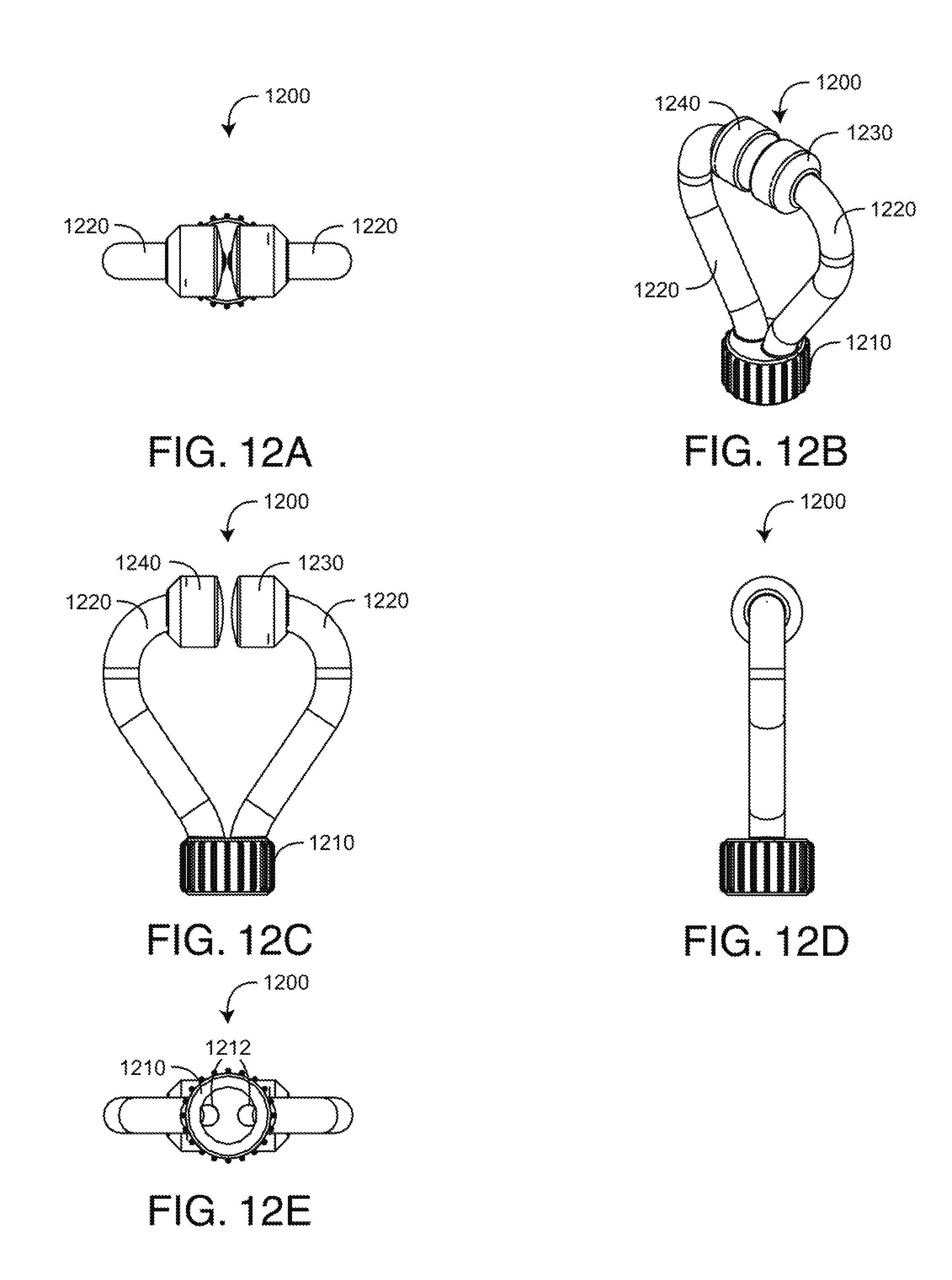
D00013
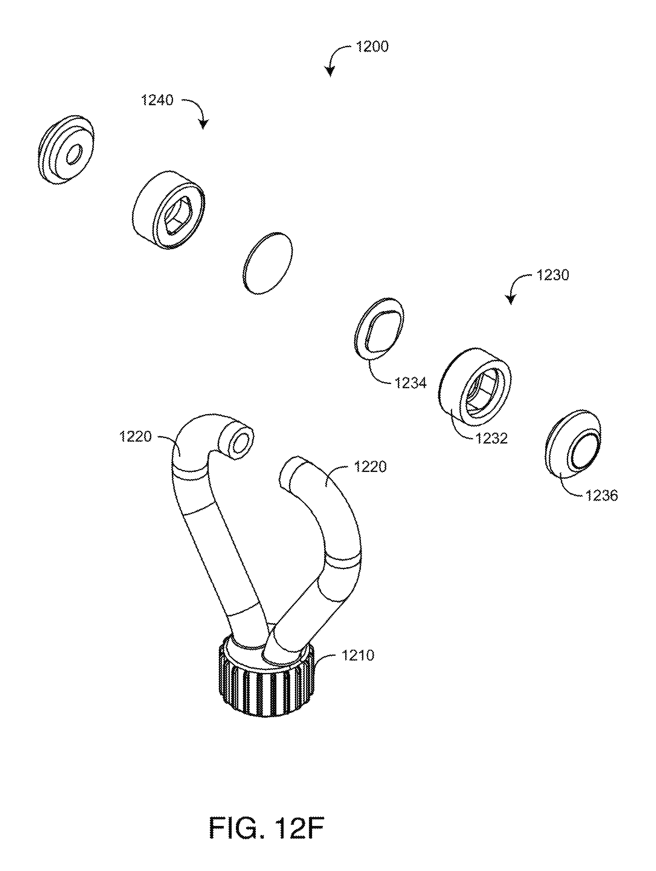
D00014

D00015

D00016
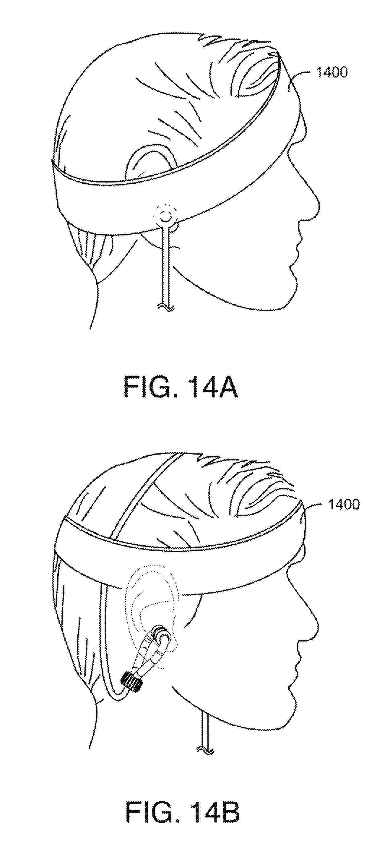
D00017

D00018

D00019

D00020

D00021

D00022

D00023

D00024

D00025
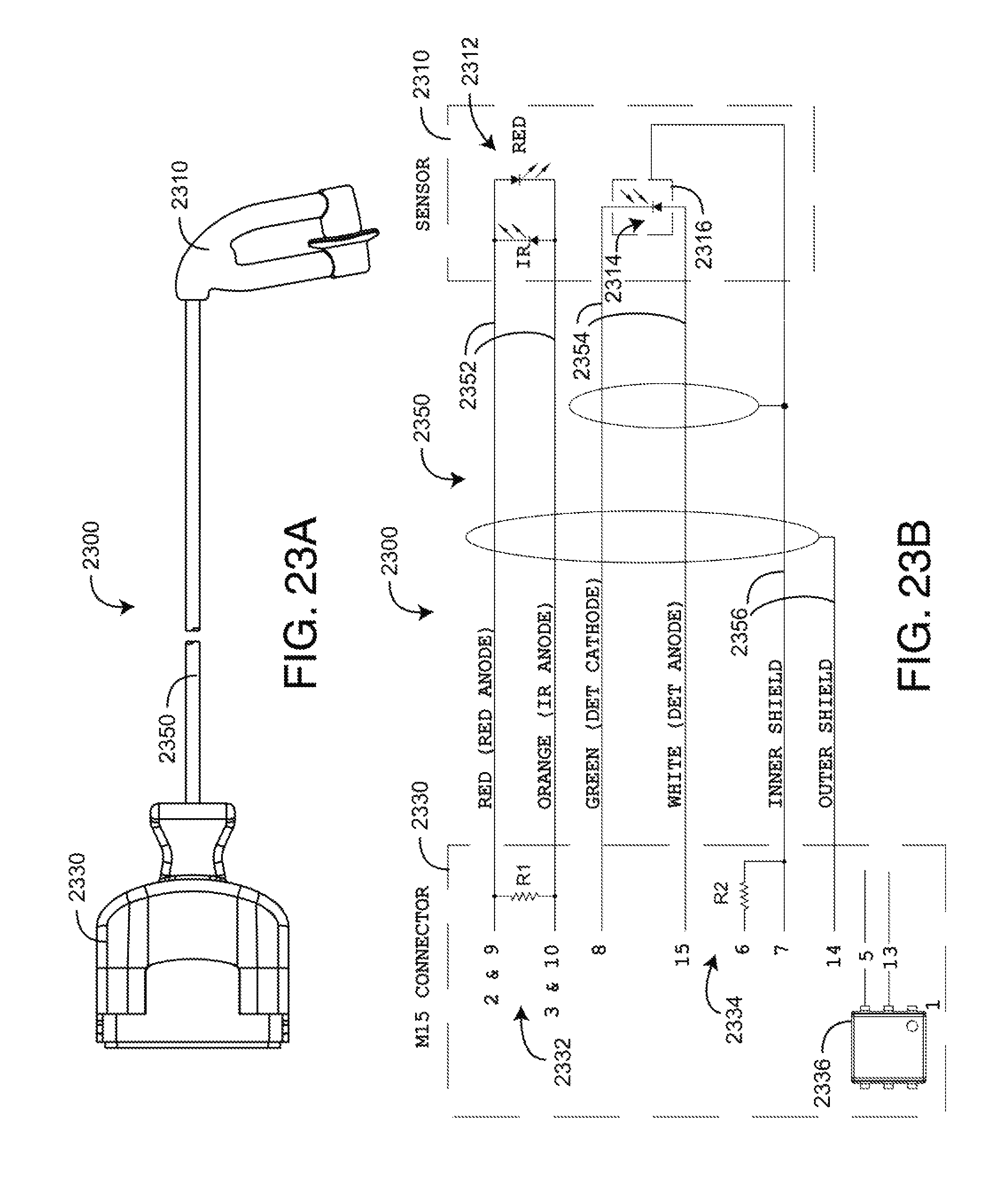
D00026

D00027

D00028

D00029

D00030

D00031
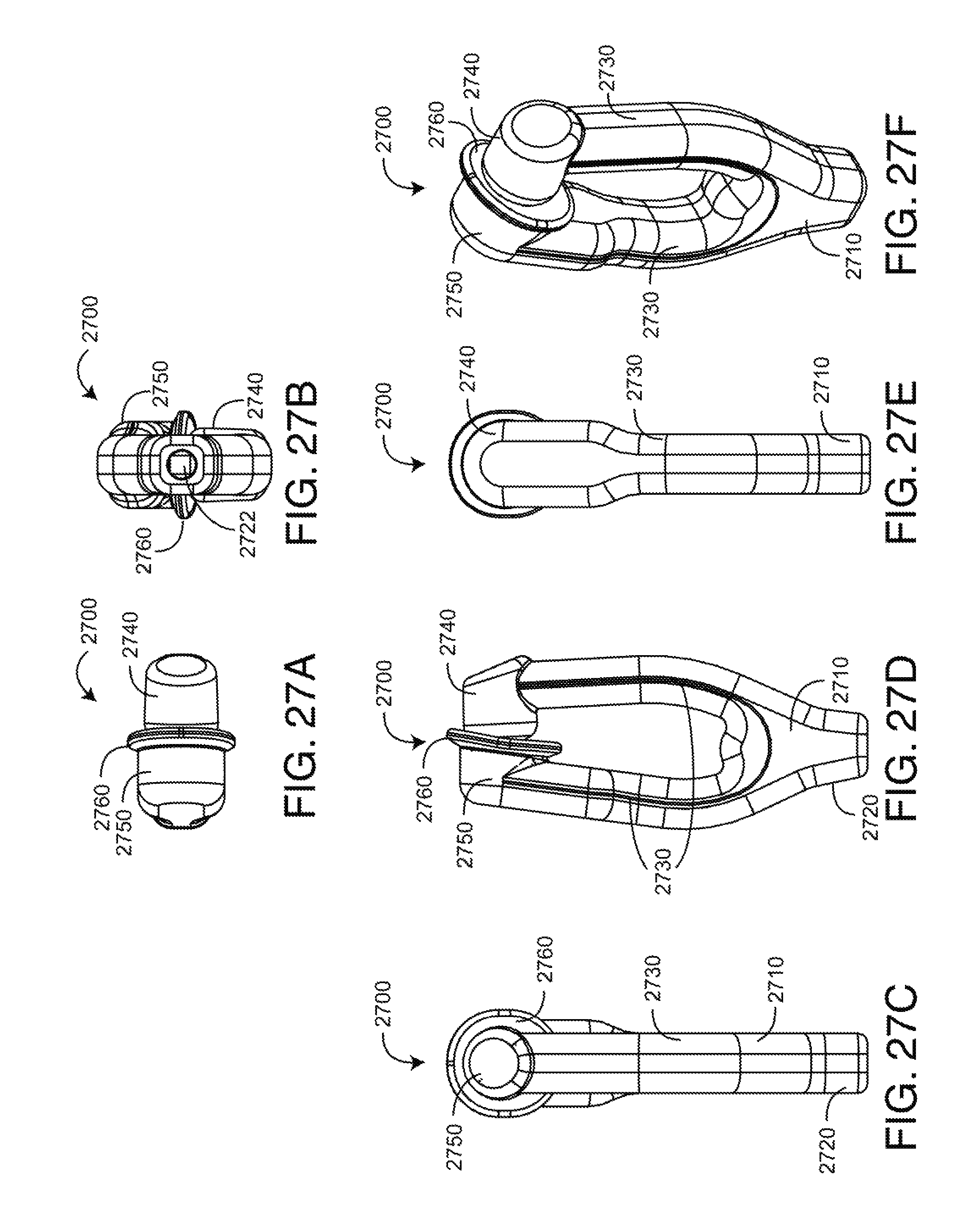
XML
uspto.report is an independent third-party trademark research tool that is not affiliated, endorsed, or sponsored by the United States Patent and Trademark Office (USPTO) or any other governmental organization. The information provided by uspto.report is based on publicly available data at the time of writing and is intended for informational purposes only.
While we strive to provide accurate and up-to-date information, we do not guarantee the accuracy, completeness, reliability, or suitability of the information displayed on this site. The use of this site is at your own risk. Any reliance you place on such information is therefore strictly at your own risk.
All official trademark data, including owner information, should be verified by visiting the official USPTO website at www.uspto.gov. This site is not intended to replace professional legal advice and should not be used as a substitute for consulting with a legal professional who is knowledgeable about trademark law.