TAVI anchoring assist device
Folan , et al.
U.S. patent number 10,285,809 [Application Number 15/060,258] was granted by the patent office on 2019-05-14 for tavi anchoring assist device. This patent grant is currently assigned to BOSTON SCIENTIFIC SCIMED INC.. The grantee listed for this patent is BOSTON SCIENTIFIC SCIMED, INC., Juan F. Granada. Invention is credited to Martyn G. Folan, Juan F. Granada.


View All Diagrams
| United States Patent | 10,285,809 |
| Folan , et al. | May 14, 2019 |
TAVI anchoring assist device
Abstract
An implant system may include a delivery sheath having an actuator mechanism, an anchoring assistance device including an expandable scaffold including a mid-body section, a cusp interface section, and a crown end arrangement, and a replacement heart valve implant. The cusp interface section includes a plurality of loop portions arranged at radial intervals about the expandable scaffold. Each loop portion is circumferentially spaced apart from another loop portion by a region having a deployment ring, the region being configured to span a commissure of the aortic valve and extending distally a shorter distance from the distal end than the loop portions. An elongate deployment member is configured to releasably engage with the deployment rings to actuate the expandable scaffold from a delivery configuration to a deployed configuration. The replacement heart valve implant is configured to be at least partially disposed within the expandable scaffold in the deployed configuration.
| Inventors: | Folan; Martyn G. (Galway, IE), Granada; Juan F. (Saddle River, NJ) | ||||||||||
|---|---|---|---|---|---|---|---|---|---|---|---|
| Applicant: |
|
||||||||||
| Assignee: | BOSTON SCIENTIFIC SCIMED INC.
(Maple Grove, MN) |
||||||||||
| Family ID: | 56849443 | ||||||||||
| Appl. No.: | 15/060,258 | ||||||||||
| Filed: | March 3, 2016 |
Prior Publication Data
| Document Identifier | Publication Date | |
|---|---|---|
| US 20160256270 A1 | Sep 8, 2016 | |
Related U.S. Patent Documents
| Application Number | Filing Date | Patent Number | Issue Date | ||
|---|---|---|---|---|---|
| 62129184 | Mar 6, 2015 | ||||
| 62204090 | Aug 12, 2015 | ||||
| Current U.S. Class: | 1/1 |
| Current CPC Class: | A61F 2/2418 (20130101); A61F 2/2409 (20130101); A61F 2/2436 (20130101); A61F 2/2439 (20130101); A61F 2230/0054 (20130101); A61F 2250/0003 (20130101); A61F 2250/0069 (20130101); A61F 2250/0037 (20130101); A61F 2250/006 (20130101) |
| Current International Class: | A61F 2/24 (20060101) |
References Cited [Referenced By]
U.S. Patent Documents
| 15192 | June 1856 | Peale |
| 2682057 | June 1954 | Lord |
| 2701559 | February 1955 | Cooper |
| 2832078 | April 1958 | Williams |
| 3099016 | July 1963 | Edwards |
| 3113586 | December 1963 | Edmark, Jr. |
| 3130418 | April 1964 | Head et al. |
| 3143742 | August 1964 | Cromie |
| 3334629 | August 1967 | Cohn |
| 3367364 | February 1968 | Cruz, Jr. et al. |
| 3409013 | November 1968 | Berry |
| 3445916 | May 1969 | Schulte |
| 3540431 | November 1970 | Mobin-Uddin |
| 3548417 | December 1970 | Kischer et al. |
| 3570014 | March 1971 | Hancock |
| 3587115 | June 1971 | Shiley |
| 3592184 | July 1971 | Watkins et al. |
| 3628535 | December 1971 | Ostrowsky et al. |
| 3642004 | February 1972 | Osthagen et al. |
| 3657744 | April 1972 | Ersek |
| 3671979 | June 1972 | Moulopoulos |
| 3714671 | February 1973 | Edwards et al. |
| 3755823 | September 1973 | Hancock |
| 3795246 | March 1974 | Sturgeon |
| 3839741 | October 1974 | Haller |
| 3868956 | March 1975 | Alfidi et al. |
| 3874388 | April 1975 | King et al. |
| 3997923 | December 1976 | Possis |
| 4035849 | July 1977 | Angell et al. |
| 4056854 | November 1977 | Boretos et al. |
| 4106129 | August 1978 | Carpentier et al. |
| 4222126 | September 1980 | Boretos et al. |
| 4233690 | November 1980 | Akins |
| 4265694 | May 1981 | Boretos et al. |
| 4291420 | September 1981 | Reul |
| 4297749 | November 1981 | Davis et al. |
| 4323358 | April 1982 | Lentz et al. |
| 4326306 | April 1982 | Poler |
| 4339831 | July 1982 | Johnson |
| 4343048 | August 1982 | Ross et al. |
| 4345340 | August 1982 | Rosen |
| 4373216 | February 1983 | Klawitter |
| 4406022 | September 1983 | Roy |
| 4423809 | January 1984 | Mazzocco |
| 4425908 | January 1984 | Simon |
| 4470157 | September 1984 | Love |
| 4484579 | November 1984 | Meno et al. |
| 4501030 | February 1985 | Lane |
| 4531943 | July 1985 | Van Tassel et al. |
| 4535483 | August 1985 | Klawitter et al. |
| 4574803 | March 1986 | Storz |
| 4580568 | April 1986 | Gianturco |
| 4592340 | June 1986 | Boyles |
| 4602911 | July 1986 | Ahmadi et al. |
| 4605407 | August 1986 | Black et al. |
| 4610688 | September 1986 | Silvestrini et al. |
| 4612011 | September 1986 | Kautzky |
| 4617932 | October 1986 | Kornberg |
| 4643732 | February 1987 | Pietsch et al. |
| 4647283 | March 1987 | Carpentier et al. |
| 4648881 | March 1987 | Carpentier et al. |
| 4655218 | April 1987 | Kulik et al. |
| 4655771 | April 1987 | Wallsten |
| 4662885 | May 1987 | Dipisa, Jr. |
| 4665906 | May 1987 | Jervis |
| 4680031 | July 1987 | Alonso |
| 4692164 | September 1987 | Dzemeshkevich et al. |
| 4705516 | November 1987 | Barone et al. |
| 4710192 | December 1987 | Liotta et al. |
| 4733665 | March 1988 | Palmaz |
| 4755181 | July 1988 | Igoe |
| 4759758 | July 1988 | Gabbay |
| 4777951 | October 1988 | Cribier et al. |
| 4787899 | November 1988 | Lazarus |
| 4787901 | November 1988 | Baykut |
| 4796629 | January 1989 | Grayzel |
| 4819751 | April 1989 | Shimada et al. |
| 4829990 | May 1989 | Thuroff et al. |
| 4834755 | May 1989 | Silvestrini et al. |
| 4851001 | July 1989 | Taheri |
| 4856516 | August 1989 | Hillstead |
| 4865600 | September 1989 | Carpentier et al. |
| 4872874 | October 1989 | Taheri |
| 4873978 | October 1989 | Ginsburg |
| 4878495 | November 1989 | Grayzel |
| 4878906 | November 1989 | Lindemann et al. |
| 4883458 | November 1989 | Shiber |
| 4885005 | December 1989 | Nashef et al. |
| 4909252 | March 1990 | Goldberger |
| 4917102 | April 1990 | Miller et al. |
| 4922905 | May 1990 | Strecker |
| 4927426 | May 1990 | Dretler |
| 4954126 | September 1990 | Wallsten |
| 4966604 | October 1990 | Reiss |
| 4969890 | November 1990 | Sugita et al. |
| 4979939 | December 1990 | Shiber |
| 4986830 | January 1991 | Owens et al. |
| 4994077 | February 1991 | Dobben |
| 5002556 | March 1991 | Ishida et al. |
| 5002559 | March 1991 | Tower |
| 5007896 | April 1991 | Shiber |
| 5026366 | June 1991 | Leckrone |
| 5032128 | July 1991 | Alonso |
| 5037434 | August 1991 | Lane |
| 5047041 | September 1991 | Samuels |
| 5064435 | November 1991 | Porter |
| 5080668 | January 1992 | Bolz et al. |
| 5085635 | February 1992 | Cragg |
| 5089015 | February 1992 | Ross |
| 5132473 | July 1992 | Furutaka et al. |
| 5141494 | August 1992 | Danforth et al. |
| 5152771 | October 1992 | Sabbaghian et al. |
| 5159937 | November 1992 | Tremulis |
| 5161547 | November 1992 | Tower |
| 5163953 | November 1992 | Vince |
| 5167628 | December 1992 | Boyles |
| 5209741 | May 1993 | Spaeth |
| 5215541 | June 1993 | Nashef et al. |
| 5217483 | June 1993 | Tower |
| 5238004 | August 1993 | Sahatjian et al. |
| 5258023 | November 1993 | Reger |
| 5258042 | November 1993 | Mehta |
| 5282847 | February 1994 | Trescony et al. |
| 5295958 | March 1994 | Shturman |
| 5332402 | July 1994 | Teitelbaum |
| 5336258 | August 1994 | Quintero et al. |
| 5350398 | September 1994 | Pavcnik et al. |
| 5360444 | November 1994 | Kusuhara |
| 5370685 | December 1994 | Stevens |
| 5389106 | February 1995 | Tower |
| 5397351 | March 1995 | Pavcnik et al. |
| 5409019 | April 1995 | Wilk |
| 5411552 | May 1995 | Andersen et al. |
| 5425762 | June 1995 | Muller |
| 5431676 | July 1995 | Dubrul et al. |
| 5443446 | August 1995 | Shturman |
| 5443449 | August 1995 | Buelna |
| 5443477 | August 1995 | Marin et al. |
| 5443495 | August 1995 | Buscemi et al. |
| 5443499 | August 1995 | Schmitt |
| 5476506 | December 1995 | Lunn |
| 5476510 | December 1995 | Eberhardt et al. |
| 5480423 | January 1996 | Ravenscroft et al. |
| 5480424 | January 1996 | Cox |
| 5500014 | March 1996 | Quijano et al. |
| 5507767 | April 1996 | Maeda et al. |
| 5534007 | July 1996 | St. Germain et al. |
| 5545133 | August 1996 | Bums et al. |
| 5545209 | August 1996 | Roberts et al. |
| 5545211 | August 1996 | An et al. |
| 5545214 | August 1996 | Stevens |
| 5549665 | August 1996 | Vesely et al. |
| 5554185 | September 1996 | Block et al. |
| 5571175 | November 1996 | Vanney et al. |
| 5571215 | November 1996 | Sterman et al. |
| 5573520 | November 1996 | Schwartz et al. |
| 5575818 | November 1996 | Pinchuk |
| 5591185 | January 1997 | Kilmer et al. |
| 5591195 | January 1997 | Taheri et al. |
| 5607464 | March 1997 | Trescony et al. |
| 5609626 | March 1997 | Quijano et al. |
| 5645559 | July 1997 | Hachtman et al. |
| 5662671 | September 1997 | Barbut et al. |
| 5667523 | September 1997 | Bynon et al. |
| 5674277 | October 1997 | Freitag |
| 5693083 | December 1997 | Baker et al. |
| 5693310 | December 1997 | Gries et al. |
| 5695498 | December 1997 | Tower |
| 5709713 | January 1998 | Evans et al. |
| 5713951 | February 1998 | Garrison et al. |
| 5713953 | February 1998 | Vallana et al. |
| 5716370 | February 1998 | Williamson, IV et al. |
| 5716417 | February 1998 | Girard et al. |
| 5720391 | February 1998 | Dohm et al. |
| 5725549 | March 1998 | Lam |
| 5728068 | March 1998 | Leone et al. |
| 5733325 | March 1998 | Robinson et al. |
| 5735842 | April 1998 | Krueger et al. |
| 5749890 | May 1998 | Shaknovich |
| 5755783 | May 1998 | Stobie et al. |
| 5756476 | May 1998 | Epstein et al. |
| 5769812 | June 1998 | Stevens et al. |
| 5772609 | June 1998 | Nguyen et al. |
| 5800456 | September 1998 | Maeda et al. |
| 5800531 | September 1998 | Cosgrove et al. |
| 5807405 | September 1998 | Vanney et al. |
| 5817126 | October 1998 | Imran |
| 5824041 | October 1998 | Lenker et al. |
| 5824043 | October 1998 | Cottone, Jr. |
| 5824053 | October 1998 | Khosravi et al. |
| 5824055 | October 1998 | Spiridigliozzi et al. |
| 5824056 | October 1998 | Rosenberg |
| 5824064 | October 1998 | Taheri |
| 5840081 | November 1998 | Andersen et al. |
| 5843158 | December 1998 | Lenker et al. |
| 5855597 | January 1999 | Jayaraman |
| 5855601 | January 1999 | Bessler et al. |
| 5855602 | January 1999 | Angell |
| 5860966 | January 1999 | Tower |
| 5861024 | January 1999 | Rashidi |
| 5861028 | January 1999 | Angell |
| 5868783 | February 1999 | Tower |
| 5876419 | March 1999 | Carpenter et al. |
| 5876448 | March 1999 | Thompson et al. |
| 5885228 | March 1999 | Rosenman et al. |
| 5888201 | March 1999 | Stinson et al. |
| 5891191 | April 1999 | Stinson |
| 5895399 | April 1999 | Barbut et al. |
| 5906619 | May 1999 | Olson et al. |
| 5907893 | June 1999 | Zadno-Azizi et al. |
| 5910154 | June 1999 | Tsugita et al. |
| 5911734 | June 1999 | Tsugita et al. |
| 5925063 | July 1999 | Khosravi |
| 5944738 | August 1999 | Amplatz et al. |
| 5954766 | September 1999 | Ladno-Azizi et al. |
| 5957949 | September 1999 | Leonhardt et al. |
| 5968070 | October 1999 | Bley et al. |
| 5984957 | November 1999 | Laptewicz, Jr. et al. |
| 5984959 | November 1999 | Robertson et al. |
| 5993469 | November 1999 | McKenzie et al. |
| 5997557 | December 1999 | Barbut et al. |
| 6010522 | January 2000 | Barbut et al. |
| 6022370 | February 2000 | Tower |
| 6027520 | February 2000 | Tsugita et al. |
| 6027525 | February 2000 | Suh et al. |
| 6042598 | March 2000 | Tsugita et al. |
| 6042607 | March 2000 | Williamson, IV et al. |
| 6051014 | April 2000 | Jang |
| 6059827 | May 2000 | Fenton, Jr. |
| 6074418 | June 2000 | Buchanan et al. |
| 6093203 | July 2000 | Uflacker |
| 6096074 | August 2000 | Pedros |
| 6123723 | September 2000 | Konya et al. |
| 6132473 | October 2000 | Williams et al. |
| 6139510 | October 2000 | Palermo |
| 6142987 | November 2000 | Tsugita |
| 6146366 | November 2000 | Schachar |
| 6162245 | December 2000 | Jayaraman |
| 6165200 | December 2000 | Tsugita et al. |
| 6165209 | December 2000 | Patterson et al. |
| 6168579 | January 2001 | Tsugita |
| 6168614 | January 2001 | Andersen et al. |
| 6171327 | January 2001 | Daniel et al. |
| 6171335 | January 2001 | Wheatley et al. |
| 6179859 | January 2001 | Bates et al. |
| 6187016 | February 2001 | Hedges et al. |
| 6197053 | March 2001 | Cosgrove et al. |
| 6200336 | March 2001 | Pavcnik et al. |
| 6214036 | April 2001 | Letendre et al. |
| 6221006 | April 2001 | Dubrul et al. |
| 6221091 | April 2001 | Khosravi |
| 6221096 | April 2001 | Aiba et al. |
| 6221100 | April 2001 | Strecker |
| 6231544 | May 2001 | Tsuigita et al. |
| 6231551 | May 2001 | Barbut |
| 6241757 | June 2001 | An et al. |
| 6245102 | June 2001 | Jayaraman |
| 6251135 | June 2001 | Stinson et al. |
| 6258114 | July 2001 | Konya et al. |
| 6258115 | July 2001 | Dubrul |
| 6258120 | July 2001 | McKenzie et al. |
| 6258129 | July 2001 | Dybdal et al. |
| 6267783 | July 2001 | Letendre et al. |
| 6270513 | August 2001 | Tsugita et al. |
| 6277555 | August 2001 | Duran et al. |
| 6299637 | October 2001 | Shaolian et al. |
| 6302906 | October 2001 | Goicoechea et al. |
| 6309417 | October 2001 | Spence et al. |
| 6319281 | November 2001 | Patel |
| 6327772 | December 2001 | Zadno-Azizi et al. |
| 6336934 | January 2002 | Gilson et al. |
| 6336937 | January 2002 | Vonesh et al. |
| 6338735 | January 2002 | Stevens |
| 6346116 | February 2002 | Brooks et al. |
| 6348063 | February 2002 | Yassour et al. |
| 6352554 | March 2002 | De Paulis |
| 6352708 | March 2002 | Duran et al. |
| 6361545 | March 2002 | Macoviak et al. |
| 6363938 | April 2002 | Saadat et al. |
| 6364895 | April 2002 | Greenhalgh |
| 6371970 | April 2002 | Khosravi et al. |
| 6371983 | April 2002 | Lane |
| 6379383 | April 2002 | Palmaz et al. |
| 6398807 | June 2002 | Chouinard et al. |
| 6402736 | June 2002 | Brown et al. |
| 6409750 | June 2002 | Hyodoh et al. |
| 6416510 | July 2002 | Altman et al. |
| 6425916 | July 2002 | Garrison et al. |
| 6440164 | August 2002 | DiMatteo et al. |
| 6454799 | September 2002 | Schreck |
| 6458153 | October 2002 | Bailey et al. |
| 6461382 | October 2002 | Cao |
| 6468303 | October 2002 | Amplatz et al. |
| 6468660 | October 2002 | Ogle et al. |
| 6475239 | November 2002 | Campbell et al. |
| 6482228 | November 2002 | Norred |
| 6485501 | November 2002 | Green |
| 6485502 | November 2002 | Don Michael et al. |
| 6488704 | December 2002 | Connelly et al. |
| 6494909 | December 2002 | Greenhalgh |
| 6503272 | January 2003 | Duerig et al. |
| 6508803 | January 2003 | Horikawa et al. |
| 6508833 | January 2003 | Pavcnik et al. |
| 6527800 | March 2003 | McGuckin, Jr. et al. |
| 6530949 | March 2003 | Konya et al. |
| 6530952 | March 2003 | Vesely |
| 6537297 | March 2003 | Tsugita et al. |
| 6540768 | April 2003 | Diaz et al. |
| 6562058 | May 2003 | Seguin et al. |
| 6569196 | May 2003 | Vesely |
| 6572643 | June 2003 | Gharibadeh |
| 6585766 | July 2003 | Huynh et al. |
| 6592546 | July 2003 | Barbut et al. |
| 6592614 | July 2003 | Lenker et al. |
| 6605112 | August 2003 | Moll et al. |
| 6610077 | August 2003 | Hancock et al. |
| 6616682 | September 2003 | Joergensen et al. |
| 6622604 | September 2003 | Chouinard et al. |
| 6623518 | September 2003 | Thompson et al. |
| 6623521 | September 2003 | Steinke et al. |
| 6632243 | October 2003 | Zadno-Azizi et al. |
| 6635068 | October 2003 | Dubrul et al. |
| 6635079 | October 2003 | Unsworth et al. |
| 6652571 | November 2003 | White et al. |
| 6652578 | November 2003 | Bailey et al. |
| 6663588 | December 2003 | Dubois et al. |
| 6663663 | December 2003 | Kim et al. |
| 6669724 | December 2003 | Park et al. |
| 6673089 | January 2004 | Yassour et al. |
| 6673109 | January 2004 | Cox |
| 6676668 | January 2004 | Mercereau et al. |
| 6676692 | January 2004 | Rabkin et al. |
| 6676698 | January 2004 | McGuckin, Jr. et al. |
| 6682543 | January 2004 | Barbut et al. |
| 6682558 | January 2004 | Tu et al. |
| 6682559 | January 2004 | Myers et al. |
| 6685739 | February 2004 | DiMatteo et al. |
| 6689144 | February 2004 | Gerberding |
| 6689164 | February 2004 | Seguin |
| 6692512 | February 2004 | Jang |
| 6695864 | February 2004 | Macoviak et al. |
| 6695865 | February 2004 | Boyle et al. |
| 6702851 | March 2004 | Chinn et al. |
| 6712842 | March 2004 | Gifford, III et al. |
| 6712843 | March 2004 | Elliott |
| 6714842 | March 2004 | Ito |
| 6719789 | April 2004 | Cox |
| 6723116 | April 2004 | Taheri |
| 6730118 | May 2004 | Spenser et al. |
| 6730377 | May 2004 | Wang |
| 6733525 | May 2004 | Yang et al. |
| 6736846 | May 2004 | Cox |
| 6752828 | June 2004 | Thornton |
| 6755854 | June 2004 | Gillick et al. |
| 6758855 | July 2004 | Fulton, III et al. |
| 6764503 | July 2004 | Ishimaru |
| 6764509 | July 2004 | Chinn et al. |
| 6767345 | July 2004 | St. Germain et al. |
| 6769434 | August 2004 | Liddicoat et al. |
| 6773454 | August 2004 | Wholey et al. |
| 6776791 | August 2004 | Stallings et al. |
| 6786925 | September 2004 | Schoon et al. |
| 6790229 | September 2004 | Berreklouw |
| 6790230 | September 2004 | Beyersdorf et al. |
| 6790237 | September 2004 | Stinson |
| 6792979 | September 2004 | Konya et al. |
| 6797002 | September 2004 | Spence et al. |
| 6814746 | November 2004 | Thompson et al. |
| 6821297 | November 2004 | Snyders |
| 6830585 | December 2004 | Artof et al. |
| 6837901 | January 2005 | Rabkin et al. |
| 6840957 | January 2005 | DiMatteo et al. |
| 6843802 | January 2005 | Villalobos et al. |
| 6849085 | February 2005 | Marton |
| 6863668 | March 2005 | Gillespie et al. |
| 6866650 | March 2005 | Stevens et al. |
| 6866669 | March 2005 | Buzzard et al. |
| 6872223 | March 2005 | Roberts et al. |
| 6872226 | March 2005 | Cali et al. |
| 6875231 | April 2005 | Anduiza et al. |
| 6881220 | April 2005 | Edwin et al. |
| 6887266 | May 2005 | Williams et al. |
| 6890340 | May 2005 | Duane |
| 6893459 | May 2005 | Macoviak |
| 6893460 | May 2005 | Spenser et al. |
| 6905743 | June 2005 | Chen et al. |
| 6908481 | June 2005 | Cribier |
| 6911036 | June 2005 | Douk et al. |
| 6911043 | June 2005 | Myers et al. |
| 6936058 | August 2005 | Forde et al. |
| 6936067 | August 2005 | Buchanan |
| 6939352 | September 2005 | Buzzard et al. |
| 6951571 | October 2005 | Srivastava |
| 6953332 | October 2005 | Kurk et al. |
| 6964673 | November 2005 | Tsugita et al. |
| 6969395 | November 2005 | Eskuri |
| 6972025 | December 2005 | WasDyke |
| 6974464 | December 2005 | Quijano et al. |
| 6974474 | December 2005 | Pavcnik et al. |
| 6974476 | December 2005 | McGuckin, Jr. et al. |
| 6979350 | December 2005 | Moll et al. |
| 6984242 | January 2006 | Campbell et al. |
| 6989027 | January 2006 | Allen et al. |
| 7004176 | February 2006 | Lau |
| 7011681 | March 2006 | Vesely |
| 7018406 | March 2006 | Seguin et al. |
| 7025791 | April 2006 | Levine et al. |
| 7037331 | May 2006 | Mitelberg et al. |
| 7041132 | May 2006 | Quijano et al. |
| 7097658 | August 2006 | Oktay |
| 7122020 | October 2006 | Mogul |
| 7125418 | October 2006 | Duran et al. |
| 7141063 | November 2006 | White et al. |
| 7166097 | January 2007 | Barbut |
| 7175653 | February 2007 | Gaber |
| 7175654 | February 2007 | Bonsignore et al. |
| 7175656 | February 2007 | Khairkhahan |
| 7189258 | March 2007 | Johnson et al. |
| 7191018 | March 2007 | Gielen et al. |
| 7201772 | April 2007 | Schwammenthal et al. |
| 7235093 | June 2007 | Gregorich |
| 7258696 | August 2007 | Rabkin et al. |
| 7267686 | September 2007 | DiMatteo et al. |
| 7276078 | October 2007 | Spenser et al. |
| 7322932 | January 2008 | Xie et al. |
| 7326236 | February 2008 | Andreas et al. |
| 7329279 | February 2008 | Haug et al. |
| 7374560 | May 2008 | Ressemann et al. |
| 7381219 | June 2008 | Salahieh et al. |
| 7381220 | June 2008 | Macoviak et al. |
| 7399315 | July 2008 | Iobbi |
| 7445631 | November 2008 | Salahieh et al. |
| 7470285 | December 2008 | Nugent et al. |
| 7491232 | February 2009 | Bolduc et al. |
| 7510574 | March 2009 | L et al. |
| 7524330 | April 2009 | Berreklouw |
| 7530995 | May 2009 | Quijano et al. |
| 7544206 | June 2009 | Cohn |
| 7622276 | November 2009 | Cunanan et al. |
| 7628803 | December 2009 | Pavcnik et al. |
| 7632298 | December 2009 | Hijlkema et al. |
| 7674282 | March 2010 | Wu et al. |
| 7712606 | May 2010 | Salahieh et al. |
| 7722638 | May 2010 | Deyette, Jr. et al. |
| 7722662 | May 2010 | Steinke et al. |
| 7722666 | May 2010 | Lafontaine |
| 7736388 | June 2010 | Goldfarb et al. |
| 7748389 | July 2010 | Salahieh et al. |
| 7758625 | July 2010 | Wu et al. |
| 7780725 | August 2010 | Haug et al. |
| 7799065 | September 2010 | Pappas |
| 7803185 | September 2010 | Gabbay |
| 7824442 | November 2010 | Salahieh et al. |
| 7824443 | November 2010 | Salahieh et al. |
| 7833262 | November 2010 | McGuckin, Jr. et al. |
| 7846204 | December 2010 | Letac et al. |
| 7892292 | February 2011 | Stack et al. |
| 7918880 | April 2011 | Austin |
| 7938851 | May 2011 | Olson et al. |
| 7959666 | June 2011 | Salahieh et al. |
| 7959672 | June 2011 | Salahieh et al. |
| 7988724 | August 2011 | Salahieh et al. |
| 8048153 | November 2011 | Salahieh et al. |
| 8052749 | November 2011 | Salahieh et al. |
| 8136659 | March 2012 | Salahieh et al. |
| 8157853 | April 2012 | Laske et al. |
| 8182528 | May 2012 | Salahieh et al. |
| 8192351 | June 2012 | Fishler et al. |
| 8226710 | July 2012 | Nguyen et al. |
| 8231670 | July 2012 | Salahieh et al. |
| 8236049 | August 2012 | Rowe et al. |
| 8246678 | August 2012 | Salahieh et al. |
| 8252051 | August 2012 | Chau et al. |
| 8252052 | August 2012 | Salahieh et al. |
| 8287584 | October 2012 | Salahieh et al. |
| 8308798 | November 2012 | Pintor et al. |
| 8323335 | December 2012 | Rowe et al. |
| 8328868 | December 2012 | Paul et al. |
| 8343213 | January 2013 | Salahieh et al. |
| 8376865 | February 2013 | Forster et al. |
| 8377117 | February 2013 | Keidar et al. |
| 8398708 | March 2013 | Meiri et al. |
| 8579962 | November 2013 | Salahieh et al. |
| 8603160 | December 2013 | Salahieh et al. |
| 8617236 | December 2013 | Paul et al. |
| 8623074 | January 2014 | Ryan |
| 8623076 | January 2014 | Salahieh et al. |
| 8623078 | January 2014 | Salahieh et al. |
| 8668733 | March 2014 | Haug et al. |
| RE45130 | September 2014 | Figulla |
| 8828078 | September 2014 | Salahieh et al. |
| 8840662 | September 2014 | Salahieh et al. |
| 8840663 | September 2014 | Salahieh et al. |
| 8858620 | October 2014 | Salahieh et al. |
| 2001/0002445 | May 2001 | Vesely |
| 2001/0007956 | July 2001 | Letac et al. |
| 2001/0010017 | July 2001 | Letac et al. |
| 2001/0021872 | September 2001 | Bailey et al. |
| 2001/0025196 | September 2001 | Chinn et al. |
| 2001/0032013 | October 2001 | Marton |
| 2001/0039450 | November 2001 | Pavcnik et al. |
| 2001/0041928 | November 2001 | Pavcnik et al. |
| 2001/0041930 | November 2001 | Globerman et al. |
| 2001/0044634 | November 2001 | Don Michael et al. |
| 2001/0044652 | November 2001 | Moore |
| 2001/0044656 | November 2001 | Williamson, IV et al. |
| 2002/0002396 | January 2002 | Fulkerson |
| 2002/0010489 | January 2002 | Grayzel et al. |
| 2002/0026233 | February 2002 | Shaknovich |
| 2002/0029014 | March 2002 | Jayaraman |
| 2002/0029981 | March 2002 | Nigam |
| 2002/0032480 | March 2002 | Spence et al. |
| 2002/0032481 | March 2002 | Gabbay |
| 2002/0042651 | April 2002 | Liddicoat et al. |
| 2002/0052651 | May 2002 | Myers et al. |
| 2002/0055767 | May 2002 | Forde et al. |
| 2002/0055769 | May 2002 | Wang |
| 2002/0058995 | May 2002 | Stevens |
| 2002/0077696 | June 2002 | Zadno-Azizi et al. |
| 2002/0082609 | June 2002 | Green |
| 2002/0095173 | July 2002 | Mazzocchi |
| 2002/0095209 | July 2002 | Zadno-Azizi et al. |
| 2002/0111674 | August 2002 | Chouinard et al. |
| 2002/0120328 | August 2002 | Pathak et al. |
| 2002/0123802 | September 2002 | Snyders |
| 2002/0138138 | September 2002 | Yang |
| 2002/0151970 | October 2002 | Garrison et al. |
| 2002/0161390 | October 2002 | Mouw |
| 2002/0161392 | October 2002 | Dubrul |
| 2002/0161394 | October 2002 | Macoviak et al. |
| 2002/0165576 | November 2002 | Boyle et al. |
| 2002/0177766 | November 2002 | Mogul |
| 2002/0183781 | December 2002 | Casey et al. |
| 2002/0188341 | December 2002 | Elliott |
| 2002/0188344 | December 2002 | Bolea et al. |
| 2002/0193871 | December 2002 | Beyersdorf et al. |
| 2003/0014104 | January 2003 | Cribier |
| 2003/0023303 | January 2003 | Palmaz et al. |
| 2003/0028247 | February 2003 | Cali |
| 2003/0036791 | February 2003 | Philipp et al. |
| 2003/0040736 | February 2003 | Stevens et al. |
| 2003/0040771 | February 2003 | Hyodoh et al. |
| 2003/0040772 | February 2003 | Hyodoh et al. |
| 2003/0040791 | February 2003 | Oktay |
| 2003/0040792 | February 2003 | Gabbay |
| 2003/0050694 | March 2003 | Yang et al. |
| 2003/0055495 | March 2003 | Pease et al. |
| 2003/0057156 | March 2003 | Peterson et al. |
| 2003/0060844 | March 2003 | Borillo et al. |
| 2003/0069492 | April 2003 | Abrams et al. |
| 2003/0069646 | April 2003 | Stinson |
| 2003/0070944 | April 2003 | Nigam |
| 2003/0100918 | May 2003 | Duane |
| 2003/0100919 | May 2003 | Hopkins et al. |
| 2003/0109924 | June 2003 | Cribier |
| 2003/0109930 | June 2003 | Bluni et al. |
| 2003/0114912 | June 2003 | Sequin et al. |
| 2003/0114913 | June 2003 | Spenser et al. |
| 2003/0125795 | July 2003 | Pavcnik et al. |
| 2003/0130729 | July 2003 | Paniagua et al. |
| 2003/0135257 | July 2003 | Taheri |
| 2003/0144732 | July 2003 | Cosgrove et al. |
| 2003/0149475 | August 2003 | Hyodoh et al. |
| 2003/0149476 | August 2003 | Damm et al. |
| 2003/0149478 | August 2003 | Figulla et al. |
| 2003/0153974 | August 2003 | Spenser et al. |
| 2003/0171803 | September 2003 | Shimon |
| 2003/0176884 | September 2003 | Berrada et al. |
| 2003/0181850 | September 2003 | Diamond et al. |
| 2003/0187495 | October 2003 | Cully et al. |
| 2003/0191516 | October 2003 | Weldon et al. |
| 2003/0195609 | October 2003 | Berenstein et al. |
| 2003/0199759 | October 2003 | Richard |
| 2003/0199913 | October 2003 | Dubrul et al. |
| 2003/0199971 | October 2003 | Tower et al. |
| 2003/0199972 | October 2003 | Zadno-Azizi et al. |
| 2003/0208224 | November 2003 | Broome |
| 2003/0212429 | November 2003 | Keegan et al. |
| 2003/0212452 | November 2003 | Zadno-Azizi et al. |
| 2003/0212454 | November 2003 | Scott et al. |
| 2003/0216774 | November 2003 | Larson |
| 2003/0225445 | December 2003 | Derus et al. |
| 2003/0229390 | December 2003 | Ashton et al. |
| 2003/0233117 | December 2003 | Adams et al. |
| 2004/0019374 | January 2004 | Hojeibane et al. |
| 2004/0034411 | February 2004 | Quijano et al. |
| 2004/0039436 | February 2004 | Spenser et al. |
| 2004/0049224 | March 2004 | Buehlmann et al. |
| 2004/0049226 | March 2004 | Keegan et al. |
| 2004/0049262 | March 2004 | Obermiller et al. |
| 2004/0049266 | March 2004 | Anduiza et al. |
| 2004/0059409 | March 2004 | Stenzel |
| 2004/0073198 | April 2004 | Gilson et al. |
| 2004/0082904 | April 2004 | Houde et al. |
| 2004/0082967 | April 2004 | Broome et al. |
| 2004/0087982 | May 2004 | Eskuri |
| 2004/0088045 | May 2004 | Cox |
| 2004/0093016 | May 2004 | Root et al. |
| 2004/0093060 | May 2004 | Seguin et al. |
| 2004/0097788 | May 2004 | Mourlas et al. |
| 2004/0098022 | May 2004 | Barone |
| 2004/0098098 | May 2004 | McGuckin, Jr. et al. |
| 2004/0098099 | May 2004 | McCullagh et al. |
| 2004/0098112 | May 2004 | DiMatteo et al. |
| 2004/0107004 | June 2004 | Levine et al. |
| 2004/0111096 | June 2004 | Tu et al. |
| 2004/0116951 | June 2004 | Rosengart |
| 2004/0117004 | June 2004 | Osborne et al. |
| 2004/0117009 | June 2004 | Cali et al. |
| 2004/0122468 | June 2004 | Yodfat et al. |
| 2004/0122516 | June 2004 | Fogarty et al. |
| 2004/0127936 | July 2004 | Salahieh et al. |
| 2004/0127979 | July 2004 | Wilson et al. |
| 2004/0133274 | July 2004 | Webler et al. |
| 2004/0138694 | July 2004 | Tran et al. |
| 2004/0138742 | July 2004 | Myers et al. |
| 2004/0138743 | July 2004 | Myers et al. |
| 2004/0148018 | July 2004 | Carpentier et al. |
| 2004/0148021 | July 2004 | Cartledge et al. |
| 2004/0153094 | August 2004 | Dunfee et al. |
| 2004/0158277 | August 2004 | Lowe et al. |
| 2004/0167565 | August 2004 | Beulke et al. |
| 2004/0167620 | August 2004 | Ortiz et al. |
| 2004/0181140 | September 2004 | Falwell et al. |
| 2004/0186558 | September 2004 | Pavcnik et al. |
| 2004/0186563 | September 2004 | Lobbi |
| 2004/0193261 | September 2004 | Berreklouw |
| 2004/0199245 | October 2004 | Lauterjung |
| 2004/0204755 | October 2004 | Robin |
| 2004/0210304 | October 2004 | Seguin et al. |
| 2004/0210306 | October 2004 | Quijano et al. |
| 2004/0210307 | October 2004 | Khairkhahan |
| 2004/0215331 | October 2004 | Chew et al. |
| 2004/0215333 | October 2004 | Duran et al. |
| 2004/0215339 | October 2004 | Drasler et al. |
| 2004/0220655 | November 2004 | Swanson et al. |
| 2004/0225321 | November 2004 | Krolik et al. |
| 2004/0225353 | November 2004 | McGuckin, Jr. et al. |
| 2004/0225354 | November 2004 | Allen et al. |
| 2004/0225355 | November 2004 | Stevens |
| 2004/0243221 | December 2004 | Fawzi et al. |
| 2004/0254636 | December 2004 | Flagle et al. |
| 2004/0260390 | December 2004 | Sarac et al. |
| 2005/0010287 | January 2005 | Macoviak et al. |
| 2005/0021136 | January 2005 | Xie et al. |
| 2005/0033398 | February 2005 | Seguin |
| 2005/0033402 | February 2005 | Cully et al. |
| 2005/0043711 | February 2005 | Corcoran et al. |
| 2005/0043757 | February 2005 | Arad et al. |
| 2005/0043790 | February 2005 | Seguin |
| 2005/0049692 | March 2005 | Numamoto et al. |
| 2005/0049696 | March 2005 | Siess et al. |
| 2005/0055088 | March 2005 | Liddicoat et al. |
| 2005/0060016 | March 2005 | Wu et al. |
| 2005/0060029 | March 2005 | Le et al. |
| 2005/0065594 | March 2005 | DiMatteo et al. |
| 2005/0075584 | April 2005 | Cali |
| 2005/0075662 | April 2005 | Pedersen et al. |
| 2005/0075712 | April 2005 | Biancucci et al. |
| 2005/0075717 | April 2005 | Nguyen et al. |
| 2005/0075719 | April 2005 | Bergheim |
| 2005/0075724 | April 2005 | Svanidze et al. |
| 2005/0075730 | April 2005 | Myers et al. |
| 2005/0075731 | April 2005 | Artof et al. |
| 2005/0085841 | April 2005 | Eversull et al. |
| 2005/0085842 | April 2005 | Eversull et al. |
| 2005/0085843 | April 2005 | Opolski et al. |
| 2005/0085890 | April 2005 | Rasmussen et al. |
| 2005/0090846 | April 2005 | Pedersen et al. |
| 2005/0090890 | April 2005 | Wu et al. |
| 2005/0096692 | May 2005 | Linder et al. |
| 2005/0096734 | May 2005 | Majercak et al. |
| 2005/0096735 | May 2005 | Hojeibane et al. |
| 2005/0096736 | May 2005 | Osse et al. |
| 2005/0096738 | May 2005 | Cali et al. |
| 2005/0100580 | May 2005 | Osborne et al. |
| 2005/0107822 | May 2005 | Wasdyke |
| 2005/0113910 | May 2005 | Paniagua et al. |
| 2005/0131438 | June 2005 | Cohn |
| 2005/0137683 | June 2005 | Hezi-Yamit et al. |
| 2005/0137686 | June 2005 | Salahieh et al. |
| 2005/0137687 | June 2005 | Salahieh et al. |
| 2005/0137688 | June 2005 | Salahieh et al. |
| 2005/0137689 | June 2005 | Salahieh et al. |
| 2005/0137690 | June 2005 | Salahieh et al. |
| 2005/0137691 | June 2005 | Salahieh et al. |
| 2005/0137692 | June 2005 | Haug et al. |
| 2005/0137693 | June 2005 | Haug et al. |
| 2005/0137694 | June 2005 | Haug et al. |
| 2005/0137695 | June 2005 | Salahieh et al. |
| 2005/0137696 | June 2005 | Salahieh et al. |
| 2005/0137697 | June 2005 | Salahieh et al. |
| 2005/0137698 | June 2005 | Salahieh et al. |
| 2005/0137699 | June 2005 | Salahieh et al. |
| 2005/0137701 | June 2005 | Salahieh et al. |
| 2005/0137702 | June 2005 | Haug et al. |
| 2005/0143807 | June 2005 | Pavcnik et al. |
| 2005/0143809 | June 2005 | Salahieh et al. |
| 2005/0149159 | July 2005 | Andreas et al. |
| 2005/0165352 | July 2005 | Henry et al. |
| 2005/0165477 | July 2005 | Anduiza et al. |
| 2005/0165479 | July 2005 | Drews et al. |
| 2005/0182486 | August 2005 | Gabbay |
| 2005/0197694 | September 2005 | Pai et al. |
| 2005/0197695 | September 2005 | Stacchino et al. |
| 2005/0203549 | September 2005 | Realyvasquez |
| 2005/0203614 | September 2005 | Forster et al. |
| 2005/0203615 | September 2005 | Forster et al. |
| 2005/0203616 | September 2005 | Cribier |
| 2005/0203617 | September 2005 | Forster et al. |
| 2005/0203618 | September 2005 | Sharkawy et al. |
| 2005/0209580 | September 2005 | Freyman |
| 2005/0228472 | October 2005 | Case et al. |
| 2005/0228495 | October 2005 | Macoviak |
| 2005/0234546 | October 2005 | Nugent et al. |
| 2005/0240200 | October 2005 | Bergheim |
| 2005/0240262 | October 2005 | White |
| 2005/0251250 | November 2005 | Verhoeven et al. |
| 2005/0251251 | November 2005 | Cribier |
| 2005/0261759 | November 2005 | Lambrecht et al. |
| 2005/0267560 | December 2005 | Bates |
| 2005/0283231 | December 2005 | Haug et al. |
| 2005/0283962 | December 2005 | Boudjemline |
| 2006/0004439 | January 2006 | Spenser et al. |
| 2006/0004442 | January 2006 | Spenser et al. |
| 2006/0015168 | January 2006 | Gunderson |
| 2006/0058872 | March 2006 | Salahieh et al. |
| 2006/0149360 | July 2006 | Schwammenthal et al. |
| 2006/0155312 | July 2006 | Levine et al. |
| 2006/0161249 | July 2006 | Realyvasquez et al. |
| 2006/0173524 | August 2006 | Salahieh et al. |
| 2006/0195183 | August 2006 | Navia et al. |
| 2006/0253191 | November 2006 | Salahieh et al. |
| 2006/0259134 | November 2006 | Schwammenthal et al. |
| 2006/0271166 | November 2006 | Thill et al. |
| 2006/0287668 | December 2006 | Fawzi et al. |
| 2006/0287717 | December 2006 | Rowe et al. |
| 2007/0010876 | January 2007 | Salahieh et al. |
| 2007/0010877 | January 2007 | Salahieh et al. |
| 2007/0016286 | January 2007 | Herrmann et al. |
| 2007/0055340 | March 2007 | Pryor |
| 2007/0061008 | March 2007 | Salahieh et al. |
| 2007/0112355 | May 2007 | Salahieh et al. |
| 2007/0118214 | May 2007 | Salahieh et al. |
| 2007/0162107 | July 2007 | Haug et al. |
| 2007/0173918 | July 2007 | Dreher et al. |
| 2007/0203503 | August 2007 | Salahieh et al. |
| 2007/0244552 | October 2007 | Salahieh et al. |
| 2007/0288089 | December 2007 | Gurskis et al. |
| 2008/0009940 | January 2008 | Cribier |
| 2008/0033541 | February 2008 | Gelbart et al. |
| 2008/0082165 | April 2008 | Wilson et al. |
| 2008/0125859 | May 2008 | Salahieh et al. |
| 2008/0188928 | August 2008 | Salahieh et al. |
| 2008/0208328 | August 2008 | Antocci et al. |
| 2008/0208332 | August 2008 | Lamphere et al. |
| 2008/0221672 | September 2008 | Lamphere et al. |
| 2008/0234814 | September 2008 | Salahieh et al. |
| 2008/0255661 | October 2008 | Straubinger et al. |
| 2008/0269878 | October 2008 | Iobbi |
| 2008/0288054 | November 2008 | Pulnev et al. |
| 2009/0005863 | January 2009 | Goetz et al. |
| 2009/0030512 | January 2009 | Thielen et al. |
| 2009/0054969 | February 2009 | Salahieh et al. |
| 2009/0076598 | March 2009 | Salahieh et al. |
| 2009/0093877 | April 2009 | Keidar et al. |
| 2009/0171456 | July 2009 | Kveen et al. |
| 2009/0222076 | September 2009 | Figulla et al. |
| 2009/0264759 | October 2009 | Byrd |
| 2009/0264997 | October 2009 | Salahieh et al. |
| 2009/0299462 | December 2009 | Fawzi et al. |
| 2010/0049313 | February 2010 | Alon et al. |
| 2010/0094399 | April 2010 | Dorn et al. |
| 2010/0121434 | May 2010 | Paul et al. |
| 2010/0168839 | July 2010 | Braido et al. |
| 2010/0191326 | July 2010 | Alkhatib |
| 2010/0219092 | September 2010 | Salahieh et al. |
| 2010/0280495 | November 2010 | Paul et al. |
| 2011/0257735 | October 2011 | Salahieh et al. |
| 2011/0276129 | November 2011 | Salahieh et al. |
| 2012/0016469 | January 2012 | Salahieh et al. |
| 2012/0016471 | January 2012 | Salahieh et al. |
| 2012/0022642 | January 2012 | Haug et al. |
| 2012/0029627 | February 2012 | Salahieh et al. |
| 2012/0041549 | February 2012 | Salahieh et al. |
| 2012/0041550 | February 2012 | Salahieh et al. |
| 2012/0046740 | February 2012 | Paul et al. |
| 2012/0053683 | March 2012 | Salahieh et al. |
| 2012/0089224 | April 2012 | Haug et al. |
| 2012/0132547 | May 2012 | Salahieh et al. |
| 2012/0197379 | August 2012 | Laske et al. |
| 2012/0330409 | December 2012 | Haug et al. |
| 2013/0013057 | January 2013 | Salahieh et al. |
| 2013/0018457 | January 2013 | Gregg et al. |
| 2013/0030520 | January 2013 | Lee et al. |
| 2013/0123796 | May 2013 | Sutton et al. |
| 2013/0158656 | June 2013 | Sutton et al. |
| 2013/0190865 | July 2013 | Anderson |
| 2013/0304199 | November 2013 | Sutton et al. |
| 2014/0018911 | January 2014 | Zhou et al. |
| 2014/0094904 | April 2014 | Salahieh et al. |
| 2014/0114405 | April 2014 | Paul et al. |
| 2014/0114406 | April 2014 | Salahieh et al. |
| 2014/0121766 | May 2014 | Salahieh et al. |
| 2014/0135912 | May 2014 | Salahieh et al. |
| 2014/0236289 | August 2014 | Alkhatib |
| 2014/0243967 | August 2014 | Salahieh et al. |
| 2014/0249621 | September 2014 | Eidenschink |
| 2015/0032206 | January 2015 | Alkhatib |
| 2015/0265400 | September 2015 | Eidenschink |
| 1338951 | Mar 2002 | CN | |||
| 19532846 | Mar 1997 | DE | |||
| 19546692 | Jun 1997 | DE | |||
| 19857887 | Jul 2000 | DE | |||
| 19907646 | Aug 2000 | DE | |||
| 10049812 | Apr 2002 | DE | |||
| 10049813 | Apr 2002 | DE | |||
| 10049814 | Apr 2002 | DE | |||
| 10049815 | Apr 2002 | DE | |||
| 0103546 | May 1988 | EP | |||
| 0144167 | Nov 1989 | EP | |||
| 0409929 | Apr 1997 | EP | |||
| 0850607 | Jul 1998 | EP | |||
| 0597967 | Dec 1999 | EP | |||
| 1000590 | May 2000 | EP | |||
| 1057459 | Dec 2000 | EP | |||
| 1057460 | Dec 2000 | EP | |||
| 1088529 | Apr 2001 | EP | |||
| 0937439 | Sep 2003 | EP | |||
| 1340473 | Sep 2003 | EP | |||
| 1356793 | Oct 2003 | EP | |||
| 1042045 | May 2004 | EP | |||
| 0819013 | Jun 2004 | EP | |||
| 1430853 | Jun 2004 | EP | |||
| 1435879 | Jul 2004 | EP | |||
| 1439800 | Jul 2004 | EP | |||
| 1472996 | Nov 2004 | EP | |||
| 1229864 | Apr 2005 | EP | |||
| 1059894 | Jul 2005 | EP | |||
| 1551274 | Jul 2005 | EP | |||
| 1551336 | Jul 2005 | EP | |||
| 1078610 | Aug 2005 | EP | |||
| 1562515 | Aug 2005 | EP | |||
| 1570809 | Sep 2005 | EP | |||
| 1576937 | Sep 2005 | EP | |||
| 1582178 | Oct 2005 | EP | |||
| 1582179 | Oct 2005 | EP | |||
| 1469797 | Nov 2005 | EP | |||
| 1589902 | Nov 2005 | EP | |||
| 1600121 | Nov 2005 | EP | |||
| 1156757 | Dec 2005 | EP | |||
| 1616531 | Jan 2006 | EP | |||
| 1605871 | Jul 2008 | EP | |||
| 2788217 | Jul 2000 | FR | |||
| 2056023 | Mar 1981 | GB | |||
| 2398245 | Aug 2004 | GB | |||
| 2010536527 | Dec 2010 | JP | |||
| 1271508 | Nov 1986 | SU | |||
| 1371700 | Feb 1988 | SU | |||
| 9117720 | Nov 1991 | WO | |||
| 9217118 | Oct 1992 | WO | |||
| 9301768 | Feb 1993 | WO | |||
| 9315693 | Aug 1993 | WO | |||
| 0504556 | Feb 1995 | WO | |||
| 9529640 | Nov 1995 | WO | |||
| 9614032 | May 1996 | WO | |||
| 9624306 | Aug 1996 | WO | |||
| 9640012 | Dec 1996 | WO | |||
| 9829057 | Jul 1998 | WO | |||
| 9836790 | Aug 1998 | WO | |||
| 9850103 | Nov 1998 | WO | |||
| 9857599 | Dec 1998 | WO | |||
| 9933414 | Jul 1999 | WO | |||
| 9940964 | Aug 1999 | WO | |||
| 9944542 | Sep 1999 | WO | |||
| 9947075 | Sep 1999 | WO | |||
| 0009059 | Feb 2000 | WO | |||
| 0041652 | Jul 2000 | WO | |||
| 0044308 | Aug 2000 | WO | |||
| 0044311 | Aug 2000 | WO | |||
| 0044313 | Aug 2000 | WO | |||
| 0045874 | Aug 2000 | WO | |||
| 0047139 | Aug 2000 | WO | |||
| 0049970 | Aug 2000 | WO | |||
| 0067661 | Nov 2000 | WO | |||
| 0105331 | Jan 2001 | WO | |||
| 0108596 | Feb 2001 | WO | |||
| 0110320 | Feb 2001 | WO | |||
| 0110343 | Feb 2001 | WO | |||
| 0135870 | May 2001 | WO | |||
| 0149213 | Jul 2001 | WO | |||
| 0154625 | Aug 2001 | WO | |||
| 0162189 | Aug 2001 | WO | |||
| 0164137 | Sep 2001 | WO | |||
| 0176510 | Oct 2001 | WO | |||
| 0197715 | Dec 2001 | WO | |||
| 0236048 | May 2002 | WO | |||
| 0241789 | May 2002 | WO | |||
| 0243620 | Jun 2002 | WO | |||
| 0247575 | Jun 2002 | WO | |||
| 02056955 | Jul 2002 | WO | |||
| 02100297 | Dec 2002 | WO | |||
| 03003943 | Jan 2003 | WO | |||
| 03003949 | Jan 2003 | WO | |||
| 03011195 | Feb 2003 | WO | |||
| 03028592 | Apr 2003 | WO | |||
| 03030776 | Apr 2003 | WO | |||
| 03037227 | May 2003 | WO | |||
| 03047648 | Jun 2003 | WO | |||
| 03015851 | Nov 2003 | WO | |||
| 03094793 | Nov 2003 | WO | |||
| 03094797 | Nov 2003 | WO | |||
| 2004006803 | Jan 2004 | WO | |||
| 2004006804 | Jan 2004 | WO | |||
| 2004014256 | Feb 2004 | WO | |||
| 2004019811 | Mar 2004 | WO | |||
| 2004019817 | Mar 2004 | WO | |||
| 2004021922 | Mar 2004 | WO | |||
| 2004023980 | Mar 2004 | WO | |||
| 2004026117 | Apr 2004 | WO | |||
| 2004041126 | May 2004 | WO | |||
| 2004043293 | May 2004 | WO | |||
| 2004047681 | Jun 2004 | WO | |||
| 2004058106 | Jul 2004 | WO | |||
| 204066876 | Aug 2004 | WO | |||
| 2004066876 | Aug 2004 | WO | |||
| 2004082536 | Sep 2004 | WO | |||
| 2004089250 | Oct 2004 | WO | |||
| 2004089253 | Oct 2004 | WO | |||
| 2004093728 | Nov 2004 | WO | |||
| 2004105651 | Dec 2004 | WO | |||
| 2005002466 | Jan 2005 | WO | |||
| 2005004753 | Jan 2005 | WO | |||
| 2005009285 | Feb 2005 | WO | |||
| 2005011534 | Feb 2005 | WO | |||
| 2005011535 | Feb 2005 | WO | |||
| 2005023155 | Mar 2005 | WO | |||
| 2005027790 | Mar 2005 | WO | |||
| 2005046528 | May 2005 | WO | |||
| 2005046529 | May 2005 | WO | |||
| 2005048883 | Jun 2005 | WO | |||
| 2005062980 | Jul 2005 | WO | |||
| 2005065585 | Jul 2005 | WO | |||
| 2005084595 | Sep 2005 | WO | |||
| 2005087140 | Sep 2005 | WO | |||
| 2005096993 | Oct 2005 | WO | |||
| 2006005015 | Jan 2006 | WO | |||
| 2006009690 | Jan 2006 | WO | |||
| 2006027499 | Mar 2006 | WO | |||
| 2006138391 | Dec 2006 | WO | |||
| 2007033093 | Mar 2007 | WO | |||
| 2007035471 | Mar 2007 | WO | |||
| 2007044285 | Apr 2007 | WO | |||
| 2007053243 | May 2007 | WO | |||
| 2007058847 | May 2007 | WO | |||
| 2007092354 | Aug 2007 | WO | |||
| 2007097983 | Aug 2007 | WO | |||
| 2009014617 | Jan 2009 | WO | |||
| 2010042950 | Apr 2010 | WO | |||
| 2011101128 | Aug 2011 | WO | |||
| 2012116368 | Aug 2012 | WO | |||
Other References
|
US 8,062,356 B2, 11/2011, Salahieh et al. (withdrawn) cited by applicant . US 8,062,357 B2, 11/2011, Salahieh et al. (withdrawn) cited by applicant . US 8,075,614 B2, 12/2011, Salahieh et al. (withdrawn) cited by applicant . US 8,133,271 B2, 03/2012, Salahieh et al. (withdrawn) cited by applicant . US 8,211,170 B2, 07/2012, Paul et al. (withdrawn) cited by applicant . Andersen et al., "Transluminal implantation of artificial heart valves. Description of a new expandable aortic valve and initial results with implantation by catheter technique in closed chest pigs." Euro. Heart J., 13:704-708, 1992. cited by applicant . Atwood et al., "Insertation of Heart Valves by Catheterization." Project Supervised by Prof. S. Muftu of Northeastern University 2001-2002: 36-40. cited by applicant . Bodnar et al., "Replacement Cardiac Valves R Chapter 13: Extinct Cardiac Valve Prostheses." Pergamon Publishing Corporation. New York, 1991: 307-322. cited by applicant . Boudjemline et al. "Percutaneous Implantation of a Biological Valve in the Aorta to Treat Aortic Valve Insufficiency--A Sheep Study." Med Sci. Monit., vol. 8, No. 4: BR113-116, 2002. cited by applicant . Boudjemline et al., "Percutaneous Implantation of a Valve in the Descending Aorta in Lambs." Euro. Heart J., 23: 1045-1049, 2002. cited by applicant . Boudjemline et al., "Percutaneous Pulmonary Valve Replacement in a Large Right Ventricular Outflow Tract: An Experimental Study." Journal of the American College of Cardiology, vol. 43(6): 1082-1087, 2004. cited by applicant . Boudjemline et al., "Percutaneous Valve Insertion: A New Approach?" J. of Thoracic and Cardio. Surg, 125(3): 741-743, 2003. cited by applicant . Boudjemline et al., "Steps Toward Percutaneous Aortic Valve Replacement." Circulation, 105: 775-778, 2002. cited by applicant . Cribier et al., "Early Experience with Percutaneous Transcatheter Implantation of Heart Valve Prosthesis for the Treatment of End-Stage Inoperable Patients with Calcific Aortic Stenosis." J. of Am. Coll. of Cardio, 43(4): 698-703, 2004. cited by applicant . Cribier et al., "Percutaneous Transcatheter Implementation of an Aortic Valve Prosthesis for Calcific Aortic Stenosis: First Human Case Description." Circulation, 106: 3006-3008, 2002. cited by applicant . Cribier et al., "Percutaneous Transcatheter Implantation of an Aortic Valve Prosthesis for Calcific Aortic Stenosis: First Human Case." Percutaneous Valve Technologies, Inc., 16 pages, 2002. cited by applicant . Ferrari et al., "Percutaneous Transvascular Aortic Valve Replacement with Self-Expanding Stent-Valve Device." Poster from the presentation given at SMIT 2000, 12th International Conference. Sep. 5, 2000. cited by applicant . Hijazi, "Transcatheter Valve Replacement: A New Era of Percutaneous Cardiac Intervention Begins." J. of Am. College of Cardio., 43(6): 1088-1089, 2004. cited by applicant . Huber et al., "Do Valved Stents Compromise Coronary Flow?" European Journal of Cardio-thoracic Surgery, vol. 25: 754-759, 2004. cited by applicant . Knudsen et al., "Catheter-implanted prosthetic heart valves." Int'l J. of Art. Organs, 16(5): 253-262, 1993. cited by applicant . Kort et al., "Minimally Invasive Aortic Valve Replacement: Echocardiographic and Clinical Results." Am. Heart J., 142(3): 476-481, 2001. cited by applicant . Love et al., The Autogenous Tissue Heart Valve: Current Status. Journal of Cardiac Surgery, 6(4): 499-507, 1991. cited by applicant . Lutter et al., "Percutaneous Aortic Valve Replacement: An Experimental Study. I. Studies on Implantation." J. of Thoracic and Cardio. Surg., 123(4): 768-776, 2002. cited by applicant . Moulopoulos et al., "Catheter-Mounted Aortic Valves." Annals of Thoracic Surg., 11(5): 423-430, 1971. cited by applicant . Paniagua et al., "Percutaneous Heart Valve in the Chronic in Vitro Testing Model." Circulation, 106: e51-e52, 2002. cited by applicant . Paniagua et al., "Heart Watch." Texas Heart Institute. Spring, 2004. Edition: 8 pages. cited by applicant . Pavcnik et al., "Percutaneous Bioprosthetic Veno Valve: A Long-term Study in Sheep." J. of Vascular Surg., 35(3): 598-603, 2002. cited by applicant . Phillips et al., "A Temporary Catheter-Tip Aortic Valve: Hemodynamic Effects on Experimental Acute Aortic Insufficiency." Annals of Thoracic Surg., 21(2): 134-136, 1976. cited by applicant . Sochman et al., "Percutaneous Transcatheter Aortic Disc Valve Prosthesis Implantation: A Feasibility Study." Cardiovasc. Intervent. Radiol., 23: 384-388, 2000. cited by applicant . Stuart, "In Heart Valves, A Brave, New Non-Surgical World." Start-Up. 9-17, 2004. cited by applicant . Vahanian et al., "Percutaneous Approaches to Valvular Disease." Circulation, 109: 1572-1579, 2004. cited by applicant . Van Herwerden et al., "Percutaneous Valve Implantation: Back to the Future?" Euro. Heart J., 23(18): 1415-1416, 2002. cited by applicant . Zhou et al, "Self-expandable Valved Stent of Large Size: Off-Bypass Implantation in Pulmonary Position." Eur. J. Cardiothorac, 24: 212-216, 2003. cited by applicant . Examiner's First Report on AU Patent Application No. 2011202667, dated May 17, 2012. cited by applicant . "A Matter of Size." Treiennial Review of the National Nanotechnology Initiative, The National Academies Press, Washington DC, v-13, 2006, http://www.nap.edu/catalog/11752/a-matter-of-size-triennial-review-of-the- -national-nanotechnology. cited by applicant . Atwood et al., "Insertion of Heart Valves by Catheterization." The Capstone Design Course Report. MIME 1501-1502. Technical Design Report. Northeastern University, pp. 1-93, Nov. 5, 2007. cited by applicant . Aug. 19, 2011, Supplemental Search Report from EP Patent Office, EP Application No. 04813777.2. cited by applicant . Aug. 19, 2011, Supplemental Search Report from EP Patent Office, EP Application No. 04815634.3. cited by applicant . Cunanan et al., "Tissue Characterization and Calcification Potential of Commerical Bioprosthetic Heart Valves." Ann. Thorac. Surg., S417-421, 2001. cited by applicant . Cunliffe et al., "Glutaraldehyde Inactivation of Exotic Animal Viruses in Swine Heart Tissue." Applied and Environmental Microbiology, Greenport, New York, 37(5): 1044-1046, May 1979. cited by applicant . EP Search Report dated Aug. 10, 2011 for EP Application No. 06824992.9. cited by applicant . "Heart Valve Materials--Bovine (cow)." Equine & Porcine Pericardium, Maverick Biosciences Pty. Lt, http://maverickbio.com/biological-medical-device-materials.php?htm. 2009. cited by applicant . Helmus, "Mechanical and Bioprosthetic Heart Valves in Biomaterials for Artificial Organs." Woodhead Publishing Limited: 114-162, 2011. cited by applicant . Hourihan et al., "Transcatheter Umbrella Closure of Valvular and Paravalvular Leaks." JACC, Boston, Massachusetts, 20(6): 1371-1377, Nov. 15, 1992. cited by applicant . Laborde et al., "Percutaneous Implantation of the Corevalve Aortic Valve Prosthesis for Patients Presenting High Risk for Surgical Valve Replacement." EuroIntervention: 472-474, 2006. cited by applicant . Levy, "Mycobacterium chelonei Infection of Porcine Heart Valves." The New England Journal of Medicine, Washington DC, 297(12), Sep. 22, 1977. cited by applicant . Supplemental Search Report from EP Patent Office, EP Application No. 05758878.2, dated Oct. 24, 2011. cited by applicant . "Pericardial Heart Valves." Edwards Lifesciences, Cardiovascular Surgery FAQ, Nov. 14, 2010, http://www.edwards.com/products/cardiovascularsurgeryfaq.htm. cited by applicant . Southern Lights Biomaterials Homepage, Jan. 7, 2011, http://www.slv.co.nz/. cited by applicant . Stassano. "Mid-term Results of the Valve-on-Valve Technique for Bioprosthetic Failure." European Journal of Cardiothoracic Surgery: 453-457, 2000. cited by applicant . Topol. "Percutaneous Expandable Prosthetic Valves." Textbook of Interventional Cardiology, W.B. Saunders Company, 2: 1268-1276, 1994. cited by applicant . International Search Report and Written Opinion PCT/US2016/010881, dated Jun. 20, 2016. cited by applicant . Andersen et al., "Transluminal implantation of artificial heart valves. Description of a new expandable aortic valve and initial results with implantation by catheter technique in closed chest pigs." Euro. Heart J., 13:704-708, May 1992. cited by applicant . Atwood et al., "Insertion of Heart Valves by Catheterization." Project Supervised by Prof. S. Muftu of Northeastern University 2001-2002: 36-40, May 30, 2002. cited by applicant . Bodnar et al., "Replacement Cardiac Valves R Chapter 13: Extinct Cardiac Valve Prostheses." Pergamon Publishing Corporation. New York, 307-322, 1991. cited by applicant . Boudjemline et al. "Percutaneous Implantation of a Biological Valve in the Aorta to Treat Aortic Valve Insufficiency--A Sheep Study." Med Sci. Monit., vol. 8, No. 4: BR113-116, Apr. 12, 2002. cited by applicant . Boudjemline et al., "Percutaneous Implantation of a Valve in the Descending Aorta in Lambs." Euro. Heart J., 23: 1045-1049, Jul. 2002. cited by applicant . Boudjemline et al., "Percutaneous Pulmonary Valve Replacement in a Large Right Ventricular Outflow Tract: An Experimental Study." Journal of the American College of Cardiology, vol. 43(6): 1082-1087, Mar. 17, 2004. cited by applicant . Boudjemline et al., "Percutaneous Valve Insertion: A New Approach?" J. of Thoracic and Cardio. Surg, 125(3): 741-743, Mar. 2003. cited by applicant . Boudjemline et al., "Steps Toward Percutaneous Aortic Valve Replacement." Circulation, 105: 775-778, Feb. 12, 2002. cited by applicant . Cribier et al., "Early Experience with Percutaneous Transcatheter Implantation of Heart Valve Prosthesis for the Treatment of End-Stage Inoperable Patients with Calcific Aortic Stenosis." J. of Am. Coll. of Cardio, 43(4): 698-703, Feb. 18, 2004. cited by applicant . Cribier et al., "Percutaneous Transcatheter Implementation of an Aortic Valve Prosthesis for Calcific Aortic Stenosis: First Human Case Description." Circulation, 106: 3006-3008, Dec. 10, 2002. cited by applicant . Cribier et al., "Percutaneous Transcatheter Implantation of an Aortic Valve Prosthesis for Calcific Aortic Stenosis: First Human Case." Percutaneous Valve Technologies, Inc., 16 pages, Apr. 16, 2002. cited by applicant . Hijazi, "Transcatheter Valve Replacement: A New Era of Percutaneous Cardiac Intervention Begins." J. of Am. College of Cardio., 43(6): 1088-1089, Mar. 17, 2004. cited by applicant . Huber et al., "Do Valved Stents Compromise Coronary Flow?" European Journal of Cardio-thoracic Surgery, vol. 25: 754-759, Jan. 23, 2004. cited by applicant . Knudsen et al., "Catheter-implanted prosthetic heart valves." Int'l J. of Art. Organs, 16(5): 253-262, May 1993. cited by applicant . Kort et al., "Minimally Invasive Aortic Valve Replacement: Echocardiographic and Clinical Results." Am. Heart J., 142(3): 476-481, Sep. 2001. cited by applicant . Love et al., The Autogenous Tissue Heart Valve: Current Status. Journal of Cardiac Surgery, 6(4): 499-507, Mar. 1991. cited by applicant . Lutter et al., "Percutaneous Aortic Valve Replacement: An Experimental Study. I. Studies on Implantation." J. of Thoracic and Cardio. Surg., 123(4): 768-776, Apr. 2002. cited by applicant . Moulopoulos et al., "Catheter-Mounted Aortic Valves." Annals of Thoracic Surg., 11(5): 423-430, May 1971. cited by applicant . Paniagua et al., "Percutaneous Heart Valve in the Chronic in Vitro Testing Model." Circulation, 106: e51-e52, Sep. 17, 2002. cited by applicant . Paniagua et al., "Heart Watch." Texas Heart Institute. Edition: 8 pages, Spring, 2004. cited by applicant . Pavcnik et al., "Percutaneous Bioprosthetic Venous Valve: A Long-term Study in Sheep." J. of Vascular Surg., 35(3): 598-603, Mar. 2002. cited by applicant . Phillips et al., "A Temporary Catheter-Tip Aortic Valve: Hemodynamic Effects on Experimental Acute Aortic Insufficiency." Annals of Thoracic Surg., 21(2): 134-136, Feb. 1976. cited by applicant . Sochman et al., "Percutaneous Transcatheter Aortic Disc Valve Prosthesis Implantation: A Feasibility Study." Cardiovasc. Intervent. Radiol., 23: 384-388, Sep. 2000. cited by applicant . Stuart, "In Heart Valves, A Brave, New Non-Surgical World." Start-Up. 9-17, Feb. 2004. cited by applicant . Stassano. "Mid-term Results of the Valve-on-Valve Technique for Bioprosthetic Failure." European Journal of Cardiothoracic Surgery: vol. 18, 453-457, Oct. 2000. cited by applicant . "A Matter of Size." Triennial Review of the National Nanotechnology Initiative, The National Academies Press, Washington DC, v-13, http://www.nap.edu/catalog/117521a-matter-of-size-triennial-review-of-the- -national-nanotechnology, 2006. cited by applicant . Cunanan et al., "Tissue Characterization and Calcification Potential of Commercial Bioprosthetic Heart Valves." Ann. Thorac. Surg., S417-421, May 15, 2001. cited by applicant . Laborde et al., "Percutaneous Implantation of the Corevalve Aortic Valve Prosthesis for Patients Presenting High Risk for Surgical Valve Replacement." EuroIntervention: 472-474, Feb. 2006. cited by applicant . Vahanian et al., "Percutaneous Approaches to Valvular Disease." Circulation, 109: 1572-1579, Apr. 6, 2004. cited by applicant . Van Herwerden et al., "Percutaneous Valve Implantation: Back to the Future?" Euro. Heart J., 23(18): 1415-1416, Sep. 2002. cited by applicant . Zhou et al, "Self-expandable Valved Stent of Large Size: Off-Bypass Implantation in Pulmonary Position." Eur. J. Cardiothorac, 24: 212-216, Aug. 2003. cited by applicant. |
Primary Examiner: Baria; Dinah
Attorney, Agent or Firm: Seager, Tufte & Wickhem LLP.
Parent Case Text
CROSS-REFERENCE TO RELATED APPLICATIONS
This application claims the benefit of U.S. Provisional Application No. 62/129,184, filed Mar. 6, 2015 and U.S. Provisional Application No. 62/204,090, filed Aug. 12, 2015.
Claims
What is claimed is:
1. An anchoring assistance device, comprising: an expandable scaffold including a mid-body section defining a central longitudinal axis, the expandable scaffold having a cusp interface section extending axially from a distal end of the mid-body section, and a crown end arrangement extending axially from a proximal end of the mid-body section; wherein the expandable scaffold is configured to expand radially outward from a delivery configuration to a deployed configuration; wherein the cusp interface section includes a plurality of loop portions arranged at radial intervals about the central longitudinal axis of the expandable scaffold, each loop portion being configured to be positioned adjacent a leaflet of an aortic valve; wherein each loop portion includes two cusp loops circumferentially offset from each other, wherein each loop portion is circumferentially spaced apart from another loop portion by a region having disposed therein a deployment ring configured to be positioned over and downstream of a commissure of the aortic valve and extending distally a shorter distance from the distal end of the mid-body section than the plurality of loop portions.
2. The anchoring assistance device of claim 1, wherein each region includes a minor loop, each minor loop having the deployment ring coupled thereto.
3. The anchoring assistance device of claim 2, wherein the two cusp loops circumferentially overlap each other at a location distal of the minor loops in the deployed configuration.
4. The anchoring assistance device of claim 2, wherein the two cusp loops are circumferentially spaced apart from each other at a location distal of the minor loops in the deployed configuration.
5. The anchoring assistance device of claim 2, wherein each deployment ring is formed from a coiled loop portion of its minor loop.
6. The anchoring assistance device of claim 2, wherein each deployment ring is integrally formed with its minor loop.
7. The anchoring assistance device of claim 1, wherein each loop portion extends a longer circumferential distance around the central longitudinal axis than each region.
8. The anchoring assistance device of claim 1, wherein the anchoring assistance device includes an equal number of loop portions and regions.
9. An anchoring assistance device delivery system, comprising: a delivery sheath having at least one lumen extending longitudinally therethrough and an actuator mechanism disposed at a proximal end of the delivery sheath; an elongate deployment member extending from the actuator mechanism to an anchoring assistance device disposable within a distal portion of the delivery sheath, the anchoring assistance device comprising: an expandable scaffold including a mid-body section defining a central longitudinal axis, the expandable scaffold having a cusp interface section extending axially from a distal end of the mid-body section, and a crown end arrangement extending axially from a proximal end of the mid-body section; wherein the expandable scaffold is configured to expand radially outward from a delivery configuration to a deployed configuration; wherein the cusp interface section includes a plurality of loop portions arranged at radial intervals about the central longitudinal axis of the expandable scaffold, each loop portion being configured to be positioned adjacent a leaflet of an aortic valve; wherein each loop portion is circumferentially spaced apart from another loop portion by a region having disposed therein a deployment ring configured to be positioned over and downstream of a commissure of the aortic valve and extending distally a shorter distance from the distal end of the mid-body section than the plurality of loop portions; wherein the elongate deployment member is configured to releasably engage with each deployment ring such that the elongate deployment member actuates the expandable scaffold from the delivery configuration to the deployed configuration in response to activation of the actuator mechanism, wherein the elongate deployment member includes a plurality of deployment loops at a distal end thereof, each deployment loop being configured to releasably engage with one deployment ring, wherein each deployment loop extends at least partially through one deployment ring, wherein proximal withdrawal of the elongate deployment member creates an interference between each deployment loop and its corresponding deployment ring such that the expandable scaffold is actuated from the delivery configuration to the deployed configuration.
10. The anchoring assistance device delivery system of claim 9, wherein the actuator mechanism is configured to axially translate the elongate deployment member with respect to the delivery sheath.
11. The anchoring assistance device delivery system of claim 9, wherein after achieving the deployed configuration, further proximal withdrawal of the elongate deployment member pulls each deployment loop through its corresponding deployment ring to disengage the elongate deployment member from the expandable scaffold.
12. A medical implant system, comprising: a delivery sheath having at least one lumen extending longitudinally therethrough and an actuator mechanism disposed at a proximal end of the delivery sheath; an anchoring assistance device comprising an expandable scaffold including a mid-body section defining a central longitudinal axis, the expandable scaffold having a cusp interface section extending axially from a distal end of the mid-body section, and a crown end arrangement extending axially from a proximal end of the mid-body section; and a replacement heart valve implant; wherein the expandable scaffold is configured to expand radially outward from a delivery configuration to a deployed configuration; wherein the cusp interface section includes a plurality of loop portions arranged at radial intervals about the central longitudinal axis of the expandable scaffold, each loop portion being configured to be positioned adjacent a leaflet of an aortic valve; wherein each loop portion is circumferentially spaced apart from another loop portion by a region having disposed therein a deployment ring configured to be positioned over and downstream of a commissure of the aortic valve and extending distally a shorter distance from the distal end of the mid-body section than the plurality of loop portions; wherein an elongate deployment member extends from the actuator mechanism to the anchoring assistance device, the anchoring assistance device being disposable within a distal portion of the delivery sheath; wherein the elongate deployment member is configured to releasably engage with each deployment ring to actuate the expandable scaffold from the delivery configuration to the deployed configuration; wherein the replacement heart valve implant is configured to be at least partially disposed within the expandable scaffold in the deployed configuration, wherein the elongate deployment member includes a plurality of deployment loops at a distal end thereof, each deployment loop being configured to releasably engage with one deployment ring; wherein proximal withdrawal of the elongate deployment member creates an interference between each deployment loop and its corresponding deployment ring such that the expandable scaffold is actuated from the delivery configuration to the deployed configuration.
13. The medical implant system of claim 12, wherein the replacement heart valve implant includes a transcatheter aortic valve implantation (TAVI) device or a transcatheter aortic valve replacement (TAVR) device.
14. The medical implant system of claim 12, wherein the replacement heart valve implant includes an anchor member expandable from a collapsed configuration to an installed configuration, the anchor member being configured to radially engage the expandable scaffold in the installed configuration.
15. The medical implant system of claim 14, wherein the anchoring assistance device prevents migration of the replacement heart valve implant when the anchor member is radially engaged with the expandable scaffold.
Description
TECHNICAL FIELD
The disclosure is directed to an anchoring assistance device, such as a stent, for aiding in the anchoring of a medical implant in a body lumen. More particularly, the disclosure is directed to an anchoring assistance device configured to fortify the body lumen to provide a stable foundation for deployment of a medical implant.
BACKGROUND
A medical implant may be configured to be positioned in a body lumen for a variety of medical applications. For example, a medical implant may be used to treat a stenosis in a blood vessel, used to maintain a fluid opening or pathway in the vascular, urinary, biliary, tracheobronchial, esophageal or renal tracts, or to position a device such as an artificial valve or filter within a body lumen, in some instances. In some cases, a medical implant may be expanded and/or anchored against a wall or surface of a body lumen. However, some medical implants may be prone to migrate through the body lumen if the wall of the body lumen fails to provide a stable foundation for an outward radial force to anchor the medical implant.
Accordingly, it may be desirable to provide endoprostheses or anchoring assistance devices that may enhance the anchoring feature(s) of a medical implant, while providing flexibility in positioning of the anchoring assistance devices.
SUMMARY
The disclosure is directed to several alternative designs, materials and methods of manufacturing medical device structures and assemblies, and uses thereof.
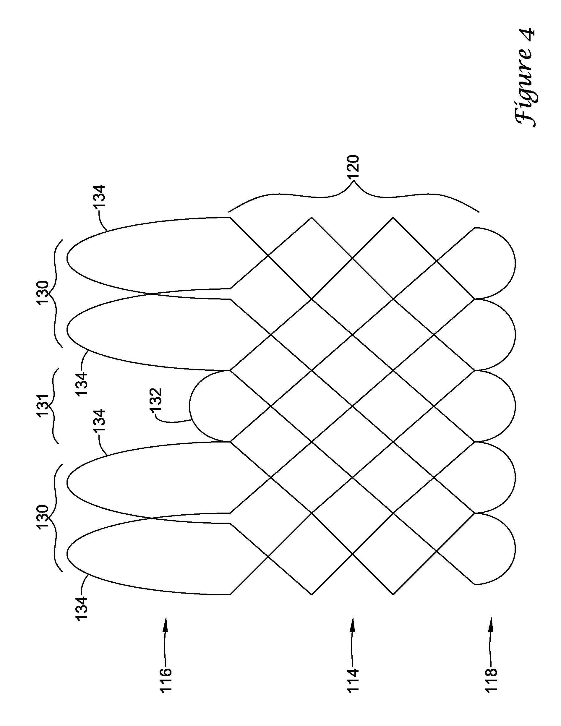
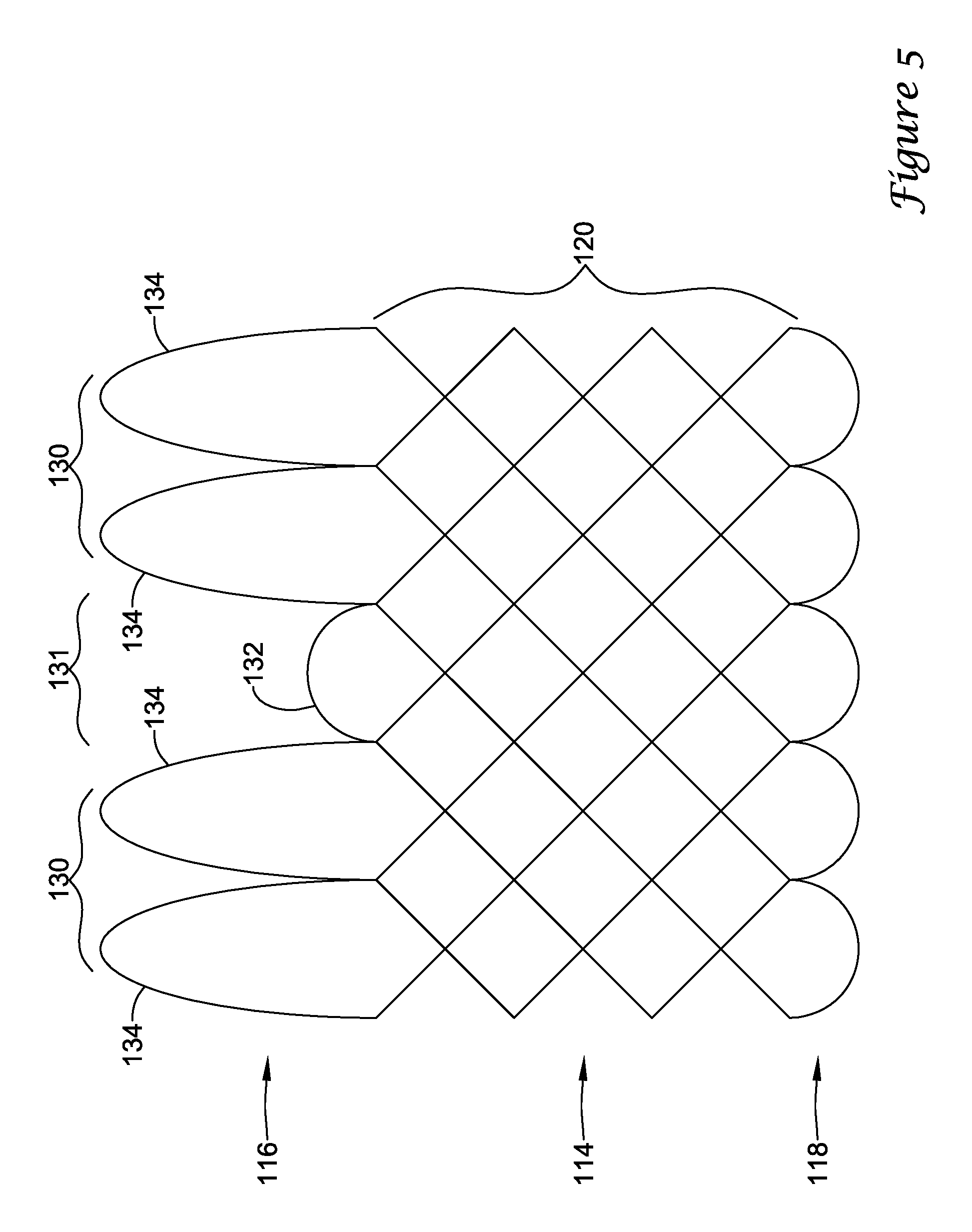
In a first aspect, an anchoring assistance device may comprise an expandable scaffold including a mid-body section defining a central longitudinal axis, the expandable scaffold having a cusp interface section extending axially from a distal end of the mid-body section, and a crown end arrangement extending axially from a proximal end of the mid-body section. The expandable scaffold may be configured to expand radially outward from a delivery configuration to a deployed configuration. The cusp interface section may include a plurality of loop portions arranged at radial intervals about the central longitudinal axis of the expandable scaffold, each loop portion being configured to be positioned adjacent a leaflet of an aortic valve. Each loop portion may be circumferentially spaced apart from another loop portion by a region having a deployment ring, the region being configured to span a commissure of the aortic valve and extending distally a shorter distance from the distal end than the loop portions.
In addition or alternatively, and in a second aspect, each loop portion includes two cusp loops.
In addition or alternatively, and in a third aspect, each region includes a minor loop, each minor loop having the deployment ring coupled thereto.
In addition or alternatively, and in a fourth aspect, the two cusp loops circumferentially overlap distal of the minor loops in the deployed configuration.
In addition or alternatively, and in a fifth aspect, the two cusp loops are circumferentially spaced apart from each other distal of the minor loops in the deployed configuration.
In addition or alternatively, and in a sixth aspect, each deployment ring is formed from a coiled loop portion of its minor loop.
In addition or alternatively, and in a seventh aspect, each deployment ring is integrally formed with its minor loop.
In addition or alternatively, and in an eighth aspect, each loop portion extends a longer circumferential distance around the central longitudinal axis than each region.
In addition or alternatively, and in a ninth aspect, the anchoring assistance device includes an equal number of loops portions and regions.
In addition or alternatively, and in a tenth aspect, an anchoring assistance device delivery system may comprise a delivery sheath having at least one lumen extending longitudinally therethrough and an actuator mechanism disposed at a proximal end of the delivery sheath. The anchoring assistance device delivery system may also comprise an elongate deployment member extending from the actuator mechanism to an anchoring assistance device disposable within a distal portion of the delivery sheath. The anchoring assistance device may comprise an expandable scaffold including a mid-body section defining a central longitudinal axis, the expandable scaffold having a cusp interface section extending axially from a distal end of the mid-body section, and a crown end arrangement extending axially from a proximal end of the mid-body section. The expandable scaffold may be configured to expand radially outward from a delivery configuration to a deployed configuration. The cusp interface section may include a plurality of loop portions arranged at radial intervals about the central longitudinal axis of the expandable scaffold, each loop portion being configured to be positioned adjacent a leaflet of an aortic valve. Each loop portion may be circumferentially spaced apart from another loop portion by a region having a deployment ring, the region being configured to span a commissure of the aortic valve and extending distally a shorter distance from the distal end than the loop portions. The elongate deployment member may be configured to releasably engage with the deployment rings such that the elongate deployment member actuates the expandable scaffold from the delivery configuration to the deployed configuration in response to activation of the actuator mechanism.
In addition or alternatively, and in an eleventh aspect, the actuator mechanism is configured to axially translate the elongate deployment member with respect to the delivery sheath.
In addition or alternatively, and in a twelfth aspect, the elongate deployment member includes a plurality of deployment loops at a distal end thereof, each deployment loop being configured to releasably engage with one deployment ring.
In addition or alternatively, and in a thirteenth aspect, each deployment loop extends at least partially through one deployment ring.
In addition or alternatively, and in a fourteenth aspect, proximal withdrawal of the elongate deployment member creates an interference between each deployment loop and its corresponding deployment ring such that the expandable scaffold is actuated from the delivery configuration to the deployed configuration.
In addition or alternatively, and in a fifteenth aspect, after achieving the deployed configuration, further proximal withdrawal of the elongate deployment member pulls each deployment loop through its corresponding deployment ring to disengage the elongate deployment member from the expandable scaffold.
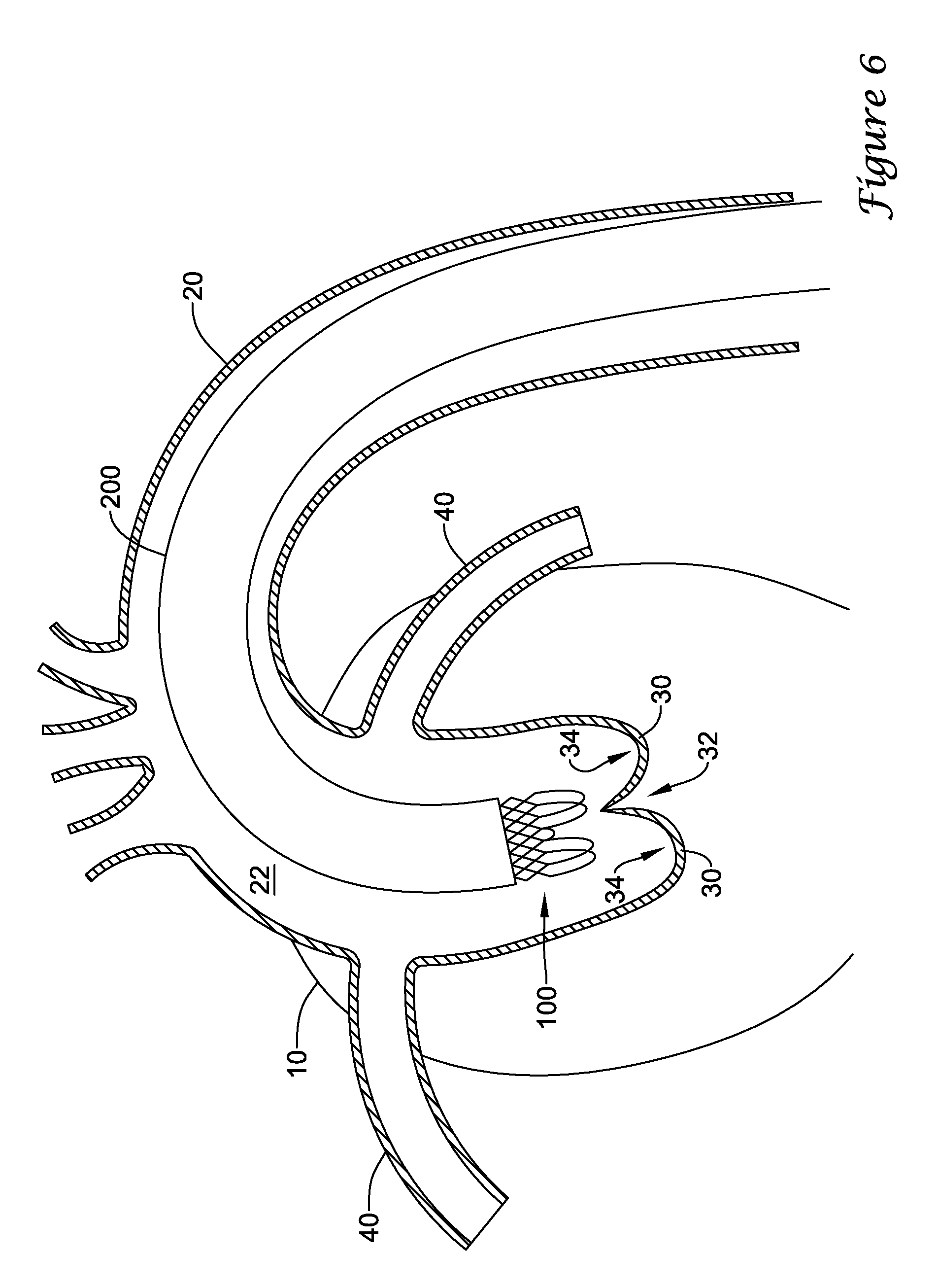
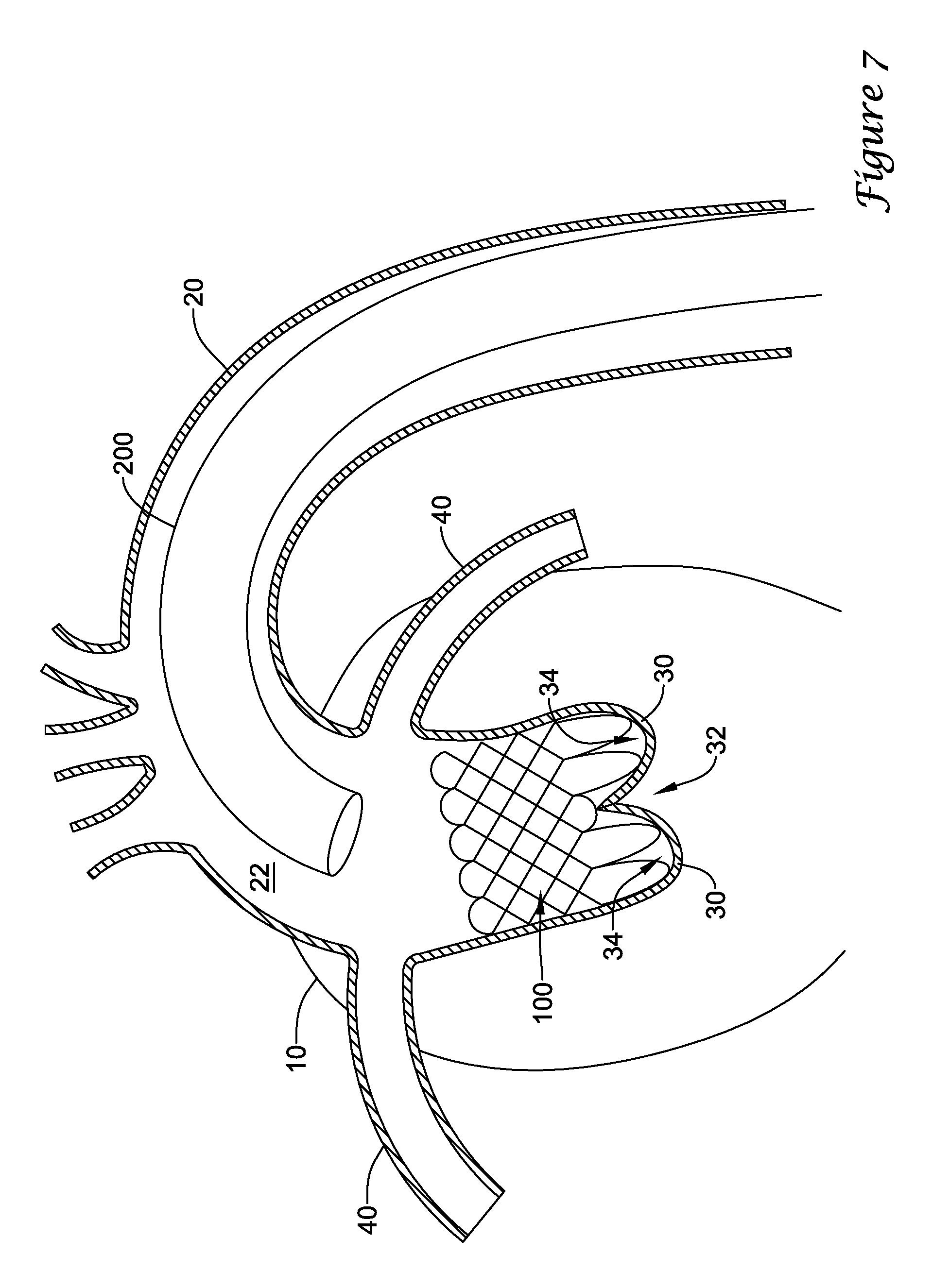
In addition or alternatively, and in a sixteenth aspect, a medical implant system may comprise a delivery sheath having at least one lumen extending longitudinally therethrough and an actuator mechanism disposed at a proximal end of the delivery sheath. The medical implant system may also comprise an anchoring assistance device comprising an expandable scaffold including a mid-body section defining a central longitudinal axis, the expandable scaffold having a cusp interface section extending axially from a distal end of the mid-body section, and a crown end arrangement extending axially from a proximal end of the mid-body section. The medical implant system may also comprise a replacement heart valve implant. The expandable scaffold may be configured to expand radially outward from a delivery configuration to a deployed configuration. The cusp interface section may include a plurality of loop portions arranged at radial intervals about the central longitudinal axis of the expandable scaffold, each loop portion being configured to be positioned adjacent a leaflet of an aortic valve. Each loop portion may be circumferentially spaced apart from another loop portion by a region having a deployment ring, the region being configured to span a commissure of the aortic valve and extending distally a shorter distance from the distal end than the loop portions. An elongate deployment member may extend from the actuator mechanism to the anchoring assistance device, the anchoring assistance device being disposable within a distal portion of the delivery sheath. The elongate deployment member may be configured to releasably engage with the deployment rings to actuate the expandable scaffold from the delivery configuration to the deployed configuration. The replacement heart valve implant may be configured to be at least partially disposed within the expandable scaffold in the deployed configuration.
In addition or alternatively, and in a seventeenth aspect, the replacement heart valve implant includes a transcatheter aortic valve implantation (TAVI) device or a transcatheter aortic valve replacement (TAVR) device.
In addition or alternatively, and in an eighteenth aspect, the replacement heart valve implant includes an anchor member expandable from a collapsed configuration to an installed configuration, the anchor member being configured to radially engage the expandable scaffold in the installed configuration.
In addition or alternatively, and in a nineteenth aspect, the anchoring assistance device prevents migration of the replacement heart valve implant when the anchor member is radially engaged with the expandable scaffold.
In addition or alternatively, and in a twentieth aspect, the elongate deployment member includes a plurality of deployment loops at a distal end thereof, each deployment loop being configured to releasably engage with one deployment ring. Proximal withdrawal of the elongate deployment member may create an interference between each deployment loop and its corresponding deployment ring such that the expandable scaffold is actuated from the delivery configuration to the deployed configuration.
The above summary of some embodiments, aspects, and/or examples is not intended to describe each disclosed embodiment or every implementation of the present disclosure. The Figures, and Detailed Description, which follow, more particularly exemplify these embodiments.
BRIEF DESCRIPTION OF THE DRAWINGS
The aspects of the disclosure may be more completely understood in consideration of the following detailed description of various embodiments in connection with the accompanying drawings, in which:
FIG. 1 is a schematic view of a portion of a heart and certain connected vasculature;
FIG. 2 is a flat pattern view of an example anchoring assistance device;
FIG. 3 is a partial side view of an example anchoring assistance device in a delivery configuration;
FIG. 4 is a partial side view of an example anchoring assistance device in a partially deployed configuration;
FIG. 5 is a partial side view of an example anchoring assistance device in a deployed configuration;
FIGS. 6-7 illustrate aspects of delivering an example anchoring assistance device into a body lumen;
FIGS. 8-9 illustrate aspects of delivering an example medical implant into an example anchoring assistance device within a body lumen;
FIGS. 9A-9B are partial cross-sectional views of an example medical implant disposed within an example anchoring assistance device;
FIG. 10 is a flat pattern view of an example anchoring assistance device;
FIG. 11 is a partial side view of an example anchoring assistance device in a delivery configuration;
FIG. 12 is a partial side view of an example anchoring assistance device in a partially deployed configuration;
FIG. 13 is a partial side view of an example anchoring assistance device in a deployed configuration;
FIG. 14 is a schematic view of an example deployment mechanism for use with an anchoring assistance device of the current disclosure;
FIGS. 15-19 illustrate aspects of delivering an example anchoring assistance device into a body lumen; and
FIGS. 20-21 illustrate aspects of delivering an example medical implant into an example anchoring assistance device within a body lumen.
While the aspects of the disclosure are amenable to various modifications and alternative forms, specifics thereof have been shown by way of example in the drawings and will be described in detail. It should be understood, however, that the intention is not to limit aspects of the disclosure to the particular embodiments described. On the contrary, the intention is to cover all modifications, equivalents, and alternatives falling within the spirit and scope of the disclosure.
DETAILED DESCRIPTION
The following description should be read with reference to the drawings, which are not necessarily to scale, wherein like reference numerals indicate like elements throughout the several views. The detailed description and drawings are intended to illustrate but not limit the claimed invention. Those skilled in the art will recognize that the various elements described and/or shown may be arranged in various combinations and configurations without departing from the scope of the disclosure. The detailed description and drawings illustrate example embodiments of the claimed invention.
For the following defined terms, these definitions shall be applied, unless a different definition is given in the claims or elsewhere in this specification.
All numeric values are herein assumed to be modified by the term "about," whether or not explicitly indicated. The term "about", in the context of numeric values, generally refers to a range of numbers that one of skill in the art would consider equivalent to the recited value (i.e., having the same function or result). In many instances, the term "about" may include numbers that are rounded to the nearest significant figure. Other uses of the term "about" (i.e., in a context other than numeric values) may be assumed to have their ordinary and customary definition(s), as understood from and consistent with the context of the specification, unless otherwise specified.
The recitation of numerical ranges by endpoints includes all numbers within that range, including the endpoints (e.g. 1 to 5 includes 1, 1.5, 2, 2.75, 3, 3.80, 4, and 5).
Although some suitable dimensions, ranges and/or values pertaining to various components, features and/or specifications are disclosed, one of skill in the art, incited by the present disclosure, would understand desired dimensions, ranges and/or values may deviate from those expressly disclosed.
As used in this specification and the appended claims, the singular forms "a", "an", and "the" include plural referents unless the content clearly dictates otherwise. As used in this specification and the appended claims, the term "or" is generally employed in its sense including "and/or" unless the content clearly dictates otherwise.
Relative terms such as "proximal", "distal", "advance", "retract", variants thereof, and the like, may be generally be considered with respect to the positioning, direction, and/or operation of various elements relative to a user/operator/manipulator of the device, wherein "proximal" and "retract" indicate or refer to closer to or toward the user and "distal" and "advance" indicate or refer to farther from or away from the user. Other relative terms, such as "upstream" and "downstream" refer to a direction of fluid flow within a lumen, such as a body lumen or blood vessel.
It is noted that references in the specification to "an embodiment", "some embodiments", "other embodiments", etc., indicate that the embodiment(s) described may include a particular feature, structure, or characteristic, but every embodiment may not necessarily include the particular feature, structure, or characteristic. Moreover, such phrases are not necessarily referring to the same embodiment. Further, when a particular feature, structure, or characteristic is described in connection with an embodiment, it would be within the knowledge of one skilled in the art to effect such feature, structure, or characteristic in connection with other embodiments, whether or not explicitly described, unless clearly stated to the contrary. That is, the various individual elements described below, even if not explicitly shown in a particular combination, are nevertheless contemplated as being combinable or arrangable with each other to form other additional embodiments or to complement and/or enrich the described embodiment(s), as would be understood by one of ordinary skill in the art.
For the purpose of clarity, certain identifying numerical nomenclature (e.g., first, second, third, fourth, etc.) may be used throughout the description and/or claims to name and/or differentiate between various described and/or claimed features. It is to be understood that the numerical nomenclature is not intended to be limiting and is exemplary only. In some embodiments, alterations of and deviations from previously-used numerical nomenclature may be made in the interest of brevity and clarity. That is, a feature identified as a "first" element may later be referred to as a "second" element, a "third" element, etc. or may be omitted entirely, and/or a different feature may be referred to as the "first" element. The meaning and/or designation in each instance will be apparent to the skilled practitioner.
The terms "transaortic valve implantation" and "transcatheter aortic valve implantation" may be used interchangeably, and may each be referred to using the acronym "TAVI".
The terms "transaortic valve replacement" and "transcatheter aortic valve replacement" may be used interchangeably, and may each be referred to using the acronym "TAVR".
FIG. 1 illustrates a schematic view of a portion of a patient's heart 10 and certain connected vasculature, such as the aorta 20 connected to the heart 10 by the aortic arch 22, and the coronary arteries 40. Leaflets 30 of an aortic valve may be seen schematically where the aorta 20 meets and/or joins the heart 10. On a downstream side of the leaflets 30 is an area described herein as a cusp 34, where the cusp 34 is a space between the leaflets 30 and a wall of the aorta 20 and/or the aortic arch 22 immediately downstream of and/or adjacent to the aortic valve. The leaflets 30 meet or intersect at a commissure 32. As such, is a tricuspid heart valve, such as a normal aortic valve, three commissures 32 will be present with three cusps 34 disposed therebetween. In a bicuspid heart valve, two commissures 32 will be present with two cusps 34 disposed therebetween.
An exemplary implantable anchoring assistance device 100, shown in a flat pattern view in FIGS. 2 and 10 for example, may be configured to be positioned in a body lumen for a variety of medical applications. For example, the anchoring assistance device 100 may be used to treat a stenosis in a blood vessel, used to maintain a fluid opening or pathway in the vascular, urinary, biliary, tracheobronchial, esophageal, or renal tracts, or position a device such as an artificial or replacement valve or filter within a body lumen, in some instances. In some instances, the anchoring assistance device 100 may be a prosthetic graft, a stent-graft, or a stent (e.g., a vascular stent, tracheal stent, bronchial stent, esophageal stent, etc.). Although illustrated herein as a stent or stent-like structure, the anchoring assistance device 100 may be any of a number of devices that may be introduced endoscopically, subcutaneously, percutaneously, and/or surgically to be positioned within an organ, tissue, or body lumen, such as a heart, artery, vein, urethra, esophagus, trachea, bronchus, bile duct, or the like.
In some embodiments, the anchoring assistance device 100 may be a self-expanding anchoring assistance device configured to automatically expand from a delivery configuration to a deployed configuration upon the removal of a constraining force acting on the anchoring assistance device. In other embodiments, the anchoring assistance device 100 may be a mechanically expandable anchoring assistance device configured to be expanded from a delivery configuration to a deployed configuration through the application of a mechanical force acting on the anchoring assistance device (e.g., a radially expanding balloon or actuation of a deployment member). In some embodiments, an anchoring assistance device combining any, some, or all elements of a self-expanding anchoring assistance device and a mechanically expandable anchoring assistance device may be utilized.
In some embodiments, the anchoring assistance device 100 may be a generally tubular member formed from an expandable scaffold 112 having a mid-body section 114 defining a central longitudinal axis. In some embodiments, the expandable scaffold 112 may include a cusp interface section 116 extending axially or longitudinally in a distal direction from a distal end of the mid-body section 114. In some embodiments, the expandable scaffold 112 may include a crown end arrangement 118 extending axially or longitudinally in a proximal direction from a proximal end of the mid-body section 114.
In some embodiments, the expandable scaffold 112 may include an outer surface defining an outer diameter, and an inner surface defining an inner diameter and/or a lumen extending through the expandable scaffold 112 along the central longitudinal axis. In some embodiments, the mid-body section 114 of the expandable scaffold 112 may include a plurality of strut rows 120 arranged along the length of the anchoring assistance device 100. In some instances, the plurality of strut rows 120 may extend circumferentially around a perimeter of the expandable scaffold 112.
As used herein, the outer surface of the expandable scaffold 112 is intended to refer to a radially outward facing surface of the plurality of strut rows 120 commensurate with the outer diameter of the expandable scaffold 112 and/or the anchoring assistance device 100. As used herein, the inner surface of the expandable scaffold 112 is intended to refer to a radially inward facing surface of the plurality of strut rows 120 commensurate with the inner diameter and/or the lumen of the expandable scaffold 112 and/or the anchoring assistance device 100.
In some embodiments, the plurality of strut rows 120 may include two, three, four, five, six, or more strut rows arranged along the length of the expandable scaffold 112. In some embodiments, adjacent strut rows may define a gap or interstice therebetween, each gap or interstice having a length along the central longitudinal axis and spacing the adjacent strut rows 120 apart by the gap or interstice. Thus, the length of the anchoring assistance device 100 may be dictated, at least in part, by the number of strut rows 120 and/or the length(s) of the gaps or interstices. In some embodiments, some or all of the plurality of strut rows 120 may be immediately adjacent each other with no gap or interstice therebetween, and thus in some embodiments, may be connected directly together. In at least some embodiments, the expandable scaffold 112 and/or the mid-body section 114 may be formed as a cross-patterned braid or similar structure formed from a plurality of individual filaments.
In some embodiments, each strut row 120 may include continuously undulating struts defining interstitial spaces or openings therebetween. In some embodiments, each strut row 120 may include a plurality of intersecting struts or filaments. The struts of each strut row 120 may include alternating peaks 124 and valleys 126, the peaks 124 and valleys 126 corresponding to where individual segments of the struts intersect, converge, and/or diverge. The peaks 124 associated with a strut row 120 are located toward a first end of the expandable scaffold 112 while the valleys 126 associated with a strut row 120 are located toward a second opposite end of the expandable scaffold 112. In some embodiments, the peaks 124 of one strut row 120 may be connected directly to the valleys 126 of an adjacent strut row 120, and vice versa.
The anchoring assistance device 100 may be formed of any desired material, such as a biocompatible material including biostable, bioabsorbable, biodegradable, and/or bioerodible materials. For instance, the anchoring assistance device 100 may be formed of a metallic material, a polymeric material, or suitable combinations thereof. Some suitable metallic materials include, but are not necessarily limited to, stainless steel, tantalum, tungsten, nickel-titanium alloys such as those possessing shape memory properties commonly referred to as nitinol, nickel-chromium alloys, nickel-chromium-iron alloys, cobalt-chromium-nickel alloys, or other suitable metals, or combinations or alloys thereof. Some suitable polymeric materials include, but are not necessarily limited to, polyamide, polyether block amide, polyethylene, polyethylene terephthalate, polypropylene, polyvinylchloride, polyurethane, polytetrafluoroethylene, polysulfone, and copolymers, blends, mixtures or combinations thereof.
In some instances, the expandable scaffold 112 of the anchoring assistance device 100 may be formed as a monolithic structure from a single tubular member, such as a metallic tube. For example, the expandable scaffold 112 may be cut (e.g., laser cut) from a single metallic tubular member and then expanded. Thus, the plurality of strut rows 120 of the expandable scaffold 112 may be formed as a monolithic structure cut from a single metallic tube, in some instances. In some instances, the plurality of strut rows 120 of the expandable scaffold 112 may be cut from a single polymeric tubular member. In some embodiments, the expandable scaffold 112 may be machined, chemically etched, or otherwise formed as a monolithic structure from a single tubular member.
In some embodiments, the mid-body section 114 of the expandable scaffold 112 may be formed as a cross-patterned braid. In some embodiments, the cusp interface section 116 and the crown end arrangement 118 may be bonded, attached, joined, or otherwise connected to the mid-body section 114. In some embodiments, the cusp interface section 116 and the crown end arrangement 118 may be integrally and/or monolithically formed with the mid-body section 114. In some embodiments, the mid-body section 114, the cusp interface section 116, and/or the crown end arrangement 118 may be formed from different materials. In some embodiments, the mid-body section 114, the cusp interface section 116, and/or the crown end arrangement 118 may be formed from similar materials or the same material. In some embodiments, the expandable scaffold 112 may be formed, manufactured, or otherwise made by applying and/or positioning a plurality of individual filaments on or around a mandrel or other tool. In some embodiments, the cusp interface section 116 and/or the crown end arrangement 118 may be formed from the same plurality of filaments used to form the mid-body section 114.
In some embodiments, the crown end arrangement 118 may form a series of individual loops connecting adjacent filaments of the mid-body section 114, as seen in FIGS. 2 and 10, for example. In some embodiments, the series of individual loops of the crown end arrangement 118 may not overlap or intersect each other distal of the mid-body section 114. In some embodiments, the series of individual loops of the crown end arrangement 118 may overlap or intersect each other distal of the mid-body section 114. In some embodiments, the series of individual loops of the crown end arrangement 118 may extend proximally from the mid-body section 114 a shorter or smaller distance than the cusp interface section 116 extends distally from the mid-body section 114.
In some embodiments, the cusp interface section 116 may include a plurality of loop portions 130 arranged at radial intervals about the central longitudinal axis of the expandable scaffold 112. In some embodiments, the plurality of loop portions 130 of the cusp interface section 116 may include three loop portions 130 arranged at radial intervals about the central longitudinal axis of the expandable scaffold 112. In some embodiments, the plurality of loop portions 130 of the cusp interface section 116 may include two loop portions, three loops portions, four loop portion, five loop portions, six loop portions, or other suitable numbers or quantities of loop portions as desired. In some embodiments, the plurality of loop portions 130 may be arranged at substantially equal radial intervals about the central longitudinal axis of the expandable scaffold 112 (e.g., 180 degrees, 120 degrees, 90 degrees, 72 degrees, 60 degrees, etc.).
In some embodiments, each of the plurality of loop portions 130 (e.g., each of the three loop portions) may be circumferentially spaced apart from another loop portion 130 by a region 131 extending distally from the distal end of the mid-body section 114 a shorter distance from the distal end than the plurality of loop portions 130. In some embodiments, a region 131 may include a minor loop 132. In some embodiments, a region 131 has a deployment ring 133 and/or a minor loop 132 may include a deployment ring 133 coupled thereto. In some embodiments, each deployment ring 133 may be formed from a coiled loop portion of its minor loop 132. In some embodiments, each deployment ring 133 may be integrally formed with its minor loop 132.
In some embodiments, the anchoring assistance device 100 may include an equal number or quantity of loop portions 130 and regions 131 and/or minor loops 132. For example, in some embodiments, the expandable scaffold may include three loop portions 130 and three regions 131 and/or minor loops 132, each region 131 and/or minor loop 132 being disposed between two adjacent loop portions 130. In some embodiments, each loop portion 130 may extend a longer or greater circumferential distance around the central longitudinal axis than each region 131 and/or minor loop 132.
In some embodiments, each loop portion 130 may include two or more cusp loops 134. In some embodiments, each loop portion 130 may include two cusp loops 134. In some embodiments, each loop portion 130 may include three cusp loops, four cusp loops, five cusp loops, or other suitable numbers or quantities of cusp loops as desired. In some embodiments, at least a portion of each of the two or more cusp loops 134 (e.g., the two cusp loops 134) may circumferentially overlap distal of the region(s) 131 and/or the minor loop(s) 132 in the deployed configuration, as seen in FIGS. 4 and 12 for example, which in some embodiments may be considered to illustrate a partially deployed configuration. In some embodiments, the two or more cusp loops 134 (e.g., the two cusp loops 134) may be circumferentially spaced apart from each other distal of the region(s) 131 and/or the minor loop(s) 132 in the deployed configuration, as seen in FIGS. 5 and 13 for example. In other words, in some embodiments, any portion of the two or more cusp loops 134 disposed distal of the region(s) 131 and/or the minor loop(s) 132 may not circumferentially overlap each other. Different configurations (e.g., partial to complete or total deployment) of the plurality of loop portions 130 may permit a single size of anchoring assistance device 100 to be used in a number of different size body lumens.
In use, an anchoring assistance device 100 may be advanced to a target site (e.g., a heart valve, an aortic valve, etc.) within a body lumen, such as a body lumen of the vascular, urinary, biliary, tracheobronchial, esophageal, or renal tracts. In some embodiments, the anchoring assistance device 100 may be advanced percutaneously through a patient's vasculature within a delivery sheath 200 in the delivery configuration (as seen in FIGS. 3 and 11 without the delivery sheath 200) through a patient's aorta 20, through the aortic arch 22, and into the cusps 34 and/or adjacent to the leaflets 30 of an aortic valve, which may be defective. As may be seen in FIGS. 6-7 and 15-19, after advancing the anchoring assistance device 100 and/or the delivery sheath 200 to the target site (e.g., within or adjacent to the aortic valve), the delivery sheath 200 may be retracted proximally relative to the anchoring assistance device 100 (and/or the anchoring assistance device 100 may be advanced distally relative to the delivery sheath 200) to deploy the anchoring assistance device 100 from the delivery configuration to the deployed configuration (such as described above) at the target site. Similarly, as seen in FIGS. 15-19, after releasing the anchoring assistance device 100 from the delivery sheath 200, an elongate deployment member 250 extending from an actuator mechanism 252 to the anchoring assistance device 100 may be actuated to axially translate the elongate deployment member 250 with respect to the delivery sheath 200 to actuate the anchoring assistance device 100 from the delivery configuration to the deployed configuration, as will be explained in more detail below.
In some embodiments, each loop portion 130 of the expandable scaffold 112 may be configured to be positioned immediately adjacent to and/or downstream of a heart valve (e.g., an aortic valve) in the deployed configuration (e.g., into the cusps 34 between the leaflets 30 and the wall of the aorta 20 and/or the aortic arch 22). In some embodiments, each region 131 and/or minor loop 132 may be configured to span and/or be positioned downstream and over a commissure 32 of the heart valve (e.g., aortic valve) in the deployed configuration. In at least some embodiments, the anchoring assistance device 100 may be disposed between the native aortic valve cusps 34 and/or leaflets 30 and the openings or ostia of the coronary arteries 40. In general, the anchoring assistance device 100 may be sized to avoid covering or overlapping an ostium of the coronary arteries 40.
In some embodiments, it may be beneficial to deploy a medical implant (e.g., a replacement heart valve implant) within the anchoring assistance device 100, as illustrated in FIGS. 8-9 and 20-21 for example. In some embodiments, a replacement heart valve implant 300 may be disposed within the delivery sheath 200 proximal of the anchoring assistance device 100. Further retraction of the delivery sheath 200 relative to the replacement heart valve implant 300 may deploy the replacement heart valve implant 300 from the delivery sheath 200. In some embodiments, after deployment of the anchoring assistance device 100, the delivery sheath 200 may be withdrawn from the target site and/or the patient's vasculature and a deployment sheath 400 as described herein may be advanced to the target site in its place. In some embodiments, a deployment sheath 400 may be extended and/or advanced through the delivery sheath 200, the deployment sheath 400 carrying a replacement heart valve implant 300 therein, as seen in FIGS. 8 and 20. In some embodiments, the replacement heart valve implant 300 may include or take the form of a transaortic valve implantation or transcatheter aortic valve implantation (TAVI) device or a transaortic valve replacement or transcatheter aortic valve replacement (TAVR) device. Following advancement of the deployment sheath 400 to the target site, the replacement heart valve implant 300 may then be deployed and/or disposed at least partially within the anchoring assistance device 100. In some embodiments, when the replacement heart valve implant 300 is expanded within the anchoring assistance device 100, the native heart valve leaflets 30 may be squeezed, pinched, trapped, or otherwise disposed between the anchoring assistance device 100 and the replacement heart valve implant 300, as seen in FIGS. 9, 9A, 9B, and 21.
A medical implant system may include an anchoring assistance device 100, such as that described above, and a replacement heart valve implant 300 at least partially disposed within the anchoring assistance device 100 in the deployed configuration. In at least some embodiments, the replacement heart valve implant 300 may include an anchor member 220 reversibly actuatable from a collapsed configuration to an installed configuration. In some embodiments, the anchor member 220 may be delivered though a deployment sheath 400 in the collapsed configuration, as seen in FIGS. 8 and 20. After deploying the replacement heart valve implant 300 from the deployment sheath 400, the anchor member 220 may be reversibly axially shortened and/or radially expanded from the collapsed configuration to the installed configuration. In at least some embodiments, the anchor member 220 may be configured to radially engage the expandable scaffold 112 when the anchor member 220 is in the installed configuration and the expandable scaffold 112 is in the deployed configuration, as seen in FIGS. 9 and 21. In some embodiments, the anchoring assistance device 100 may prevent migration of the replacement heart valve implant 300 when the anchor member 220 is radially engaged with the expandable scaffold 112.
FIG. 2 illustrates a flat pattern view of the expandable scaffold 112 of the anchoring assistance device 100. It is noted that the pattern shown in FIG. 2 is illustrated as if the expandable scaffold 112 were cut longitudinally and flattened, but one of skill in the art would understand that the pattern would extend circumferentially about the central longitudinal axis. As shown in FIG. 3, in the delivery configuration, the peaks 124 and valleys 126 of the plurality of strut rows 120 may be closely arranged.
Similarly, FIG. 10 illustrates a flat pattern view of the expandable scaffold 112 of the anchoring assistance device 100. It is noted that the pattern shown in FIG. 10 is illustrated as if the expandable scaffold 112 were cut longitudinally and flattened, but one of skill in the art would understand that the pattern would extend circumferentially about the central longitudinal axis. As shown in FIG. 11, in the delivery configuration, the peaks 124 and valleys 126 of the plurality of strut rows 120 may be closely arranged.
The anchoring assistance device 100 may be configured to engage a wall of a body lumen in the deployed configuration to inhibit migration of the anchoring assistance device 100 subsequent to implanting the anchoring assistance device 100 in the body lumen. For example, the anchoring assistance device 100 may engage the tissue between cartilage rings within the tracheal anatomy to provide anti-migration support for the anchoring assistance device 100. In at least some embodiments, the anchoring assistance device 100 may include one or more anchoring protrusions, hooks, barbs, or other similar features configured to engage and/or at least partially penetrate a wall of the body lumen.
In the deployed configuration, a space or opening may be defined between each of the struts of the plurality of strut rows 120. In some instances, the space or opening may be unobstructed by any other structure of the anchoring assistance device 100. In some instances, the space or opening may be configured to accept tissue ingrowth and/or the struts of the plurality of strut rows 120 may be configured to engage tissue or be encapsulated by tissue ingrowth. Accordingly, tissue ingrowth through the space or opening and covering or encapsulating the struts of the plurality of strut rows 120 subsequent to implanting the anchoring assistance device 100 may further secure the anchoring assistance device 100 in place within the patient's anatomy and thereby prevent migration of the anchoring assistance device 100.
As described above, each gap or interstice between adjacent strut rows 120 may have a length along the central longitudinal axis of the expandable scaffold 112 and may space the adjacent strut rows 120 apart. In some embodiments, the gaps or interstices between adjacent strut rows 120 may be defined by the valley(s) 126 of one strut row 120 and the peak(s) 124 of another strut row 120 immediately adjacent to the valley(s) 126. In some embodiments, the lengths of the gaps or interstices between adjacent strut rows 120 may vary along the length of the expandable scaffold 112.
As an example, in some embodiments, a first strut row 120 and a second strut row 120 may define a first gap or interstice therebetween, the second strut row 120 and a third strut row 120 may define a second gap or interstice therebetween, and the third strut row 120 and a fourth strut row 120 may define a third gap or interstice therebetween, wherein a length of the first interstice may be different from a length of the second interstice and/or a length of the third interstice may be different from the length of the second interstice. In one instance, a first interstice, a second interstice, and a third interstice may each be different lengths. In another instance, a first interstice may be shorter than a second interstice, which may be shorter than a third interstice. In yet another instance, a first interstice and a third interstice may be a same length that is a different length (e.g., shorter or longer) than a second interstice.
In some embodiments, an anchoring assistance device 100 may include a polymeric cover covering the struts of plurality of strut rows 120. In some embodiments, openings or spaces between the struts of the plurality of strut rows 120 are devoid of the polymeric cover and open to permit tissue ingrowth therethrough. The polymeric cover may be any desired polymeric coating, such as a polyurethane coating or silicone coating, for example. Other coatings and/or coating materials are also contemplated. In some instances, the polymeric cover may include a therapeutic agent embedded therein, disposed thereon, etc., if desired.
In some embodiments, the spaces or openings permit tissue ingrowth, while the polymeric cover prevents tissue ingrowth around and/or through other portions of the anchoring assistance device 100. Accordingly, subsequent to implantation of the anchoring assistance device 100, tissue may grow through the spaces or openings and thereby prevent migration of the implanted anchoring assistance device 100. However, in the event that it is desired to remove or reposition the anchoring assistance device 100 at a subsequent time after tissue ingrowth has occurred, the ingrown tissue can be cut away from the struts of the plurality of strut rows 120 and/or the struts of the plurality of strut rows 120 can be otherwise released from the ingrown tissue. Since the ingrown tissue is only located at discrete locations (e.g., at the spaces or openings), the procedure for removing the anchoring assistance device 100 may be less traumatic than if the tissue were ingrown throughout the entire expandable scaffold 112, such as with a bare or completely uncovered anchoring assistance device.
If it is desired to coat the expandable scaffold 112 with a polymeric cover, the polymeric cover may be applied to the expandable scaffold 112. For example, the expandable scaffold 112 may be coated with a polymeric cover by dipping the expandable scaffold 112 into a reservoir of a polymeric material solution. In other instances, a polymeric material solution may be sprayed onto the expandable scaffold 112, or otherwise applied to the expandable scaffold 112.
In some embodiments, a layer of the polymeric material solution may be formed across the expandable scaffold 112, covering the plurality of strut rows 120 and spanning the gaps or interstices between adjacent strut rows 120, as well as the spaces or openings between the struts of the plurality of strut rows 120. In some embodiments, the expandable scaffold 112 may be subjected to a process for selectively removing the layer of polymeric material solution from the spaces or openings between the struts of the plurality of strut rows 120 while retaining the polymeric material solution covering the struts of the plurality of strut rows 120 and spanning the gaps or interstices between adjacent strut rows 120.
For example, a fluid (e.g., air) may be blown toward the spaces or openings to selectively remove the coating from the spaces or openings. In other examples, the polymeric coating material extending across the spaces or openings may be mechanically popped or ruptured, or the surface tension of the polymeric coating material extending across the spaces or openings may be modified, such as chemically modified, to pop or rupture the polymeric coating material extending across the spaces or openings. In other examples, the polymeric coating material may be prevented from spanning the spaces or openings between the struts of the plurality of strut rows 120 while retaining the coating covering the struts of the plurality of strut rows 120 and spanning the gaps or interstices between adjacent strut rows 120. For example, the spaces or openings may be masked off prior to applying the polymeric coating material and then subsequently removed, or the struts of the plurality of strut rows 120 may be pre-treated, such as coated with a material, preventing wetting of the polymeric coating material across the spaces or openings when applying the polymeric coating material.
In some instances, a single layer of the polymeric coating may be applied to form the polymeric cover. In other instances, multiple layers of the polymeric coating may be applied to form the polymeric cover. The coating extending across the spaces or openings may be ruptured after each layer of the coating is applied or after multiple layers of the coating have been applied. For example, fluid may be blown toward the spaces or openings to rupture the coating extending across the spaces or openings after each layer of the coating is applied, or after multiple layers of the coating have been applied.
The polymeric material solution coating the expandable scaffold 112 may then be cured to form the polymeric cover disposed on the expandable scaffold 112. In some instances, the polymeric cover may extend the entire length of the expandable scaffold 112. In other instances, the polymeric cover may extend along only a portion of the length of the expandable scaffold 112, if desired.
Some embodiments may utilize a mechanical deployment member 250, as seen in FIG. 14 for example. In some embodiments, an anchoring assistance device delivery system may include a delivery sheath 200 having at least one lumen extending longitudinally therethrough and an actuator mechanism 252 disposed at a proximal end of the delivery sheath 200. In some embodiments, an anchoring assistance device delivery system may include an elongate deployment member 250 extending from the actuator mechanism 252 to an anchoring assistance device 100 disposable within a distal portion of the delivery sheath 200, as seen in FIGS. 14-15 for example. In some embodiments, the elongate deployment member 250 may be configured to releasably engage with the deployment rings 133 of the anchoring assistance device 100 such that the elongate deployment member 250 actuates the expandable scaffold 112 from the delivery configuration (as seen in FIG. 16 for example) to the deployed configuration (as seen in FIGS. 17-19 for example) in response to activation of the actuator mechanism 252. In some embodiments, the actuator mechanism 252 may be configured to axially translate the elongate deployment member 250 with respect to the delivery sheath 200 and/or the anchoring assistance device 100.
In some embodiments, the elongate deployment member 250 may include an elongate shaft 256 extending distally from the actuator mechanism 252. In some embodiments, the elongate shaft 256 may be a solid member of fixed length, such as a rod, cylinder, pin, shaft, and the like. In some embodiments, the elongate shaft 256 may be a hollow member of fixed length such as a shaft with one or more lumens extending therethrough, a hypotube, a tubular member, and the like. In some embodiments, the elongate shaft 256 may be a hollow member of variable length with one or more lumens extending therethrough, such as in a telescoping and/or collapsible arrangement. In some embodiments, the elongate shaft 256 may be metallic or polymeric, and flexible or rigid (or semi-rigid), as desired.
In some embodiments, the actuator mechanism 252 may include a handle fixed to a proximal end of the elongate deployment member 250 and/or the elongate shaft 256. In some embodiments, the actuator mechanism 252 may be a proximal end of the elongate deployment member 250 and/or the elongate shaft 256. In some embodiments, the elongate deployment member 250 may include an engagement means 260 disposed at a distal end thereof, the engagement means 260 being configured to releasably engage with the anchoring assistance device 100 and/or the deployment rings 133. In some embodiments, the engagement means 260 may include an inflatable balloon (not shown). In some embodiments, the elongate deployment member 250 and/or the engagement means 260 may include a plurality of deployment loops 264 at a distal end thereof, each deployment loop 264 being configured to releasably engage with one deployment ring 133. In some embodiments, the plurality of deployment loops 264 may be connected to a distal end of the elongate shaft 256 by one or more wires 262 extending therebetween. In some embodiments, one wire 262 may extend from a distal end of the elongate shaft 256 to a proximal end of one deployment loop 264. In other words, each of the plurality of deployment loops 264 may be connected to a distal end of the elongate shaft 256 by a corresponding wire 262. In some embodiments, the one or more wires 262 may extend from the distal end of the elongate shaft 256 through one or more lumens of the elongate shaft 256 to the actuator mechanism 252. In some embodiments, the one or more wires 262 may join together into a single actuator wire extending through the elongate shaft 256 to the actuator mechanism 252. In some embodiments, the one or more wires 262 may be fixedly attached to the distal end of the elongate shaft 256--for example, individually, via the aforementioned single actuator wire, or some combination thereof.
In some embodiments, the actuator mechanism 252 may include an actuator element 254, such as a rotatable wheel, a slide, a lever, a knob, and the like. In at least some embodiments, actuation of the actuator element 254 may proximally retract the elongate shaft 256, the single actuator wire, and/or the one or more wires 262 relative to the actuator mechanism 252. In other words, actuation of the actuator element 254 may translate a distal end of the elongate shaft 256, the single actuator wire, and/or the one or more wires 262 closer to the actuator mechanism 252 (i.e., proximally). In some embodiments, the elongate deployment member 250 may be a substantially fixed element of constant length. In other words, individual elements of the elongate deployment member 250 may be fixed in position relative to each other. Proximal withdrawal of the actuator mechanism 252 may axially translate the elongate deployment member 250 in a proximal direction with respect to the delivery sheath 200 and/or the anchoring assistance device 100.
As may be seen in FIGS. 16-18, each deployment loop 264 may extend at least partially through one deployment ring 133. In some embodiments, each deployment loop 264 may extend completely or almost completely (i.e., greater than 75%, greater than 80%, greater than 90%, etc.) through one deployment ring 133, such as when the expandable scaffold 112 is in the delivery configuration. In some embodiments, proximal withdrawal of the elongate deployment member 250, such as by activation of the actuator mechanism 252, may create an interference between each deployment loop 264 and its corresponding deployment ring 133, such that the expandable scaffold 112 may be actuated from the delivery configuration to the deployed configuration. In at least some embodiments, after achieving the deployed configuration, further proximal withdrawal of the elongate deployment member 250 may pull each deployment loop 264 through its corresponding deployment ring 133 to disengage the elongate deployment member 250 and/or the plurality of deployment loops 264 from the expandable scaffold 112, as seen in FIG. 19 for example. In some embodiments, after achieving the deployed configuration, further proximal withdrawal of the elongate deployment member 250 may pull each deployment loop 264 completely through its corresponding deployment ring 133 to disengage the elongate deployment member 250 and/or the plurality of deployment loops 264 from the expandable scaffold 112.
In some embodiments, the deployment rings 133 may have a maximum inner extent and the plurality of deployment loops 264 may have a maximum outer extent greater than the maximum inner extent of the deployment rings 133 in an undeformed or natural condition. This arrangement may be easily seen in FIG. 16, for example. In some embodiments, the deployment rings 133 may be made or formed from the same material as the expandable scaffold 112, including similar physical characteristics (i.e., size, stiffness, etc.). In some embodiments, the deployment rings 133 may be made or formed from the same material as the expandable scaffold 112, with different physical characteristics (i.e., size, stiffness, etc.) In some embodiments, the deployment rings 133 may be made or formed from a different material having similar physical characteristics to the expandable scaffold 112, or the deployment rings 133 may be made or formed from a different material having different physical characteristics from the expandable scaffold 112.
As mentioned above, an interference is created when the plurality of deployment loops 264 is pulled against and/or through the deployment rings 133, the interference resulting in a pull force required to deform and/or disengage the plurality of deployment loops 264 from the deployment rings 133. A mismatch in the size of the features may create this interference, and in some cases may define the pull force required to deform and/or disengage the plurality of deployment loops 264 from the deployment rings 133. In some embodiments, size of the plurality of deployment loops 264 may affect the pull force required to deform and/or disengage the plurality of deployment loops 264 from the deployment rings 133, wherein larger deployment loops 264 may be easier to deform and pull through the deployment rings 133, thereby reducing the pull force required to deform and/or disengage the plurality of deployment loops 264 from the deployment rings 133. Similarly, larger deployment rings 133 may provide less resistance to deformation and pulling the deployment loops 264 therethrough, thereby reducing the pull force required to deform and/or disengage the plurality of deployment loops 264 from the deployment rings 133. In a similar way, stiffer materials may be less likely to bend, deflect, or deform when an interference is created, and thus the pull force required to deform and/or disengage the plurality of deployment loops 264 from the deployment rings 133 may be higher for such materials. In some embodiments, the plurality of deployment loops 264 may be made or formed from a thinner and/or more flexible material than the deployment rings 133 and/or the expandable scaffold 112, which may reduce the pull force required to deform and/or disengage the plurality of deployment loops 264 from the deployment rings 133.
In some embodiments, the plurality of deployment loops 264 may be formed in a figure-eight configuration. In these embodiments, each "lobe" of the figure-eight may have a maximum outer extent greater than the maximum inner extent of the deployment rings 133. As such, each "lobe" may function in the same or similar manner to the plurality of deployment loops 264 described above. Additionally, the figure-eight configuration may permit the plurality of deployment loops 264 to function as a mechanism of action to both deploy the expandable scaffold 112 (by proximal withdrawal as described above) and to collapse the expandable scaffold 112 back toward the delivery configuration through distal actuation of the elongate deployment member 250 and/or the plurality of deployment loops 264 relative to the expandable scaffold 112 and/or the deployment rings 133.
Those skilled in the art will recognize that aspects of the present disclosure may be manifested in a variety of forms other than the specific embodiments described and contemplated herein. Accordingly, departure in form and detail may be made without departing from the scope and spirit of the present disclosure as described in the appended claims. This may include, to the extent that it is appropriate, the use of any of the features of one example embodiment or aspect being used in other embodiments or aspects.
* * * * *
References
D00000
D00001
D00002
D00003
D00004
D00005
D00006
D00007
D00008
D00009
D00010
D00011
D00012
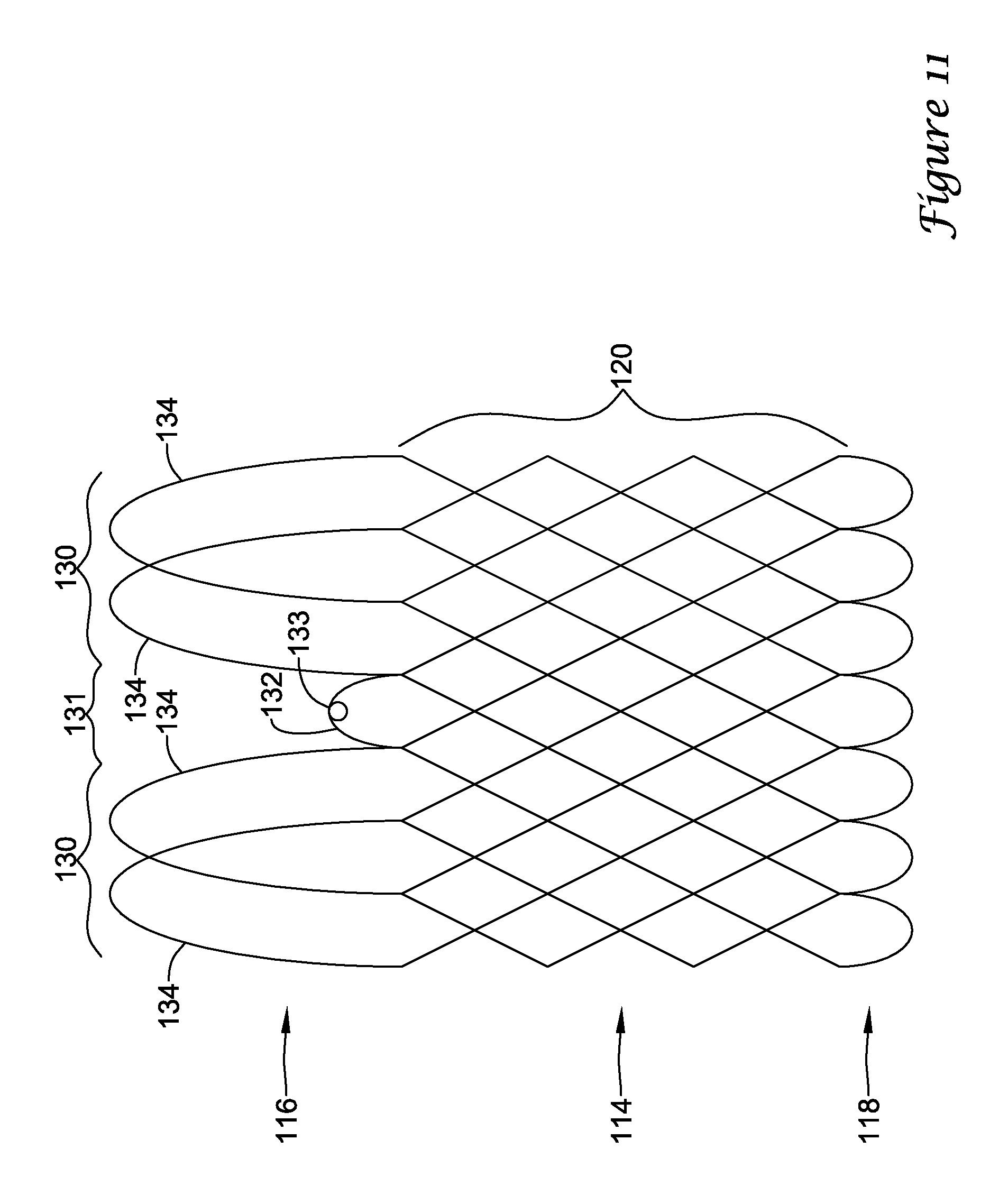
D00013
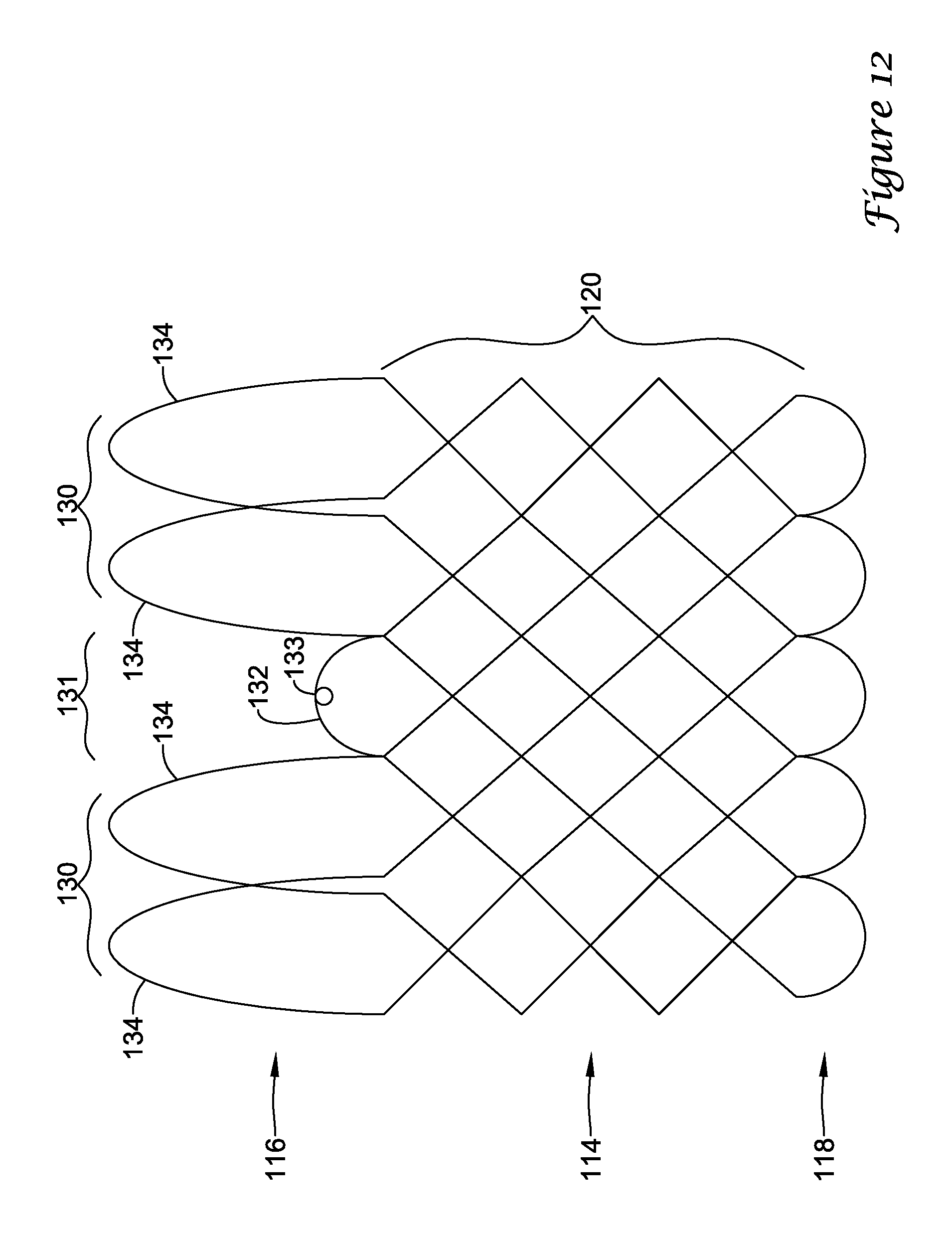
D00014
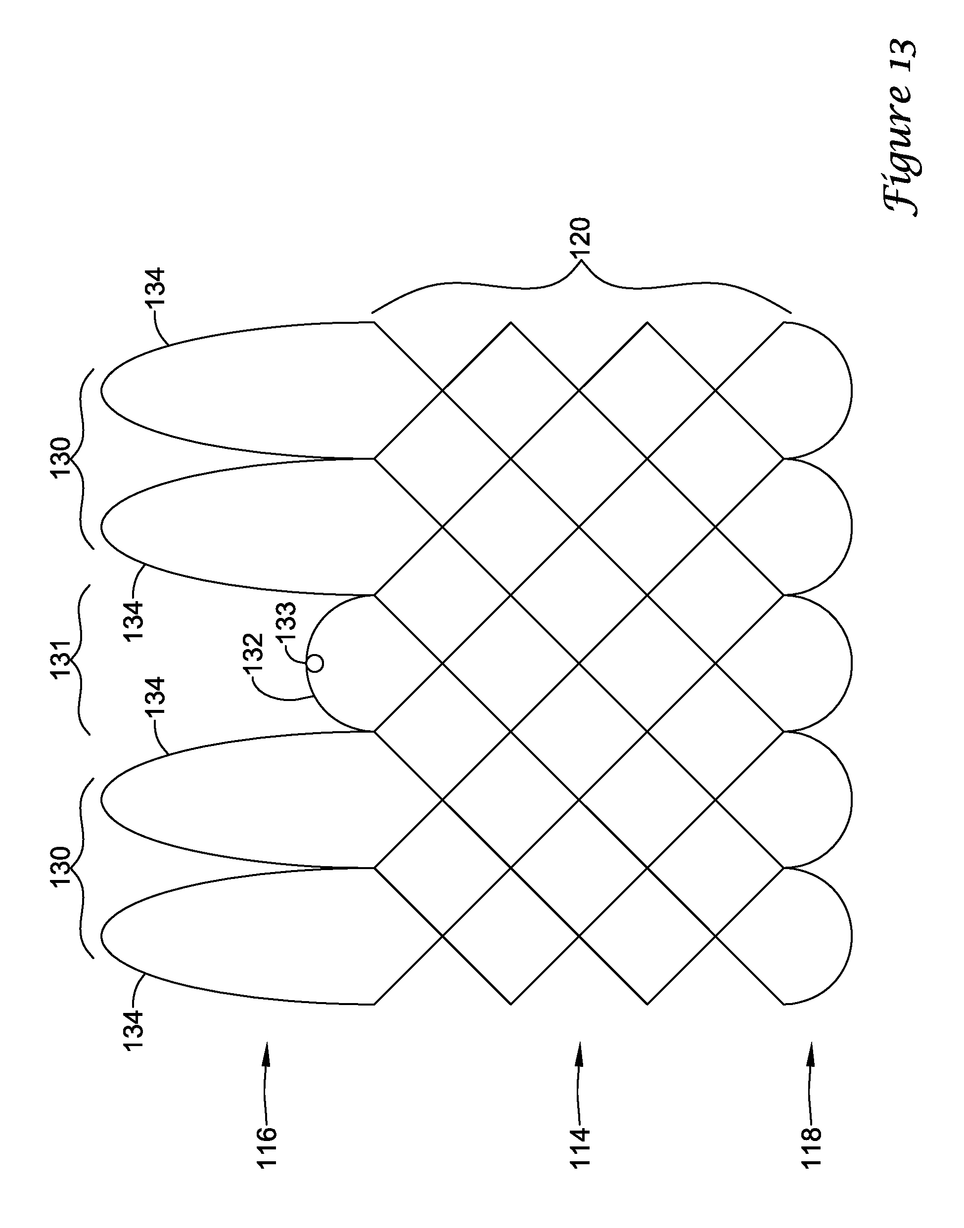
D00015
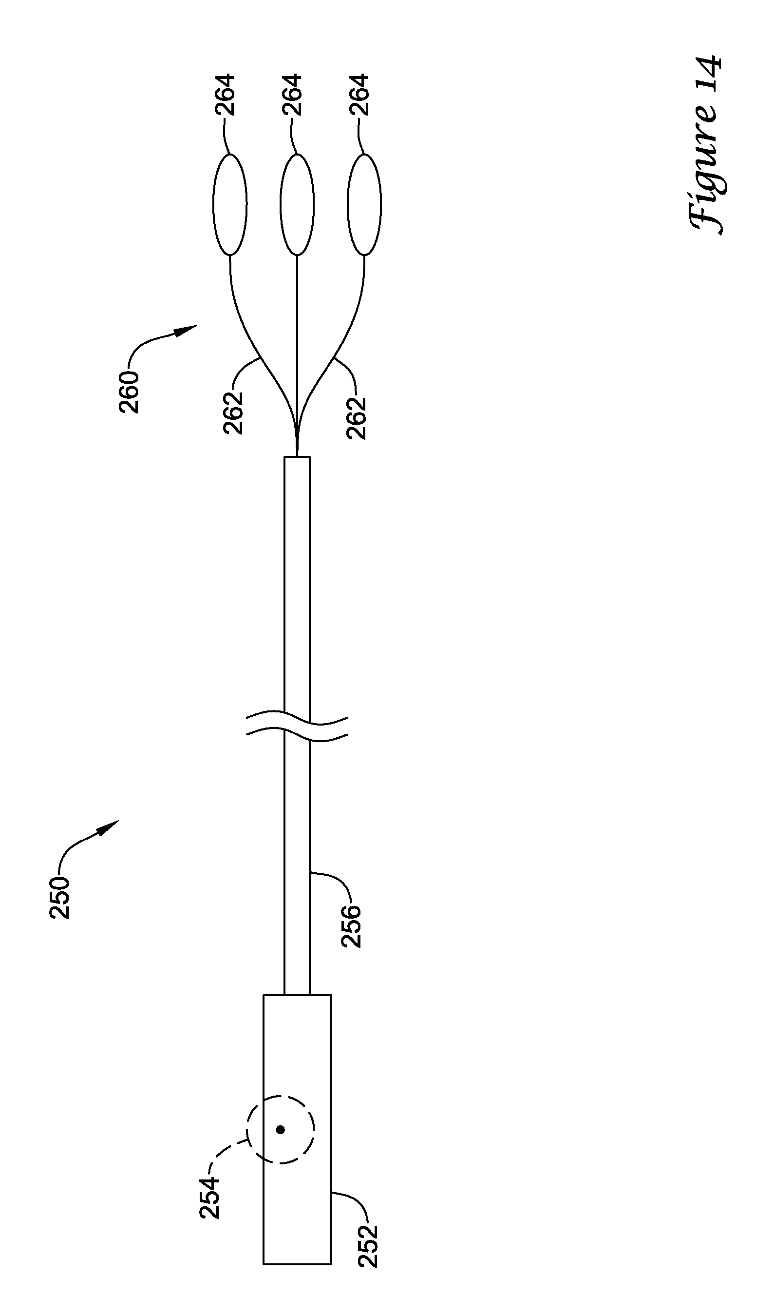
D00016
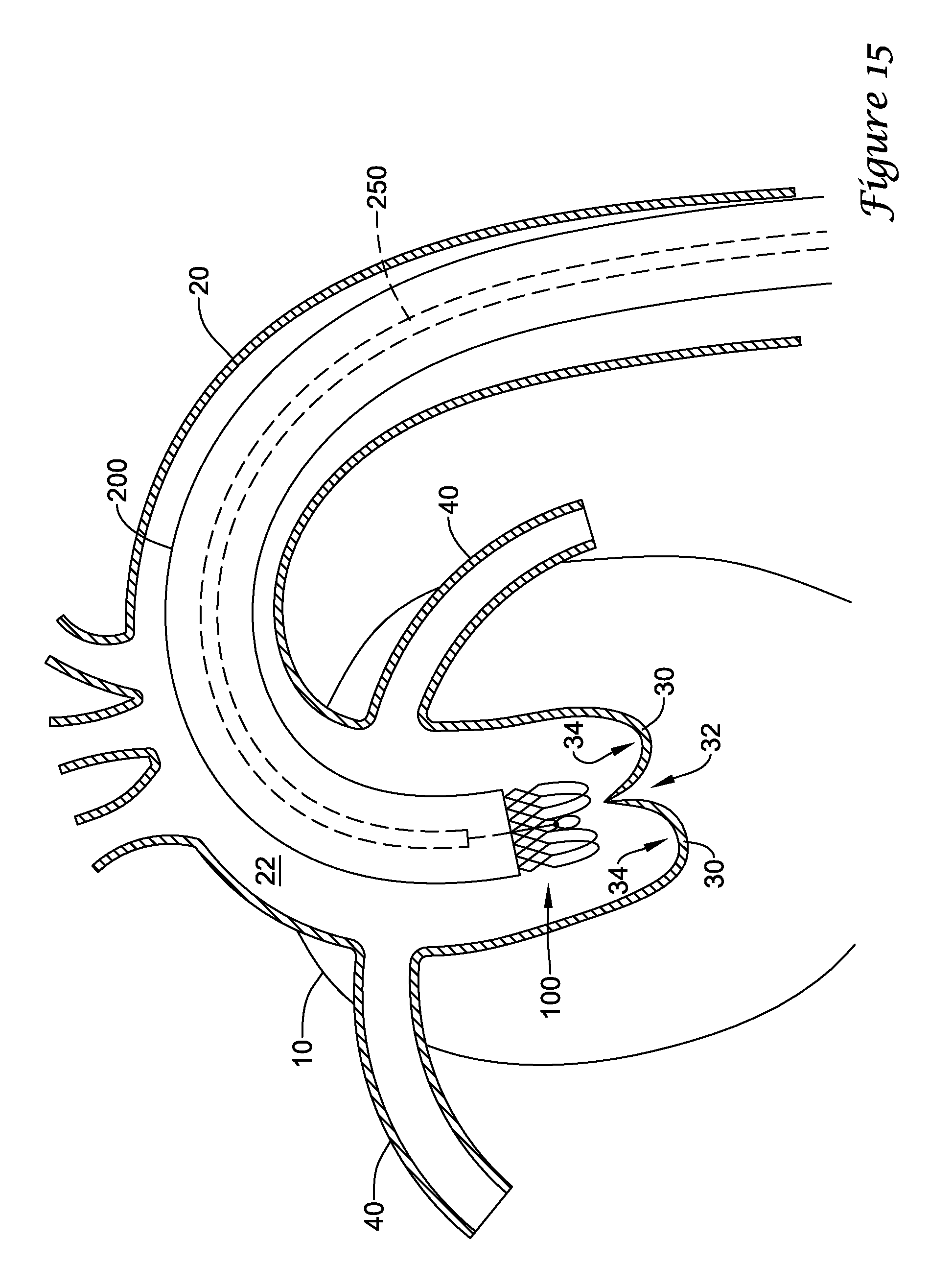
D00017

D00018
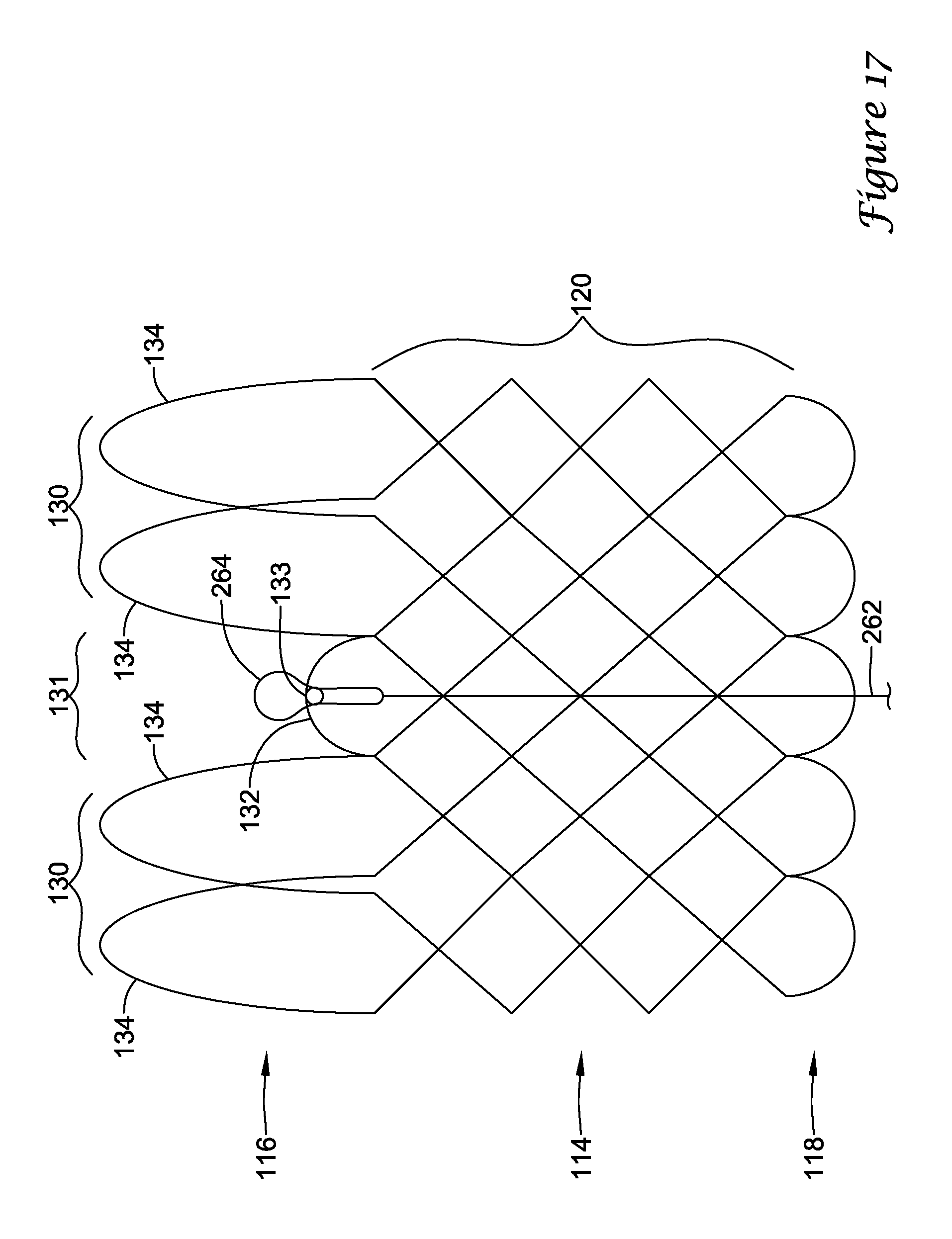
D00019

D00020
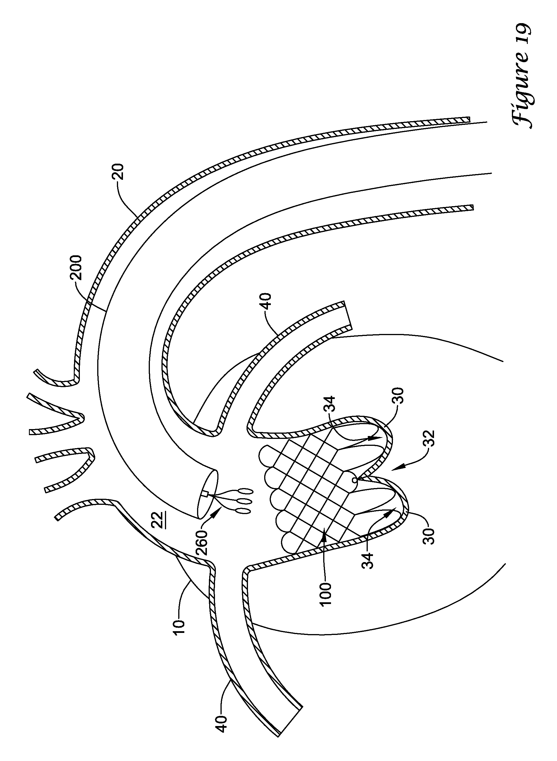
D00021

D00022

XML
uspto.report is an independent third-party trademark research tool that is not affiliated, endorsed, or sponsored by the United States Patent and Trademark Office (USPTO) or any other governmental organization. The information provided by uspto.report is based on publicly available data at the time of writing and is intended for informational purposes only.
While we strive to provide accurate and up-to-date information, we do not guarantee the accuracy, completeness, reliability, or suitability of the information displayed on this site. The use of this site is at your own risk. Any reliance you place on such information is therefore strictly at your own risk.
All official trademark data, including owner information, should be verified by visiting the official USPTO website at www.uspto.gov. This site is not intended to replace professional legal advice and should not be used as a substitute for consulting with a legal professional who is knowledgeable about trademark law.