Surgical apparatus
Cappola , et al.
U.S. patent number 10,285,698 [Application Number 14/812,143] was granted by the patent office on 2019-05-14 for surgical apparatus. This patent grant is currently assigned to Covidien LP. The grantee listed for this patent is Covidien LP. Invention is credited to Kenneth Cappola, Frank Maffei, Lee Ann Olson.


View All Diagrams
| United States Patent | 10,285,698 |
| Cappola , et al. | May 14, 2019 |
Surgical apparatus
Abstract
A surgical apparatus including a tool assembly is provided. The tool assembly includes a chip assembly, a staple cartridge body, a support plate, and a jaw member. The chip assembly includes a first projection facilitating alignment and connection with a connector assembly of the jaw. The chip assembly further includes a second projection received in a recess in the staple cartridge body. The connector assembly and chip assembly include an electrical connection therebetween.
| Inventors: | Cappola; Kenneth (Monroe, CT), Olson; Lee Ann (Wallingford, CT), Maffei; Frank (Shelton, CT) | ||||||||||
|---|---|---|---|---|---|---|---|---|---|---|---|
| Applicant: |
|
||||||||||
| Assignee: | Covidien LP (Mansfield,
MA) |
||||||||||
| Family ID: | 55587017 | ||||||||||
| Appl. No.: | 14/812,143 | ||||||||||
| Filed: | July 29, 2015 |
Prior Publication Data
| Document Identifier | Publication Date | |
|---|---|---|
| US 20160249929 A1 | Sep 1, 2016 | |
Related U.S. Patent Documents
| Application Number | Filing Date | Patent Number | Issue Date | ||
|---|---|---|---|---|---|
| 62121049 | Feb 26, 2015 | ||||
| Current U.S. Class: | 1/1 |
| Current CPC Class: | A61B 90/98 (20160201); A61B 17/068 (20130101); A61B 17/07207 (20130101); A61B 90/90 (20160201); A61B 17/105 (20130101); A61B 2017/00473 (20130101); A61B 2017/00398 (20130101); A61B 2017/07271 (20130101); A61B 2090/0808 (20160201); A61B 2017/00951 (20130101); A61B 2017/2927 (20130101); A61B 2017/00477 (20130101); A61B 2090/038 (20160201); A61B 2017/07278 (20130101); A61B 2017/07285 (20130101) |
| Current International Class: | A61B 17/10 (20060101); A61B 90/90 (20160101); A61B 90/98 (20160101); A61B 17/068 (20060101); A61B 17/072 (20060101); A61B 17/29 (20060101); A61B 90/00 (20160101); A61B 17/00 (20060101) |
| Field of Search: | ;227/175.1-182.1 |
References Cited [Referenced By]
U.S. Patent Documents
| 3079606 | March 1963 | Bobrov et al. |
| 3490675 | January 1970 | Green et al. |
| 3499591 | March 1970 | Green |
| 3777538 | December 1973 | Weatherly et al. |
| 3882854 | May 1975 | Hulka et al. |
| 4027510 | June 1977 | Hiltebrandt |
| 4086926 | May 1978 | Green et al. |
| 4241861 | December 1980 | Fleischer |
| 4244372 | January 1981 | Kapitanov et al. |
| 4429695 | February 1984 | Green |
| 4505414 | March 1985 | Filipi |
| 4520817 | June 1985 | Green |
| 4589413 | May 1986 | Malyshev et al. |
| 4596351 | June 1986 | Fedotov et al. |
| 4602634 | July 1986 | Barkley |
| 4605001 | August 1986 | Rothfuss et al. |
| 4608981 | September 1986 | Rothfuss et al. |
| 4610383 | September 1986 | Rothfuss et al. |
| 4633861 | January 1987 | Chow et al. |
| 4633874 | January 1987 | Chow et al. |
| 4671445 | June 1987 | Barker et al. |
| 4700703 | October 1987 | Resnick et al. |
| 4703887 | November 1987 | Clanton et al. |
| 4728020 | March 1988 | Green et al. |
| 4752024 | June 1988 | Green et al. |
| 4784137 | November 1988 | Kulik et al. |
| 4863088 | September 1989 | Redmond et al. |
| 4869415 | September 1989 | Fox |
| 4892244 | January 1990 | Fox et al. |
| 4955959 | September 1990 | Tompkins et al. |
| 4978049 | December 1990 | Green |
| 4991764 | February 1991 | Mericle |
| 5014899 | May 1991 | Presty et al. |
| 5031814 | July 1991 | Tompkins et al. |
| 5040715 | August 1991 | Green et al. |
| 5065929 | November 1991 | Schulze et al. |
| 5071430 | December 1991 | de Salis et al. |
| 5074454 | December 1991 | Peters |
| 5083695 | January 1992 | Foslien et al. |
| 5084057 | January 1992 | Green et al. |
| 5106008 | April 1992 | Tompkins et al. |
| 5111987 | May 1992 | Moeinzadeh et al. |
| 5129570 | July 1992 | Schulze et al. |
| 5141144 | August 1992 | Foslien et al. |
| 5156315 | October 1992 | Green et al. |
| 5156614 | October 1992 | Green et al. |
| 5163943 | November 1992 | Mohiuddin et al. |
| 5170925 | December 1992 | Madden et al. |
| 5171247 | December 1992 | Hughett et al. |
| 5173133 | December 1992 | Morin et al. |
| 5180092 | January 1993 | Crainich |
| 5188274 | February 1993 | Moeinzadeh et al. |
| 5220928 | June 1993 | Oddsen et al. |
| 5221036 | June 1993 | Takase |
| 5242457 | September 1993 | Akopov et al. |
| 5246156 | September 1993 | Rothfuss et al. |
| 5253793 | October 1993 | Green et al. |
| 5263629 | November 1993 | Trumbull et al. |
| RE34519 | January 1994 | Fox et al. |
| 5275323 | January 1994 | Schulze et al. |
| 5282807 | February 1994 | Knoepfler |
| 5289963 | March 1994 | McGarry et al. |
| 5307976 | May 1994 | Olson et al. |
| 5308576 | May 1994 | Green et al. |
| 5312023 | May 1994 | Green et al. |
| 5318221 | June 1994 | Green et al. |
| 5326013 | July 1994 | Green et al. |
| 5328077 | July 1994 | Lou |
| 5330486 | July 1994 | Wilk |
| 5332142 | July 1994 | Robinson et al. |
| 5336232 | August 1994 | Green et al. |
| 5344061 | September 1994 | Crainich |
| 5352238 | October 1994 | Green et al. |
| 5356064 | October 1994 | Green et al. |
| 5358506 | October 1994 | Green et al. |
| 5364001 | November 1994 | Bryan |
| 5364002 | November 1994 | Green et al. |
| 5364003 | November 1994 | Williamson, IV |
| 5366133 | November 1994 | Geiste |
| 5376095 | December 1994 | Ortiz |
| 5379933 | January 1995 | Green et al. |
| 5381943 | January 1995 | Allen et al. |
| 5382255 | January 1995 | Castro et al. |
| 5383880 | January 1995 | Hooven |
| 5389098 | February 1995 | Tsuruta et al. |
| 5395033 | March 1995 | Byrne et al. |
| 5395034 | March 1995 | Allen et al. |
| 5397046 | March 1995 | Savage et al. |
| 5397324 | March 1995 | Carroll et al. |
| 5403312 | April 1995 | Yates et al. |
| 5405072 | April 1995 | Zlock et al. |
| 5407293 | April 1995 | Crainich |
| 5413268 | May 1995 | Green et al. |
| 5415334 | May 1995 | Williamson et al. |
| 5415335 | May 1995 | Knodell, Jr. |
| 5417361 | May 1995 | Williamson, IV |
| 5423471 | June 1995 | Mastri et al. |
| 5425745 | June 1995 | Green et al. |
| 5431322 | July 1995 | Green et al. |
| 5431323 | July 1995 | Smith et al. |
| 5433721 | July 1995 | Hooven et al. |
| 5441193 | August 1995 | Gravener |
| 5445304 | August 1995 | Plyley et al. |
| 5447265 | September 1995 | Vidal et al. |
| 5452837 | September 1995 | Williamson, IV et al. |
| 5456401 | October 1995 | Green et al. |
| 5464300 | November 1995 | Crainich |
| 5465895 | November 1995 | Knodel et al. |
| 5467911 | November 1995 | Tsuruta et al. |
| 5470007 | November 1995 | Plyley et al. |
| 5470010 | November 1995 | Rothfuss et al. |
| 5472132 | December 1995 | Savage et al. |
| 5474566 | December 1995 | Alesi et al. |
| 5476206 | December 1995 | Green et al. |
| 5478003 | December 1995 | Green et al. |
| 5480089 | January 1996 | Blewett |
| 5482197 | January 1996 | Green et al. |
| 5484095 | January 1996 | Green et al. |
| 5484451 | January 1996 | Akopov et al. |
| 5485947 | January 1996 | Olson et al. |
| 5485952 | January 1996 | Fontayne |
| 5486185 | January 1996 | Freitas et al. |
| 5487499 | January 1996 | Sorrentino et al. |
| 5487500 | January 1996 | Knodel et al. |
| 5489058 | February 1996 | Plyley et al. |
| 5490856 | February 1996 | Person et al. |
| 5497933 | March 1996 | DeFonzo et al. |
| 5501689 | March 1996 | Green et al. |
| 5505363 | April 1996 | Green et al. |
| 5507426 | April 1996 | Young et al. |
| 5518163 | May 1996 | Hooven |
| 5518164 | May 1996 | Hooven |
| 5529235 | June 1996 | Boiarski et al. |
| 5531744 | July 1996 | Nardella et al. |
| 5535934 | July 1996 | Boiarski et al. |
| 5535935 | July 1996 | Vidal et al. |
| 5535937 | July 1996 | Boiarski et al. |
| 5540375 | July 1996 | Bolanos et al. |
| 5542594 | August 1996 | McKean et al. |
| 5549628 | August 1996 | Cooper et al. |
| 5551622 | September 1996 | Yoon |
| 5553765 | September 1996 | Knodel et al. |
| 5554164 | September 1996 | Wilson et al. |
| 5554169 | September 1996 | Green et al. |
| 5560530 | October 1996 | Bolanos et al. |
| 5560532 | October 1996 | DeFonzo et al. |
| 5562239 | October 1996 | Boiarski et al. |
| 5562241 | October 1996 | Knodel et al. |
| 5562682 | October 1996 | Oberlin et al. |
| 5562701 | October 1996 | Huiterna et al. |
| 5564615 | October 1996 | Bishop et al. |
| 5571116 | November 1996 | Bolanos et al. |
| 5573169 | November 1996 | Green et al. |
| 5573543 | November 1996 | Akopov et al. |
| 5575799 | November 1996 | Bolanos et al. |
| 5575803 | November 1996 | Cooper et al. |
| 5577654 | November 1996 | Bishop |
| 5579107 | November 1996 | Wright et al. |
| 5584425 | December 1996 | Savage et al. |
| 5586711 | December 1996 | Plyley et al. |
| 5588580 | December 1996 | Paul et al. |
| 5588581 | December 1996 | Conlon et al. |
| 5597107 | January 1997 | Knodel et al. |
| 5601224 | February 1997 | Bishop et al. |
| 5607095 | March 1997 | Smith et al. |
| 5615820 | April 1997 | Viola |
| 5618291 | April 1997 | Thompson et al. |
| 5624452 | April 1997 | Yates |
| 5626587 | May 1997 | Bishop et al. |
| 5628446 | May 1997 | Geiste et al. |
| 5630539 | May 1997 | Plyley et al. |
| 5630540 | May 1997 | Blewett |
| 5630541 | May 1997 | Williamson, IV et al. |
| 5632432 | May 1997 | Schulze et al. |
| 5634584 | June 1997 | Okorocha et al. |
| 5636780 | June 1997 | Green et al. |
| 5645209 | July 1997 | Green et al. |
| 5647526 | July 1997 | Green et al. |
| 5651491 | July 1997 | Heaton et al. |
| 5653373 | August 1997 | Green et al. |
| 5653374 | August 1997 | Young et al. |
| 5653721 | August 1997 | Knodel et al. |
| 5655698 | August 1997 | Yoon |
| 5657921 | August 1997 | Young et al. |
| 5658300 | August 1997 | Bito et al. |
| 5662258 | September 1997 | Knodel et al. |
| 5662259 | September 1997 | Yoon |
| 5662260 | September 1997 | Yoon |
| 5662662 | September 1997 | Bishop et al. |
| 5662666 | September 1997 | Onuki et al. |
| 5665085 | September 1997 | Nardella |
| 5667517 | September 1997 | Hooven |
| 5669544 | September 1997 | Schulze et al. |
| 5673840 | October 1997 | Schulze et al. |
| 5673841 | October 1997 | Schulze et al. |
| 5673842 | October 1997 | Bittner et al. |
| 5676674 | October 1997 | Bolanos et al. |
| 5680981 | October 1997 | Mililli et al. |
| 5680982 | October 1997 | Schulze et al. |
| 5680983 | October 1997 | Plyley et al. |
| 5690269 | November 1997 | Bolanos et al. |
| 5692668 | December 1997 | Schulze et al. |
| 5697542 | December 1997 | Knodel et al. |
| 5702409 | December 1997 | Rayburn et al. |
| 5704534 | January 1998 | Huitema et al. |
| 5706997 | January 1998 | Green et al. |
| 5709334 | January 1998 | Sorrentino et al. |
| 5711472 | January 1998 | Bryan |
| 5713505 | February 1998 | Huitema |
| 5715988 | February 1998 | Palmer |
| 5716366 | February 1998 | Yates |
| 5718359 | February 1998 | Palmer et al. |
| 5725536 | March 1998 | Oberlin et al. |
| 5725554 | March 1998 | Simon et al. |
| 5728110 | March 1998 | Vidal et al. |
| 5732806 | March 1998 | Foshee et al. |
| 5735848 | April 1998 | Yates et al. |
| 5743456 | April 1998 | Jones et al. |
| 5749893 | May 1998 | Vidal et al. |
| 5752644 | May 1998 | Bolanos et al. |
| 5762255 | June 1998 | Chrisman et al. |
| 5762256 | June 1998 | Mastri et al. |
| 5769303 | June 1998 | Knodel et al. |
| 5769892 | June 1998 | Kingwell |
| 5772099 | June 1998 | Gravener |
| 5772673 | June 1998 | Cuny et al. |
| 5779130 | July 1998 | Alesi et al. |
| 5779131 | July 1998 | Knodel et al. |
| 5779132 | July 1998 | Knodel et al. |
| 5782396 | July 1998 | Mastri et al. |
| 5782397 | July 1998 | Koukline |
| 5782834 | July 1998 | Lucey et al. |
| 5785232 | July 1998 | Vidal et al. |
| 5797536 | August 1998 | Smith et al. |
| 5797537 | August 1998 | Oberlin et al. |
| 5797538 | August 1998 | Heaton et al. |
| 5810811 | September 1998 | Yates et al. |
| 5810855 | September 1998 | Rayburn et al. |
| 5814055 | September 1998 | Knodel et al. |
| 5814057 | September 1998 | Oi et al. |
| 5816471 | October 1998 | Plyley et al. |
| 5817109 | October 1998 | McGarry et al. |
| 5820009 | October 1998 | Melling et al. |
| 5823066 | October 1998 | Huitema et al. |
| 5826776 | October 1998 | Schulze et al. |
| 5829662 | November 1998 | Allen et al. |
| 5833695 | November 1998 | Yoon |
| 5836147 | November 1998 | Schnipke |
| 5862972 | January 1999 | Green et al. |
| 5865361 | February 1999 | Milliman et al. |
| 5871135 | February 1999 | Williamson, IV et al. |
| 5873873 | February 1999 | Smith et al. |
| 5878938 | March 1999 | Bittner et al. |
| 5893506 | April 1999 | Powell |
| 5894979 | April 1999 | Powell |
| 5897562 | April 1999 | Bolanos et al. |
| 5901895 | May 1999 | Heaton et al. |
| 5911352 | June 1999 | Racenet et al. |
| 5911353 | June 1999 | Bolanos et al. |
| 5918791 | July 1999 | Sorrentino et al. |
| 5919198 | July 1999 | Graves, Jr. et al. |
| 5922001 | July 1999 | Yoon |
| 5931847 | August 1999 | Bittner et al. |
| 5934139 | August 1999 | Tucker |
| 5941442 | August 1999 | Geiste et al. |
| 5954259 | September 1999 | Viola et al. |
| 5964774 | October 1999 | McKean et al. |
| 5980510 | November 1999 | Tsonton et al. |
| 5988479 | November 1999 | Palmer |
| 6004335 | December 1999 | Vaitekunas et al. |
| 6010054 | January 2000 | Johnson et al. |
| 6032849 | March 2000 | Mastri et al. |
| 6045560 | April 2000 | McKean et al. |
| 6063097 | May 2000 | Oi et al. |
| 6079606 | June 2000 | Milliman et al. |
| 6099551 | August 2000 | Gabbay |
| 6109500 | August 2000 | Alli et al. |
| 6131789 | October 2000 | Schulze et al. |
| 6131790 | October 2000 | Piraka |
| 6155473 | December 2000 | Tompkins et al. |
| 6197017 | March 2001 | Brock et al. |
| 6202914 | March 2001 | Geiste et al. |
| 6241139 | June 2001 | Milliman et al. |
| 6250532 | June 2001 | Green et al. |
| 6264086 | July 2001 | McGuckin, Jr. |
| 6264087 | July 2001 | Whitman |
| 6269977 | August 2001 | Moore |
| 6279809 | August 2001 | Nicolo |
| 6315183 | November 2001 | Piraka |
| 6315184 | November 2001 | Whitman |
| 6325810 | December 2001 | Hamilton et al. |
| 6330965 | December 2001 | Milliman et al. |
| 6391038 | May 2002 | Vargas et al. |
| 6398797 | June 2002 | Bombard et al. |
| 6436097 | August 2002 | Nardella |
| 6439446 | August 2002 | Perry et al. |
| 6443973 | September 2002 | Whitman |
| 6463623 | October 2002 | Ahn et al. |
| 6478804 | November 2002 | Vargas et al. |
| 6488196 | December 2002 | Fenton, Jr. |
| 6503257 | January 2003 | Grant et al. |
| 6505768 | January 2003 | Whitman |
| 6544274 | April 2003 | Danitz et al. |
| 6554844 | April 2003 | Lee et al. |
| 6565554 | May 2003 | Niemeyer |
| 6587750 | July 2003 | Gerbi et al. |
| 6592597 | July 2003 | Grant et al. |
| 6594552 | July 2003 | Nowlin et al. |
| 6602252 | August 2003 | Mollenauer |
| 6612053 | September 2003 | Liao |
| 6619529 | September 2003 | Green et al. |
| D480808 | October 2003 | Wells et al. |
| 6644532 | November 2003 | Green et al. |
| 6656193 | December 2003 | Grant et al. |
| 6669073 | December 2003 | Milliman et al. |
| 6681978 | January 2004 | Geiste et al. |
| 6698643 | March 2004 | Whitman |
| 6716232 | April 2004 | Vidal et al. |
| 6722552 | April 2004 | Fenton, Jr. |
| 6731473 | May 2004 | Li et al. |
| 6755338 | June 2004 | Hahnen et al. |
| 6783524 | August 2004 | Anderson et al. |
| 6786382 | September 2004 | Hoffman |
| 6808262 | October 2004 | Chapoy et al. |
| 6817509 | November 2004 | Geiste et al. |
| 6830174 | December 2004 | Hillstead et al. |
| 6835199 | December 2004 | McGuckin, Jr. et al. |
| 6843403 | January 2005 | Whitman |
| RE38708 | March 2005 | Bolanos et al. |
| 6877647 | April 2005 | Green et al. |
| 6889116 | May 2005 | Jinno |
| 6905057 | June 2005 | Swayze et al. |
| 6945444 | September 2005 | Gresham et al. |
| 6953138 | October 2005 | Dworak et al. |
| 6953139 | October 2005 | Milliman et al. |
| 6959852 | November 2005 | Shelton, IV et al. |
| 6962594 | November 2005 | Thevenet |
| 6964363 | November 2005 | Wales et al. |
| 6978921 | December 2005 | Shelton, IV et al. |
| 6981628 | January 2006 | Wales |
| 6986451 | January 2006 | Mastri et al. |
| 6988649 | January 2006 | Shelton, IV et al. |
| 6991627 | January 2006 | Madhani et al. |
| 6994714 | February 2006 | Vargas et al. |
| 7000818 | February 2006 | Shelton, IV et al. |
| 7000819 | February 2006 | Swayze et al. |
| 7032799 | April 2006 | Viola et al. |
| 7044352 | May 2006 | Shelton, IV et al. |
| 7044353 | May 2006 | Mastri et al. |
| 7055730 | June 2006 | Ehrenfels et al. |
| 7055731 | June 2006 | Shelton, IV et al. |
| 7059508 | June 2006 | Shelton, IV et al. |
| 7070083 | July 2006 | Jankowski |
| 7083075 | August 2006 | Swayze et al. |
| 7097089 | August 2006 | Marczyk |
| 7111769 | September 2006 | Wales et al. |
| 7114642 | October 2006 | Whitman |
| 7121446 | October 2006 | Arad et al. |
| 7128253 | October 2006 | Mastri et al. |
| 7128254 | October 2006 | Shelton, IV et al. |
| 7140527 | November 2006 | Ehrenfels et al. |
| 7140528 | November 2006 | Shelton, IV |
| 7143923 | December 2006 | Shelton, IV et al. |
| 7143924 | December 2006 | Scirica et al. |
| 7143925 | December 2006 | Shelton, IV et al. |
| 7143926 | December 2006 | Shelton, IV et al. |
| 7147138 | December 2006 | Shelton, IV |
| 7159750 | January 2007 | Racenet et al. |
| 7168604 | January 2007 | Milliman et al. |
| 7172104 | February 2007 | Scirica et al. |
| 7188758 | March 2007 | Viola et al. |
| 7207471 | April 2007 | Heinrich et al. |
| 7213736 | May 2007 | Wales et al. |
| 7225963 | June 2007 | Scirica |
| 7225964 | June 2007 | Mastri et al. |
| 7238195 | July 2007 | Viola |
| 7246734 | July 2007 | Shelton, IV |
| 7258262 | August 2007 | Mastri et al. |
| 7278562 | October 2007 | Mastri et al. |
| 7278563 | October 2007 | Green |
| 7287682 | October 2007 | Ezzat et al. |
| 7293685 | November 2007 | Ehrenfels et al. |
| 7296722 | November 2007 | Ivanko |
| 7296724 | November 2007 | Green et al. |
| 7296772 | November 2007 | Wang |
| 7300444 | November 2007 | Nielsen et al. |
| 7303107 | December 2007 | Milliman et al. |
| 7303108 | December 2007 | Shelton, IV |
| 7308998 | December 2007 | Mastri et al. |
| 7326232 | February 2008 | Viola et al. |
| 7328828 | February 2008 | Ortiz et al. |
| 7328829 | February 2008 | Arad et al. |
| 7334717 | February 2008 | Rethy et al. |
| 7354447 | April 2008 | Shelton, IV et al. |
| 7357287 | April 2008 | Shelton, IV et al. |
| 7364061 | April 2008 | Swayze et al. |
| 7367485 | May 2008 | Shelton, IV et al. |
| 7377928 | May 2008 | Zubik et al. |
| 7380695 | June 2008 | Doll et al. |
| 7380696 | June 2008 | Shelton, IV et al. |
| 7396356 | July 2008 | Mollenauer |
| 7398907 | July 2008 | Racenet et al. |
| 7399310 | July 2008 | Edoga et al. |
| 7401720 | July 2008 | Durrani |
| 7401721 | July 2008 | Holsten et al. |
| 7404508 | July 2008 | Smith et al. |
| 7404509 | July 2008 | Ortiz et al. |
| 7407074 | August 2008 | Ortiz et al. |
| 7407075 | August 2008 | Holsten et al. |
| 7407077 | August 2008 | Ortiz et al. |
| 7407078 | August 2008 | Shelton, IV et al. |
| 7416101 | August 2008 | Shelton, IV et al. |
| 7419080 | September 2008 | Smith et al. |
| 7419081 | September 2008 | Ehrenfels et al. |
| 7419495 | September 2008 | Menn et al. |
| 7422139 | September 2008 | Shelton, IV et al. |
| 7424965 | September 2008 | Racenet et al. |
| 7431189 | October 2008 | Shelton, IV et al. |
| 7431730 | October 2008 | Viola |
| 7434715 | October 2008 | Shelton, IV et al. |
| 7434717 | October 2008 | Shelton, IV et al. |
| 7438208 | October 2008 | Larson |
| 7438209 | October 2008 | Hess et al. |
| 7441684 | October 2008 | Shelton, IV et al. |
| 7441685 | October 2008 | Boudreaux |
| 7448525 | November 2008 | Shelton, IV et al. |
| 7451904 | November 2008 | Shelton, IV |
| 7455208 | November 2008 | Wales et al. |
| 7455676 | November 2008 | Holsten et al. |
| 7458494 | December 2008 | Matsutani et al. |
| 7461767 | December 2008 | Viola et al. |
| 7462185 | December 2008 | Knodel |
| 7464846 | December 2008 | Shelton, IV et al. |
| 7464847 | December 2008 | Viola et al. |
| 7464848 | December 2008 | Green et al. |
| 7464849 | December 2008 | Shelton, IV et al. |
| 7467740 | December 2008 | Shelton, IV et al. |
| 7472814 | January 2009 | Mastri et al. |
| 7472815 | January 2009 | Shelton, IV et al. |
| 7472816 | January 2009 | Holsten et al. |
| 7473258 | January 2009 | Clauson et al. |
| 7481347 | January 2009 | Roy |
| 7481348 | January 2009 | Marczyk |
| 7481349 | January 2009 | Holsten et al. |
| 7481824 | January 2009 | Boudreaux et al. |
| 7487899 | February 2009 | Shelton, IV et al. |
| 7490749 | February 2009 | Schall et al. |
| 7494039 | February 2009 | Racenet et al. |
| 7500979 | March 2009 | Hueil et al. |
| 7503474 | March 2009 | Hillstead et al. |
| 7506790 | March 2009 | Shelton, IV |
| 7506791 | March 2009 | Omaits et al. |
| 7510107 | March 2009 | Timm et al. |
| 7513408 | April 2009 | Shelton, IV et al. |
| 7517356 | April 2009 | Heinrich |
| 7537602 | May 2009 | Whitman |
| 7543729 | June 2009 | Ivanko |
| 7543730 | June 2009 | Marczyk |
| 7543731 | June 2009 | Green et al. |
| 7552854 | June 2009 | Wixey et al. |
| 7556185 | July 2009 | Viola |
| 7556186 | July 2009 | Milliman |
| 7559450 | July 2009 | Wales et al. |
| 7559452 | July 2009 | Wales et al. |
| 7559453 | July 2009 | Heinrich et al. |
| 7559937 | July 2009 | de la Torre et al. |
| 7565993 | July 2009 | Milliman et al. |
| 7568603 | August 2009 | Shelton, IV et al. |
| 7568604 | August 2009 | Ehrenfels et al. |
| 7571845 | August 2009 | Viola |
| 7575144 | August 2009 | Ortiz et al. |
| 7584880 | September 2009 | Racenet et al. |
| 7588174 | September 2009 | Holsten et al. |
| 7588175 | September 2009 | Timm et al. |
| 7588176 | September 2009 | Timm et al. |
| 7588177 | September 2009 | Racenet |
| 7597229 | October 2009 | Boudreaux et al. |
| 7597230 | October 2009 | Racenet et al. |
| 7600663 | October 2009 | Green |
| 7604150 | October 2009 | Boudreaux |
| 7604151 | October 2009 | Hess et al. |
| 7607557 | October 2009 | Shelton, IV et al. |
| 7611038 | November 2009 | Racenet et al. |
| 7617961 | November 2009 | Viola |
| 7624902 | December 2009 | Marczyk et al. |
| 7624903 | December 2009 | Green et al. |
| 7631793 | December 2009 | Rethy et al. |
| 7631794 | December 2009 | Rethy et al. |
| 7635073 | December 2009 | Heinrich |
| 7635074 | December 2009 | Olson et al. |
| 7635373 | December 2009 | Ortiz |
| 7637409 | December 2009 | Marczyk |
| 7637410 | December 2009 | Marczyk |
| 7641091 | January 2010 | Olson et al. |
| 7641095 | January 2010 | Viola |
| 7644848 | January 2010 | Swayze et al. |
| 7648055 | January 2010 | Marczyk |
| 7651017 | January 2010 | Ortiz et al. |
| 7654431 | February 2010 | Hueil et al. |
| 7658311 | February 2010 | Boudreaux |
| 7658312 | February 2010 | Vidal et al. |
| 7665646 | February 2010 | Prommersberger |
| 7665647 | February 2010 | Shelton, IV et al. |
| 7669746 | March 2010 | Shelton, IV |
| 7670334 | March 2010 | Hueil et al. |
| 7673780 | March 2010 | Shelton, IV et al. |
| 7673781 | March 2010 | Swayze et al. |
| 7673782 | March 2010 | Hess et al. |
| 7673783 | March 2010 | Morgan et al. |
| 7678121 | March 2010 | Knodel |
| 7681772 | March 2010 | Green et al. |
| 7682367 | March 2010 | Shah et al. |
| 7682368 | March 2010 | Bombard et al. |
| 7690547 | April 2010 | Racenet et al. |
| 7694865 | April 2010 | Scirica |
| 7699205 | April 2010 | Ivanko |
| 7703653 | April 2010 | Shah et al. |
| 7721931 | May 2010 | Shelton, IV et al. |
| 7721933 | May 2010 | Ehrenfels et al. |
| 7721935 | May 2010 | Racenet et al. |
| 7726537 | June 2010 | Olson et al. |
| 7726538 | June 2010 | Holsten et al. |
| 7726539 | June 2010 | Holsten et al. |
| 7731072 | June 2010 | Timm et al. |
| 7735703 | June 2010 | Morgan et al. |
| 7740159 | June 2010 | Shelton, IV et al. |
| 7740160 | June 2010 | Viola |
| 7743960 | June 2010 | Whitman et al. |
| 7744628 | June 2010 | Viola |
| 7753245 | July 2010 | Boudreaux et al. |
| 7753248 | July 2010 | Viola |
| 7757924 | July 2010 | Gerbi et al. |
| 7757925 | July 2010 | Viola et al. |
| 7762445 | July 2010 | Heinrich et al. |
| 7766209 | August 2010 | Baxter, III et al. |
| 7766210 | August 2010 | Shelton, IV et al. |
| 7766924 | August 2010 | Bombard et al. |
| 7766928 | August 2010 | Ezzat et al. |
| 7770774 | August 2010 | Mastri et al. |
| 7770775 | August 2010 | Shelton, IV et al. |
| 7776060 | August 2010 | Mooradian et al. |
| 7780055 | August 2010 | Scirica et al. |
| 7784662 | August 2010 | Wales et al. |
| 7789283 | September 2010 | Shah |
| 7789889 | September 2010 | Zubik et al. |
| 7793812 | September 2010 | Moore et al. |
| 7793814 | September 2010 | Racenet et al. |
| 7794475 | September 2010 | Hess et al. |
| 7798385 | September 2010 | Boyden et al. |
| 7798386 | September 2010 | Schall et al. |
| 7799039 | September 2010 | Shelton, IV et al. |
| 7810690 | October 2010 | Bilotti et al. |
| 7810692 | October 2010 | Hall et al. |
| 7810693 | October 2010 | Broehl et al. |
| 7815090 | October 2010 | Marczyk |
| 7815091 | October 2010 | Marczyk |
| 7815092 | October 2010 | Whitman et al. |
| 7819296 | October 2010 | Hueil et al. |
| 7819297 | October 2010 | Doll et al. |
| 7819298 | October 2010 | Hall et al. |
| 7819299 | October 2010 | Shelton, IV et al. |
| 7819796 | October 2010 | Blake et al. |
| 7823760 | November 2010 | Zemlok et al. |
| 7823761 | November 2010 | Boyden et al. |
| 7824426 | November 2010 | Racenet et al. |
| 7828186 | November 2010 | Wales |
| 7828187 | November 2010 | Green et al. |
| 7828188 | November 2010 | Jankowski |
| 7828189 | November 2010 | Holsten et al. |
| 7832408 | November 2010 | Shelton, IV et al. |
| 7832611 | November 2010 | Boyden et al. |
| 7832612 | November 2010 | Baxter, III et al. |
| 7837079 | November 2010 | Holsten et al. |
| 7837081 | November 2010 | Holsten et al. |
| 7841503 | November 2010 | Sonnenschein et al. |
| 7845533 | December 2010 | Marczyk et al. |
| 7845534 | December 2010 | Viola et al. |
| 7845535 | December 2010 | Scircia |
| 7845537 | December 2010 | Shelton, IV et al. |
| 7845538 | December 2010 | Whitman |
| 7850703 | December 2010 | Bombard et al. |
| 7857183 | December 2010 | Shelton, IV |
| 7857184 | December 2010 | Viola |
| 7857185 | December 2010 | Swayze et al. |
| 7857186 | December 2010 | Baxter, III et al. |
| 7861906 | January 2011 | Doll et al. |
| 7861907 | January 2011 | Green et al. |
| 7866524 | January 2011 | Krehel |
| 7866525 | January 2011 | Scirica |
| 7866526 | January 2011 | Green et al. |
| 7866527 | January 2011 | Hall et al. |
| 7866528 | January 2011 | Olson et al. |
| 7870989 | January 2011 | Viola et al. |
| 7886952 | February 2011 | Scirica et al. |
| 7891532 | February 2011 | Mastri et al. |
| 7891533 | February 2011 | Green et al. |
| 7891534 | February 2011 | Wenchell et al. |
| 7896214 | March 2011 | Farascioni |
| 7900805 | March 2011 | Shelton, IV et al. |
| 7901416 | March 2011 | Nolan et al. |
| 7905380 | March 2011 | Shelton, IV et al. |
| 7905381 | March 2011 | Baxter, III et al. |
| 7909039 | March 2011 | Hur |
| 7909220 | March 2011 | Viola |
| 7909221 | March 2011 | Viola et al. |
| 7909224 | March 2011 | Prommersberger |
| 7913891 | March 2011 | Doll et al. |
| 7913893 | March 2011 | Mastri et al. |
| 7914543 | March 2011 | Roth et al. |
| 7918230 | April 2011 | Whitman et al. |
| 7918276 | April 2011 | Guignard et al. |
| 7922061 | April 2011 | Shelton, IV et al. |
| 7922063 | April 2011 | Zemlok et al. |
| 7922064 | April 2011 | Boyden et al. |
| 7926691 | April 2011 | Viola et al. |
| 7926692 | April 2011 | Racenet et al. |
| 7934628 | May 2011 | Wenchell et al. |
| 7934630 | May 2011 | Shelton, IV et al. |
| 7934631 | May 2011 | Balbierz et al. |
| 7942300 | May 2011 | Rethy et al. |
| 7942303 | May 2011 | Shah |
| 7950560 | May 2011 | Zemlok et al. |
| 7950561 | May 2011 | Aranyi |
| 7950562 | May 2011 | Beardsley et al. |
| 7954682 | June 2011 | Giordano et al. |
| 7954683 | June 2011 | Knodel et al. |
| 7954684 | June 2011 | Boudreaux |
| 7954685 | June 2011 | Viola |
| 7954686 | June 2011 | Baxter, III et al. |
| 7954687 | June 2011 | Zemlok et al. |
| 7959051 | June 2011 | Smith et al. |
| 7963431 | June 2011 | Scirica |
| 7963432 | June 2011 | Knodel et al. |
| 7963433 | June 2011 | Whitman et al. |
| 7967178 | June 2011 | Scirica et al. |
| 7967179 | June 2011 | Olson et al. |
| 7967180 | June 2011 | Scirica |
| 7975894 | July 2011 | Boyden et al. |
| 7980443 | July 2011 | Scheib et al. |
| 7988026 | August 2011 | Knodel et al. |
| 7988027 | August 2011 | Olson et al. |
| 7988028 | August 2011 | Farascioni et al. |
| 7992758 | August 2011 | Whitman et al. |
| 7997468 | August 2011 | Farascioni |
| 7997469 | August 2011 | Olson et al. |
| 8002795 | August 2011 | Beetel |
| 8006885 | August 2011 | Marczyk |
| 8006887 | August 2011 | Marczyk |
| 8007505 | August 2011 | Weller et al. |
| 8007513 | August 2011 | Nalagatla et al. |
| 8011550 | September 2011 | Aranyi et al. |
| 8011551 | September 2011 | Marczyk et al. |
| 8011552 | September 2011 | Ivanko |
| 8011553 | September 2011 | Mastri et al. |
| 8011555 | September 2011 | Tarinelli et al. |
| 8012170 | September 2011 | Whitman et al. |
| 8015976 | September 2011 | Shah |
| 8016177 | September 2011 | Bettuchi et al. |
| 8016178 | September 2011 | Olson et al. |
| 8020742 | September 2011 | Marczyk |
| 8020743 | September 2011 | Shelton, IV |
| 8028882 | October 2011 | Viola |
| 8028883 | October 2011 | Stopek |
| 8028884 | October 2011 | Sniffin et al. |
| 8033438 | October 2011 | Scirica |
| 8033440 | October 2011 | Wenchell et al. |
| 8033441 | October 2011 | Marczyk |
| 8033442 | October 2011 | Racenet et al. |
| 8034077 | October 2011 | Smith et al. |
| 8038044 | October 2011 | Viola |
| 8038045 | October 2011 | Bettuchi et al. |
| 8052024 | November 2011 | Viola et al. |
| 8056787 | November 2011 | Boudreaux et al. |
| 8056788 | November 2011 | Mastri et al. |
| 8056791 | November 2011 | Whitman |
| 8061577 | November 2011 | Racenet et al. |
| 8066166 | November 2011 | Demmy et al. |
| 8070033 | December 2011 | Milliman et al. |
| 8070034 | December 2011 | Knodel |
| 8070035 | December 2011 | Holsten et al. |
| 8074858 | December 2011 | Marczyk |
| 8074859 | December 2011 | Kostrzewski |
| 8074862 | December 2011 | Shah |
| 8083118 | December 2011 | Milliman et al. |
| 8083119 | December 2011 | Prommersberger |
| 8083120 | December 2011 | Shelton, IV et al. |
| 8087563 | January 2012 | Milliman et al. |
| 8091753 | January 2012 | Viola |
| 8091754 | January 2012 | Ehrenfels et al. |
| 8091756 | January 2012 | Viola |
| 8092493 | January 2012 | Marczyk |
| 8096459 | January 2012 | Ortiz et al. |
| 8096460 | January 2012 | Blier et al. |
| 8100309 | January 2012 | Marczyk |
| 8100310 | January 2012 | Zemlok |
| 8102008 | January 2012 | Wells |
| 8113406 | February 2012 | Holsten et al. |
| 8113407 | February 2012 | Holsten et al. |
| 8113408 | February 2012 | Wenchell et al. |
| 8113409 | February 2012 | Cohen et al. |
| 8113410 | February 2012 | Hall et al. |
| 8123101 | February 2012 | Racenet et al. |
| 8127975 | March 2012 | Olson et al. |
| 8127976 | March 2012 | Scirica et al. |
| 8132703 | March 2012 | Milliman et al. |
| 8132705 | March 2012 | Viola et al. |
| 8132706 | March 2012 | Marczyk et al. |
| 8136713 | March 2012 | Hathaway et al. |
| 8141762 | March 2012 | Bedi et al. |
| 8152041 | April 2012 | Kostrzewski |
| 8157148 | April 2012 | Scirica |
| 8157150 | April 2012 | Viola et al. |
| 8157151 | April 2012 | Ingmanson et al. |
| 8157152 | April 2012 | Holsten et al. |
| 8162197 | April 2012 | Mastri et al. |
| 8167185 | May 2012 | Shelton, IV et al. |
| 8167186 | May 2012 | Racenet et al. |
| 8172121 | May 2012 | Krehel |
| 8172124 | May 2012 | Shelton, IV et al. |
| 8181837 | May 2012 | Roy |
| 8186555 | May 2012 | Shelton, IV et al. |
| 8186557 | May 2012 | Cohen et al. |
| 8186558 | May 2012 | Sapienza |
| 8186559 | May 2012 | Whitman |
| 8186560 | May 2012 | Hess et al. |
| 8193044 | June 2012 | Kenneth |
| 8196795 | June 2012 | Moore et al. |
| 8196796 | June 2012 | Shelton, IV et al. |
| 8201721 | June 2012 | Zemlok et al. |
| 8205619 | June 2012 | Shah et al. |
| 8205780 | June 2012 | Sorrentino et al. |
| 8205781 | June 2012 | Baxter, III et al. |
| 8210412 | July 2012 | Marczyk |
| 8210416 | July 2012 | Milliman et al. |
| 8216236 | July 2012 | Heinrich et al. |
| 8220688 | July 2012 | Laurent et al. |
| 8220690 | July 2012 | Hess et al. |
| 8225979 | July 2012 | Farascioni et al. |
| 8231040 | July 2012 | Zemlok et al. |
| 8231041 | July 2012 | Marczyk et al. |
| 8235272 | August 2012 | Nicholas et al. |
| 8235273 | August 2012 | Olson et al. |
| 8235274 | August 2012 | Cappola |
| 8236010 | August 2012 | Ortiz et al. |
| 8240536 | August 2012 | Marczyk |
| 8240537 | August 2012 | Marczyk |
| 8241322 | August 2012 | Whitman et al. |
| 8245897 | August 2012 | Tzakis et al. |
| 8245898 | August 2012 | Smith et al. |
| 8245899 | August 2012 | Swensgard et al. |
| 8245931 | August 2012 | Shigeta |
| 8252009 | August 2012 | Weller et al. |
| 8256653 | September 2012 | Farascioni |
| 8256654 | September 2012 | Bettuchi et al. |
| 8256655 | September 2012 | Sniffin et al. |
| 8256656 | September 2012 | Milliman et al. |
| 8267300 | September 2012 | Boudreaux |
| 8272551 | September 2012 | Knodel et al. |
| 8272553 | September 2012 | Mastri et al. |
| 8272554 | September 2012 | Whitman et al. |
| 8276594 | October 2012 | Shah |
| 8276801 | October 2012 | Zemlok et al. |
| 8281973 | October 2012 | Wenchell et al. |
| 8286847 | October 2012 | Taylor |
| 8286848 | October 2012 | Wenchell et al. |
| 8286850 | October 2012 | Viola |
| 8292146 | October 2012 | Holsten et al. |
| 8292147 | October 2012 | Viola |
| 8292148 | October 2012 | Viola |
| 8292149 | October 2012 | Ivanko |
| 8292150 | October 2012 | Bryant |
| 8292151 | October 2012 | Viola |
| 8292152 | October 2012 | Milliman et al. |
| 8292153 | October 2012 | Jankowski |
| 8292154 | October 2012 | Marczyk |
| 8292155 | October 2012 | Shelton, IV et al. |
| 8292156 | October 2012 | Kostrzewski |
| 8292158 | October 2012 | Sapienza |
| 8308040 | November 2012 | Huang et al. |
| 8308041 | November 2012 | Kostrzewski |
| 8308042 | November 2012 | Aranyi |
| 8308043 | November 2012 | Bindra et al. |
| 8308044 | November 2012 | Viola |
| 8308046 | November 2012 | Prommersberger |
| 8308757 | November 2012 | Hillstead et al. |
| 8317070 | November 2012 | Hueil et al. |
| 8317071 | November 2012 | Knodel |
| 8322455 | December 2012 | Shelton, IV et al. |
| 8322589 | December 2012 | Boudreaux |
| 8328061 | December 2012 | Kasvikis |
| 8328065 | December 2012 | Shah |
| 8333313 | December 2012 | Boudreaux et al. |
| 8336751 | December 2012 | Scirica |
| 8336753 | December 2012 | Olson et al. |
| 8336754 | December 2012 | Cappola et al. |
| 8342377 | January 2013 | Milliman et al. |
| 8342378 | January 2013 | Marczyk et al. |
| 8342379 | January 2013 | Whitman et al. |
| 8342380 | January 2013 | Viola |
| 8348123 | January 2013 | Scirica et al. |
| 8348124 | January 2013 | Scirica |
| 8348125 | January 2013 | Viola et al. |
| 8348126 | January 2013 | Olson et al. |
| 8348127 | January 2013 | Marczyk |
| 8348129 | January 2013 | Bedi et al. |
| 8348130 | January 2013 | Shah et al. |
| 8348131 | January 2013 | Omaits et al. |
| 8353437 | January 2013 | Boudreaux |
| 8353440 | January 2013 | Whitman et al. |
| 8356740 | January 2013 | Knodel |
| 8357174 | January 2013 | Roth et al. |
| 8360294 | January 2013 | Scirica |
| 8360297 | January 2013 | Shelton, IV et al. |
| 8360298 | January 2013 | Farascioni et al. |
| 8360299 | January 2013 | Zemlok et al. |
| 8365971 | February 2013 | Knodel |
| 8365972 | February 2013 | Aranyi et al. |
| 8365973 | February 2013 | White et al. |
| 8365976 | February 2013 | Hess et al. |
| 8371491 | February 2013 | Huitema et al. |
| 8371492 | February 2013 | Aranyi et al. |
| 8371493 | February 2013 | Aranyi et al. |
| 8381828 | February 2013 | Whitman et al. |
| 8381961 | February 2013 | Holsten et al. |
| 8387848 | March 2013 | Johnson et al. |
| 8387849 | March 2013 | Buesseler et al. |
| 8387850 | March 2013 | Hathaway et al. |
| 8388652 | March 2013 | Viola |
| 8393513 | March 2013 | Jankowski |
| 8393514 | March 2013 | Shelton, IV et al. |
| 8393516 | March 2013 | Kostrzewski |
| 8397971 | March 2013 | Yates et al. |
| 8397972 | March 2013 | Kostrzewski |
| 8403195 | March 2013 | Beardsley et al. |
| 8403196 | March 2013 | Beardsley et al. |
| 8403197 | March 2013 | Vidal et al. |
| 8403198 | March 2013 | Sorrentino et al. |
| 8403956 | March 2013 | Thompson et al. |
| 8408439 | April 2013 | Huang et al. |
| 8408440 | April 2013 | Olson et al. |
| 8408442 | April 2013 | Racenet et al. |
| 8413868 | April 2013 | Cappola |
| 8413869 | April 2013 | Heinrich |
| 8413871 | April 2013 | Racenet et al. |
| 8418904 | April 2013 | Wenchell et al. |
| 8418905 | April 2013 | Milliman |
| 8418906 | April 2013 | Farascioni et al. |
| 8418907 | April 2013 | Johnson et al. |
| 8418908 | April 2013 | Beardsley |
| 8419768 | April 2013 | Marczyk |
| 8424735 | April 2013 | Viola et al. |
| 8424736 | April 2013 | Scirica et al. |
| 8424737 | April 2013 | Scirica |
| 8424739 | April 2013 | Racenet et al. |
| 8424740 | April 2013 | Shelton, IV et al. |
| 8439244 | May 2013 | Holcomb et al. |
| 8439245 | May 2013 | Knodel et al. |
| 8439246 | May 2013 | Knodel |
| 8444036 | May 2013 | Shelton, IV |
| 8444037 | May 2013 | Nicholas et al. |
| 8444038 | May 2013 | Farascioni et al. |
| 8448832 | May 2013 | Viola et al. |
| 8453652 | June 2013 | Stopek |
| 8453905 | June 2013 | Holcomb et al. |
| 8453906 | June 2013 | Huang et al. |
| 8453907 | June 2013 | Laurent et al. |
| 8453908 | June 2013 | Bedi et al. |
| 8453909 | June 2013 | Olson et al. |
| 8453910 | June 2013 | Bettuchi et al. |
| 8453912 | June 2013 | Mastri et al. |
| 8453913 | June 2013 | Milliman |
| 8453914 | June 2013 | Laurent et al. |
| 8454628 | June 2013 | Smith et al. |
| 8459520 | June 2013 | Giordano et al. |
| 8459521 | June 2013 | Zemlok et al. |
| 8459522 | June 2013 | Marczyk |
| 8459523 | June 2013 | Whitman |
| 8459524 | June 2013 | Pribanic et al. |
| 8459525 | June 2013 | Yates et al. |
| 8464922 | June 2013 | Marczyk |
| 8464923 | June 2013 | Shelton, IV |
| 8469252 | June 2013 | Holcomb et al. |
| 8469254 | June 2013 | Czernik et al. |
| 8474677 | July 2013 | Woodard, Jr. et al. |
| 8479967 | July 2013 | Marczyk |
| 8479968 | July 2013 | Hodgkinson et al. |
| 8479969 | July 2013 | Shelton, IV |
| 8485412 | July 2013 | Shelton, IV et al. |
| 8490852 | July 2013 | Viola |
| 8496152 | July 2013 | Viola |
| 8496154 | July 2013 | Marczyk et al. |
| 8496156 | July 2013 | Sniffin et al. |
| 8496683 | July 2013 | Prommersberger et al. |
| 8499993 | August 2013 | Shelton, IV et al. |
| 8505799 | August 2013 | Viola et al. |
| 8505802 | August 2013 | Viola et al. |
| 8511575 | August 2013 | Cok |
| 8512359 | August 2013 | Whitman et al. |
| 8512402 | August 2013 | Marczyk et al. |
| 8517241 | August 2013 | Nicholas et al. |
| 8517243 | August 2013 | Giordano et al. |
| 8517244 | August 2013 | Shelton, IV et al. |
| 8523041 | September 2013 | Ishitsuki et al. |
| 8523042 | September 2013 | Masiakos et al. |
| 8523043 | September 2013 | Ullrich et al. |
| 8534528 | September 2013 | Shelton, IV |
| 8540128 | September 2013 | Shelton, IV et al. |
| 8540129 | September 2013 | Baxter, III et al. |
| 8540130 | September 2013 | Moore et al. |
| 8540131 | September 2013 | Swayze |
| 8540733 | September 2013 | Whitman et al. |
| 8544711 | October 2013 | Ma et al. |
| 8550325 | October 2013 | Cohen et al. |
| 8556151 | October 2013 | Viola |
| 8561870 | October 2013 | Baxter, III et al. |
| 8561873 | October 2013 | Ingmanson et al. |
| 8561874 | October 2013 | Scirica |
| 8567656 | October 2013 | Shelton, IV et al. |
| 8573461 | November 2013 | Shelton, IV et al. |
| 8573463 | November 2013 | Scirica et al. |
| 8573465 | November 2013 | Shelton, IV |
| 8579176 | November 2013 | Smith et al. |
| 8579177 | November 2013 | Beetel |
| 8584919 | November 2013 | Hueil et al. |
| 8584920 | November 2013 | Hodgkinson |
| 8590762 | November 2013 | Hess et al. |
| 8596515 | December 2013 | Okoniewski |
| 8602288 | December 2013 | Shelton, IV et al. |
| 8608045 | December 2013 | Smith et al. |
| 8608046 | December 2013 | Laurent et al. |
| 8608047 | December 2013 | Holsten et al. |
| 8613383 | December 2013 | Beckman et al. |
| 8613384 | December 2013 | Pastorelli et al. |
| 8616427 | December 2013 | Viola |
| 8616430 | December 2013 | (Prommersberger) Stopek et al. |
| 8627994 | January 2014 | Zemlok et al. |
| 8628544 | January 2014 | Farascioni |
| 8631988 | January 2014 | Viola |
| 8631989 | January 2014 | Aranyi et al. |
| 8631991 | January 2014 | Cropper et al. |
| 8632525 | January 2014 | Kerr et al. |
| 8632535 | January 2014 | Shelton, IV et al. |
| 8636187 | January 2014 | Hueil et al. |
| 8636190 | January 2014 | Zemlok et al. |
| 8636192 | January 2014 | Farascioni et al. |
| 8636762 | January 2014 | Whitman et al. |
| 8636766 | January 2014 | Milliman et al. |
| 8640940 | February 2014 | Ohdaira |
| 8657174 | February 2014 | Yates et al. |
| 8657177 | February 2014 | Scirica et al. |
| 8657178 | February 2014 | Hueil et al. |
| 8662371 | March 2014 | Viola |
| 8668129 | March 2014 | Olson |
| 8672206 | March 2014 | Aranyi et al. |
| 8672208 | March 2014 | Hess et al. |
| 8672209 | March 2014 | Crainich |
| 8678263 | March 2014 | Viola |
| 8678990 | March 2014 | Wazer et al. |
| 8679155 | March 2014 | Knodel et al. |
| 8684247 | April 2014 | Scirica et al. |
| 8684249 | April 2014 | Racenet et al. |
| 8690039 | April 2014 | Beardsley et al. |
| 8695865 | April 2014 | Smith et al. |
| 8695866 | April 2014 | Leimbach et al. |
| 8701958 | April 2014 | Shelton, IV et al. |
| 8701959 | April 2014 | Shah |
| 8701961 | April 2014 | Ivanko |
| 8708213 | April 2014 | Shelton, IV et al. |
| 8714429 | May 2014 | Demmy |
| 8715277 | May 2014 | Weizman |
| 8720766 | May 2014 | Hess et al. |
| 8721630 | May 2014 | Ortiz et al. |
| 8727197 | May 2014 | Hess et al. |
| 8727200 | May 2014 | Roy |
| 8733612 | May 2014 | Ma |
| 8740034 | June 2014 | Morgan et al. |
| 8740039 | June 2014 | Farascioni |
| 8757465 | June 2014 | Woodard, Jr. et al. |
| 8758391 | June 2014 | Swayze et al. |
| 8763877 | July 2014 | Schall et al. |
| 8763879 | July 2014 | Shelton, IV et al. |
| 8770458 | July 2014 | Scirica |
| 8777082 | July 2014 | Scirica |
| 8783541 | July 2014 | Shelton, IV et al. |
| 8783542 | July 2014 | Riestenberg et al. |
| 8789737 | July 2014 | Hodgkinson et al. |
| 8789738 | July 2014 | Knodel et al. |
| 8789739 | July 2014 | Swensgard |
| 8800838 | August 2014 | Shelton, IV |
| 8800840 | August 2014 | Jankowski |
| 8800841 | August 2014 | Ellerhorst et al. |
| 8808311 | August 2014 | Heinrich et al. |
| 8814024 | August 2014 | Woodard, Jr. et al. |
| 8814025 | August 2014 | Miller et al. |
| 8820603 | September 2014 | Shelton, IV et al. |
| 8820605 | September 2014 | Shelton, IV |
| 8820607 | September 2014 | Marczyk |
| 8827133 | September 2014 | Shelton, IV et al. |
| 8827134 | September 2014 | Viola et al. |
| 8833632 | September 2014 | Swensgard |
| 8840003 | September 2014 | Morgan et al. |
| 8840603 | September 2014 | Shelton, IV et al. |
| 9636112 | May 2017 | Penna |
| 9655616 | May 2017 | Aranyi |
| 9757133 | September 2017 | Latimer |
| 9833235 | December 2017 | Penna |
| 2002/0050366 | May 2002 | Driessen |
| 2004/0108357 | June 2004 | Milliman et al. |
| 2004/0199180 | October 2004 | Knodel et al. |
| 2004/0199181 | October 2004 | Knodel et al. |
| 2004/0243151 | December 2004 | Demmy et al. |
| 2004/0267310 | December 2004 | Racenet et al. |
| 2005/0103819 | May 2005 | Racenet et al. |
| 2005/0216055 | September 2005 | Scirica et al. |
| 2006/0049229 | March 2006 | Milliman et al. |
| 2006/0180634 | August 2006 | Shelton et al. |
| 2006/0273135 | December 2006 | Beetel |
| 2006/0289602 | December 2006 | Wales et al. |
| 2007/0073341 | March 2007 | Smith et al. |
| 2007/0084897 | April 2007 | Shelton et al. |
| 2007/0102472 | May 2007 | Shelton |
| 2007/0106317 | May 2007 | Shelton et al. |
| 2007/0119901 | May 2007 | Ehrenfels et al. |
| 2007/0145096 | June 2007 | Viola et al. |
| 2007/0170225 | July 2007 | Shelton et al. |
| 2007/0175950 | August 2007 | Shelton et al. |
| 2007/0175951 | August 2007 | Shelton et al. |
| 2007/0175955 | August 2007 | Shelton et al. |
| 2007/0179528 | August 2007 | Soltz et al. |
| 2007/0194079 | August 2007 | Hueil et al. |
| 2007/0194082 | August 2007 | Morgan et al. |
| 2008/0029570 | February 2008 | Shelton et al. |
| 2008/0029573 | February 2008 | Shelton et al. |
| 2008/0029574 | February 2008 | Shelton et al. |
| 2008/0029575 | February 2008 | Shelton et al. |
| 2008/0078802 | April 2008 | Hess et al. |
| 2008/0110961 | May 2008 | Voegele et al. |
| 2008/0164296 | July 2008 | Shelton |
| 2008/0169328 | July 2008 | Shelton |
| 2008/0169332 | July 2008 | Shelton et al. |
| 2008/0169333 | July 2008 | Shelton et al. |
| 2008/0287987 | November 2008 | Boyden et al. |
| 2008/0296346 | December 2008 | Shelton, IV et al. |
| 2008/0308602 | December 2008 | Timm et al. |
| 2008/0308603 | December 2008 | Shelton et al. |
| 2009/0001121 | January 2009 | Hess et al. |
| 2009/0001130 | January 2009 | Hess et al. |
| 2009/0057369 | March 2009 | Smith |
| 2009/0090763 | April 2009 | Zemlok et al. |
| 2009/0090766 | April 2009 | Knodel |
| 2009/0242610 | October 2009 | Shelton, IV et al. |
| 2009/0255974 | October 2009 | Viola |
| 2009/0272787 | November 2009 | Scirica |
| 2009/0277949 | November 2009 | Viola et al. |
| 2009/0283568 | November 2009 | Racenet et al. |
| 2009/0308907 | December 2009 | Nalagatla et al. |
| 2010/0012703 | January 2010 | Calabrese et al. |
| 2010/0069942 | March 2010 | Shelton, IV |
| 2010/0127041 | May 2010 | Morgan et al. |
| 2010/0133317 | June 2010 | Shelton, IV et al. |
| 2010/0147921 | June 2010 | Olson |
| 2010/0147922 | June 2010 | Olson |
| 2010/0155453 | June 2010 | Bombard et al. |
| 2010/0193566 | August 2010 | Scheib et al. |
| 2010/0213240 | August 2010 | Kostrzewski |
| 2010/0224668 | September 2010 | Fontayne et al. |
| 2010/0249802 | September 2010 | May et al. |
| 2010/0252611 | October 2010 | Ezzat et al. |
| 2010/0292691 | November 2010 | Brogna |
| 2010/0305552 | December 2010 | Shelton, IV et al. |
| 2011/0006099 | January 2011 | Hall et al. |
| 2011/0006101 | January 2011 | Hall et al. |
| 2011/0017801 | January 2011 | Zemlok et al. |
| 2011/0024477 | February 2011 | Hall |
| 2011/0024478 | February 2011 | Shelton, IV |
| 2011/0036891 | February 2011 | Zemlok et al. |
| 2011/0068148 | March 2011 | Hall et al. |
| 2011/0087276 | April 2011 | Bedi et al. |
| 2011/0101069 | May 2011 | Bombard et al. |
| 2011/0108603 | May 2011 | Racenet et al. |
| 2011/0114702 | May 2011 | Farascioni |
| 2011/0121049 | May 2011 | Malinouskas et al. |
| 2011/0132961 | June 2011 | Whitman et al. |
| 2011/0132964 | June 2011 | Weisenburgh, II et al. |
| 2011/0139851 | June 2011 | McCuen |
| 2011/0147433 | June 2011 | Shelton, IV et al. |
| 2011/0155781 | June 2011 | Swensgard et al. |
| 2011/0155787 | June 2011 | Baxter, III et al. |
| 2011/0163146 | July 2011 | Ortiz et al. |
| 2011/0163149 | July 2011 | Viola |
| 2011/0174099 | July 2011 | Ross |
| 2011/0192881 | August 2011 | Balbierz et al. |
| 2011/0192882 | August 2011 | Hess et al. |
| 2011/0192883 | August 2011 | Whitman et al. |
| 2011/0204119 | August 2011 | McCuen |
| 2011/0278343 | November 2011 | Knodel et al. |
| 2011/0288573 | November 2011 | Yates et al. |
| 2011/0290851 | December 2011 | Shelton, IV |
| 2011/0290853 | December 2011 | Shelton, IV et al. |
| 2011/0290854 | December 2011 | Timm et al. |
| 2011/0290855 | December 2011 | Moore et al. |
| 2011/0290856 | December 2011 | Shelton, IV et al. |
| 2012/0016362 | January 2012 | Heinrich et al. |
| 2012/0037683 | February 2012 | Lee |
| 2012/0053406 | March 2012 | Conlon et al. |
| 2012/0061446 | March 2012 | Knodel et al. |
| 2012/0061450 | March 2012 | Kostrzewski |
| 2012/0074196 | March 2012 | Shelton, IV et al. |
| 2012/0074200 | March 2012 | Schmid et al. |
| 2012/0080474 | April 2012 | Farascioni |
| 2012/0080475 | April 2012 | Smith et al. |
| 2012/0080478 | April 2012 | Morgan et al. |
| 2012/0080479 | April 2012 | Shelton, IV |
| 2012/0080481 | April 2012 | Widenhouse et al. |
| 2012/0080482 | April 2012 | Schall et al. |
| 2012/0080484 | April 2012 | Morgan et al. |
| 2012/0080485 | April 2012 | Woodard, Jr. et al. |
| 2012/0080486 | April 2012 | Woodard, Jr. et al. |
| 2012/0080488 | April 2012 | Shelton, IV et al. |
| 2012/0080489 | April 2012 | Shelton, IV et al. |
| 2012/0080490 | April 2012 | Shelton, IV et al. |
| 2012/0080491 | April 2012 | Shelton, IV et al. |
| 2012/0080493 | April 2012 | Shelton, IV et al. |
| 2012/0080494 | April 2012 | Thompson et al. |
| 2012/0080495 | April 2012 | Holcomb et al. |
| 2012/0080498 | April 2012 | Shelton, IV et al. |
| 2012/0080499 | April 2012 | Schall et al. |
| 2012/0080502 | April 2012 | Morgan et al. |
| 2012/0091183 | April 2012 | Manoux et al. |
| 2012/0100200 | April 2012 | Belcheva et al. |
| 2012/0116388 | May 2012 | Houser |
| 2012/0138659 | June 2012 | Marczyk et al. |
| 2012/0175399 | July 2012 | Shelton et al. |
| 2012/0181322 | July 2012 | Whitman et al. |
| 2012/0187179 | July 2012 | Gleiman |
| 2012/0193394 | August 2012 | Holcomb et al. |
| 2012/0193399 | August 2012 | Holcomb et al. |
| 2012/0199632 | August 2012 | Spivey et al. |
| 2012/0209288 | August 2012 | Robinson |
| 2012/0211542 | August 2012 | Racenet |
| 2012/0223121 | September 2012 | Viola et al. |
| 2012/0223123 | September 2012 | Baxter, III et al. |
| 2012/0228358 | September 2012 | Zemlok et al. |
| 2012/0234893 | September 2012 | Schuckmann et al. |
| 2012/0234895 | September 2012 | O'Connor et al. |
| 2012/0234897 | September 2012 | Shelton, IV et al. |
| 2012/0234899 | September 2012 | Scheib et al. |
| 2012/0239009 | September 2012 | Mollere et al. |
| 2012/0241491 | September 2012 | Aldridge et al. |
| 2012/0241492 | September 2012 | Shelton, IV et al. |
| 2012/0241493 | September 2012 | Baxter, III et al. |
| 2012/0241496 | September 2012 | Mandakolathur Vasudevan et al. |
| 2012/0241497 | September 2012 | Mandakolathur Vasudevan et al. |
| 2012/0241498 | September 2012 | Gonzalez et al. |
| 2012/0241499 | September 2012 | Baxter, III et al. |
| 2012/0241500 | September 2012 | Timmer et al. |
| 2012/0241501 | September 2012 | Swayze et al. |
| 2012/0241502 | September 2012 | Aldridge et al. |
| 2012/0241503 | September 2012 | Baxter, III et al. |
| 2012/0241504 | September 2012 | Soltz et al. |
| 2012/0241505 | September 2012 | Alexander, III et al. |
| 2012/0248169 | October 2012 | Widenhouse et al. |
| 2012/0248170 | October 2012 | Marczyk |
| 2012/0253329 | October 2012 | Zemlok et al. |
| 2012/0255986 | October 2012 | Petty et al. |
| 2012/0286021 | November 2012 | Kostrzewski |
| 2012/0286022 | November 2012 | Olson et al. |
| 2012/0292369 | November 2012 | Munro, III et al. |
| 2012/0298719 | November 2012 | Shelton, IV et al. |
| 2012/0298722 | November 2012 | Hess et al. |
| 2012/0312858 | December 2012 | Patankar et al. |
| 2012/0312859 | December 2012 | Gupta et al. |
| 2012/0312860 | December 2012 | Ming et al. |
| 2012/0312861 | December 2012 | Gurumurthy et al. |
| 2012/0318842 | December 2012 | Anim et al. |
| 2012/0318843 | December 2012 | Henderson et al. |
| 2012/0318844 | December 2012 | Shelton, IV et al. |
| 2013/0008937 | January 2013 | Viola |
| 2013/0012983 | January 2013 | Kleyman |
| 2013/0015231 | January 2013 | Kostrzewski |
| 2013/0020106 | January 2013 | Kuehne |
| 2013/0020375 | January 2013 | Shelton, IV et al. |
| 2013/0020376 | January 2013 | Shelton, IV et al. |
| 2013/0026208 | January 2013 | Shelton, IV et al. |
| 2013/0026210 | January 2013 | Shelton, IV et al. |
| 2013/0032626 | February 2013 | Smith et al. |
| 2013/0037594 | February 2013 | Dhakad et al. |
| 2013/0037595 | February 2013 | Gupta et al. |
| 2013/0037596 | February 2013 | Bear et al. |
| 2013/0037597 | February 2013 | Katre et al. |
| 2013/0037598 | February 2013 | Marczyk |
| 2013/0041406 | February 2013 | Bear et al. |
| 2013/0048697 | February 2013 | Shelton, IV et al. |
| 2013/0056518 | March 2013 | Swensgard |
| 2013/0056521 | March 2013 | Swensgard |
| 2013/0062391 | March 2013 | Boudreaux et al. |
| 2013/0062393 | March 2013 | Bruewer et al. |
| 2013/0062394 | March 2013 | Smith et al. |
| 2013/0068815 | March 2013 | Bruewer et al. |
| 2013/0068816 | March 2013 | Mandakolathur Vasudevan et al. |
| 2013/0068818 | March 2013 | Kasvikis |
| 2013/0068821 | March 2013 | Huitema et al. |
| 2013/0075443 | March 2013 | Giordano et al. |
| 2013/0075444 | March 2013 | Cappola et al. |
| 2013/0075445 | March 2013 | Balek et al. |
| 2013/0075446 | March 2013 | Wang et al. |
| 2013/0075447 | March 2013 | Weisenburgh, II et al. |
| 2013/0075448 | March 2013 | Schmid et al. |
| 2013/0075449 | March 2013 | Schmid et al. |
| 2013/0075450 | March 2013 | Schmid et al. |
| 2013/0075451 | March 2013 | Balek et al. |
| 2013/0082086 | April 2013 | Hueil et al. |
| 2013/0087597 | April 2013 | Shelton, IV et al. |
| 2013/0087599 | April 2013 | Krumanaker et al. |
| 2013/0087600 | April 2013 | Scirica |
| 2013/0087601 | April 2013 | Farascioni |
| 2013/0087602 | April 2013 | Olson et al. |
| 2013/0087603 | April 2013 | Viola |
| 2013/0092717 | April 2013 | Marczyk et al. |
| 2013/0098964 | April 2013 | Smith et al. |
| 2013/0098965 | April 2013 | Kostrzewski et al. |
| 2013/0098966 | April 2013 | Kostrzewski et al. |
| 2013/0098970 | April 2013 | Racenet et al. |
| 2013/0105545 | May 2013 | Burbank |
| 2013/0105548 | May 2013 | Hodgkinson et al. |
| 2013/0105552 | May 2013 | Weir et al. |
| 2013/0105553 | May 2013 | (Tarinelli) Racenet et al. |
| 2013/0112730 | May 2013 | Whitman et al. |
| 2013/0112732 | May 2013 | Aranyi et al. |
| 2013/0112733 | May 2013 | Aranyi et al. |
| 2013/0119109 | May 2013 | Farascioni et al. |
| 2013/0126581 | May 2013 | Yates et al. |
| 2013/0126582 | May 2013 | Shelton, IV et al. |
| 2013/0126586 | May 2013 | Zhang et al. |
| 2013/0140343 | June 2013 | Knodel |
| 2013/0144333 | June 2013 | Viola |
| 2013/0253499 | September 2013 | Kimball |
| 2013/0274722 | October 2013 | Kostrzewski et al. |
| 2014/0110455 | April 2014 | Ingmanson |
| 2014/0190017 | July 2014 | Maynez |
| 2015/0048139 | February 2015 | Penna |
| 2015/0053749 | February 2015 | Shelton, IV |
| 2015/0216525 | August 2015 | Collins |
| 2015/0272576 | October 2015 | Cappola |
| 2015/0343583 | December 2015 | McRoberts |
| 2015/0351765 | December 2015 | Valentine |
| 2016/0199059 | July 2016 | Shelton, IV |
| 2016/0242779 | August 2016 | Aranyi |
| 2016/0265938 | September 2016 | Hryb |
| 2016/0296232 | October 2016 | Campbell |
| 2017/0079640 | March 2017 | Overmyer |
| 198654765 | Sep 1986 | AU | |||
| 2773414 | Nov 2012 | CA | |||
| 2744824 | Apr 1978 | DE | |||
| 2903159 | Jul 1980 | DE | |||
| 3114135 | Oct 1982 | DE | |||
| 4213426 | Oct 1992 | DE | |||
| 4300307 | Jul 1994 | DE | |||
| 0041022 | Dec 1981 | EP | |||
| 0136950 | Apr 1985 | EP | |||
| 0140552 | May 1985 | EP | |||
| 0156774 | Oct 1985 | EP | |||
| 0213817 | Mar 1987 | EP | |||
| 0216532 | Apr 1987 | EP | |||
| 0220029 | Apr 1987 | EP | |||
| 0273468 | Jul 1988 | EP | |||
| 0324166 | Jul 1989 | EP | |||
| 0324635 | Jul 1989 | EP | |||
| 0324637 | Jul 1989 | EP | |||
| 0324638 | Jul 1989 | EP | |||
| 0365153 | Apr 1990 | EP | |||
| 0369324 | May 1990 | EP | |||
| 0373762 | Jun 1990 | EP | |||
| 0380025 | Aug 1990 | EP | |||
| 0399701 | Nov 1990 | EP | |||
| 0449394 | Oct 1991 | EP | |||
| 0484677 | May 1992 | EP | |||
| 0489436 | Jun 1992 | EP | |||
| 0503662 | Sep 1992 | EP | |||
| 0514139 | Nov 1992 | EP | |||
| 0536903 | Apr 1993 | EP | |||
| 0537572 | Apr 1993 | EP | |||
| 0539762 | May 1993 | EP | |||
| 0545029 | Jun 1993 | EP | |||
| 0552050 | Jul 1993 | EP | |||
| 0552423 | Jul 1993 | EP | |||
| 0579038 | Jan 1994 | EP | |||
| 0589306 | Mar 1994 | EP | |||
| 0591946 | Apr 1994 | EP | |||
| 0592243 | Apr 1994 | EP | |||
| 0593920 | Apr 1994 | EP | |||
| 0598202 | May 1994 | EP | |||
| 0598579 | May 1994 | EP | |||
| 0600182 | Jun 1994 | EP | |||
| 0621006 | Oct 1994 | EP | |||
| 0621009 | Oct 1994 | EP | |||
| 0648476 | Apr 1995 | EP | |||
| 0656188 | Jun 1995 | EP | |||
| 0666057 | Aug 1995 | EP | |||
| 0705571 | Apr 1996 | EP | |||
| 0760230 | Mar 1997 | EP | |||
| 1952769 | Aug 2008 | EP | |||
| 2090253 | Aug 2009 | EP | |||
| 2090254 | Aug 2009 | EP | |||
| 2165663 | Mar 2010 | EP | |||
| 2529672 | Dec 2012 | EP | |||
| 2583630 | Apr 2013 | EP | |||
| 2586382 | May 2013 | EP | |||
| 2954854 | Dec 2015 | EP | |||
| 391239 | Oct 1908 | FR | |||
| 2542188 | Sep 1984 | FR | |||
| 2660851 | Oct 1991 | FR | |||
| 2681775 | Apr 1993 | FR | |||
| 1352554 | May 1974 | GB | |||
| 1452185 | Oct 1976 | GB | |||
| 1555455 | Nov 1979 | GB | |||
| 2048685 | Dec 1980 | GB | |||
| 2070499 | Sep 1981 | GB | |||
| 2141066 | Dec 1984 | GB | |||
| 2165559 | Apr 1986 | GB | |||
| 51-149985 | Dec 1976 | JP | |||
| 2001-87272 | Apr 2001 | JP | |||
| 659146 | Apr 1979 | SU | |||
| 728848 | Apr 1980 | SU | |||
| 980703 | Dec 1982 | SU | |||
| 990220 | Jan 1983 | SU | |||
| 08302247 | Jul 1983 | WO | |||
| 89/10094 | Nov 1989 | WO | |||
| 9210976 | Jul 1992 | WO | |||
| 9308754 | May 1993 | WO | |||
| 9314706 | Aug 1993 | WO | |||
| 2004/032760 | Apr 2004 | WO | |||
| 2009071070 | Jun 2009 | WO | |||
| 2011/007351 | Jan 2011 | WO | |||
| 2014110564 | Jul 2014 | WO | |||
| WO 2014110564 | Jul 2014 | WO | |||
Other References
|
European Search Report dated Jul. 13, 2016, issued in EP Application No. 16157301.9. cited by applicant. |
Primary Examiner: Long; Robert
Parent Case Text
CROSS-REFERENCE TO RELATED APPLICATION
This application claims the benefit of and priority to U.S. Provisional Patent Application Ser. No. 62/121,049, filed on Feb. 26, 2015, the content of which is incorporated by reference herein in its entirety.
Claims
The invention claimed is:
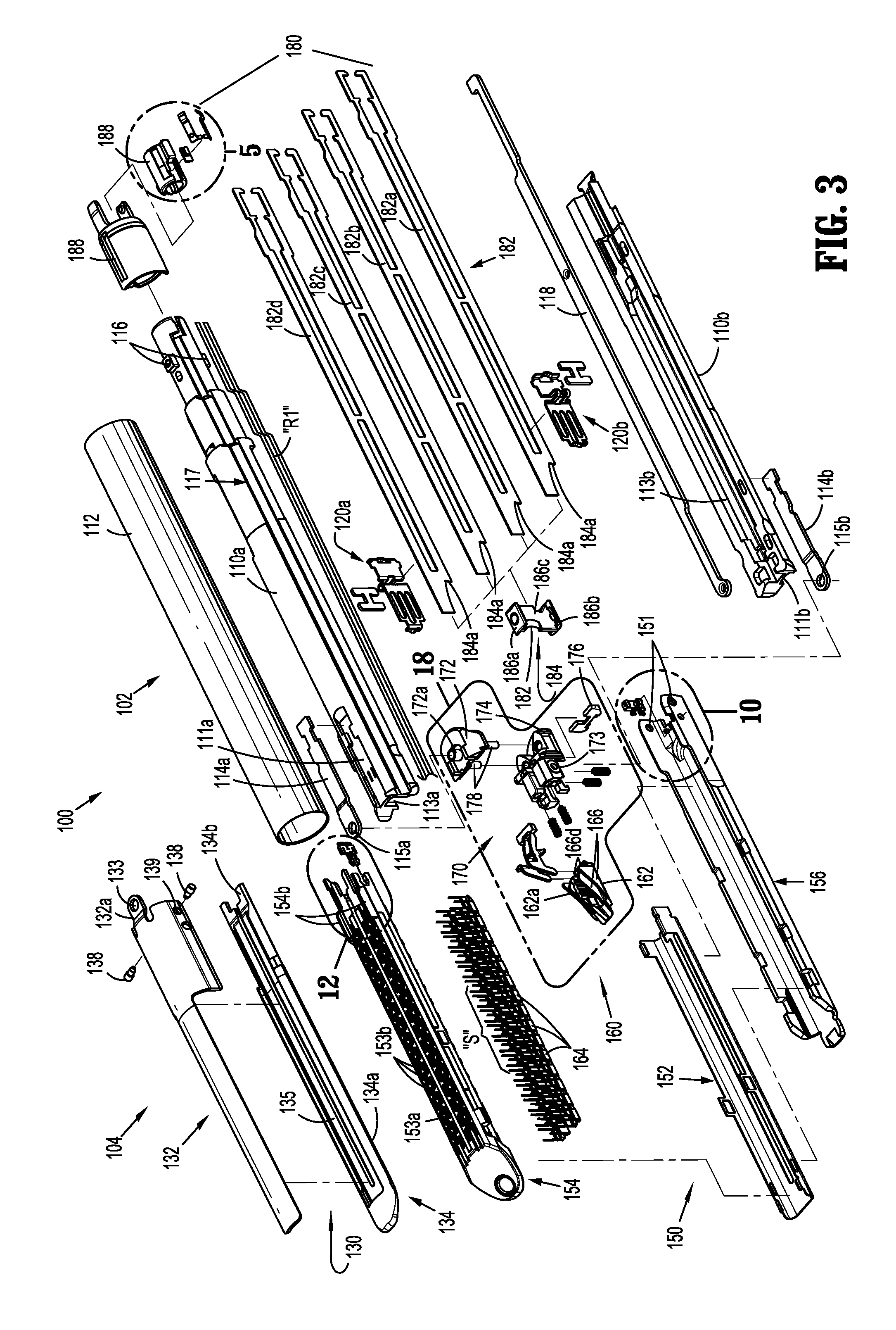
1. A surgical stapling apparatus comprising: a tool assembly including: a chip assembly including a housing and a programmable chip secured to the housing, the housing having a first projection a second projection, and a third projection; a staple cartridge body defining a recess and supporting the chip assembly and a plurality of staples; a support plate secured to the staple cartridge body; and a jaw member configured to releasably receive the staple cartridge body and the support plate, the jaw member including a connector assembly and a laterally extending rail, the first projection facilitating alignment and connection with the connector assembly of the jaw member, the second projection received in the recess in the staple cartridge body, and the third projection interfacing with the rail to prevent vertical movement of at least one of the chip assembly or the staple cartridge body, the connector assembly and the chip assembly having an electrical connection therebetween.
2. The surgical stapling apparatus according to claim 1, wherein the staple cartridge body, the support plate, and the chip assembly form a removable and replaceable unit.
3. The surgical stapling apparatus according to claim 1, wherein the surgical stapling apparatus is a loading unit having a body portion including a connection assembly supported on a proximal end thereof.
4. The surgical stapling apparatus according to claim 3, wherein the connection assembly forms an electrical connection with an adapter assembly.
5. The surgical stapling apparatus according to claim 1, wherein a portion of the staple cartridge body extends proximally and is configured to be disposed underneath the rail.
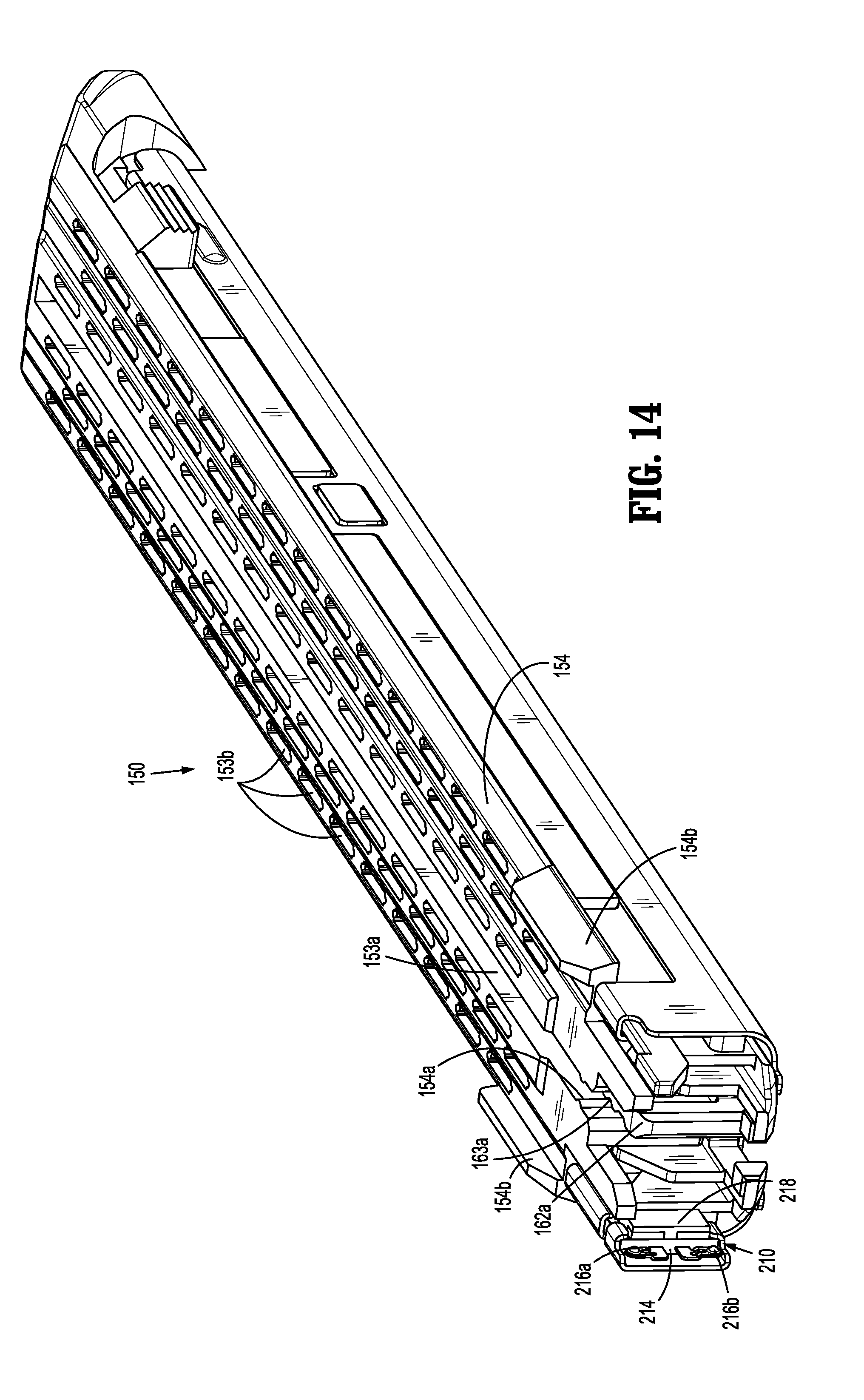
6. The surgical stapling apparatus according to claim 1, wherein the support plate includes a tab and the second projection defines a notch for receiving the tab.
7. The surgical stapling apparatus according to claim 1, wherein the staple cartridge body has at least one tab extending from the side of the staple cartridge body.
8. The surgical stapling apparatus according to claim 7, wherein the at least one tab has a length, the length of the at least one tab being indicative of a length of a staple line defined by the staple cartridge body.
9. A tool assembly comprising: a jaw member including a connector assembly; a staple cartridge body releasably received in the jaw member, the staple cartridge body supporting a plurality of staples and defining a recess; a support plate secured to the staple cartridge body, the support plate having a tab; and a chip assembly including a housing and a programmable chip secured to the housing, the housing having a first projection and a second projection, the first projection facilitating alignment and connection with the connector assembly and the second projection received in the recess in the staple cartridge body, the second projection defining a notch for receiving the tab of the support plate, wherein the connector assembly and the chip assembly include an electrical connection therebetween.
10. The tool assembly according to claim 9, wherein the staple cartridge body and the chip assembly are removable from the jaw member.
11. The tool assembly according to claim 9, further including a body portion having a proximal end and a connection assembly supported on the proximal end.
12. The tool assembly according to claim 11, wherein the connection assembly is configured to form an electrical connection with an adapter assembly.
13. The tool assembly according to claim 9, wherein the jaw includes a laterally extending rail.
14. The tool assembly according to claim 13, wherein the chip assembly includes a third projection that interfaces with the rail to prevent vertical movement of at least one of the chip assembly or the staple cartridge body.
15. The tool assembly according to claim 13, wherein a portion of the staple cartridge body includes a proximally extending portion that is disposed underneath the rail.
16. The tool assembly according to claim 9, wherein the staple cartridge body includes a side and at least one tab extending from the side.
17. The tool assembly according to claim 16, wherein the at least one tab includes a length, the length of the at least one tab being indicative of a length of a staple line defined by the staple cartridge body.
Description
BACKGROUND
Technical Field
The present disclosure relates to surgical apparatus having an articulating tool assembly. More particularly, the present disclosure relates to a surgical apparatus including an improved cartridge and tool assemblies.
Background of Related Art
Surgical apparatus for operating on tissue are well known in the art and typically include a powered handle assembly, a body portion extending distally from the handle assembly, and a tool assembly supported on the distal end of the body portion and being articulable relative to the body portion. The tool assembly includes first and second jaws which are movable in relation to each other between unapproximated and approximated positions. In surgical stapling apparatus, the first jaw supports an anvil assembly and the second jaw supports a cartridge assembly. The cartridge assembly may be replaceable to permit reuse of the tool assembly during a surgical procedure. The replaceable cartridge assembly may be provided in a variety of configurations for use on tissue having different properties, i.e., thickness, density. For example, the different cartridge assemblies may have staples of different sizes and/or the staples may be arranged in different configurations.
Many cartridge assemblies include an identification chip that is electrically coupled to the handle assembly by a conductor extending through the body portion of the surgical stapling apparatus to ensure the handle assembly is programmed to operate with the attached cartridge assembly. During attachment of the cartridge assembly to the surgical stapling apparatus improper loading of the cartridge assembly may result into damage to the electrical connection between the cartridge assembly and the surgical stapling apparatus. To prevent damage to the electrical connections during loading of the cartridge assembly and during use of the surgical stapling apparatus, it would be beneficial to provide a cartridge assembly with an improved electrical connection.
SUMMARY
Accordingly, a surgical apparatus including an electrical conductor with a strain relief is provided. The surgical apparatus includes a body portion having a proximal end and a distal end and includes a connection assembly supported on the proximal end. The surgical apparatus further includes a tool assembly supported on a distal end of the body portion and being articulable relative to the body portion, the tool assembly including an identification assembly. In addition, the surgical apparatus includes an electrical conductor extending from the connection assembly to the identification assembly. The electrical conductor includes a strain relief portion for accommodating the articulation of the tool assembly relative to the body portion.
In embodiments, the strain relief portion includes a plurality of coils. A height of the plurality of coils may decrease from a proximal portion of the plurality of coils to a distal portion of the plurality of coils. Alternatively, the height of the plurality of coils is uniform from a proximal portion of the plurality of coils to a distal portion. The plurality of coils may be equally spaced relative to each other.
In some embodiments, the body portion defines a channel for receiving the electrical conductor. The channel may include a central portion for receiving the strain relief portion of the electrical conductor. The surgical apparatus may include a powered handle assembly and the electrical conductor electrically couples the identification assembly to the handle assembly. The tool assembly may include a stapling assembly. The stapling assembly may include a removable cartridge assembly. The electrical conductor may include a flexible cable. The flexible cable may include a proximal portion and a distal portion. The proximal portion of the flexible cable may be axially affixed to the body portion, for example, using adhesive.
In embodiments, the strain relief portion is configured to permit lengthening of the electrical conductor. Alternatively, or in addition, the strain relief portion is configured to permit shortening of the electrical conductor. The body portion, the tool assembly, and the electrical conductor may form a loading unit which is configured to be releasably coupled to a powered handle assembly.
The loading unit may include a jaw member and a cartridge assembly selectively receivable within the jaw member. The identification assembly may include a connector assembly disposed within the jaw member and a chip assembly disposed within the cartridge assembly. Loading of the cartridge assembly within the jaw member may cause engagement of the chip assembly with the connector assembly. The electrical conductor may include a connector member integrally formed on a proximal end thereof. The electrical conductor may include a stiffened portion attached to the electrical conductor.
In a further aspect, a surgical stapling apparatus comprises a tool assembly having a chip assembly, a staple cartridge body, a support plate, and a jaw member, the chip assembly having a first projection facilitating alignment with and connection with a connector assembly of the jaw member, the chip assembly having a second projection received in a recess in the staple cartridge body, and the connector assembly and chip assembly having an electrical connection therebetween.
The staple cartridge body, support plate, and chip assembly may form a removable and replaceable unit. The apparatus can be a loading unit having a body portion including a connection assembly supported on a proximal end thereof. The connection assembly can form an electrical connection with an adapter assembly.
The jaw can include a rail extending laterally. The chip assembly can have a third projection that interfaces with the rail to prevent vertical movement of the chip assembly, the staple cartridge body, or both. A portion of the staple cartridge body can extend proximally and can be configured to be disposed underneath the rail.
The second projection can define a notch for receiving a tab on the support plate. The staple cartridge body has at least one tab extending from the side of the staple cartridge body. The staple cartridge body at least one tab can have a length; the length of the at least one tab can be indicative of a length of a staple line defined by the staple cartridge body.
In a further aspect, a removable and replaceable staple cartridge assembly has a shipping wedge overlying a tissue contacting surface of the staple cartridge assembly, the shipping wedge includes a cartridge release projection. The staple cartridge body can define a recess that would be disposed adjacent a distal end of the stapler jaw when the shipping wedge is attached to the staple cartridge assembly. Insertion of the projection into the recess can be used to release the staple cartridge body from the stapler jaw.
The shipping wedge may have a raised portion on a proximal end thereof to prevent approximation of a stapler anvil with the staple cartridge assembly, after the staple cartridge assembly has been inserted into the stapler.
BRIEF DESCRIPTION OF THE DRAWINGS
Various embodiments of the present disclosure are described herein with reference to the drawings, wherein:
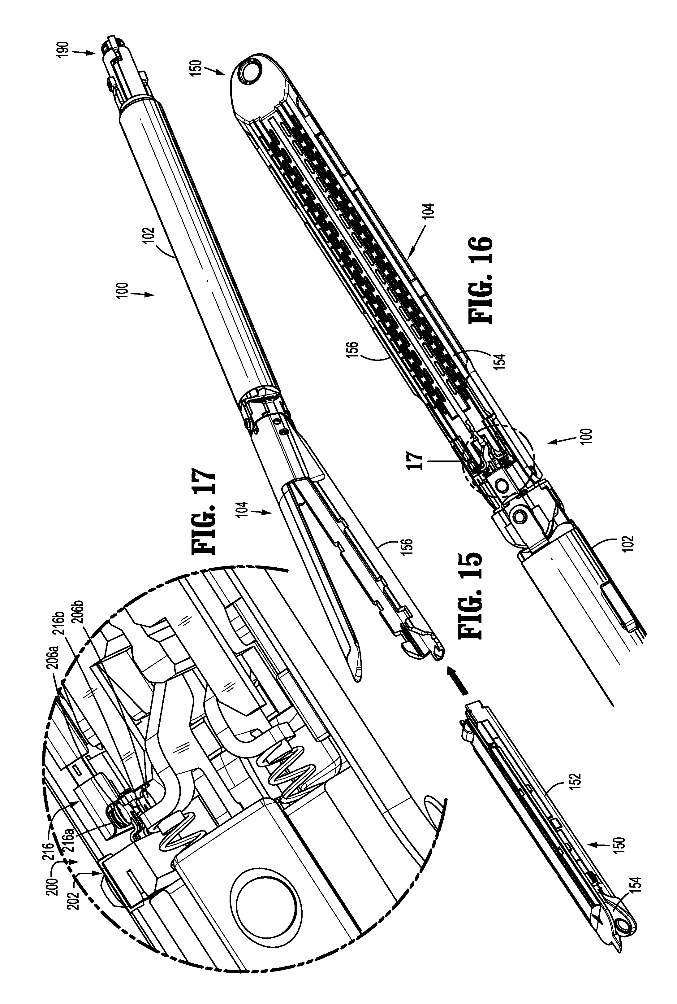
FIG. 1 is a side, perspective view of an embodiment of the presently disclosed surgical stapling apparatus including a tool assembly in an approximated position;
FIG. 2 is a side, perspective view of a disposable loading unit of the surgical stapling apparatus shown in FIG. 1;
FIG. 3 is a side, perspective view of the loading unit shown in FIG. 2 with parts separated;
FIG. 4 is an enlarged side, perspective bottom view of a mounting assembly and a firing lockout assembly of the loading unit shown in FIG. 2 with parts separated;
FIG. 5 is a side perspective view of the indicated area of detail shown in FIG. 2;
FIG. 6 is an enlarged perspective view of a proximal end of the loading unit shown in FIG. 2;
FIG. 7 is a side, perspective view of the proximal end of the loading unit shown in FIG. 2 with an upper housing half removed;
FIG. 7 is a side, perspective view of a latch member of the lockout mechanism supported on the mounting assembly adjacent a working end of the drive member;
FIG. 8 is a side, perspective view of an identification assembly of the loading unit shown in FIG. 2 with parts separated;
FIG. 9 is a side, perspective view of the identification assembly shown in FIG. 8;
FIG. 10 is a perspective view of a connector assembly of the identification assembly shown in FIG. 8 and a proximal end of a jaw member of the loading unit shown in FIG. 2 with parts separated;
FIG. 11 is an alternative perspective view of the connector assembly and jaw member shown in FIG. 10;
FIG. 12 is an enlarged view of the indicated area of detail shown in FIG. 3;
FIG. 13 is a side, perspective view of a chip assembly of the identification assembly shown in FIG. 8 secured to a cartridge body of the loading unit shown in FIG. 2;
FIG. 14 is a perspective end view of a cartridge assembly of the loading unit shown in FIG. 2 including the chip assembly shown in FIG. 13;
FIG. 15 is a side, perspective view of the cartridge assembly shown in FIG. 14 being loaded into the loading unit shown in FIG. 2;
FIG. 16 is a top perspective view of the loading unit shown in FIG. 2 with an anvil assembly removed;
FIG. 17 is an enlarged view of the indicated area of detail shown in FIG. 16;
FIG. 18 is a perspective view of the mounting assembly and firing lockout assembly shown in FIG. 4 with parts separated;
FIG. 19 is an enlarged perspective view of a latch member of the firing lockout assembly shown in FIG. 18;
FIG. 20 is a bottom, perspective view of the firing lockout assembly and the mounting assembly shown in FIG. 18 and distal end of a drive assembly of the loading unit shown in FIG. 2;
FIG. 21 is a side, cross-sectional view of the distal end of the drive assembly shown in FIG. 20 and the latch member shown in FIG. 19 in a first or unlocked configuration;
FIG. 22 is a cross-sectional side view of the distal end of the drive assembly and the latch member shown in FIG. 21 in a second or locked configuration;
FIG. 23 is a cross-sectional side view taken along line 23-23 shown in FIG. 2;
FIG. 24 is an enlarged view of the indicated area of detail shown in FIG. 23;
FIG. 25 is a side, perspective view of the firing lockout assembly shown in FIG. 18;
FIG. 26 is a side, cross-sectional view taken along line 26-26 shown in FIG. 25;
FIG. 27 is a top view of a tool assembly of the loading unit shown in FIG. 2 with the anvil plate removed;
FIG. 28 is an enlarged view of a proximal end of the tool assembly shown in FIG. 27 in a first articulated position;
FIG. 29 is a side, perspective view of a cartridge assembly of the loading unit shown in FIG. 2 and a shipping wedge according to an embodiment of the present disclosure;
FIG. 30 is a bottom, perspective view of the shipping wedge shown in FIG. 29;
FIG. 31 is a side, perspective view of a loading unit according to another embodiment of the present disclosure, including a flexible cable;
FIG. 32 is a schematic view of the flexible cable of the loading unit shown in FIG. 31;
FIG. 33 is a side, perspective view of a disposable loading unit according to another embodiment of the present disclosure;
FIG. 34 is a side, perspective view of the loading unit shown in FIG. 33 with parts separated;
FIG. 35 is a side perspective view of the indicated area of detail shown in FIG. 34 showing a mounting assembly and a firing lockout assembly;
FIG. 36 is a perspective bottom view of the mounting assembly and the firing lockout assembly shown in FIG. 35 with parts separated;
FIG. 37 is a side, perspective view of the firing lockout assembly shown in FIG. 35;
FIG. 38 is a side, cross-sectional view taken along line 38-38 shown in FIG. 37;
FIG. 39 is a side perspective view of the indicated area of detail shown in FIG. 34;
FIG. 40 is an enlarged perspective view of a proximal end of the loading unit shown in FIG. 33;
FIG. 41 is a side, perspective view of the proximal end of the loading unit shown in FIG. 40 with an upper housing half removed;
FIG. 42 is a side, perspective view of an identification assembly of the loading unit shown in FIG. 33 with parts separated;
FIG. 43 is a side, perspective view of the identification assembly shown in FIG. 42;
FIG. 44 is a perspective view of a connector assembly of the identification assembly shown in FIG. 42 and a proximal end of a jaw member of the loading unit shown in FIG. 33 with parts separated;
FIG. 45 is an alternative perspective view of the connector assembly and jaw member shown in FIG. 44;
FIG. 46 is an enlarged view of the indicated area of detail shown in FIG. 34;
FIG. 47 is a side, perspective view of a chip assembly of the identification assembly shown in FIG. 42 secured to a cartridge body of the loading unit shown in FIG. 33 and received within a support plate of the loading unit;
FIG. 48 is a cross-sectional end view taken along line 48-48 shown in FIG. 47;
FIG. 49 is a cross-sectional end view taken along line 49-49 shown in FIG. 47;
FIG. 50 is a perspective end view of a cartridge assembly of the loading unit shown in FIG. 33 including the chip assembly shown in FIG. 47;
FIG. 51 is an enlarged view of the indicated area of detail shown in FIG. 50;
FIG. 52 is a perspective view of a flexible cable of the loading unit shown in FIG. 33;
FIG. 53 is a perspective view of a proximal end of a flexible cable according to an alternative embodiment of the present disclosure;
FIG. 54 is a perspective view of a distal end of the flexible cable shown in FIG. 53;
FIG. 55 is a perspective side view of the mounting assembly shown in FIG. 35;
FIG. 56 is a perspective side view of a proximal end of the tool assembly of the loading unit shown in FIG. 33, with an anvil assembly removed;
FIG. 57 is a perspective side view of the proximal end of the tool assembly of the loading unit shown in FIG. 33 during loading of a cartridge assembly;
FIG. 58 is a perspective view of a cartridge body of a cartridge assembly having a first length and a jaw member of a second length;
FIG. 59 is a perspective view of a cartridge body of a cartridge assembly having a the second length and a jaw member of the first length.
FIG. 60 is a side, perspective view of a cartridge assembly of the loading unit shown in FIG. 33 and a shipping wedge according to another embodiment of the present disclosure;
FIG. 61 is a bottom, perspective view of the shipping wedge shown in FIG. 29.
DETAILED DESCRIPTION OF THE DRAWINGS
Embodiments of the presently disclosed surgical apparatus will now be described in detail with reference to the drawings wherein like reference numerals designate identical or corresponding elements in each of the several views. In this description, the term "proximal" is generally used to refer to the portion of the apparatus that is closer to a clinician, while the term "distal" is generally used to refer to the portion of the apparatus that is farther from the clinician.
As a tool assembly of a surgical apparatus is articulated, any cables extending from the body portion to the tool assembly experience strain, i.e., compression or tension. During articulation of the tool assembly, the strain experienced by the cable or cables may damage the cables or cause the cables to become detached. The embodiments of the present disclosure address providing a strain relief for relieving the strain experienced by the cable or cables during articulation of the tool assembly. The embodiments of the present disclosure further address preventing damage to the electrical connections within the tool assembly and the surgical apparatus.
FIG. 1 illustrates an embodiment of the presently disclosed surgical apparatus shown generally as surgical stapler 10. Although illustrated as a surgical stapler, the apparatus may include other types of end effectors including forceps, retractors, clip appliers or the like. The surgical stapler 10 includes a powered handle assembly 12, a body portion 14, and a loading unit 100. Handle assembly 12 and body portion 14 are configured to effect operation of loading unit 100. For a detailed description of the structure and function of handle assembly 12 and body portion 14, please refer to commonly owned U.S. Patent Application Publication No. 2012/0253329 ("the '329 publication"), the content of which is incorporated by reference herein in its entirety. Although loading unit 100 is shown and described as being selectively secured to body portion 14 of surgical stapler 10, it is envisioned that loading unit 100 can be supported directly on the distal end of the body portion 14.
Referring to FIGS. 1 and 2, the loading unit 100 includes a proximal body portion 102 and a tool assembly 104. A mounting assembly 170 is secured to the tool assembly 104 and is pivotally coupled to the proximal body portion 102 of the loading unit 100 to pivotally secure the tool assembly 104 to the proximal body portion 102. The loading unit 100 is substantially as described in U.S. Patent Application Publication No. 2013/0098965 ("the '965 publication") except that the firing lockout mechanism has been changed, and components for cooperating with a powered handle assembly, i.e., an identification assembly and a flexible cable, and a shipping wedge have been added. The '965 publication is hereby incorporated by reference herein in its entirety. Accordingly, the components of the loading unit 100 which are common to those which are disclosed in the '965 publication, will only be briefly described herein. In contrast, the components which are newly presented herein, including a connection assembly 190 (FIGS. 5-7), an identification assembly 200 (FIGS. 8-17), a firing lockout assembly 220 (FIGS. 19-28), a shipping wedge 300 (FIGS. 29 and 30), a flexible cable "R2" (FIGS. 31 and 32) and their methods of operation will be described in detail herein.
With reference to FIG. 3, the proximal body portion 102 of the loading unit 100 includes an upper housing half 110a and a lower housing half 110b which are contained within an outer sleeve 112. The upper housing half 110a defines a recess 111a for receiving a first end of a first coupling member 114a and the lower housing half 110b defines a recess 111b for receiving a first end of a second coupling member 114b. When the outer sleeve 112 is positioned about the upper and lower housing halves 110a, 110b, the first and second coupling members 114a and 114b are retained within the respective recesses 111a, 111b by the outer sleeve 112.
The proximal end of the upper housing half 110a includes engagement nubs 116 for releasably engaging the distal end of the body portion 14 (FIG. 1) of the stapling apparatus 10 (FIG. 1) in a bayonet-type coupling arrangement. The upper and lower housing halves 110a, 110b each define a channel 113a, 113b, respectively, for slidably receiving a drive member 182 of a drive assembly 180, as will be described in further detail below. An articulation link 118 is slidably positioned between the upper and lower housing halves 110a, 110b and is adapted to engage an articulation mechanism (not shown) of the surgical stapler 10 (FIG. 1) to facilitate articulation of the tool assembly 104 in relation to the proximal body portion 102. A pair of blow out plate assemblies 120a, 120b are positioned adjacent the distal end of the upper and lower housing halves 110a, 110b to prevent outward buckling and/or bulging of the drive member 182 during articulation and firing of the tool assembly 104.
A channel 117 extends the length of upper housing half 110a for receiving a conductor, e.g., electrical ribbon or cable "R1" or wires. As will be described in further detail below, electrical ribbon "R1" electrically couples a connection assembly 190 disposed in a proximal end of the proximal body portion 102 of the loading unit 100 with an identification assembly 200 (FIG. 8) disposed within the tool assembly 104 of the loading unit 100. A more detailed description of the components of the proximal body portion 102 is provided in commonly owned U.S. Pat. No. 7,143,924 ("the '924 patent") the content of which is hereby incorporated by reference herein in its entirety.
Still referring to FIG. 3, the tool assembly 104 includes an anvil assembly 130 and a replaceable cartridge assembly 150 which are movable in relation to each other between unapproximated and approximated positions. The anvil assembly 130 includes an anvil body 132 and an anvil plate 134 which is secured to the underside of the anvil body 132 to define a channel 131 (FIG. 24). A proximal end of the anvil body 132 includes a bracket 132a defining a hole 133 for receiving a cylindrical pivot member 172a of an upper mounting portion 172 of a mounting assembly 170. The anvil plate 134 defines a longitudinal slot 135 which is dimensioned to slidably receive a portion of the working end 184 of a drive member 182 as will be discussed in further detail below. A tissue contacting surface 134a of the anvil plate 134 defines a plurality of staple receiving depressions (not shown).
The cartridge assembly 150 includes a support plate 152, cartridge body 154, a plurality of staples "S", and a staple firing assembly 160 that includes an actuation sled 162 and is further described below. The cartridge assembly 150 is receivable in a jaw member 156. The cartridge body 154 and the support plate 152 are attached to the jaw member 156 by a snap-fit connection as described in the '965 publication which has been incorporated herein by reference. Other forms of connection are contemplated and can be used in place of the snap-fit connection or in addition thereto.
The jaw member 156 is pivotally secured to the anvil body 132 by pivot pins 138 which extend through openings 139 formed in the anvil body 132 and openings 151 formed in the jaw member 156. The cartridge body 154 defines a longitudinal slot 153a and a plurality of laterally spaced staple retention slots 153b which are positioned in alignment with the staple receiving depressions (not shown) in the tissue contacting surface 134a of the anvil plate 134. An actuation sled 162 is configured to translate through the cartridge body 154. The longitudinal slot 153a of the cartridge body 154 receives a projection 162a formed on the actuation sled 162 to guide the actuation sled 162 through the cartridge body 154. The cartridge body 154 includes a detent 154a (FIG. 14) extending within the longitudinal slot 153a which are received in the recesses 163a (FIG. 14) formed on the projection 162a of the actuation sled 162 to secure the actuation sled 162 in place during shipping of the cartridge assembly 150. Each retention slot 153b receives a fastener or staple "S" and a pusher 164. The actuation sled 162 is positioned within the cartridge body 154 to pass longitudinally through the cartridge body 154 into engagement with the pushers 164 to sequentially eject the staples "S" from the cartridge body 154. The cartridge body 154 further includes a pair of tissue stop members 154b (FIG. 14) which prevent tissue (not shown) from being positioned proximally of the staple retention slots 153b. For a more detailed discussion of the cartridge assembly 150 including the support plate 152, see the '965 publication which has been incorporated herein by reference.
Referring to FIGS. 3 and 4, the mounting assembly 170 includes the upper and lower mounting portions 172, 174 and a retention blade 176. As shown, the upper and lower mounting portions 172, 174 are secured together by the posts 178 that extend from the upper mounting portion 172. Each of the upper and lower mounting portions 172, 174 includes a pivot member 172a (FIG. 3) and 174a (FIG. 4), respectively. As described above, the pivot member 172a on the upper mounting portion 172 is received within the hole 133 (FIG. 3) of the bracket 132a of the anvil body 132 to secure the upper mounting portion 172 to the anvil body 132. The first coupling member 114a (FIG. 3) of the proximal body portion 102 has a second end which defines an opening 115a which also receives the pivot member 172a. The pivot member 174a on the lower mounting portion 174 is received in an opening 115b of the second coupling member 114b (FIG. 3) of the proximal body portion 102. The pivot pins 138 which secure the anvil body 132 to the jaw member 156 extend through the openings 139 formed in the anvil body 132 and the openings 151 formed in the jaw member 156 and are received in the openings 173 formed in the lower mounting portion 174 to secure the lower mounting portion 174 to the jaw member 156 (FIG. 3). The lower mounting portion 174 defines a slot 177 for receiving the retention blade 176. As will be described in further detail below, retention blade 176 includes a curved distal facing surface 176a (FIG. 4) and a pair of limiting members 176b (FIG. 4).
The drive assembly 180 includes the drive member 182 having a body and a working end 184. The working end 184 includes an upper flange 186a, a lower flange 186b, a vertical strut 186c interconnecting the upper flange 186a and the lower flange 186b, and a knife 187 supported on or formed into the vertical strut 186c. The upper flange 186a is positioned to be slidably received within the channel 131 (FIG. 24) of the anvil assembly 130 and the lower flange 186b is positioned to be slidably positioned along an outer surface 156a (FIG. 24) of the jaw member 156. In use, distal movement of the drive member 182 initially advances the upper flange 186a into a cam surface 134b formed on the anvil plate 134 and advances the lower flange 186b into engagement with a cam surface 156b formed on the jaw member 156 to pivot the cartridge assembly 150 towards the anvil assembly 130 to the approximated or closed position. Continued advancement of the drive member 182 progressively maintains a minimum tissue gap between the anvil assembly 130 and the cartridge assembly 150 adjacent the working end 184 of the drive assembly 180 as the working end 184 moves through the tool assembly 104.
The distal end of the body of the drive member 182 supports the working end 184 of the drive member 182 and defines a stop surface 184a. The actuation sled 162 (FIG. 3) is disposed within the cartridge assembly 150 (FIG. 3) at a position distal of the working end 184. When the working end 184 is in its proximal-most position and the tool assembly 104 is in the open or unapproximated position (FIG. 24), the sled 162 and the working end 184 are in their initial position. The sled 162 includes a plurality of cam surfaces 166a which are positioned to engage and lift the pushers 164 within the staple retention slots 153b of the cartridge body 154. The pushers 164 (FIG. 3) are positioned within the cartridge assembly 150 to eject the staples "S" from the cartridge body 154 when the sled 162 is advanced through the tool assembly 104. The proximal end of the sled 162 includes one or more fingers 166a which define an opening or slot 163 (FIG. 4) which will be described in further detail below.
In certain embodiments, the body of the drive member 182 is formed from a plurality of stacked sheets 182a-d of material, e.g., stainless steel. A locking member 188 (FIG. 3) is supported about the proximal end of the loading unit 100 to prevent axial movement of the drive member 182 until the loading unit 100 is attached to the stapling apparatus 10 (FIG. 1). A more detailed discussion of the above-identified components of the loading unit 100 is described in the '924 patent which has been incorporated herein by reference in its entirety.
With reference to FIGS. 5-7, a connection assembly 190 is supported on a proximal end of the upper housing half 110a of the proximal body portion 102 of the loading unit 100 and provides an electrical connection between the loading unit 100 and the surgical stapler 10 (FIG. 1). The connection assembly 190 includes a connector housing 192, a contact member 194, and an electronic chip 196. The contact member 194 includes a pair of contact portions 194a that are received within the recesses 193 of the connector 192. The contact portions 194a are positioned to engage corresponding contact portions (not shown) of a contact member (not shown) disposed within the elongate body 14 (FIG. 1) of the surgical stapler 10 (FIG. 1). The contact member 194 includes a connector portion 194b that extends between the contact portions 194a. As described above, a conductor, e.g., electrical ribbon or cable "R1" or wires, extends through the proximal body portion 102 of the loading unit 100 and into the tool assembly 104 to electrically couple the connection assembly 190 with the identification assembly 200 (FIG. 8).
During attachment of the loading unit 100 to the elongate body 14 (FIG. 1) of the surgical stapler 10 (FIG. 1), the contact portions 194a of the contact member 194 of connection assembly 190 are positioned to engage the contact portions (not shown) of a connector assembly (not shown) supported within a distal end of the elongate body 14 (FIG. 1) of the surgical stapler 10 (FIG. 1). Engagement of the contact members 194a of the connection assembly 190 with the contact members of the connector assembly of the surgical stapler 10 connects the identification assembly 200 (FIG. 8) of the loading unit 100 with the handle assembly 12 (FIG. 1) of the surgical stapler 10 (FIG. 1). As noted above, the loading unit 100 may be attached to the elongate body 14 with a bayonet coupling or in any other suitable manner.
With reference now to FIGS. 8-17, the identification assembly 200 of the loading unit 100 includes a connector assembly 202 and a chip assembly 212. The connector assembly 202 includes a connector housing 204. A tab 206a and a protrusion 206b extend outwardly from connector housing 204. The tab 206a is received within an opening 157a (FIG. 10) in the jaw member 156 of the tool assembly 104 to align the connector housing 204 with the jaw member 156 and the protrusion 206b is received within an opening 157b (FIG. 10) in the jaw member 156 to secure the connector assembly 202 to the jaw member 156. The connector housing 204 receives a distal end of the conductor, e.g., electrical ribbon "R1" (FIG. 11), that extends from the connection assembly 190 (FIG. 6) to electrically communicate the contact member 194 of the connection assembly 190 (FIG. 7) with the first and second contact members 206a, 206b. In embodiments, electrical ribbon "R1" is soldered to the first and second contact members 206a, 206b and the connector housing 204 is molded about the distal end of the electrical ribbon "R1" and the first and second contact members 206a, 206b to secure the electrical ribbon "R1" with the first and second contact members 206a, 206b. The contact members 206a, 206b extend distally from the connector housing 204 when the connector housing 204 is secured to the jaw member 156.
The chip assembly 212 includes a chip housing 214 and an identification chip 218. A projection 214a extends from the chip housing 214 and is received within a recess 155 (FIG. 12) formed in a proximal end of the cartridge body 154 (FIG. 12) of the cartridge assembly 150 to secure the chip assembly 212 to the cartridge body 154. The chip assembly 212 further includes first and second contact members 216a, 216b that extend from the chip housing 214 and communicate with the identification chip 218.
The first and second contact members 216a, 216b engage the respective first and second contact members 206a, 206b of the connector assembly 202 when the cartridge body 154 is received within the jaw member 156 (FIG. 16). In embodiments, and as shown, the first and second contact members 206a, 206b of the connector assembly 202 and first and second contact members 216a, 216b of the chip assembly 212 are supported on the connector housing 204 and the chip housing 214, respectively, in a cantilevered fashion to permit engagement between the first contact members 206a, 216a and between the second contact members 206b, 216b. The first and second contact members 206a, 206b of the connector assembly 202 and the first and second contact members 216a, 216b of the chip assembly 212 may include a substantially spherical shape to facilitate engagement between the connector assembly 202 and the chip assembly 212.
The identification chip 218 may include any commercially available chip capable of storing information including specifications of the cartridge assembly 150, e.g., cartridge size, staple arrangement, staple length, clamp-up distance, production date, model number, lot number, expiration date, etc., and transmitting at least some of the information to the handle assembly 12 (FIG. 1). In one embodiment, the identification chip 218 includes an erasable programmable read only memory ("EPROM") chip. In this manner, the configuration of an attached cartridge assembly 150 may be relayed to the handle assembly 12 such that, for example, the firing forces and/or the length of the firing stroke of the handle assembly 12 may be adjusted to accommodate the particular cartridge assembly 150. It is envisioned that instead of an EPROM, the identification chip 218 may be a read/write memory chip, such as read/write RAM, such that data may be written onto the identification chip 218. For example, usage information may be written onto the identification chip 218 that identifies that the loading unit 100 has been fully or partially fired to prevent reuse of an empty or partially fired loading unit, or for any other purpose.
With particular reference to FIGS. 16-18, as the cartridge assembly 150 is received within the jaw member 156 of the loading unit, the first and second contact members 216a, 216b of the chip assembly 212 engage the first and second contact member 206a, 206b of the connector assembly 202. Once the first and second contact members 216a, 216b of the chip assembly 212 are engaged with the respective first and second contact members 206a, 206b of the connector assembly 202, information stored on the identification chip 218 of the chip assembly 212 may be relayed to the handle assembly 12 upon connection of the loading unit 100 to the body portion 14 of the surgical stapler 10. As described above, the identification assembly 200 is connected to the surgical stapler 10 (FIG. 1) via a conductor, e.g., electrical ribbon or cable "R1" (FIGS. 7 and 11), extending through the loading unit 100 and by the connection assembly 190 (FIG. 6) which is disposed within a proximal end of the loading unit 100.
The firing lockout assembly 220 will now be described with reference to FIGS. 18-28. The firing lockout assembly 220 is substantially similar to the firing lockout assembly described in U.S. patent application Ser. No. 14/230,516 ("the '516 application"), filed Mar. 31, 2014, and will only be described in detail with reference to the differences therebetween. Accordingly, the content of the '516 application is incorporated by reference herein in its entirety.
The firing lockout assembly 220 includes a latch member 222 which is pivotally supported on a distal end of the lower mounting portion 174. The latch member 222 includes a U-shaped body (FIG. 19) having a proximal base member 224 and two spaced distally extending legs 226. As shown, the base member 224 is provided with a blocking member 224a which defines a blocking surface and is welded or secured to the base member 224 to provide additional support to the base member 224. Alternatively, the base member 224 and the blocking member 224a are integrally or monolithically formed. The latch member 222 is pivotal from a first position (FIG. 21) to a second position (FIG. 22). In the first position shown in FIG. 21, the blocking member 224a of the latch member 222 is aligned with the stop surface 184a of the drive member 182 to prevent advancement of the drive member 182 within the tool assembly 104. In the second position shown in FIG. 22, the blocking member 224a is misaligned with the stop surface 184a of the drive member 182 to permit advancement of the drive member 182 within the tool assembly 104.
With particular reference to FIGS. 18-20, each of the legs 226 of the latch member 222 has a centrally located pivot member 228 and an abutment surface 230. The pivot members 228 are supported on hooked arms 174b (FIG. 20) of the lower mounting portion 174 of the mounting assembly 170 to pivotally support the latch member 222 on the lower mounting portion 174. A biasing member includes a pair of springs 232 (FIG. 18) which is supported within respective bores 175a (FIG. 18) formed in a distal face of the lower mounting portion 174 to urge the latch member 222 towards the first position. Each of the springs 232 is positioned to engage a nub 230a formed on the respective abutment surfaces 230 of the latch member 222 to bias the latch member 222 in a counter-clockwise direction as viewed in FIG. 24. A distal end of each of the legs 226 includes a downwardly extending projection 234 which is positioned to extend through an opening 163 (FIG. 20) defined in the sled 162 when the sled 162 is in a retracted position, the latch member 222 is in the first position, and the anvil assembly 130 and the cartridge assembly 150 are in an approximated position.
A pair of springs 236 is positioned between the inner surface 156b (FIG. 10) of the jaw member 156 and a respective bore 175b (FIG. 20) defined in a bottom surface of the lower mounting portion 174 to urge the tool assembly 104 to the unapproximated position (FIG. 2). Jaw member 156 includes a pair of cylinders 158 (FIGS. 10 and 11) for engaging springs 236.
Referring to FIGS. 23 and 24, when the drive member 182 is in the fully retracted position and the tool assembly 104 is in the unapproximated or open position, the upper and lower flanges 186a, 186b of the working end 184 of the drive member 182 are spaced proximally of the sled 162 and proximally of cam surfaces 238a, 238b formed on the anvil plate 134 and the jaw member 156, respectively. In the unapproximated position of the tool assembly 104, the latch member 222 is urged towards a counter-clockwise position by springs 232. The lower mounting portion 174 includes a surface 240 which is positioned to engage the base member 224 or blocking member 224a. Engagement between the blocking member 224a and the surface 240 of the lower mounting portion 174 prevents further counter-clockwise rotation of the latch member 222 to retain the latch member 222 in the first position. As shown in FIG. 25, the blocking member 224a engages a gusset 174c of the lower mounting portion 174 to prevent distal movement of the latch member 222 when the firing lockout assembly 220 is in the locked configuration.
The operation of the firing lockout assembly 220 is described in detail in the '516 application. Briefly, during firing of the loading unit 100, the latch member 222 of the firing lockout assembly 220 is pivoted about the pivot members 174b of the lower mounting portion 174. As described above, the retention blade 176 is received within slot 177 in the lower mounting portion 174. As illustrated in FIG. 26, the curved surface 176a of the retention blade 176 accommodates the arcuate motion of the blocking member 224a of the latch member 222 to prevent proximal movement of the latch member 222 during firing of the loading unit 100. Proximal movement of the latch member 222 could cause the pivot members 228 to separate from the hooked arms 174b of the lower mounting portion 174. Separation of the latch member 222 from the lower mounting portion 174 during firing of the loading unit 100 may result in misfiring of the loading unit 100 and/or prevent the firing lockout assembly 220 from functioning properly.
Prior to firing of the loading unit 100, the tool assembly 104 may be articulated relative to the proximal body portion 102. During articulation of the tool assembly 104, limiting member 176b of retention blade 176 engages the second coupling member 114b which extends from the proximal body portion 102 of the loading unit 100 to limit the articulation of the tool assembly 104 relative to the proximal body portion 102.
With reference to FIGS. 29 and 30, the shipping wedge 300 of cartridge assembly 150 is configured to maintain staples "S" (FIG. 3) within staple retention slots 153b of cartridge body 154 and prevent actuation of tool assembly 104 of loading unit 100 prior to removal. The shipping wedge 300 includes an elongate body 302 defining an elongate recess 303 (FIG. 30) along a bottom surface of the elongate body. A flange 304 extends from within the elongated recess 303 and includes a plurality of protrusions 304 for securing the flange 304 within the elongate slot 153a (FIG. 14) of the cartridge body 154 (FIG. 29). A proximal end of the elongate body 302 includes a raised portion 306 (FIG. 29) configured to prevent approximation of the cartridge assembly 150 (FIG. 2) towards the anvil assembly 130 (FIG. 2) once the cartridge assembly 150 is loaded within the jaw member 156 (FIG. 2) of the tool assembly 104 and prior to removal of the shipping wedge 300. A distal end of the elongate body 302 includes a projection 308 which is positioned and configured to be grasped by a clinician to facilitate separation of the shipping wedge 300 from the cartridge assembly 150. A plurality of tabs 310 extend from the elongate body 302 for engaging the cartridge body 154 of the cartridge assembly 150 to releasable secure the shipping wedge 300 to the cartridge body 154 of cartridge assembly 150.
In some embodiments, the projection 308 of the shipping wedge 300 may be used to remove the cartridge assembly 150 from the jaw member 156 after use. The cartridge body 154 can define a recess (not shown) adjacent the jaw member 156 when the cartridge assembly 150 is disposed in the jaw member 156. The shipping wedge 300 is grasped by the user and the projection 308 is inserted into the recess. The shipping wedge 300 may then be manipulated (by twisting, pivoting, etc.) to pop the cartridge assembly 150 out so that it can be removed and possibly replaced.
With reference now to FIGS. 31 and 32, a loading unit according to another embodiment of the present disclosure is shown generally as loading unit 400. The loading unit 400 is substantially similar to the loading unit 100 described hereinabove and will only be described as relates it to the differences therebetween.
The loading unit 400 includes an electrical conductor, i.e., a flexible cable or electrical ribbon "R2", for electrical coupling the connection assembly 190, disposed on a proximal end of the proximal body portion 402 of the loading unit 400, with an identification assembly 200 (FIG. 8), disposed within the tool assembly 404 of the loading unit 400. The flexible cable "R2" includes a strain relief portion. The strain relief portion is an undulating portion of the cable, enabling the loading unit to articulate and still carry the cable. The strain relief portion has at least one bend and can include a plurality of coils "c". As shown, the flexible cable "R2" includes seven (7) coils "c" of decreasing height from a proximal portion of the flexible cable "R2" to a distal portion of the flexible cable "R2". It is envisioned that flexible cable "R2" may include more or less than seven (7) coils "c" and/or that the height of the coils may increase from the proximal portion to the distal portion. Alternatively, the heights of the coils "c" may be uniform or vary in a random or uniform manner. Although shown as having uniform spacing between the coils "c", it is envisioned that the spacing between the coils "c" may be different.
The strain relief portion may be biased to an initial configuration. For example, the material and shape of the cable biases the cable to the coiled configuration shown in FIGS. 31 and 32. During articulation, as described below, the undulating shape of the strain relief portion will open up. Upon returning the tool assembly to a straighter configuration, less articulated position, or non-articulated position, the undulating shape, or coiled shape will close, eventually returning to the initial configuration in the non-articulated position.
During articulation of the tool assembly 404 of the loading unit 400 relative to the proximal body portion 402 of the loading unit 400, the flexible cable "R2" experiences strain. The strain experienced by the flexible cable "R2" is a result of the distance between the connection assembly 190 proximal body portion 402 and the identification assembly 200 disposed within the tool assembly 404 changing as the tool assembly 404 articulates relative to the proximal body portion 402. In particular, the distance between the connection assembly 190 and the identification assembly 200 increases as the tool assembly 404 articulates in a first direction, as indicated by arrow "D" in FIG. 31, and the distance between the connection assembly 190 and the identification assembly 200 decreases as the tool assembly 404 articulates in a second direction, as indicated by arrow "E" in FIG. 31.
The coils "c" of the flexible cable "R2" allow the flexible cable "R2" to have a variable length by deforming in response to a strain on the flexible cable "R2". In particular, when tension is applied to a distal end of the flexible cable "R2", as indicated by arrow "A" in FIG. 32, flexion of each coil "c", as indicated by arrows "a.sub.1" in FIG. 32, and/or outward flexion of the coils "c" relative to each other, as indicated by arrows "a.sub.2" in FIG. 32, permits the flexible cable "R2" to lengthen, thereby relieving the strain on the flexible cable "R2". When compression is applied to the flexible cable "R2", as indicted by arrow "B" in FIG. 32, inward flexion of each coil "c", as indicated by arrows "b.sub.1,", and/or inward flexion of the coils "R2" relative to each other, as indicted by arrows "b.sub.2" in FIG. 32, permits the flexible cable "R2" to shorten, thereby relieving the strain on the flexible cable "R2".
The proximal body portion 402 of loading unit 400 includes an upper housing half 410a and a lower housing half 410b. A channel 417 extends a length of upper housing half 410a and receives the flexible cable "R2". The channel 417 includes proximal and distal portions 317a, 417b for receiving the proximal and distal portions of the flexible cable "R2", and a central portion 417c for receiving the coils "c" of the flexible cable "R2" and accommodating the flexion of the coils "c" when the flexible cable "R2" is experiencing strain.
The flexible cable "R2" extends the length of the proximal body portion 402 of loading unit 400 and into the tool assembly 404 of loading unit 400. The flexible cable "R2" electrically couples the connection assembly 190 disposed with the proximal body portion 302 of the loading unit 400 with the identification assembly 200 (FIG. 8) disposed within the tool assembly 404 of the loading unit 400. The flexible cable "R2" may be loosely received within the channel 417 to permit longitudinal movement of the flexible cable "R2". In one embodiment, the proximal end of flexible cable "R2" is axially fixed within the proximal portion 417a of the channel 417 using, e.g., adhesives, over-molding.
As described above, the flexible cable "R2" extends between a proximal end of the body portion 402 of the loading unit 400 and the tool assembly 404 of the loading unit 400. During articulation of the tool assembly 404 of the loading unit 400 relative to the proximal body portion 402 of the loading unit 400, a strain, i.e., tension or compression, is experienced by the flexible cable "R2". In particular, articulating of the tool assembly 404 relative to the proximal body portion 402 in a first direction, as indicated by arrow "D" in FIG. 31, creates a pulling force on distal end of the flexible cable "R2", as indicated by arrow "A" in FIG. 32, and articulating of the tool assembly 404 relative to the proximal body portion 402 in a second direction, as indicted by arrow "E" in FIG. 31, creates a pushing force on the distal end of the flexible cable "R2", as indicated by arrow "B" in FIG. 32. To accommodate the strain experienced by the flexible cable "R2" during articulation of the tool assembly 404, and thereby prevent breaking and/or buckling of the flexible cable "R2", as described above, the coils "c" of the flexible cable "R2" are configured to flex individually, and relative to each other. As the coils "c" flex outwardly, the flexible cable "R2" stretches, and as the coils "c" flex inwardly, the flexible cable "R2" compresses. Return of the tool assembly 404 to the non-articulated position causes the coils "c" of the flexible cable "R2" to return to the non-strained configuration.
Although shown and described as being incorporated into the loading unit 400, it is envisioned that the flexible cable "R2" may be incorporated into any device having an articulating tool assembly and requiring electrical coupling of the articulating tool assembly to a handle assembly.
With reference now to FIGS. 33-61, a loading unit according to another embodiment of the present disclosure is shown generally as loading unit 500. The loading unit 500 is substantially similar to the loading unit 100 described hereinabove and will only be described in detail as relates to the differences therebetween.
With reference to FIG. 34, a proximal body portion 502 of the loading unit 500 includes an upper housing half 510a and a lower housing half 510b which are contained within an outer sleeve 512. A channel 517 extends the length of upper housing half 510a for receiving a conductor, e.g., flexible cable "R3". As will be described in further detail below, flexible cable "R3" electrically couples a connection assembly 590 disposed in a proximal end of the proximal body portion 502 of the loading unit 500 with an identification assembly 600 (FIG. 43) disposed within the tool assembly 504 of the loading unit 500 and the cartridge assembly 550.
Still referring to FIG. 34, the tool assembly 504 includes an anvil assembly 530 and the cartridge assembly 550 and a jaw member 556. The anvil assembly 530 includes an anvil body 532 and an anvil plate 534. The cartridge assembly 550 is received within the jaw member 556 and includes a support plate 552, a cartridge body 554, a plurality of staples "S", and a staple firing assembly 560 which includes an actuation sled 562 configured to translate through the cartridge body 554. The actuation sled 562 defines a plurality recesses 561 (FIG. 36) for increasing the structural integrity of the actuation sled 562. The recesses 561 in the actuation sled 562 also reduce the amount of material necessary to form the actuation sled 562.
Referring also to FIG. 35, a mounting assembly 570 and a firing lockout assembly 620 of the loading unit 500 are substantially similar to the mounting assembly 170 and the firing lockout assembly 220 described above. Briefly, the mounting assembly 570 includes upper and lower mounting portions 572, 574 and a retention blade 576 welded to the lower mounting portion 574 in a proximal position. The firing lockout assembly 620 includes a latch member 622 having pivot members 628 that pivotally support the latch member 622 on hooked arms 574a (FIG. 37) of the lower mounting portion 574 and a proximal base member 624 that moves relative to a curved surface 576a of the retention blade 576.
Referring also to FIGS. 36-38, to prevent the latch member 622 from disengaging from the hooked arms 574a of the lower mounting portion 574, the hooked arms 574a of the lower mounting portion 574 include a length "A" (FIG. 38) which is greater than the distance "B" (FIG. 38) between the proximal base member 624 of the latch member 622 and the curved surface 576a of the retention blade 576. In this manner, the latch member 622 is prevented from moving proximally a distance sufficient to separate from the hooked arms 574a of the lower mounting portion 574.
With particular reference to FIG. 35, a leaf spring 636 is secured to the lower mounting portion 574 of the mounting assembly 570 and is configured to engage the jaw member 556 to urge the tool assembly 504 to an unapproximated or open position (FIG. 33). The leaf spring 636 may be welded, adhered, or otherwise secured to the lower mounting portion 574.
With reference to FIGS. 39-41, a connection assembly 590 is supported on a proximal end of the upper housing half 510a of the proximal body portion 502 of loading unit 500 and provides an electrical connection between the loading unit 500 and the surgical stapler 10 (FIG. 1). The connection assembly 590 includes a connector housing 592, first and second contact members 594a, 594b, and a connector member 596. The connector member 596 may be integrally formed with, or otherwise electrically connected to, a proximal end of the flexible cable "R3" (FIG. 34).
The connector member 596 includes first and second pads 596a, 596b for connection with the respective first and second contact members 594a, 594b. In one embodiment, the first and second pads 596a, 596b are formed of copper, and the first and second contact members 594a, 594b are soldered to the first and second pads 596a, 596b, respectively. The connector 596 may further include an electronic chip 597 (FIG. 39), i.e., an EPROM chip, for providing information regarding the configuration and/or the condition of the loading unit 500 to the surgical stapler 10 when the loading unit 500 is secured to the surgical stapler 10.
The first and second contact members 594a, 594b and the connector member 596 are secured to the connector housing 592 using adhesives, friction fit, or in any other suitable manner. In one embodiment, and as shown, the first and second contact members 594a, 594b and the connector member 596 are secured to the connector housing 592 by an overmold 598. The overmold 598 may also protect the electronic chip 597. The overmold 598 may be formed of, for example, santoprene or other suitable plastic. The first and second contact members 594a, 594b are positioned to engage corresponding contact portions (not shown) of a contact member (not shown) disposed within the elongate body 14 (FIG. 1) of the surgical stapler 10 (FIG. 1).
With reference now to FIGS. 42-51 the identification assembly 600 of the loading unit 500 is substantially similar to the identification assembly 200 of the loading unit 100 described hereinabove, and will only be described in detail as relates to the differences therebetween. The identification assembly 600 includes a connector assembly 602 and a chip assembly 612.
With particular reference to FIGS. 42-45, the connector assembly 602 includes a connector housing 604, a protrusion 606a extending from a first side of the connector housing 604, and an alignment feature 606b extending from an opposite side of the connector housing 604. The protrusion 606a is received within a slot 557 (FIG. 44) in the jaw member 556 to secure the connector assembly 602 to the jaw member 556. The protrusion 606a may be heat staked, adhered or otherwise secured to the jaw member 556 within the slot 557. The alignment feature 606b acts to guide the connector assembly 602 into engagement with the chip assembly 612 as the cartridge assembly 550 (FIG. 47) is received within the jaw member 556 in the event that the cartridge body 554 narrows, e.g., when the sled 562 (FIG. 36) is in distal position.
The connector housing 604 further includes first and second contact members 608a, 608b extending distally therefrom. The connector housing 604 receives a distal end of the flexible cable "R3" (FIG. 34) that extends from connection assembly 590 (FIG. 38) to electrically communicate the first and second contact members 594a, 594b of the connection assembly 590 (FIG. 40) with the respective first and second contact members 608a, 608b of the connector assembly 602. In embodiments, connector housing 604 is molded about the distal end of the flexible cable "R3" to secure the flexible cable "R3" with the first and second contact members 608a, 608b. The connector housing 604 defines a notch 605 (FIG. 44) between the first and second contact members 608a, 608b for facilitating alignment of the connector assembly 602 with the chip assembly 612.
With particular reference to FIGS. 46 and 47, the chip assembly 612 includes a chip housing 614 and an identification chip 618 (FIG. 48) protected by an overmold 618a. In one embodiment, the overmold 618a is formed of Santoprene.RTM.. A first projection 614a extends proximally from the chip housing 614 and facilitates alignment with the connector housing 604 of connector assembly 602. More particularly, the first projection 614a is configured to be received within the notch 605 (FIG. 44) formed in the connector housing 604 between the first and second contact members 608a, 608b. A second projection 614b extends distally from the chip housing 614 and is received within a recess 555 (FIG. 46) formed in a proximal end of the cartridge body 554 (FIG. 46) of the cartridge assembly 550 to attach the chip assembly 612 to the cartridge body 554. A third projection 614c extends in a vertical direction and engages a rail 552a of the support plate 552 to prevent vertical movement of the chip assembly 612 once the chip assembly is secured to the cartridge body 554 and the cartridge body 554 is secured within the support plate 552.
As shown in FIG. 49, the recess 555 in the cartridge body 554 and the second projection 614b of the chip assembly 612 includes a stepped configuration which provides lateral support for the chip assembly 612. The second projection 614b of the chip housing 614 defines a notch 615a for receiving a tab 552b (FIG. 46) of the support plate 552. Receipt of the tab 552a of the support plate 556 within the notch 615a of the chip assembly 612 prevents proximal movement of the chip assembly 612 relative to the support plate 552 and the cartridge body 554.
With particular reference now to FIGS. 50 and 51, the chip housing 614 defines a notch 615b for receiving a protrusion 554a formed on a proximal end of the cartridge body 554. Receipt of the protrusion 554a of the cartridge body 554 within the notch 615b of the chip assembly 612 secures the chip assembly 612 to the cartridge body 554 when the second projection 614b is received within the recess 555 of the cartridge body 554. The chip assembly 612 forms an electrical and mechanical connection with the connector assembly.
The chip assembly 612 further includes first and second contact portions 618a, 618b that are electrically connected to the identification chip 618 (FIG. 48). In one embodiment, the first and second contact portions 618a, 618b are soldered to the identification chip 618 and the chip housing 614 forms an overmold that surrounds the first and second contact portions 618a, 618b. The overmold may be formed of, for example, Vectra.RTM. or other suitable material.
The first and second contact portions 616a, 616b engage the respective first and second contact members 608a, 608b of the connector assembly 602 when the cartridge body 554 is received within the jaw member 556 (FIG. 45) of the loading unit 500. In embodiments, and as shown, the first and second contact members 608a, 608b of the connector assembly 602 are supported on the connector housing 604 in a cantilevered fashion to ensure electrical contact between the first contact members 608a and the first contact portion 616a and between the second contact member 608b and the second contact portion 616b.
Turning briefly to FIG. 52, the flexible cable "R3" is substantially similar to flexible cable "R2" described hereinabove. As noted above, the connector member 596 of the connection assembly 590 may be integrally formed with, or otherwise electrically coupled to, the proximal end of the flexible cable "R3". A distal end of the flexible cable "R3" is configured for electrical connection with the connector housing 604 of the connector assembly 602 of the identification assembly 600. The first and second contact members 608a, 608b may be soldered with, or otherwise electrically connected to, the distal end of the flexible cable "R3" and as noted above, the connector housing 604 may be overmolded to the distal end of the flexible cable "R3" to secure the connection between the flexible cable "R3" and the first and second contact members 608a, 608b.
The flexible cable "R3" includes a plurality of coils "c", an adhesive backing "h" along a proximal portion of the flexible cable "R3", and a stiffener portion "st" along a distal portion of the flexible cable "R3". The adhesive backing "h" may be formed of a PSA adhesive or other suitable material, and operates to adhere the flexible cable "R3" to the upper housing halve 510a (FIG. 34) of the proximal body portion 502 of loading unit 500. The stiffener portion "st" may be integrally formed with the cable "R3" or securely affixed thereto. The stiffener portion "st" facilitates sliding of the cable "R3" during articulation of the tool assembly 504. The stiffener portion "st" also helps to prevent buckling of the cable "R3" where the cable "R3" is not otherwise supported. The stiffener portion "st" may be formed of, for example, a polyimide material, and may be attached to a straight portion of the cable.
Turning to FIGS. 53 and 54, an alternative embodiment of a conductor, e.g., flexible cable or electrical ribbon, according to the present disclosure is shown generally as flexible cable "R4". In embodiments, the flexible cable "R4" is substantially similar to the electrical ribbon "R1" and each of the flexible cables "R2" and "R3" disclosed hereinabove, and will only be described in detail as relates to the differences therebetween.
Referring initially to FIG. 53, a proximal end of the flexible cable "R4" defines first and second openings "O.sub.1", "O.sub.2" for receiving first and second posts (not shown) of a connection assembly (not shown). Receipt of the first and second posts within the first and second openings "O.sub.1", "O.sub.2" of the flexible cable "R4" electrically couples the flexible cable "R4" with the connection assembly.
Turning now to FIG. 55, a distal end of the flexible cable "R4" is received within a proximal slot 603' of a connector housing 604' of a connector assembly 602' and is heat staked within the connector housing 604'. A first contact member 608a' is press fit within a first distal slot 603a' of the connector housing 604' and a second contact member 608b' is press fit within a second distal slot 603b' of the connector housing 604' to electrically couple the first and second contact members 608a', 608b' with the distal end of the flexible cable "R4". A distal portion of the flexible cable "R4" includes a collar "C" to restrain and support the flexible cable "R4" with the connector housing 604'.
With reference to FIGS. 55 and 56, as noted above, the leaf spring 636 of the mounting assembly 570 of the loading unit 500 is secured to the lower mounting portion 574 of the mounting assembly 570 using, for example, adhesive, welding, or mechanical fasteners. The leaf spring 636 engages the jaw member 556 of the tool assembly 504 to urge the tool assembly 504 to the unapproximated position (FIG. 33).
With reference to FIG. 57, the jaw member 556 of the tool assembly 504 includes a rail member 556a along a proximal end thereof. The rail member 556a engages a proximal portion of the cartridge body 554 of the cartridge assembly 550 as the cartridge assembly 550 is received within the jaw member 556 of the tool assembly 504 to limit the angle at which the cartridge assembly 550 can be loaded into the jaw member 556. As shown, the cartridge body 554 includes a proximal extension 554b for engaging the rail member 556a of the jaw member 556. Limiting the angle at which the cartridge assembly 550 can be loaded in the jaw member 556 facilitates proper engagement between the chip assembly 612 (FIG. 56) of the identification assembly 600 (FIG. 56) in the cartridge assembly 550 and the connector assembly 602 of the identification assembly 600 in the jaw member 556. The jaw member 556 further includes a stop features 556b (FIG. 44) for preventing over-insertion of the cartridge assembly 550 within the jaw member 556.
With continued reference to FIG. 56, the cartridge body 554 includes a tissue stop 554c which prevents tissue (not shown) from being positioned proximally of the staple retention slots 553b. Receipt of the tissue stop 554c within a notch 557a formed in the jaw member 556 provides indication that the cartridge assembly 550 is fully inserted and properly seated within the jaw member 556.
With reference now to FIGS. 58 and 59, the loading units of the present disclosure may be provided with staple cartridges of different sizes. For example, a first cartridge assembly 550' (FIG. 59) is forty-five millimeters (45 mm) in length and a second cartridge assembly 550'' (FIG. 59) is sixty millimeters (60 mm) in length. Receipt of the first cartridge assembly 550' in a second jaw member 556'' (FIG. 59) configured to receive the second cartridge assembly 550'' or receipt of the second cartridge assembly 550'' in a first jaw member 556' (FIG. 58) configured to receive the first cartridge assembly 550' may result in malfunctioning of the loading unit, e.g., misfiring.
To prevent loading of the first cartridge assembly 550' in the second jaw member 556'', a cartridge body 554' of the first cartridge assembly 550' includes opposed tabs 554a' which are larger than opposed cutouts 555'' in the second jaw member 556''. In the event that the first cartridge assembly 550' is inadvertently loaded into the second jaw member 556'', the opposed tabs 554a' of the cartridge body 554' of the first cartridge assembly 550' will prevent the first cartridge assembly 550' from properly seating in the second jaw member 556''. Similarly, the cartridge body 554'' of the second cartridge assembly 550'' includes opposed tabs 554a'' and the first jaw member 556' is devoid of opposed cutouts for receiving the opposed tabs 554''. Accordingly, in the event the second cartridge assembly 550' is inadvertently loaded into the first jaw member 556', the opposed tabs 554a'' of the cartridge body 554'' will prevent the second cartridge assembly 550'' from properly seating in the first jaw member 556'.
With reference to FIGS. 60 and 61, a shipping wedge according to an embodiment of the present disclosure is shown generally as shipping wedge 700. The shipping wedge 700 is substantially similar to the shipping wedge 300 described hereinabove. The shipping wedge 700 is configured to selectively engage the cartridge assembly 550.
Persons skilled in the art will understand that the devices and methods specifically described herein and illustrated in the accompanying drawings are non-limiting exemplary embodiments. It is envisioned that the elements and features illustrated or described in connection with one exemplary embodiment may be combined with the elements and features of another without departing from the scope of the present disclosure. As well, one skilled in the art will appreciate further features and advantages of the disclosure based on the above-described embodiments. Accordingly, the disclosure is not to be limited by what has been particularly shown and described, except as indicated by the appended claims.
* * * * *
D00000
D00001
D00002
D00003
D00004
D00005
D00006
D00007
D00008
D00009
D00010
D00011
D00012

D00013

D00014

D00015

D00016

D00017

D00018

D00019

D00020
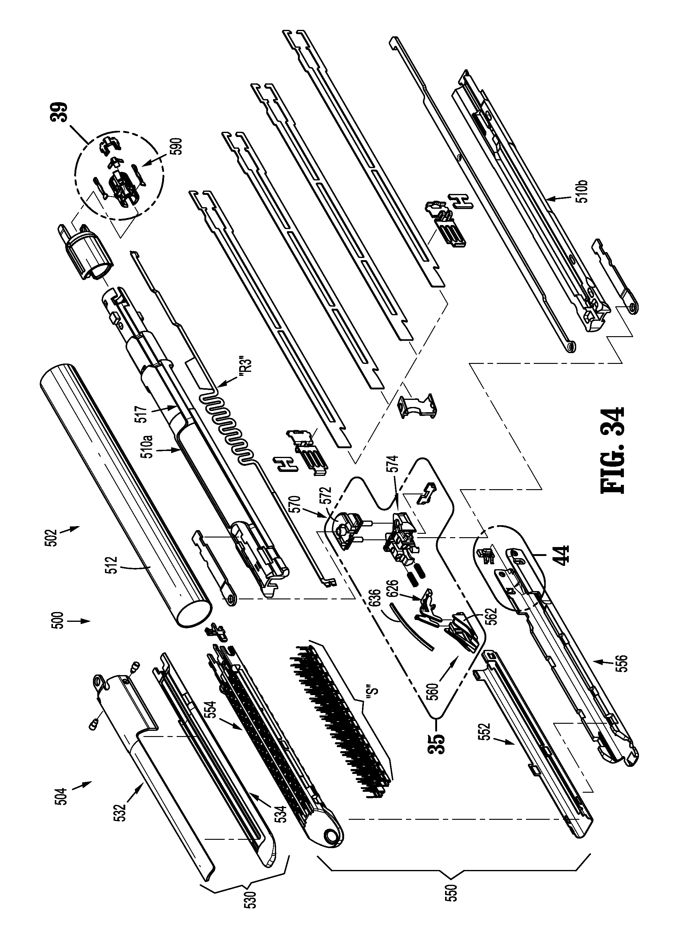
D00021
D00022
D00023

D00024
D00025

D00026

D00027

D00028

D00029

D00030

D00031

D00032

D00033

D00034

D00035

D00036

D00037
XML
uspto.report is an independent third-party trademark research tool that is not affiliated, endorsed, or sponsored by the United States Patent and Trademark Office (USPTO) or any other governmental organization. The information provided by uspto.report is based on publicly available data at the time of writing and is intended for informational purposes only.
While we strive to provide accurate and up-to-date information, we do not guarantee the accuracy, completeness, reliability, or suitability of the information displayed on this site. The use of this site is at your own risk. Any reliance you place on such information is therefore strictly at your own risk.
All official trademark data, including owner information, should be verified by visiting the official USPTO website at www.uspto.gov. This site is not intended to replace professional legal advice and should not be used as a substitute for consulting with a legal professional who is knowledgeable about trademark law.