Ocular implant delivery device and method
Bianchi , et al.
U.S. patent number 10,258,503 [Application Number 15/325,995] was granted by the patent office on 2019-04-16 for ocular implant delivery device and method. This patent grant is currently assigned to ForSight Vision4, Inc.. The grantee listed for this patent is ForSight Vision4, Inc.. Invention is credited to Keith Bianchi, Bill Hartsig, Scott Nunn, Mukund Patel, Mark Sponsel, Lionel Vedrine, Ariel Waitz.


View All Diagrams
| United States Patent | 10,258,503 |
| Bianchi , et al. | April 16, 2019 |
Ocular implant delivery device and method
Abstract
An ocular implant system including an ocular implant sized and shaped to be inserted at least partially into an eye; a carrier member with a shell having a central channel extending at least partially through the shell from a proximal end towards a distal end of the shell. A guide sleeve removably attached within at least a first region of the central channel of the shell and defining a proximal port into the central channel that is accessible from the proximal end of the shell. An implant holder removably attached within at least a second region of the central channel of the shell adjacent to a distal end of the guide sleeve and having a pair of graspers adapted to releasably secure the implant at a distal end of the implant holder. Related devices, systems, and/or methods are described.
| Inventors: | Bianchi; Keith (Menlo Park, CA), Hartsig; Bill (Menlo Park, CA), Nunn; Scott (Menlo Park, CA), Patel; Mukund (Menlo Park, CA), Sponsel; Mark (Menlo Park, CA), Vedrine; Lionel (Menlo Park, CA), Waitz; Ariel (Menlo Park, CA) | ||||||||||
|---|---|---|---|---|---|---|---|---|---|---|---|
| Applicant: |
|
||||||||||
| Assignee: | ForSight Vision4, Inc. (Menlo
Park, CA) |
||||||||||
| Family ID: | 55079028 | ||||||||||
| Appl. No.: | 15/325,995 | ||||||||||
| Filed: | July 15, 2015 | ||||||||||
| PCT Filed: | July 15, 2015 | ||||||||||
| PCT No.: | PCT/US2015/040633 | ||||||||||
| 371(c)(1),(2),(4) Date: | January 12, 2017 | ||||||||||
| PCT Pub. No.: | WO2016/011191 | ||||||||||
| PCT Pub. Date: | January 21, 2016 |
Prior Publication Data
| Document Identifier | Publication Date | |
|---|---|---|
| US 20170165108 A1 | Jun 15, 2017 | |
Related U.S. Patent Documents
| Application Number | Filing Date | Patent Number | Issue Date | ||
|---|---|---|---|---|---|
| 62024682 | Jul 15, 2014 | ||||
| Current U.S. Class: | 1/1 |
| Current CPC Class: | A61F 9/0017 (20130101); A61F 9/007 (20130101); A61F 9/0026 (20130101); A61K 9/0051 (20130101) |
| Current International Class: | A61F 9/00 (20060101); A61K 9/00 (20060101); A61F 9/007 (20060101) |
References Cited [Referenced By]
U.S. Patent Documents
| 2564977 | August 1951 | Hu |
| 2585815 | February 1952 | Mclintock |
| 3232117 | February 1966 | Gilmont |
| 3416530 | December 1968 | Ness |
| 3618604 | November 1971 | Ness |
| 3641237 | February 1972 | Gould et al. |
| 3828777 | August 1974 | Ness |
| 3902495 | September 1975 | Weiss et al. |
| 3916899 | November 1975 | Theeuwes et al. |
| 3949748 | April 1976 | Malmin |
| 3949750 | April 1976 | Freeman |
| 3961628 | June 1976 | Arnold |
| 3977404 | August 1976 | Theeuwes |
| 3995635 | December 1976 | Higuchi et al. |
| 4008719 | February 1977 | Theeuwes et al. |
| 4014333 | March 1977 | McIntyre |
| 4014334 | March 1977 | Theeuwes et al. |
| 4014335 | March 1977 | Arnold |
| 4034756 | July 1977 | Higuchi et al. |
| 4034758 | July 1977 | Theeuwes |
| 4077407 | March 1978 | Theeuwes et al. |
| 4111201 | September 1978 | Theeuwes |
| 4111203 | September 1978 | Theeuwes |
| 4135514 | January 1979 | Zaffaroni et al. |
| 4160452 | July 1979 | Theeuwes |
| 4200098 | April 1980 | Ayer et al. |
| 4220152 | September 1980 | Dresback |
| 4220153 | September 1980 | Dresback |
| 4256108 | March 1981 | Theeuwes |
| 4298000 | November 1981 | Thill et al. |
| 4300557 | November 1981 | Refojo et al. |
| 4309776 | January 1982 | Berguer |
| 4326525 | April 1982 | Swanson et al. |
| 4327725 | May 1982 | Cortese et al. |
| 4439196 | March 1984 | Higuchi |
| 4475916 | October 1984 | Himmelstein |
| 4484922 | November 1984 | Rosenwald |
| 4519801 | May 1985 | Edgren |
| 4609374 | September 1986 | Ayer |
| 4627850 | December 1986 | Deters et al. |
| 4673405 | June 1987 | Guittard et al. |
| 4693886 | September 1987 | Ayer |
| 4712550 | December 1987 | Sinnett |
| 4737150 | April 1988 | Baeumle et al. |
| 4777049 | October 1988 | Magruder et al. |
| 4781675 | November 1988 | White |
| 4863457 | September 1989 | Lee |
| 4865846 | September 1989 | Kaufman |
| 4883459 | November 1989 | Calderon |
| 4959217 | September 1990 | Sanders et al. |
| 5084021 | January 1992 | Baldwin |
| 5098443 | March 1992 | Parel et al. |
| 5128145 | July 1992 | Edgren et al. |
| 5164188 | November 1992 | Wong |
| 5174999 | December 1992 | Magruder et al. |
| 5178622 | January 1993 | Lehner, II |
| 5277912 | January 1994 | Lowe et al. |
| 5282829 | February 1994 | Hermes |
| 5300114 | April 1994 | Gwon et al. |
| 5322691 | June 1994 | Darougar et al. |
| 5334189 | August 1994 | Wade |
| 5336175 | August 1994 | Mames |
| 5378475 | January 1995 | Smith et al. |
| 5413572 | May 1995 | Wong et al. |
| 5443505 | August 1995 | Wong et al. |
| 5476511 | December 1995 | Gwon et al. |
| 5516522 | May 1996 | Peyman et al. |
| 5554132 | September 1996 | Straits et al. |
| 5562915 | October 1996 | Lowe et al. |
| 5681572 | October 1997 | Seare, Jr. |
| 5702414 | December 1997 | Richter et al. |
| 5766242 | June 1998 | Wong et al. |
| 5770076 | June 1998 | Chu et al. |
| 5773019 | June 1998 | Ashton et al. |
| 5797898 | August 1998 | Santini, Jr. et al. |
| 5807581 | September 1998 | Rosenblatt et al. |
| 5824072 | October 1998 | Wong |
| 5830173 | November 1998 | Avery et al. |
| 5830546 | November 1998 | Ehret et al. |
| 5836935 | November 1998 | Ashton et al. |
| 5868697 | February 1999 | Richter et al. |
| 5902598 | May 1999 | Chen et al. |
| 5916584 | June 1999 | O'Donoghue et al. |
| 5928662 | July 1999 | Phillips |
| 5951512 | September 1999 | Dalton |
| 5972369 | October 1999 | Roorda et al. |
| 5985328 | November 1999 | Chu et al. |
| 6001386 | December 1999 | Ashton et al. |
| 6039712 | March 2000 | Fogarty et al. |
| 6096070 | August 2000 | Ragheb et al. |
| 6123861 | September 2000 | Santini, Jr. et al. |
| 6196993 | March 2001 | Cohan et al. |
| 6303290 | October 2001 | Liu et al. |
| 6331313 | December 2001 | Wong et al. |
| 6375972 | April 2002 | Guo et al. |
| 6395300 | May 2002 | Straub et al. |
| 6413540 | July 2002 | Yaacobi |
| 6416777 | July 2002 | Yaacobi |
| 6420399 | July 2002 | Graff et al. |
| 6472162 | October 2002 | Coelho et al. |
| 6605066 | August 2003 | Gravagna et al. |
| 6663668 | December 2003 | Chaouk et al. |
| 6669950 | December 2003 | Yaacobi |
| 6685940 | February 2004 | Andya et al. |
| 6713081 | March 2004 | Robinson et al. |
| 6719750 | April 2004 | Varner et al. |
| 6740077 | May 2004 | Brandau et al. |
| 6756049 | June 2004 | Brubaker et al. |
| 6756058 | June 2004 | Brubaker et al. |
| 6932983 | August 2005 | Straub et al. |
| 6976982 | December 2005 | Santini, Jr. et al. |
| 6986900 | January 2006 | Yaacobi |
| 7026329 | April 2006 | Crain et al. |
| 7074426 | July 2006 | Kochinke |
| 7077848 | July 2006 | de Juan, Jr. et al. |
| 7090681 | August 2006 | Weber et al. |
| 7094226 | August 2006 | Yaacobi |
| 7117870 | October 2006 | Prescott |
| 7141152 | November 2006 | Le Febre |
| 7181287 | February 2007 | Greenberg |
| 7195774 | March 2007 | Carvalho et al. |
| 7195778 | March 2007 | Fleshner-Barak et al. |
| 7211272 | May 2007 | Renner et al. |
| 7252673 | August 2007 | Lim |
| 7276050 | October 2007 | Franklin |
| 7468065 | December 2008 | Weber et al. |
| 7476510 | January 2009 | Kapur et al. |
| 7585517 | September 2009 | Cooper et al. |
| 7615141 | November 2009 | Schwartz et al. |
| 7621907 | November 2009 | Rodstrom |
| 7625927 | December 2009 | Klimko et al. |
| 7678078 | March 2010 | Peyman et al. |
| 7686016 | March 2010 | Wharton et al. |
| 7709049 | May 2010 | Chappa |
| 7753916 | July 2010 | Weber |
| 7883717 | February 2011 | Varner et al. |
| 7893040 | February 2011 | Loftsson et al. |
| 7906136 | March 2011 | Wong et al. |
| 7909800 | March 2011 | Cazzini |
| 7914442 | March 2011 | Gazdzinski |
| 7939094 | May 2011 | Schwarz et al. |
| 7973068 | July 2011 | Demopulos et al. |
| 8313454 | November 2012 | Yaron |
| 8399006 | March 2013 | de Juan, Jr. et al. |
| 8403941 | March 2013 | Peterson et al. |
| 8905963 | December 2014 | de Juan, Jr. et al. |
| 9987163 | June 2018 | Schaller |
| 2002/0026176 | February 2002 | Varner et al. |
| 2002/0086051 | July 2002 | Viscasillas |
| 2002/0106395 | August 2002 | Brubaker |
| 2002/0110591 | August 2002 | Brubaker et al. |
| 2002/0110592 | August 2002 | Brubaker et al. |
| 2002/0110635 | August 2002 | Brubaker et al. |
| 2002/0116009 | August 2002 | Fraser |
| 2003/0003129 | January 2003 | Yaacobi |
| 2003/0005945 | January 2003 | Onishi et al. |
| 2003/0014036 | January 2003 | Varner et al. |
| 2003/0118649 | June 2003 | Gao et al. |
| 2003/0119177 | June 2003 | Gruber et al. |
| 2003/0176854 | September 2003 | Rodstrom |
| 2003/0185872 | October 2003 | Kochinke |
| 2003/0212383 | November 2003 | Cote et al. |
| 2003/0235603 | December 2003 | Schwarz et al. |
| 2004/0011651 | January 2004 | Becker et al. |
| 2004/0019325 | January 2004 | Shekalim |
| 2004/0092911 | May 2004 | Yaacobi |
| 2004/0106906 | June 2004 | Yaacobi |
| 2004/0131654 | July 2004 | Yaacobi |
| 2004/0131655 | July 2004 | Yaacobi |
| 2004/0209359 | October 2004 | Yayon et al. |
| 2004/0230183 | November 2004 | Breegi et al. |
| 2004/0238392 | December 2004 | Peterson et al. |
| 2004/0260380 | December 2004 | Marco et al. |
| 2004/0260381 | December 2004 | Marco et al. |
| 2005/0055031 | March 2005 | Lim |
| 2005/0064010 | March 2005 | Cooper et al. |
| 2005/0074497 | April 2005 | Schultz |
| 2005/0112175 | May 2005 | Yaacobi |
| 2005/0112759 | May 2005 | Radisic et al. |
| 2005/0113806 | May 2005 | De Carvalho et al. |
| 2005/0119737 | June 2005 | Bene et al. |
| 2005/0143363 | June 2005 | De Juan et al. |
| 2005/0154399 | July 2005 | Weber et al. |
| 2005/0163711 | July 2005 | Nycz et al. |
| 2005/0181018 | August 2005 | Peyman |
| 2005/0244467 | November 2005 | Nivaggioli et al. |
| 2005/0244469 | November 2005 | Whitcup et al. |
| 2005/0255144 | November 2005 | Schultz |
| 2005/0256499 | November 2005 | Pettis et al. |
| 2005/0271703 | December 2005 | Anderson et al. |
| 2005/0271706 | December 2005 | Anderson et al. |
| 2005/0276837 | December 2005 | Anderson et al. |
| 2005/0277802 | December 2005 | Larsen et al. |
| 2005/0281861 | December 2005 | Hughes et al. |
| 2005/0281863 | December 2005 | Anderson et al. |
| 2005/0287188 | December 2005 | Anderson et al. |
| 2006/0013835 | January 2006 | Anderson et al. |
| 2006/0039952 | February 2006 | Yaacobi |
| 2006/0052754 | March 2006 | Fields |
| 2006/0057277 | March 2006 | Chappa |
| 2006/0073182 | April 2006 | Wong et al. |
| 2006/0104969 | May 2006 | Oray et al. |
| 2006/0110428 | May 2006 | deJuan et al. |
| 2006/0129215 | June 2006 | Helmus et al. |
| 2006/0154981 | July 2006 | Klimko et al. |
| 2006/0172941 | August 2006 | Rastelli et al. |
| 2006/0182783 | August 2006 | Hughes et al. |
| 2006/0200097 | September 2006 | Humayun et al. |
| 2006/0233858 | October 2006 | Tzekov et al. |
| 2006/0246112 | November 2006 | Snyder et al. |
| 2006/0257450 | November 2006 | Mudumba et al. |
| 2006/0258000 | November 2006 | Allen et al. |
| 2006/0258994 | November 2006 | Avery |
| 2006/0276738 | December 2006 | Becker |
| 2007/0020336 | January 2007 | Loftsson et al. |
| 2007/0021357 | January 2007 | Tobia et al. |
| 2007/0026037 | February 2007 | Kloke et al. |
| 2007/0059336 | March 2007 | Hughes et al. |
| 2007/0071756 | March 2007 | Peyman |
| 2007/0072933 | March 2007 | Peyman |
| 2007/0077270 | April 2007 | Wen |
| 2007/0088414 | April 2007 | Campbell et al. |
| 2007/0119450 | May 2007 | Wharton et al. |
| 2007/0128644 | June 2007 | Munenaka |
| 2007/0131610 | June 2007 | Peng et al. |
| 2007/0131611 | June 2007 | Peng et al. |
| 2007/0134305 | June 2007 | Zilberman |
| 2007/0141111 | June 2007 | Suokas et al. |
| 2007/0191863 | August 2007 | De Juan et al. |
| 2007/0197491 | August 2007 | Robin et al. |
| 2007/0203174 | August 2007 | Klimko et al. |
| 2007/0212397 | September 2007 | Roth |
| 2007/0233037 | October 2007 | Gifford et al. |
| 2007/0235331 | October 2007 | Simpson et al. |
| 2007/0243230 | October 2007 | de Juan et al. |
| 2007/0260201 | November 2007 | Prausnitz et al. |
| 2007/0269487 | November 2007 | de Juan et al. |
| 2008/0003219 | January 2008 | Peyman |
| 2008/0004329 | January 2008 | Jamieson et al. |
| 2008/0020045 | January 2008 | Chappa et al. |
| 2008/0038316 | February 2008 | Wong et al. |
| 2008/0057561 | March 2008 | Takahashi et al. |
| 2008/0066739 | March 2008 | LeMahieu et al. |
| 2008/0066741 | March 2008 | LeMahieu et al. |
| 2008/0069854 | March 2008 | Xiao et al. |
| 2008/0089923 | April 2008 | Burkstrand et al. |
| 2008/0097459 | April 2008 | Kammerlander et al. |
| 2008/0111282 | May 2008 | Xie et al. |
| 2008/0124372 | May 2008 | Hossainy et al. |
| 2008/0139674 | June 2008 | Archambeau et al. |
| 2008/0145406 | June 2008 | Asgharian et al. |
| 2008/0146679 | June 2008 | Archambeau et al. |
| 2008/0147021 | June 2008 | Jani |
| 2008/0152694 | June 2008 | Lobl et al. |
| 2008/0154241 | June 2008 | Burkstrand et al. |
| 2008/0161741 | July 2008 | Bene et al. |
| 2008/0167600 | July 2008 | Peyman |
| 2008/0172014 | July 2008 | Whitcup et al. |
| 2008/0181930 | July 2008 | Rodstrom et al. |
| 2008/0200922 | August 2008 | Brown |
| 2008/0207502 | August 2008 | Rastelli et al. |
| 2008/0213611 | September 2008 | Asgari |
| 2008/0216736 | September 2008 | David |
| 2008/0228127 | September 2008 | Burns et al. |
| 2008/0233053 | September 2008 | Gross et al. |
| 2008/0233171 | September 2008 | Whitcup et al. |
| 2008/0233172 | September 2008 | Whitcup et al. |
| 2008/0233173 | September 2008 | Whitcup et al. |
| 2008/0241219 | October 2008 | Whitcup et al. |
| 2008/0241220 | October 2008 | Whitcup et al. |
| 2008/0241221 | October 2008 | Whitcup et al. |
| 2008/0241222 | October 2008 | Whitcup et al. |
| 2008/0241223 | October 2008 | Nivaggioli et al. |
| 2008/0249501 | October 2008 | Yamasaki |
| 2008/0286338 | November 2008 | Rosenthal et al. |
| 2008/0292679 | November 2008 | Lyons et al. |
| 2009/0005864 | January 2009 | Eggleston |
| 2009/0036827 | February 2009 | Cazzini |
| 2009/0043253 | February 2009 | Podaima |
| 2009/0047335 | February 2009 | Rastelli et al. |
| 2009/0082631 | March 2009 | Cronin et al. |
| 2009/0087494 | April 2009 | Kompella et al. |
| 2009/0092654 | April 2009 | de Juan, Jr. et al. |
| 2009/0093752 | April 2009 | Richard et al. |
| 2009/0099626 | April 2009 | de Juan, Jr. et al. |
| 2009/0104243 | April 2009 | Utkhede et al. |
| 2009/0105749 | April 2009 | de Juan et al. |
| 2009/0124997 | May 2009 | Pettis et al. |
| 2009/0214601 | August 2009 | Chappa et al. |
| 2009/0224064 | September 2009 | Brodbeck et al. |
| 2009/0234449 | September 2009 | De Juan, Jr. et al. |
| 2009/0240215 | September 2009 | Humayun et al. |
| 2009/0247458 | October 2009 | Watson et al. |
| 2009/0258069 | October 2009 | Burnier et al. |
| 2009/0263346 | October 2009 | Taft et al. |
| 2009/0263495 | October 2009 | Watson et al. |
| 2009/0274730 | November 2009 | Watson et al. |
| 2009/0274771 | November 2009 | Watson et al. |
| 2009/0280470 | November 2009 | Fare et al. |
| 2009/0281621 | November 2009 | Becker |
| 2009/0324686 | December 2009 | Cooper et al. |
| 2009/0324687 | December 2009 | Cooper et al. |
| 2009/0324688 | December 2009 | Cooper et al. |
| 2009/0324689 | December 2009 | Cooper et al. |
| 2009/0324690 | December 2009 | Cooper et al. |
| 2009/0326448 | December 2009 | Huo et al. |
| 2010/0003333 | January 2010 | Watson et al. |
| 2010/0004189 | January 2010 | Watson et al. |
| 2010/0008997 | January 2010 | Watson et al. |
| 2010/0009008 | January 2010 | Watson et al. |
| 2010/0010452 | January 2010 | Paques et al. |
| 2010/0011888 | January 2010 | Pawliszyn et al. |
| 2010/0015157 | January 2010 | Andya et al. |
| 2010/0016786 | January 2010 | Drews et al. |
| 2010/0021464 | January 2010 | Archambeau et al. |
| 2010/0022943 | January 2010 | Mauch et al. |
| 2010/0022945 | January 2010 | Rodstrom |
| 2010/0023033 | January 2010 | Mauch et al. |
| 2010/0028442 | February 2010 | Archambeau et al. |
| 2010/0028443 | February 2010 | Watson et al. |
| 2010/0030136 | February 2010 | Dacquay et al. |
| 2010/0034870 | February 2010 | Sim et al. |
| 2010/0083963 | April 2010 | Wharton et al. |
| 2010/0100054 | April 2010 | Cormier et al. |
| 2010/0100104 | April 2010 | Yu et al. |
| 2010/0114017 | May 2010 | Lenker et al. |
| 2010/0114309 | May 2010 | de Juan, Jr. et al. |
| 2010/0168535 | July 2010 | Robinson et al. |
| 2010/0174272 | July 2010 | Weiner |
| 2010/0185205 | July 2010 | Novakovic et al. |
| 2010/0197512 | August 2010 | Trinkle et al. |
| 2010/0216702 | August 2010 | Szkudlinski et al. |
| 2010/0221309 | September 2010 | Myers et al. |
| 2010/0241102 | September 2010 | Ma |
| 2010/0255061 | October 2010 | de Juan, Jr. et al. |
| 2010/0256597 | October 2010 | Prausnitz et al. |
| 2010/0266664 | October 2010 | Asgharian et al. |
| 2010/0286121 | November 2010 | Rohrs et al. |
| 2010/0286791 | November 2010 | Goldsmith |
| 2010/0297046 | November 2010 | Schwartz et al. |
| 2010/0297120 | November 2010 | Beliveau et al. |
| 2010/0297193 | November 2010 | Archambeau et al. |
| 2010/0303917 | December 2010 | Watson et al. |
| 2010/0303918 | December 2010 | Watson et al. |
| 2010/0310664 | December 2010 | Watson et al. |
| 2010/0310665 | December 2010 | Watson et al. |
| 2010/0316723 | December 2010 | Watson et al. |
| 2010/0330146 | December 2010 | Chauhan et al. |
| 2011/0009571 | January 2011 | Taft et al. |
| 2011/0014264 | January 2011 | Helmus et al. |
| 2011/0033933 | February 2011 | Gharib et al. |
| 2011/0034448 | February 2011 | Chang et al. |
| 2011/0081384 | April 2011 | Archambeau et al. |
| 2011/0098686 | April 2011 | Varner et al. |
| 2011/0104155 | May 2011 | Rekik |
| 2011/0108025 | May 2011 | Fink et al. |
| 2011/0111006 | May 2011 | Wong et al. |
| 2011/0112188 | May 2011 | Tobia et al. |
| 2011/0117083 | May 2011 | Bais et al. |
| 2011/0125178 | May 2011 | Drews et al. |
| 2011/0159073 | June 2011 | deJuan et al. |
| 2011/0196317 | August 2011 | Lust et al. |
| 2011/0206646 | August 2011 | Alfonso et al. |
| 2012/0029445 | February 2012 | de Juan, Jr. et al. |
| 2012/0029470 | February 2012 | Juan, Jr. et al. |
| 2012/0245505 | September 2012 | Robinson et al. |
| 2014/0114323 | April 2014 | Kudo |
| 2014/0276901 | September 2014 | Auld |
| 2014/0303637 | October 2014 | Downer |
| 2014/0326249 | November 2014 | Cappiello |
| 2014/0379079 | December 2014 | Ben Nun |
| 2015/0045805 | February 2015 | Kontur |
| 2015/0080846 | March 2015 | de Juan, Jr. et al. |
| 102098993 | Jun 2011 | CN | |||
| 0228185 | Jul 1990 | EP | |||
| 0498471 | Aug 1992 | EP | |||
| 0500143 | Aug 1992 | EP | |||
| 0671165 | Sep 1995 | EP | |||
| 0295248 | Apr 1999 | EP | |||
| 0944658 | Jun 2003 | EP | |||
| 1671624 | Jun 2006 | EP | |||
| 1385452 | Sep 2006 | EP | |||
| 1409065 | Jan 2007 | EP | |||
| 1337284 | Dec 2007 | EP | |||
| 1911481 | Apr 2008 | EP | |||
| 1521572 | Mar 2009 | EP | |||
| WO-88/04573 | Jun 1988 | WO | |||
| WO-90/07545 | Jul 1990 | WO | |||
| WO-95/28984 | Nov 1995 | WO | |||
| WO-97/29850 | Aug 1997 | WO | |||
| WO-98/25982 | Jun 1998 | WO | |||
| WO-00/48660 | Aug 2000 | WO | |||
| WO-01/26714 | Apr 2001 | WO | |||
| WO-01/50943 | Jul 2001 | WO | |||
| WO-03/077972 | Sep 2003 | WO | |||
| WO-03/082188 | Oct 2003 | WO | |||
| WO-2004/000267 | Dec 2003 | WO | |||
| WO-2004/112653 | Dec 2004 | WO | |||
| WO-2005/016401 | Feb 2005 | WO | |||
| WO-2005/027906 | Mar 2005 | WO | |||
| WO-2005/028006 | Mar 2005 | WO | |||
| WO-2005/091922 | Oct 2005 | WO | |||
| WO-2005/107705 | Nov 2005 | WO | |||
| WO-2005/110362 | Nov 2005 | WO | |||
| WO-2005/110436 | Nov 2005 | WO | |||
| WO-2005/110473 | Nov 2005 | WO | |||
| WO-2005/117780 | Dec 2005 | WO | |||
| WO-2006/014484 | Feb 2006 | WO | |||
| WO-2006/015385 | Feb 2006 | WO | |||
| WO-2006/023530 | Mar 2006 | WO | |||
| WO-2006/031358 | Mar 2006 | WO | |||
| WO-2006/031388 | Mar 2006 | WO | |||
| WO-2006/044614 | Apr 2006 | WO | |||
| WO-2006/068838 | Jun 2006 | WO | |||
| WO-2006/071554 | Jul 2006 | WO | |||
| WO-2006/082588 | Aug 2006 | WO | |||
| WO-2006/108054 | Oct 2006 | WO | |||
| WO-2006/125106 | Nov 2006 | WO | |||
| WO-2006/127962 | Nov 2006 | WO | |||
| WO-2006/138609 | Dec 2006 | WO | |||
| WO-2007/012974 | Feb 2007 | WO | |||
| WO-2007/035621 | Mar 2007 | WO | |||
| WO-2007/038453 | Apr 2007 | WO | |||
| WO-2007/044534 | Apr 2007 | WO | |||
| WO-2007/047744 | Apr 2007 | WO | |||
| WO-2007/066339 | Jun 2007 | WO | |||
| WO-2007/084582 | Jul 2007 | WO | |||
| WO-2007/084765 | Jul 2007 | WO | |||
| WO-2007/101204 | Sep 2007 | WO | |||
| WO-2007/117394 | Oct 2007 | WO | |||
| WO-2007/131050 | Nov 2007 | WO | |||
| WO-2007/133761 | Nov 2007 | WO | |||
| WO-2007/133762 | Nov 2007 | WO | |||
| WO-2008/003043 | Jan 2008 | WO | |||
| WO-2008/005240 | Jan 2008 | WO | |||
| WO-2008/011125 | Jan 2008 | WO | |||
| WO-2008/033924 | Mar 2008 | WO | |||
| WO-2008/040062 | Apr 2008 | WO | |||
| WO-2008/045272 | Apr 2008 | WO | |||
| WO-2008/052145 | May 2008 | WO | |||
| WO-2008/060359 | May 2008 | WO | |||
| WO-2008/061043 | May 2008 | WO | |||
| WO-2008/076544 | Jun 2008 | WO | |||
| WO-2008/094989 | Aug 2008 | WO | |||
| WO-2008/115290 | Sep 2008 | WO | |||
| WO-2008/116165 | Sep 2008 | WO | |||
| WO-2008/144340 | Nov 2008 | WO | |||
| WO-2008/144919 | Dec 2008 | WO | |||
| WO-2009/012075 | Jan 2009 | WO | |||
| WO-2009/023615 | Feb 2009 | WO | |||
| WO-2009/046164 | Apr 2009 | WO | |||
| WO-2009/055620 | Apr 2009 | WO | |||
| WO-2009/055671 | Apr 2009 | WO | |||
| WO-2009/055729 | Apr 2009 | WO | |||
| WO-2009/055824 | Apr 2009 | WO | |||
| WO-2009/061607 | May 2009 | WO | |||
| WO-2009/073192 | Jun 2009 | WO | |||
| WO-2009/086112 | Jul 2009 | WO | |||
| WO-2009/089409 | Jul 2009 | WO | |||
| WO-2009/094466 | Jul 2009 | WO | |||
| WO-2009/112878 | Sep 2009 | WO | |||
| WO-2009/117112 | Sep 2009 | WO | |||
| WO-2009/124096 | Oct 2009 | WO | |||
| WO-2009/128932 | Oct 2009 | WO | |||
| WO-2009/134929 | Nov 2009 | WO | |||
| WO-2009/137777 | Nov 2009 | WO | |||
| WO-2010/008424 | Jan 2010 | WO | |||
| WO-2010/021993 | Feb 2010 | WO | |||
| WO-2010/047753 | Apr 2010 | WO | |||
| WO-2010/062628 | Jun 2010 | WO | |||
| WO-2010/066714 | Jun 2010 | WO | |||
| WO-2010/075565 | Jul 2010 | WO | |||
| WO-2010/078063 | Jul 2010 | WO | |||
| WO-2010/080987 | Jul 2010 | WO | |||
| WO-2010/088548 | Aug 2010 | WO | |||
| WO-2010/093945 | Aug 2010 | WO | |||
| WO-2010/095940 | Aug 2010 | WO | |||
| WO-2010/125416 | Nov 2010 | WO | |||
| WO-2010/126908 | Nov 2010 | WO | |||
| WO-2010/135369 | Nov 2010 | WO | |||
| WO-2010/141729 | Dec 2010 | WO | |||
| WO-2010/147661 | Dec 2010 | WO | |||
| WO-2011/008896 | Jan 2011 | WO | |||
| WO-2011/008897 | Jan 2011 | WO | |||
| WO-2011/028850 | Mar 2011 | WO | |||
| WO-2011/034627 | Mar 2011 | WO | |||
| WO-2011/079232 | Jun 2011 | WO | |||
| WO-2012/019136 | Feb 2012 | WO | |||
| WO-2013/082452 | Jun 2013 | WO | |||
| WO-2013/116061 | Aug 2013 | WO | |||
Other References
|
Edelhauser, H et al. "Ophthalmic Drug Delivery Systems for the Treatment of Retinal Diseases Basic Research to Clinical Applications." Investigative Ophthalmology & Visual Science, Nov. 2010. vol. 51, No. 11. pp. 5403-5420. cited by applicant . U.S. Appl. No. 13/615,229, filed Sep. 13, 2012, 2013/0165860. cited by applicant . U.S. Appl. No. 13/814,466, filed Jun. 28, 2013, 2013/0274691. cited by applicant . U.S. Appl. No. 13/814,470, filed Jun. 19, 2013, 2013/0274692. cited by applicant . U.S. Appl. No. 13/849,445, filed Mar. 22, 2013, 2013/0218081. cited by applicant . U.S. Appl. No. 13/988,298, filed Oct. 14, 2013, 2014/0031769. cited by applicant . U.S. Appl. No. 14/129,200, filed Dec. 24, 2013, 2014/0221941. cited by applicant . U.S. Appl. No. 14/212,817, filed Mar. 14, 2014, 2014/0276482. cited by applicant . U.S. Appl. No. 14/236,863, filed Aug. 8, 2014, 2014/0358125. cited by applicant . U.S. Appl. No. 14/376,331, filed Aug. 1, 2014, 2015/0080846. cited by applicant . U.S. Appl. No. 14/713,505, filed May 15, 2015, 2015/0250647. cited by applicant . U.S. Appl. No. 14/753,574, filed Jun. 29, 2015, 2015/0297402. cited by applicant . U.S. Appl. No. 14/937,754, filed Nov. 10, 2015, 2016/0128867. cited by applicant . U.S. Appl. No. 14/973,311, filed Dec. 17, 2015, 2016/0101046. cited by applicant . U.S. Appl. No. 15/060,467, filed Mar. 3, 2016, 2016/0258855. cited by applicant . U.S. Appl. No. 15/102,191, filed Jun. 6, 2016, 2016/0302965. cited by applicant . U.S. Appl. No. 15/270,493, filed Sep. 20, 2016, 2017/0071938. cited by applicant . PCT/US2015/059990, Nov. 10, 2015, WO 2016/077371. cited by applicant . U.S. Appl. No. 15/386,586, filed Dec. 21, 2016, 2017-0165110. cited by applicant . U.S. Appl. No. 15/606,647, filed May 26, 2017, 2017-0258634. cited by applicant . PCT/US2016/062944, Nov. 18, 2016, WO 2017/087902. cited by applicant . PCT/US2017/026151, Apr. 5, 2017, WO 2017/176886. cited by applicant . Andrews, "Effect of nonsteroidal anti-inflammatory drugs on LFA-1 and ICAM-1 expression in gastric mucosa," Am J Physiol. Apr. 1994;266(4 Pt 1):G657-664. cited by applicant . Avery et al., "Intravitreal bevacizumab (Avastin) in the treatment of proliferative diabetic retinopathy," Ophthalmology. Oct. 2006, 113(10):1695-1705.e6. cited by applicant . Bakri et al., "The effect of intravitreal triamcinolone acetonide on intraocular pressure," Ophthalmic Surgery, Lasers and Imaging, Sep./Oct. 2003; 34(5): 386-390. cited by applicant . Bird et al., Transport Phenomena, John Wiley & Sons, Inc., New York, 1960, pp. 196-201. cited by applicant . Block et al., "Solubility and dissolution of triamcinolone acetonide," Journal of Pharmaceutical Sciences,Apr. 1963; 62(4):617-621. cited by applicant . Castro et al., "Effect of COX inhibitors on VEGF-induced retinal vascular leakage and experimental corneal and choroidal neovascularization," Exp Eye Res. Aug. 2004;79(2):275-285. cited by applicant . Chirila et al., "The Vitreous Humor" in Handbook of Biomaterial Properties, eds. Black & Hastings. Chapman & Hall, London, 1998; pp. 125-131. cited by applicant . Cousins et al., "Program # 1251--Targeting Complement Factor 5 in Combination with Vascular Endothelial Growth Factor (VEGF) Inhibition for Neovascular Age Related Macular Degeneration (AMD): Results of a Phase 1 Study," [Presentation Abstract], AMD Clinical Trials Session # 220, May 3, 2010. 2 pages. cited by applicant . Deissler et al., "VEGF-induced effects on proliferation, migration and tight junctions are restored by ranibizumab (Lucentis) in microvascular retinal endothelial cells,"Br J Ophthalmol 2008;92:839-843. cited by applicant . Donoso et al., "The role of inflammation in the pathogenesis of age-related macular degeneration," Surv Ophthalmol. Mar.-Apr. 2006;51(2):137-52. cited by applicant . European Medicine Agency, Scientific Discussion; retrieved from the Internet; <http://www.ema.europa.eu/docs/en_GB/document_library/EPAR_-- _Scientific_Discussion/human/000715/WC500043550.pdf>, EMEA 2007, 54 pages total. 2007. cited by applicant . Funatsu et al. "Association of vitreous inflammatory factors with diabetic macular edema," Ophthalmology 2009;116:73-79. cited by applicant . Gaudreault et al., "Preclinical Pharmacokinetics of Ranibizumab (rhuFabV2) after a Single Intravitreal Administration," Investigative Ophthalmology and Visual Science. 2005;46:726-733. Retrieved from the Internet: <<http://www.iovs.org/cgi/reprint/46/2/726>>. cited by applicant . Gillies et al., "Intravitreal triamcinolone for refractory diabetic macular edema: two-year results of a double-masked, placebo-controlled, randomized clinical trial," Ophthalmology. Sep. 2006;113(9):1533-1538. cited by applicant . Hastedt & Wright, "Diffusion in porous materials above the percolation threshold," Pharm. Res. Sep. 1990; 7(9):893-901 (1990). cited by applicant . Heier et al, "Ketorolac versus prednisolone versus combination therapy in the treatment of acute pseudophakic cystoid macular edema," Ophthalmology. Nov. 2000;107(11):2034-2038 ;discussion 2039. cited by applicant . Jena et al., "A Novel Technique for Surface Area and Particle Size Determination of Components of Fuel Cells and Batteries," Porous Materials, Inc., Dec. 2006, 3 pages total. Downloaded from the Internet: <<http://www.pmiapp.com/publications/docs/A_Novel_technique_for_sur- face_area.pdf>>. cited by applicant . Kang et al., "Inhibitory effects of anti-inflammatory drugs on interleukin-6 bioactivity," Biol Pharm Bull. Jun. 2001;24(6):701-703. cited by applicant . Lopez-Armada et al., "Modulation of cell recruitment by anti-inflammatory agents in antigen-induced arthritis," Ann Rheum Dis Nov. 2002;61(11):1027-1030. cited by applicant . Luncentis, INN-Ranibizumab, "Scientific Discussion," European Medicines Agency ; retrieved from the Internet<http://www.ema.europa.eu/docs/en_GB/document_library/EPAR_-_ Assessment_Report_-_Variation/human/000715/WC500101009.pdf>. Oct. 21, 2010. 32 pages. cited by applicant . Metal Powder Industries Federation, Porous Metal Design Guidebook, 2007, 24 pages total. Downloaded from the Internet: <<http://www.mpif.org/DesignCenter/porous.pdf>>. cited by applicant . MOTT Corporation, "Sintered Metal Powder Media," American Filtration & Separation Society 2007, 2 pages total. Downloaded from the Internet:<<http://www.afssociety.org/education/0907oneminute.htm>- ;>. cited by applicant . Navarro, "The Optical Design of the Human Eye: a Critical Review," J Optom, Jan.-Mar. 2009 2(1): 3-18. cited by applicant . Okabe et al., "Intraocular tissue distribution of betamethasone after intrascleral administration using a non-biodegradable sustained drug delivery device," Investigative Ophthalmology and Visual Science. 2003;44:2702-2707. Downloaded from the Internet: <<http://www.iovs.org/cgi/reprint/44/6/2702>>. cited by applicant . Rosenfeld, "The Latest Research: Intravitreal Bevacizumab for Proliferative Diabetic Retinopathy," Review of Ophthalmology's Retina Online, Feb. 2006; retrieved from the Internet: http://www.revophth.com/archive/newsletter/0206_retina.htm. 2 pages. cited by applicant . Smith et al., "Spectrophotometric determination of pKa values for fluorescein using activity coefficient corrections," WaterSA 2002; 28(4):395-402. cited by applicant . Soheilian et al., "Pilot Study of Intravitreal Injection of Diclofenac for Treatment of Macular Edema of Various Etiologies," Retina, Mar. 2010; 30(3): 509-515. cited by applicant . Theodossiadis et al., "Intravitreal administration of the anti-tumor necrosis factor agent infliximab for neovascular age-related macular degeneration," Am J Ophthalmol. May 2009;147(5):825-830. cited by applicant . Williams et al., "Treating Diabetic Macular Edema With Ocular NSAIDs," Retinal Physician, Nov. 2007; retrieved from the Internet Nov. 11, 2007. http://www.retinalphysician.com/article.aspx?article=101096>, 5 pages total. cited by applicant . U.S. Appl. No. 15/730,537, filed Oct. 11, 2017, 2018-0243131. cited by applicant . U.S. Appl. No. 15/807,396, filed Nov. 8, 2017, 2018-0292403. cited by applicant . U.S. Appl. No. 15/840,965, filed Dec. 13, 2017, 2018-0161202. cited by applicant . U.S. Appl. No. 15/877,146, filed Jan. 22, 2018, 2018-0243130. cited by applicant . U.S. Appl. No. 15/880,180, filed Jan. 25, 2018, 2018-0147204. cited by applicant . U.S. Appl. No. 16/004,085, filed Jun. 8, 2018, 2018-0289542. cited by applicant. |
Primary Examiner: Vu; Quynh-Nhu H.
Attorney, Agent or Firm: Mintz Levin Cohn Ferris Glovsky and Popeo, P.C.
Parent Case Text
CROSS-REFERENCE TO PRIORITY DOCUMENTS
This application is a national phase entry of co-pending PCT Application Serial No. PCT/US2015/040633, filed Jul. 15, 2015, which claims priority under 35 U.S.C. .sctn. 119(e) of U.S. Provisional Patent Application Ser. No. 62/024,682, filed Jul. 15, 2014. The disclosures of the PCT patent application and provisional patent application are hereby incorporated by reference in their entireties.
Claims
What is claimed:
1. An ocular implant handling system, comprising: a carrier member comprising: a shell having a central channel extending at least partially through the shell from a proximal end towards a distal end of the shell; a guide sleeve removably attached within at least a first region of the central channel of the shell, the guide sleeve defining a proximal port into the central channel that is accessible from the proximal end of the shell; and an implant holder removably attached within at least a second region of the central channel of the shell adjacent to a distal end of the guide sleeve, the implant holder having a pair of graspers adapted to releasably secure an implant at a distal end of the implant holder.
2. The system of claim 1, wherein the guide sleeve has at least one guide sleeve slot sized and shaped to receive a corresponding tab of the shell that projects into the at least one guide sleeve slot when the guide sleeve is positioned within the central channel.
3. The system of claim 2, wherein an edge of the guide sleeve slot abuts a distal end of the shell tab when in a locked first state.
4. The system of claim 1, wherein a region of the guide sleeve has a u-shaped slot forming a guide sleeve tab.
5. The system of claim 4, wherein the guide sleeve tab has a free end that projects inwards towards a longitudinal axis of the guide sleeve positioned within the central channel.
6. The system of claim 1, wherein a proximal end region of the implant holder has a pair of tabs formed by a pair of u-shaped slots.
7. The system of claim 6, wherein each of the pair of tabs has a projection on its inner surface.
8. The system of claim 7, wherein the first arm and the second arm each have a recess on its outer surface.
9. The system of claim 8, wherein each of the recesses are configured to receive the projections when the first and second arms are inserted through the interior of the implant holder.
10. The system of claim 1, wherein the central channel terminates at a window extending through a distal end region of the shell, and wherein the pair of graspers secure an implant within the window.
11. The system of claim 10, wherein the implant has an elongate axis extending through a center of the implant from a proximal end to the distal end of the implant, wherein the elongate axis of the implant is concentric with an elongate axis of the central channel.
12. The system of claim 1, wherein a proximal end of the guide sleeve is relatively flush with the proximal end of the shell.
13. The system of claim 1, wherein a proximal end of the guide sleeve extends a distance beyond the proximal end of the shell.
14. The system of claim 13, wherein the proximal end of the guide sleeve incorporates a gripping element.
15. The system of claim 14, wherein the gripping element has an ergonomic size and shape that facilitates grasping by a user.
16. The system of claim 1, wherein the guide sleeve has a generally cylindrical shape.
17. The system of claim 1, wherein the guide sleeve has a c-shaped cross section such that a first side of the guide sleeve is cylindrical and a second side of the guide sleeve is discontinuous.
18. The system of claim 17, wherein the discontinuous second side of the guide sleeve aligns with the first side of the shell and the central channel.
19. The system of claim 1, further comprising an ocular implant comprising a retention structure and a reservoir sized and shaped to be inserted at least partially into an eye such that the implant can deliver a drug from the reservoir into the eye.
20. An ocular implant handling and filling system comprising: a carrier member comprising: a shell having a central channel extending at least partially through the shell from a proximal end towards a distal end of the shell; and a guide sleeve removably attached within at least a first region of the central channel of the shell, the guide sleeve defining a proximal port into the central channel that is accessible from the proximal end of the shell; an implant holder removably attached within at least a second region of the central channel of the shell adjacent to a distal end of the guide sleeve, the implant holder having a pair of graspers adapted to releasably secure an ocular implant at a distal end of the implant holder; and a fill syringe sized and shaped to be inserted through the port into the central channel through the guide sleeve.
Description
FIELD
The subject matter described herein relates to methods, systems and devices for holding, filling and/or delivering implantable drug delivery devices.
BACKGROUND
Implantable devices can be used to provide a therapeutic agent to one or more locations of a patient. The implant may have a reservoir for holding therapeutic agent, and a structure to retain the implant at a desired location of the patient. The agent can be released from the implant into the patient to provide a therapeutic benefit. After an amount of time, the amount of fluid released can be less than ideal, and the fluid of the implant may be replaced, refilled, or exchanged to provide additional amounts of therapeutic agent to extend the therapy. A drug delivery device may be implanted into a patient's eye for the delivery of drug to the eye in treating eye disease. U.S. Pat. No. 8,399,006, which is incorporated herein by reference, describes an example of an implantable drug delivery device for the eye.
There remains a need for devices and methods for filling implants with drug and for holding the implantable device during insertion of the device into the patient.
SUMMARY
Implementations of the present disclosure provide methods, systems and devices for filling implants with drug and for holding the implantable device during insertion of the device into the patient. In many implementations, the methods, systems and devices provide for injection of a therapeutic agent into an implantable device prior to insertion. The implantable device can be manufactured and provided to a clinic without a therapeutic agent, such that the therapeutic agent can be placed in the implantable device in the clinic prior to insertion.
In one aspect, provided is an ocular implant system having an ocular implant having a retention structure and a reservoir sized and shaped to be inserted at least partially into an eye such that the implant can deliver a drug from the reservoir into the eye. The system has a carrier member with a shell having a central channel extending at least partially through the shell from a proximal end towards a distal end of the shell; and a guide sleeve removably attached within at least a first region of the central channel of the shell, the guide sleeve defining a proximal port into the central channel that is accessible from the proximal end of the shell. The system includes an implant holder removably attached within at least a second region of the central channel of the shell adjacent to a distal end of the guide sleeve. The implant holder has a pair of graspers adapted to releasably secure the implant at a distal end of the implant holder.
The system can further include a fill syringe sized and shaped to be inserted through the port into the central channel through the guide sleeve to fill the implant with one or more therapeutic agents. The guide sleeve can simultaneously detach from the shell and attach to the fill syringe when the fill syringe is inserted into the central channel. The guide sleeve can have at least one guide sleeve slot sized and shaped to receive a corresponding tab of the shell that projects into the at least one guide sleeve slot when the guide sleeve is positioned within the central channel. An edge of the guide sleeve slot can abut a distal end of the shell tab when in a locked first state. The fill syringe can have a needle assembly having an outer surface, and optionally the fill syringe can be pre-filled with the one or more therapeutic agents. Insertion of the fill syringe through the guide sleeve positioned within the central channel can cause contact between the outer surface of the needle assembly and an inner surface of the shell tab urging the shell tab to flex outward away from the guide sleeve slot into an unlocked second state wherein the edge of the guide sleeve slot no longer abuts the distal end of the shell tab.
A region of the guide sleeve can have a u-shaped slot forming a guide sleeve tab. The guide sleeve tab can have a free end that projects inwards towards a longitudinal axis of the guide sleeve positioned within the central channel. The fill syringe can have a first portion having a first outer diameter and a second portion having a second outer diameter. The first portion can be located distal to the second portion and the first outer diameter can be larger than the second outer diameter. Distal advancement of the fill syringe through the guide sleeve can cause the first portion of the fill syringe to abut against the free end of the guide sleeve tab and can urge the guide sleeve tab outward away from the longitudinal axis of the guide sleeve. Further distal advancement of the fill syringe through the guide sleeve can advance the first portion distal to the free end of the guide sleeve tab such that the free end flexes back inward toward the longitudinal axis and towards the smaller diameter second portion located proximal to the first portion. The free end of the guide sleeve tab can abut a proximal ledge of the first portion locking the guide sleeve to the fill syringe. The implant holder can have an interior configured to receive at least a portion of the needle assembly of the fill syringe.
The pair of graspers can extend substantially around the retention structure of the implant such that a fill port of the implant is available from within the interior of the implant holder. A first grasper of the pair of graspers can have a first protrusion and a second grasper of the pair of graspers can have a second protrusion. The first and second protrusions can be configured to be received within an indentation distal to the retention structure of the implant such that the retention structure is held within the interior of the implant holder and the reservoir extends distal to the implant holder.
The system can further include a handle member usable for inserting the implant into an eye. The implant holder can be configured to interchangeably couple with the carrier member and the handle member. The handle member can include an elongated proximal portion and a distal attachment portion. The distal attachment portion can releasably attach to the implant holder. The distal attachment portion of the handle member can be sized and shaped to be inserted through the central channel after the fill syringe and guide sleeve coupled to the fill syringe are removed from the shell. The distal attachment portion can include a first arm and a second arm. A proximal end region of the implant holder can have a pair of tabs formed by a pair of u-shaped slots. Each of the pair of tabs can have a projection on its inner surface. The first arm and the second arm can each have a recess on its outer surface. Each of the recesses can be configured to receive the projections when the first and second arms are inserted through the interior of the implant holder.
The handle member can further include an actuator configured to detach the implant from the implant holder. When the actuator is in a first state, the pair of graspers can be positioned adjacent one another and surround the implant. When the actuator is in a second state, the pair of graspers can be urged away from one another and release the implant. The actuator can include an actuator element, a spring-held slider member, and a pair of arms. The actuator element can have a projection extending from a lower surface and have a ramped surface. Movement of the actuator element towards the upper surface of the handle can cause the ramped surface to slide against a corresponding ramped surface of the slider member urging the slider member in a proximal direction relative to the pair of arms. The slider member can have a forked region interfaced with the pair of arms such that proximal movement of the slider member causes the pair of arms to open in a scissor-like movement. Opening the pair of arms can urge the pair of graspers away from one another releasing the implant held therebetween.
The central channel can terminate at a window extending through a distal end region of the shell. The pair of graspers can secure the implant within the window. The implant can have an elongate axis extending through a center of the implant from a proximal end to the distal end of the implant. The elongate axis of the implant can be concentric with an elongate axis of the central channel. A proximal end of the guide sleeve can be relatively flush with the proximal end of the shell. A proximal end of the guide sleeve can extend a distance beyond the proximal end of the shell. The proximal end of the guide sleeve can incorporate a gripping element. The gripping element can have an ergonomic size and shape that facilitates grasping by a user. The guide sleeve can have a generally cylindrical shape. The guide sleeve can have a c-shaped cross section such that a first side of the guide sleeve is cylindrical and a second side of the guide sleeve is discontinuous. The discontinuous second side of the guide sleeve can align with the first side of the shell and the central channel.
In an interrelated aspect, provided is an ocular implant handling system having a carrier member. The carrier member has a shell having a central channel extending at least partially through the shell from a proximal end towards a distal end of the shell. The carrier member has a guide sleeve removably attached within at least a first region of the central channel of the shell. The guide sleeve defines a proximal port into the central channel that is accessible from the proximal end of the shell. The carrier member has an implant holder removably attached within at least a second region of the central channel of the shell adjacent to a distal end of the guide sleeve. The implant holder has a pair of graspers adapted to releasably secure an implant at a distal end of the implant holder.
The handle member can be usable for inserting an implant into an eye. The system can further include an ocular implant having a retention structure and a reservoir sized and shaped to be inserted at least partially into an eye such that the implant can deliver a drug from the reservoir into the eye.
The system can further include a fill syringe sized and shaped to be inserted through the port into the central channel through the guide sleeve. The guide sleeve can simultaneously detach from the shell and attach to the fill syringe when the fill syringe is inserted into the central channel. The guide sleeve can have at least one guide sleeve slot sized and shaped to receive a corresponding tab of the shell that projects into the at least one guide sleeve slot when the guide sleeve is positioned within the central channel. An edge of the guide sleeve slot can abut a distal end of the shell tab when in a locked first state. The fill syringe can have a needle assembly having an outer surface. Insertion of the fill syringe through the guide sleeve positioned within the central channel can cause contact between the outer surface of the needle assembly and an inner surface of the shell tab urging the shell tab to flex outward away from the guide sleeve slot into an unlocked second state wherein the edge of the guide sleeve slot no longer abuts the distal end of the shell tab. A region of the guide sleeve can have a u-shaped slot forming a guide sleeve tab. The guide sleeve tab can have a free end that projects inwards towards a longitudinal axis of the guide sleeve positioned within the central channel.
The fill syringe can have a first portion having a first outer diameter and a second portion having a second outer diameter. The first portion can be located distal to the second portion and the first outer diameter can be larger than the second outer diameter. Distal advancement of the fill syringe through the guide sleeve can cause the first portion of the fill syringe to abut against the free end of the guide sleeve tab and urge the guide sleeve tab outward away from the longitudinal axis of the guide sleeve. Further distal advancement of the fill syringe through the guide sleeve can advance the first portion distal to the free end of the guide sleeve tab such that the free end flexes back inward toward the longitudinal axis and towards the smaller diameter second portion located proximal to the first portion. The free end of the guide sleeve tab can abut a proximal ledge of the first portion locking the guide sleeve to the fill syringe.
The implant holder can have an interior configured to receive at least a portion of the needle assembly of the fill syringe. The pair of graspers can extend substantially around the retention structure of the implant such that a fill port of the implant is available from within the interior of the implant holder. A first grasper of the pair of graspers can have a first protrusion and a second grasper of the pair of graspers can have a second protrusion. The first and second protrusions can be configured to be received within an indentation distal to the retention structure of the implant such that the retention structure is held within the interior of the implant holder and the reservoir extends distal to the implant holder.
The handle member can include an elongated proximal portion and a distal attachment portion. The distal attachment portion can releasably attach to the implant holder. The distal attachment portion of the handle member can be sized and shaped to be inserted through the central channel after the fill syringe and guide sleeve coupled to the fill syringe are removed from the shell. The distal attachment portion can include a first arm and a second arm. A proximal end region of the implant holder can have a pair of tabs formed by a pair of u-shaped slots. Each of the pair of tabs can have a projection on its inner surface. The first arm and the second arm can each have a recess on its outer surface. Each of the recesses can be configured to receive the projections when the first and second arms are inserted through the interior of the implant holder.
The handle member can further include an actuator configured to detach the implant from the implant holder. When the actuator is in a first state, the pair of graspers can be positioned adjacent one another and surround the implant. When the actuator is in a second state, the pair of graspers can be urged away from one another and release the implant. The actuator can include an actuator element, a spring-held slider member, and a pair of arms. The actuator element can have a projection extending from a lower surface and having a ramped surface. Movement of the actuator element towards the upper surface of the handle can cause the ramped surface to slide against a corresponding ramped surface of the slider member urging the slider member in a proximal direction relative to the pair of arms. The slider member can have a forked region interfaced with the pair of arms such that proximal movement of the slider member causes the pair of arms to open in a scissor-like movement. Opening the pair of arms can urge the pair of graspers away from one another releasing an implant held therebetween.
The central channel can terminate at a window extending through a distal end region of the shell. The pair of graspers can secure an implant within the window. An implant can have an elongate axis extending through a center of the implant from a proximal end to the distal end of the implant. The elongate axis of the implant can be concentric with an elongate axis of the central channel. A proximal end of the guide sleeve can be relatively flush with the proximal end of the shell. A proximal end of the guide sleeve can extend a distance beyond the proximal end of the shell. The proximal end of the guide sleeve can incorporate a gripping element. The gripping element can have an ergonomic size and shape that facilitates grasping by a user. The guide sleeve can have a generally cylindrical shape. The guide sleeve can have a c-shaped cross section such that a first side of the guide sleeve is cylindrical and a second side of the guide sleeve is discontinuous. The discontinuous second side of the guide sleeve can align with the first side of the shell and the central channel.
In an interrelated aspect, provided is an ocular implant handling and delivery system. The system includes a handle member usable for inserting an ocular implant into an eye having an elongated proximal portion and a distal attachment portion. The system includes a carrier member having a shell having a central channel extending at least partially through the shell from a proximal end towards a distal end of the shell; and a guide sleeve removably attached within at least a first region of the central channel of the shell. The guide sleeve defines a proximal port into the central channel that is accessible from the proximal end of the shell. The system includes an implant holder removably attached within at least a second region of the central channel of the shell adjacent to a distal end of the guide sleeve. The implant holder has a pair of graspers adapted to releasably secure the ocular implant at a distal end of the implant holder. The implant holder is configured to interchangeably couple with the carrier member and the handle member.
The system can further include the ocular implant. The ocular implant can include a retention structure and a reservoir sized and can be shaped to be inserted at least partially into an eye such that the ocular implant can deliver a drug from the reservoir into the eye.
In an interrelated aspect, provided is an ocular implant handling and filling system. The system includes a carrier member having a shell having a central channel extending at least partially through the shell from a proximal end towards a distal end of the shell; and a guide sleeve removably attached within at least a first region of the central channel of the shell. The guide sleeve defines a proximal port into the central channel that is accessible from the proximal end of the shell. The system includes an implant holder removably attached within at least a second region of the central channel of the shell adjacent to a distal end of the guide sleeve. The implant holder has a pair of graspers adapted to releasably secure an ocular implant at a distal end of the implant holder. The system includes a fill syringe sized and shaped to be inserted through the port into the central channel through the guide sleeve.
The system can further includes the ocular implant having a retention structure and a reservoir sized and shaped to be inserted at least partially into an eye such that the implant can deliver a drug from the reservoir into the eye. The system can further include a handle member usable for inserting an ocular implant into an eye. The handle member can include an elongated proximal portion and a distal attachment portion. The implant holder can be configured to interchangeably couple with the carrier member and the handle member.
In an interrelated aspect, provided is a handling and filling system having a carrier member. The carrier member includes a shell having a central channel extending at least partially through the shell from a proximal end towards a distal end of the shell. The carrier member includes a guide sleeve removably attached within at least a first region of the central channel of the shell. The guide sleeve defines a proximal port into the central channel that is accessible from the proximal end of the shell. The system includes an implant holder removably attached within at least a second region of the central channel of the shell adjacent to a distal end of the guide sleeve. The implant holder has a pair of graspers adapted to releasably secure an implant at a distal end of the implant holder. The system includes a fill syringe sized and shaped to be inserted through the port into the central channel through the guide sleeve. The system includes a handle member usable for inserting the implant into an eye. The handle member includes an elongated proximal portion and a distal attachment portion. The implant holder is configured to interchangeably couple with the carrier member and the handle member.
The system can further include the ocular implant. The ocular implant can include a retention structure and a reservoir sized and shaped to be inserted at least partially into an eye such that the ocular implant can deliver a drug from the reservoir into the eye.
In an interrelated aspect, provided is a fill syringe sized and shaped to insert through a region of a carrier member holding an ocular implant. The fill syringe is configured to inject one or more therapeutic agents from the fill syringe into a reservoir of the ocular implant.
The carrier member can include a shell having a central channel extending at least partially through the shell from a proximal end towards a distal end of the shell. The carrier member can include a guide sleeve removably attached within at least a first region of the central channel of the shell. The guide sleeve can define a proximal port into the central channel that is accessible from the proximal end of the shell. A portion of the fill syringe can lock with a portion of the guide sleeve when the fill syringe is inserted through the central channel of the shell. Withdrawal of the fill syringe from the carrier member can remove the guide sleeve from the shell. The fill syringe can be pre-filled with the one or more therapeutic agents.
The above-noted aspects and features may be implemented in systems, apparatus, and/or methods, depending on the desired configuration. The details of one or more variations of the subject matter described herein are set forth in the accompanying drawings and the description below. Features and advantages of the subject matter described herein will be apparent from the description and drawings, and from the claims.
BRIEF DESCRIPTION OF THE DRAWINGS
In the drawings,
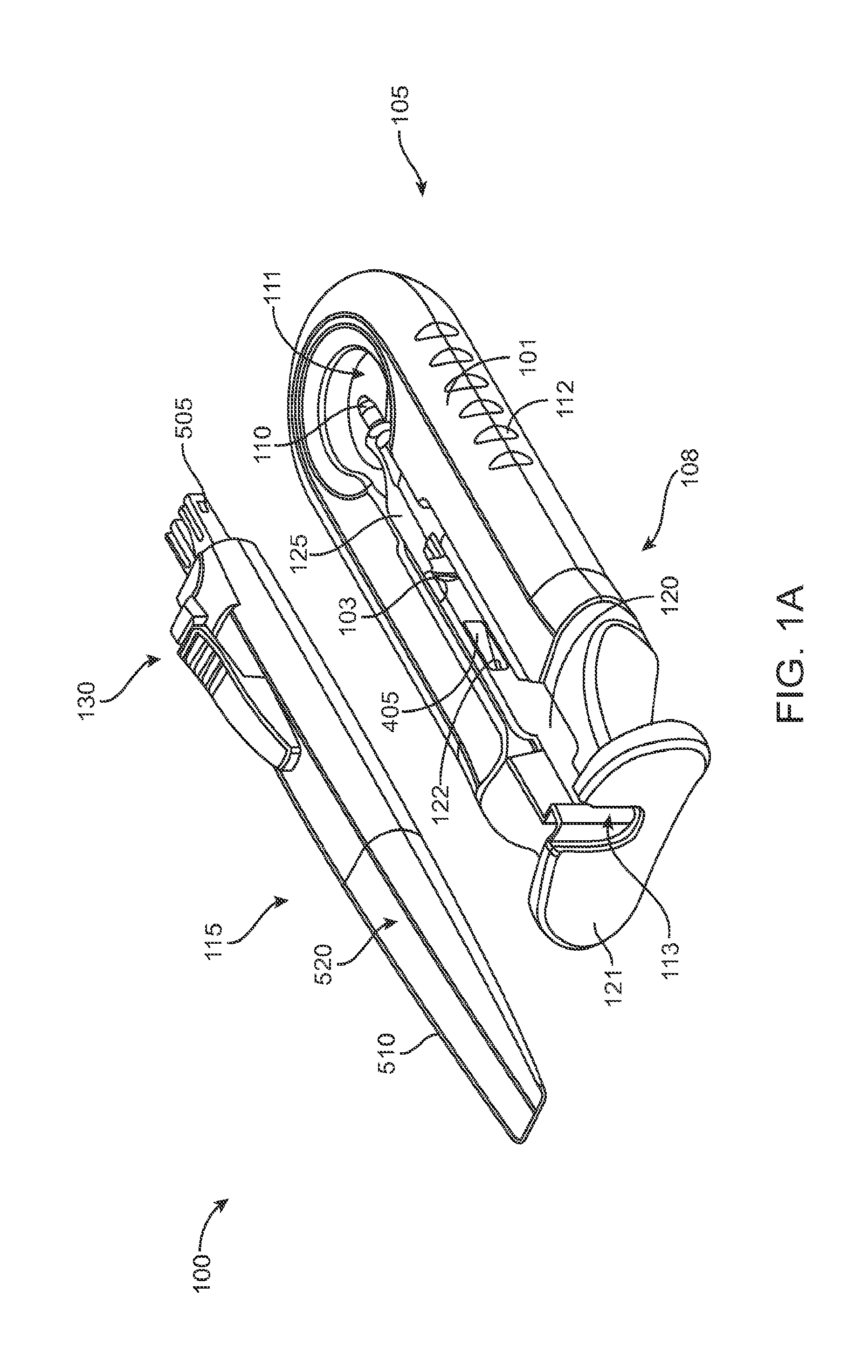
FIG. 1A shows an implementation of a system for holding an ocular implant, filling the ocular implant with a drug and inserting the filled implant into an eye;
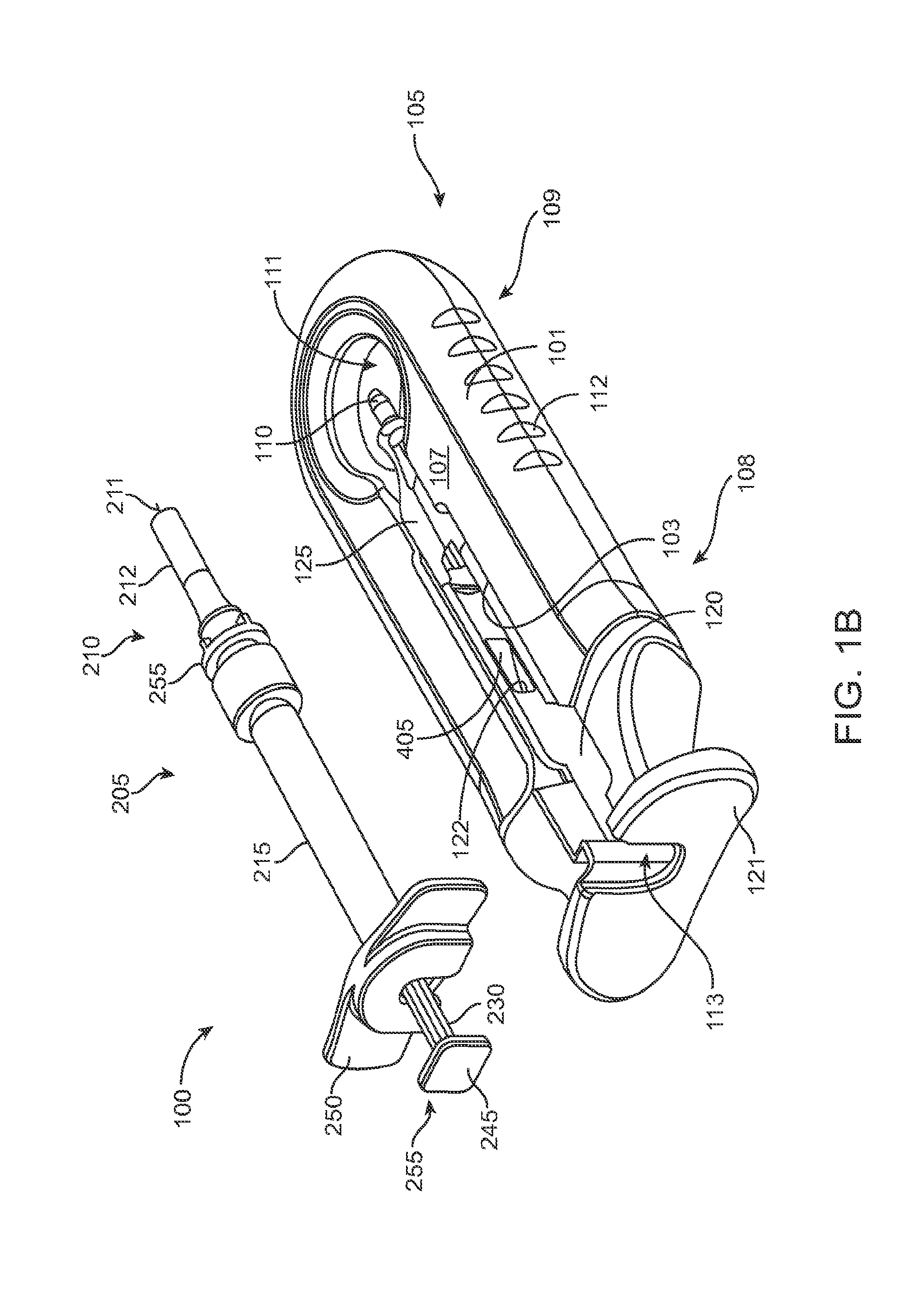
FIG. 1B shows an implementation of a system including a fill syringe;
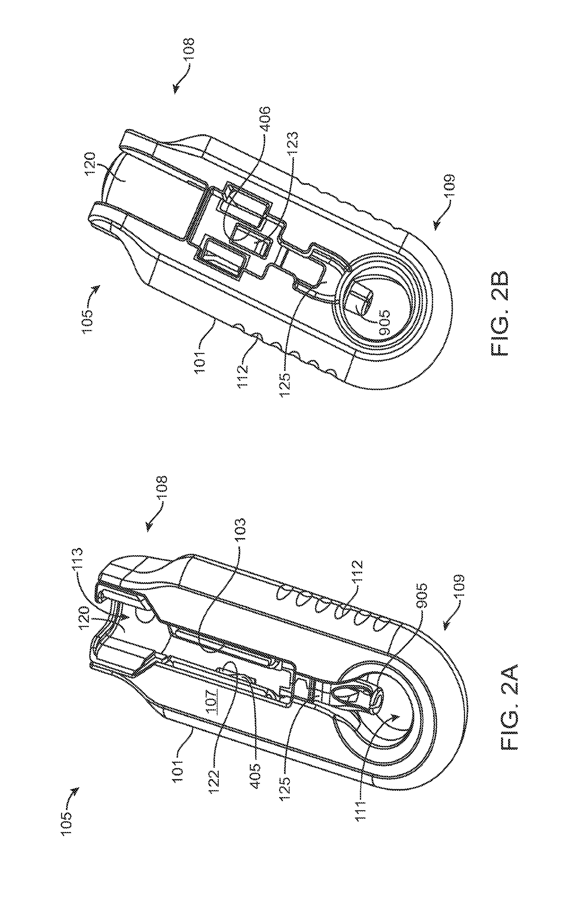
FIGS. 2A and 2B show front and back sides, respectively, of a carrier of the system of FIG. 1A;
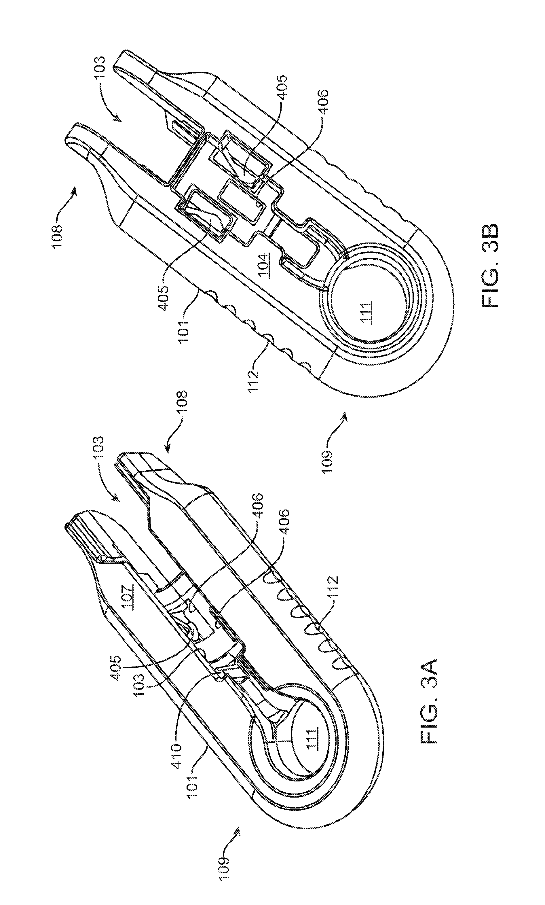
FIGS. 3A and 3B show front and back sides, respectively, of a shell of the system in FIG. 1A;
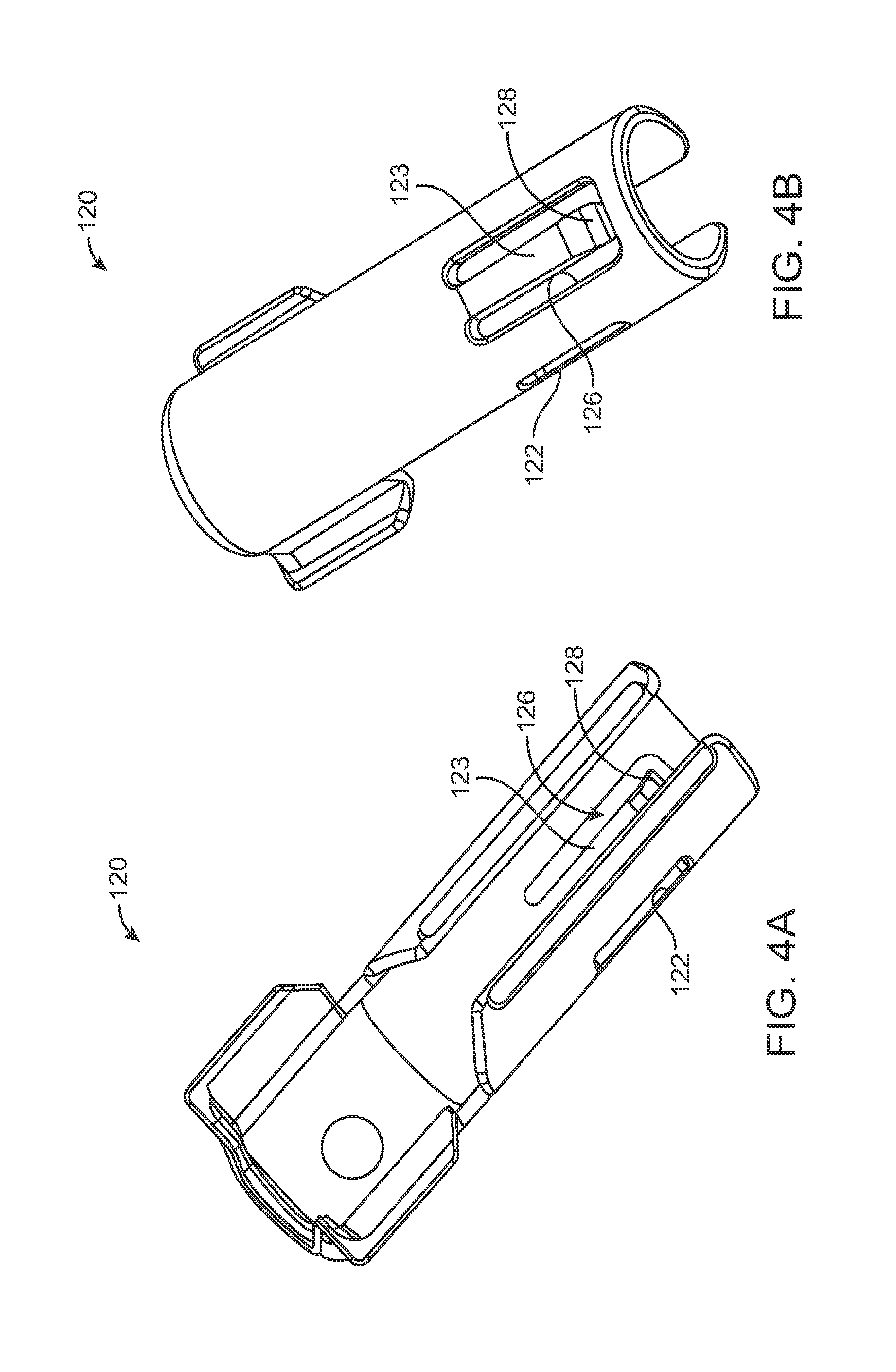
FIGS. 4A and 4B show front and back sides, respectively, of a guide sleeve for use in a system;
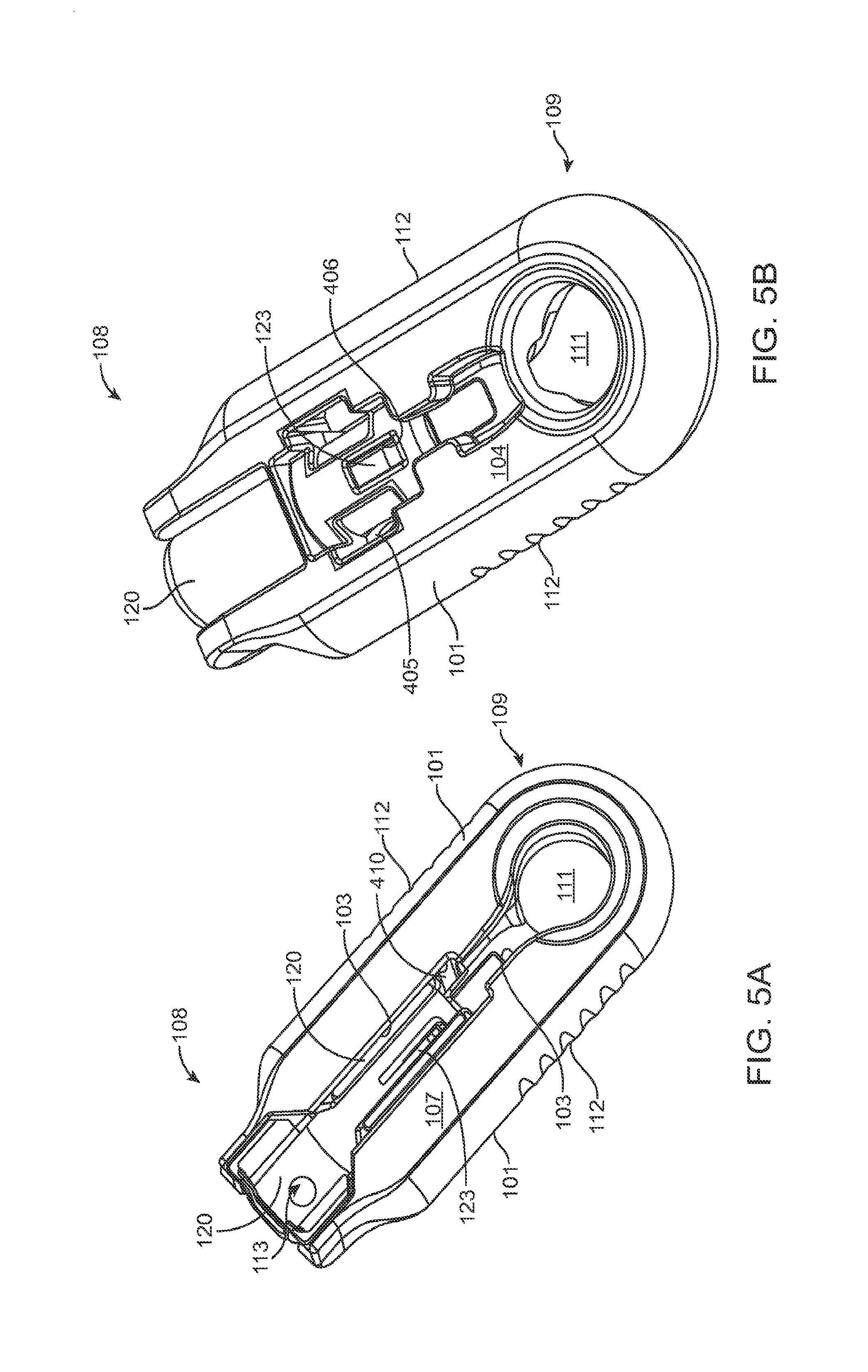
FIGS. 5A, 5B, and 5C show a front, back, and a proximal end view of the guide sleeve coupled to the shell;
FIG. 6 shows another implementation of a system with the fill syringe coupled to the carrier;
FIG. 7 shows the system of FIG. 1B after the syringe has been used to fill the implant with drug and removed from the carrier;
FIGS. 8A and 8B shows an example of a mechanism for locking a guide sleeve to a carrier member;
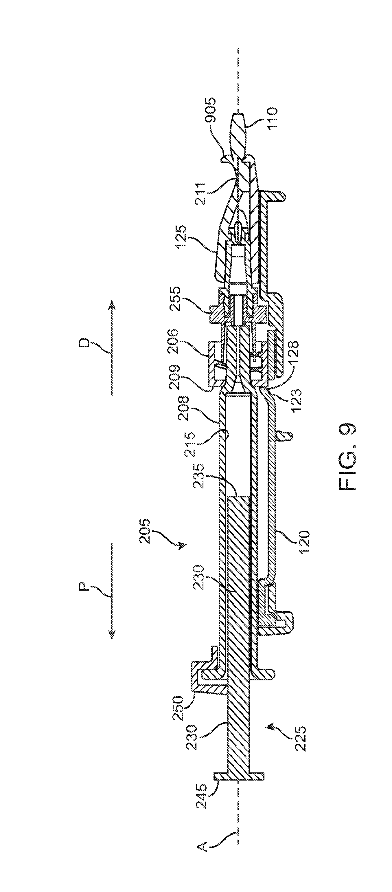
FIG. 9 shows a cross-sectional view of a locking mechanism that locks the guide sleeve to the carrier member;
FIG. 10A shows an implementation of an implant holder for use with the system;
FIG. 10B shows the implant holder of FIG. 10A holding an implant;
FIGS. 10C, 10D, and 10E are front, side and back views, respectively of the implant holder of FIG. 10B;
FIG. 10F is a partial cross-sectional view of the implant holder of FIG. 10B;
FIG. 10G is a detail view of FIG. 10F taken along circle G;
FIG. 11 shows a handle member of the system ready to be inserted into the carrier member;
FIG. 12 shows the handle member after it has been removed from the carrier member with the removable implant holder now attached to the handle member;
FIG. 13 shows a locking mechanism that initially secures the implant holder to the carrier member;
FIGS. 14A and 14B show the implant holder in a grasping state and a released state, respectively;
FIGS. 14C and 14D are partial views of the actuator system of the handle member;
FIGS. 15A and 15B are cross-sectional views of a mechanism for releasing the implant from the implant holder.
DETAILED DESCRIPTION
Described herein are methods, devices and systems for easily, reproducibly, and safely filling an ocular implant with a material, such as a drug, and inserting the implant into a patient, such as a patient's eye. Although specific reference is made to placement of devices in the eye, systems described herein can be used with many devices used in locations other than the eye, such as in orthopedic, dental, intraluminal and transdermal locations. The systems and methods described herein are well suited for use with many drug delivery devices, such as refillable diffusion based devices, and can be exceptionally well suited for diffusion devices having a porous drug release structure configured for extended release in which the porous structure inhibits flow of fluid during exchange.
FIG. 1A shows an implementation of a system for holding, filling, and/or delivering an ocular implant. The system 100 can include an ocular implant handling system including an implant carrier member 105 and a handle member 115. The system 100 can further include a fill syringe 205 (see FIG. 1B). The fill syringe 205 can contain a therapeutic agent, such as a pre-filled syringe. The carrier member 105 is sized and shaped to initially store an implant 110 prior to implantation of the implant 110 into the eye. The fill syringe 205 can interface with the carrier member 105 to fill the implant 110 with a flowable material, such as a liquid drug or therapeutic agent. The fill syringe 205 can interdigitate with the carrier member 105 holding the implant 110 and lock into a portion of the carrier member 105 (e.g. a guide sleeve), as will be described in more detail below. The therapeutic agent or agents suitable for use with the implant 110 can vary, for example, as described in U.S. Pat. No. 8,623,395, entitled "Implantable Therapeutic Device," which is incorporated here in its entirety. The therapeutic agent can include one or more of a variety of active ingredients of the therapeutic agent, a formulation of the therapeutic agent, a commercially available formulation of the therapeutic agent, a physician prepared formulation of therapeutic agent, a pharmacist prepared formulation of the therapeutic agent, or a commercially available formulation of therapeutic agent having an excipient. The therapeutic agent may be referred to with generic name or a trade name.
A portion of the carrier member 105 can guide and properly align a cannula or needle 210 of the syringe 205 with the fill port of the implant 110. The syringe 205 can interdigitate with this portion of the carrier member 105 and lock into it such that when the syringe 205 is removed, for example, after filling the implant 110 with the drug from the syringe 205, the syringe 205 and this portion of the carrier member 105 locked onto the syringe can be withdrawn together. As will be described in more detail below, once the fill syringe 205 is removed (e.g. after the implant 110 is filled with drug), the handle member 115 can be inserted into the carrier member 105 and used to remove the implant 110 from the carrier member 105. The handle member 115 and the carrier member 105 can interchangeably couple to the implant 110. The handle member 115 can be coupled to the carrier member 105 in a manner that attaches the implant 110 to the handle member 115 and detaches the implant 110 from the carrier member 105. The handle member 115 can then be used to position the implant 110 and insert the implant 110 into an eye. Each of these features will be described in more detail below. It should be appreciated that the implant 110 can be pre-filled and stored within the carrier member 105. Alternatively, the implant 110 can be stored within the carrier member 105 while empty and filled prior to implantation in the eye, such as using a pre-filled syringe. It should also be appreciated that the implant 110 can be filled after implantation in the eye.
Generally, the implant 110 to be used with the system 100 described herein can include an internal reservoir. The reservoir can be a rigid-walled reservoir having a fixed volume. Alternatively, one or more of the reservoir walls can be configured to expand such that the reservoir volume changes depending on a fill status of the implant 110. The implant 110 can include a proximal retention structure 305 and an indentation 307 or narrowed region that is sized smaller than the retention structure 305. The indentation 307 can also be sized smaller than a shoulder region extending distal to the indentation 307. The indentation 307 can be sized to fit in an elongate incision. The proximal retention structure 305 can include an access port having a penetrable region. For example, the proximal retention structure 305 can include or be covered by a penetrable barrier or septum structure such that the reservoir can be filled with a material. One or more outlets can be positioned in fluid communication with the reservoir of the implant 110 such that therapeutic agent in the reservoir can be delivered to the patient. The one or more outlets can incorporate a porous structure including one or more of many porous structures such as sintered material, openings in a non-permeable material, openings having a size and number to release therapeutic agent at an intended rate, a plurality of holes etched in a material, a semi-permeable membrane, or nano-channels, for example. It should be appreciated that the configuration of implant 110 that can used with the system 100 described herein can vary. The systems described herein can be used with or incorporate features of devices described in U.S. Pat. No. 8,399,006, entitled "Posterior Segment Drug Delivery"; U.S. Pat. No. 8,905,963, entitled "Injector Apparatus and Method for Drug Delivery;" and U.S. Publication No. 2015/0080846, entitled "Insertion and Removal Methods and Apparatus for Therapeutic Devices," the entire disclosures of which are incorporated herein by reference.
As best shown in FIGS. 2A-2B and also FIGS. 3A-3B, 4A-4B, and 5A-5C, the carrier member 105 can include a shell 101 and a guide sleeve 120. The guide sleeve 120 can be removably attached to the shell 101. The system 100 can also include an implant holder 125 configured to releaseably hold an ocular implant 110 within the shell 101. The implant holder 125 can be reversibly coupled to the shell 101 of the carrier member 105. As such that implant holder 125 can be an interchangeable element that can be coupled to the carrier member 105, for example prior to filling with a syringe 205, and can be released from the carrier member 105, for example after filling with a syringe 205 and prior to implantation in a patient using a delivery tool. Thus, the implant holder 125 can be interchangeably coupled with the carrier member and the delivery tool.
The shell 101 of the carrier member 105 can include a central channel 103 extending at least partially through an upper surface of a first side, such as its front side 107, from a proximal end 108 of the carrier member 105 towards a distal end region 109 of the carrier member 105 along a longitudinal axis. The central channel 103 can terminate at an opening or window 111 extending through a distal end region 109 of the shell 101. The implant 110 can be positioned by the implant holder 125 within the window 111. The shell 101 of the carrier member 105 can be generally ergonomically shaped such that a user can hold the carrier member 105 in one hand positioned around the underside of the carrier member 105. The central channel 103 can be available and readily visible on the front side 107 of the carrier member 105. The shell 101 of the carrier member 105 can include one or more textured regions 112 or indentations on its external surface to improve a user's grip on the carrier member 105 during use.
It should be appreciated that reference herein to terms such as "upper," "lower," "upwards," "downwards," "front," "back," "proximal," "distal" are used herein for orientation from one point of view of a user operating the systems described herein and are not intended to be limiting.
The implant 110 can have an elongate axis extending through a center of the implant 110 from the proximal-most end to the distal-most end of the implant 110. The system 100 (and/or each of the components of the system) can also have an elongate axis that is concentric with the elongate axis of the implant 110 forming a longitudinal axis A with which each of the components of the system 100 are substantially aligned. When the implant 110 is held by the implant holder 125 within the carrier member 105, the elongate axis of the implant 110 can be aligned substantially with the longitudinal axis A of the system and the syringe 205 can be inserted substantially along the longitudinal axis A such that the needle 211 penetrates an upper surface of the implant 110. It should be appreciated that the syringe 205 can interdigitate within the central channel 103 along the longitudinal axis A or, in other implementations, can be inserted at an angle to the longitudinal axis A.
As mentioned, the carrier member 105 can include the guide sleeve 120 that can be removably attached within at least a region of the slot of the shell 101. The guide sleeve 120 can define a proximal port 113 into the central channel 103 of the shell 101 that allows for access to the slot from a proximal end of the shell 101. The guide sleeve 120 can help to ensure proper alignment between the syringe 205 and the implant 110 such that a needle 211 of the syringe 205 inserts through a septum or fill port of the implant 110. The guide sleeve 120 can provide guiding alignment during insertion of the syringe 205 through the port 113 into the central channel 103 towards the implant 110 mounted within the implant holder 125 of the carrier member 105.
The configuration of the guide sleeve 120 can vary. The guide sleeve 120 can have a length such that it extends a distance between the proximal end 108 of the shell 101 or central channel 103 and a distal region of the central channel 103. The guide sleeve 120 can be relatively flush with a proximal end 108 of the shell 101 (see FIGS. 2A and 2B) or the guide sleeve 120 can extend a distance beyond the proximal end 108 of the shell 101, for example, as shown in FIG. 1A-1B. In this implementation, the guide sleeve 120 can incorporate a gripping element 121. The gripping element 121 of the guide sleeve 120 may have an ergonomic size and shape that facilitates it being grasped by a user, such as between the fingers of a user's hand as will be described in more detail below.
In some implementations, the guide sleeve 120 can have a generally cylindrical shape. The guide sleeve 120 can be a generally cylindrical element having an overall c-shaped cross section such that the underside or back side of the guide sleeve 120 is cylindrical and the front side of the guide sleeve 120 is slotted or discontinuous (see FIGS. 4A-4B and also FIG. 5C). In this implementation when the guide sleeve 120 is reversibly coupled with the shell 101 in the central channel 103, the cylindrical lower surface of the guide sleeve 120 can abut a lower portion 104 of the shell 101 and the discontinuous portion of the guide sleeve 120 can align with the upper surface of the front side 107 of the shell 101.
As mentioned above and as best shown in FIG. 1B and also in FIG. 9, the syringe 205 can have a body sized and shaped to be inserted into the central channel 103 of the shell 101 of the carrier member 105 via the port 113 such that a needle 211 of a needle assembly 210 of the syringe 205 can be inserted into the implant 110 mounted via the implant holder 125 on the carrier member 105. The syringe 205 can fill the implant 110 with a liquid drug or any other liquid prior to inserting the implant 110 into the eye. The syringe 205 can have any of a variety of configurations as known in the art. In some implementations, the syringe 205 can include a reservoir 215 that may be pre-filled with a fluid drug or any other fluid. The reservoir 215 can include a proximal opening configured to receive a mechanism for expelling the fluid from the reservoir 215 through a distal opening of the reservoir 215. The mechanism for expelling the fluid from the reservoir 215 can be a plunger 225 including a piston rod 230 terminating at a piston head 235. The piston head 235 can be configured to contact the liquid to be injected from the reservoir 215 and maintain a seal as the plunger 225 is displaced distally within the reservoir 215. A stop element can be incorporated that prevents withdrawal of the piston rod 230 or piston head 235 through the proximal opening. A proximal end of the syringe 205 can include a flange 245 that can aid in the advancement of the plunger 225 within the reservoir 215 as is known in the art. As the syringe 205 is used to inject material into the implant 110 using the plunger 225, a user can apply a force against an upper surface of the flange 245 (e.g. with the user's thumb) and apply a force against a lower surface of portion 250 (e.g. with a user's finger) therein applying a squeezing pressure to the syringe 205 engaged with the carrier member 105.
The distal opening of the reservoir 215 can be in fluid communication with a needle assembly 210 coupled to the syringe by a luer 255 (see FIG. 1B and FIG. 9). The needle assembly 210 can include a needle 211 and optionally a needle limiter 212 positioned around the needle 211. The needle limiter 212 can have a length such that a distal-most tip of the needle 211 extends only a short distance beyond the needle limiter 212 to prevent penetration of the needle 211 within the implant 110 beyond that short distance so as not to damage the implant 110 during filling. As the distal-most tip of the needle 211 penetrates the septum or fill port of the implant 110, the needle limiter 212 can abut an internal region of the implant holder 125 or an upper surface of the implant 110 preventing the needle 211 from penetrating the implant 110 beyond a desired depth. The syringe 205 can include a needle cap configured to cover the needle 211 and needle limiter 212. The needle assembly 210 may be integrally formed with the syringe 205 or the needle assembly 210 may be detachable from the syringe 205.
As mentioned above, the guide sleeve 120 can be removably attached from within the central channel 103 of the shell 101. The shell 101 and/or the guide sleeve 120 can include a locking mechanism that reversibly secures the guide sleeve 120 to the shell 101. The locking mechanism can be released, for example, upon insertion of the syringe 205 as will be described in more detail below. After the syringe 205 has been inserted into the guide sleeve 120 positioned within the central channel 103 of the shell 101 such as to inject drug into the implant 110, the locking mechanism between the guide sleeve 120 and the shell 101 can unlock. The guide sleeve 120 can release from the shell 101 and lock onto the syringe 205 such that both the guide sleeve 120 and the syringe 205 can be removed from the shell 101 upon withdrawal of the syringe 205 from the implant 110. The locking mechanism can simultaneously release the guide sleeve 120 from the shell 101 and lock the guide sleeve 120 onto a region of the syringe 205. When the syringe 205 is inserted into the guide sleeve 120, which can be in locked engagement with the shell 101 of the carrier member 105, the locking mechanism holding the guide sleeve 120 onto the syringe 205 can be activated or locked and the locking mechanism locking the guide sleeve 120 to the shell 101 can be deactivated or unlocked. The respective locking mechanisms can activate/deactivate in a simultaneous or step-wise manner. Once the switch in engagement occurs (i.e. locked engagement between the guide sleeve 120 and the shell 101 to an unlocked state and unlocked engagement of the syringe 205 and the guide sleeve 120 to a locked state), the syringe 205 can then be removed from the carrier member 105 with the guide sleeve 120 secured to the syringe 205. FIG. 6 shows an implementation of the system 100 with the syringe 205 inserted into the carrier 105. FIG. 7 shows an implementation of the system 100 after the syringe 205 has been used to fill the implant 110 and the syringe 205 has been decoupled from the carrier member 105. The guide sleeve 120 is shown detached from the carrier member 105 and is now attached to the syringe 205. It should be appreciated that unlocking or detaching the guide sleeve 120 from the carrier member 105 is not dependent upon filling the implant 110.
The locking mechanism between the shell 101 and the guide sleeve 120 can include one or more corresponding slots and tabs providing a fixed, but reversible coupling between the shell 101 and the guide sleeve 120. In one implementation and as best shown in FIGS. 3A-4B, 4A-4B, and 7, the guide sleeve 120 can include one or more slots 122 having a size and shape configured to accept tabs 405 of the shell 101 such that the tabs 405 reversibly insert through the slots 122 when the guide sleeve 120 is positioned within the central channel 103 of the shell 101. The slots 122 can be located on opposing sides of the guide sleeve 120. The guide sleeve 120 can also include one or more tabs 123 formed by a u-shaped slot 126 through a thickness of the guide sleeve 120. It should be appreciated that tabs 405 as well as tabs 123 can have a degree of flexibility such that they can move slightly with respect to the longitudinal axis A of the system to provide for reversible attachment between the guide sleeve 120 and the shell 101 as well as between the guide sleeve 120 and the syringe 205, which will be described in more detail below.
FIGS. 3A-3B, 4A-4B and also FIGS. 8A-8B show an implementation of a locking mechanism that initially locks the guide sleeve 120 to the shell 101 of the carrier member 105. The shell 101 can include one or more tabs 405 configured to insert through one or more corresponding slots 122 in the guide sleeve 120. In FIG. 8A, the tabs 405 are shown in a first state that locks the guide sleeve 120 to the shell 101 of the carrier member 105. The flexible tabs 405 can extend through the corresponding slots 122 in the guide sleeve 120 preventing withdrawal of the guide sleeve 120 in a proximal direction along arrow P. In the locked first state, an edge of the slot 122 can abut a distal edge of the tab 405. FIG. 8B shows a syringe 205 inserted distally into the guide sleeve 120 such that an outer surface of the needle assembly 210 of the syringe 205 presses against an inner surface of the flexible tabs 405 urging them in outward direction. The proximal end of the tabs 405 can be ramped such that the outer surface of the needle assembly 210 can smoothly press against and slide along the inner surface of the tabs 405 as the syringe 205 is urged in a distal direction along arrow D. The tabs 405 can be urged back out the slots 122 in the guide sleeve 120 releasing the locking engagement between the slots 122 of the guide sleeve 120 and the tabs 405 of the shell 101. In the unlocked second state, the edge 124 of the slot 122 may no longer abut the distal edge 408 of the tab 405.
This same act of inserting the syringe 205 distally through the guide sleeve 120 releasing the locked engagement between the guide sleeve 120 and the shell 101 can also cause the guide sleeve 120 to lock onto a portion of the syringe 205. In some implementations, the one or more tabs 123 formed by the u-shaped slot 126 through a thickness of the guide sleeve 120, for example, in the cylindrical underside of the guide sleeve 120 (see FIG. 4B and also FIG. 9). Similar to the tabs 405 of the shell 101, the tab 123 on the guide sleeve 120 can flex inward and outward relative to a longitudinal axis A of the guide sleeve 120 to capture a corresponding portion of the syringe 205. A free end 128 of the tab 123 can be angled or curved such that it projects inward towards the longitudinal axis of the guide sleeve 120, or have a feature that encroaches within the interior of the sleeve 120. When the syringe 205 is inserted distally through the guide sleeve 120 releasing the tabs 405 of the shell 101 from the slots 122 in the guide sleeve 120, the flexible tab 123 of the guide sleeve 120 can capture the corresponding portion of the syringe 205 preventing the syringe 205 from being detached from the carrier member 105 without the guide sleeve 120 being coupled to the syringe 205.
As mentioned previously, the guide sleeve 120 can include an inner diameter configured to receive the outer diameter of the syringe 205 such that the syringe 205 can be inserted through the guide sleeve 120 to inject drug into the implant 110 mounted within the implant holder 125 located distal to the guide sleeve 120 (see FIG. 9). The free end 128 of the flexible tab 123 of the guide sleeve 120 projecting inward towards the central longitudinal axis A of the system 100. The syringe 205 can urge the flexible tab 123 outward away from the central longitudinal axis A as the syringe 205 is inserted through the guide sleeve 120. Thus, the syringe 205 can be freely inserted in a distal direction along arrow D through the guide sleeve 120. However, the tab 123 can prevent the syringe 205 from being withdrawn in a proximal direction along arrow P away from the guide sleeve 120. As best shown in FIG. 9, a distal region of the syringe 205 can include a first portion 206 having a first outer diameter and a second portion 208 having a second outer diameter. The first portion 206 can be located distally to the second portion 208 and the first outer diameter can be larger than the second outer diameter. As the syringe 205 is inserted through the guide sleeve 120, the outer diameter of the first portion 206 can abut the free end 128 of the tab 123 urging the tab 123 outward. Once the first portion 206 is advanced distal to the tab 123, the free end 128 can flex back inward towards the longitudinal axis A and towards the smaller diameter second portion 208 located proximal to the first portion 206. The first portion 206 can have a proximal ledge 209 such that if the syringe 205 is withdrawn in a proximal direction, the free end 128 of the tab 123 can abut the proximal ledge 209 and cause the now-released guide sleeve 120 to withdraw along with the syringe 205.
As mentioned above, an implant holder 125 can be removably attached within at least a region of the central channel 103 of the shell 101. The implant holder 125 can be positioned such that an interior 901 of the implant holder 125 is coaxial with the central channel 103 of the carrier member 105 and the guide sleeve 120 (see FIG. 2A). A proximal end 902 of the implant holder 125 can lie adjacent to the distal end of the guide sleeve 120 and a distal end 903 of the implant holder 125 can extend beyond the central channel 103 into the window 111. The interior 901 of the implant holder 125 can be configured to receive at least a portion of the needle assembly 210 of the syringe 205 (see FIG. 6), as will be described in more detail below.
Now with respect to FIGS. 10A-10G, the implant holder 125 can include a pair of moveable mating graspers 905a, 905b configured to releasably secure the implant 110 to the carrier member 105. As best shown in FIGS. 10F and 10G, the implant 110 can include a proximal retention structure 305 that can include an indentation 307 dimensioned to receive first protrusion 907a of a first grasper 905a and a second protrusion 907b of a second grasper 905b to hold the implant 110 therebetween. The protrusions 907a, 907b can be shaped in a variety of ways to engage the implant 110, including lentoid, oval, elliptical, or circular structures. The protrusions 907a, 907b can include a structure similar to the shape profile or outer contour or corresponding geometry of the indentation of the implant 110.
Still with respect to FIGS. 10F-10G, first protrusion 907a on the first grasper 905a can include a proximal surface 910a to engage a region of the distal surface 306a of the retention structure 305, and the second protrusion 907b on the second grasper 905b can include a proximal surface 910b to engage another region of the distal surface 306b of the retention structure 305. The first grasper 905a can be urged toward the second grasper 905b to slide the first protrusion 907a and the second protrusion 907b into the indentation 307 of the retention structure 305 such that the proximal surfaces 910a, 910b engage the distal surfaces 306a, 306b. The graspers 905a, 905b can extend substantially around a portion of the retention structure 305 of the implant 110 to hold the implant 110. The septum or fill port of the implant 110 can be available within the interior 901 of the implant holder 125 and the body of the implant 110 can extend beyond the implant holder 125. The implant 110 can be held by the implant holder 125 such that a longitudinal axis of the implant 110 is aligned substantially concentric or coaxial with the longitudinal axis A of the system 100.
The syringe needle 211 can be inserted coaxially along the axis A of the implant 110 such that the needle 211 of the syringe 205 is advanced along the axis A toward the proximal end of the implant 110. The needle 211 of the syringe 205 can penetrate the fill port until a needle stop 212 contacts the proximal surface 910 of the graspers 905 or a proximal end of the implant 110 preventing further penetration of the needle 211. The interior 901 of the implant holder 125 as well as the guide sleeve 120 can further aid in aligning the syringe 205 and the needle 211 with the implant 110 and with the longitudinal axis A. The implant holder 125 can additionally incorporate an opening into the interior 901 such that a needle can be inserted at an angle to the longitudinal axis A.
The implant holder 125 can be an interchangeable element that can lock in an alternating fashion with different portions of the system 100, such as the shell 101 of the carrier 105 and a portion of the handle member 115. The proximal end 902 of the implant holder 125 can be reversibly coupled to a region of the shell 101 such as within the central channel 103 by a locking mechanism. The locking mechanism can be configured to unlock the implant holder 125 from the shell 101 and then lock the implant holder 125 onto the handle member 115 once the handle member 115 is inserted into the carrier member 105, which is described in more detail below. The implant holder 125 can be attached to the region of the shell 101 and then attached to the handle member 115 upon release from the shell 101. The locking mechanism can include an indentation 912 near a proximal end 902 of the implant holder 125 configured to receive a correspondingly shaped element 410 of the shell 101 (see FIG. 3A and also FIG. 13). The indentation 912 can have smooth edges such that the implant holder 125 can be removed from the element 410, as will be described in more detail below. The locking mechanism can also include a tab 914 formed by a u-shaped slot 916 located adjacent the indentation 912, such as just distal to the indentation 912. The tab 914 can include a projection 918 on its inner surface (see FIG. 10F) configured to engage with a correspondingly shaped recess 505 within a region of the handle member 115 when the handle member 115 is inserted through the interior 901 of the implant holder 125 as will be described in more detail below.
As mentioned above, the system 100 can also include the handle member 115. After the syringe 205 is removed from the carrier 105 and the guide sleeve 120 has transferred attachment from the shell 101 of the carrier 105 to the syringe 205 as shown in FIG. 7, the handle member 115 can be attached to the implant holder 125 holding the implant 110 (see FIGS. 11 and 12). The implant holder 125 can be interchangeably attached to the shell 101 of the carrier 105 and the handle member 115. Insertion of the handle member 115 into the carrier member 105 can release the attachment of the implant holder 125 with the shell 101 and cause the attachment between the implant holder 125 and the handle member 115 such that the implant holder 125 can be removed from the carrier 105 and the handle member 115 can be used to insert the implant being held by the implant holder 125 into a patient.
The handle member 115 can include an elongated proximal portion 510 that can be grasped by a user and the distal attachment portion 130 that can releaseably attached to the implant 110 via the implant holder 125. The proximal portion 510 of the handle member 115 can be sized and shaped to be grasped by a user and can have an ergonomic shape that facilitates quick and easy positioning of the implant 110 and release of the implant 110 into the patient. The distal attachment portion 130 of the handle member 115 can be inserted into the central channel 103 of the carrier member 105 after removal of the guide sleeve 120 from the central channel 103. In this regard, the attachment portion 130 can removably attach, engage or otherwise mate with the implant holder 125 of the carrier member 105, which holds the implant 110 (see FIG. 11). Once attached to the implant holder 125, the handle member 115 can be removed from the carrier member 105 such that it takes the implant holder 125 (and attached implant 110) out of the carrier member 105 along with it. The handle member 115 can then be used to manipulate the implant 110 held by the implant holder 125 such that the implant 110 can be inserted into an eye. FIG. 12 shows handle member 115 after it has been removed from the carrier member 105 with the removable implant holder 125 now attached to the handle member 115.
As described above and with respect to FIG. 13, the proximal end 902 of the implant holder 125 can be reversibly coupled to a region of the shell 101 by a locking mechanism configured to unlock the implant holder 125 from the shell 101 and lock the implant holder 125 onto the handle member 115 once the handle member 115 is inserted into the carrier member 105. The locking mechanism can include the indentation 912 located near a proximal end 910 of each grasper 905 and the tab 914 adjacent the indentation 912 having the projection 918 on its inner surface. The projection 918 can have a ramped proximal end and a flat lower surface 920. When the implant holder 125 is locked to the shell 101, the correspondingly-shaped element 410 of the shell 101 can rest within the indentation 912. When the attachment portion 130 of the handle 115 is inserted through the implant holder 125, the projection 918 on the inner surface of the tab 914 can insert within the recess 505 near the distal end of the attachment portion 130. Distal movement of the attachment portion 130 along arrow D through the interior 901 of the implant holder 125 can cause the tab 914 to flex slightly outward as the outer surface of the distal end of the attachment portion 130 slides past the ramped surface of the projection 918 on the inner surface of the tab 914. Once the projection 918 aligns with the recess 505, the tab 914 can flex back inward such that the projection 918 snaps into the recess 505. The recess 505 and the projection 918 can have corresponding shapes such that the projection 918 can be received at least in part within the recess 505. Further distal movement of the handle 115 through the interior 901 of the implant holder 125 can be prevented due to contact between the distal-most end of the attachment portion 130 and a surface 925 of the interior 901 of the implant holder 125. Thus, a region of the attachment portion 130 between the recess 505 and the distal-most end of the attachment portion 130 can be captured between the projection 918 and this surface 925 (see FIG. 13). Proximal withdrawal of the handle 115 along arrow P from the central channel 103 of the shell 101 can cause a lower surface 920 of the projection 918 to abut a distal wall 515 of the recess 505 causing the implant holder 125 to be withdrawn with the handle 115 in a proximal direction along arrow P out from the central channel 103.
Now with regard to FIGS. 14A-14D, the handle member 115 can have at least one deployment mechanism including an actuator 705, such as a button, knob, slider, etc., that can be actuated to detach the implant 110 from the implant holder 125 and handle member 115. The actuation of the actuator 705 can simply release the implant 110 or it can push or otherwise expel the implant 110 from the handle member 115. FIGS. 14A and 14B shows an implementation of a deployment mechanism that releases the implant 110 from the handle member 115 upon actuation of the actuator 705. As described above, the implant holder 125 can include a pair of movable tips or graspers 905 that grasp the implant 110 such that when the handle member 115 is inserted within the interior 901 of the implant holder 125 the graspers 905 secure the implant 110 to the handle member 115. In the initial state shown in FIG. 14A, the graspers 905 can be positioned such that they hold the implant 110 in a secured position relative to the handle member 115. Once the actuator 705 is depressed, the graspers 905 can separate and release the implant 110 as shown in FIG. 14B. FIG. 15A-15B show cross-sectional views of an implementation of the deployment mechanism. The actuator 705 can be pressed (or slide) so as to exert a force onto a spring held slider member 1005. The force of the actuator 705 can slide the slide member 1005 to a position that causes the graspers 905 to open. The amount of force required to slide the slider member 1005 forward and open the graspers 905 can be variable. The slider member 1005 and the actuator interface at ramped connection can have different ramp angles resulting in a smoothing of the force required for the user to open the handle tips.
In an implementation, the actuator 705 can include an actuator element 701 configured to pivot around a pivot pin 710 when the actuator 705 is depressed towards an upper surface 520 of the handle member 115. The actuator element 701 can also include a projection 715 extending from its lower surface 720 such that as the element 701 pivots around the pivot pin 710 the projection 715 is moved downwards such that the ramped surface 725 of the projection 715 slides along a ramped surface 1010 of the slider member 1005. This contact between the ramped surface 725 of the projection 715 against the ramped surface 1010 of the slider member 1005 can cause the slider member 1005 to move in a proximal direction against the force of the spring 730 compressing the spring 730. The slider member 1005 can have a forked region 1015 near its distal end. The attachment portion 130 of the handle member 115 can interface with the forked region 1015. The attachment portion 130 can include a first arm 525 rotatably coupled to a second arm 530 around a pivot point 535. The first arm 525 and second arm 530 can be biased such as by a spring or other element such that their distal ends 540 are urged towards one another. As described above, the distal region 540 of the arms 525, 530 can extend within the interior 901 of the implant holder 125 such that the projections 918 of the implant holder 125 mate with the recesses 505 on the arms 525, 530. A region 545 of the arms 525, 530 proximal of the pivot point 535 can interface with the forked region 1015 of the slider member 1005. A first prong 1020a of the forked region 1015 can rest against a first region 550 of the arm 525 and a second prong 1020b of the forked region 1015 can rest against a second region 550 of the arm 530 (see FIG. 14A). When the slider member 1005 is moved in a proximal direction along arrow P, the first and second prongs 1020a, 1020b can slide relative to the arms 525, 530 such that they abut a ramped proximal end 545 of each respective arm 525, 530 and cause the arms 525, 530 to open or pivot relative to one another around pivot point 535. The distal region 540 of the arms 525, 530 can move away from one another in a scissor-like movement. This, in turn, can cause the distal region 540 of the arms 525, 530 engaged with the projections 918 of the implant holder 125 to press against the inner surface of the implant holder 125 and can cause the graspers 905 to likewise move away from one another releasing the implant 110 held therebetween (see FIG. 14B).
The actuator element 701 can be arranged relative to the arms 525, 530 of the handle member 115 such that as the actuator element 701 is pressed downwards towards the upper surface of the handle member 115, the arms 525, 530 can each move outward at an angle away from the longitudinal axis A of the system 100 and from one another. The arms 525, 530 can be configured to move away from one another such that one arm moves to a first side and the opposing arm moves to a second opposite side away from the longitudinal axis A of the system 100. The arms 525, 530 also can be configured to move away from one another such that one arm moves upwards and one arm moves downwards away from the longitudinal axis A of the system 100. As mentioned previously, reference herein to terms such as "upper," "lower," "upwards," "downwards," "front," "back," "proximal," "distal" etc. are used herein for orientation from one point of view of a user operating the systems described herein and are not intended to be limiting. For example, the actuator element 701 can be positioned on an upper surface of the handle member 115 from the point of view of the user such that the actuator element 701 is pressed using a thumb and the actuator element 701 moved towards the upper surface of the handle member 115. The actuator element 701 also can be positioned on a lower surface of the handle member 115 from the point of view of the user such that the actuator element 701 is pressed using a finger and the actuator element 701 moved towards the lower surface of the handle member 115.
One or more components of the system 100 can be provided as a kit. The kit can include sterile packaging within which one or more components of the system 100 can be contained including the carrier member 105 having a guide sleeve 120 and implant holder 125 attached. An implant 110 can be held within the implant holder 125 or the implant 110 can be contained within sterile packaging separated from the system 100 such that the implant 110 is engaged with the implant holder 125 after the sterile kit has been opened. The kit can further include a handle member 115. The kit can further include needle assembly 210 configured to couple to a pre-filled syringe. Alternatively, the kit can include the syringe. The kit can further include a removal tool. In some implementations, the kit can include a carrier member 105 having a guide sleeve 120 and having an implant holder 125 coupled to the shell 101 of the carrier member 105. The implant holder 125 can be reversibly coupled to an implant 110. The implant 110 can be empty. In an interrelated implementation, the kit can further include a handle member 115 configured to engage with the implant holder 125 holding the implant 110 after the implant 110 has been filed with a drug. In an interrelated implementation, a syringe 205 can be provided that is configured to interdigitate with a portion of a carrier member 105 such that a needle of the syringe 205 can insert through a proximal portion of the implant 110 being held by the carrier member 105 to fill the implant 110 with a drug. The syringe 205 can be pre-filled with one or more therapeutic agents. The carrier member 105 can include a guide sleeve 120 configured to lock onto a portion of the syringe 205 upon insertion of the syringe 205 into the guide sleeve 120 of the carrier member 105. The implant 110 can be held by an implant holder 125 locked onto the carrier member 105, such as within the central channel 103. The implant holder 125 holding the implant 110 can attach to a portion of a handle member 115 after removal of the syringe 205 from the carrier member 105 upon filling of the implant 110. The handle member 115 having the implant holder 125 now attached to it can be used to deliver the implant 110 held within the implant holder 125 into a target location of the patient. In an interrelated implementation, the kit can include a carrier member 105 having a shell 101 and a guide sleeve 120, and an implant holder 125 holding an implant 110. The carrier member 105 can have a central channel 103 that facilitates access to the implant 110 being held by the implant holder 125, such as for filling with a syringe 205. The syringe 205 can be part of the kit or a separate component. The syringe 205 can be pre-filled with one or more therapeutic agents or can be empty. The handle member 115 can also be part of the kit or a separate component. The implant 110 can be part of the kit or a separate component. In an interrelated aspect, all of the components can be provided as a single kit or can be provided as separate components.
While this specification contains many specifics, these should not be construed as limitations on the scope of what is claimed or of what may be claimed, but rather as descriptions of features specific to particular embodiments. Certain features that are described in this specification in the context of separate embodiments can also be implemented in combination in a single embodiment. Conversely, various features that are described in the context of a single embodiment can also be implemented in multiple embodiments separately or in any suitable sub-combination. Moreover, although features may be described above as acting in certain combinations and even initially claimed as such, one or more features from a claimed combination can in some cases be excised from the combination, and the claimed combination may be directed to a sub-combination or a variation of a sub-combination. Similarly, while operations are depicted in the drawings in a particular order, this should not be understood as requiring that such operations be performed in the particular order shown or in sequential order, or that all illustrated operations be performed, to achieve desirable results. Only a few examples and implementations are disclosed. Variations, modifications and enhancements to the described examples and implementations and other implementations may be made based on what is disclosed.
In the descriptions above and in the claims, phrases such as "at least one of" or "one or more of" may occur followed by a conjunctive list of elements or features. The term "and/or" may also occur in a list of two or more elements or features. Unless otherwise implicitly or explicitly contradicted by the context in which it is used, such a phrase is intended to mean any of the listed elements or features individually or any of the recited elements or features in combination with any of the other recited elements or features. For example, the phrases "at least one of A and B;" "one or more of A and B;" and "A and/or B" are each intended to mean "A alone, B alone, or A and B together." A similar interpretation is also intended for lists including three or more items. For example, the phrases "at least one of A, B, and C;" "one or more of A, B, and C;" and "A, B, and/or C" are each intended to mean "A alone, B alone, C alone, A and B together, A and C together, B and C together, or A and B and C together."
Use of the term "based on," above and in the claims is intended to mean, "based at least in part on," such that an unrecited feature or element is also permissible.
* * * * *
References
-
ema.europa.eu/docs/en_GB/document_library/EPAR_-_Scientific_Discussion/human/000715/WC500043550.pdf
-
iovs.org/cgi/reprint/46/2/726
-
pmiapp.com/publications/docs/A_Novel_technique_for_surface_area.pdf
-
-
mpif.org/DesignCenter/porous.pdf
-
afssociety.org/education/0907oneminute.htm
-
-
revophth.com/archive/newsletter/0206_retina.htm
-
retinalphysician.com/article.aspx?article=101096
D00000
D00001
D00002
D00003
D00004
D00005
D00006
D00007
D00008
D00009
D00010
D00011
D00012

D00013
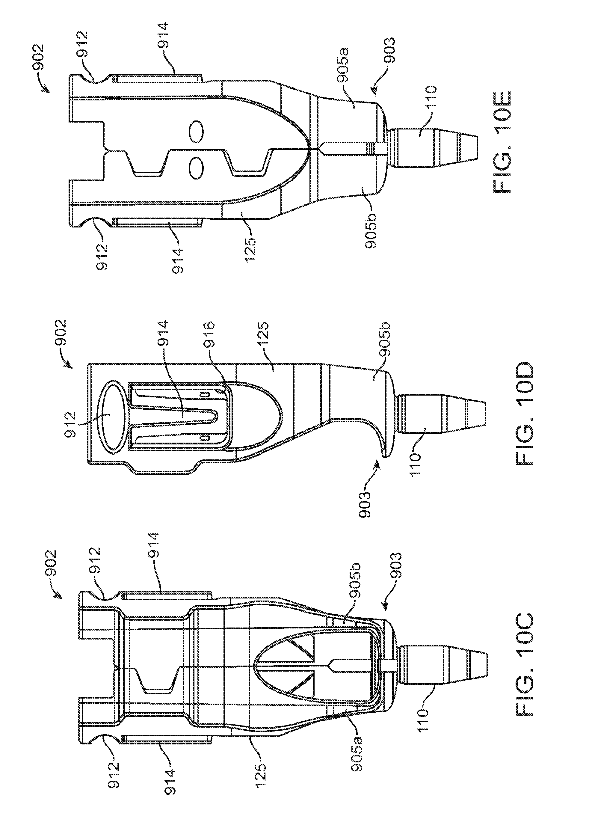
D00014
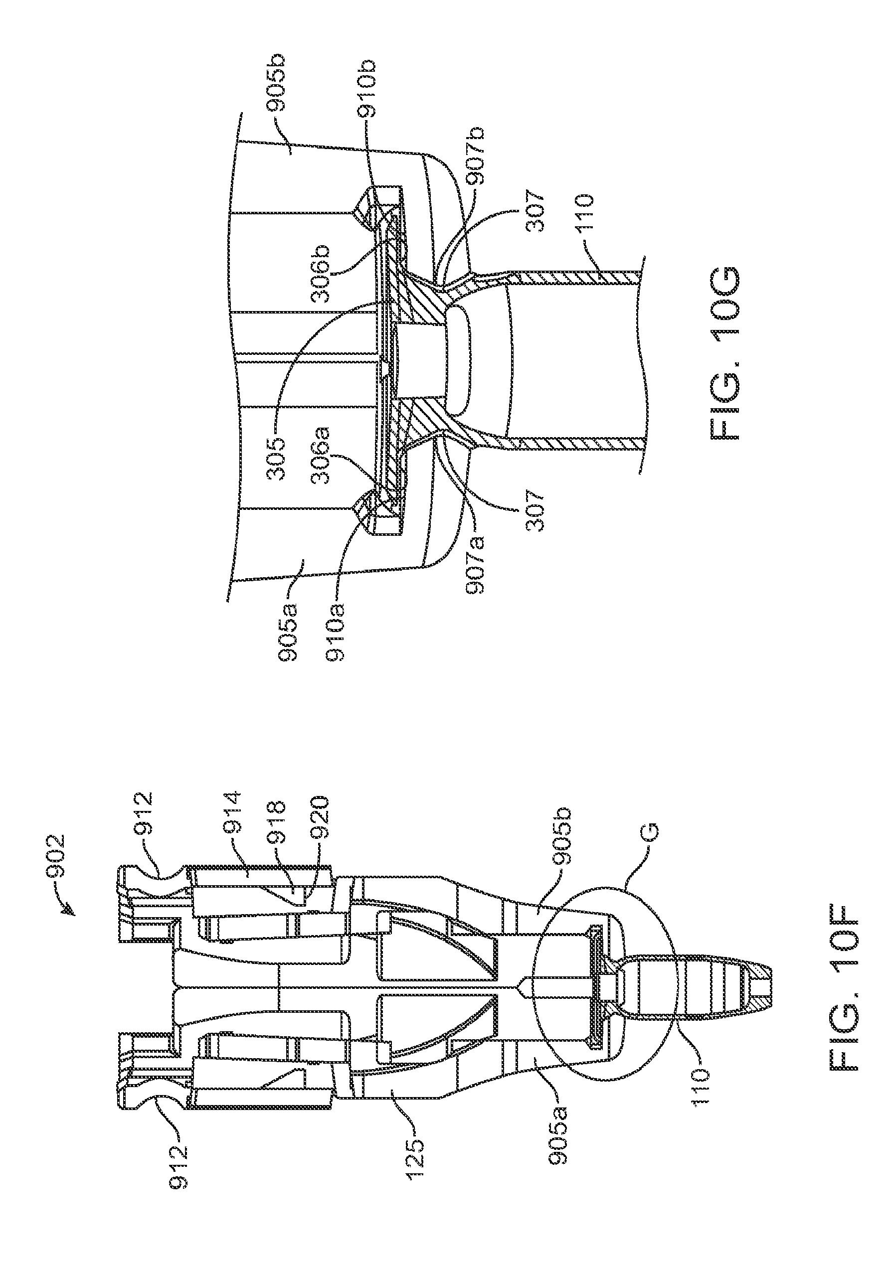
D00015
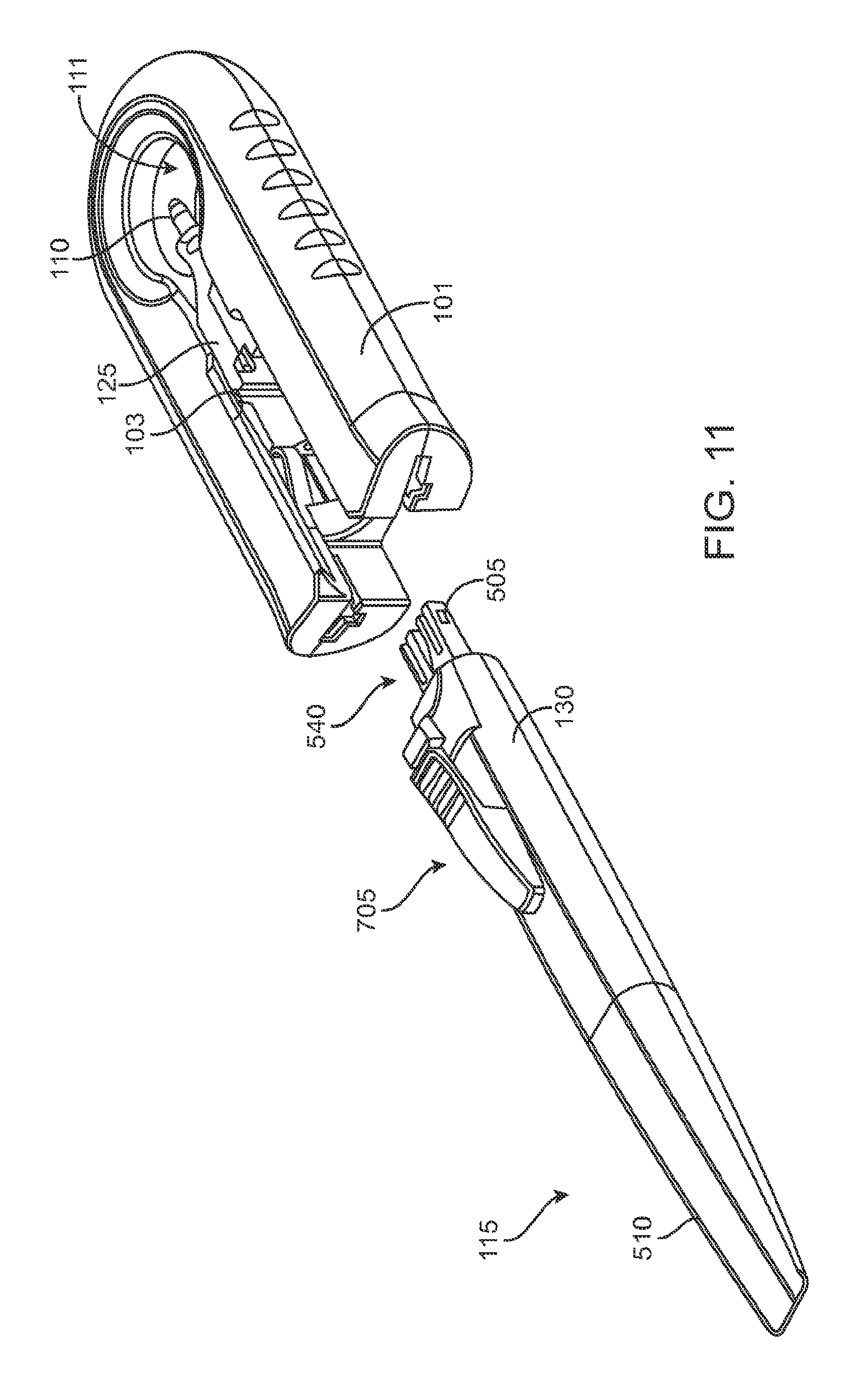
D00016
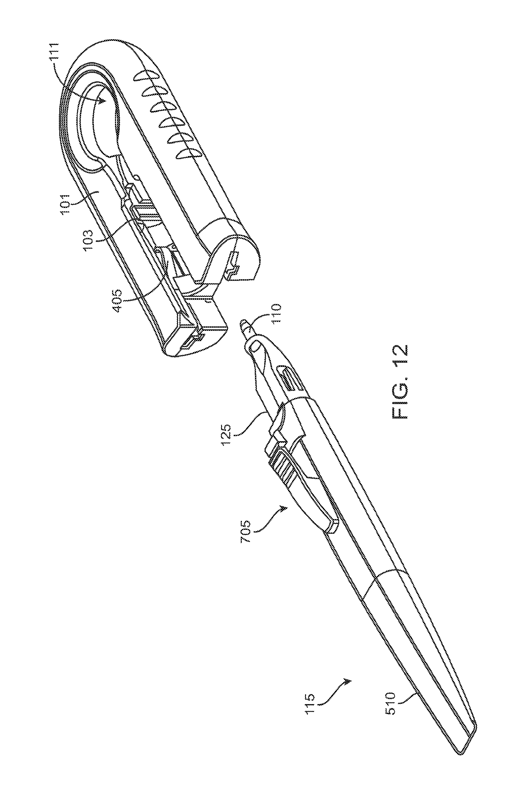
D00017
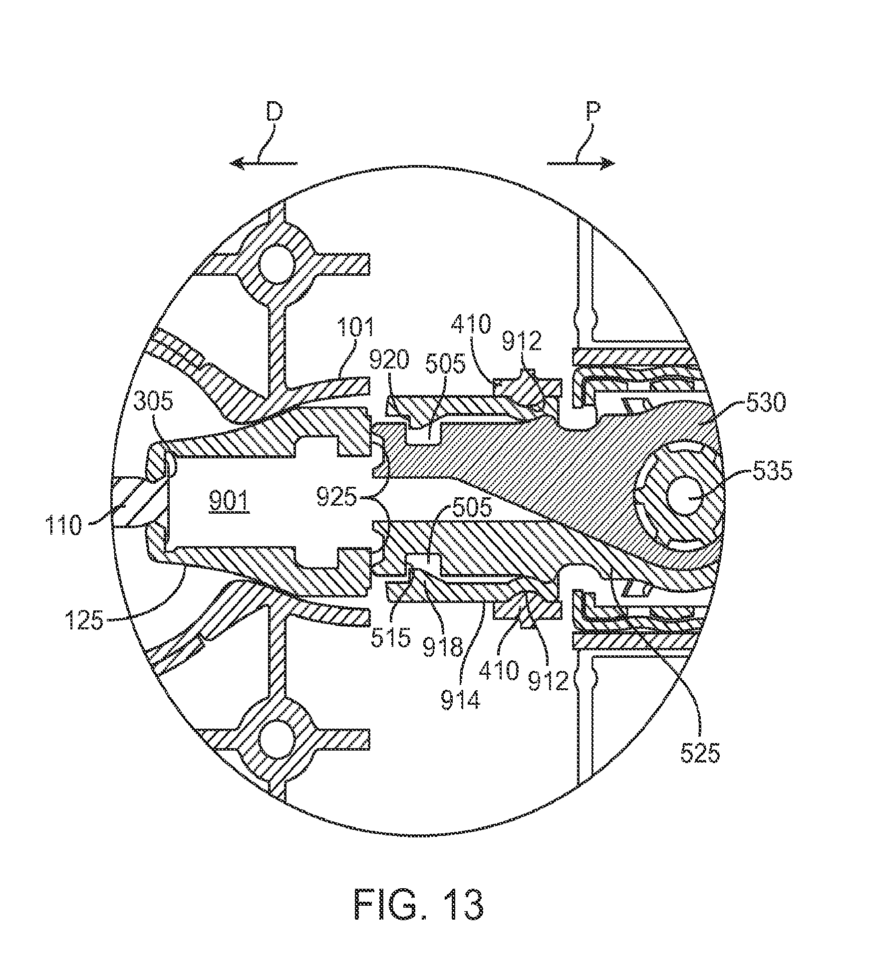
D00018

D00019

D00020
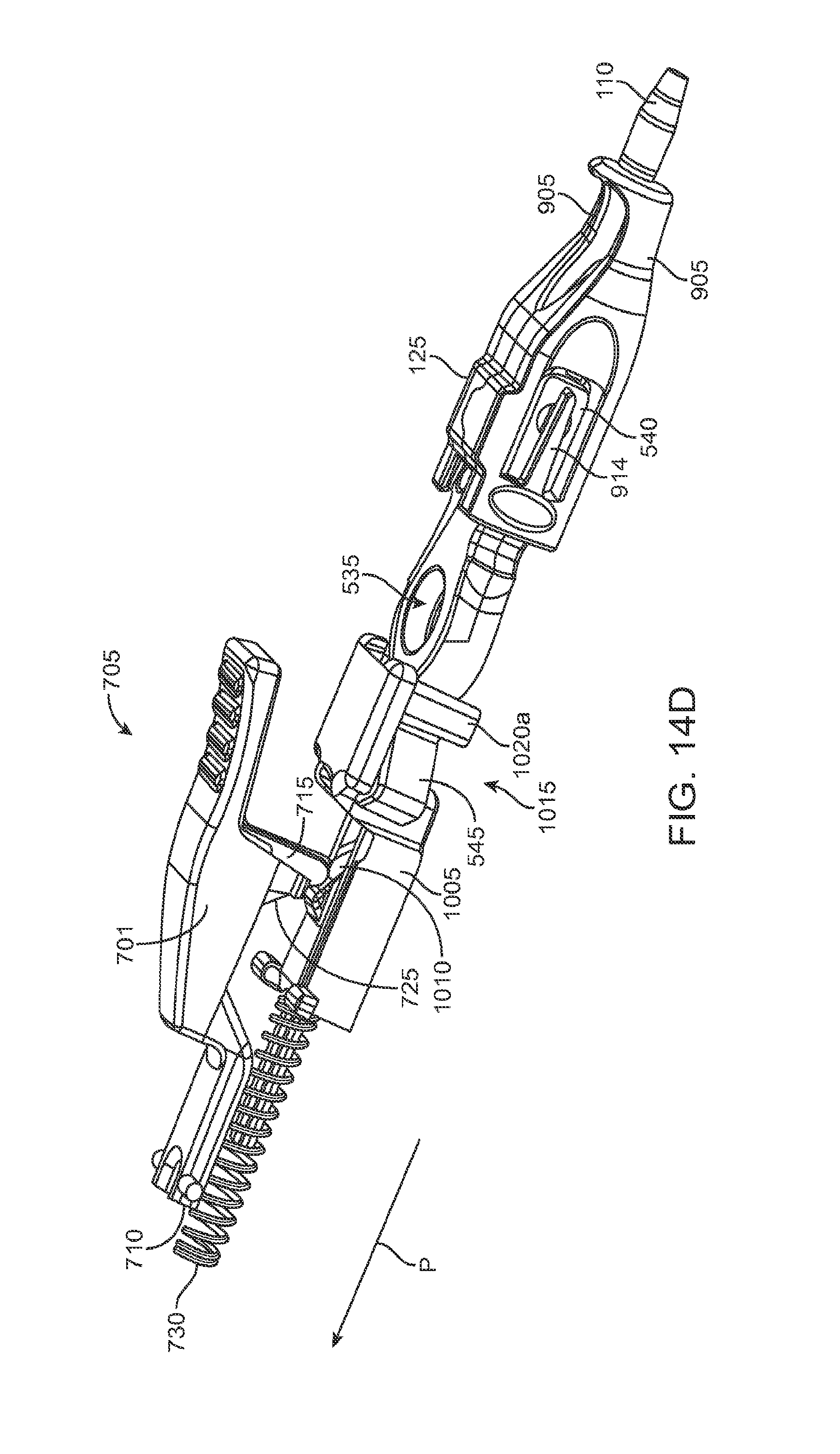
D00021
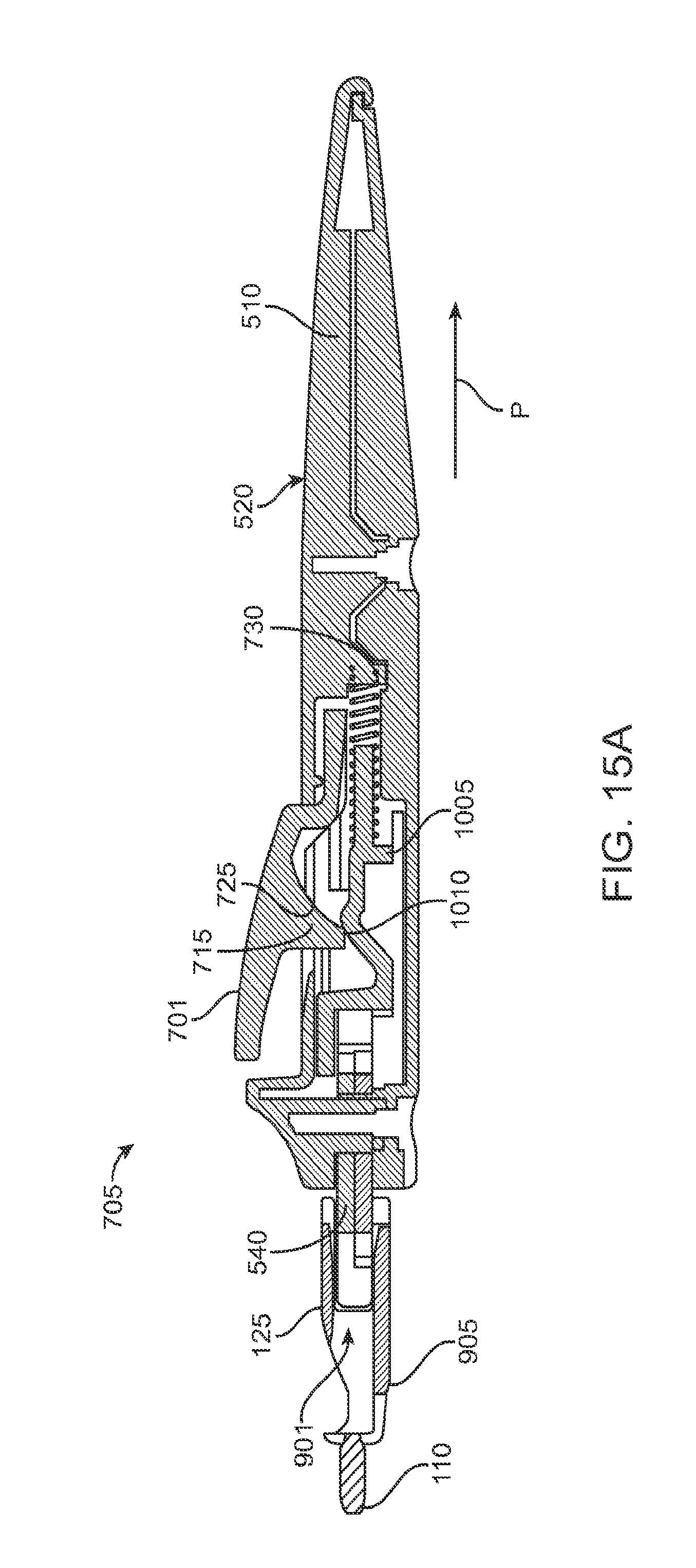
D00022
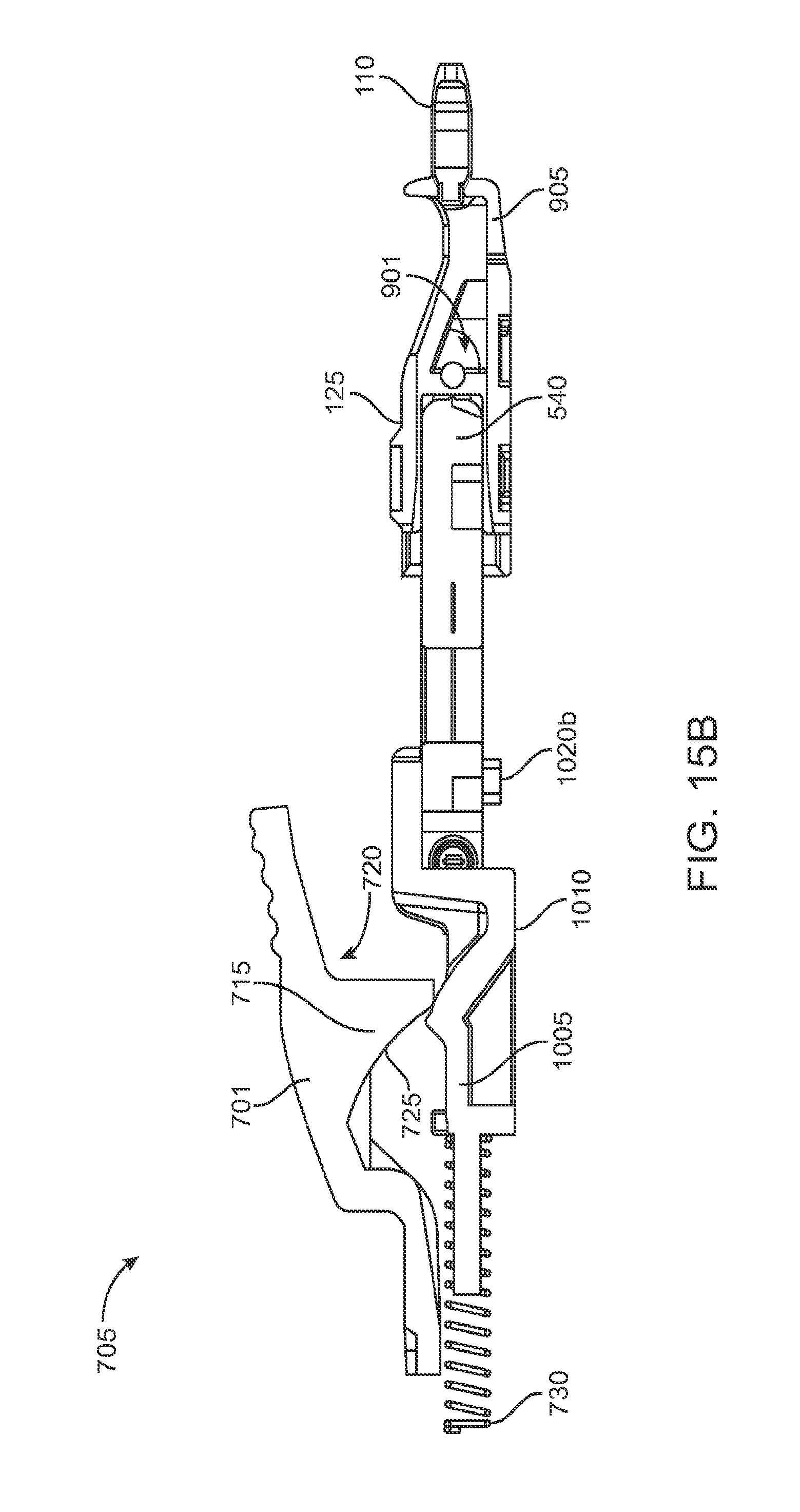
XML
uspto.report is an independent third-party trademark research tool that is not affiliated, endorsed, or sponsored by the United States Patent and Trademark Office (USPTO) or any other governmental organization. The information provided by uspto.report is based on publicly available data at the time of writing and is intended for informational purposes only.
While we strive to provide accurate and up-to-date information, we do not guarantee the accuracy, completeness, reliability, or suitability of the information displayed on this site. The use of this site is at your own risk. Any reliance you place on such information is therefore strictly at your own risk.
All official trademark data, including owner information, should be verified by visiting the official USPTO website at www.uspto.gov. This site is not intended to replace professional legal advice and should not be used as a substitute for consulting with a legal professional who is knowledgeable about trademark law.