Autonomous drive user interface
Jubner , et al.
U.S. patent number 10,254,943 [Application Number 15/647,693] was granted by the patent office on 2019-04-09 for autonomous drive user interface. This patent grant is currently assigned to Neonode Inc.. The grantee listed for this patent is Neonode Inc.. Invention is credited to Thomas Eriksson, Simon Fellin, Gunnar Martin Frojdh, Stefan Holmgren, Alexander Jubner.


View All Diagrams
| United States Patent | 10,254,943 |
| Jubner , et al. | April 9, 2019 |
Autonomous drive user interface
Abstract
A user interface for a vehicle, including a steering wheel for the vehicle, including a grip, a sensor operable to detect objects at a plurality of locations along the grip, and an illuminator operable to illuminate different portions of the grip, a processor in communication with the sensor, with the illuminator and with a controller of vehicle functions, and a non-transitory computer readable medium storing instructions which cause the processor to identify, via the sensor, a location of a first object along the grip, to illuminate, via the illuminator, a portion of the grip, adjacent to the identified location, to further identify, via the sensor, a second object being at the illuminated portion of the grip, and to activate, via the controller, a vehicle function in response to the second object being at the illuminated portion of the grip.
| Inventors: | Jubner; Alexander (Spanga, SE), Eriksson; Thomas (Stockholm, SE), Frojdh; Gunnar Martin (Dalaro, SE), Fellin; Simon (Sigtuna, SE), Holmgren; Stefan (Sollentuna, SE) | ||||||||||
|---|---|---|---|---|---|---|---|---|---|---|---|
| Applicant: |
|
||||||||||
| Assignee: | Neonode Inc. (San Jose,
CA) |
||||||||||
| Family ID: | 53006692 | ||||||||||
| Appl. No.: | 15/647,693 | ||||||||||
| Filed: | July 12, 2017 |
Prior Publication Data
| Document Identifier | Publication Date | |
|---|---|---|
| US 20170308281 A1 | Oct 26, 2017 | |
Related U.S. Patent Documents
| Application Number | Filing Date | Patent Number | Issue Date | ||
|---|---|---|---|---|---|
| 14805445 | Jul 21, 2015 | 9710144 | |||
| 14590010 | Jul 28, 2015 | 9092093 | |||
| 14551096 | Jul 12, 2016 | 9389710 | |||
| 14555731 | Nov 28, 2014 | 9741184 | |||
| 14312711 | Dec 23, 2014 | 8918252 | |||
| 14088458 | Jul 8, 2014 | 8775023 | |||
| 14312787 | Oct 20, 2015 | 9164625 | |||
| 14311366 | Jun 23, 2015 | 9063614 | |||
| 14140635 | Apr 7, 2015 | 9001087 | |||
| PCT/US2014/040112 | May 30, 2014 | ||||
| PCT/US2014/040579 | Jun 3, 2014 | ||||
| 61730139 | Nov 27, 2012 | ||||
| 61828713 | May 30, 2013 | ||||
| 61838296 | Jun 23, 2013 | ||||
| 61846089 | Jul 15, 2013 | ||||
| 61929992 | Jan 22, 2014 | ||||
| 61972435 | Mar 31, 2014 | ||||
| 61986341 | Apr 30, 2014 | ||||
| 61830671 | Jun 4, 2013 | ||||
| 61833161 | Jun 10, 2013 | ||||
| 61911915 | Dec 4, 2013 | ||||
| 61919759 | Dec 22, 2013 | ||||
| 61923775 | Jan 6, 2014 | ||||
| 61950868 | Mar 11, 2014 | ||||
| Current U.S. Class: | 1/1 |
| Current CPC Class: | B62D 1/046 (20130101); G06F 3/0421 (20130101); G06F 3/04847 (20130101); G06F 3/0488 (20130101); G06F 3/0416 (20130101); G06F 3/017 (20130101); B62D 1/04 (20130101); B60K 37/06 (20130101); G06F 3/04883 (20130101); G06F 3/04842 (20130101); B60K 2370/141 (20190501); G06F 3/033 (20130101); G06F 2203/0339 (20130101); G06F 3/0487 (20130101); B60K 2370/782 (20190501); H04M 2250/22 (20130101); B60K 2370/1446 (20190501) |
| Current International Class: | G06F 3/0484 (20130101); G06F 3/042 (20060101); B60K 37/06 (20060101); B62D 1/04 (20060101); G06F 3/0488 (20130101); G06F 3/041 (20060101); G06F 3/01 (20060101); G06F 3/033 (20130101); G06F 3/0487 (20130101) |
| Field of Search: | ;701/36 |
References Cited [Referenced By]
U.S. Patent Documents
| 4243879 | January 1981 | Carroll et al. |
| 4267443 | May 1981 | Carroll et al. |
| 4301447 | November 1981 | Funk et al. |
| 4518249 | May 1985 | Murata et al. |
| 4550250 | October 1985 | Mueller et al. |
| 4703316 | October 1987 | Sherbeck |
| 4710760 | December 1987 | Kasday |
| 4782328 | November 1988 | Denlinger |
| 4790028 | December 1988 | Ramage |
| 4847606 | July 1989 | Beiswenger |
| 4880969 | November 1989 | Lawrie |
| 4928094 | May 1990 | Smith |
| 5003505 | March 1991 | McClelland |
| 5016008 | May 1991 | Gruaz et al. |
| 5036187 | July 1991 | Yoshida et al. |
| 5053758 | October 1991 | Cornett et al. |
| 5103085 | April 1992 | Zimmerman |
| 5119079 | June 1992 | Hube et al. |
| 5162783 | November 1992 | Moreno |
| 5179369 | January 1993 | Person et al. |
| 5194863 | March 1993 | Barker et al. |
| 5220409 | June 1993 | Bures |
| 5283558 | February 1994 | Chan |
| 5406307 | April 1995 | Hirayama et al. |
| 5414413 | May 1995 | Tamaru et al. |
| 5422494 | June 1995 | West et al. |
| 5463725 | October 1995 | Henckel et al. |
| 5559727 | September 1996 | Deley et al. |
| 5577733 | November 1996 | Downing |
| 5579035 | November 1996 | Beiswenger |
| 5603053 | February 1997 | Gough et al. |
| 5612719 | March 1997 | Beemink et al. |
| 5618232 | April 1997 | Martin |
| 5729250 | March 1998 | Bishop et al. |
| 5748185 | May 1998 | Stephan et al. |
| 5785439 | July 1998 | Bowen |
| 5825352 | October 1998 | Bisset et al. |
| 5838308 | November 1998 | Knapp et al. |
| 5880743 | March 1999 | Moran et al. |
| 5886697 | March 1999 | Naughton et al. |
| 5889236 | March 1999 | Gillespie et al. |
| 5900875 | May 1999 | Haitani et al. |
| 5914709 | June 1999 | Graham et al. |
| 5936615 | August 1999 | Waters |
| 5943043 | August 1999 | Furuhata et al. |
| 5943044 | August 1999 | Martinelli et al. |
| 5956030 | September 1999 | Conrad et al. |
| 5988645 | November 1999 | Downing |
| 6010061 | January 2000 | Howell |
| 6023265 | February 2000 | Lee |
| 6031989 | February 2000 | Cordell |
| 6052279 | April 2000 | Friend et al. |
| 6073036 | June 2000 | Heikkinen et al. |
| 6085204 | July 2000 | Chijiwa et al. |
| 6091405 | July 2000 | Lowe et al. |
| 6114949 | September 2000 | Schmitz et al. |
| 6135494 | October 2000 | Lotito et al. |
| 6246395 | June 2001 | Goyins et al. |
| 6259436 | July 2001 | Moon et al. |
| 6292179 | September 2001 | Lee |
| 6310609 | October 2001 | Morgenthaler |
| 6323846 | November 2001 | Westerman et al. |
| 6340979 | January 2002 | Beaton et al. |
| 6346935 | February 2002 | Nakajima et al. |
| 6356287 | March 2002 | Ruberry et al. |
| 6359632 | March 2002 | Easily et al. |
| 6362468 | March 2002 | Murakami et al. |
| 6411283 | June 2002 | Murphy |
| 6421042 | July 2002 | Omura et al. |
| 6429857 | August 2002 | Masters et al. |
| 6456952 | September 2002 | Nathan |
| 6529920 | March 2003 | Arons et al. |
| 6542191 | April 2003 | Yonezawa |
| 6549217 | April 2003 | De Greef et al. |
| 6570557 | May 2003 | Westerman et al. |
| 6597345 | July 2003 | Hirshberg |
| 6628268 | September 2003 | Harada et al. |
| 6639584 | October 2003 | Li |
| 6646633 | November 2003 | Nicolas |
| 6677932 | January 2004 | Westerman |
| 6690365 | February 2004 | Hinckley et al. |
| 6690387 | February 2004 | Zimmerman et al. |
| 6703999 | March 2004 | Iwanami et al. |
| 6707449 | March 2004 | Hinckley et al. |
| 6727917 | April 2004 | Chew et al. |
| 6734883 | May 2004 | Wynn et al. |
| 6757002 | June 2004 | Oross et al. |
| 6788292 | September 2004 | Nako et al. |
| 6803906 | October 2004 | Morrison et al. |
| 6833827 | December 2004 | Lui et al. |
| 6836367 | December 2004 | Seino et al. |
| 6857746 | February 2005 | Dyner |
| 6864882 | March 2005 | Newton |
| 6874683 | April 2005 | Keronen et al. |
| 6888536 | May 2005 | Westerman et al. |
| 6944557 | September 2005 | Hama et al. |
| 6947032 | September 2005 | Morrison et al. |
| 6954197 | October 2005 | Morrison et al. |
| 6958749 | October 2005 | Matsushita et al. |
| 6972401 | December 2005 | Akitt et al. |
| 6988246 | January 2006 | Kopitzke et al. |
| 6992660 | January 2006 | Kawano et al. |
| 7006077 | February 2006 | Uusimaki |
| 7007239 | February 2006 | Hawkins et al. |
| 7030861 | April 2006 | Westerman et al. |
| 7046232 | May 2006 | Inagaki et al. |
| 7126583 | October 2006 | Breed |
| 7133032 | November 2006 | Cok |
| 7155683 | December 2006 | Williams |
| 7159763 | January 2007 | Yap et al. |
| 7176905 | February 2007 | Baharav et al. |
| 7184030 | February 2007 | McCharles et al. |
| 7221462 | May 2007 | Cavallucci |
| 7225408 | May 2007 | O'Rourke |
| 7232986 | June 2007 | Worthington et al. |
| 7254775 | August 2007 | Geaghan et al. |
| 7265748 | September 2007 | Ryynanen |
| 7283845 | October 2007 | De Bast |
| 7286063 | October 2007 | Gauthey et al. |
| 7339580 | March 2008 | Westerman et al. |
| 7352940 | April 2008 | Charters et al. |
| 7355594 | April 2008 | Barkan |
| 7369724 | May 2008 | Deane |
| 7372456 | May 2008 | McLintock |
| 7429706 | September 2008 | Ho |
| 7435940 | October 2008 | Eliasson et al. |
| 7441196 | October 2008 | Gottfurcht et al. |
| 7441800 | October 2008 | Weber et al. |
| 7442914 | October 2008 | Eliasson et al. |
| 7464110 | December 2008 | Pyhalammi et al. |
| 7465914 | December 2008 | Eliasson et al. |
| 7469381 | December 2008 | Ording |
| 7474772 | January 2009 | Russo et al. |
| 7479949 | January 2009 | Jobs et al. |
| 7518738 | April 2009 | Cavallucci et al. |
| 7587072 | September 2009 | Russo et al. |
| 7633300 | December 2009 | Keroe et al. |
| 7663607 | February 2010 | Hotelling et al. |
| 7705835 | April 2010 | Eikman |
| 7742290 | June 2010 | Kaya |
| 7782296 | August 2010 | Kong et al. |
| 7812828 | October 2010 | Westerman et al. |
| 7855716 | December 2010 | McCreary et al. |
| 7880724 | February 2011 | Nguyen et al. |
| 7880732 | February 2011 | Goertz |
| 8022941 | September 2011 | Smoot |
| 8026798 | September 2011 | Makinen et al. |
| 8068101 | November 2011 | Goertz |
| 8089299 | January 2012 | Rahman et al. |
| 8095879 | January 2012 | Goertz |
| 8120625 | February 2012 | Hinckley |
| 8193498 | June 2012 | Cavallucci et al. |
| 8289299 | October 2012 | Newton |
| 8564424 | October 2013 | Evarts et al. |
| 8775023 | July 2014 | Frojdh et al. |
| 8918252 | December 2014 | Frojdh et al. |
| 8933876 | January 2015 | Gator et al. |
| 9092093 | July 2015 | Jubner et al. |
| 9770986 | September 2017 | Sannomiya |
| 2002/0152010 | October 2002 | Colmenarez et al. |
| 2002/0158453 | October 2002 | Levine |
| 2003/0086588 | May 2003 | Shinada et al. |
| 2004/0044293 | March 2004 | Burton |
| 2004/0199309 | October 2004 | Hayashi et al. |
| 2005/0021190 | January 2005 | Worrell et al. |
| 2005/0052426 | March 2005 | Hagermoser et al. |
| 2006/0047386 | March 2006 | Kanevsky et al. |
| 2008/0211779 | September 2008 | Pryor |
| 2009/0139778 | June 2009 | Butler et al. |
| 2009/0166098 | July 2009 | Sunder |
| 2009/0278915 | November 2009 | Kramer et al. |
| 2009/0322673 | December 2009 | Cherradi El Fadili |
| 2010/0185341 | July 2010 | Wilson et al. |
| 2011/0030502 | February 2011 | Lathrop |
| 2011/0032214 | February 2011 | Gruhlke et al. |
| 2011/0050589 | March 2011 | Yan et al. |
| 2011/0087963 | April 2011 | Brisebois et al. |
| 2011/0241850 | October 2011 | Bosch et al. |
| 2011/0310005 | December 2011 | Chen et al. |
| 2012/0109455 | May 2012 | Newman et al. |
| 2012/0179328 | July 2012 | Goldman-Shenhar |
| 2012/0232751 | September 2012 | Guspan |
| 2012/0283894 | November 2012 | Naboulsi |
| 2012/0326735 | December 2012 | Bennett et al. |
| 2013/0024071 | January 2013 | Sivertsen |
| 2013/0063336 | March 2013 | Sugimoto et al. |
| 2013/0204457 | August 2013 | King et al. |
| 2014/0081521 | March 2014 | Frojdh et al. |
| 2014/0292665 | October 2014 | Lathrop et al. |
| 2015/0100204 | April 2015 | Gondo |
| 2018/0105185 | April 2018 | Watanabe |
| 4423744 | Apr 1995 | DE | |||
| 0330767 | Sep 1989 | EP | |||
| 0513694 | Nov 1992 | EP | |||
| 0601651 | Jun 1994 | EP | |||
| 0618528 | Oct 1994 | EP | |||
| 0703525 | Mar 1996 | EP | |||
| 1059603 | Dec 2000 | EP | |||
| 1107666 | Mar 1968 | GB | |||
| 2319997 | Jun 1998 | GB | |||
| 2423808 | Sep 2006 | GB | |||
| 03216719 | Sep 1991 | JP | |||
| 5173699 | Jul 1993 | JP | |||
| 6-39621 | May 1994 | JP | |||
| 10148640 | Jun 1998 | JP | |||
| 10269012 | Oct 1998 | JP | |||
| 11232024 | Aug 1999 | JP | |||
| 2001216069 | Aug 2001 | JP | |||
| 3240941 | Dec 2001 | JP | |||
| 2009248629 | Oct 2009 | JP | |||
| 2011254957 | Dec 2011 | JP | |||
| 2012181639 | Sep 2012 | JP | |||
| 2014225145 | Dec 2014 | JP | |||
| WO8600446 | Jan 1986 | WO | |||
| WO8600447 | Jan 1986 | WO | |||
| WO9615464 | May 1996 | WO | |||
| WO0102949 | Jan 2001 | WO | |||
| WO0140922 | Jun 2001 | WO | |||
| WO02095668 | Nov 2002 | WO | |||
| WO03038592 | May 2003 | WO | |||
| WO03083767 | Oct 2003 | WO | |||
| WO2005026938 | Mar 2005 | WO | |||
| WO2008147266 | Dec 2008 | WO | |||
| WO2009008786 | Jan 2009 | WO | |||
| WO2010093570 | Aug 2010 | WO | |||
| WO2010121031 | Oct 2010 | WO | |||
| WO2011119483 | Sep 2011 | WO | |||
Other References
|
Pfleging, B., Schneegass, S., Schmidt, A., Multimodal Interaction in the Car--Combining Speech and Gestures on the Steering Wheel, Proceedings of the 4th International Conference on Automotive User Interfaces and Interactive Vehicular Applications (AutomotiveUI '12), Oct. 17-19, 2012, Portsmouth, NH, USA. cited by applicant . Pfeiffer, M., Doring, T., Kern, D., Kruger, A., Schoning, J., Schmidt, A., A Multi-Touch Enabled Steering Wheel--Exploring the Design Space, CHI 2010, Apr. 10-15, 2010, Atlanta, Georgia, USA. cited by applicant . Mahr, A., Endres, C., Schneeberger, T., Muller, C., Determining Human-Centered Parameters of Ergonomic Micro-Gesture Interaction for Drivers Using the Theater Approach, AutomotiveUI 2011, Nov. 30-Dec. 2, 2011, Salzburg, Austria. cited by applicant . Doring, T., Kern, D., Marshall, P., Pfeiffer, M., Schoning, J., Gruhn, V., Schmidt, A., Gestural Interaction on the Steering Wheel--Reducing the Visual Demand, CHI 2011, May 7-12, 2011, Vancouver, BC, Canada. cited by applicant . Navarro, J., Mars, F., Hoc, J.-M., Lateral Control Support for Car Drivers: a Human-Machine Cooperation Approach, Proceedings of the ECCE 2007 Conference, Aug. 28-31, 2007, London, UK. cited by applicant . Angelini, L., et al., Gesturing on the Steering Wheel: a User-elicited taxonomy, AutomotiveUI '14, Sep. 17-19, 2014, Seattle, WA, USA. cited by applicant . Werner, Steffen, The Steering Wheel as a Touch Interface: Using Thumb-Based Gesture Interfaces as Control Inputs While Driving, AutomotiveUI '14, Sep. 17-19, 2014, Seattle, WA, USA. cited by applicant . Gonzalez, I. E., et al., Eyes on the Road, Hands on the Wheel: Thumb-based Interaction Techniques for Input on Steering Wheels, Graphics Interface Conference 2007, May 28-30, 2007, Montreal, Canada. cited by applicant . Murer, M., et al., Exploring the Back of the Steering Wheel: Text Input with Hands on the Wheel and Eyes on the Road, AutomotiveUI'12, Oct. 17-19, Portsmouth, NH, USA. cited by applicant . Koyama, S., et al., Multi-Touch Steering Wheelfor In-Car Tertiary Applications Using Infrared Sensors, AH '14, Mar. 7-9, 2014, Kobe, Japan. cited by applicant . Moeller et al., "ZeroTouch: An Optical Multi-Touch and Free-Air Interaction Architecture", Proc. CHI 2012 Proceedings of the 2012 Annual Conference Extended Abstracts on Human Factors in Computing Systems, May 5, 2012, pp. 2165-2174, ACM, New York, NY, USA. cited by applicant . Moeller et al, "ZeroTouch: A Zero-Thickness Optical Multi-Touch Force Field", CHI EA '11 Proceedings of the 2011 Annual Conference Extended Abstracts on Human Factors in Computing Systems, May 2011, pp. 1165-1170, ACM, New York, NY, USA. cited by applicant . Moeller et al, "IntangibleCanvas: Free-Air Finger Painting on a Projected Canvas", CHI EA '11 Proceedings of the 2011 Annual Conference Extended Abstracts on Human Factors in Computing Systems, May 2011, pp. 1615-1620, ACM, New York, NY, USA. cited by applicant . Moeller et al, "Scanning FTIR: Unobtrusive Optoelectronic Multi-Touch Sensing through Waveguide Transmissivity Imaging",TEI '10 Proceedings of the Fourth International Conference on Tangible, Embedded, and Embodied Interaction, Jan. 2010, pp. 73-76, ACM, New York, NY, USA. cited by applicant . Myers, "Mobile Devices for Control", Mobile HCI 2002, LNCS 2411, pp. 1-8, 2002, Springer-Verlag, Berlin, Heidelberg. cited by applicant . Myers et al., "Two-Handed Input Using a PDA And a Mouse", CHI Letters, pp. 1-6, vol. 2, Issue 1, Apr. 2000. cited by applicant . Myers, "Using Handhelds and PCs Together", Communications of the ACM, vol. 44, No. 11, Nov. 2001, ACM. cited by applicant . U.S. Appl. No. 14/088,458, Office Action, dated Feb. 7, 2014, 8 pages. cited by applicant . U.S. Appl. No. 14/088,458, Notice of Allowance, dated Mar. 6, 2014, 8 pages. cited by applicant . PCT Application No. PCT/US13/71557, Search Report and Written Opinion, dated Apr. 25, 2014, 25 pages. cited by applicant . Australian Patent Application No. 2013352456, Examination Report, dated Dec. 23, 2014, 9 pages. cited by applicant . Chinese Patent Application No. 201380021907.X, Office Action, dated Mar. 28, 2016, 12 pages. cited by applicant . European Patent Application No. 13 859 391.8, Search Report, dated Mar. 18, 2016, 8 pages. cited by applicant . Japanese Patent Application: No. 2015-530174, Office Action, dated Aug. 10, 2015, 7 pages. cited by applicant . Korean Patent Application No. 10-2015-7001419, Office Action, dated May 20, 2015, 3 pages. cited by applicant . Extended European Search Report for European Application No. 17184782.5, dated Jul. 9, 2018, 10 pages. cited by applicant. |
Primary Examiner: Jeanglaude; Gertrude Arthur
Attorney, Agent or Firm: Soquel Group LLC
Parent Case Text
CROSS REFERENCES TO RELATED APPLICATIONS
This application is a continuation of U.S. application Ser. No. 14/805,445, now U.S. Pat. No. 9,710,144, entitled STEERING WHEEL USER INTERFACE and filed on Jul. 21, 2015 by inventors Alexander Jubner, Thomas Eriksson, Gunnar Martin Frojdh, Simon Fellin and Stefan Holmgren. U.S. application Ser. No. 14/805,445 is a continuation of U.S. application Ser. No. 14/590,010, now U.S. Pat. No. 9,092,093, entitled STEERING WHEEL USER INTERFACE and filed on Jan. 6, 2015 by inventors Alexander Jubner, Thomas Eriksson, Gunnar Martin Frojdh, Simon Fellin and Stefan Holmgren. U.S. application Ser. No. 14/590,010 is a continuation-in-part of U.S. application Ser. No. 14/551,096, now U.S. Pat. No. 9,389,710, entitled LIGHT-BASED CONTROLS IN A TOROIDAL STEERING WHEEL and filed on Nov. 24, 2014, by inventors Gunnar Martin Frojdh, Simon Fellin, Thomas Eriksson, John Karlsson, Maria Hedin and Richard Berglind, the contents of which are hereby incorporated herein in their entirety.
U.S. application Ser. No. 14/590,010 is a continuation-in-part of U.S. application Ser. No. 14/555,731, now U.S. Pat. No. 9,741,184, entitled DOOR HANDLE WITH OPTICAL PROXIMITY SENSORS and filed on Nov. 28, 2014, by inventors Sairam Iyer, Stefan Holmgren and Per Rosengren, the contents of which are hereby incorporated herein in their entirety.
U.S. application Ser. No. 14/551,096 is a continuation of U.S. application Ser. No. 14/312,711, now U.S. Pat. No. 8,918,252, entitled LIGHT-BASED TOUCH CONTROLS ON A STEERING WHEEL and filed on Jun. 24, 2014 by inventors Gunnar Martin Frojdh, Simon Fellin, Thomas Eriksson, John Karlsson, Maria Hedin and Richard Berglind, the contents of which are hereby incorporated herein in their entirety.
U.S. application Ser. No. 14/312,711 is a continuation of U.S. application Ser. No. 14/088,458, now U.S. Pat. No. 8,775,023, entitled LIGHT-BASED TOUCH CONTROLS ON A STEERING WHEEL AND DASHBOARD and filed on Nov. 25, 2013 by inventors Gunnar Martin Frojdh, Simon Fellin, Thomas Eriksson, John Karlsson, Maria Hedin and Richard Berglind, the contents of which are hereby incorporated herein in their entirety.
U.S. application Ser. No. 14/088,458 is a non-provisional of U.S. Provisional Application No. 61/730,139 entitled LIGHT-BASED TOUCH CONTROLS ON A STEERING WHEEL AND DASHBOARD and filed on Nov. 27, 2012 by inventors Gunnar Martin Frojdh, Thomas Eriksson, John Karlsson, Maria Hedin and Richard Berglind, the contents of which are hereby incorporated herein in their entirety.
U.S. application Ser. No. 14/555,731 is a continuation-in-part of U.S. application Ser. No. 14/312,787, now U.S. Pat. No. 9,164,625, entitled OPTICAL PROXIMITY SENSORS and filed on Jun. 24, 2014 by inventors Stefan Holmgren, Sairam Iyer, Richard Berglind, Karl Erik Patrik Nordstrom, Lars Sparf, Per Rosengren, Erik Rosengren, John Karlsson, Thomas Eriksson, Alexander Jubner, Remo Behdasht, Simon Fellin, Robin man and Joseph Shain, the contents of which are hereby incorporated herein in their entirety.
U.S. application Ser. No. 14/555,731 is a continuation-in-part of U.S. application Ser. No. 14/311,366, now U.S. Pat. No. 9,063,614, entitled OPTICAL TOUCH SCREENS and filed on Jun. 23, 2014 by inventors Robert Pettersson, Per Rosengren, Erik Rosengren, Stefan Holmgren, Lars Sparf, Richard Berglind, Thomas Eriksson, Karl Erik Patrik Nordstrom, Gunnar Martin Frojdh, Xiatao Wang and Remo Behdasht, the contents of which are hereby incorporated herein in their entirety.
U.S. application Ser. No. 14/555,731 is a continuation-in-part of U.S. application Ser. No. 14/140,635, now U.S. Pat. No. 9,001,087, entitled LIGHT-BASED PROXIMITY DETECTION SYSTEM AND USER INTERFACE and filed on Dec. 26, 2013 by inventors Thomas Eriksson and Stefan Holmgren, the contents of which are hereby incorporated herein in their entirety
U.S. application Ser. No. 14/312,787 is a continuation of International Application No. PCT/US14/40112 entitled OPTICAL PROXIMITY SENSORS and filed on May 30, 2014 by inventors Stefan Holmgren, Sairam Iyer, Richard Berglind, Karl Erik Patrik Nordstrom, Lars Sparf, Per Rosengren, Erik Rosengren, John Karlsson, Thomas Eriksson, Alexander Jubner, Remo Behdasht, Simon Fellin, Robin man and Joseph Shain, the contents of which are hereby incorporated herein in their entirety.
International Application No. PCT/US14/40112 claims priority benefit of U.S. Provisional Application No. 61/828,713 entitled OPTICAL TOUCH SCREEN SYSTEMS USING REFLECTED LIGHT and filed on May 30, 2013 by inventors Per Rosengren, Lars Sparf, Erik Rosengren and Thomas Eriksson; of U.S. Provisional Application No. 61/838,296 entitled OPTICAL GAME ACCESSORIES USING REFLECTED LIGHT and filed on Jun. 23, 2013 by inventors Per Rosengren, Lars Sparf, Erik Rosengren, Thomas Eriksson, Joseph Shain, Stefan Holmgren, John Karlsson and Remo Behdasht; of U.S. Provisional Application No. 61/846,089 entitled PROXIMITY SENSOR FOR LAPTOP COMPUTER AND ASSOCIATED USER INTERFACE and filed on Jul. 15, 2013 by inventors Richard Berglind, Thomas Eriksson, Simon Fellin, Per Rosengren, Lars Sparf, Erik Rosengren, Joseph Shain, Stefan Holmgren, John Karlsson and Remo Behdasht; of U.S. Provisional Application No. 61/929,992 entitled CLOUD GAMING USER INTERFACE filed on Jan. 22, 2014 by inventors Thomas Eriksson, Stefan Holmgren, John Karlsson, Remo Behdasht, Erik Rosengren, Lars Sparf and Alexander Jubner; of U.S. Provisional Application No. 61/972,435 entitled OPTICAL TOUCH SCREEN SYSTEMS and filed on Mar. 31, 2014 by inventors Sairam Iyer, Karl Erik Patrik Nordstrom, Lars Sparf, Per Rosengren, Erik Rosengren, Thomas Eriksson, Alexander Jubner and Joseph Shain; and of U.S. Provisional Application No. 61/986,341 entitled OPTICAL TOUCH SCREEN SYSTEMS and filed on Apr. 30, 2014 by inventors Sairam Iyer, Karl Erik Patrik Nordstrom, Lars Sparf, Per Rosengren, Erik Rosengren, Thomas Eriksson, Alexander Jubner and Joseph Shain, the contents of which are hereby incorporated herein in their entirety.
U.S. application Ser. No. 14/311,366 is a continuation of International Application No. PCT/US14/40579 entitled OPTICAL TOUCH SCREENS and filed on Jun. 3, 2014 by inventors Robert Pettersson, Per Rosengren, Erik Rosengren, Stefan Holmgren, Lars Sparf, Richard Berglind, Thomas Eriksson, Karl Erik Patrik Nordstrom, Gunnar Martin Frojdh, Xiatao Wang and Remo Behdasht, the contents of which are hereby incorporated herein in their entirety.
International Application No. PCT/US14/40579 claims priority benefit of U.S. Provisional Application No. 61/830,671 entitled MULTI-TOUCH OPTICAL TOUCH SCREENS WITHOUT GHOST POINTS and filed on Jun. 4, 2013 by inventors Erik Rosengren, Robert Pettersson, Lars Sparf and Thomas Eriksson; of U.S. Provisional Application No. 61/833,161 entitled CIRCULAR MULTI-TOUCH OPTICAL TOUCH SCREENS and filed on Jun. 10, 2013 by inventors Richard Berglind, Erik Rosengren, Robert Pettersson, Lars Sparf, Thomas Eriksson, Gunnar Martin Frojdh and Xiatao Wang; of U.S. Provisional Application No. 61/911,915 entitled CIRCULAR MULTI-TOUCH OPTICAL TOUCH SCREENS and filed on Dec. 4, 2013 by inventors Richard Berglind, Erik Rosengren, Robert Pettersson, Lars Sparf, Thomas Eriksson, Gunnar Martin Frojdh and Xiatao Wang; of U.S. Provisional Application No. 61/919,759 entitled OPTICAL TOUCH SCREENS WITH TOUCH-SENSITIVE BORDERS and filed on Dec. 22, 2013 by inventors Remo Behdasht, Erik Rosengren, Robert Pettersson, Lars Sparf and Thomas Eriksson; of U.S. Provisional Application No. 61/923,775 entitled MULTI-TOUCH OPTICAL TOUCH SCREENS WITHOUT GHOST POINTS and filed on Jan. 6, 2014 by inventors Per Rosengren, Stefan Holmgren, Erik Rosengren, Robert Pettersson, Lars Sparf and Thomas Eriksson; and of U.S. Provisional Application No. 61/950,868 entitled OPTICAL TOUCH SCREENS and filed on Mar. 11, 2014 by inventors Karl Erik Patrik Nordstrom, Per Rosengren, Stefan Holmgren, Erik Rosengren, Robert Pettersson, Lars Sparf and Thomas Eriksson, the contents of which are hereby incorporated herein in their entirety.
Claims
What is claimed is:
1. A user interface for a vehicle, comprising: a steering wheel for the vehicle, comprising: a grip; a sensor operable to detect objects at a plurality of locations along said grip; and an illuminator operable to illuminate different portions of said grip; a processor in communication with said sensor, with said illuminator and with a controller of vehicle functions; and a non-transitory computer readable medium storing instructions which cause said processor: to identify, via said sensor, a location of a first object along said grip, to illuminate, via said illuminator, a portion of said grip, adjacent to the identified location, to further identify, via said sensor, a second object being at the illuminated portion of said grip, and to activate, via the controller, a vehicle function in response to the second object being at the illuminated portion of said grip.
2. The user interface of claim 1 wherein the instructions cause said processor: to illuminate, via said illuminator, two portions of said grip, and to further identify, via said sensor, the second object as being at one of the illuminated portions.
3. The user interface of claim 2 wherein the instructions cause said processor to activate, via the controller, different vehicle functions in response to the second object being at one of the illuminated portions, according to which of the illuminated portions the second object is at.
4. The user interface of claim 1 wherein the instructions further cause said processor: to identify, via said sensor, that the first object has moved to a different location along said grip, and to move, via said illuminator, the illumination to a portion of said grip that is adjacent to the different location.
5. The user interface of claim 1 wherein the vehicle is an autonomous drive enabled vehicle, wherein the controller controls autonomous drive functions, and wherein said processor activates, via the controller, an autonomous drive function in response to the second object being at the illuminated portion of said grip.
6. A user interface method for a vehicle having a steering wheel that comprises (i) a grip, (ii) a sensor operable to detect objects at a plurality of locations along the grip, and (iii) an illuminator operable to illuminate different portions of the grip, the method comprising: identifying a location of a first object along the grip; illuminating a portion of the grip, adjacent to the identified location; further identifying a second object being at the illuminated portion of the grip; and, activating a vehicle function in response to the second object being at the illuminated portion of the grip.
7. The user interface method of claim 6 wherein said illuminating comprises illuminating two portions of the grip, and wherein said further identifying identifies the second object as being at one of the illuminated portions.
8. The user interface method of claim 7 wherein said activating activates different vehicle functions in response to the second object being at one of the illuminated portions, according to which of the illuminated portions the second object is at.
9. The user interface method of claim 6 further comprising: identifying that the first object has moved to a different location along the grip; and moving the illumination to a portion of the grip that is adjacent to the different location.
10. The user interface method of claim 6 wherein the vehicle is an autonomous drive enabled vehicle, and wherein said activating activates an autonomous drive function in response to the second object being at the illuminated portion of the grip.
Description
FIELD OF THE INVENTION
The field of the present invention is steering wheel user interfaces for vehicles.
BACKGROUND OF THE INVENTION
Reference is made to FIG. 1, which is a simplified illustration of a prior art steering wheel. A steering wheel 400, shown in FIG. 1, includes a circular gripping member 401, one or more connecting members 402-404 that connect the gripping member 401 to steering column 407, and buttons 405 and 406 on connecting members 402 and 403 for controlling various devices in the vehicle. Connecting members 402-404, which connect gripping member 401 to steering column 407, are also referred to as spokes. In FIG. 1, button 405 is used to answer an incoming phone call on the vehicle's BLUETOOTH.RTM. speaker phone and button 406 hangs up the call. BLUETOOTH is a trademark owned by the Bluetooth SIG of Kirkland, Wash., USA. Controls mounted in a steering wheel can be operated comfortably and safely since the driver is able to control and operate these controls without taking hands off the wheel or eyes off the road.
Historically, the first button added to a steering wheel was a switch to activate the car's electric horn. When cruise control systems were introduced, some automakers located the operating switches for this feature on the steering wheel as well. Today additional button controls for an audio system, a telephone and voice control system, a navigation system, a stereo system, and on board computer functions are commonly placed on the steering wheel.
U.S. Patent Publication No. 2012/0232751 A1 for PRESSURE SENSITIVE STEERING WHEEL CONTROLS describes adding pressure-sensitive controls to the circular gripping member of the steering wheel. Pressure sensors are located at various locations along the perimeter of the gripping member, and different locations correspond to different controls. A control is actuated in response to application of pressure at a sensor location, e.g., by the user tightening his grip.
Prior art user interfaces associated with steering wheels, such as the buttons and grips discussed hereinabove, associate a function with an absolute position on the steering wheel. This is conceptually analogous to a touch-sensitive screen displaying icons where the user touches the location on the screen at which the icon is located to activate the icon. The concept of absolute positioning for user input goes back even further: each key on a keyboard is positioned at an absolute position within the keyboard. Similarly, early graphical user interfaces using light pens required the user to place the light pen onto a graphic displayed on the screen in order to activate a corresponding function.
In contrast to these user interfaces based on absolute positioning, the computer mouse introduced a user interface for controlling a cursor based on relative positioning. Namely, the mouse cursor moves on the screen in a direction that the mouse moves from point A to point B, but this movement is not at all contingent on the actual coordinates--the absolute positions--of points A and B. This shift from absolute positioning to relative positioning frees the user from having to look at, or be aware of, the location of the mouse on the table. The user only has to control the direction in which the mouse moves on the table, which he can do without looking at the mouse. One of the objectives of the present invention is to provide a user interface for a driver based on the relative positioning user interface model.
SUMMARY
The present disclosure relates to user interfaces for on board vehicle systems, and teaches a user interface that does not require the user to be aware of the location at which he is touching the steering wheel in order to activate a function. The present disclosure teaches a robust vocabulary of user gestures that can be mapped to a wide variety of applications. The user gestures of the present disclosure are performed with absolute confidence by a user, without the user looking at the surface on which the gestures are performed. In certain embodiments of the invention the gestures are performed on the rim of a steering wheel. The nature of these gestures and the underlying hardware provided for detecting these gestures enables each user interface gesture to be performed by the user without any need for looking at the steering wheel. Furthermore these gestures are entirely independent of how the steering wheel is rotated at the time the gestures are performed.
There is thus provided in accordance with an embodiment of the present invention a steering wheel that identifies gestures performed on its surface, including a circular gripping element including a thumb-receiving notch disposed along its circumference, an array of light-based proximity sensors, mounted in the gripping element, that projects light beams through the notch radially outward from the gripping element, and detects light beams reflected back into the gripping element by a moving object at or near the notch, and a processor, coupled with the proximity sensor array, for determining polar angles along the circumference of the gripping element occupied by the object, responsive to light beams projected by the proximity sensor array and reflected back by the object being detected by the proximity sensor array.
BRIEF DESCRIPTION OF THE DRAWINGS
The present invention will be more fully understood and appreciated from the following detailed description, taken in conjunction with the drawings in which:
FIG. 1 is a simplified illustration of a prior art steering wheel;
FIG. 2 is an exploded view of a steering wheel, in accordance with a first embodiment of the present invention;
FIG. 3 is a cutaway view of a segment of the steering wheel of FIG. 2, in accordance with an embodiment of the present invention;
FIGS. 4 and 5 are exploded views of the steering wheel segment illustrated in FIG. 3, in accordance with an embodiment of the present invention;
FIG. 6 is a simplified illustration of electronic components in the steering wheel segment of FIG. 2 connected to a processor, in accordance with an embodiment of the present invention;
FIG. 7 is a simplified illustration of a structure of light baffles placed upon the electronic components in FIG. 6, in accordance with an embodiment of the present invention;
FIGS. 8 and 9 are simplified illustrations of light beams detecting an object, in accordance with an embodiment of the present invention;
FIG. 10 is simplified side view illustration of light beams projected radially outward from a steering wheel, in accordance with an embodiment of the present invention;
FIG. 11 is a simplified illustration of communication between touch detection firmware and multiple clients over a network, in accordance with an embodiment of the present invention;
FIG. 12 is a simplified illustration of five basic gesture components used in a steering wheel user interface, in accordance with an embodiment of the present invention;
FIG. 13 is a flowchart of an exemplary vehicle user interface, in accordance with an embodiment of the present invention;
FIG. 14 is a simplified illustration of user interface gestures performed on a steering wheel for an exemplary adaptive cruise control function, in accordance with an embodiment of the present invention;
FIG. 15 is a simplified illustration of a multi-touch double-tap gesture and an exemplary user interface to activate an autonomous drive mode, in accordance with an embodiment of the present invention;
FIG. 16 is a simplified illustration of a gesture and an exemplary user interface for exiting the autonomous drive mode, in accordance with an embodiment of the present invention;
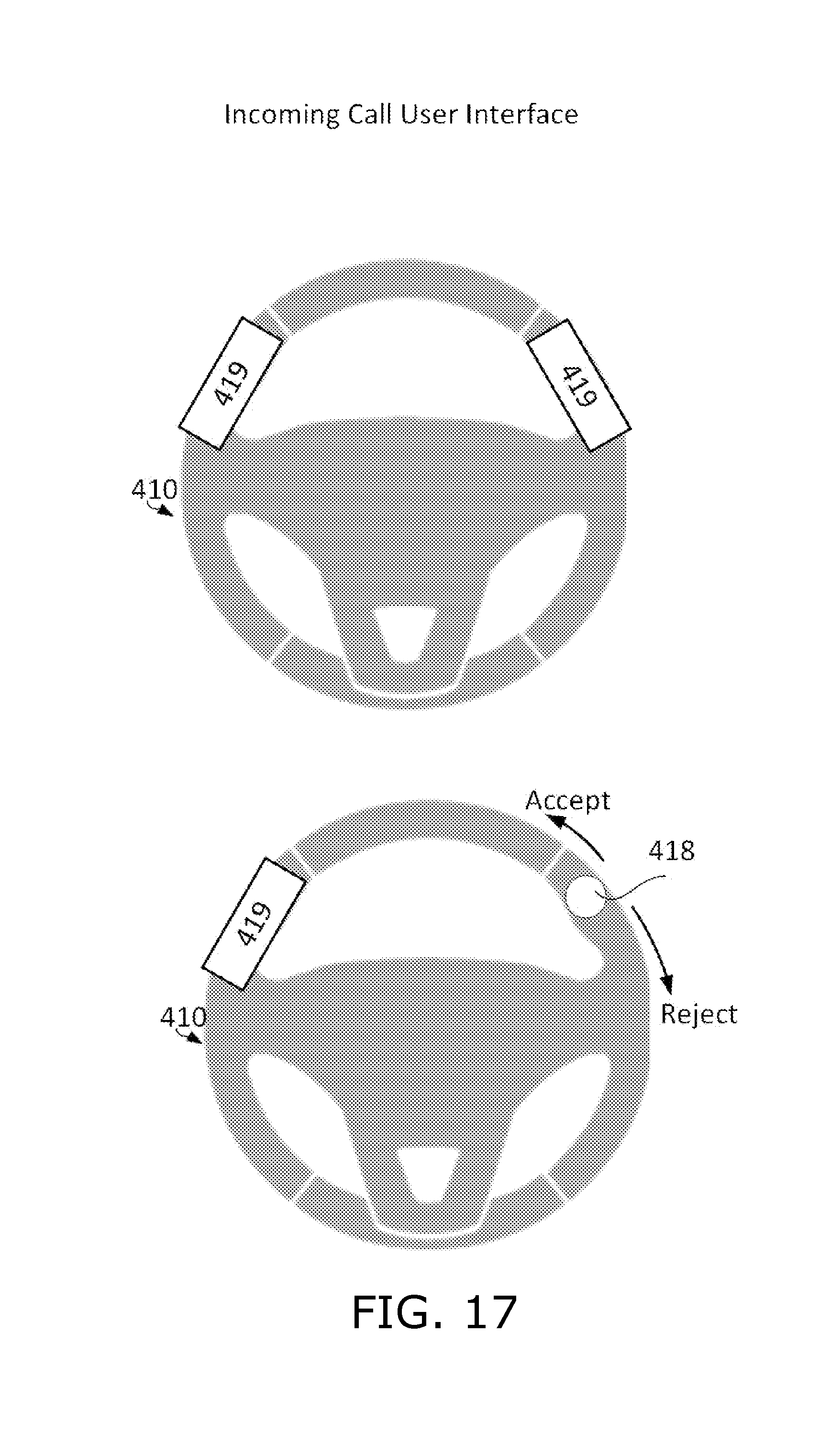
FIG. 17 is a simplified illustration showing how an incoming call is received, in accordance with an embodiment of the present invention;
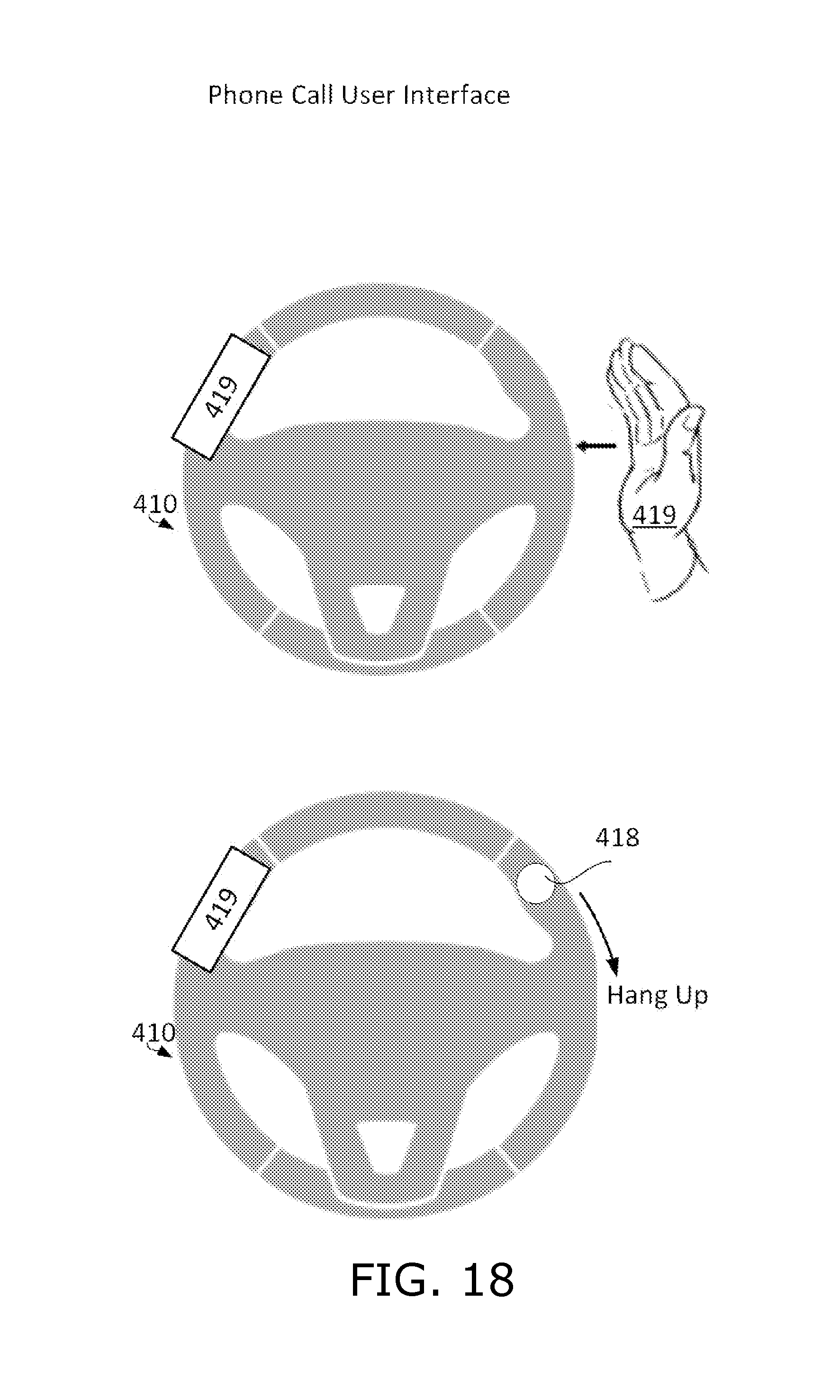
FIG. 18 is a simplified illustration showing how to hang up a call, in accordance with an embodiment of the present invention; and
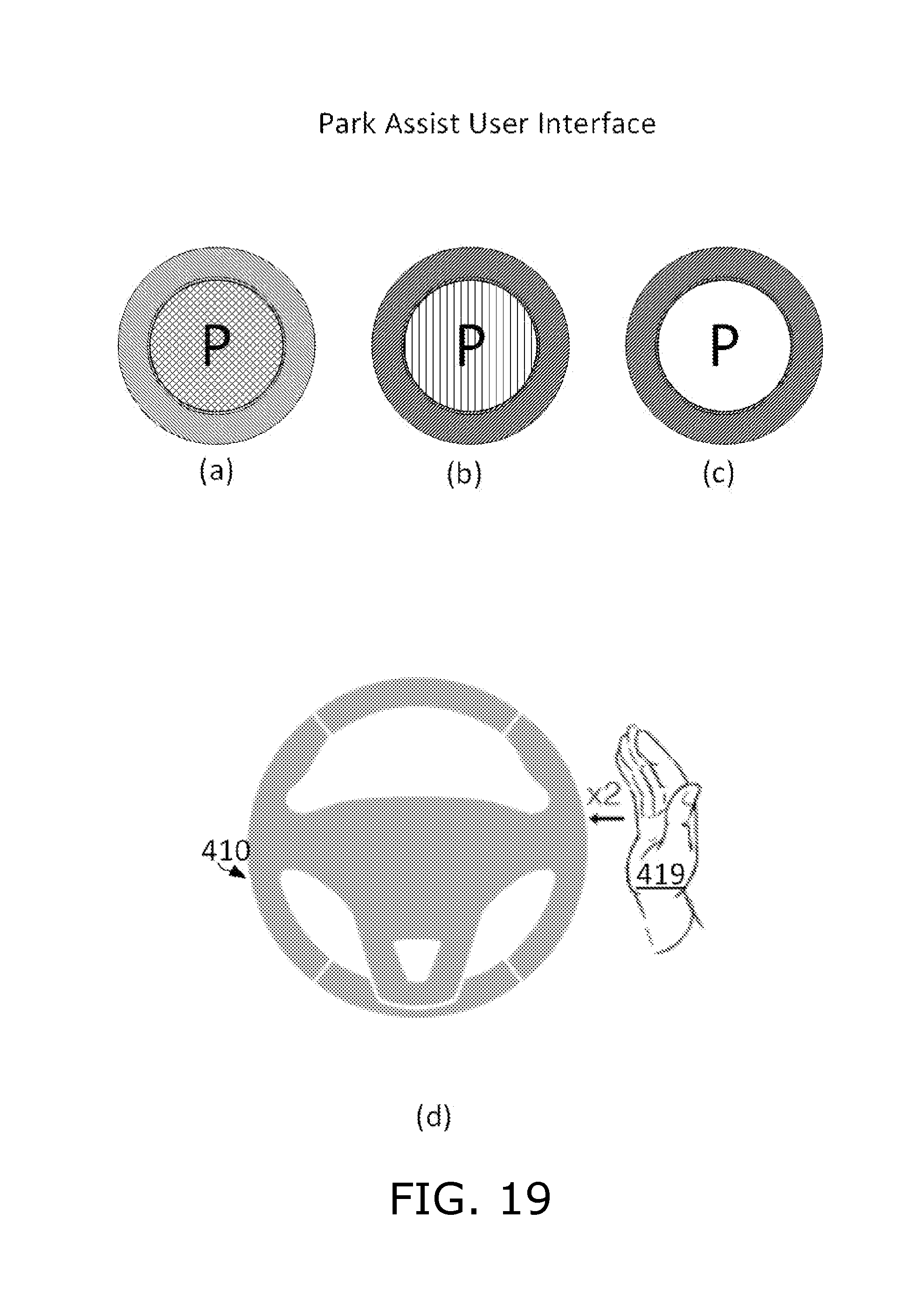
FIG. 19 is a simplified illustration of a user interface for a park assist function, in accordance with an embodiment of the present invention.
In the disclosure and figures, the following numbering scheme is used. Light transmitters are numbered in the 100's, light detectors are numbered in the 200's, light guides and lenses are numbered in the 300's, miscellaneous items are numbered in the 400's, light beams are numbered in the 600's, and flow chart elements are numbered 1000-1100. Like numbered elements are similar but not necessarily identical.
The following tables catalog the numbered elements and list the figures in which each numbered element appears.
TABLE-US-00001 Light Transmitters Element FIGS. 100 4, 5 101 6 102 6 105 8-10 106 6, 7 107 6, 7 108 6, 7 109 6, 7
TABLE-US-00002 Light Detectors Element FIGS. 200 4 201 6, 8, 9 202 6, 8, 9 203 8, 9 205 8, 9 206 8
TABLE-US-00003 Light Guides and Lenses Element FIGS. 300 2-7 301 8, 9 302 8, 9 303 8, 9 304 8, 9 305 8-10
TABLE-US-00004 Miscellaneous Items Element FIGS. Description 400 1 steering wheel 401 1 grip 402 1 right spoke 403 1 left spoke 404 1 bottom spoke 405 1 answer button 406 1 reject button 410 12, 14-19 steering wheel 411 2-5 steering wheel frame 412 2-5 top cover 413 2-5 thumb notch 414 2-7 PCB 415 2-5, 7 light baffle 416 3, 5 transparent cover section 417 3, 5 transparent cover section 418 12, 14, 15, 17, 18 finger 419 12, 14, 16-19 hand 420 12, 15 steering wheel surface 421-424, 428, 12, 15 hand/finger movement directions 431-434 425 12 clock icon 426 12 finger 430 14 double-tap gesture 436 14-16 Illumination 437 14 movement of illumination 438 14, 17 tap gesture 440 6, 11 Processor 441-443 11 network client 444 11 message bus
TABLE-US-00005 Light Beams Element FIGS. Description 601 10 light beam 602 3, 8-10 light beam 603 8, 9 light beam 604 8, 9 light beam
TABLE-US-00006 Flow Chart Stages Element FIGS. Description 1001-1005 13 vehicle application state 1010-1019 13 vehicle application action
DETAILED DESCRIPTION
Aspects of the present disclosure relate to light-based touch controls that allow a driver to keep his hands on a steering element while operating peripheral electronic devices and automated features in a vehicle.
According to a first embodiment of the invention, a steering wheel is provided with a touch sensitive strip disposed along the entire circumference of the steering wheel. In order to facilitate locating the strip, it is disposed in a thumb receiving notch or groove that is etched or otherwise formed along the circumference of the steering wheel. In addition to a touch sensor, there is also a visible-light illuminator behind or around the touch sensitive strip that is used to indicate the state of the user interface to the user, and also indicate where certain tap gestures should be performed.
A user interface for this steering wheel is designed to be independent of the rotation of the steering wheel. Sweep gestures are clockwise and counter-clockwise so that they are independent of rotation of the wheel. A function is activated in response to a gesture, such as a double-tap, performed anywhere along the circumference of the wheel. The activation of some functions places the user interface into a state in which one or more additional functions can be selectively activated. In order to activate these additional functions, the touch location at which the initial gesture was performed is illuminated and subsequent gestures are performed in relation to the illuminated portion of the wheel. When a portion of the wheel is thus illuminated, and the driver slides his hand along the steering wheel grip, the illuminated portion of the steering wheel follows the hand so that the hand is always next to the location for performing subsequent gestures. Similarly, when the user switches hands gripping the steering wheel, the illumination jumps to the newly gripped part of the wheel.
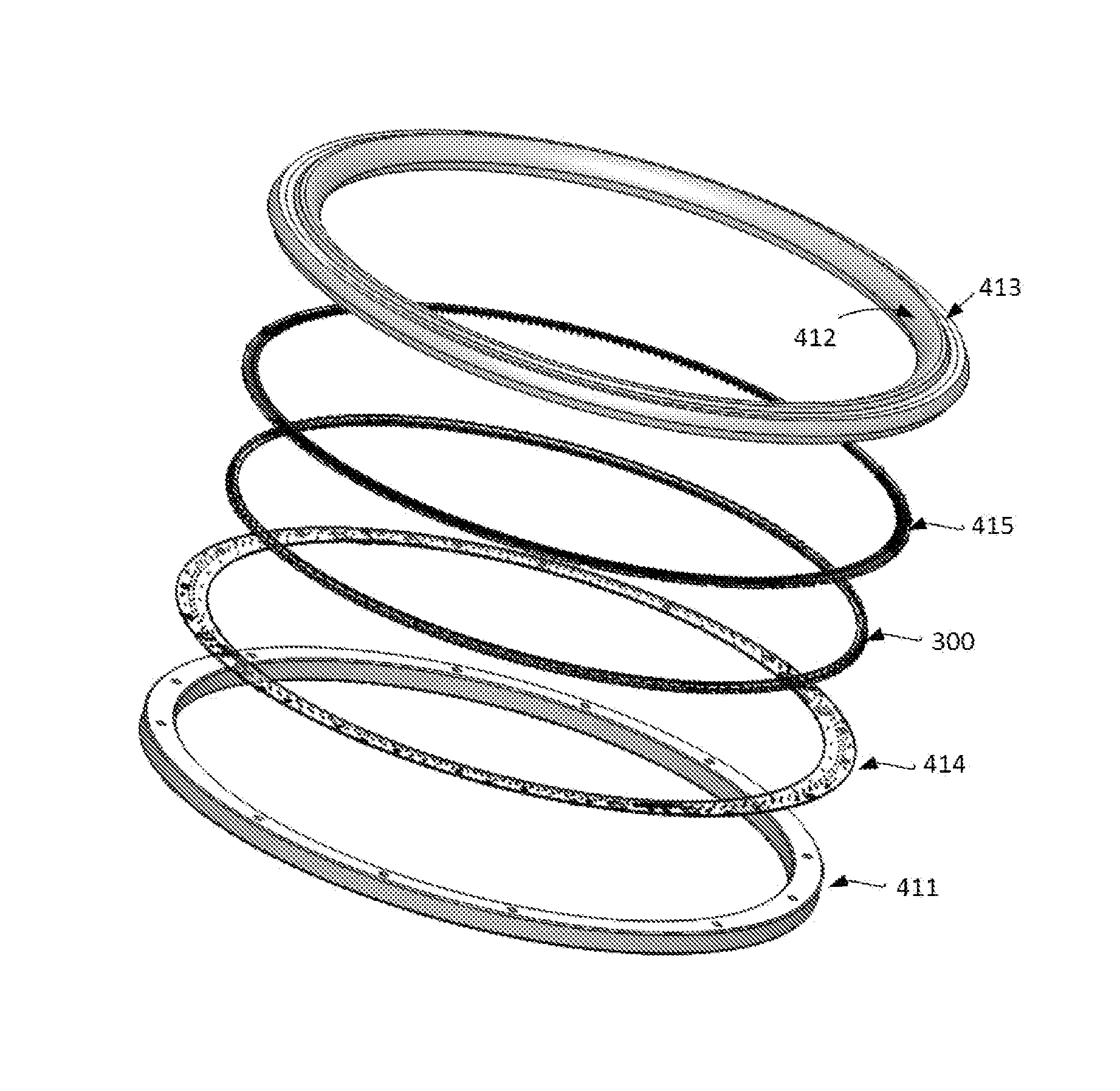
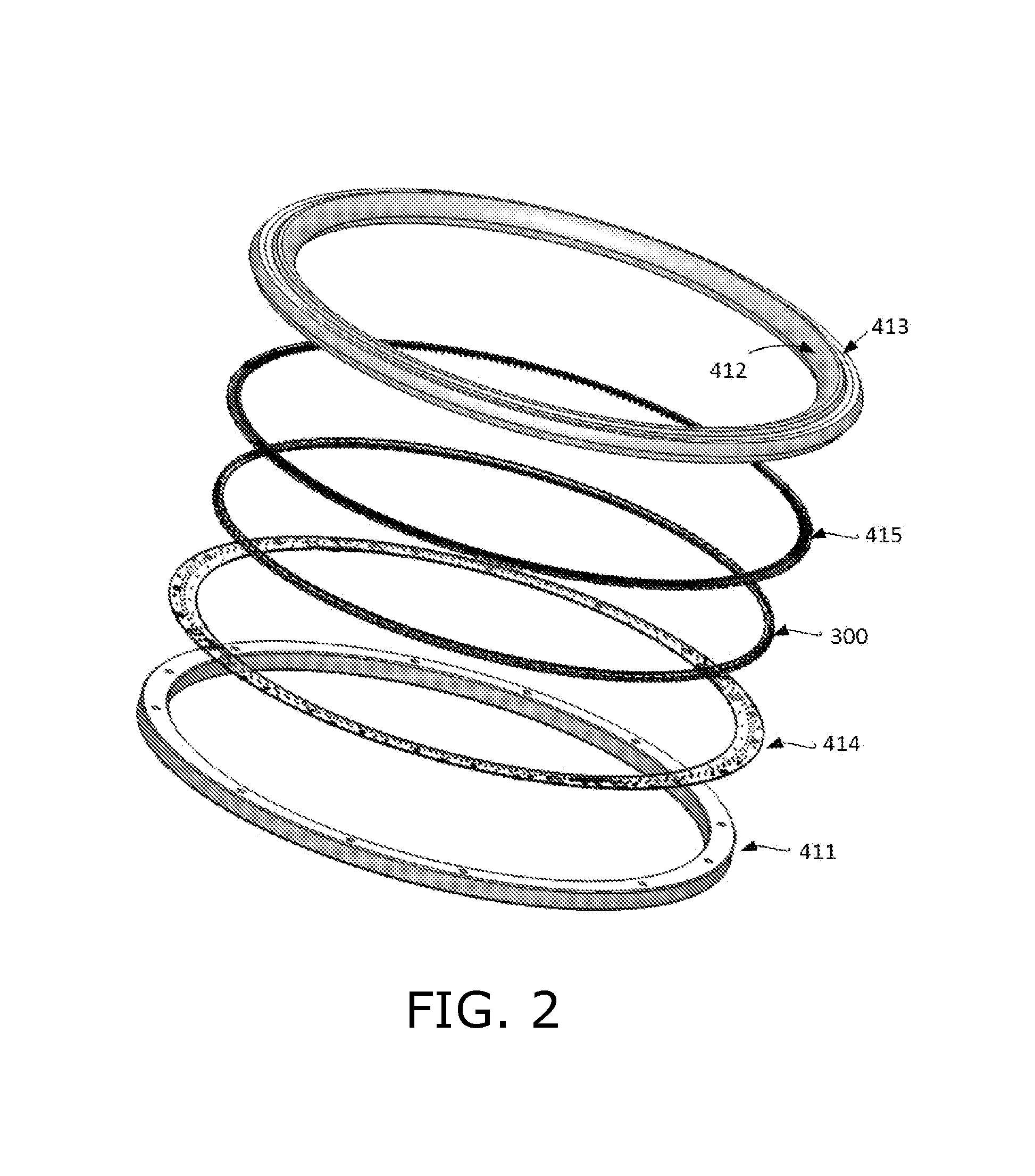
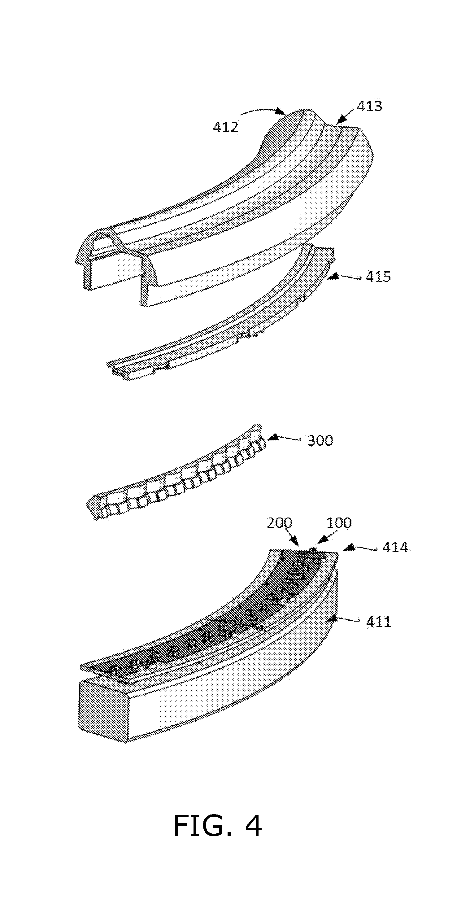
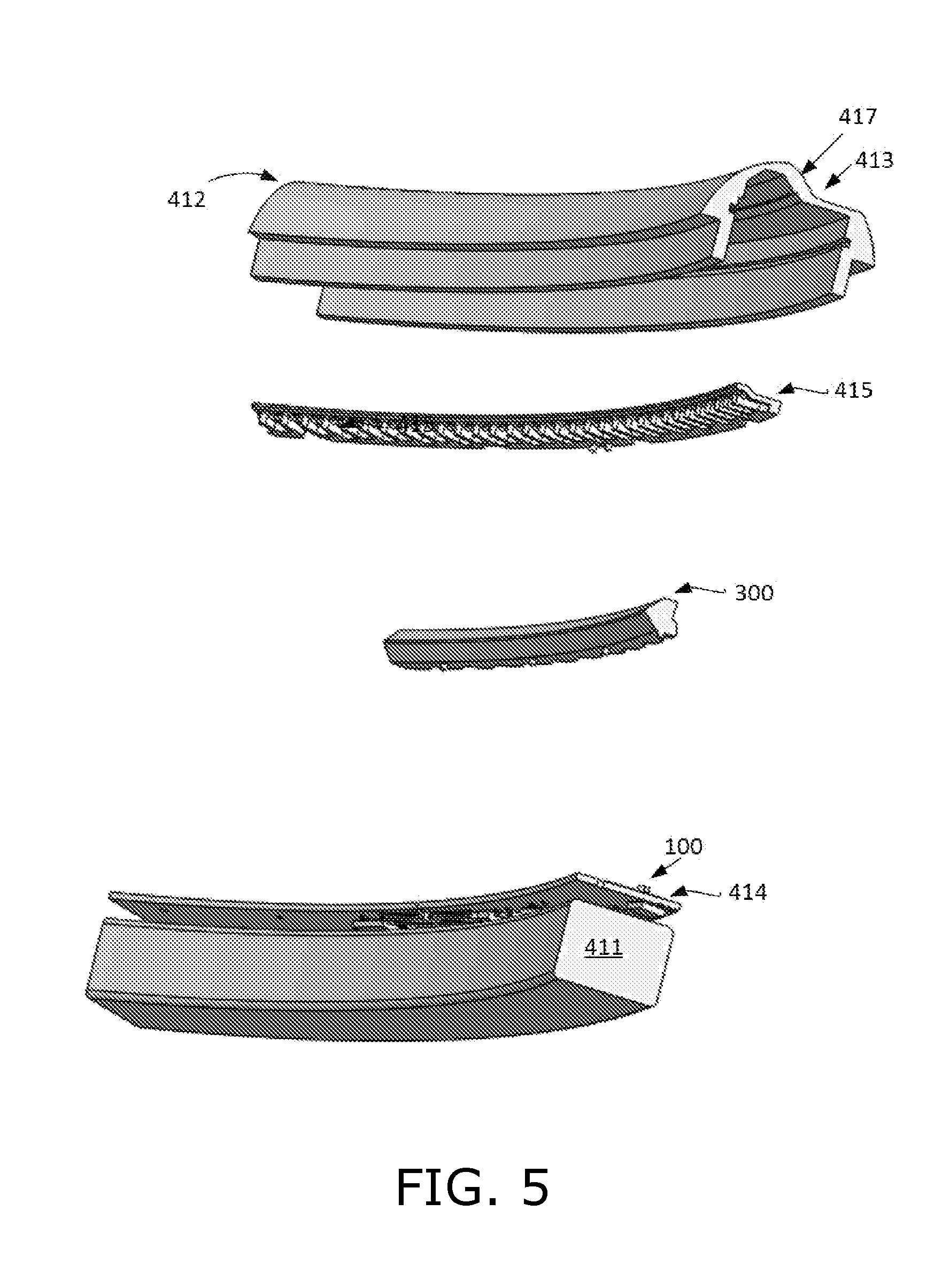
Reference is made to FIG. 2, which is an exploded view of a steering wheel, in accordance with a first embodiment of the present invention. Elements of this steering wheel include steering wheel frame 411, PCB 414, an array of lenses 300, a light baffle structure 415, and a steering wheel top cover 412. A thumb-receiving notch 413 is disposed within steering wheel cover 412.
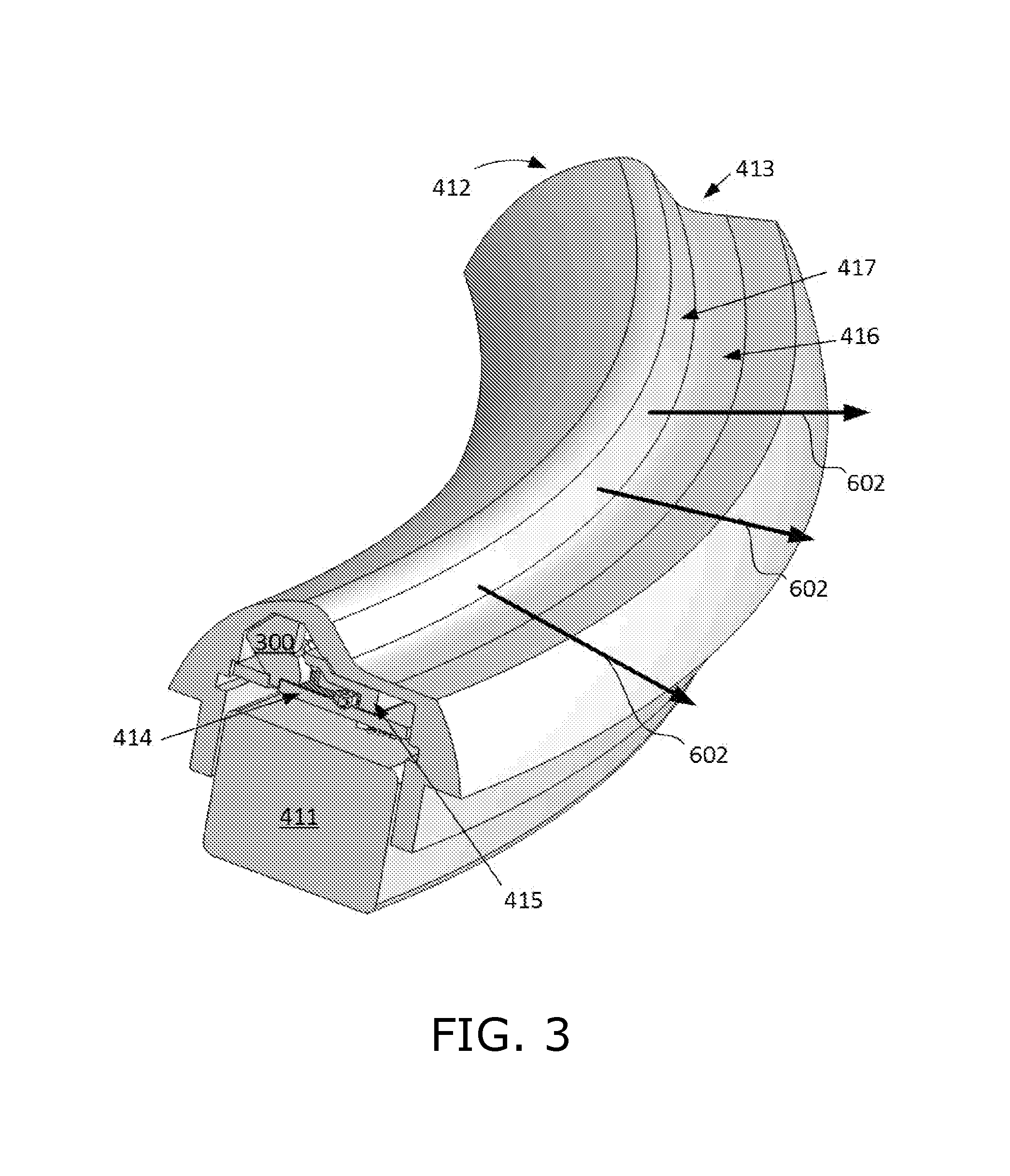
Reference is made to FIG. 3, which is a cutaway view of a segment of the steering wheel of FIG. 2, in accordance with an embodiment of the present invention. Thumb-receiving notch 413 is illustrated in FIG. 3. Two light transmissive portions of cover 412 are also shown in FIG. 3. A first light transmissive portion 417 forms the side wall of thumb-receiving notch 413. Light beams traveling into and out of this portion provide touch detection and proximity detection, as explained below. Three touch detection light beams 602 are shown directed radially outward from the steering wheel gripping element. The second light transmissive portion 416 forms a floor of thumb-receiving notch 413, and is used for visible illumination indicating a state of the user interface to the driver, and at which location the driver should perform additional user interface gestures.
Reference is made to FIGS. 4 and 5, which are exploded views of the steering wheel segment illustrated in FIG. 3, in accordance with an embodiment of the present invention. As shown in FIG. 4, two concentric rows of elements are mounted on PCB 414. Namely, an inner row of light detectors 200 and an outer row of light emitters 100. Light from the emitters enters lenses 300 through which it is re-directed out of the steering wheel through light transmissive portion 417 as light beams 602, illustrated in FIGS. 3 and 8-10. An object such as a thumb placed in notch 413 reflects the light back through portion 417 and lenses 300 onto one or more of the light detectors 200, thereby providing touch detection, as illustrated in FIGS. 8 and 9. Similarly, an object such as a user's hand placed along the outer rim of the steering wheel outside notch 413 and opposite light transmissive portion 417 also reflects the light back through portion 417 and lenses 300 onto one or more of the light detectors 200, thereby providing proximity detection.
FIG. 5 shows an exploded view from below of the steering wheel segment illustrated in FIG. 3, in accordance with an embodiment of the present invention.
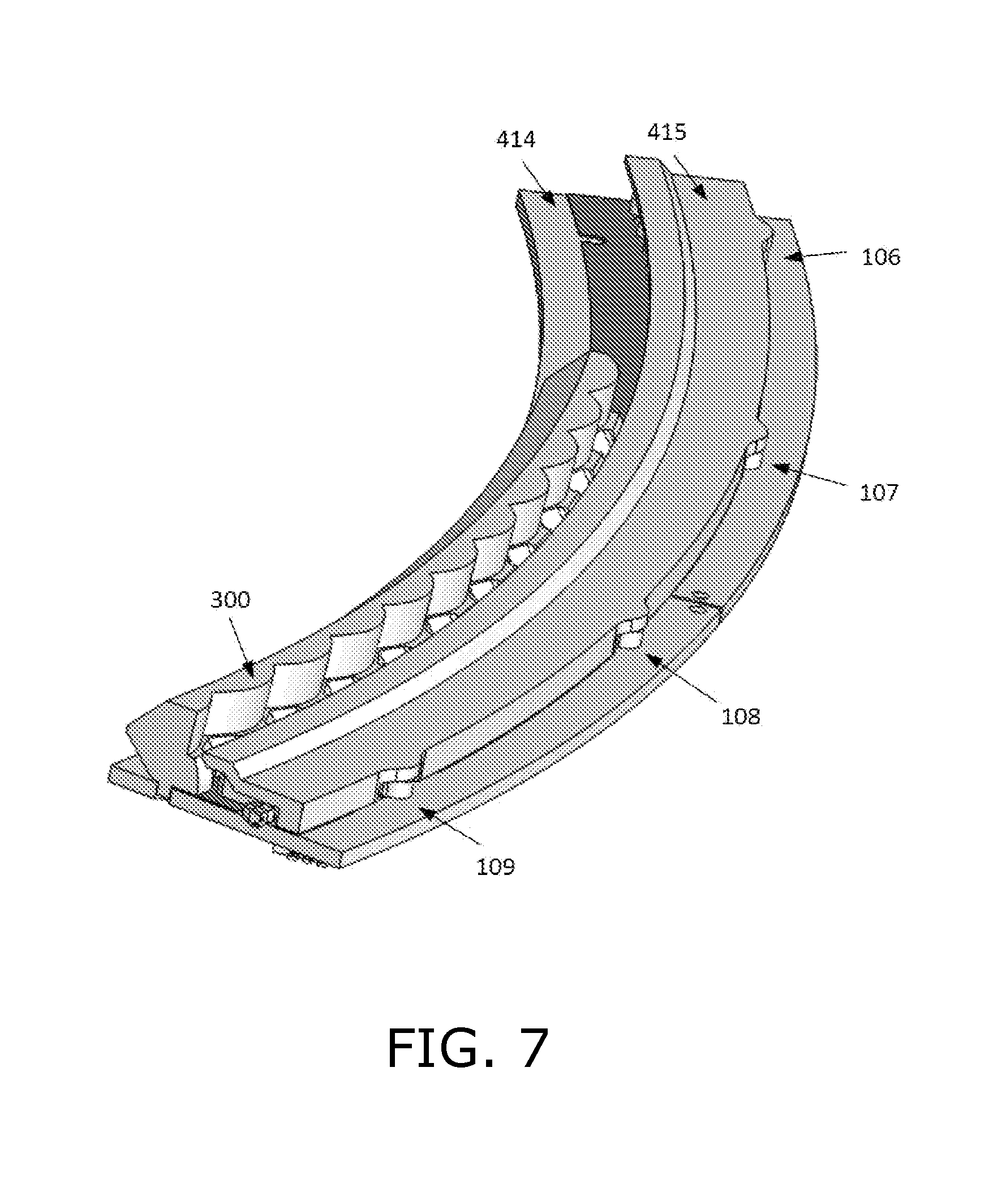
Reference is made to FIG. 6, which is a simplified illustration of electronic components in the steering wheel segment of FIG. 2 connected to a processor, in accordance with an embodiment of the present invention. FIG. 6 shows processor 440 connected to PCB 414 on which three concentric arrangements of light elements are mounted, namely, an inner circular arrangement of inward facing light detectors, including detectors 201 and 202; a middle circular arrangement of inward facing light emitters, including emitters 101 and 102; and an outer circular arrangement of outward facing light emitters 105-108. The inward facing light emitters are used for touch and proximity detection and typically emit light in the near infrared range. Processor 440 controls activation of the emitters and detectors, and detects gestures performed on the steering wheel based on these activations and based on the outputs of the detectors.
The outward facing light emitters are used to provide visual indications to the user by illuminating light transmissive portion 416 of the steering wheel cover, and emit light in the visible range. Lenses 300 are described in assignee's U.S. application Ser. No. 14/555,731, entitled DOOR HANDLE WITH OPTICAL PROXIMITY SENSORS, the contents of which are incorporated herein in their entirety by reference.
Reference is made to FIG. 7, which is a simplified illustration of a structure of light baffles placed upon the electronic components in FIG. 6, in accordance with an embodiment of the present invention. FIG. 7 shows PCB 414 and lenses 300 of FIG. 6, but with baffle structure 415 placed above the mounted light elements.
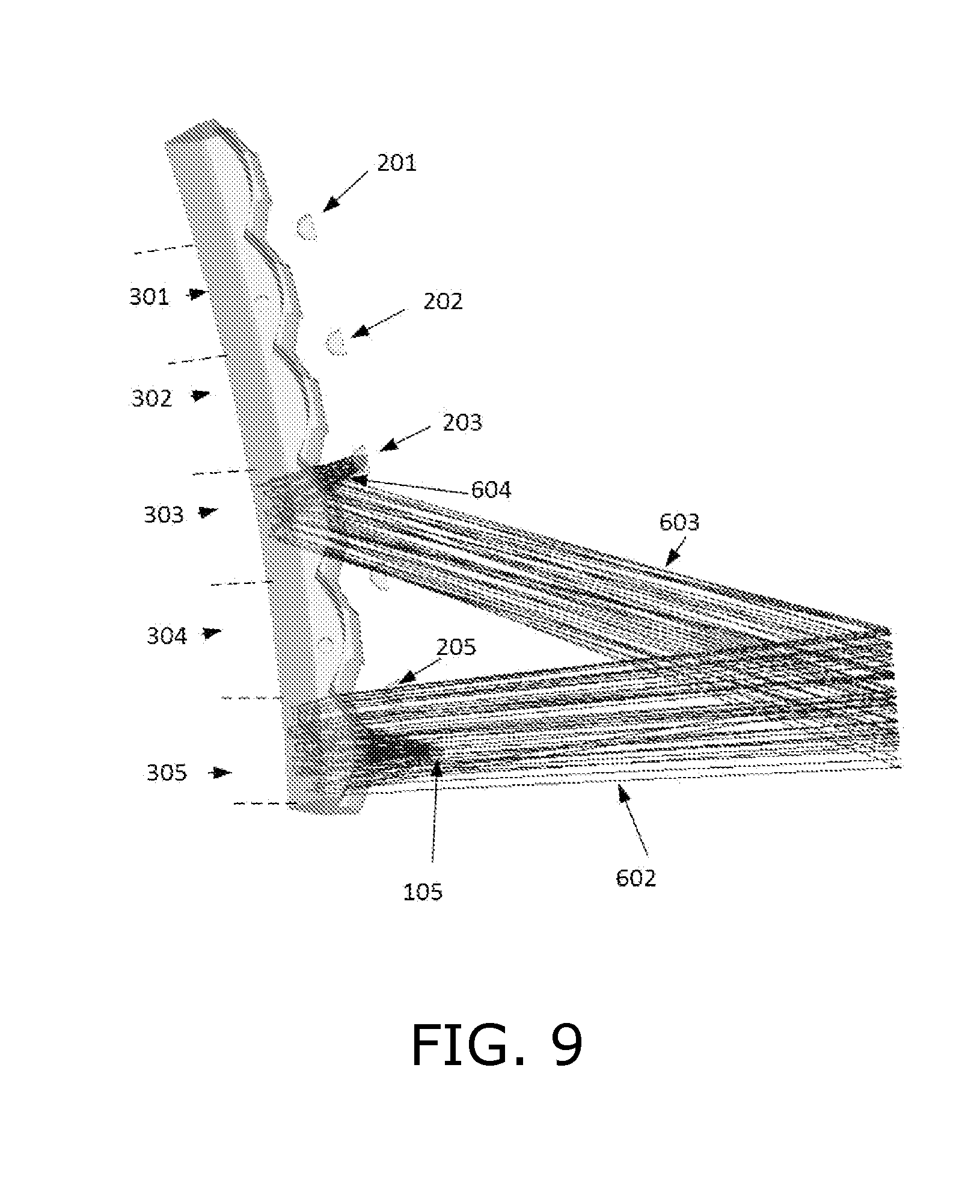
Reference is made to FIGS. 8 and 9, which are simplified illustrations of light beams detecting an object, in accordance with an embodiment of the present invention. FIGS. 8 and 9 show a light path used to detect an object. Shown in FIGS. 8 and 9 are individual lens structures 301-305. Each lens structure serves a respective opposite emitter and two detectors, one to the left of the emitter and one to the right of the emitter. Thus, for example, lens structure 305 serves emitter 105 and detectors 205 and 206. In addition each detector is served by two lens structures; e.g., detector 205 receives reflected light from lens structures 304 and 305. In the example shown in FIGS. 8 and 9, light from emitter 105 is reflected by an object (not shown) into lens structure 303 and onto detector 203. Three segments of the detected light are indicated in FIGS. 8 and 9; namely, light beam 602 projected outward from lens structure 305 and radially outward of the steering wheel, light beam 603 reflected by the object into lens structure 303, and light beam 604 directed by lens structure 303 onto detector 203.
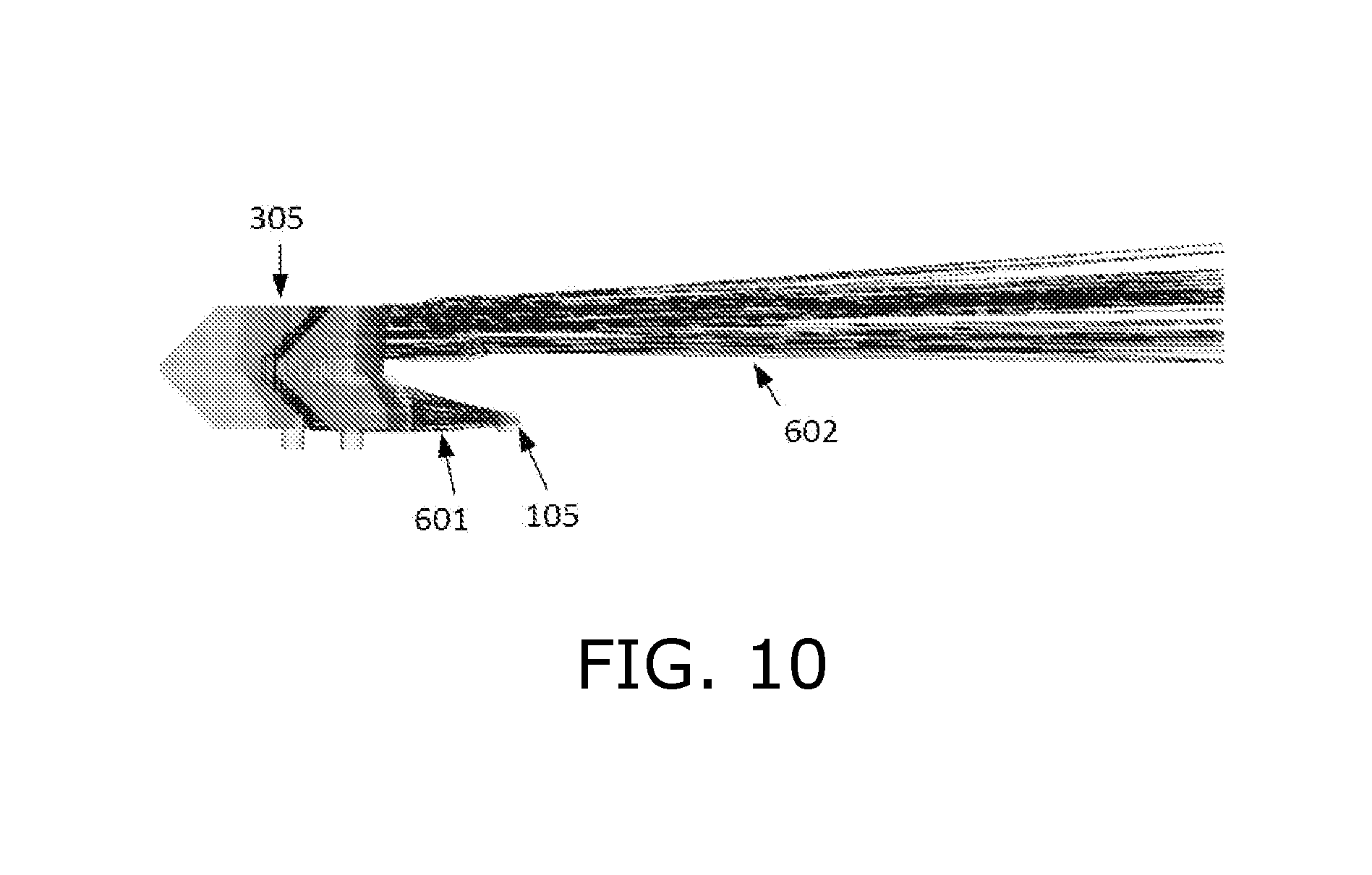
Reference is made to FIG. 10, which is a simplified side view illustration of light beams projected radially outward from a steering wheel, in accordance with an embodiment of the present invention. FIG. 10 shows a cutaway side view of the light path illustrated in FIGS. 8 and 9. FIG. 10 shows light beam 601 from emitter 105 entering lens structure 305, where it is redirected outward as light beam 602.
Methods for determining two-dimensional coordinates of an object detected by the disclosed proximity sensor array are described in assignee's U.S. application Ser. No. 14/312,787, entitled OPTICAL PROXIMITY SENSORS, and U.S. application Ser. No. 14/555,731, entitled DOOR HANDLE WITH OPTICAL PROXIMITY SENSORS, both incorporated herein in their entireties by reference. Because the present application is for a steering wheel and the proximity sensor array is arranged along an arc-shaped grip of the steering wheel, the determined coordinates are polar coordinates, including a polar angle and a radial coordinate. The polar angle corresponds to a coordinate along the proximity sensor array, which in U.S. application Ser. Nos. 14/312,787 and 14/555,731 is described as an x-axis coordinate. The radial coordinate corresponds to a distance from the proximity sensor array, which in U.S. application Ser. Nos. 14/312,787 and 14/555,731 is described as a y-axis coordinate.
Discussion now turns to the firmware and software used to detect and interpret user gestures. There are five basic gesture components that are detected by the hardware and low level drivers: (i) Thumb-Tap, (ii) Thumb-Glide, (iii) Thumb-Long-Press, (iv) Grab and (v) Rim-Tap. These components are emitted on the network as they are detected, and are used by higher level software to assemble more complex gestures such as double-taps. Application software interprets these gestures as input commands. In some embodiments of the invention multiple client applications are connected via a network to the detector firmware. The firmware sends information for each detected gesture component over the network, and a client application translates that information into commands and/or constructs compound gestures from multiple gesture components.
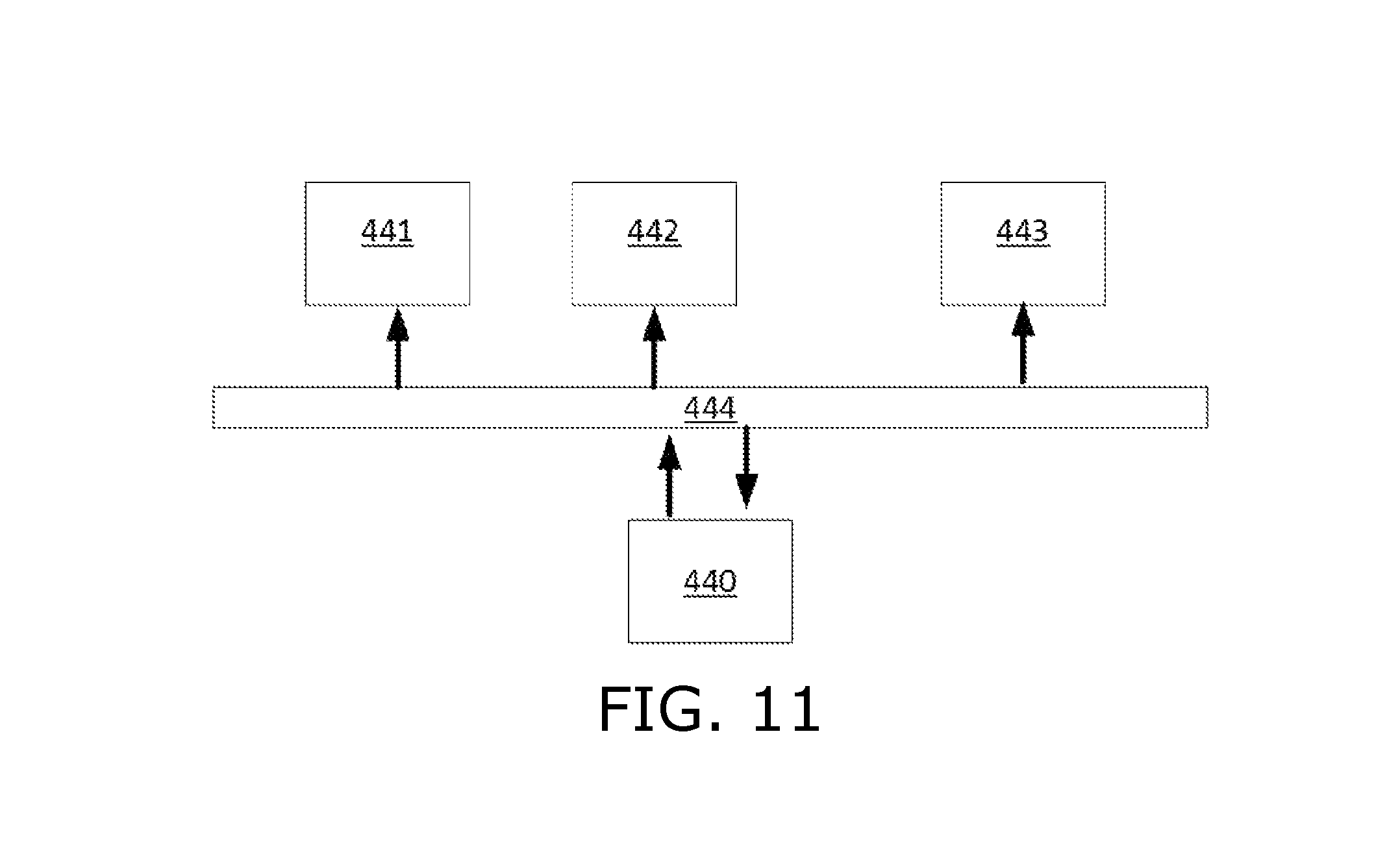
Reference is made to FIG. 11, which is a simplified illustration of communication between touch detection firmware and multiple clients over a network, in accordance with an embodiment of the present invention. FIG. 11 shows an exemplary network architecture in which processor 440 sends detected gesture components over message bus 444, e.g., using the Message Queue Telemetry Transport (MQTT) messaging protocol on top of the TCP/IP protocol, to connected clients 441-443.
The five basic gesture components are categorized according to whether they are performed by a large object (hand) or small object (thumb), and whether the nature of the gesture component is discrete or continuous, as presented in the table below.
TABLE-US-00007 Component Description Object Type Thumb-Tap Tap thumb on steering Small Discrete wheel rim Thumb-Glide Glide thumb along Small Continuous steering wheel rim Thumb-Long- Hold thumb on steering Small Continuous Press wheel rim Grab Grab hold of steering Large Continuous wheel rim Rim-Tap Tap hand on steering Large Discrete wheel rim
These gesture components are alternatively referred to as follows.
TABLE-US-00008 Component Alternative Name Thumb-Tap small-object tap Thumb-Glide small-object glide Thumb-Long-Press small-object touch-and-hold Grab large-object grab Rim-Tap large-object tap
The parameters are the same for all gesture components; namely, time stamp, start angle (min_angle), end angle (max_angle), center angle (angle) and state.
The angle parameters refer to a polar angle along the steering wheel at which the object is detected. Because of the object's size, there is a first polar angle at which the object begins (start angle) and a last polar angle at which the object ends (end angle). The midpoint between the start and end angles (center angle) is used as the object's polar angle. The start and end angles are useful for determining the size of a detected object.
The state parameter takes on three values: RECOGNIZED, UPDATED and ENDED. The ENDED state is applied to all discrete gesture components, and also when a continuous gesture component ends. The RECOGNIZED and UPDATED states are only applied to continuous gesture components. The RECOGNIZED state is applied when a continuous gesture component is first detected. The UPDATED state is applied during the course of a continuous gesture component.
The discrete gesture components, Thumb-Tap and Rim-Tap, are emitted to the clients after they happen, and then only one message is sent for the gesture component. They are only sent with the state ENDED.
The continuous gesture components, Thumb-Glide, Thumb-Long-Press and Grab, are emitted to the clients intermittently from the instant that they are recognized until they end when the hand or finger leaves the rim. When they are first recognized, they are sent to the network with the state RECOGNIZED. With a configurable interval, the gesture component is reported to the network with new parameters and the state UPDATED. When the gesture component ends, the gesture component is sent with the state ENDED.
Reference is made to FIG. 12, which is a simplified illustration of five basic gesture components used in a steering wheel user interface, in accordance with an embodiment of the present invention. FIG. 12 shows the five gesture components performed by thumb 418 and hand 419 on steering wheel 410. Some gesture components are illustrated both from above and from the side. When illustrated from the side, thumb 418 is shown interacting with steering wheel surface 420.
A Thumb-Tap gesture component is generated when a small object touches the rim (or gets very close) and then is lifted from the rim within a short period. This period is configurable, but typically it is 100-200 ms. FIG. 12 shows the Thumb-Tap gesture component from above and from the side, and illustrates the movement of thumb 418 by arrows 421.
A Rim-Tap gesture component is the same as a Thumb-Tap, but for a large object such as a hand. FIG. 12 shows the Rim-Tap gesture component from the side and illustrates the movement of hand 419 by arrows 424.
A Thumb-Glide gesture component is generated when a small object touches the rim and moves at least a certain threshold distance along the rim. That distance is configurable. When it continues to move, UPDATE messages are sent when the object has moved a certain distance, also configurable. FIG. 12 shows the Thumb-Glide gesture component from above and from the side, and illustrates the movement of thumb 418 by arrows 422 and 423.
A Grab gesture component is the same as a Thumb-Glide gesture component, but for a large object touching the rim, and with the difference that the Grab gesture component does not have to move to be reported on the network. When the hand has been on the rim for a certain time threshold, the Grab gesture component is recognized and messages are intermittently sent to the network. FIG. 12 shows the Grab gesture component from above by showing hand 419 gripping steering wheel 410.
A Thumb-Long-Press gesture component is generated when a small object is present, and not moving, on the rim. When the small object has been present for a certain time, messages are sent intermittently to the network about the gesture component. If the object starts moving, the Thumb-Long-Press gesture component is ended and a Thumb-Glide gesture component is started instead. FIG. 12 shows the Thumb-Long-Press gesture component from above and from the side. Clock icon 425 indicates the time threshold required to distinguish this gesture component from a Thumb-Tap.
As mentioned above, gesture components are combined into compound user interface gestures. In some cases, environment conditions at the gesture location are combined with the gesture component to define a gesture. For example, a Thumb-Tap gesture performed at one end of an illuminated portion of the rim is translated into a first command, and a Thumb-Tap gesture performed at the other end of the illuminated portion of the rim is translated into a second command. The following table lists the different gestures and compound gestures in the steering wheel user interface, the gesture components that make up each gesture, additional gesture parameters, and example context and commands for each gesture.
TABLE-US-00009 Gesture Additional Example Example Gesture Components Parameters Context Command Tap inside Thumb-Tap Thumb-tap Cruise Increase or notch performed at top or control is decrease cruise bottom of illuminated active control speed in portion of illuminated 5 mph segment of steering increments wheel Tap on Rim-Tap During Reactivate phone steering phone call interaction, e.g., wheel outer when phone call rim is active for set period of time. Enables hanging up the phone call with a clockwise swipe gesture Single Two Thumb- Thumb-taps have Vehicle is in Activate cruise object Taps different time stamps, motion control and double-tap similar center illuminate inside notch angles location of double-tap Single Two Rim-Taps Side of steering Car is not Activate Park object wheel rim (left or moving, and Assist to park on double-tap right) at which Park Assist left or right side on steering double-tap is icon is of car, based on wheel outer performed displayed on tapped side of rim HUD rim Multi-touch Two Thumb- Thumb-taps have Autonomous Activate double-tap Taps similar time stamps, drive is not autonomous inside notch different center active drive angles Extended Thumb-Long- Thumb-long-press Cruise Increase or touch inside Press performed at top or control is decrease cruise notch bottom of illuminated active control speed in portion of illuminated 1 mph segment of steering increments wheel Grab Grab Autonomous Deactivate drive is autonomous active drive, and enter cruise control mode Swipe Thumb-Glide clockwise/counter- Cruise Increase or clockwise control is decrease distance active from forward car in cruise control mode Radial swipe Thumb-Glide Thumb-glide data Cruise Open cruise structures have control is control menu on similar center angles active HUD and different radial coordinates Slide Grab Grab data structures Portion of Move illumination have different time steering to new hand stamps and different wheel is location (follow center angles selectively slide movement) illuminated Switch Grab Grab data structures Portion of Move illumination hands have different time steering to new hand stamps and different wheel is location (jump to center angles selectively other side of illuminated wheel)
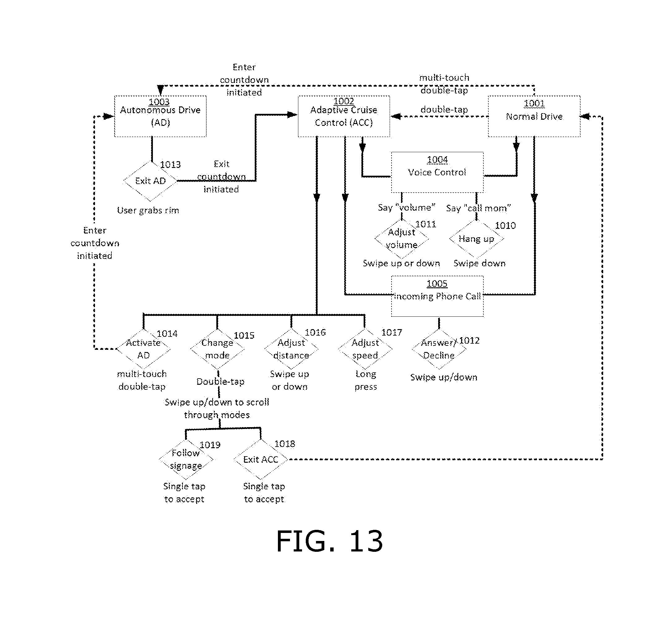
Reference is made to FIG. 13, which is a flowchart of an exemplary vehicle user interface, in accordance with an embodiment of the present invention. The flowchart illustrates the different application states, different commands within each state, and the gestures used to issue those commands. The details of the gestures are illustrated in FIGS. 14-19. In some embodiments a heads-up display (HUD) is provided.
The flowchart of FIG. 13 illustrates a highway scenario that includes three driving modes: Normal Drive 1001, Adaptive Cruise Control 1002 and Autonomous Drive 1003. In Normal Drive mode, the driver steers the vehicle and controls its speed. In Adaptive Cruise Control mode the driver steers the vehicle but the vehicle's speed, its distance from the next vehicle on the road, and other parameters are controlled by the vehicle. In Autonomous Drive mode the vehicle is driven and steered automatically without driver input.
The user enters Adaptive Cruise Control mode from Normal Drive mode by performing a double-tap gesture. The user enters Autonomous Drive mode from Normal Drive mode and from Adaptive Cruise Control mode by performing a multi-touch double-tap gesture. These gestures are described below. In order to alert the driver that Autonomous Drive mode will begin shortly, the steering wheel is illuminated with an illumination pattern that indicates a countdown until Autonomous Drive is activated.
The user exits Adaptive Cruise Control mode by performing a double-tap gesture that opens a menu on the HUD for changing the mode 1015 of cruise control. The user performs clockwise or counter-clockwise swipe gestures to scroll through the different modes on the HUD, and performs a single-tap gesture to select the displayed mode. One of the modes is Exit ACC 1018, and selecting this mode exits Adaptive Cruise Control. Another mode configures the cruise control application to follow the road signage 1019.
The user exits Autonomous Drive mode 1013 by grabbing the rim of the steering wheel. In order to alert the driver that Autonomous Drive mode is about to exit, the steering wheel is illuminated with an illumination pattern that indicates a countdown until Autonomous Drive is deactivated. Upon exiting Autonomous Drive mode, the vehicle enters Adaptive Cruise Control mode.
In Adaptive Cruise Control mode 1002 the user adjusts a distance 1016 between the vehicle and the vehicle directly in front of it, by performing a clockwise or counter-clockwise swipe gesture. The user adjusts the speed of the vehicle by performing either a tap gesture or an extended touch gesture. When the vehicle enters Adaptive Cruise Control mode 1002 a segment of the steering wheel is illuminated. A tap gesture or extended touch gesture at one end of the illuminated segment increases the vehicle speed, and a tap gesture or extended touch gesture at the other end of the illuminated segment decreases the vehicle speed.
A voice control state 1004 can be entered from Normal Drive mode and Adaptive Cruise Control mode. In this state, the user can initiate a phone call by saying "call" and the name of a contact from his phone's contact list. Once the call has been connected, the user can hang up 1010 by performing a clockwise swipe gesture. The user can also adjust the volume 1011 by saying the word "volume" and then performing a counter-clockwise swipe gesture to raise the volume, or a clockwise swipe gesture to lower the volume.
When an incoming phone call 1005 is received, the user can answer the call 1012 by performing a counter-clockwise swipe gesture, or decline the call 1012 by performing a clockwise swipe gesture.
Reference is made to FIG. 14, which is a simplified illustration of user interface gestures performed on a steering wheel for an exemplary adaptive cruise control function, in accordance with an embodiment of the present invention. In order to enter Adaptive Cruise Control mode from Normal Drive mode the user performs a single object double-tap gesture. Namely, the user taps twice with his thumb on the thumb notch in the steering wheel. This gesture is illustrated in drawing (a) in FIG. 14, showing steering wheel 410, hand 419 gripping steering wheel 410, and double-tap gesture 430. The present invention enables the user to perform the double-tap gesture 430 at any location along the perimeter of steering wheel 410.
When Adaptive Cruise Control is active the user has four options; namely, adjust cruise control speed, adjust the distance between the vehicle and the vehicle ahead, open an adaptive cruise control menu, and activate Autonomous Drive mode. As mentioned above Adaptive Cruise Control is activated when the user taps twice with his thumb in the steering wheel thumb notch. The location of these taps is subsequently illuminated to indicate to the user where to perform future gestures. This is illustrated in drawing (b) in FIG. 14, showing illuminated segment 436 of the steering wheel 410 at the location at which double-tap 430 was performed. Thus, to increase the cruise control speed the user performs a gesture, e.g. a single-tap, above the illuminated portion. This is illustrated in drawing (d) in FIG. 14 showing tap gesture 438 at the counter-clockwise edge of illuminated portion 436. The "+" indicates that this gesture increases the speed of the vehicle. Drawing (e) in FIG. 14 shows gesture 438 performed at the clockwise end of illuminated portion 436, and the "-" indicates that the gesture decreases the speed of the vehicle.
If the user slides his hand 419 along steering wheel 410, the illuminated portion 436 moves with the hand so that the user's thumb is always next to the illuminated portion of the steering wheel. This is illustrated in drawing (c) in FIG. 14, in which hand 419 gripping steering wheel 410 slides clockwise as indicated by arrow 428, and illuminated portion 436 also slides in the same direction as indicated by arrow 437.
In some embodiments the cruise control speed is also adjusted in response to extended touch gestures above and below the illuminated portion of the steering wheel. For example, the speed is adjusted by 5 km/h in response to a tap gesture, and is adjusted by 1 km/h in response to an extended touch gesture.
In order to increase or decrease the distance between the vehicle and the vehicle in front of it on the road, the user performs clockwise and counter-clockwise swipe gestures. These are illustrated in drawings (f) and (g) in FIG. 14. Drawing (f) illustrates a counter-clockwise gesture 431 to increase the distance between vehicles, and drawing (g) illustrates a clockwise gesture 432 to decrease the distance between vehicles.
In order to change the mode of Adaptive Cruise Control the user performs a radial swipe gesture with his thumb across the width of the steering wheel thumb notch. This is illustrated in drawings (h) and (i) in FIG. 14. Drawing (h) illustrates swipe gesture 433 that moves outward across the width of illuminated portion 436. Drawing (i) illustrates swipe gesture 434 that moves inward across the width of illuminated portion 436. Either gesture causes the HUD to present a mode option for selection. The user performs a single-tap gesture with his thumb in the steering wheel notch to accept the displayed mode. The mode displayed in the HUD is changed in response to a swipe gesture. For example, a first mode is to follow road signage. If the user performs a single-tap when this mode is displayed on the HUD, a Follow Road Signage mode is activated. If the user swipes clockwise or counter-clockwise, a next or previous mode is displayed such as exit Adaptive Cruise Control. The user performs a single-tap to activate this mode. If no interaction from the user is received within a fixed amount of time, such as 5 seconds, then the change mode user interface is deactivated.
Reference is made to FIG. 15, which is a simplified illustration of a multi-touch double-tap gesture and an exemplary user interface to activate an autonomous drive mode, in accordance with an embodiment of the present invention. Drawing (a) in FIG. 15 illustrates two fingers, 418 and 426, simultaneously tapping at two locations on steering wheel 410. The upper part of this drawing is a view from above, and the lower part of this drawing is a view from the side of each of the fingers 418 and 426. The tap gesture is a brief down and up gesture illustrated by arrows 421 and 428 touching surface 420 of the steering wheel.
Once the user performs this multi-touch double-tap gesture, a series of locations on the steering wheel are sequentially illuminated over time to indicate a countdown until Autonomous Drive is activated, as illustrated in drawings (b) and (c). For example, viewing the upright steering wheel as a clock, drawing (b) illustrates a sequence of illuminations that begins with (i) the 2:30 and 9:30 clock positions indicated by a 1; followed by (ii) the 1:30 and 10:30 clock positions indicated by 2; followed by (iii) the 12:30 and 11:30 clock positions indicated by 3. Drawing (c) illustrates finally illuminating the 12 o'clock position indicated by the word "Go" to inform the user that Autonomous Drive is activated and the user can safely take his hands off the wheel.
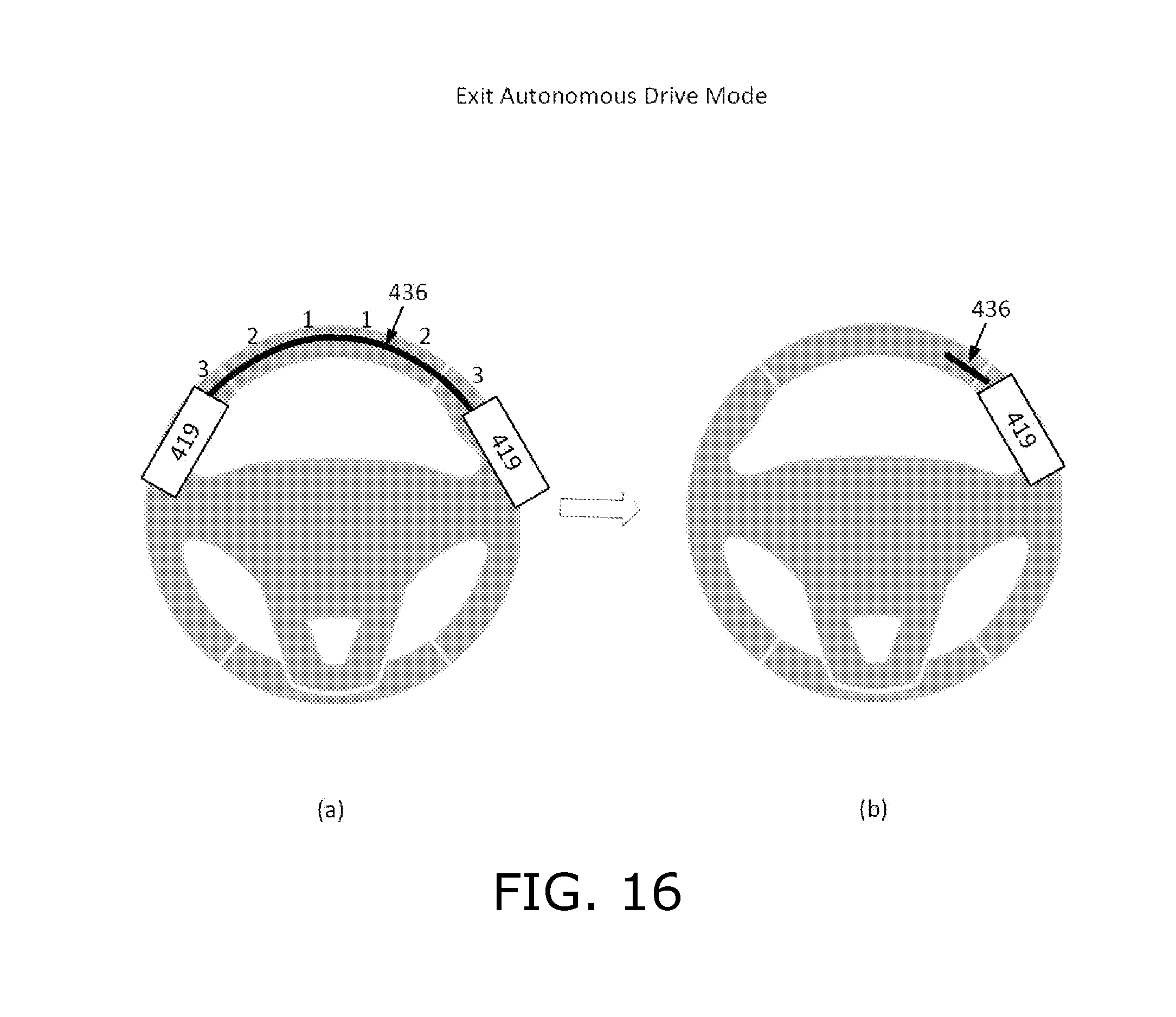
In order to exit Autonomous Drive mode and enter Adaptive Cruise Control mode, the user grabs the steering wheel. Reference is made to FIG. 16, which is a simplified illustration of a gesture and an exemplary user interface for exiting autonomous drive mode, in accordance with an embodiment of the present invention. FIG. 16 shows two hands 419 gripping steering wheel 410, in accordance with an embodiment of the present invention. A series of locations on the steering wheel is then sequentially illuminated to indicate that Autonomous Drive mode is about to be the deactivated. For example, drawing (a) illustrates a sequence of illuminations that begins with (i) the 11:30 and 12:30 clock positions indicated by a 1; followed by (ii) the 10:30 and 1:30 clock positions indicated by 2; followed by (iii) the 9:30 and 2:30 clock positions indicated by 3. When Autonomous Drive mode is deactivated the vehicle enters Adaptive Cruise Control mode, and a portion 436 of steering wheel 410 next to one of the hands 419 gripping the steering wheel is illuminated, as illustrated in drawing (b) of FIG. 16, and as discussed above with reference to FIG. 14.
In both Normal Drive mode and Adaptive Cruise Control mode the user can enable voice activated controls by tapping twice on the outer rim of the steering wheel. When voice-activated controls are enabled the user disables these controls by repeating the same double-tap gesture.
Two voice-activated controls are illustrated in FIG. 13: placing a phone call and enabling volume adjustments. To place a phone call the user says "call" and the name of the person to call, e.g., "call Mom". In order to hang up the call the user performs a swipe gesture along the thumb notch in the steering wheel. To adjust the volume of a call or the stereo system, the user says the word "volume" and then adjusts the volume up or down by swiping clockwise or counter-clockwise along the thumb notch in the steering wheel.
Reference is made to FIG. 17, which is a simplified illustration showing how an incoming call is received, in accordance with an embodiment of the present invention. FIG. 17 shows that when an incoming call is received, the user answers or declines the call by swiping finger 418 clockwise or counter-clockwise along the thumb notch of the steering wheel, e.g. swipe counter-clockwise to accept the call and swipe clockwise to reject the call.
Reference is made to FIG. 18, which is a simplified illustration showing how to hang up a call, in accordance with an embodiment of the present invention. The gesture to hang up a call is a clockwise swipe gesture. However, when a call has been active for a certain amount of time, the system ignores clockwise swipe gestures so that the user does not inadvertently hang up the call. In order to hang up the call, the user first taps the outer rim of the steering wheel, as shown by hand 419, to indicate that the system should respond to the next swipe gesture, followed by a clockwise swipe gesture by finger 418 to hang up the call.
In a city scenario the user interface provides a park assist function that automatically parks the car without the user's intervention. Reference is made to FIG. 19, which is a simplified illustration of a user interface for a park assist function, in accordance with an embodiment of the present invention. When the vehicle is moving at less than 30 km/h, the Park Assist function begins automatically scanning for available parking spaces. In addition, a faded Park Assist icon appears on the HUD, as illustrated in drawing (a) of FIG. 19. As the car further slows down, this icon becomes bolder until the car has stopped moving, as illustrated in drawings (b) and (c) of FIG. 19. The HUD then presents information about available parking spots; e.g. whether the vehicle can fit into that spot. The user performs a double-tap on the outer rim of the steering wheel, as illustrated in drawing (d), by hand 419 to begin the automated parking. To indicate to the Park Assist function that the parking space is on the left side of the car, the user performs this double-tap on of the left half of steering wheel rim. To indicate to the Park Assist function that the parking space is on the right side of the car, the user performs this double-tap on of the right half of steering wheel rim.
In the foregoing specification, the invention has been described with reference to specific exemplary embodiments thereof. It will, however, be evident that various modifications and changes may be made to the specific exemplary embodiments without departing from the broader spirit and scope of the invention. In particular, sensors other than optical sensors may be used to implement the user interface, inter alia capacitive sensors disposed along the circumference of the steering wheel, and cameras that capture images of the steering wheel. Accordingly, the specification and drawings are to be regarded in an illustrative rather than a restrictive sense.
* * * * *
D00000
D00001
D00002
D00003
D00004
D00005
D00006
D00007
D00008
D00009
D00010
D00011
D00012

D00013
D00014

D00015

D00016
D00017
D00018
D00019
XML
uspto.report is an independent third-party trademark research tool that is not affiliated, endorsed, or sponsored by the United States Patent and Trademark Office (USPTO) or any other governmental organization. The information provided by uspto.report is based on publicly available data at the time of writing and is intended for informational purposes only.
While we strive to provide accurate and up-to-date information, we do not guarantee the accuracy, completeness, reliability, or suitability of the information displayed on this site. The use of this site is at your own risk. Any reliance you place on such information is therefore strictly at your own risk.
All official trademark data, including owner information, should be verified by visiting the official USPTO website at www.uspto.gov. This site is not intended to replace professional legal advice and should not be used as a substitute for consulting with a legal professional who is knowledgeable about trademark law.