Tread wear indicator
Serva
U.S. patent number 10,252,580 [Application Number 15/413,452] was granted by the patent office on 2019-04-09 for tread wear indicator. This patent grant is currently assigned to The Goodyear Tire & Rubber Company. The grantee listed for this patent is The Goodyear Tire & Rubber Company. Invention is credited to Jesse Brian Serva.

| United States Patent | 10,252,580 |
| Serva | April 9, 2019 |
Tread wear indicator
Abstract
A tread wear indicator for a tire is provided. The tire includes a pair of sidewalls and a tread, and the tread includes a plurality of tread elements defined by circumferential grooves and lateral grooves. The tread wear indicator is formed in a selected one of the tread elements. The indicator includes a plurality of concentric step elements that descend radially inwardly from a radially outward surface of the selected one of the tread elements. Each step element includes an axially-extending surface that is approximately parallel to and is radially inward of the radially outward surface of the selected one of the tread elements, and a radially-extending surface that extends approximately perpendicular to the axially-extending surface.
| Inventors: | Serva; Jesse Brian (Akron, OH) | ||||||||||
|---|---|---|---|---|---|---|---|---|---|---|---|
| Applicant: |
|
||||||||||
| Assignee: | The Goodyear Tire & Rubber
Company (Akron, OH) |
||||||||||
| Family ID: | 62905540 | ||||||||||
| Appl. No.: | 15/413,452 | ||||||||||
| Filed: | January 24, 2017 |
Prior Publication Data
| Document Identifier | Publication Date | |
|---|---|---|
| US 20180207995 A1 | Jul 26, 2018 | |
| Current U.S. Class: | 1/1 |
| Current CPC Class: | B60C 11/04 (20130101); B60C 11/24 (20130101); B60C 2011/0381 (20130101) |
| Current International Class: | B60C 11/24 (20060101); B60C 11/04 (20060101); B60C 11/03 (20060101) |
References Cited [Referenced By]
U.S. Patent Documents
| 2102784 | December 1937 | Bridges |
| 2287273 | June 1942 | Rabb |
| 2619727 | December 1952 | Krohn, Jr. |
| 2706509 | April 1955 | White |
| 3653422 | April 1972 | French |
| 3814160 | June 1974 | Creasey |
| D250697 | January 1979 | Jordan |
| 4226274 | October 1980 | Awaya et al. |
| 5980668 | November 1999 | Slingluff |
| 6080982 | June 2000 | Cohen |
| 6523586 | February 2003 | Eromaki et al. |
| 6883567 | April 2005 | Shimura |
| 6994133 | February 2006 | Willard, Jr. et al. |
| 7011126 | March 2006 | Heinen |
| 7140410 | November 2006 | Helt et al. |
| 7670123 | March 2010 | Cuny et al. |
| 7784508 | August 2010 | Kemp et al. |
| 8162014 | April 2012 | Mosko et al. |
| 8403012 | March 2013 | Harvey et al. |
| 8584721 | November 2013 | Fujii et al. |
| 8695655 | April 2014 | Cuny et al. |
| 8857252 | October 2014 | Lamb et al. |
| D717727 | November 2014 | Parr et al. |
| D721029 | January 2015 | Sato |
| 8960246 | February 2015 | Shimomura et al. |
| D751497 | March 2016 | Kidney |
| D755705 | May 2016 | Shin |
| D758297 | June 2016 | Kidney |
| D765589 | September 2016 | Hara |
| D786172 | May 2017 | Komazaki et al. |
| 2005/0269003 | December 2005 | Fujii |
| 2006/0037683 | February 2006 | Cuny et al. |
| 2006/0213594 | September 2006 | Kemp |
| 2009/0095388 | April 2009 | Cuny et al. |
| 2011/0079333 | April 2011 | Collette et al. |
| 2011/0126949 | June 2011 | Cuny et al. |
| 2012/0103484 | May 2012 | Ohashi |
| 2013/0186531 | July 2013 | O'Brien |
| 2013/0206291 | August 2013 | Emorine et al. |
| 2014/0060167 | March 2014 | McNaught |
| 2014/0365069 | December 2014 | Orlewski |
| 2015/0328937 | November 2015 | Girard et al. |
| 2015/0343850 | December 2015 | Dorfi et al. |
| 2016/0229232 | August 2016 | Baumgaertel et al. |
| 3627832 | Feb 1988 | DE | |||
| 408833 | Jul 1974 | SU | |||
Other References
|
English translation of SU408833. (Year: 1974). cited by examiner. |
Primary Examiner: Dye; Robert C
Attorney, Agent or Firm: Kennedy; Edward T.
Claims
What is claimed is:
1. A tire including a tread wear indicator, wherein the tire includes a pair of sidewalls and a tread, and the tread includes a plurality of tread elements defined by circumferential grooves and lateral grooves, the tread wear indicator comprising: an indicator being formed in a selected one of the tread elements; the indicator including a plurality of concentric step elements descending radially inwardly from a radially outward surface of the selected one of the tread elements; each step element including an axially-extending surface being approximately parallel to and being radially inward of the radially outward surface of the selected one of the tread elements, and a radially-extending surface extending approximately perpendicular to the axially-extending surface; a laterally-extending wall extending across the indicator in a lateral direction of the tire; and a circumferentially-extending wall extending across the indicator in a circumferential direction of the tire; wherein the laterally-extending wall and the circumferentially-extending wall each comprise two opposing side surfaces.
2. The tire including a tread wear indicator of claim 1, wherein the laterally-extending wall and the circumferentially-extending wall divide the indicator into four quadrants.
3. The tire including a tread wear indicator of claim 1, wherein the indicator is formed in the selected tread element equidistant between circumferential grooves that are disposed on each side of the selected tread element and adjacent the selected tread element, and equidistant between lateral grooves on the selected tread element.
4. The tire including a tread wear indicator of claim 1, wherein the indicator includes at least three step elements.
5. The tire including a tread wear indicator of claim 1, wherein the axially-extending surface of each step element includes a circular shape.
6. The tire including a tread wear indicator of claim 1, wherein the axially-extending surface of each step element is disposed at a height that corresponds to a selected percentage of a recommended tread height.
7. The tire including a tread wear indicator of claim 1, wherein the indicator is formed with an insert that is disposed in a mold which cures the tire.
8. The tire including a tread wear indicator of claim 1, wherein the axially-extending surface of a first one of the step elements is disposed at a height that corresponds to about seventy-five percent of a recommended tread height, the axially-extending surface of a second one of the step elements is disposed at a height that corresponds to about fifty percent of the recommended tread height, and the axially-extending surface of a third one of the step elements is disposed at a height that corresponds to about twenty-five percent of the recommended tread height.
Description
FIELD OF THE INVENTION
The invention relates to pneumatic tires and to tread wear indicators for such tires. More particularly, the invention is directed to a visual tread wear indicator that is economical to form and is easy for a user to read.
BACKGROUND OF THE INVENTION
In the pneumatic tire art, it is known that, as the tread of the tire wears away, the ability to maintain traction may diminish on wet or snow-covered roads. Accordingly, once the tread is worn beyond a certain tread depth, the tire should be replaced to maintain adequate traction.
In order to inform a vehicle user when a tire may need to be replaced due to tread wear, prior art tread wear indicators were developed. For example, some tread wear indicators involved providing features molded in the base of the circumferential grooves of the tire tread. However, such tread wear indicators may undesirably interfere with the flow of water and materials through the groove. In addition, due to their placement in a groove, they may be difficult for a user to see.
Other indicators were developed, which we located in the tread elements of the tires. However, many such prior art indicators have undesirably interfered with tread performance and/or were difficult for a user to see. An additional disadvantage of prior art indicators that were disposed in the tread is that the indicators were of a simple configuration which wore away before the user saw or understood the wear indication.
Still other indicators were developed that involve sensors which measure tire wear and provide an alert or signal to the user as to the wear state of the tire. While such sensors are suitable for their intended purpose, they add to the cost of the tire.
As a result, there is a need in the art for a tread wear indicator for a pneumatic tire that is easy for a user to see, does not interfere with groove or tread element performance, and is economical to form.
SUMMARY OF THE INVENTION
According to an aspect of an exemplary embodiment of the invention, a tread wear indicator is formed in a tire. The tire includes a pair of sidewalls and a tread, and the tread includes a plurality of tread elements defined by circumferential grooves and lateral grooves. The tread wear indicator is formed in a selected one of the tread elements. The indicator includes a plurality of concentric step elements that descend radially inwardly from a radially outward surface of the selected one of the tread elements. Each step element includes an axially-extending surface that is approximately parallel to and is radially inward of the radially outward surface of the selected one of the tread elements, and a radially-extending surface that extends approximately perpendicular to the axially-extending surface.
Definitions
The following definitions are applicable to the present invention.
"Axial" and "axially" mean lines or directions that are parallel to the axis of rotation of the tire.
"Equatorial plane" means the plane perpendicular to the axis of rotation of the tire and passing through the center of the tire tread.
"Groove" means an elongated void area in a tread that may extend circumferentially or laterally about the tread in a straight curved, or zigzag manner.
"Inner" means toward the inside of the tire.
"Lateral" and "laterally" are used to indicate axial directions across the tread of the tire.
"Outer" means toward the outside of the tire.
"Radial" and "radially" are used to mean directions radially toward or away from the axis of rotation of the tire.
"Sipe" means a small elongated opening in the tread that improves traction characteristics.
"Tread" means a molded rubber component which includes that portion of the tire that comes into contact with the road when the tire is normally inflated and under normal load. The tread has a depth conventionally measured from the tread outer surface to the bottom of the deepest groove of the tire.
BRIEF DESCRIPTION OF THE DRAWINGS
The invention will be described by way of example and with reference to the accompanying drawings, in which:
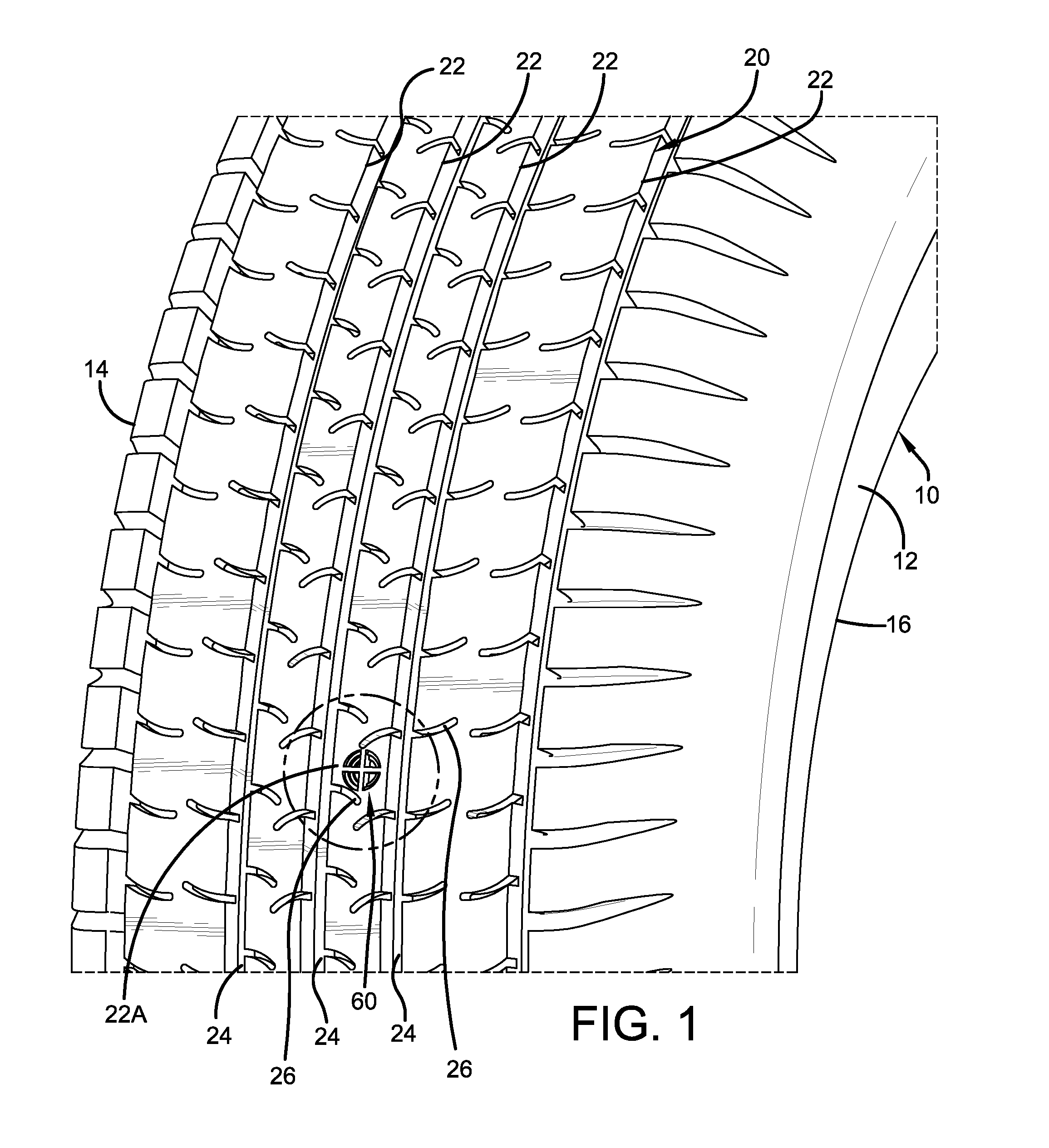
FIG. 1 is a fragmentary perspective view of a tire including an exemplary embodiment of the tread wear indicator of the present invention;
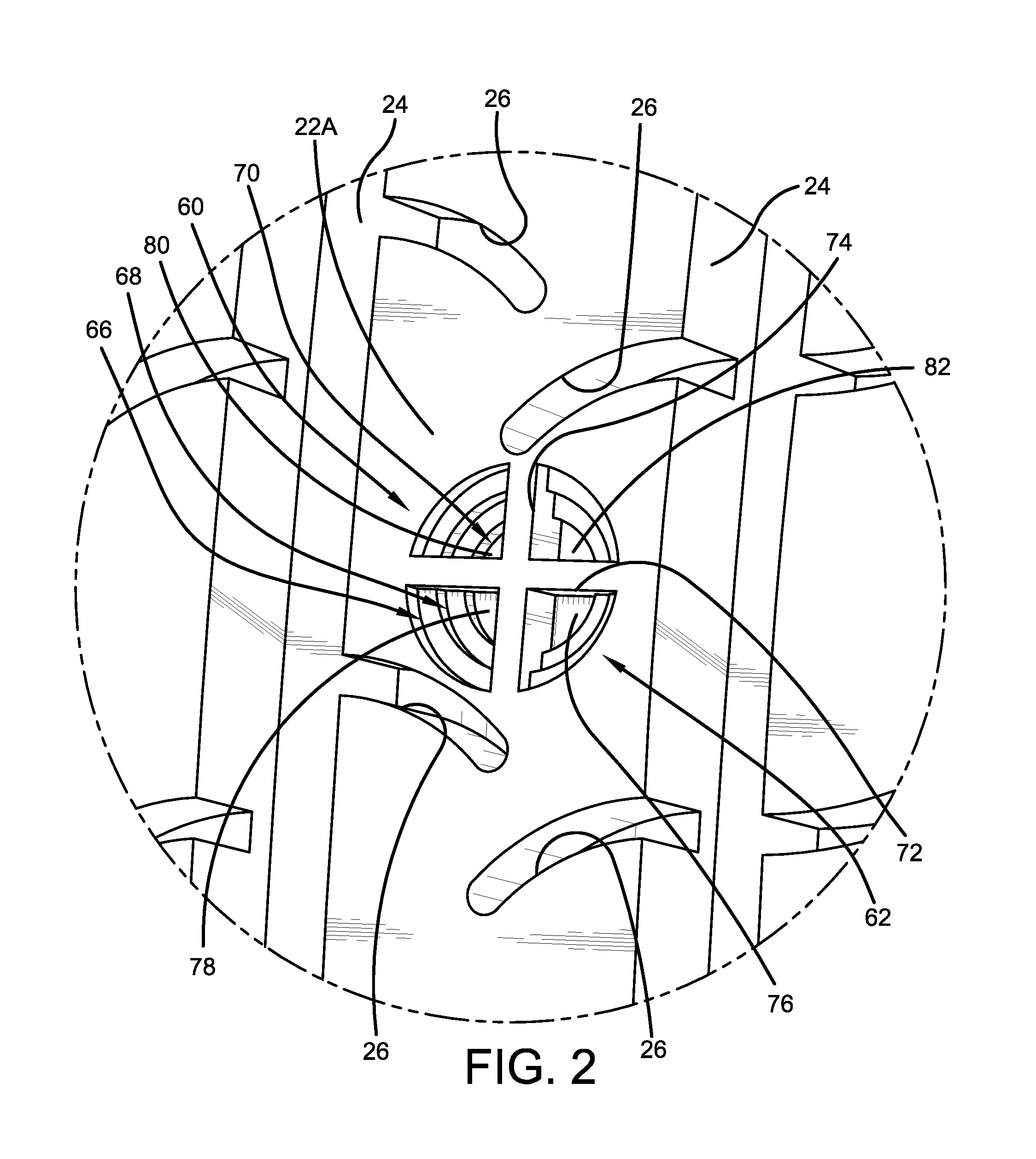
FIG. 2 is an enlarged fragmentary perspective view of the tire and tread wear indicator from the circled area shown in FIG. 1;
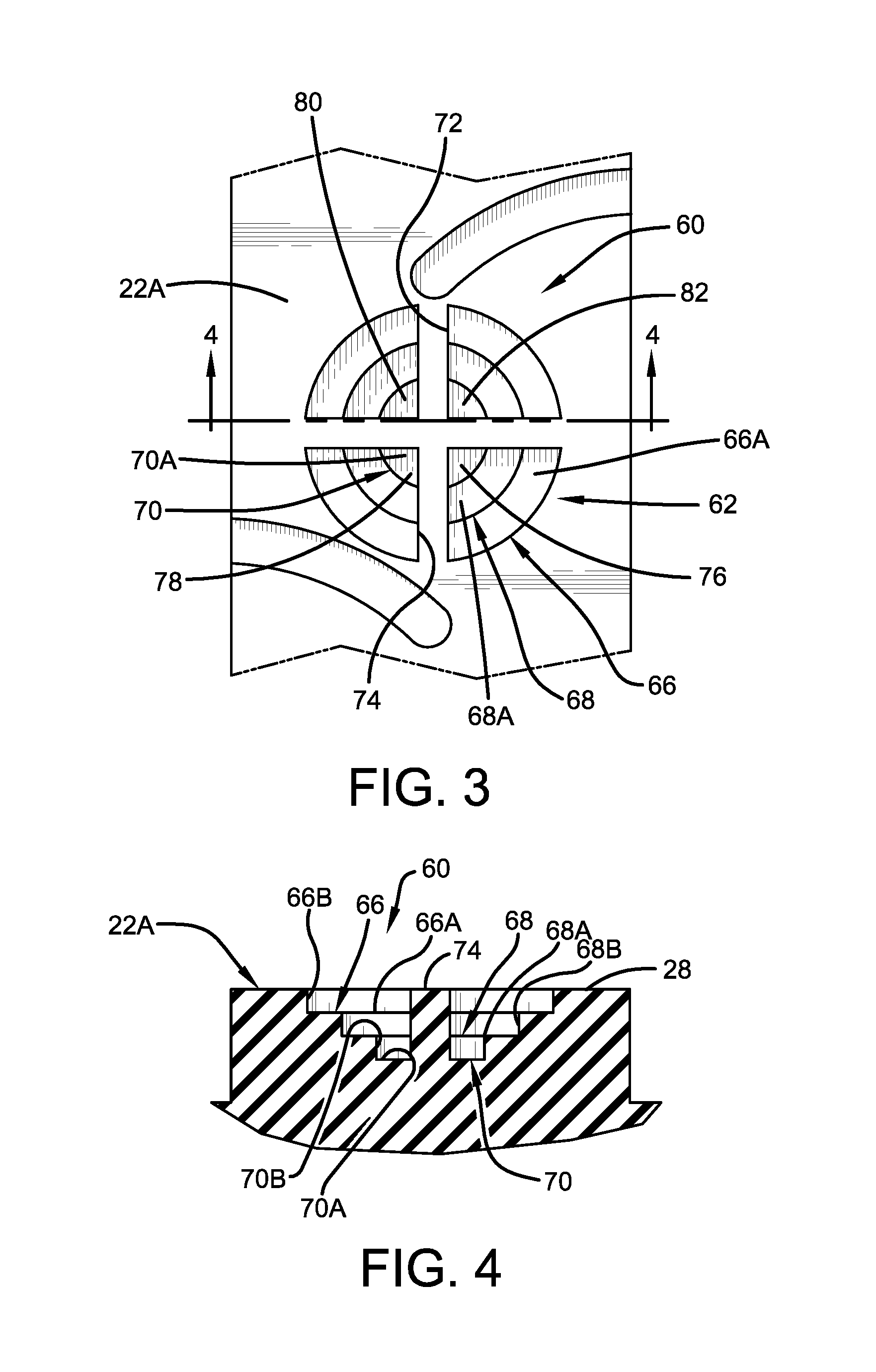
FIG. 3 is a fragmentary plan view of the tire and tread wear indicator shown in FIG. 1;
FIG. 4 is a cross-sectional view of the tire and tread wear indicator taken along line 4-4 in FIG. 3; and
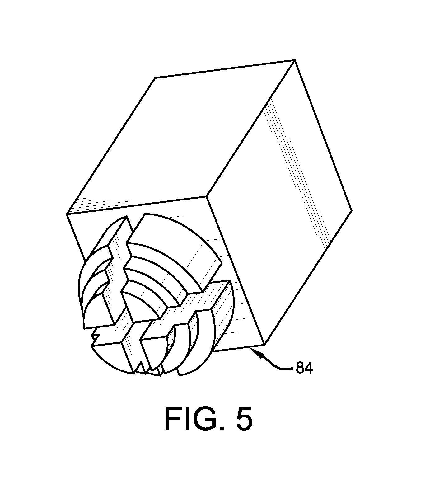
FIG. 5 is a perspective view of a mold insert used to form the tread wear indicator shown in FIG. 1.
Similar numerals refer to similar parts throughout the drawings.
DETAILED DESCRIPTION OF THE INVENTION
Turning first to FIGS. 1 through 4, an exemplary tire is indicated at 10 and includes a pair of sidewalls 12 and 14 extending from respective bead areas 16 (only one shown) to a tread 20. The tread 20 includes a plurality of tread elements 22 that are defined by circumferential grooves 24 and lateral grooves 26. It is to be understood that any tread configuration may be employed with the present invention. Formed in a selected one of the tread elements 22A is an exemplary embodiment of the tread wear indicator of the present invention, indicated generally at 60. It is to be further understood that the tread wear indicator 60 may be formed in any one of the tread elements 22, and that the tire 10 may include more than one tread wear indicator.
The tread wear indicator 60 preferably is formed in the selected tread element 22A equidistant between the circumferential grooves 24 that are disposed on each side of the selected tread element, and equidistant between the lateral grooves 26 on the selected tread element. The tread wear indicator 60 is formed with a configuration that includes a plurality of concentric steps, which preferably are circular. More particularly, a plurality of step elements 62 descends radially inwardly from a radially outward surface 28 of the selected tread element 22A. The tread wear indicator includes at least two elements 62, and preferably three or more elements. As will be described below, each element 62 is similar to the other elements in shape and configuration.
A first or top step 66 includes an axially-extending surface 66A that is approximately parallel to and radially inward of the outward tread surface 28. A radially-extending surface 66B extends from the radially outward tread surface 32 to the axially-extending surface 66A in an approximately perpendicular manner.
A second or middle step 68 includes an axially-extending surface 68A that is parallel to and radially inward of the axially-extending surface 66A of the first step 36. The axially-extending surface 68A of the second step 68 is disposed concentrically inwardly of the axially-extending surface 66A of the first step 66. A radially-extending surface 68B extends approximately perpendicularly from the axially-extending surface 66A of the first step 66 to the second step axially-extending surface 68A.
A third or bottom step 70 includes an axially-extending surface 70A that is parallel to and radially inward of the axially-extending surface 68A of the second step 68. The axially-extending surface 70A of the third step 70 is disposed concentrically inwardly of the axially-extending surface 68A of the second step 68. A radially-extending surface 70B extends approximately perpendicularly from the axially-extending surface 68A of the second step 68 to the third step axially-extending surface 70A.
The height of each one of the step elements 62 is based upon the number of steps and the minimum desired indicator height employed for a particular configuration of the tread wear indicator 60. Preferably, each step 66, 68 and 70 is at a set height which corresponds to a specific percentage of the recommended tread height. More particularly, the new, unworn surface 28 of the tread element 22A is considered to be 100 percent of the recommended tread height. The designers of the tire 10 typically establish a thickness of the tread elements 22 that corresponds to a minimum tread height, which is may be referred to as zero percent of the recommended tread height.
Preferably, the axially-extending surface 66A of the first or top step 66 is at a height that corresponds to 75 percent of the recommended tread height, thus indicating a level or height at which 75 percent of the recommended tread height remains. The axially-extending surface 68A of the second or middle step 68 preferably is at a height that corresponds to 50 percent of the recommended tread height, thus indicating a level or height at which 50 percent of the recommended tread height remains. The axially-extending surface 70A of the third or bottom step 70 preferably is at a height that corresponds to 25 percent of the recommended tread height, thus indicating a level or height at which 25 percent of the recommended tread height remains. Thus, when the tread wear indicator 60 is no longer visible, less than 25 percent of the recommended tread height remains, communicating the need for tire replacement to a user.
The tread wear indicator 60 also includes a laterally-extending wall 72, which extends in a direction across the selected tread element 22A, and a circumferentially-extending wall 74, which extends in the circumferential direction of the tire 10. The laterally-extending wall 72 and the circumferentially-extending wall 74 extend perpendicular to one another across the indicator 60 and divide the indicator into four quadrants 76, 78, 80 and 82.
By being divided into quadrants 76, 78, 80 and 82, the tread wear indicator 60 enables checking of vehicle alignment through an inspection of the wear pattern of the tire 10. For example, comparison of quadrant 76 to 82, or of quadrant 78 to 80, indicates the uniformity of wear of the tire 10 in the forward and reverse rotational directions, which is referred to as "heel-toe tread wear". Comparison of quadrant 76 to 78, or of quadrant 80 to 82, indicates the uniformity of wear of the tire 10 in a lateral direction across the tread elements 22, which is referred to as "lateral block wear". In this manner, a user can view quadrants 76, 78, 80 and 82 of the tread wear indicator 60 to easily determine heel-toe tread wear and/or lateral block wear, which in turn provides an indication of the uniformity of tire wear and thus the vehicle alignment.
By being located in the selected tread element 22A, the tread wear indicator 60 is easy for a user to see, does not interfere with the performance of the grooves 24 and 26 or the tread 20, and is economical to form.
Turning to FIG. 5, the tread wear indicator 60 preferably is formed in the tire 10 when the tire is cured. As is known in the art, the tire 10 is cured in a mold (not shown). During curing, the tread 20 is formed. To form the tread wear indicator 60, a die insert 84 is formed with the above-described features of the tread wear indicator. The die insert 84 is disposed in a corresponding opening formed in the tire curing mold, and when the tread 20 is formed on the tire 10 during curing, the tread wear indicator 60 is also formed. The die insert 84 may be 3D printed, cast or fabricated, and may be formed of any suitable mold material, including steel, aluminum and alloys thereof.
The present invention also includes a method of forming a tread wear indicator 60 in a tire 10 and a method of using a tread wear indicator 60 in a tire 10. Each method includes steps in accordance with the description that is presented above and shown in FIGS. 1 through 5.
It is to be understood that the structure of the above-described tread wear indicator may be altered or rearranged, or components or steps known to those skilled in the art omitted or added, without affecting the overall concept or operation of the invention. For example, heights for the step elements other than those described above may be employed without affecting the overall concept or operation of the invention.
The invention has been described with reference to a preferred embodiment. Potential modifications and alterations will occur to others upon a reading and understanding of this description. It is to be understood that all such modifications and alterations are included in the scope of the invention as set forth in the appended claims, or the equivalents thereof.
* * * * *
D00000
D00001
D00002
D00003
D00004
XML
uspto.report is an independent third-party trademark research tool that is not affiliated, endorsed, or sponsored by the United States Patent and Trademark Office (USPTO) or any other governmental organization. The information provided by uspto.report is based on publicly available data at the time of writing and is intended for informational purposes only.
While we strive to provide accurate and up-to-date information, we do not guarantee the accuracy, completeness, reliability, or suitability of the information displayed on this site. The use of this site is at your own risk. Any reliance you place on such information is therefore strictly at your own risk.
All official trademark data, including owner information, should be verified by visiting the official USPTO website at www.uspto.gov. This site is not intended to replace professional legal advice and should not be used as a substitute for consulting with a legal professional who is knowledgeable about trademark law.