Self-aligning radiopaque ring
McNiven , et al.
U.S. patent number 10,238,494 [Application Number 14/754,274] was granted by the patent office on 2019-03-26 for self-aligning radiopaque ring. This patent grant is currently assigned to EVALVE, INC.. The grantee listed for this patent is Evalve, Inc.. Invention is credited to Herminia C. Heflin, Stephanie A. Kozuma, Sean A. McNiven.


| United States Patent | 10,238,494 |
| McNiven , et al. | March 26, 2019 |
Self-aligning radiopaque ring
Abstract
An intravascular device configured to be recaptured within a guide catheter has a ring located at the distal end of a delivery catheter. The ring has an outer diameter greater than that of the delivery catheter and a sloped guide surface near the outer edge of the ring to urge the ring and delivery catheter toward a radially centered position within the guide catheter.
| Inventors: | McNiven; Sean A. (Menlo Park, CA), Heflin; Herminia C. (Pleasanton, CA), Kozuma; Stephanie A. (San Mateo, CA) | ||||||||||
|---|---|---|---|---|---|---|---|---|---|---|---|
| Applicant: |
|
||||||||||
| Assignee: | EVALVE, INC. (Santa Clara,
CA) |
||||||||||
| Family ID: | 56118031 | ||||||||||
| Appl. No.: | 14/754,274 | ||||||||||
| Filed: | June 29, 2015 |
Prior Publication Data
| Document Identifier | Publication Date | |
|---|---|---|
| US 20160374811 A1 | Dec 29, 2016 | |
| Current U.S. Class: | 1/1 |
| Current CPC Class: | A61F 2/2466 (20130101); A61F 2/246 (20130101); A61B 90/39 (20160201); A61B 2017/00238 (20130101); A61B 2090/3966 (20160201) |
| Current International Class: | A61F 2/24 (20060101); A61B 90/00 (20160101); A61B 17/00 (20060101) |
References Cited [Referenced By]
U.S. Patent Documents
| 2097018 | October 1937 | Chamberlain |
| 2108206 | February 1938 | Meeker |
| 3296668 | January 1967 | Aiken |
| 3378010 | April 1968 | Codling et al. |
| 3557780 | January 1971 | Sato |
| 3675639 | July 1972 | Cimber |
| 3874388 | April 1975 | King et al. |
| 4007743 | February 1977 | Blake |
| 4064881 | December 1977 | Meredith |
| 4091815 | May 1978 | Larsen |
| 4112951 | September 1978 | Hulka et al. |
| 4235238 | November 1980 | Ogiu et al. |
| 4297749 | November 1981 | Davis et al. |
| 4425908 | January 1984 | Simon |
| 4458682 | July 1984 | Cerwin |
| 4487205 | December 1984 | Di Giovanni et al. |
| 4498476 | February 1985 | Cerwin et al. |
| 4510934 | April 1985 | Batra |
| 4531522 | July 1985 | Bedi et al. |
| 4578061 | March 1986 | Lemelson |
| 4641366 | February 1987 | Yokoyama et al. |
| 4686965 | August 1987 | Bonnet et al. |
| 4777951 | October 1988 | Cribier et al. |
| 4809695 | March 1989 | Gwathmey et al. |
| 4896986 | January 1990 | Terayama |
| 4944295 | July 1990 | Gwathmey et al. |
| 4969890 | November 1990 | Sugita et al. |
| 5015249 | May 1991 | Nakao et al. |
| 5019096 | May 1991 | Fox, Jr. et al. |
| 5042161 | August 1991 | Hodge |
| 5042707 | August 1991 | Taheri |
| 5047041 | September 1991 | Samuels |
| 5049153 | September 1991 | Nakao et al. |
| 5061277 | October 1991 | Carpentier et al. |
| 5069679 | December 1991 | Taheri |
| 5108368 | April 1992 | Hammerslag et al. |
| 5125758 | June 1992 | DeWan |
| 5171252 | December 1992 | Friedland |
| 5171259 | December 1992 | Inoue |
| 5190554 | March 1993 | Coddington et al. |
| 5195968 | March 1993 | Lundquist et al. |
| 5209756 | May 1993 | Seedhom et al. |
| 5226429 | July 1993 | Kuzmak |
| 5226911 | July 1993 | Chee et al. |
| 5234437 | August 1993 | Sepetka |
| 5236450 | August 1993 | Scott |
| 5242456 | September 1993 | Nash et al. |
| 5250071 | October 1993 | Palermo |
| 5251611 | October 1993 | Zehel et al. |
| 5254130 | October 1993 | Poncet et al. |
| 5261916 | November 1993 | Engelson |
| 5263939 | November 1993 | Wortrich |
| 5271381 | December 1993 | Ailinger et al. |
| 5275578 | January 1994 | Adams |
| 5282845 | February 1994 | Bush et al. |
| 5304131 | April 1994 | Paskar |
| 5306283 | April 1994 | Conners |
| 5306286 | April 1994 | Stack et al. |
| 5312415 | May 1994 | Palermo |
| 5314424 | May 1994 | Nicholas |
| 5318525 | June 1994 | West et al. |
| 5320632 | June 1994 | Heidmueller |
| 5325845 | July 1994 | Adair |
| 5330442 | July 1994 | Green et al. |
| 5342393 | August 1994 | Stack |
| 5350397 | September 1994 | Palermo et al. |
| 5350399 | September 1994 | Erlebacher et al. |
| 5359994 | November 1994 | Krauter et al. |
| 5368564 | November 1994 | Savage |
| 5368601 | November 1994 | Sauer et al. |
| 5383886 | January 1995 | Kensey et al. |
| 5391182 | February 1995 | Chin |
| 5403312 | April 1995 | Yates et al. |
| 5403326 | April 1995 | Harrison et al. |
| 5405402 | April 1995 | Dye |
| 5417699 | May 1995 | Klein et al. |
| 5417700 | May 1995 | Egan |
| 5423857 | June 1995 | Rosenman et al. |
| 5423858 | June 1995 | Bolanos et al. |
| 5423882 | June 1995 | Jackman et al. |
| 5431666 | July 1995 | Sauer et al. |
| 5437551 | August 1995 | Chalifoux |
| 5437681 | August 1995 | Meade et al. |
| 5447966 | September 1995 | Hermes et al. |
| 5450860 | September 1995 | O'Connor |
| 5456400 | October 1995 | Shichman et al. |
| 5456684 | October 1995 | Schmidt et al. |
| 5462527 | October 1995 | Stevens-Wright et al. |
| 5464394 | November 1995 | Miller et al. |
| 5472044 | December 1995 | Hall et al. |
| 5476470 | December 1995 | Fitzgibbons, Jr. |
| 5477856 | December 1995 | Lundquist |
| 5478309 | December 1995 | Sweezer et al. |
| 5478353 | December 1995 | Yoon |
| 5487746 | January 1996 | Yu et al. |
| 5489296 | February 1996 | Love |
| 5496332 | March 1996 | Sierra et al. |
| 5507725 | April 1996 | Savage et al. |
| 5507755 | April 1996 | Gresl et al. |
| 5507757 | April 1996 | Sauer et al. |
| 5520701 | May 1996 | Lerch |
| 5522873 | June 1996 | Jackman et al. |
| 5527313 | June 1996 | Scott et al. |
| 5527321 | June 1996 | Hinchliffe |
| 5527322 | June 1996 | Klein et al. |
| 5536251 | July 1996 | Evard et al. |
| 5540705 | July 1996 | Meade et al. |
| 5542949 | August 1996 | Yoon |
| 5562678 | October 1996 | Booker |
| 5569274 | October 1996 | Rapacki et al. |
| 5571085 | November 1996 | Accisano, III |
| 5571137 | November 1996 | Marlow et al. |
| 5571215 | November 1996 | Sterman et al. |
| 5575802 | November 1996 | McQuilkin et al. |
| 5582611 | December 1996 | Tsuruta et al. |
| 5593424 | January 1997 | Northrup, III |
| 5593435 | January 1997 | Carpentier et al. |
| 5609598 | March 1997 | Laufer et al. |
| 5618306 | April 1997 | Roth et al. |
| 5620452 | April 1997 | Yoon |
| 5620461 | April 1997 | Mugs Van De Moer et al. |
| 5626588 | May 1997 | Sauer et al. |
| 5630832 | May 1997 | Giordano et al. |
| 5634932 | June 1997 | Schmidt |
| 5636634 | June 1997 | Kordis et al. |
| 5639277 | June 1997 | Mariant et al. |
| 5640955 | June 1997 | Ockuly et al. |
| 5649937 | July 1997 | Bito et al. |
| 5662606 | September 1997 | Cimino et al. |
| 5662681 | September 1997 | Nash et al. |
| 5669917 | September 1997 | Sauer et al. |
| 5690671 | November 1997 | McGurk et al. |
| 5695504 | December 1997 | Gifford, III et al. |
| 5695505 | December 1997 | Yoon |
| 5702825 | December 1997 | Keita et al. |
| 5706824 | January 1998 | Whittier |
| 5709707 | January 1998 | Lock et al. |
| 5713910 | February 1998 | Gordon et al. |
| 5713911 | February 1998 | Racene et al. |
| 5715817 | February 1998 | Stevens-Wright et al. |
| 5716367 | February 1998 | Koike et al. |
| 5718714 | February 1998 | Livneh |
| 5719725 | February 1998 | Nakao |
| 5722421 | March 1998 | Francese et al. |
| 5725542 | March 1998 | Yoon |
| 5725556 | March 1998 | Moser et al. |
| 5738649 | April 1998 | Macoviak |
| 5741280 | April 1998 | Fleenor |
| 5741286 | April 1998 | Recuset |
| 5749828 | May 1998 | Solomon et al. |
| 5759193 | June 1998 | Burbank et al. |
| 5769863 | June 1998 | Garrison |
| 5772578 | June 1998 | Heimberger et al. |
| 5782845 | July 1998 | Shewchuk |
| 5797927 | August 1998 | Yoon |
| 5810847 | September 1998 | Laufer et al. |
| 5810849 | September 1998 | Kontos |
| 5810853 | September 1998 | Yoon |
| 5810876 | September 1998 | Kelleher |
| 5814029 | September 1998 | Hassett |
| 5820592 | October 1998 | Hammerslag |
| 5820631 | October 1998 | Nobles |
| 5823955 | October 1998 | Kuck et al. |
| 5824065 | October 1998 | Gross |
| 5827237 | October 1998 | Macoviak et al. |
| 5833671 | November 1998 | Macoviak et al. |
| 5836955 | November 1998 | Buelna et al. |
| 5843031 | December 1998 | Hermann et al. |
| 5849019 | December 1998 | Yoon |
| 5853422 | December 1998 | Huebsch et al. |
| 5855271 | January 1999 | Eubanks et al. |
| 5855590 | January 1999 | Malecki et al. |
| 5860990 | January 1999 | Nobles et al. |
| 5861003 | January 1999 | Latson et al. |
| 5868733 | February 1999 | Ockuly et al. |
| 5871493 | February 1999 | Sjostrom et al. |
| 5876399 | March 1999 | Chia et al. |
| 5879307 | March 1999 | Chio et al. |
| 5885271 | March 1999 | Hamilton et al. |
| 5891160 | April 1999 | Williamson, IV et al. |
| 5902290 | May 1999 | Peacock, III et al. |
| 5916147 | June 1999 | Boury |
| 5928224 | July 1999 | Laufer |
| 5944733 | August 1999 | Engelson |
| 5947363 | September 1999 | Bolduc et al. |
| 5954732 | September 1999 | Hart et al. |
| 5957949 | September 1999 | Leonhard et al. |
| 5964717 | October 1999 | Gottlieb et al. |
| 5972020 | October 1999 | Carpentier et al. |
| 5972030 | October 1999 | Garrison et al. |
| 5980455 | November 1999 | Daniel et al. |
| 5989284 | November 1999 | Laufer |
| 5993470 | November 1999 | Yoon |
| 6015417 | January 2000 | Reynolds, Jr. |
| 6019722 | February 2000 | Spence et al. |
| 6022360 | February 2000 | Reimels et al. |
| 6033378 | March 2000 | Lundquist et al. |
| 6036699 | March 2000 | Andreas et al. |
| 6048351 | April 2000 | Gordon et al. |
| 6056769 | May 2000 | Epstein et al. |
| 6059757 | May 2000 | Macoviak et al. |
| 6060628 | May 2000 | Aoyama et al. |
| 6060629 | May 2000 | Pham et al. |
| 6063106 | May 2000 | Gibson |
| 6066146 | May 2000 | Carroll et al. |
| 6068628 | May 2000 | Fenton et al. |
| 6068629 | May 2000 | Haissaguerre et al. |
| 6077214 | June 2000 | Mortier et al. |
| 6086600 | July 2000 | Kortenbach |
| 6088889 | July 2000 | Luther et al. |
| 6099505 | August 2000 | Ryan et al. |
| 6099553 | August 2000 | Hart et al. |
| 6110145 | August 2000 | Macoviak |
| 6117144 | September 2000 | Nobles et al. |
| 6117159 | September 2000 | Huebsch et al. |
| 6123699 | September 2000 | Webster, Jr. |
| 6126658 | October 2000 | Baker |
| 6132447 | October 2000 | Dorsey |
| 6136010 | October 2000 | Modesitt et al. |
| 6139214 | October 2000 | Zirps et al. |
| 6143024 | November 2000 | Campbell et al. |
| 6159240 | December 2000 | Sparer et al. |
| 6162233 | December 2000 | Williamson, IV et al. |
| 6165164 | December 2000 | Hill et al. |
| 6165183 | December 2000 | Kuehn et al. |
| 6165204 | December 2000 | Levinson et al. |
| 6168614 | January 2001 | Andersen et al. |
| 6171320 | January 2001 | Monassevitch |
| 6182664 | February 2001 | Cosgrove |
| 6187003 | February 2001 | Buysse et al. |
| 6190408 | February 2001 | Melvin |
| 6203531 | March 2001 | Ockuly et al. |
| 6203553 | March 2001 | Robertson et al. |
| 6206893 | March 2001 | Klein et al. |
| 6206907 | March 2001 | Marino et al. |
| 6210419 | April 2001 | Mayenberger et al. |
| 6210432 | April 2001 | Solem et al. |
| 6245079 | June 2001 | Nobles et al. |
| 6267746 | July 2001 | Bumbalough |
| 6267781 | July 2001 | Tu |
| 6269819 | August 2001 | Oz et al. |
| 6277555 | August 2001 | Duran et al. |
| 6283127 | September 2001 | Sterman et al. |
| 6283962 | September 2001 | Tu et al. |
| 6299637 | October 2001 | Shaolian et al. |
| 6306133 | October 2001 | Tu et al. |
| 6312447 | November 2001 | Grimes |
| 6319250 | November 2001 | Falwell et al. |
| 6322559 | November 2001 | Daulton et al. |
| 6332893 | December 2001 | Mortier et al. |
| 6350281 | February 2002 | Rhee |
| 6352708 | March 2002 | Duran et al. |
| 6355030 | March 2002 | Aldrich et al. |
| 6358277 | March 2002 | Duran |
| 6368326 | April 2002 | Dakin et al. |
| 6387104 | May 2002 | Pugsley, Jr. et al. |
| 6402780 | June 2002 | Williamson et al. |
| 6402781 | June 2002 | Langberg et al. |
| 6406420 | June 2002 | McCarthy et al. |
| 6419669 | July 2002 | Frazier et al. |
| 6461366 | October 2002 | Seguin |
| 6464707 | October 2002 | Bjerken |
| 6482224 | November 2002 | Michler et al. |
| 6485489 | November 2002 | Teirstein et al. |
| 6508828 | January 2003 | Akerfeldt et al. |
| 6533796 | March 2003 | Sauer et al. |
| 6537314 | March 2003 | Langberg et al. |
| 6540755 | April 2003 | Ockuly et al. |
| 6551331 | April 2003 | Nobles et al. |
| 6562037 | May 2003 | Paton et al. |
| 6562052 | May 2003 | Nobles et al. |
| 6575971 | June 2003 | Hauck et al. |
| 6585761 | July 2003 | Taheri |
| 6599311 | July 2003 | Biggs et al. |
| 6616684 | September 2003 | Vidlund et al. |
| 6619291 | September 2003 | Hlavka et al. |
| 6626899 | September 2003 | Houser et al. |
| 6626930 | September 2003 | Allen et al. |
| 6629534 | October 2003 | St. Goar et al. |
| 6641592 | November 2003 | Sauer et al. |
| 6656221 | December 2003 | Taylor et al. |
| 6669687 | December 2003 | Saadat |
| 6685648 | February 2004 | Flaherty et al. |
| 6689164 | February 2004 | Seguin |
| 6695866 | February 2004 | Kuehn et al. |
| 6701929 | March 2004 | Hussein |
| 6702825 | March 2004 | Frazier et al. |
| 6702826 | March 2004 | Liddicoat et al. |
| 6709382 | March 2004 | Homer |
| 6709456 | March 2004 | Langberg et al. |
| 6718985 | April 2004 | Hlavka et al. |
| 6719767 | April 2004 | Kimblad |
| 6723038 | April 2004 | Schroeder et al. |
| 6726716 | April 2004 | Marquez |
| 6740107 | May 2004 | Loeb et al. |
| 6746471 | June 2004 | Mortier et al. |
| 6752813 | June 2004 | Goldfarb et al. |
| 6755777 | June 2004 | Schweich et al. |
| 6764510 | July 2004 | Vidlund et al. |
| 6767349 | July 2004 | Ouchi |
| 6770083 | August 2004 | Seguin |
| 6797001 | September 2004 | Mathis et al. |
| 6797002 | September 2004 | Spence et al. |
| 6860179 | March 2005 | Hopper et al. |
| 6875224 | April 2005 | Grimes |
| 6926715 | August 2005 | Hauck et al. |
| 6945978 | September 2005 | Hyde |
| 6949122 | September 2005 | Adams et al. |
| 6966914 | November 2005 | Abe |
| 6986775 | January 2006 | Morales et al. |
| 7004970 | February 2006 | Cauthen, III et al. |
| 7011669 | March 2006 | Kimblad |
| 7048754 | May 2006 | Martin et al. |
| 7112207 | September 2006 | Allen et al. |
| 7226467 | June 2007 | Lucatero et al. |
| 7288097 | October 2007 | Seguin |
| 7381210 | June 2008 | Zarbatany et al. |
| 7464712 | December 2008 | Oz et al. |
| 7497822 | March 2009 | Kugler et al. |
| 7533790 | May 2009 | Knodel et al. |
| 7563267 | July 2009 | Goldfarb et al. |
| 7563273 | July 2009 | Goldfarb et al. |
| 7604646 | October 2009 | Goldfarb et al. |
| 7635329 | December 2009 | Goldfarb et al. |
| 7651502 | January 2010 | Jackson |
| 7655015 | February 2010 | Goldfarb et al. |
| 7666204 | February 2010 | Thornton et al. |
| 8216256 | July 2012 | Raschdorf, Jr. et al. |
| D668334 | October 2012 | Makowski et al. |
| D740414 | October 2015 | Katsura |
| D809139 | January 2018 | Marsot et al. |
| 2001/0004715 | June 2001 | Duran et al. |
| 2001/0005787 | June 2001 | Oz et al. |
| 2001/0007067 | July 2001 | Kurfess et al. |
| 2001/0010005 | July 2001 | Kammerer et al. |
| 2001/0018611 | August 2001 | Solem et al. |
| 2001/0022872 | September 2001 | Marui |
| 2001/0037084 | November 2001 | Nardeo |
| 2001/0039411 | November 2001 | Johansson et al. |
| 2001/0044568 | November 2001 | Langberg et al. |
| 2002/0013571 | January 2002 | Goldfarb et al. |
| 2002/0022848 | February 2002 | Garrison et al. |
| 2002/0026233 | February 2002 | Shaknovich |
| 2002/0035361 | March 2002 | Houser et al. |
| 2002/0035381 | March 2002 | Bardy et al. |
| 2002/0042651 | April 2002 | Liddicoat et al. |
| 2002/0055767 | May 2002 | Forde et al. |
| 2002/0055774 | May 2002 | Liddicoat |
| 2002/0055775 | May 2002 | Carpentier et al. |
| 2002/0058910 | May 2002 | Hermann et al. |
| 2002/0058995 | May 2002 | Stevens |
| 2002/0077687 | June 2002 | Ahn |
| 2002/0087148 | July 2002 | Brock et al. |
| 2002/0087169 | July 2002 | Brock et al. |
| 2002/0087173 | July 2002 | Alferness et al. |
| 2002/0103532 | August 2002 | Langberg et al. |
| 2002/0107534 | August 2002 | Schaefer et al. |
| 2002/0147456 | October 2002 | Diduch et al. |
| 2002/0156526 | October 2002 | Hlavka et al. |
| 2002/0158528 | October 2002 | Tsuzaki et al. |
| 2002/0161378 | October 2002 | Downing |
| 2002/0169360 | November 2002 | Taylor et al. |
| 2002/0183766 | December 2002 | Seguin |
| 2002/0183787 | December 2002 | Wahr et al. |
| 2002/0183835 | December 2002 | Taylor et al. |
| 2003/0005797 | January 2003 | Hopper et al. |
| 2003/0045778 | March 2003 | Ohline et al. |
| 2003/0050693 | March 2003 | Quijano et al. |
| 2003/0069570 | April 2003 | Witzel et al. |
| 2003/0069593 | April 2003 | Tremulis et al. |
| 2003/0069636 | April 2003 | Solem et al. |
| 2003/0074012 | April 2003 | Nguyen et al. |
| 2003/0078654 | April 2003 | Taylor et al. |
| 2003/0083742 | May 2003 | Spence et al. |
| 2003/0105519 | June 2003 | Fasol et al. |
| 2003/0105520 | June 2003 | Alferness et al. |
| 2003/0120340 | June 2003 | Lisk et al. |
| 2003/0120341 | June 2003 | Shennib et al. |
| 2003/0130669 | July 2003 | Damarati |
| 2003/0130730 | July 2003 | Cohn et al. |
| 2003/0144697 | July 2003 | Mathis et al. |
| 2003/0167071 | September 2003 | Martin et al. |
| 2003/0171776 | September 2003 | Adams et al. |
| 2003/0181855 | September 2003 | Simpson et al. |
| 2003/0187467 | October 2003 | Schreck |
| 2003/0195562 | October 2003 | Collier et al. |
| 2003/0208231 | November 2003 | Williamson, IV et al. |
| 2003/0229395 | December 2003 | Cox |
| 2003/0233038 | December 2003 | Hassett |
| 2004/0002719 | January 2004 | Oz et al. |
| 2004/0003819 | January 2004 | St. Goar et al. |
| 2004/0019377 | January 2004 | Taylor et al. |
| 2004/0019378 | January 2004 | Hlavka et al. |
| 2004/0024414 | February 2004 | Downing |
| 2004/0030382 | February 2004 | St. Goar et al. |
| 2004/0039442 | February 2004 | St. Goar et al. |
| 2004/0039443 | February 2004 | Solem et al. |
| 2004/0044350 | March 2004 | Martin et al. |
| 2004/0044365 | March 2004 | Bachman |
| 2004/0049211 | March 2004 | Tremulis et al. |
| 2004/0073302 | April 2004 | Rourke et al. |
| 2004/0078053 | April 2004 | Berg et al. |
| 2004/0087975 | May 2004 | Lucatero et al. |
| 2004/0088047 | May 2004 | Spence et al. |
| 2004/0092962 | May 2004 | Thorton et al. |
| 2004/0097878 | May 2004 | Anderson et al. |
| 2004/0097979 | May 2004 | Svanidze et al. |
| 2004/0106989 | June 2004 | Wilson et al. |
| 2004/0111099 | June 2004 | Nguyen et al. |
| 2004/0122448 | June 2004 | Levine |
| 2004/0127981 | July 2004 | Randert et al. |
| 2004/0127982 | July 2004 | MacHold et al. |
| 2004/0127983 | July 2004 | Mortier et al. |
| 2004/0133062 | July 2004 | Pai et al. |
| 2004/0133063 | July 2004 | McCarthy et al. |
| 2004/0133082 | July 2004 | Abraham-Fuchs et al. |
| 2004/0133192 | July 2004 | Houser et al. |
| 2004/0133220 | July 2004 | Lashinski et al. |
| 2004/0133240 | July 2004 | Adams et al. |
| 2004/0133273 | July 2004 | Cox |
| 2004/0138529 | July 2004 | Wiltshire et al. |
| 2004/0138675 | July 2004 | Crabtree |
| 2004/0138744 | July 2004 | Lashinski et al. |
| 2004/0138745 | July 2004 | Macoviak et al. |
| 2004/0148021 | July 2004 | Cartledge et al. |
| 2004/0152847 | August 2004 | Emri et al. |
| 2004/0152947 | August 2004 | Schroeder et al. |
| 2004/0153144 | August 2004 | Seguin |
| 2004/0158123 | August 2004 | Jayaraman |
| 2004/0162610 | August 2004 | Laiska et al. |
| 2004/0167539 | August 2004 | Kuehn et al. |
| 2004/0186486 | September 2004 | Roue et al. |
| 2004/0186566 | September 2004 | Hindrichs et al. |
| 2004/0193191 | September 2004 | Starksen et al. |
| 2004/0215339 | October 2004 | Drasler et al. |
| 2004/0220593 | November 2004 | Greenhalgh |
| 2004/0220657 | November 2004 | Nieminen et al. |
| 2004/0225300 | November 2004 | Goldfarb et al. |
| 2004/0236354 | November 2004 | Seguin |
| 2004/0243227 | December 2004 | Starksen et al. |
| 2004/0243229 | December 2004 | Vidlund et al. |
| 2004/0249452 | December 2004 | Adams et al. |
| 2004/0249453 | December 2004 | Cartledge et al. |
| 2004/0260393 | December 2004 | Randert et al. |
| 2005/0004583 | January 2005 | Oz et al. |
| 2005/0004665 | January 2005 | Aklog |
| 2005/0004668 | January 2005 | Aklog et al. |
| 2005/0006432 | January 2005 | Racenet et al. |
| 2005/0021056 | January 2005 | St. Goer et al. |
| 2005/0021057 | January 2005 | St. Goer et al. |
| 2005/0021058 | January 2005 | Negro |
| 2005/0033446 | February 2005 | Deem et al. |
| 2005/0038508 | February 2005 | Gabbay |
| 2005/0049698 | March 2005 | Bolling et al. |
| 2005/0055089 | March 2005 | Macoviak et al. |
| 2005/0059351 | March 2005 | Cauwels et al. |
| 2005/0149014 | July 2005 | Hauck et al. |
| 2005/0159810 | July 2005 | Filsoufi |
| 2005/0197694 | September 2005 | Pai et al. |
| 2005/0197695 | September 2005 | Stacchino et al. |
| 2005/0216039 | September 2005 | Lederman |
| 2005/0228422 | October 2005 | Machold et al. |
| 2005/0228495 | October 2005 | Macoviak |
| 2005/0251001 | November 2005 | Hassett |
| 2005/0267493 | December 2005 | Schreck et al. |
| 2005/0273160 | December 2005 | Lashinski et al. |
| 2005/0287493 | December 2005 | Novak et al. |
| 2006/0004247 | January 2006 | Kute et al. |
| 2006/0009715 | January 2006 | Khairkhahan et al. |
| 2006/0015003 | January 2006 | Moaddes et al. |
| 2006/0020275 | January 2006 | Goldfarb et al. |
| 2006/0030866 | February 2006 | Schreck |
| 2006/0030867 | February 2006 | Zadno |
| 2006/0030885 | February 2006 | Hyde |
| 2006/0058871 | March 2006 | Zakay et al. |
| 2006/0064115 | March 2006 | Allen et al. |
| 2006/0064116 | March 2006 | Allen et al. |
| 2006/0064118 | March 2006 | Kimblad |
| 2006/0089671 | April 2006 | Goldfarb et al. |
| 2006/0089711 | April 2006 | Dolan |
| 2006/0135993 | June 2006 | Seguin |
| 2006/0184203 | August 2006 | Martin et al. |
| 2006/0195012 | August 2006 | Mortier et al. |
| 2006/0229708 | October 2006 | Powell et al. |
| 2006/0252984 | November 2006 | Randert et al. |
| 2006/0287643 | December 2006 | Perlin |
| 2007/0038293 | February 2007 | St. Goar et al. |
| 2007/0088277 | April 2007 | McGinley et al. |
| 2007/0088431 | April 2007 | Bourang et al. |
| 2007/0100356 | May 2007 | Lucatero et al. |
| 2007/0118155 | May 2007 | Goldfarb et al. |
| 2007/0129737 | June 2007 | Goldfarb et al. |
| 2007/0198082 | August 2007 | Kapadia et al. |
| 2008/0039935 | February 2008 | Buch et al. |
| 2008/0051703 | February 2008 | Thorton et al. |
| 2008/0051807 | February 2008 | St. Goar et al. |
| 2008/0097489 | April 2008 | Goldfarb et al. |
| 2008/0154299 | June 2008 | Livneh |
| 2008/0167714 | July 2008 | St. Goer et al. |
| 2008/0183194 | July 2008 | Goldfarb et al. |
| 2009/0143851 | June 2009 | Paul, Jr. |
| 2009/0156995 | June 2009 | Martin et al. |
| 2009/0177266 | July 2009 | Powell et al. |
| 2009/0198322 | August 2009 | Deem et al. |
| 2009/0270858 | October 2009 | Hauck et al. |
| 2009/0326567 | December 2009 | Goldfarb et al. |
| 2010/0016958 | January 2010 | St. Goer et al. |
| 2010/0168717 | July 2010 | Grasse et al. |
| 2010/0217184 | August 2010 | Koblish et al. |
| 2010/0252293 | October 2010 | Lopano et al. |
| 2011/0077498 | March 2011 | McDaniel |
| 2011/0190778 | August 2011 | Arpasi et al. |
| 2012/0089136 | April 2012 | Levin et al. |
| 2012/0253329 | October 2012 | Zemlok et al. |
| 2012/0330408 | December 2012 | Hillukka |
| 2013/0053822 | February 2013 | Fischell et al. |
| 2013/0066342 | March 2013 | Dell et al. |
| 2013/0304117 | November 2013 | Sugiyama |
| 2013/0310813 | November 2013 | Kaercher et al. |
| 2014/0012287 | January 2014 | Oyola et al. |
| 2014/0025103 | January 2014 | Hundertmark et al. |
| 2014/0148651 | May 2014 | Aman et al. |
| 2014/0148673 | May 2014 | Bogusky |
| 2014/0171923 | June 2014 | Aranyi |
| 2014/0196923 | July 2014 | Leupert et al. |
| 2014/0243969 | August 2014 | Venkatasubramanian et al. |
| 2015/0060516 | March 2015 | Collings et al. |
| 2015/0182334 | July 2015 | Bourang et al. |
| 2015/0306806 | October 2015 | Dando et al. |
| 2016/0174979 | June 2016 | Wei |
| 2016/0367787 | December 2016 | Van Hoven et al. |
| 2017/0035566 | February 2017 | Krone et al. |
| 2017/0100250 | April 2017 | Marsot et al. |
| 102258402 | Nov 2014 | CN | |||
| 3504292 | Jul 1986 | DE | |||
| 10116168 | Nov 2001 | DE | |||
| 0179562 | Jul 1989 | EP | |||
| 0558031 | Feb 1993 | EP | |||
| 0684012 | Nov 1995 | EP | |||
| 0727239 | Aug 1996 | EP | |||
| 0782836 | Jul 1997 | EP | |||
| 0990449 | Apr 2000 | EP | |||
| 1230899 | Aug 2002 | EP | |||
| 1674040 | Jun 2006 | EP | |||
| 2465568 | Jun 2012 | EP | |||
| 2768324 | Mar 1999 | FR | |||
| 1598111 | Sep 1981 | GB | |||
| 2151142 | Jul 1985 | GB | |||
| 2222951 | Mar 1990 | GB | |||
| H 09253030 | Sep 1997 | JP | |||
| H 11089937 | Apr 1999 | JP | |||
| 2000283130 | Oct 2000 | JP | |||
| 2015502548 | Jan 2015 | JP | |||
| WO 1981000668 | Mar 1981 | WO | |||
| WO 1991018881 | Dec 1991 | WO | |||
| WO 1992012690 | Aug 1992 | WO | |||
| WO 1994018881 | Sep 1994 | WO | |||
| WO 1994018893 | Sep 1994 | WO | |||
| WO 1995011620 | May 1995 | WO | |||
| WO 1995015715 | Jun 1995 | WO | |||
| WO 1996014032 | May 1996 | WO | |||
| WO 1996020655 | Jul 1996 | WO | |||
| WO 1996022735 | Aug 1996 | WO | |||
| WO 1996030072 | Oct 1996 | WO | |||
| WO 1997018746 | May 1997 | WO | |||
| WO 1997025927 | Jul 1997 | WO | |||
| WO 1997026034 | Jul 1997 | WO | |||
| WO 1997038748 | Oct 1997 | WO | |||
| WO 1997039688 | Oct 1997 | WO | |||
| WO 1997048436 | Dec 1997 | WO | |||
| WO 1998007375 | Feb 1998 | WO | |||
| WO 1998024372 | Jun 1998 | WO | |||
| WO 1998030153 | Jul 1998 | WO | |||
| WO 1998032382 | Jul 1998 | WO | |||
| WO 1999007354 | Feb 1999 | WO | |||
| WO 1999013777 | Mar 1999 | WO | |||
| WO 1999066967 | Dec 1999 | WO | |||
| WO 2000002489 | Jan 2000 | WO | |||
| WO 2000003651 | Jan 2000 | WO | |||
| WO 2000012168 | Mar 2000 | WO | |||
| WO 2000044313 | Aug 2000 | WO | |||
| WO 2000059382 | Oct 2000 | WO | |||
| WO 2001000111 | Jan 2001 | WO | |||
| WO 2001000114 | Jan 2001 | WO | |||
| WO 2001003651 | Jan 2001 | WO | |||
| WO 2001026557 | Apr 2001 | WO | |||
| WO 2001026586 | Apr 2001 | WO | |||
| WO 2001026587 | Apr 2001 | WO | |||
| WO 2001026588 | Apr 2001 | WO | |||
| WO 2001026703 | Apr 2001 | WO | |||
| WO 2001028432 | Apr 2001 | WO | |||
| WO 2001028455 | Apr 2001 | WO | |||
| WO 2001047438 | Jul 2001 | WO | |||
| WO 2001049213 | Jul 2001 | WO | |||
| WO 2001050985 | Jul 2001 | WO | |||
| WO 2001054618 | Aug 2001 | WO | |||
| WO 2001056512 | Aug 2001 | WO | |||
| WO 2001066001 | Sep 2001 | WO | |||
| WO 2001070320 | Sep 2001 | WO | |||
| WO 2001089440 | Nov 2001 | WO | |||
| WO 2001095831 | Dec 2001 | WO | |||
| WO 2001095832 | Dec 2001 | WO | |||
| WO 2001097741 | Dec 2001 | WO | |||
| WO 2002000099 | Jan 2002 | WO | |||
| WO 2002001999 | Jan 2002 | WO | |||
| WO 2002003892 | Jan 2002 | WO | |||
| WO 2002034167 | May 2002 | WO | |||
| WO 2002060352 | Aug 2002 | WO | |||
| WO 2002062263 | Aug 2002 | WO | |||
| WO 2002062270 | Aug 2002 | WO | |||
| WO 2002062408 | Aug 2002 | WO | |||
| WO 2003001893 | Jan 2003 | WO | |||
| WO 2003003930 | Jan 2003 | WO | |||
| WO 2003020179 | Mar 2003 | WO | |||
| WO 2003028558 | Apr 2003 | WO | |||
| WO 2003037171 | May 2003 | WO | |||
| WO 2003047467 | Jun 2003 | WO | |||
| WO 2003049619 | Jun 2003 | WO | |||
| WO 2003073910 | Sep 2003 | WO | |||
| WO 2003073913 | Sep 2003 | WO | |||
| WO 2003082129 | Oct 2003 | WO | |||
| WO 2003105667 | Dec 2003 | WO | |||
| WO 2004004607 | Jan 2004 | WO | |||
| WO 2004012583 | Feb 2004 | WO | |||
| WO 2004012789 | Feb 2004 | WO | |||
| WO 2004014282 | Feb 2004 | WO | |||
| WO 2004019811 | Mar 2004 | WO | |||
| WO 2004030570 | Apr 2004 | WO | |||
| WO 2004037317 | May 2004 | WO | |||
| WO 2004045370 | Jun 2004 | WO | |||
| WO 2004045378 | Jun 2004 | WO | |||
| WO 2004045463 | Jun 2004 | WO | |||
| WO 2004047679 | Jun 2004 | WO | |||
| WO 2004062725 | Jul 2004 | WO | |||
| WO 2004082523 | Sep 2004 | WO | |||
| WO 2004082538 | Sep 2004 | WO | |||
| WO 2004093730 | Nov 2004 | WO | |||
| WO 2004103162 | Dec 2004 | WO | |||
| WO 2004112585 | Dec 2004 | WO | |||
| WO 2004112651 | Dec 2004 | WO | |||
| WO 2005002424 | Jan 2005 | WO | |||
| WO 2005018507 | Mar 2005 | WO | |||
| WO 2005027797 | Mar 2005 | WO | |||
| WO 2005032421 | Apr 2005 | WO | |||
| WO 2005062931 | Jul 2005 | WO | |||
| WO 2005112792 | Dec 2005 | WO | |||
| WO 2006037073 | Apr 2006 | WO | |||
| WO 2006105008 | Oct 2006 | WO | |||
| WO 2006105009 | Oct 2006 | WO | |||
| WO 2006115875 | Nov 2006 | WO | |||
| WO 2006115876 | Nov 2006 | WO | |||
| WO 2007047488 | Apr 2007 | WO | |||
| WO 2008031103 | Mar 2008 | WO | |||
| WO 2014182797 | Nov 2014 | WO | |||
| WO 2015061052 | Apr 2015 | WO | |||
| WO 2016204954 | Dec 2016 | WO | |||
| WO 2017/003606 | Jan 2017 | WO | |||
| WO 2017023534 | Feb 2017 | WO | |||
Other References
|
US. Appl. No. 14/216,787, filed Mar. 17, 2014, Basude et al. cited by applicant . U.S. Appl. No. 15/662,084, filed Jul. 27, 2017, Prabhu et al. cited by applicant . U.S. Appl. No. 29/633,930, filed Jan. 17, 2018, Marsot et al. cited by applicant . Agricola et al., "Mitral Valve Reserve in Double Orifice Technique: an Exercise Echocardiographic Study," Journal of Heart Valve Disease, 11(5):637-643 (2002). cited by applicant . Alfieri et al., "An Effective Technique to Correct Anterior Mitral Leaflet Prolapse," J. Card Surg., 14:468-470 (1999). cited by applicant . Alfieri et al., "Novel Suture Device for Beating Heart Mitral Leaflet Approximation," Annals of Thoracic Surgery, 74:1488-1493 (2002). cited by applicant . Alfieri et al., "The double orifice technique in mitrel valve repair: a simple solution for complex problems," Journal of Thoracic and Cardiovascular Surgery, 122:674-681 (2001). cited by applicant . Alfieri et al., "The edge to edge technique," The European Association for Cardio-Thoracic Surgery 14th Annual Meeting, Oct. 7-11, 2000, Book of Proceedings. cited by applicant . Alfieri, "The Edge-to-Edge Repair of the Mitral Valve," [Abstract] 6th Annual New Era Cardiac Care: Innovation & Technology, Heart Surgery Forum, (Jan. 2003) pp. 103. cited by applicant . Arisi et al., "Mitral Valve Repair with Alfieri Technique in Mitral Regurgitation of Diverse Etiology: Early Echocardiographic Results," Circulation Supplement II, 104(17):3240 (2001). cited by applicant . Bailey, "Mitral Regurgitation" in Surgery of the Heart, Chapter 20, pp. 686-737 (1955). cited by applicant . Bernal et al., "The Valve Racket': a new and different concept of atrioventricular valve repair," Eur. J. Cardio-thoracic Surgery 29:1026-1029 (2006). cited by applicant . Bhudia et al., "Edge-to-Edge (Alfieri) Mitral Repair: Results in Diverse Clinical Settings," Ann Thorac Surg, 77:1598-1606 (2004). cited by applicant . Bhudia, #58 Edge-to-edge mitral repair: a versatile mitral repair technique, 2003 STS Presentation, [Abstract Only], 2004. cited by applicant . Borghetti et al., "Preliminary observations on haemodynamics during physiological stress conditions following `double-orifice` mitral valve repair," European Journal of Cardio-thoracic Surgery, 20:262-269 (2001). cited by applicant . Castedo, "Edge-to-Edge Tricuspid Repair for Redeveloped Valve Incompetence after DeVega's Annuloplasty,"Ann Thora Surg., 75:605-606 (2003). cited by applicant . Chinese Office Action issued in Chinese Application No. 200980158707.2 dated Sep. 9, 2013. cited by applicant . Communication dated Apr. 16, 2018 from the European Patent Office in counterpart European application No. 04752603.3. cited by applicant . Communication dated Apr. 28, 2017 issued by the European Patent Office in counterpart application No. 16196023.2. cited by applicant . Communication dated Jan. 26, 2017, from the European Patent Office in counterpart European application No. 16196023.2. cited by applicant . Communication dated May 8, 2017, from the European Patent Office in counterpart European Application No. 04752714.8. cited by applicant . Dottori et al., "Echocardiographic imaging of the Alfieri type mitral valve repair," Ital. Heart J., 2(4):319-320 (2001) . cited by applicant . Downing et al., "Beating heart mitral valve surgery: Preliminary model and methodology," Journal of Thoracic and Cardiovascular Surgery, 123(6):1141-1146 (2002). cited by applicant . Extended European Search Report, dated Oct. 17, 2014, issued in European Patent Application No. 06751584.1. cited by applicant . Falk et al., "Computer-Enhanced Mitral Valve Surgery: Toward a Total Endoscopic Procedure," Seminars in Thoracic and Cardiovascular Surgery, 11(3):244-249 (1999). cited by applicant . Filsoufi et al., "Restoring Optimal Surface of Coaptation With a Mini Leaflet Prosthesis: A New Surgical Concept for the Correction of Mitral Valve Prolapse," Intl. Soc. For Minimally Invasive Cardiothoracic Surgery 1(4):186-87 (2006). cited by applicant . Frazier et al., #62 Early Clinical Experience with an Implantable, Intracardiac Circulatory Support Device: Operative Considerations and Physiologic Implications, 2003 STS Presentation, 1 page total. [Abstract Only]. cited by applicant . Fundaro et al., "Chordal Plication and Free Edge Remodeling for Mitral Anterior Leaflet Prolapse Repair: 8-Year Follow-up," Annals of Thoracic Surgery, 72:1515-1519 (2001). cited by applicant . Garcia-Rinaldi et al., "Left Ventricular Volume Reduction and Reconstruction is Ischemic Cardiomyopathy," Journal of Cardiac Surgery, 14:199-210 (1999). cited by applicant . Gateliene, "Early and postoperative results results of metal and tricuspid valve insufficiency surgical treatment using edge-to-edge central coaptation procedure," (Oct. 2002) 38 (Suppl 2):172-175. cited by applicant . Gatti et al., "The edge to edge technique as a trick to rescue an imperfect mitral valve repair," J. Eur. Cardiothorac Surg, 22:817-820 (2002). cited by applicant . Gillinov et al., "Is Minimally Invasive Heart Valve Surgery a Paradigm for the Future?" Current Cardiology Reports, 1:318-322 (1999). cited by applicant . Gundry, "Facile mitral valve repair utilizing leaflet edge approximation: midterm results of the Alfieri figure of eight repair," Presented at the Meeting of the Western Thoracic Surgical Association, (1999). cited by applicant . Gupta et al., #61 Influence of Older Donor Grafts on Heart Transplant Survival: Lack of Recipient Effects, 2003 STS Presentation, [Abstract Only]. cited by applicant . Ikeda et al., "Batista's Operation with Coronary Artery Bypass Grafting and Mitral Valve Plasty for Ischemic Dilated Cardiomyopathy," The Japanese Journal of Thoracic and Cardiovascular Surgery, 48:746-749 (2000). cited by applicant . International Search Report and Written Opinion of PCT Application No. PCT/US2009/068023, dated Mar. 2, 2010, 10 pages total. cited by applicant . Izzat et al., "Early Experience with Partial Left Ventriculectomy in the Asia-Pacific Region," Annuals of Thoracic Surgery, 67:1703-1707 (1999). cited by applicant . Kallner et al., "Transaortic Approach for the Alfieri Stitch," Ann Thorac Surg, 71:378-380 (2001). cited by applicant . Kavarana et al., "Transaortic Repair of Mitral Regurgitation," The Heart Surgery Forum, #2000-2389, 3(1):24-28 (2000). cited by applicant . Kaza et al., "Ventricular Reconstruction Results in Improved Left Ventricular Function and Amelioration of Mitral Insufficiency," Annals of Surgery, 235(6):828-832 (2002). cited by applicant . Kherani et al., "The Edge-To-Edge Mitral Valve Repair: The Columbia Presbyterian Experience,"Ann. Thorac. Surg., 78:73-76 (2004). cited by applicant . Konertz et al., "Results After Partial Left Ventriculectomy in a European Heart Failure Population," Journal of Cardiac Surgery, 14:129-135 (1999). cited by applicant . Kron et al., "Surgical Relocation of the Posterior Papillary Muscle in Chronic Ischemic Mitral Regurgitation," Annals. Of Thoracic Surgery, 74:600-601 (2002). cited by applicant . Kruger et al., "P73--Edge to Edge Technique in Complex Mitral Valve Repair," Thorac Cardiovasc Surg., 48(Suppl. 1):106 (2000). cited by applicant . Langer et al., "Posterier mitral leaflet extensions: An adjunctive repair option for ischemic mitral regurgitation?" J Thorac Cardiovasc Surg, 131:868-877 (2006). cited by applicant . Lorusso et al., "`Double-Orifice` Technique to Repair Extensive Mitral Valve Excision Following Acute Endocarditis," J. Card Surg, 13:24-26 (1998). cited by applicant . Lorusso et al., "The double-orifice technique for mitral valve reconstruction: predictors of postoperative outcome," Eur J. Cardiothorac Surg, 20:583-589 (2001). cited by applicant . Maisano et al., "The double orifice repair for Barlow Disease: a simple solution for a complex repair," Supplement I Circulation, (Nov. 1999); 100(18):1-94. cited by applicant . Maisano et al., "The double orifice technique as a standardized approach to treat mitral regurgitation due to severe myxomatous disease: surgical technique," European Journal of Cardio-thoracic Surgery, 17:201-205 (2000). cited by applicant . Maisano et al., "The hemodynamic effects of double-orifice valve repair for mitral regurgitation: 3D computational model," European Journal of Cardio-thoracic Surgery, 15:419-425 (1999). cited by applicant . Maisano et al., "Valve repair for traumatic tricuspid regurgitation," Eur. J. Cardio-thorac Surg, 10:867-873 (1996). cited by applicant . Mantovani et al., "Edge-to-edge Repair of Congenital Familiar Tricuspid Regurgitation: Case Report," J. Heart Valve Dis., 9:641-643 (2000). cited by applicant . McCarthy et al., "Partial left ventriculectomy and mitral valve repair for end-stage congestive heart failure," European Journal of Cardio-thoracic Surgery, 13:337-343 (1998). cited by applicant . Moainie et al., "Correction of Traumatic Tricuspid Regurgitation Using the Double Orifice Technique," Annals of Thoracic Surgery, 73:963-965 (2002). cited by applicant . Morales et al., "Development of an Off Bypass Mitral Valve Repair," The Heart Surgery Forum #1999-4693, 2(2):115-120 (1999). cited by applicant . Nakanishi et al., "Early Outcome with the Alfieri Mitral Valve Repair," J. Cardiol., 37: 263-266 (2001) [Abstract in English; Article in Japanese]. cited by applicant . Nielsen et al., "Edge-to-Edge Mitral Repair: Tension of the Approximating Suture and Leaflet Deformation During Acute Ischemic Mitral Regurgitation in the Ovine Heart," Circulation, 104(Suppl. I):I-29-I-35 (2001). cited by applicant . Noera et al., "Tricuspid Valve Incompetence Caused by Nonpenetrating Thoracic Trauma", Annals of Thoracic Surgery, 51:320-322 (1991). cited by applicant . Osawa et al., "Partial Left Ventriculectomy in a 3-Year Old Boy with Dilated Cardiomyopathy," Japanese Journal of Thoracic and Cardiovascular Surg, 48:590-593 (2000). cited by applicant . Patel et al., #57 Epicardial Atrial Defibrillation: Novel Treatment of Postoperative Atrial Fibrillation, 2003 STS Presentation, [Abstract Only]. cited by applicant . Privitera et al., "Alfieri Mitral Valve Repair: Clinical Outcome and Pathology," Circulation, 106:e173-e174 (2002). cited by applicant . Redaelli et al., "A Computational Study of the Hemodynamics After `Edge-To-Edge` Mitral Valve Repair," Journal of Biomechanical Engineering, 123:565-570 (2001). cited by applicant . Reul et al., "Mitral Valve Reconstruction for Mitral Insufficiency," Progress in Cardiovascular Diseases, XXXIX(6):567-599 (1997). cited by applicant . Robicsek et al., #60 The Bicuspid Aortic Valve: How Does It Function? Why Does It Fail? 2003 STS Presentation, [Abstract Only]. cited by applicant . Supplemental European Search Report of EP Application No. 02746781, dated May 13, 2008, 3 pages total. cited by applicant . Supplementary European Search Report issued in European Application No. 05753261.6 dated Jun. 9, 2011, 3 pages total. cited by applicant . Tamura et al., "Edge to Edge Repair for Mitral Regurgitation in a Patient with Chronic Hemodialysis: Report of a Case," Kyobu Geka. The Japanese Journal of Thoracic Surgery, 54(9):788-790 (2001). cited by applicant . Tibayan et al., #59 Annular Geometric Remodeling in Chronic Ischemic Mitral Regurgitation, 2003 STS Presentation, [Abstract Only]. cited by applicant . Timek et al., "Edge-to-edge mitral repair: gradients and three-dimensional annular dynamics in vivo during inotropic stimulation," Eur J. of Cardiothoracic Surg., 19:431-437 (2001). cited by applicant . Timek, "Edge-to-Edge Mitral Valve Repair without Annuloplasty Ring in Acute Ischemic Mitral Regurgitation," [Abstract] Clinical Science, Abstracts from Scientific Sessions, 106(19):2281 (2002). cited by applicant . Totaro, "Mitral valve repair for isolated prolapse of the anterior leaflet: an 11-year follow-up," European Journal of Cardio-thoracic Surgery, 15:119-126 (1999). cited by applicant . Umana et al., "`Bow-tie` Mitral Valve Repair Successfully Addresses Subvalvular Dysfunction in Ischemic Mitral Regurgitation," Surgical Forum, XLVIII:279-280 (1997). cited by applicant . Votta et al., "3-D Computational Analysis of the Stress Distribution on the Leaflets after Edge-to-Edge Repair of Mitral Regurgitation," Journal of Heart Valve Disease, 11:810-822 (2002). cited by applicant . U.S. Appl. No. 14/577,852, Oct. 20, 2016, Office Action. cited by applicant . U.S. Appl. No. 14/577,852, May 16, 2017, Office Action. cited by applicant . U.S. Appl. No. 14/577,852, Sep. 7, 2017, Office Action. cited by applicant . U.S. Appl. No. 14/577,852, Apr. 25, 2018, Notice of Allowance. cited by applicant . U.S. Appl. No. 14/744,415, Nov. 22, 2017, Office Action. cited by applicant . U.S. Appl. No. 14/744,415, Jun. 1, 2018, Office Action. cited by applicant . U.S. Appl. No. 14/820,141, Jan. 25, 2019, Office Action. cited by applicant . U.S. Appl. No. 14/820,141, Sep. 5, 2018, Office Action. cited by applicant . U.S. Appl. No. 14/820,141, Oct. 30, 2018, Interview Summary. cited by applicant . U.S. Appl. No. 14/879,726, Oct. 2, 2017, Office Action. cited by applicant . U.S. Appl. No. 14/879,726, Apr. 20, 2018, Office Action. cited by applicant . U.S. Appl. No. 14/879,726, Sep. 5, 2018, Notice of Allowance. cited by applicant . U.S. Appl. No. 14/879,726, Nov. 8, 2018, Notice of Allowance. cited by applicant . U.S. Appl. No. 29/505,404, Jan. 3, 2017, Office Action. cited by applicant . U.S. Appl. No. 29/505,404, Mar. 30, 2017, Office Action. cited by applicant . U.S. Appl. No. 29/505,404, Sep. 26, 2017, Notice of Allowance. cited by applicant. |
Primary Examiner: Nguyen; Tuan V
Attorney, Agent or Firm: Workman Nydegger
Claims
What is claimed is:
1. A device for aligning components of an intravascular system, the device comprising: a head having a face at a distal end of the device, the face having a face radius; a body connected to the head and positioned proximally of the head, the body having a body radius wherein a ratio of the face radius to the body radius is in a range of 1.20 to 1.75; a base connected to the body and positioned proximally of the body; a guide surface positioned on the head and longitudinally between the face and the body, the guide surface extending distally radially outward and forming an angle with an outer surface of the body in a range of 100.degree. to 160.degree.; and a major channel and a plurality of minor channels extending longitudinally from the distal end to the base, the plurality of minor channels communicating with the major channel in the head and being separated from the major channel in the base.
2. The device of claim 1, further comprising a radiopaque material.
3. The device of claim 1, wherein the plurality of minor channels are distributed radially about the major channel.
4. The device of claim 1, wherein the guide surface extends from a radial outermost point of the head to a radial outermost point of the body.
5. The device of claim 1, wherein the device is made of stainless steel.
6. The device of claim 1, further comprising a plurality of posts extending from the body.
7. The device of claim 1, further comprising a plurality of connection points.
8. The device of claim 1, wherein the head and the body are integrally formed.
9. The device of claim 1, wherein the head and the body form a unitary ring.
Description
BACKGROUND OF THE DISCLOSURE
Intravascular medical procedures allow the performance of therapeutic treatments in a variety of locations within a patient's body while requiring only relatively small access incisions. An intravascular procedure may, for example, eliminate the need for open-heart surgery, reducing risks, costs, and time associated with an open-heart procedure. The intravascular procedure also enables faster recovery times with lower associated costs and risks of complication. An example of an intravascular procedure that significantly reduces procedure and recovery time and cost over conventional open surgery is a heart valve replacement or repair procedure. An artificial valve is guided to the heart through the patient's vasculature. For example, a catheter is inserted into the patient's vasculature and directed to the inferior vena cava. The catheter is then urged through the inferior vena cava toward the heart by applying force longitudinally to the catheter. Upon entering the heart from the inferior vena cava, the catheter enters the right atrium. In a procedure to repair a mitral valve using a mitral clip, the left atrium must be reached for the catheter to access the mitral valve of the heart. The catheter may reach the left atrium through a puncture in the intra-atrial septum. To do so, the distal end of the catheter may be deflected by one or more wires positioned inside the catheter. Precise control of the distal end of the catheter allows for smaller punctures in the intra-atrial septum, more reliable and faster positioning of a mitral clip on the mitral valve, and other improvements in the procedures.
The mitral clip needs to be placed precisely relative to the mitral valve. Once in place, the mitral clip is difficult to move or replace, so an accurate initial placement during the procedure is preferred. Imaging of the mitral clip and the catheter that delivers the mitral clip to the mitral valve in the heart is needed. Additionally, the ability to recapture a partially deployed mitral clip is desirable in the event that the distal end of the catheter and moves relative to the mitral valve and compromises the precise positioning of the mitral clip.
The recapture of the mitral clip requires the collapse of one or more moveable arms of the mitral clip. The one or more moveable arms move toward the axis of a catheter steerable guide catheter ("SGC") and the mitral clip may be retracted or recaptured into the tip of the SGC to allow replacement and/or redeployment of the mitral clip. In some instances, the one or more moveable arms of the mitral clip may contact the tip or other portion of the exterior of the SGC and limit or prevent recapture. A more reliable recapture device and/or method may reduce complications and potential harm to the patient.
BRIEF SUMMARY OF THE DISCLOSURE
This summary is provided to introduce a selection of concepts that are further described below in the detailed description. This summary is not intended to identify specific features of the claimed subject matter, nor is it intended to be used as an aid in limiting the scope of the claimed subject matter.
In a first embodiment, a device for aligning components of an intravascular system includes a head and a body with a longitudinal axis extending therethrough. The body is connected proximally to the head and has a body radius. The head has a face with a face radius. A face radius to body radius ratio is in a range of 1.20 to 1.75. The head has a guide surface positioned longitudinally between the face and the body. The guide surface extends distally radially outward and forms an angle with the longitudinal axis in a range of 100.degree. to 160.degree..
In another embodiment, an intravascular system includes a delivery catheter and a ring. The delivery catheter has a distal end and a proximal end. The delivery catheter also has an inner surface defining a lumen and an outer surface. The ring is affixed to the distal end of the delivery catheter and at least a part of the ring is positioned within the lumen. The ring includes a head having a face at a distal end of the ring and a body connected to the head and positioned proximally of the head with a longitudinal axis extending through the head and body. The face has a face radius and the body has a body radius. A face radius to body radius ratio is in a range of 1.20 to 1.75. The head has a guide surface positioned longitudinally between the face and the body. The guide surface extends distally radially outward and forms an angle with the longitudinal axis in a range of 100.degree. to 160.degree..
In yet another embodiment, an intravascular system includes a delivery catheter, a ring, a connection arm, and a medical device. The delivery catheter has a distal end and a proximal end. The delivery catheter also has an inner surface defining a lumen and an outer surface. The ring is affixed to the distal end of the delivery catheter and at least a part of the ring is positioned within the lumen. The ring includes a head having a face at a distal end of the ring and a body connected to the head and positioned proximally of the head with a longitudinal axis extending through the head and body. The face has a face radius and the body has a body radius. The face radius is greater than a radius of the outer surface of the delivery catheter. A face radius to body radius ratio is in a range of 1.20 to 1.75. The head has a guide surface positioned longitudinally between the face and the body. The guide surface extends distally radially outward and forms an angle with the longitudinal axis in a range of 100.degree. to 160.degree.. The connection arm has a distal end and proximal end and the connection arm is connected to the ring at the proximal end and extends distally from the face of the ring. The medical device is connected to the distal end of the connection arm.
Additional features of embodiments of the disclosure will be set forth in the description which follows. The features of such embodiments may be realized by means of the instruments and combinations particularly pointed out in the appended claims. These and other features will become more fully apparent from the following description and appended claims, or may be learned by the practice of such exemplary embodiments as set forth hereinafter.
BRIEF DESCRIPTION OF THE DRAWINGS
In order to describe the manner in which the above-recited and other features of the disclosure can be obtained, a more particular description will be rendered by reference to specific embodiments thereof which are illustrated in the appended drawings. For better understanding, the like elements have been designated by like reference numbers throughout the various accompanying figures. While some of the drawings may be schematic or exaggerated representations of concepts, at least some of the drawings may be drawn to scale. Understanding that the drawings depict some example embodiments, the embodiments will be described and explained with additional specificity and detail through the use of the accompanying drawings in which:
FIG. 1 depicts an embodiment of a heart valve repair clip connected to a distal end of a delivery catheter system, according to the present disclosure;
FIG. 2 depicts the heart valve repair clip and delivery catheter system of FIG. 1 during a partial recapture of the heart valve repair clip, according to the present disclosure;
FIG. 3 is a side cross-sectional view of an embodiment of a conventional ring and delivery catheter system;
FIG. 4 is a side cross-sectional view of an embodiment of a ring and delivery catheter system, according to the present disclosure;
FIG. 5 is a distal perspective view of another embodiment of a radiopaque ring, according to the present disclosure;
FIG. 6 is a proximal perspective view of yet another embodiment of a radiopaque ring, according to the present disclosure;
FIG. 7 is a side view of an embodiment of a radiopaque ring, according to the present disclosure;
FIG. 8 is a side cross-sectional view of the radiopaque ring of FIG. 7;
FIG. 9 is a distal end view of a further embodiment of a radiopaque ring, according to the present disclosure;
FIG. 10 is a proximal end view of the radiopaque ring of FIG. 9; and
FIG. 11 is a side cross-sectional view of a radiopaque ring having a connection arm connected thereto, according to at least one embodiment described herein.
DETAILED DESCRIPTION
One or more specific embodiments of the present disclosure will be described below. In an effort to provide a concise description of these embodiments, some features of an actual embodiment may be described in the specification. It should be appreciated that in the development of any such actual embodiment, as in any engineering or design project, numerous embodiment-specific decisions will be made to achieve the developers' specific goals, such as compliance with system-related and business-related constraints, which may vary from one embodiment to another. It should further be appreciated that such a development effort might be complex and time consuming, but would nevertheless be a routine undertaking of design, fabrication, and manufacture for those of ordinary skill having the benefit of this disclosure.
One or more embodiments of the present disclosure may generally relate to manufacturing and using delivery catheter systems or other steerable catheters. A delivery catheter system may allow a medical professional to deliver an intravascular or other medical device to a target location in a patient's body. While the present disclosure will describe delivery catheter systems and applications thereof in relation to transvascular procedures in the heart, it should be understood that the devices, systems, and method described herein may be applicable to other bodily lumens and/or cavities. Additionally, elements described in relation to any embodiment depicted and/or described herein may be combinable with elements described in relation to any other embodiment depicted and/or described herein. For example, any element described in relation to an embodiment depicted in FIG. 4 may be combinable an embodiment described in FIG. 9.
A steerable guide catheter ("SGC") may be directed through a patient's vasculature and provide a steerable conduit through which a delivery catheter may pass. The delivery catheter may convey a medical device, such as a mitral valve repair clip, to a location in the patient's body. The delivery catheter may include one or more control wires extending through the delivery catheter to the medical device to control one or more moveable member thereon. The control wires may be directed through a ring having a plurality of passages therethrough. The ring may be positioned on a distal end of the delivery catheter and between the delivery catheter and the medical device. In some embodiments, the ring may be made of or include a radiopaque material to improve imaging of the ring and, hence, positioning of the ring in the patient's body.
The ring may have one or more features that facilitate and/or ease recapture of the medical device into the SGC. In some embodiments, the ring may have an outer diameter ("OD") greater than an OD of the delivery catheter. In other embodiments, the ring may have a sloped and/or curved surface adjacent an outer surface to guide the movement of the ring relative to the SGC. In yet other embodiments, the ring may have an OD greater than a width of the medical device. The ring may thereby allow for the medical device to be recaptured into the SGC by self-aligning within the SGC and substantially preventing the medical device contacting a distal tip of the SGC.
FIG. 1 depicts a valve repair system 100 according to at least one embodiment described herein. It should be understood that while the present description may disclosure features and elements in relation to a valve repair system 100, the features and elements described herein may be applicable to other intravascular devices and/or systems having other medical devices included therein. The valve repair system 100 may include a mitral clip 102, a delivery catheter 104 to which the mitral valve 102 is connected, and an SGC 106 through which the delivery catheter 104 may extend. The delivery catheter 104 may have a ring 108 located at a distal end thereof. In some embodiments, the ring 108 may have an OD that is larger than that of the delivery catheter 104. In other embodiments, the ring 108 may have an OD that is smaller than that of a SGC tip 110. The ring 108 may be configured to self-align concentrically within the SGC tip 110 and/or SGC 106. The ring 108 may be configured to align the mitral clip 102 with the SGC tip 110 and/or SGC 106 to facilitate recapture of the mitral clip 102.
FIG. 2 is a schematic representation depicting the collapse of the moveable arms 109 of the mitral clip 102 prior to recapture of the mitral clip 102 within the SGC tip 110 and/or SGC 106. The moveable arms 109 may be drawn inward from the expanded state depicted in FIG. 1 to the collapsed state depicted in FIG. 2. The one or more control wires 111 may apply a force to the moveable arms 109 to move the moveable arms 109 between the expanded state and the collapsed state. As shown in FIG. 2, the mitral clip 102 may have a lateral dimension greater than that of the delivery catheter 104 and/or the ring 108. The moveable arms 109 may, therefore, catch on the SGC tip 110 and/or SGC 106. The ring 108 may be configured to provide a reliable and robust alignment of the ring 108 and/or mitral clip 102 coaxially with and/or radially within the SGC 106. As used herein, "aligned coaxially" should be understood to mean sharing a common axis with another element, and, particularly in the present description, sharing a common longitudinal axis with another element. As used herein, "aligned radially within" should be understood to mean the first element (e.g., the ring 108) substantially centered within a transverse cross-section of the second element (e.g., the SGC 106). Aligning a first element coaxially with or radially within a second element may include the first element longitudinally overlapping the second element, but need not be so limited.
The ring 108 may be made of or include a radiopaque material to facilitate imaging of the ring 108 during an intravascular procedure. In at least one embodiment, the radiopaque ring 108 may be made of or include stainless steel. The stainless steel is visible during imaging, biocompatible, and weldable for connecting the ring 108 to a compression coil of the delivery catheter 104. In other embodiments, the ring 108 may include titanium, tungsten, barium sulfate, zirconium oxide, or combinations thereof. In yet other embodiments, the ring 108 may be made of or include a radiopaque polymer or a radiopaque material embedded in a polymer body.
FIG. 3 illustrates an embodiment of a conventional ring 212 in a conventional delivery catheter 204. The conventional ring 212 and conventional delivery catheter 204 may have substantially similar ODs, such that the conventional ring 212 is simply an extension of the conventional delivery catheter 204 that is guided through the SGC 206. However, the SGC 206 may be steered by a medical professional through tortuous vasculature in the patient's body and/or through a cavity in the patient's body. For example, the distal portion of the SGC 206 may have a radius of curvature one the scale of millimeters. The conventional delivery catheter 204 may include a resilient material. The resilient material may cause the conventional delivery catheter 204 to extend from the SGC 206 in a direction non-coaxial with the distal portion of the SGC 206. In such examples, retracting the conventional delivery catheter 204 into the SGC 206 may, similarly, move the conventional delivery catheter 204 in a direction non-coaxial with the distal portion of the SGC 206. The conventional delivery catheter 204 may not be centered within the SGC 206, causing the mitral clip 202 to contact and/or catch on the distal end of the SGC 206 inhibiting or substantially preventing recapture of the mitral clip 202 within the SGC 206.
FIG. 4 illustrates an embodiment of the ring 108 of FIG. 1 having an OD greater than that of the delivery catheter 104. The delivery catheter 104 may have an OD that is substantially similar to or smaller than the ID of the SGC 106 to allow the delivery catheter 104 to move freely within the SGC 106. The delivery catheter 104 may have an OD that is substantially similar to the ID of the SGC 106 to encourage the delivery catheter 104 to remain coaxial with the SGC 106 during the procedure, thereby providing greater control over the placement of the delivery catheter 104. The delivery catheter 104 may exit the distal portion of the SGC 106 more reliably and centered radially within the SGC 106. The delivery catheter 104 may also reenter the SGC 106 coaxially with the ring 108 centered radially relative to the SGC 106 and SGC tip 110.
The delivery catheter 104 may have an OD that is smaller than the ID of the SGC 106 to allow the delivery catheter 104 to move within the SGC 106 when the SGC 106 and delivery catheter 104 are moved through tortuous portions of the patient's vasculature. During movement through the tortuous portions of the patient's vasculature, the body of the delivery catheter 104 may contact the SGC 106. The friction therebetween may adversely affect the movement of the delivery catheter 104 within the SGC 106; limiting or substantially preventing deployment of the delivery catheter 140 from the SGC 106. A delivery catheter 104 having a smaller OD than the ID of the SGC 106 may provide more reliable control over longitudinal movement and rotational movement of the delivery catheter 104 within the SGC 106. The ring 108 of FIG. 4 allows the delivery catheter 104 and mitral clip 102 (or other medical device) to align coaxially and/or radially within the SGC 106 irrespective of the relative size of the delivery catheter 104 and SGC 106.
The delivery catheter 104 may define a lumen extending therethrough. At least a portion of the ring 108 may be positioned within the lumen of the delivery catheter 104 to connect the ring 108 to the delivery catheter. In some embodiments, the delivery catheter may contain a plurality of control wires that extend through the delivery catheter and into and/or through channels in the ring 108.
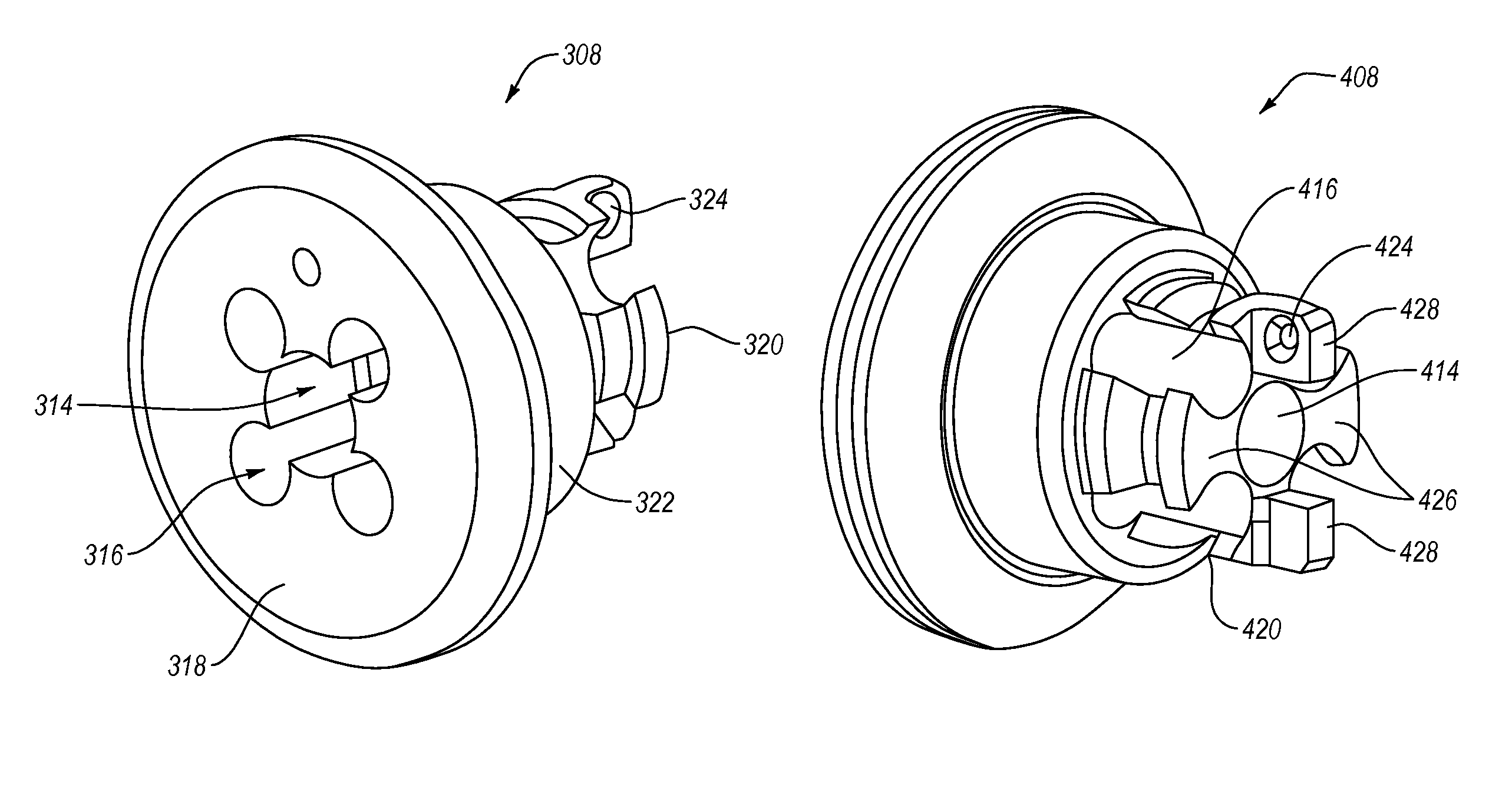
FIG. 5 is a perspective view of an embodiment of a ring 308 according to the present disclosure. The ring 308 may have a major channel 314 that extends through at least a longitudinal portion of the ring 308. In at least one embodiment, the major channel 314 may extend through the entire longitudinal length of the ring 308. The major channel 314 may have a substantially circular transverse cross-section (e.g., be cylindrical). In other embodiments, the major channel 314 may have a transverse cross-section having another shape, such as square, octagonal, other polygonal, elliptical, irregular, or combinations thereof. In some embodiments, the major channel 314 may have a constant transverse cross-section along the length of the major channel 314.
The major channel 314 may have one or more minor channels 316 spaced about the major channel 314. In some embodiments, the one or more minor channels 316 may overlap at least a portion of the major channel 314, as shown in FIG. 5. In other embodiments, the one or more minor channels 316 may extend through a portion of the longitudinal length of the ring 308 without overlapping any portion of the major channel 314. In some embodiments, the one or more minor channels 316 may have a substantially circular transverse cross-section (e.g., be cylindrical). In other embodiments, the one or more minor channels 316 may have a transverse cross-section having another shape, such as square, octagonal, other polygonal, elliptical, irregular, or combinations thereof. In some embodiments, the one or more minor channels 316 may have a constant transverse cross-section along the length of the one or more minor channels 316.
The ring 308 may have a distal face 318 and a proximal base 320 at opposing longitudinal ends of a body 322. It should be understood that the terms "distal" and "proximal" are used herein as relative to a medical professional operating a heart valve repair system similar to that described herein. In other applications, the face 318 and the base 320 may be oriented in a different relative direction to an operator. The face 318 may be substantially flat, or may have a curved surface. The face 318 may be convex relative to the body 322, concave relative to the body 322, have another curve, or combinations thereof. The face 318 may be configured to complimentarily mate with a desired medical device or other interface component. The base 320 may extend away from the body 322 in a direction opposite that of the face 322. The base 320 may have one or more connection points 324 thereon to allow fixation of the ring 308 to a delivery catheter or other elongated member that provides communication between the ring 308 and a control system or operator outside the patient's body. In some embodiments, the ring 308 may have a single connection point 324. In other embodiments, the ring 308 may have a plurality of connection points 324. The plurality of connection points 324 may be distributed symmetrically about the base 320 such that any application of force to the connection points 324 may be applied to the ring 308 symmetrically.
FIG. 6 illustrates a rear perspective view of an embodiment of a ring 408, according to the present disclosure. In some embodiments, the minor channels 416 of the ring 408 may substantially divide the base 420 into a plurality of posts 426. The plurality of posts 426 may be connected to the body 422. In some embodiments, the plurality of posts 426 may connect laterally to one another. In other embodiments, the plurality of posts 426 may not be connected to one another (e.g., the major channel 414 and plurality of minor channels 416 connect laterally to one another). In some embodiments, at least one of the posts 426 may have an extension 428 extending proximally therefrom. In embodiments having a plurality of extensions 428, the extensions may substantially radially oppose one another. As shown in FIG. 6, the plurality of extensions 428 may be space around and on opposite sides of the major channel 414. In at least one embodiment, one of the extensions 428 may have a connection point 424 thereon.
FIG. 7 illustrates a side view of another embodiment of a ring 508 according to the present disclosure. The ring 508 may have a face 518 with a face edge 530 that defines a face radius 532. The face radius 532 may be measured from a longitudinal axis 534 of the ring 508 to a radial outermost point of the face 518 and face edge 530. The face edge 530 may, in some embodiments, be a curved edge. In other embodiments, the face edge 530 may be a beveled edge. In yet other embodiments, the face 518 may not have a face edge 530, and the face 518 may extend substantially flat to the radial outermost point of the ring 508. The face radius 532 may be greater than a body radius 536. The body radius 536 may be measured from the longitudinal axis 534 to the radial outermost point of the body 522. In some embodiments, the body radius 536 may be configured to substantially match an inner radius of a delivery catheter (e.g., the delivery catheter 104 described in relation to FIG. 1 and FIG. 2). In other embodiments, the body radius 522 may be larger than the inner radius of the delivery catheter. In some embodiments, the body 522 may include one or more engagement features to engage with an inner surface of the delivery catheter.
The face radius 532 and the body radius 536 may have a face-to-body ratio in a range having upper and lower values including any of 1.20, 1.25, 1.30, 1.35, 1.40, 1.45, 1.50, 1.55, 1.60, 1.65, 1.70, 1.75, or any value therebetween. For example, the face radius 532 and the body radius 536 may have a face-to-body ratio in a range of 1.20 to 1.75. In another example, the face radius 532 and the body radius 536 may have a face-to-body ratio in a range of 1.30 to 1.70. In yet another example, the face radius 532 and the body radius 536 may have a face-to-body ratio in a range 1.40 to 1.60. In at least one example, the face radius 532 and the body radius 536 may have a face-to-body ratio of 1.50.
The base 520 of the ring 508 may define a base radius 538 measured from the longitudinal axis 534 to a radial outermost point of the plurality of posts 526. In some embodiments, the base radius 538 may be the same or less than an inner diameter of a compression coil or other inner support member (e.g., hypotube) of the delivery catheter. The base radius 538 may also be larger than the inner diameter of a compression coil or other inner support member of the delivery catheter to provide a compression fit between the base 520 and the compression coil or other inner support member. The face radius 532 and the base radius 538 may have a face-to-base ratio in a range having upper and lower values including any of 1.60, 1.65, 1.70, 1.75, 1.80, 1.85, 1.90, 1.95, 2.00, 2.05, 2.10, 2.15, 2.20, 2.25, 2.30, or any value therebetween. For example, the face radius 532 and the base radius 538 may have a face-to-base ratio in a range of 1.60 to 2.30. In another example, the face radius 532 and the base radius 538 may have a face-to-base ratio in a range of 1.65 to 2.00. In yet another example, the face radius 532 and the base radius 538 may have a face-to-base ratio in a range 1.70 to 1.80. In at least one example, the face radius 532 and the base radius 538 may have a face-to-base ratio of 1.75.
The base 520 and the plurality of posts 526 therein may include a radial notch 540. In some embodiments, the notch 540 may include an inclined distal surface and a substantially transverse proximal surface as depicted in FIG. 7. In other embodiments, the notch 540 may include an inclined distal surface and an inclined proximal surface. In yet other embodiments, the notch 540 may include a substantially transverse distal surface and a substantially transverse proximal surface. The notch 540 may have a radial depth that is in a range having upper and lower values of 10% of the base radius 538, 15%, 20%, 25%, 30%, 35%, 40% of the base radius 538, or any value therebetween. For example, the notch 540 may have a radial depth in a range of 10% to 40% of the base radius 538. In another example, the notch 540 may have a radial depth in a range of 20% to 30% of the base radius 538. In at least one example, the notch 540 may have a radial depth of 25% of the base radius 538.
The ring 508 may have an angle 542 between the body 522 and a portion of a head 544 at or near the distal end of the ring 508. The angle 542 may define a guide surface 546 located longitudinally and/or laterally between the head 544 and the body 522. The angle 542 may be measured between the outer surface of the body 522 and the guide surface 546. The angle 542 may be an obtuse angle where the guide surface 546 slopes radially and distally (i.e., toward the face 518 of the head 544). The guide surface 546 may have an angle such that longitudinal movement of the ring 508 relative to SGC and/or SGC tip (such as SGC 106 and SGC tip 110 described in relation to FIG. 1 and FIG. 2) may convert at least a portion of a longitudinal compression force between the ring 508 and SGC and/or SGC tip to a transverse force. For example, the guide surface 546 may contact and/or interact with a distal edge of the SGC and/or SGC tip at apply a compressive force thereto. The compressive force may be applied between the guide surface 546 and the distal edge of the SGC and/or SGC tip at an angle to the longitudinal axis 534 of the ring 508, urging the ring 508 toward a radially centered position within the SGC and/or SGC tip.
In some embodiments of the ring 508, the guide surface 546 may be substantially flat in longitudinal cross-section. In other embodiments, the guide surface 546 may be at least partially curved in longitudinal cross-section. The guide surface 546 may be concave and/or convex relative to the head 544. In yet other embodiments, the guide surface 546 may be a combination of curved portions and flat portions in longitudinal cross-section. The angle 542 of the guide surface 546 relative to the longitudinal axis 534 of the ring 508 may be within a range having upper and lower values including any of 100.degree., 110.degree., 120.degree., 130.degree., 140.degree., 150.degree., 160.degree., or any value therebetween. For example, the angle 542 of the guide surface 546 may be in a range of 100.degree. to 160.degree.. In another example, the angle 542 of the guide surface 546 may be in a range of 110.degree. to 140.degree.. In yet another example, the angle 542 of the guide surface 546 may be 120.degree..
FIG. 8 shows a longitudinal cross-section of the ring 508 of FIG. 7. The longitudinal cross-section shows the major channel 514 of the ring 508. As described herein, the major channel 514 may have a number of shapes in transverse cross-section, and while the size of the major channel 514 may be described in relation to a radius from the longitudinal axis 534 or diameter, the measurement of a radius should not be understood to limit the structure of part or the entire length of the major channel 514. In some embodiments, the major channel 514 may have a constant profile and/or radius in transverse cross-section along a longitudinal length thereof. In other embodiments, the major channel 514 may have a plurality of shapes and/or radii in transverse cross-section along a longitudinal length thereof. For example, the major channel 514 may have a distal radius 548, an intermediate radius 550, and a proximal radius 552. In some embodiments, the distal radius 548 may be greater than the intermediate radius 550. In other embodiments, the intermediate radius 550 may be less than the proximal radius 552. In yet other embodiments, the proximal radius 552 may be less than the distal radius 548 and the intermediate radius 550 may be less than the distal radius 548 and the proximal radius 552.
The major channel 514 may be configured to receive and substantially retain at least part of a connection arm therein. The connection arm and connection to the major channel 514 of the ring 508 will be described in more detail in relation to FIG. 11. Referring again to FIG. 8, the distal radius 548 of the major channel 514 may be configured to receive at least part of a connection arm. In some embodiments, the distal radius 548 may be configured to provide an interference fit with at least part of a connection arm. Similarly, the major channel 514 may have a distal portion 554 with a longitudinal length to receive at least part of a connection arm and retain the connection arm with substantial movement of the connection arm relative to the ring 508.
FIG. 9 is a distal view of an embodiment of a ring 608 according to the present disclosure. The ring 608 may have a major channel 614 and a plurality of minor channels 616. The face 618 of the ring 608 may include a visual indicator 656. In the depicted embodiment, the visual indicator 656 is a cross. In other embodiments, the visual indicator 656 may be a circle, a dot, a square, or any other identifiable shape that may render the face 618 of the ring 608 asymmetrical. As described herein, the major channel 614 and plurality of minor channels 616 may be distributed symmetrically about the longitudinal axis 634 of the ring 608. The ring 608 may otherwise exhibit one or more rotational symmetries (e.g., 180.degree., 120.degree., 90.degree., etc.). The visual indicator 656 may allow an operator to identify a particular orientation irrespective of other rotational symmetries of the ring 608. In some embodiments, the visual indicator 656 may be a recessed portion of the face 618. For example, the visual indicator 656 may be milled, stamped, or otherwise imprinted into the face 618 of the ring 608. In other embodiments, the visual indicator 656 may be a raised portion of the face 618. For example, the visual indicator 656 may be created on the face 618 by application of material thereto.
The distal view of FIG. 9 illustrates differences in a distal radius 648 and an intermediate radius 650 of the major channel 614. The transition between the distal radius 648 and the intermediate radius 650 in the major channel 614 may create a ledge 658 against which a connection arm may contact. The ledge 658 may be substantially annular. In some embodiments, the minor channels 616 may overlap with at least a portion of the major channel 614, such as in a distal portion of the major channel 614, and may overlap with at least part of the ledge 658.
A minor channel 616 may have a minor channel radius 660. In some embodiments, a minor channel 616 may have a constant minor channel radius 660 along the full longitudinal length of the minor channel 616. In other embodiments, the minor channel radius 660 may change over the longitudinal length of the minor channel 616. In some embodiments, all of the minor channels 616 may have substantially the same minor channel radius 660. In other embodiments, at least one of the minor channels 616 may have a different minor channel radius 660. The minor channels 616 may be positioned a minor channel distance 662 away from the major channel 614 in a transverse direction. For example, each minor channel 616 may have a minor longitudinal axis 664 that extends in the longitudinal direction and substantially parallel to the longitudinal axis 634 of the ring 608 and/or major channel 634. In some embodiments, the minor longitudinal axis 664 of each minor channel 616 may be an equal distance from the longitudinal axis 634 of the ring 608 and/or major channel 634. In other embodiments, the minor longitudinal axis 664 of at least one minor channel 616 may be a different distance from the longitudinal axis 634 of the ring 608 and/or major channel 634 as the minor longitudinal axis 664 of another minor channel 616.
FIG. 10 illustrates a proximal view of the ring 608 of FIG. 9. As described herein, the plurality of minor channels 616 extending longitudinally through the base 620 may define a plurality of post 626. The posts 626 may be further divided from one another by the major channel 614 located centrally to the posts 626. At least one of the posts 626 may have an extension 628 extending proximally therefrom. As shown in FIG. 10, an extension 628 may have a substantially constant lateral thickness irrespective of radial distance from the longitudinal axis 634 (i.e., having substantially parallel lateral surfaces). In other embodiments, the extension 628 may have other shapes in transverse cross-section. For example, the extension 628 may have non-parallel lateral surfaces and may taper toward the longitudinal axis 634, similar to the lateral surfaces of the posts 626, as illustrated in FIG. 10. In another example, the extension 628 may have non-parallel lateral surfaces and the extension may taper away the longitudinal axis 634.
As described herein, the extension 628 may have one or more connection points thereon to connect a wire thereto to limit or substantially prevent movement of the ring 608 relative to a delivery catheter. The extension 628 may also be configured to allow connection to a delivery catheter by a weld connection or other bonding of the extension material to a portion of the delivery catheter. For example, an extension 628 or other proximal portion of the ring 608 may be adhered to a body of the delivery catheter or to a support member of the delivery catheter, such as a compression coil. In at least one embodiment, the extension 628 may be laser welded to the compression coil of a delivery catheter. In other embodiments, an adhesive material may be applied between at least part of the ring 608 and the delivery catheter.
FIG. 11 illustrates a side cross-sectional view of an embodiment of a ring 708 having a connection arm 766 extending distally therefrom. The connection arm 766 may have a distal end 768 configured to retain and/or grip a medical device (e.g., a mitral clip) and a proximal end 770 configured to connect to the ring 708. In some embodiments, the proximal end 770 may be configured to fit in the major channel 714 with an interference fit therein. The interference fit between the distal radius 748 of the major channel 714 and the OD 772 of the connection arm 766 may be sufficient to limit or substantially prevent movement of the connection arm 766 relative to the ring 708. In other embodiments, additional reinforcement of the connection therebetween may be provided by an adhesive material between the ring 708 and the connection arm 766. In yet other embodiments, the connection between the ring 708 and the connection arm 766 may include welding, brazing, or otherwise bonding the material of the connection arm 766 to the material of the ring 708.
A medical device may be retained on the connection arm 766 by a wire or other elongate member extending through the major channel 714 and the connection arm 766 to the medical device. The connection arm 766 may have an ID 774 defining a central bore 776 extending therethrough. The central bore 776 may be coaxial with the longitudinal axis 734 of the ring 708 and/or major channel 714. The ID 774 of the connection arm 766 may be substantially the same as the intermediate radius 750. In some embodiments, the central bore 776 and major channel 714 may provide a channel having a substantially continuous inner surface.
The articles "a," "an," and "the" are intended to mean that there are one or more of the elements in the preceding descriptions. The terms "comprising," "including," and "having" are intended to be inclusive and mean that there may be additional elements other than the listed elements. Additionally, it should be understood that references to "one embodiment" or "an embodiment" of the present disclosure are not intended to be interpreted as excluding the existence of additional embodiments that also incorporate the recited features. Numbers, percentages, ratios, or other values stated herein are intended to include that value, and also other values that are "about" or "approximately" the stated value, as would be appreciated by one of ordinary skill in the art encompassed by embodiments of the present disclosure. A stated value should therefore be interpreted broadly enough to encompass values that are at least close enough to the stated value to perform a desired function or achieve a desired result. The stated values include at least the variation to be expected in a suitable manufacturing or production process, and may include values that are within 5%, within 1%, within 0.1%, or within 0.01% of a stated value.
A person having ordinary skill in the art should realize in view of the present disclosure that equivalent constructions do not depart from the spirit and scope of the present disclosure, and that various changes, substitutions, and alterations may be made to embodiments disclosed herein without departing from the spirit and scope of the present disclosure. Equivalent constructions, including functional "means-plus-function" clauses are intended to cover the structures described herein as performing the recited function, including both structural equivalents that operate in the same manner, and equivalent structures that provide the same function. It is the express intention of the applicant not to invoke means-plus-function or other functional claiming for any claim except for those in which the words `means for` appear together with an associated function. Each addition, deletion, and modification to the embodiments that falls within the meaning and scope of the claims is to be embraced by the claims.
The terms "approximately," "about," and "substantially" as used herein represent an amount close to the stated amount that still performs a desired function or achieves a desired result. For example, the terms "approximately," "about," and "substantially" may refer to an amount that is within less than 5% of, within less than 1% of, within less than 0.1% of, and within less than 0.01% of a stated amount. Further, it should be understood that any directions or reference frames in the preceding description are merely relative directions or movements. For example, any references to "up" and "down" or "above" or "below" are merely descriptive of the relative position or movement of the related elements.
The present disclosure may be embodied in other specific forms without departing from its spirit or characteristics. The described embodiments are to be considered as illustrative and not restrictive. The scope of the disclosure is, therefore, indicated by the appended claims rather than by the foregoing description. Changes that come within the meaning and range of equivalency of the claims are to be embraced within their scope.
* * * * *
D00000
D00001
D00002
D00003
D00004
D00005
D00006
D00007
XML
uspto.report is an independent third-party trademark research tool that is not affiliated, endorsed, or sponsored by the United States Patent and Trademark Office (USPTO) or any other governmental organization. The information provided by uspto.report is based on publicly available data at the time of writing and is intended for informational purposes only.
While we strive to provide accurate and up-to-date information, we do not guarantee the accuracy, completeness, reliability, or suitability of the information displayed on this site. The use of this site is at your own risk. Any reliance you place on such information is therefore strictly at your own risk.
All official trademark data, including owner information, should be verified by visiting the official USPTO website at www.uspto.gov. This site is not intended to replace professional legal advice and should not be used as a substitute for consulting with a legal professional who is knowledgeable about trademark law.