Composite vertebral spacers and instrument
Voellmicke Feb
U.S. patent number 10,206,787 [Application Number 15/001,339] was granted by the patent office on 2019-02-19 for composite vertebral spacers and instrument. This patent grant is currently assigned to Medos International Sarl. The grantee listed for this patent is Medos International Sarl. Invention is credited to John C. Voellmicke.


View All Diagrams
| United States Patent | 10,206,787 |
| Voellmicke | February 19, 2019 |
Composite vertebral spacers and instrument
Abstract
An intervertebral fusion cage that is adapted to contain an inserter within its inner volume during insertion of the cage.
| Inventors: | Voellmicke; John C. (Franklin, MA) | ||||||||||
|---|---|---|---|---|---|---|---|---|---|---|---|
| Applicant: |
|
||||||||||
| Assignee: | Medos International Sarl (Le
Locle, CH) |
||||||||||
| Family ID: | 39544044 | ||||||||||
| Appl. No.: | 15/001,339 | ||||||||||
| Filed: | January 20, 2016 |
Prior Publication Data
| Document Identifier | Publication Date | |
|---|---|---|
| US 20160128846 A1 | May 12, 2016 | |
Related U.S. Patent Documents
| Application Number | Filing Date | Patent Number | Issue Date | ||
|---|---|---|---|---|---|
| 14698179 | Apr 28, 2015 | 9265621 | |||
| 11615077 | May 26, 2015 | 9039768 | |||
| Current U.S. Class: | 1/1 |
| Current CPC Class: | A61F 2/447 (20130101); A61F 2/4611 (20130101); A61F 2/442 (20130101); A61F 2/4455 (20130101); A61F 2002/4627 (20130101); A61F 2002/30433 (20130101); A61F 2002/30841 (20130101); A61F 2/28 (20130101); A61F 2210/0004 (20130101); A61F 2220/0041 (20130101); A61F 2002/30672 (20130101); A61F 2002/30772 (20130101); A61F 2002/3082 (20130101); A61F 2220/0091 (20130101); A61F 2310/00011 (20130101); A61F 2250/0059 (20130101); A61F 2310/00179 (20130101); A61F 2002/30062 (20130101); A61F 2002/30471 (20130101); A61F 2002/2835 (20130101); A61F 2002/30166 (20130101); A61F 2230/0013 (20130101); A61F 2002/4629 (20130101); A61F 2002/2817 (20130101); A61F 2002/30904 (20130101); A61F 2002/30112 (20130101); A61F 2002/30579 (20130101); A61F 2230/0004 (20130101); A61F 2230/0028 (20130101); A61F 2310/00359 (20130101); A61F 2002/30131 (20130101) |
| Current International Class: | A61F 2/44 (20060101); A61F 2/46 (20060101); A61F 2/30 (20060101); A61F 2/28 (20060101) |
References Cited [Referenced By]
U.S. Patent Documents
| 1636636 | July 1927 | Humble |
| 1677337 | July 1928 | Grove |
| 2304703 | December 1942 | O'Leary |
| 4105034 | August 1978 | Shalaby |
| 4130639 | December 1978 | Shalaby |
| 4140678 | February 1979 | Shalaby |
| 4141087 | February 1979 | Shalaby |
| 4205399 | June 1980 | Shalaby |
| 4208511 | June 1980 | Shalaby |
| 4743256 | May 1988 | Brantigan |
| 4904261 | February 1990 | Dove |
| 4955908 | September 1990 | Frey |
| 5041113 | August 1991 | Biedermann |
| 5123926 | June 1992 | Pisharodi |
| 5147361 | September 1992 | Ojima et al. |
| 5209751 | May 1993 | Farris et al. |
| 5306308 | April 1994 | Gross et al. |
| 5352231 | October 1994 | Brumfield |
| 5391170 | February 1995 | McGuire |
| 5395372 | March 1995 | Holt |
| 5397364 | March 1995 | Kozak |
| 5443514 | August 1995 | Steffee |
| 5443515 | August 1995 | Cohen |
| 5464407 | November 1995 | McGuire |
| 5464929 | November 1995 | Bezwada |
| 5499986 | March 1996 | Dimarco |
| 5529580 | June 1996 | Kusunoki |
| 5534031 | July 1996 | Matsuzaki |
| 5578034 | November 1996 | Estes |
| 5591166 | January 1997 | Bernhardt et al. |
| 5595751 | January 1997 | Bezwada |
| 5597579 | January 1997 | Bezwada |
| 5601553 | February 1997 | Trebing et al. |
| 5607687 | March 1997 | Bezwada |
| 5609636 | March 1997 | Kohrs et al. |
| 5618552 | April 1997 | Bezwada |
| 5620458 | April 1997 | Green et al. |
| 5620698 | April 1997 | Bezwada |
| 5645598 | July 1997 | Brosnahan, III |
| 5645850 | July 1997 | Bezwada |
| 5648088 | July 1997 | Bezwada |
| 5662655 | September 1997 | Laboureau |
| 5676666 | October 1997 | Oxland et al. |
| 5698213 | December 1997 | Jamiolkowski |
| 5700583 | December 1997 | Jamiolkowski |
| 5713899 | February 1998 | Marnay |
| 5716415 | February 1998 | Steffee |
| 5755796 | May 1998 | Ibo et al. |
| 5776196 | July 1998 | Matsuzaki |
| 5779707 | July 1998 | Bertholet |
| 5785713 | July 1998 | Jobe |
| 5788698 | August 1998 | Savornin |
| 5797912 | August 1998 | Runciman |
| 5797918 | August 1998 | McGuire |
| 5800435 | September 1998 | Errico et al. |
| 5800440 | September 1998 | Stead |
| 5859150 | January 1999 | Jamiolkowski |
| 5888223 | March 1999 | Bray, Jr. |
| 5904689 | May 1999 | Jonjic |
| 5913860 | June 1999 | Scholl |
| 6039761 | March 2000 | Li |
| 6049026 | April 2000 | Muschler |
| 6056749 | May 2000 | Kuslich |
| 6066175 | May 2000 | Henderson |
| 6086593 | July 2000 | Bonutti |
| 6093205 | July 2000 | McLeod |
| 6099531 | August 2000 | Bonutti |
| 6106557 | August 2000 | Robioneck |
| 6117174 | September 2000 | Nolan |
| 6120503 | September 2000 | Michelson |
| 6126689 | October 2000 | Brett |
| 6139550 | October 2000 | Michelson |
| 6156037 | December 2000 | LeHuec |
| 6159211 | December 2000 | Boriani |
| 6159244 | December 2000 | Suddaby |
| 6174311 | January 2001 | Branch et al. |
| 6179875 | January 2001 | Von Strempel |
| 6190414 | February 2001 | Young et al. |
| 6193757 | February 2001 | Foley et al. |
| 6200306 | March 2001 | Klostermeyer |
| 6206922 | March 2001 | Zdeblick |
| 6224602 | May 2001 | Hayes |
| 6231610 | May 2001 | Geisler |
| 6235059 | May 2001 | Benezech |
| 6306170 | October 2001 | Ray |
| 6330845 | December 2001 | Meulink |
| 6336928 | January 2002 | Guerin |
| 6342055 | January 2002 | Eisermann |
| 6342074 | January 2002 | Simpson |
| 6364880 | April 2002 | Michelson |
| 6368351 | April 2002 | Glenn et al. |
| 6375462 | April 2002 | Holweg et al. |
| 6387130 | May 2002 | Stone |
| 6395031 | May 2002 | Foley et al. |
| 6406478 | June 2002 | Kuo |
| 6409766 | June 2002 | Brett |
| 6413278 | July 2002 | Marchosky |
| 6423063 | July 2002 | Bonutti |
| 6428575 | August 2002 | Koo |
| 6432106 | August 2002 | Fraser |
| 6447544 | September 2002 | Michelson |
| 6447546 | September 2002 | Bramlet |
| 6454769 | September 2002 | Wagner et al. |
| 6461359 | October 2002 | Tribus |
| 6471724 | October 2002 | Zdeblick |
| 6488710 | December 2002 | Besselink |
| 6508818 | January 2003 | Steiner et al. |
| 6558387 | May 2003 | Errico |
| 6558423 | May 2003 | Michelson |
| 6562073 | May 2003 | Foley |
| 6565570 | May 2003 | Sterett |
| 6572619 | June 2003 | Santilli |
| 6579290 | June 2003 | Hardcastle |
| 6602257 | August 2003 | Thramann |
| 6629998 | October 2003 | Lin |
| 6682563 | January 2004 | Scharf |
| 6695846 | February 2004 | Richelsoph |
| 6730125 | May 2004 | Lin |
| 6730127 | May 2004 | Michelson |
| 6733531 | May 2004 | Trieu |
| 6736850 | May 2004 | Davis |
| 6743257 | June 2004 | Castro |
| 6745255 | June 2004 | Yen et al. |
| 6761738 | July 2004 | Boyd |
| 6770096 | August 2004 | Bolger |
| 6773437 | August 2004 | Ogilvie |
| 6776781 | August 2004 | Uwaydah |
| 6805714 | October 2004 | Sutcliffe |
| 6808537 | October 2004 | Michelson |
| 6824564 | November 2004 | Crozet |
| 6824565 | November 2004 | Muhanna et al. |
| 6833006 | December 2004 | Foley et al. |
| 6835208 | December 2004 | Marchosky |
| 6837905 | January 2005 | Lieberman |
| 6849093 | February 2005 | Michelson |
| 6890335 | May 2005 | Grabowski |
| 6890355 | May 2005 | Michelson |
| 6945973 | September 2005 | Bray |
| 6972019 | December 2005 | Michelson |
| 6974479 | December 2005 | Trieu |
| 6974480 | December 2005 | Messerli et al. |
| 6984234 | January 2006 | Bray |
| 7001385 | February 2006 | Bonutti |
| 7033394 | April 2006 | Michelson |
| 7041135 | May 2006 | Michelson |
| 7044971 | May 2006 | Suddaby |
| 7056341 | June 2006 | Crozet |
| 7063491 | June 2006 | French |
| 7070598 | July 2006 | Lim et al. |
| 7077864 | July 2006 | Byrd, III |
| 7087055 | August 2006 | Lim et al. |
| 7112222 | September 2006 | Fraser |
| 7112223 | September 2006 | Davis |
| 7135024 | November 2006 | Cook |
| 7135043 | November 2006 | Nakahara |
| 7163561 | January 2007 | Michelson |
| 7172627 | February 2007 | Fiere |
| 7226482 | June 2007 | Messerli |
| 7232463 | June 2007 | Falahee |
| 7232464 | June 2007 | Mathieu |
| 7238203 | July 2007 | Bagga |
| 7238206 | July 2007 | Lange |
| 7255698 | August 2007 | Michelson |
| 7276081 | October 2007 | Coates |
| 7288094 | October 2007 | Lindemann |
| 7288095 | October 2007 | Baynham |
| 7288114 | October 2007 | Lange |
| 7306605 | December 2007 | Ross |
| 7309358 | December 2007 | Berry |
| 7311734 | December 2007 | Van Hoeck |
| 7316714 | January 2008 | Gordon |
| 7318839 | January 2008 | Malberg et al. |
| 7323011 | January 2008 | Shepard |
| 7326248 | February 2008 | Michelson |
| 7338525 | March 2008 | Ferree |
| 7341587 | March 2008 | Molz |
| 7341590 | March 2008 | Ferree |
| 7354452 | April 2008 | Foley |
| 7361193 | April 2008 | Frey |
| 7332209 | October 2008 | Michelson |
| 7435262 | October 2008 | Michelson |
| 7438715 | October 2008 | Doubler |
| 7452370 | November 2008 | Anderson |
| 7491237 | February 2009 | Randall |
| 7527641 | May 2009 | Suh |
| 7594931 | September 2009 | Louis et al. |
| 7594932 | September 2009 | Aferzon |
| 7601171 | October 2009 | Ainsworth et al. |
| 7601173 | October 2009 | Messerli |
| 7608062 | October 2009 | Sweeney |
| 7618456 | November 2009 | Mathieu |
| 7628816 | December 2009 | Magerl |
| 7641665 | January 2010 | Zubok |
| 7655042 | February 2010 | Foley et al. |
| 7658766 | February 2010 | Melkent |
| 7662182 | February 2010 | Zubok |
| 7674279 | March 2010 | Johnson |
| 7704255 | April 2010 | Michelson |
| 7726002 | June 2010 | Shimp et al. |
| 7794502 | September 2010 | Michelson |
| 7815643 | October 2010 | Johnson et al. |
| 7815681 | October 2010 | Ferguson |
| 7846206 | December 2010 | Leonard et al. |
| 7846210 | December 2010 | Perez-Cruet et al. |
| 7862616 | January 2011 | Lechmann et al. |
| 7871441 | January 2011 | Eckman |
| 7875062 | January 2011 | Lindemann |
| 7875076 | January 2011 | Mathieu |
| 7883531 | February 2011 | de Coninck et al. |
| 7887591 | February 2011 | Aebi et al. |
| 7887595 | February 2011 | Pimenta |
| 7909877 | March 2011 | Krueger et al. |
| 7993403 | August 2011 | Foley et al. |
| 8002808 | August 2011 | Morrison et al. |
| 8007523 | August 2011 | Wagner |
| 8187329 | May 2012 | Theofilos |
| 8206423 | June 2012 | Siegal |
| 8216312 | July 2012 | Gray |
| 8323342 | December 2012 | Schwab |
| 8336559 | December 2012 | Kallabat et al. |
| 8337559 | December 2012 | Hansell et al. |
| 8343219 | January 2013 | Allain |
| 8349015 | January 2013 | Bae et al. |
| 8357200 | January 2013 | Adl |
| 8454694 | June 2013 | Armstrong et al. |
| 8460385 | June 2013 | Wensel |
| 8460387 | June 2013 | Theofilos |
| 8470044 | June 2013 | Bertholet et al. |
| 8480747 | July 2013 | Melkent et al. |
| 8486109 | July 2013 | Siegal |
| 8491658 | July 2013 | Etminan |
| 8496691 | July 2013 | Blain |
| 8496708 | July 2013 | Blain |
| 8500783 | August 2013 | Baynham |
| 8551175 | October 2013 | Wensel |
| 8562651 | October 2013 | Metcalf et al. |
| 8597330 | December 2013 | Siegal |
| 8613772 | December 2013 | Bray et al. |
| 8617245 | December 2013 | Brett |
| 8628578 | January 2014 | Miller et al. |
| 8641765 | February 2014 | Muhanna |
| 8690928 | April 2014 | Walkenhorst et al. |
| 8690948 | April 2014 | Armstrong et al. |
| 8747443 | June 2014 | Aferzon |
| 8758439 | June 2014 | Linares |
| 8821555 | September 2014 | Bae |
| 8900235 | December 2014 | Siegal |
| 8906098 | December 2014 | Siegal |
| 8932359 | January 2015 | Brett |
| 8956416 | February 2015 | McCarthy |
| 9005293 | April 2015 | Moskowitz et al. |
| 9005295 | April 2015 | Kueenzi et al. |
| 9138330 | September 2015 | Hansell et al. |
| 9192419 | November 2015 | McDonough et al. |
| 9248028 | February 2016 | Gamache |
| 9265546 | February 2016 | Blain |
| 9265621 | February 2016 | Voellmicke |
| 9278009 | March 2016 | Bray et al. |
| 9289311 | March 2016 | Whipple |
| 9402738 | August 2016 | Niemic |
| 2001/0031968 | October 2001 | Dorchak et al. |
| 2002/0029044 | March 2002 | Monassevitch |
| 2002/0029082 | March 2002 | Muhanna |
| 2002/0095155 | July 2002 | Michelson |
| 2002/0099376 | July 2002 | Michelson |
| 2002/0138146 | September 2002 | Jackson |
| 2002/0143328 | October 2002 | Shulzas |
| 2002/0151976 | October 2002 | Foley et al. |
| 2002/0156475 | October 2002 | Lerch et al. |
| 2003/0004576 | January 2003 | Thalgott |
| 2003/0028197 | February 2003 | Hanson |
| 2003/0045940 | March 2003 | Eberlein et al. |
| 2003/0050645 | March 2003 | Parker |
| 2003/0083748 | May 2003 | Lee et al. |
| 2003/0100949 | May 2003 | Michelson |
| 2003/0125739 | July 2003 | Bagga |
| 2003/0130739 | July 2003 | Gerbec et al. |
| 2003/0153975 | August 2003 | Byrd |
| 2003/0158555 | August 2003 | Sanders |
| 2003/0187440 | October 2003 | Richelsoph et al. |
| 2003/0187506 | October 2003 | Ross |
| 2003/0195632 | October 2003 | Foley |
| 2003/0225409 | December 2003 | Freid et al. |
| 2004/0024464 | February 2004 | Errico |
| 2004/0034430 | February 2004 | Falahee |
| 2004/0092929 | May 2004 | Zindrick |
| 2004/0106996 | June 2004 | Liu et al. |
| 2004/0111089 | June 2004 | Stevens et al. |
| 2004/0127902 | July 2004 | Suzuki |
| 2004/0127990 | July 2004 | Bartish |
| 2004/0138662 | July 2004 | Landry et al. |
| 2004/0153065 | August 2004 | Lim |
| 2004/0153072 | August 2004 | Bonutti |
| 2004/0167625 | August 2004 | Beyar et al. |
| 2004/0193269 | September 2004 | Fraser |
| 2004/0199253 | October 2004 | Link |
| 2004/0199254 | October 2004 | Louis |
| 2004/0210219 | October 2004 | Bray |
| 2004/0249377 | December 2004 | Kaes |
| 2004/0254644 | December 2004 | Taylor |
| 2004/0260286 | December 2004 | Ferree |
| 2005/0021144 | January 2005 | Malberg et al. |
| 2005/0033433 | February 2005 | Michelson |
| 2005/0038513 | February 2005 | Michelson |
| 2005/0043800 | February 2005 | Paul et al. |
| 2005/0065608 | March 2005 | Michelson |
| 2005/0071006 | March 2005 | Kirschman |
| 2005/0071008 | March 2005 | Kirschman |
| 2005/0085913 | April 2005 | Fraser |
| 2005/0096657 | May 2005 | Autericque et al. |
| 2005/0101960 | May 2005 | Fiere et al. |
| 2005/0113920 | May 2005 | Foley et al. |
| 2005/0143749 | June 2005 | Zalenski |
| 2005/0143827 | June 2005 | Globerman et al. |
| 2005/0149192 | July 2005 | Zucherman |
| 2005/0149193 | July 2005 | Zucherman |
| 2005/0154391 | July 2005 | Doherty et al. |
| 2005/0159813 | July 2005 | Molz |
| 2005/0177240 | August 2005 | Blain |
| 2005/0177245 | August 2005 | Leatherbury et al. |
| 2005/0182416 | August 2005 | Lim et al. |
| 2005/0209696 | September 2005 | Lin et al. |
| 2005/0251260 | November 2005 | Gerber et al. |
| 2005/0261768 | November 2005 | Trieu |
| 2005/0277938 | December 2005 | Parsons |
| 2005/0278036 | December 2005 | Leonard |
| 2006/0025860 | February 2006 | Li |
| 2006/0030851 | February 2006 | Bray |
| 2006/0058801 | March 2006 | Schlienger et al. |
| 2006/0079961 | April 2006 | Michelson |
| 2006/0085071 | April 2006 | Lechmann |
| 2006/0129424 | June 2006 | Chan |
| 2006/0142765 | June 2006 | Dixon |
| 2006/0142858 | June 2006 | Colleran et al. |
| 2006/0142863 | June 2006 | Fraser |
| 2006/0152863 | June 2006 | Fraser |
| 2006/0178745 | August 2006 | Bartish et al. |
| 2006/0211952 | September 2006 | Kennedy |
| 2006/0229609 | October 2006 | Wang |
| 2006/0229729 | October 2006 | Gordon et al. |
| 2006/0235403 | October 2006 | Blain |
| 2006/0235409 | October 2006 | Blain |
| 2006/0235411 | October 2006 | Blain et al. |
| 2006/0235518 | October 2006 | Blain |
| 2006/0235535 | October 2006 | Ferree |
| 2006/0241597 | October 2006 | Mitchell et al. |
| 2006/0241761 | October 2006 | Gately |
| 2006/0247650 | November 2006 | Yerby et al. |
| 2006/0259147 | November 2006 | Krishna et al. |
| 2006/0265068 | November 2006 | Schwab |
| 2006/0293753 | December 2006 | Thramann |
| 2007/0049941 | March 2007 | Thramann |
| 2007/0055252 | March 2007 | Blain |
| 2007/0067035 | March 2007 | Falahee |
| 2007/0073398 | March 2007 | Fabian et al. |
| 2007/0106384 | May 2007 | Bray |
| 2007/0106388 | May 2007 | Micheslon |
| 2007/0129804 | June 2007 | Bentley |
| 2007/0162138 | July 2007 | Heinz |
| 2007/0198016 | August 2007 | Zang et al. |
| 2007/0213737 | September 2007 | Schemmerhorn et al. |
| 2007/0213820 | September 2007 | Magerl |
| 2007/0219635 | September 2007 | Mathieu |
| 2007/0233118 | October 2007 | McLain |
| 2007/0233253 | October 2007 | Bray |
| 2007/0233261 | October 2007 | Lopez et al. |
| 2007/0233263 | October 2007 | Melkent |
| 2007/0250167 | October 2007 | Bray |
| 2007/0255416 | November 2007 | Melkent |
| 2007/0265631 | November 2007 | Fox |
| 2007/0270957 | November 2007 | Heinz |
| 2007/0270965 | November 2007 | Ferguson |
| 2007/0276490 | November 2007 | Mateyka |
| 2007/0282449 | December 2007 | De Villiers et al. |
| 2007/0293948 | December 2007 | Bagga |
| 2007/0299521 | December 2007 | Glenn et al. |
| 2008/0015694 | January 2008 | Tribus |
| 2008/0027550 | January 2008 | Link |
| 2008/0033440 | February 2008 | Moskowitz |
| 2008/0051890 | February 2008 | Waugh et al. |
| 2008/0051897 | February 2008 | Lopez et al. |
| 2008/0065219 | March 2008 | Dye |
| 2008/0077247 | March 2008 | Murillo |
| 2008/0082173 | April 2008 | Delurio |
| 2008/0097436 | April 2008 | Culbert |
| 2008/0103597 | May 2008 | Lechman et al. |
| 2008/0103598 | May 2008 | Trudeau et al. |
| 2008/0109005 | May 2008 | Trudeau et al. |
| 2008/0125865 | May 2008 | Abdelgany |
| 2008/0132949 | June 2008 | Aferzon |
| 2008/0132958 | June 2008 | Pech |
| 2008/0133012 | June 2008 | McGuckin |
| 2008/0133014 | June 2008 | Gately et al. |
| 2008/0161925 | July 2008 | Brittan |
| 2008/0167666 | July 2008 | Fiere |
| 2008/0177307 | July 2008 | Moskowitz |
| 2008/0183293 | July 2008 | Parry |
| 2008/0183294 | July 2008 | Adl |
| 2008/0221690 | September 2008 | Chaput |
| 2008/0221694 | September 2008 | Warnick et al. |
| 2008/0243136 | October 2008 | Prager |
| 2008/0249569 | October 2008 | Waugh |
| 2008/0249575 | October 2008 | Waugh |
| 2008/0249625 | October 2008 | Waugh |
| 2008/0255620 | October 2008 | Strauss |
| 2008/0269806 | October 2008 | Zhang |
| 2008/0281425 | November 2008 | Thalgott |
| 2008/0294262 | November 2008 | Levieux |
| 2008/0300601 | December 2008 | Fabian et al. |
| 2008/0300634 | December 2008 | Gray |
| 2008/0306596 | December 2008 | Jones |
| 2008/0306598 | December 2008 | Hansen |
| 2008/0312698 | December 2008 | Bergeron |
| 2008/0312742 | December 2008 | Abernathie |
| 2009/0012529 | January 2009 | Blain et al. |
| 2009/0030421 | January 2009 | Hawkins |
| 2009/0030519 | January 2009 | Falahee |
| 2009/0030520 | January 2009 | Biedermann |
| 2009/0062921 | March 2009 | Michelson |
| 2009/0088849 | April 2009 | Armstrong |
| 2009/0099554 | April 2009 | Forster |
| 2009/0099610 | April 2009 | Johnson et al. |
| 2009/0105771 | April 2009 | Lei |
| 2009/0105774 | April 2009 | Jones |
| 2009/0105830 | April 2009 | Jones |
| 2009/0105831 | April 2009 | Jones |
| 2009/0125028 | May 2009 | Teisen et al. |
| 2009/0131988 | May 2009 | Bush |
| 2009/0132054 | May 2009 | Zeegers |
| 2009/0143859 | June 2009 | McClellan |
| 2009/0164020 | June 2009 | Janowski |
| 2009/0182428 | July 2009 | McClellan et al. |
| 2009/0182430 | July 2009 | Tyber |
| 2009/0192549 | July 2009 | Sanders |
| 2009/0192613 | July 2009 | Wing |
| 2009/0192614 | July 2009 | Beger et al. |
| 2009/0192615 | July 2009 | Tyber |
| 2009/0192616 | July 2009 | Zielinski |
| 2009/0198245 | August 2009 | Phan |
| 2009/0198287 | August 2009 | Chiu |
| 2009/0198339 | August 2009 | Kleiner et al. |
| 2009/0210062 | August 2009 | Thalgott |
| 2009/0210064 | August 2009 | Lechmann |
| 2009/0224023 | September 2009 | Moskowitz |
| 2009/0234364 | September 2009 | Crook |
| 2009/0265007 | October 2009 | Colleran |
| 2009/0287251 | November 2009 | Bae |
| 2009/0306779 | December 2009 | Ahn |
| 2009/0326543 | December 2009 | Fabian |
| 2009/0326580 | December 2009 | Anderson et al. |
| 2009/0326589 | December 2009 | Lemoine et al. |
| 2010/0004747 | January 2010 | Lin |
| 2010/0016901 | January 2010 | Robinson |
| 2010/0016973 | January 2010 | De Villiers et al. |
| 2010/0023128 | January 2010 | Malberg |
| 2010/0030334 | February 2010 | Molz, IV |
| 2010/0036496 | February 2010 | Yu |
| 2010/0042159 | February 2010 | Butler |
| 2010/0057206 | March 2010 | Duffield |
| 2010/0069969 | March 2010 | Ampuero |
| 2010/0070037 | March 2010 | Parry et al. |
| 2010/0087925 | April 2010 | Kostuik |
| 2010/0106249 | April 2010 | Tyber |
| 2010/0145457 | June 2010 | Felt |
| 2010/0145459 | June 2010 | McDonough |
| 2010/0145460 | June 2010 | McDonough |
| 2010/0185289 | July 2010 | Kirwan |
| 2010/0185292 | July 2010 | Hochschuler et al. |
| 2010/0204739 | August 2010 | Bae et al. |
| 2010/0217325 | August 2010 | Hochschuler et al. |
| 2010/0217393 | August 2010 | Theofilos |
| 2010/0249935 | September 2010 | Slivka |
| 2010/0249937 | September 2010 | Blain et al. |
| 2010/0286777 | November 2010 | Errico |
| 2010/0286781 | November 2010 | Bullard |
| 2010/0286783 | November 2010 | Lechmann et al. |
| 2010/0292696 | November 2010 | Chantelot |
| 2010/0292737 | November 2010 | Suh |
| 2010/0305704 | December 2010 | Messerli |
| 2010/0312345 | December 2010 | Duffield |
| 2011/0009908 | January 2011 | Ferguson |
| 2011/0009966 | January 2011 | Michelson |
| 2011/0015675 | January 2011 | Howard |
| 2011/0015745 | January 2011 | Bucci |
| 2011/0082550 | April 2011 | Yeh |
| 2011/0082555 | April 2011 | Martz |
| 2011/0098747 | April 2011 | Donner et al. |
| 2011/0106159 | May 2011 | Nazeck |
| 2011/0144703 | June 2011 | Krause et al. |
| 2011/0184415 | July 2011 | Anderson et al. |
| 2011/0190892 | August 2011 | Kirschman |
| 2011/0202136 | August 2011 | Brittan et al. |
| 2011/0208311 | August 2011 | Janowski |
| 2011/0213421 | September 2011 | Binder et al. |
| 2011/0230971 | September 2011 | Donner et al. |
| 2011/0251689 | October 2011 | Seifert |
| 2011/0319998 | December 2011 | O'Neil |
| 2012/0041559 | February 2012 | Melkent et al. |
| 2012/0078371 | March 2012 | Gamache |
| 2012/0078372 | March 2012 | Gamache |
| 2012/0078373 | March 2012 | Gamache |
| 2012/0083889 | April 2012 | Purcell et al. |
| 2012/0150301 | June 2012 | Gamache |
| 2012/0150303 | June 2012 | Linares |
| 2012/0158143 | June 2012 | Shapiro |
| 2012/0197401 | August 2012 | Duncan |
| 2012/0203230 | August 2012 | Adams |
| 2012/0209331 | August 2012 | Michelson |
| 2012/0226319 | September 2012 | Armstrong et al. |
| 2012/0253406 | October 2012 | Bae |
| 2013/0060337 | March 2013 | Petersheim et al. |
| 2013/0073044 | March 2013 | Gamache |
| 2013/0166027 | June 2013 | Bellas |
| 2013/0238095 | September 2013 | Pavento et al. |
| 2013/0268080 | October 2013 | Melkent et al. |
| 2013/0310939 | November 2013 | Fabian |
| 2013/0325071 | December 2013 | Niemiec et al. |
| 2013/0345813 | December 2013 | Frank et al. |
| 2014/0039623 | February 2014 | Iott et al. |
| 2014/0067069 | March 2014 | Lopez |
| 2014/0107786 | April 2014 | Geisler et al. |
| 2014/0114415 | April 2014 | Tyber |
| 2014/0135930 | May 2014 | Georges |
| 2014/0142705 | May 2014 | Duffield et al. |
| 2014/0156009 | June 2014 | Armstrong et al. |
| 2014/0172103 | June 2014 | O'Neil et al. |
| 2014/0364917 | December 2014 | Sandstrom |
| 2015/0297356 | October 2015 | Gamache et al. |
| 2015/0313721 | November 2015 | Gamache et al. |
| 2015/0374511 | December 2015 | Pavento et al. |
| 2016/0128846 | May 2016 | Voellmicke |
| 2016/0213487 | July 2016 | Wilson et al. |
| 2016/0324662 | November 2016 | McDonough et al. |
| 201244104 | May 2009 | CN | |||
| 19710392 | Jul 1999 | DE | |||
| 1459711 | Jul 2007 | EP | |||
| 1683490 | Jul 2008 | EP | |||
| 1506753 | Sep 2009 | EP | |||
| 1774926 | Jun 2010 | EP | |||
| 1847240 | Nov 2011 | EP | |||
| 2894130 | Jun 2007 | FR | |||
| 2220729 | Jan 1990 | GB | |||
| 2457673 | Aug 2009 | GB | |||
| WO 1998/004217 | Feb 1998 | WO | |||
| WO 1998/034568 | Aug 1998 | WO | |||
| WO 1999/052473 | Oct 1999 | WO | |||
| WO 1999/038463 | Nov 1999 | WO | |||
| WO 2001/008864 | Feb 2001 | WO | |||
| WO 2002/013732 | May 2002 | WO | |||
| WO 2003/003951 | Jan 2003 | WO | |||
| WO 2003/005938 | Jan 2003 | WO | |||
| WO 2003/005939 | May 2003 | WO | |||
| WO 2003/090650 | Nov 2003 | WO | |||
| WO 2004/069106 | Aug 2004 | WO | |||
| WO 2003/070128 | Oct 2004 | WO | |||
| WO 2005/020861 | Mar 2005 | WO | |||
| WO 2006/084057 | Aug 2006 | WO | |||
| WO 2006/058281 | Oct 2006 | WO | |||
| WO 2007/003785 | Jan 2007 | WO | |||
| WO 2007/118856 | Oct 2007 | WO | |||
| WO 2007/098288 | Mar 2008 | WO | |||
| WO 2009/025841 | Feb 2009 | WO | |||
| WO 2008/149223 | Apr 2009 | WO | |||
| WO 2009/064644 | May 2009 | WO | |||
| WO 2009/091775 | Sep 2009 | WO | |||
| WO 2009/136009 | Nov 2009 | WO | |||
| WO 2010/028045 | Mar 2010 | WO | |||
| WO 2010/033786 | Mar 2010 | WO | |||
| WO 2010/054208 | May 2010 | WO | |||
| WO 2010/092893 | Aug 2010 | WO | |||
| WO 2010/121028 | Oct 2010 | WO | |||
| WO 2010/099239 | Jan 2011 | WO | |||
| WO 2011/008864 | Jan 2011 | WO | |||
| WO 2011/080535 | Jul 2011 | WO | |||
| WO 2012/056119 | May 2012 | WO | |||
| WO 2013/018062 | Feb 2013 | WO | |||
| WO 2013/096192 | Jun 2013 | WO | |||
| WO 2013/191979 | Dec 2013 | WO | |||
Other References
|
Schmiedberg, Isoloation and characterization of metallic wear debris from a dynamic intervertebral disc prosthesis, J. Biomed. Mater. Res., vol. 28 Issue 11, 1277-1288, Nov. 1994. cited by applicant . European Examination Report dated Mar. 19, 2014 for EP07855287.4. cited by applicant . Examination Report dated Mar. 22, 2012 for AU2007336858. cited by applicant . Search Report dated Jan. 20, 2012 for EP07855287. cited by applicant . Oxland, "A Comparative Biomechanical Investigation of Anterior Lumbar Interbody Cages: Central and Bilateral Approaches", The Journal of Bone and Joint Surgery, pp. 383-393, vol. 82A, No. 3, Mar. 2000. cited by applicant . Pederson, "Thermal Assembly of a Biomimetic Mineral/Collagen Composite", Biomaterials, 2003, vol. 2, pp. 4881-4890, Elsevier. cited by applicant . Gercek, "Subsidence of Stand-Alone Cervical Cages in Anterior Interbody Fusion: Warning", Eur Spine J., vol. 12, pp. 513-516, 2003, Springer-Verlag. cited by applicant . Heller in Handbook of Biodegradable Polymers, edited by Domb, et al, Hardwood Academic Press, pp. 99-118 (1997). cited by applicant . Humphries, "Anterior Fusion of the Lumbar Spine Using an Internal Fixative Device", Surgical Forum, vol. IX, pp. 770-773, American College of Surgeons, 1959, Chicago Illinois. cited by applicant . Journal of Biomaterials Research, vol. 22, pp. 993-1009, 1988 by Cohn and Younes. cited by applicant . Kandziora,"Biomechanical Comparison of Cervical Spine Interbody Fusion Cages", Spine, vol. 26, No. 17, pp. 1850-1857, 2001, Lippincott Williams & Wilkins, Inc. cited by applicant . Kemnitzer and Kohn, in the Handbook of Biodegradable Polymers, edited by Domb, et. al., Hardwood Academic Press, pp. 251-272 (1997). cited by applicant . Pavlov, "Good Outcome and Restoration of Lordosis After Anterior Lumbar Interbody Fusion With Additional Posterior Fixation", Spine, vol. 29, No. 17, pp. 1893-1900, 2004, Lippincott Williams & Wilkins. cited by applicant . Samandouras, "A New Anterior Cervical Instrumentation System Combining an Intradiscal Cage With an Integrated Plate", Spine, vol. 26, No. 10, pp. 1188-1192, 2001, Lippincott Williams and Watkins, Inc. cited by applicant . Vandorpe, et al in the Handbook of Biodegradable Polymers. edited by Domb, et al, Hardwood Academic Press, pp. 161-182 (1997). cited by applicant . Polymer Preprints (ACS Division of Polymer Chemistry), vol. 30(1), p. 498, 1989 by Cohn (e.g. PEO/PLA). cited by applicant . Allcock in the Encyclopedia of Polymer Science, vol. 13, pp. 31-41, Wiley Intersciences, John Wiley & Sons, 1988. cited by applicant . Cain, "New Stand-Alone Anterior Lumbar Interbody Fusion Device: Bioemechanical Comparison with Established Fixation Techniques", Spine, vol. 30, No. 23, pp. 2631-2636, 2005, Lippincott Williams & Wilkins Inc. cited by applicant. |
Primary Examiner: Hammond; Ellen C
Attorney, Agent or Firm: Baker & Hostetler LLP
Parent Case Text
CROSS-REFERENCE TO RELATED APPLICATIONS
This application is a continuation of U.S. patent application Ser. No. 14/698,179 filed Apr. 28, 2015, which is a divisional of U.S. patent application Ser. No. 11/615,077, filed Dec. 22, 2006, the disclosure of each of which is incorporated herein by reference.
Claims
I claim:
1. An intervertebral fusion cage expandable from a first position to an expanded position, the intervertebral fusion cage comprising: a) a leading portion having first and second ends, a front surface and a back surface opposite the front surface in a rearward direction, and an upper surface and a lower surface opposite the upper surface; b) a first support member having a first connected end that is pivotally coupled to the first end of the leading portion, and a first opposed end that is opposite the first connected end, wherein the first support member extends from the first connected end to the first opposed end, the first support member having an upper surface and a lower surface configured to bear against and grip respective adjacent vertebral bodies; and c) a second support member having a second connected end that is pivotally coupled to the second end of the leading portion, and a second opposed end that is opposite the first connected end, wherein the second support member extends from the second connected end to the second opposed end, the second support member having an upper surface and a lower surface configured to bear against and grip the respective adjacent vertebral bodies, wherein the first and second support members are oriented parallel to each other when the intervertebral fusion cage is in the first position, wherein when the intervertebral fusion cage is in the first position, the first and second opposed ends define a space therebetween that is configured to receive an elongate member when the elongate member is attached to the leading portion, and wherein the first and second support members are configured to pivot outwards about the respective first and second ends to increase a footprint of the cage, whereby the first and second support members flare away from each other as they extend away from the leading portion, such that no portion of either of the first and second support members is spaced from the leading portion in a forward direction that is opposite the rearward direction.
2. The intervertebral fusion cage as recited in claim 1, wherein the first and second support members define the space therebetween from the respective first and second connected ends to the respective first and second opposed ends, the space sized to receive the elongate member when the elongate member is attached to the leading portion.
3. The intervertebral fusion cage as recited in claim 1, wherein the first and second support members are configured to pivot with respect to the leading portion about respective pivot axes, and the footprint is defined along a plane that is normal to the pivot axes.
4. The intervertebral fusion cage as recited in claim 1, wherein the first and second support members are spaced from each other along a first direction, the upper and lower surfaces of each of the first and second support members are spaced from each other along a second direction perpendicular to the first direction, and the footprint is defined along a plane that includes the first direction and a third direction that is perpendicular to each of the first and second directions, wherein the third direction includes the rearward direction and the forward direction.
5. The intervertebral fusion cage as recited in claim 1, wherein each of the first and second support members comprise teeth at their respective upper and lower surfaces.
6. The intervertebral fusion cage recited in claim 1, wherein when the intervertebral fusion cage is in the first position, 1) the first and second support members extend in a proximal direction from the leading portion to the respective first and second outer portions, respectively, and the space extends in a distal direction opposite the proximal direction from a first location between the first and second opposed ends to a second location between the first and second connected ends.
7. An intervertebral fusion system comprising: an intervertebral fusion cage that is expandable from a first position to an expanded position, the intervertebral fusion cage including: a leading portion; a first support member that extends from the leading portion in a first direction when the intervertebral fusion cage is in the first position, wherein the first support member is pivotally coupled to the leading portion, and the first support member defines a first inner side and a first outer side opposite the first inner side; and a second support member that extends from the leading portion in the first direction when the intervertebral fusion cage is in the first position, wherein the second support member is pivotally coupled to the leading portion, and the second support member defines a second inner side and a second outer side that is opposite the second inner side, the second inner side facing the first inner side when the intervertebral fusion cage is in the first position; and an actuator member configured to attach to the leading portion at a distal end of the actuator member when the intervertebral fusion cage is in the first position, such that the actuator member extends in a second direction toward the distal end at a location between the first and second outer sides, wherein the second direction is opposite the first direction, wherein when the distal end of the actuator member is attached to the leading portion as the intervertebral fusion cage is in the first position, movement of the actuator member in the first direction causes the distal end of the actuator member to bear against the leading portion so as to cause the intervertebral fusion cage to move from the first position to the expanded position, whereby the first and second support members pivot with respect to the leading portion away from each other such that the first and second support members flare away from each other as they extend away from the leading portion, and no part of either of the first and second support members extends past the leading portion in the second direction.
8. The intervertebral fusion system as recited in claim 7, wherein the actuator member comprises an elongate member that extends from an instrument component in the second direction, and the instrument component bears against the intervertebral fusion cage in the second direction, such that movement of the elongate member in the first direction as the elongate member bears against the leading portion in the first direction causes the intervertebral fusion cage to move from the first position to the expanded position.
9. The intervertebral fusion system as recited in claim 8, wherein the elongate member is removably attachable to the leading portion at a location between the first and second ends.
10. The intervertebral fusion system as recited in claim 7, wherein the actuator member is removably attachable to the leading portion at a location between the first and second ends.
11. The intervertebral fusion system as recited in claim 7, wherein the actuator member is removably received in a recess of the leading portion when the intervertebral fusion cage is in the first position and the portion of the actuator member is straddled by the first and second support members.
12. The intervertebral fusion system as recited in claim 7, wherein each of the leading portion, the first support member, and the second support member defines a respective upper surface and a lower surface that are configured to bear against respective adjacent vertebral bodies.
13. The intervertebral fusion system as recited in claim 12, wherein the first and second support members are spaced from each other along a perpendicular direction that is perpendicular to the first direction, the upper and lower surfaces are spaced from each other along a third direction that is perpendicular to both the first direction and the perpendicular direction, and the first and second support members are pivotable with respect to the leading portion about respective pivot axes that are oriented along the third direction.
14. An intervertebral fusion system comprising: a) an intervertebral fusion cage that is expandable from a first position to an expanded position, the intervertebral fusion cage including: i. a leading portion; ii. a first support member that is pivotally coupled to the leading portion, wherein the first support member extends from the leading portion in a proximal direction when the intervertebral fusion cage is in the first position; and iii. a second support member that is pivotally coupled to the leading portion, wherein the second support member extends from the leading portion in the proximal direction when the intervertebral fusion cage is in the first position; and b) an insertion instrument including: i. an instrument component that is capable of bearing against the intervertebral fusion cage; and ii. an elongate member that extends out from the instrument component in a distal direction to a distal end of the elongate member that is configured to attach to the leading portion, wherein the distal direction is opposite the proximal direction, wherein when the intervertebral fusion cage is in the first position and the elongate member is disposed between respective opposed outer sides of the first and second support members, movement of the elongate member relative to the instrument component in the proximal direction causes the instrument component to bear against the intervertebral fusion cage in the distal direction, thereby causing the intervertebral fusion cage to move from the first position to the expanded position, whereby the first and second support members pivot about the leading portion away from each other to a position such that no portion of either of the first and second support members extends from the leading portion in the distal direction.
15. The intervertebral fusion system as recited in claim 14, wherein the first and second support members straddle a portion of the elongate member when the intervertebral fusion cage is in the first position.
16. The intervertebral fusion system as recited in claim 15, wherein the support members are parallel to each other when the intervertebral fusion is in the first position.
17. The intervertebral fusion system as recited in claim 15, wherein the leading portion has first and second ends, a front surface and a back surface opposite the front surface, and an upper surface and a lower surface each configured to bear against adjacent respective vertebral bodies.
18. The intervertebral fusion system as recited in claim 17, wherein the elongate member extends into the back surface so as to attach to the leading portion.
19. The intervertebral fusion system as recited in claim 17, wherein the distal end of the elongate member is configured to attach to the leading portion at a location midway between the first and second ends.
20. The intervertebral fusion system as recited in claim 14, wherein the distal end of the elongate member is attached to the leading portion.
Description
BACKGROUND OF THE INVENTION
The natural intervertebral disc contains a jelly-like nucleus pulposus surrounded by a fibrous annulus fibrosis. Under an axial load, the nucleus pulposus compresses and radially transfers that load to the annulus fibrosis. The laminated nature of the annulus fibrosis provides it with a high tensile strength and so allows it to expand radially in response to this transferred load.
In a healthy intervertebral disc, cells within the nucleus pulposus produce an extracellular matrix (ECM) containing a high percentage of proteoglycans. These proteoglycans contain sulfated functional groups that retain water, thereby providing the nucleus pulposus with its cushioning qualities. These nucleus pulposus cells may also secrete small amounts of cytokines as well as matrix metalloproteinases (MMPs). These cytokines and MMPs help regulate the metabolism of the nucleus pulposus cells.
In some instances of degenerative disc disease (DDD), gradual degeneration of the intervertebral disc is caused by mechanical instabilities in other portions of the spine. In these instances, increased loads and pressures on the nucleus pulposus cause the cells within the disc (or invading macrophages) to emit larger than normal amounts of the above-mentioned cytokines. In other instances of DDD, genetic factors or apoptosis can also cause the cells within the nucleus pulposus to emit toxic amounts of these cytokines and MMPs. In some instances, the pumping action of the disc may malfunction (due to, for example, a decrease in the proteoglycan concentration within the nucleus pulposus), thereby retarding the flow of nutrients into the disc as well as the flow of waste products out of the disc. This reduced capacity to eliminate waste may result in the accumulation of high levels of proinflammatory cytokines and/or MMPs that may cause nerve irritation and pain.
As DDD progresses, toxic levels of the cytokines and MMPs present in the nucleus pulposus begin to degrade the extracellular matrix. In particular, the MMPs (as mediated by the cytokines) begin cleaving the water-retaining portions of the proteoglycans, thereby reducing their water-retaining capabilities. This degradation leads to a less flexible nucleus pulposus, and so changes the loading pattern within the disc, thereby possibly causing delamination of the annulus fibrosis. These changes cause more mechanical instability, thereby causing the cells to emit even more cytokines, typically thereby upregulating MMPs. As this destructive cascade continues and DDD further progresses, the disc begins to bulge ("a herniated disc"), and then ultimately ruptures, causing the nucleus pulposus to contact the spinal cord and produce pain.
One proposed method of managing these problems is to remove the problematic disc and replace it with a porous device that restores disc height and allows for bone growth therethrough for the fusion of the adjacent vertebrae. These devices are commonly called "fusion devices".
Designs of intervertebral fusion devices are generally either box-like (i.e., Smith-Robinson style) or threaded cylinders (i.e., Cloward style). Smith-Robinson style implants have the advantage of better contact area to the endplates, but rely on a coarse surface texture or teeth to prevent migration once implanted. Insertion then requires over distraction of the disc space to slide the implant in or to provide a smoother implant, which can migrate post-op.
One such box-like design is the Brantigan cage. U.S. Pat. No. 4,743,256 ("Brantigan") discloses an improved surgical method for eliminating spinal back pain caused by ruptured or degenerated vertebral discs by spanning the disc space between adjacent vertebrae with rigid fusion devices, or "cages", having surfaces facilitating bone ingrowth and bottomed on prepared sites of the vertebrae to integrate the implant with the vertebrae and to provide a permanent weight supporting strut maintaining the disc space.
One commercial box-like design is the injection-molded carbon fiber reinforced PEEK (CFRP) cage made by DePuy Spine. However, these cages are difficult to insert because of the interference fit produced between the textured, toothed upper and lower surfaces of the implant and the bony endplates. Simply, the presence of teeth extending from the upper and lower surfaces of the cage make its insertion difficult. In addition, the reinforced PEEK material is brittle and so is prone to breakage when applying impact or torque loads to the implant to overcome tooth-induced resistance during insertion and final positioning of the implant.
Current interbody devices are made from single materials (e.g., machined titanium, or molded and/or machined PEEK). Titanium has the disadvantage of being radiopaque (which can interfere with fusion assessment on x-ray) while also having a high modulus of elasticity (which can stress shield the bone graft). Injection molded CFRP is very brittle and prone to fracture during insertion. Unfilled PEEK is much less brittle but also weaker than carbon-filled PEEK, requiring thicker-walled designs (diminishing space for bone graft). Both PEEK and carbon-filled PEEK are radiolucent.
U.S. Pat. No. 6,761,738 ("Boyd") discloses a modular intervertebral spacer formed from assembled bone-derived components. In particular, Boyd discloses an assembly of vertical planks with cylindrical cross pins. However, Boyd does not disclose the use of non-allograft materials of construction, any companion instrumentation for insertion of the device, nor a method of placing the device first into the disc space and then filling it with a biologic material Allograft bone is very brittle, and so it is difficult to securely join such pieces together.
U.S. Pat. No. 6,413,278 and U.S. Pat. No. 6,835,208 ("Marchosky") disclose an I-beam shaped implant whose top and bottom surface flex under anatomic loads. There is no interior space to this implant, and Marchosky teaches that two such implants need be implanted in a single disc space. Although a syringe for injecting bone graft around the implant is disclosed, a mating inserter instrument for placing the implant is not disclosed.
U.S. Pat. No. 6,824,565 ("Muhana") discloses implant and instrument designs wherein some of the implant embodiments have planked designs and a mating inserter instrument. However, the disclosed inserter wraps around the exterior of the implant and partially into grooves on the implant. The disclosed implant is derived from bone and is not hollow. The insertion technique disclosed by Muhana requires a cutting tool to prepare a channel for the implant.
US2005/0209696 (Lin) discloses an intervertebral implant system for intervertebral implantation, wherein the system includes a frame having a peripheral wall defining a space therein, and a settable material introducible into the space of the frame. The settable material is a biocompatible load bearing material including and not limited to bone, composites, polymers of bone growth material, collagen, and insoluble collagen derivatives. The settable material is injectable into the space defined by the frame. The settable material may have an initial fluid condition wherein the fluid settable material cures to a hardened condition. Lin further includes the steps of accessing the disc space between adjacent intervertebral discs; removing disc material from the disc space; distracting the disc space; preparing the end plates of the adjacent intervertebral discs; inserting the peripheral wall of the frame into the disc space between the adjacent intervertebral discs; and injecting settable material into the space defines by the peripheral wall of the frame and between the adjacent intervertebral discs. Lin teaches that the method may further include the step of connecting each free end of the peripheral wall to one another. Lin teaches that the method further includes the steps of inserting a plurality of frames into the disc space between the adjacent intervertebral discs, wherein each frame defines a space; and injecting settable material into at least one of the spaces defined by the frames.
In summary, the insertion of both smooth and toothed intervertebral cages has proven to be problematic. Whereas toothed cages are difficult to insert, cages with smooth upper and lower surfaces have demonstrated undesirable migration.
SUMMARY OF THE INVENTION
With the availability of an injectable bone graft material, it is appreciated by the present inventor that a fusion cage can now be placed into the disc space in an empty condition (i.e., without pre-packed morselized bone graft) and then filled with injectable bone graft in a minimally invasive manner. This procedure now allows the surgeon to fill the interior of the cage with an insertion instrument during cage insertion in order to create a more secure mating condition with the implant without adding to the overall size of the implant.
Moreover, under such conditions, because the inserter can now occupy space along the length of the cage, it can also be used to ease entry of the cage into the disc space. In particular, the inserter can be provided with a height that is just slightly taller than the cage and with smooth upper and lower surfaces. When the smooth surfaces of the inserter extend to be just proud of the cage teeth, they help distract the disc space during insertion and greatly reduce insertion-generated friction to improve the ease with which the cage is inserted. When the inserter is removed after the cage has been inserted into the disc space, the adjacent boney endplates of the patient will collapse upon the cage, and the aggressive teeth of the cage will engage the bone and effectively prevent migration of the implant. Therefore, the cage and inserter of the present invention overcome the prior art problems associated with conventional toothed and smooth cages by not only allowing for easy insertion, but also providing a firm, migration-resistant grip.
Therefore, this invention improves the ease of insertion and placement of an intervertebral spacer, eliminates damage to the spacer during insertion and placement, resists implant migration, and maintains maximum volume for bone graft within the spacer and surrounding disc space.
Therefore, in accordance with the present invention, there is provided an intervertebral fusion cage, comprising: a) a leading end having a right and left ends, a front surface and a back surface, the back surface being adapted for reception of a rod, b) first and second support members extending backwards from the right and left ends and terminating in a respective back surface, each member having an upper and lower surface adapted for bearing against and gripping adjacent vertebral bodies, c) an open trailing end formed by the back surfaces of the support members.
Also in accordance with the present invention, there is provided a method of inserting a fusion cage, comprising the steps of: a) providing an intervertebral fusion cage having an interior space, b) providing an inserter rod having a distal end and an intermediate portion, c) coupling a distal end of a rod to the cage so that the intermediate portion of the cage occupies interior space of the cage, d) inserting the cage into an intervertebral space, e) withdrawing the rod from the cage, and f) adding a flowable graft material to the interior space of the cage.
DESCRIPTION OF THE FIGURES
FIGS. 1A-1D are different views of a first intervertebral cage of the present invention.
FIGS. 2A-2B are cross sections of a cage of the present invention having an inserter housed therewithin.
FIG. 2C is a perspective view of an inserter of the present invention.
FIG. 3A is a perspective view of a second embodiment of a cage of the present invention.
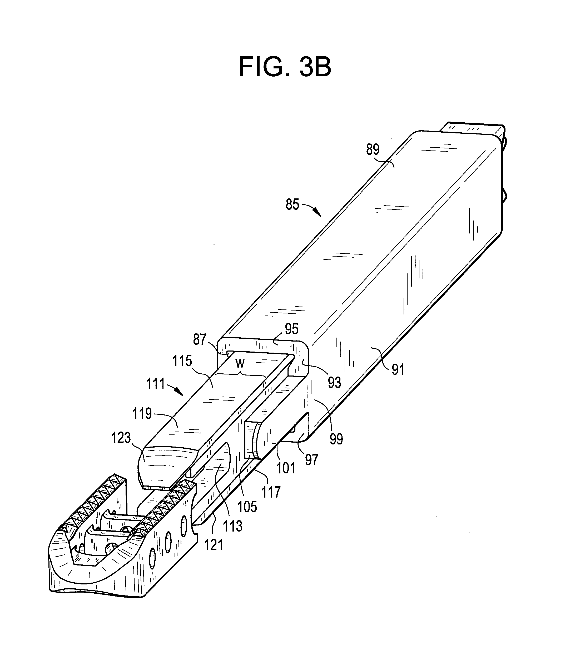
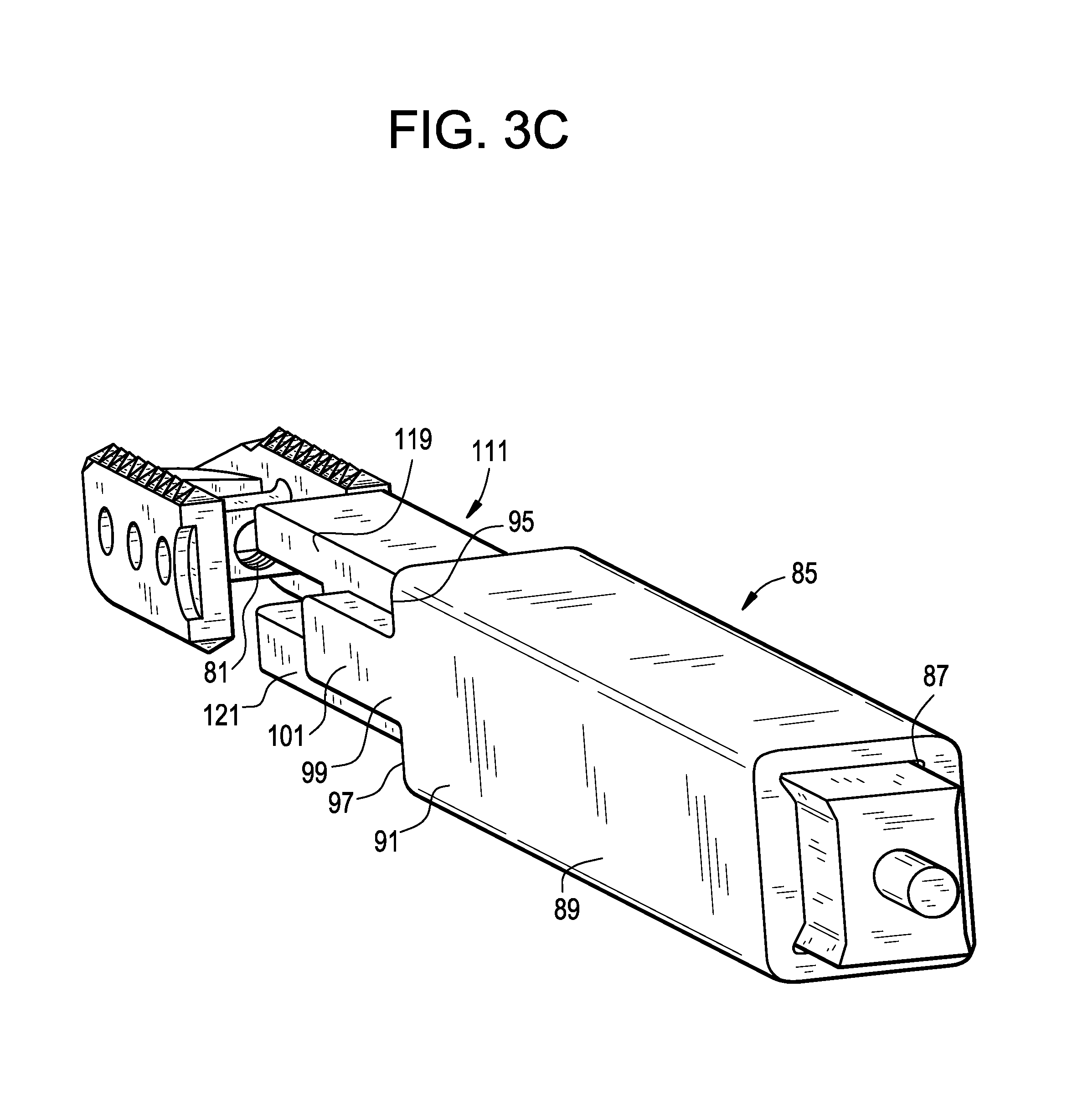
FIGS. 3B-3C are exploded perspective views of a first cage-inserter assembly of the present invention.
FIG. 3D is an assembled perspective view of the first cage-inserter assembly of the present invention.
FIG. 4A is a perspective view of a third embodiment of a cage of the present invention.
FIGS. 4B-4C are exploded perspective views of a second cage-inserter assembly of the present invention.
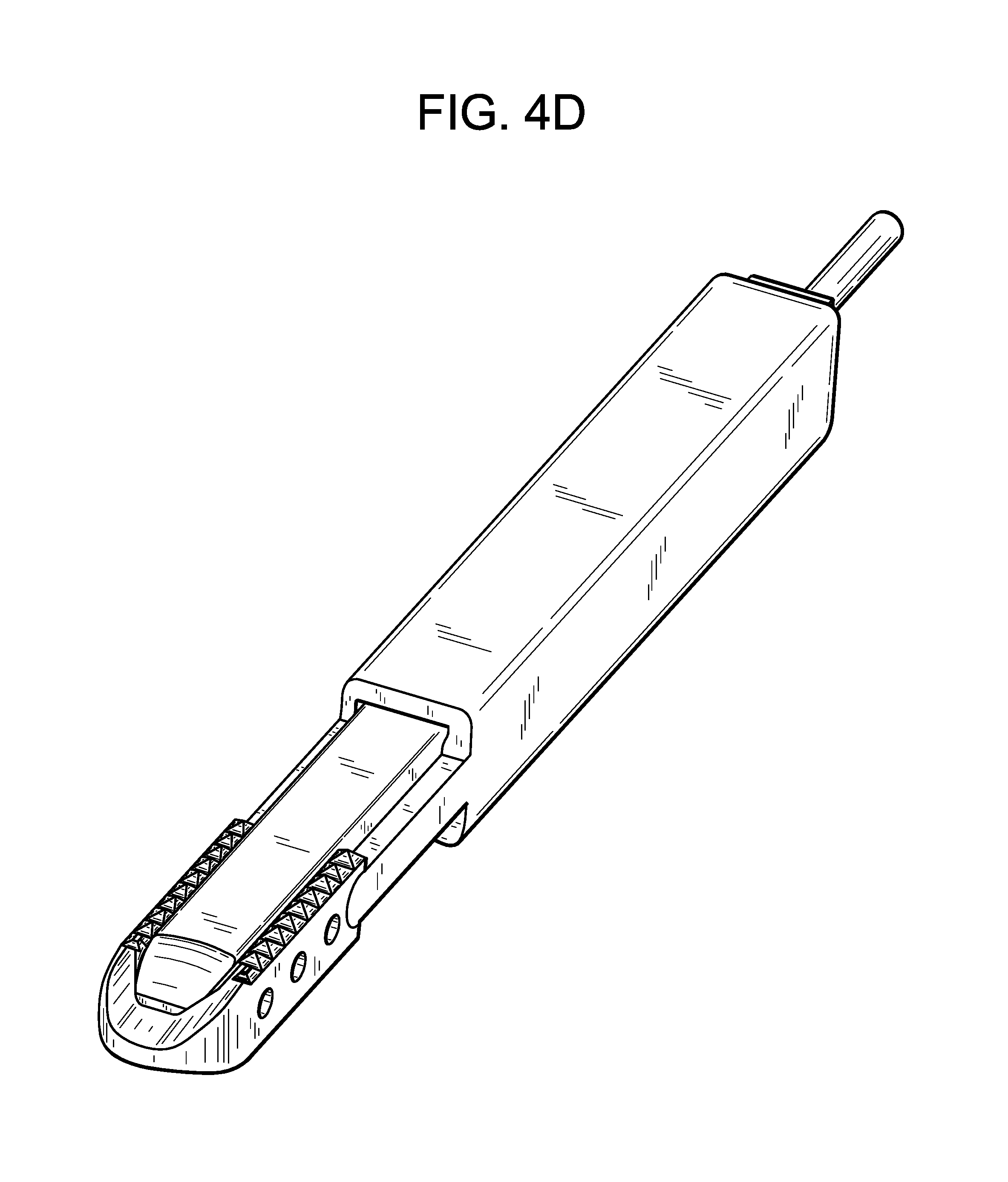
FIG. 4D is an assembled perspective view of the second cage-inserter assembly of the present invention.
FIG. 5A is a perspective view of a fourth embodiment of a cage of the present invention.
FIGS. 5B-5C are exploded perspective views of a third cage-inserter assembly of the present invention.
FIG. 5D is an assembled perspective view of the third cage-inserter assembly of the present invention.
FIGS. 6A-6C are various views of a fourth cage-inserter assembly of the present invention.
FIG. 6D is a perspective view of a leading end component of the present invention.
FIG. 6E is a plan view of a fifth cage-inserter assembly of the present invention.
FIGS. 7A-7C are various views of a planked cage of the present invention.
FIG. 7D is a perspective view of a planked cage-inserter assembly of the present invention.
FIGS. 8A and 8B are views of a planked cage of the present invention.
FIG. 8C is a perspective view of a planked cage-inserter assembly of the present invention.
FIG. 9A is a cross section of a banana cage-inserter assembly of the present invention.
FIG. 9B is a top view of a banana cage-inserter assembly of the present invention.
FIGS. 10A-10B are top views of banana cage-inserter assemblies of the present invention.
DETAILED DESCRIPTION OF THE INVENTION
The present invention relates to a spinal interbody spacer that is easy to insert, fracture resistant, migration resistant, and fillable with a flowable biologic material after insertion.
Now referring to FIGS. 1A-1D, there is provided an intervertebral fusion cage, comprising: a) a leading end 1 having a right 3 and left 5 ends, a front surface 7 and a back surface 9, the back surface being adapted for reception of a rod, b) first 11 and second 13 support members extending backwards from the right and left ends, each member having an upper 15 and lower 17 surface adapted for bearing against and gripping adjacent vertebral bodies and a proximal surface 18, and c) an open trailing end 19 formed between the back surfaces of the support members.
Upon each of the upper and lower surfaces of the cage, there is provided a plurality of teeth 21. When the cage is inserted and the inserter is removed, these teeth bite into the adjacent vertebral bodies and thereby resist migration of the cage.
Each of the support members further comprises a side surface 23 extending between its upper and lower surfaces, each side surface having at least one transverse hole 25 therethrough. The transverse hole allows bone growth therethrough, thereby further securing the cage within the intervertebral space.
In some embodiments, the front surface of the leading end of the cage is tapered. This tapered nose 27 can distract the disc space during its insertion into the disc space, thereby providing for ease of insertion.
Also shown in FIG. 1D, the back surface of the leading end of the cage forms a recess 29 for reception of a rod. In FIGS. 1A-1D, the recess is a throughhole. The throughhole may be threaded. As shown in FIG. 2A, coupling of the back surface of the leading end of the cage with the threaded distal end 33 of the rod 32 allows the surgeon to use the rod as an inserter and insert the cage in a minimally invasive manner. In some embodiments (and as shown in FIGS. 1A-1D), the back surface of the leading end of the cage forms a concave recess for reception of a rod. The concave recess is a simple design choice that provides the needed coupling with the rod and allows the rod to have a substantially rectangular cross-section.
In other embodiments, the back surface of the leading end forms a threaded recess for threadable reception of a rod.
As shown, the ends of the leading end and the support members are integrally connected.
In preferred embodiments, the back surfaces of the support members of the cage are used as stabilizers whereby a forward force upon these back surfaces carefully counterbalances the backward force used to withdraw the rod from the cage. This forward force keeps the cage in the disc space during withdrawal of the rod. Preferably then, the back surfaces are configured to stably receive the laterally-spaced extensions that extend from the distal face of the cannula and provide the biasing forward force. In some embodiments thereof, the back surface of each support member has a concave recess providing such stability. However, in other embodiments, the back surface of each support member may be flat.
In use, the "U" shaped implant of FIG. 1A is coupled with the metal inserter 35 of FIG. 2C so that the metal inserter occupies the interior space of the cage, as shown in FIGS. 2A-2B. Since the inserter is slightly taller than the cage, the smooth upper 37 and lower 39 surfaces of the metal inserter are just proud of the level of the tooth peaks of the cage. These smooth upper and lower surfaces of the metal inserter should therefore be the only part of the assembly that contacts the adjacent vertebral bodies. Therefore, when the implant is inserted, the entire insertion load is borne by the metallic inserter, thereby reducing the chances of damaging the implant. Moreover, since the contact surfaces are smooth, the insertion will be carried out under low friction, thereby increasing the ease of insertion. The cage is then held in place by the extension components 40 of the inserter while the rod component 32 (which is slidably received in annulus 31) is uncoupled from the cage and retracted out of the annulus 31. Annulus 31 is then retracted to a position just outside out of the cage, thereby allowing the adjacent bone to contact the cage. The empty cage is then filled with flowable bone graft by introducing bone graft through the annulus 31.
Therefore, in accordance with the present invention, there is provided an assembly comprising: a) an intervertebral fusion cage having an interior space, and b) a rod adapted to insert the cage into an intervertebral space, the rod having a distal end and an intermediate portion, wherein the distal end of the rod is connected to the cage, and wherein the intermediate portion of the rod is housed within the interior space of the cage.
Also in accordance with the present invention, there is provided a method of inserting a fusion cage, comprising the steps of: a) providing an intervertebral fusion cage having a leading end having a back surface and a trailing end, b) coupling a distal end of an inserter having a slidable rod therein to the back surface of the leading end of the cage, c) inserting the cage into an intervertebral space, d) withdrawing the rod from the cage.
Now referring to FIG. 3A, in a first preferred embodiment, there is provided an intervertebral fusion cage, comprising: a) a leading end 51 having a right 53 and left 55 ends, a front surface 57 and a back surface 59, the back surface being adapted for reception of a rod, b) first 61 and second 63 support members extending backwards from the right and left ends, each member having an upper 65 and lower 67 surface adapted for bearing against and gripping adjacent vertebral bodies, and proximal end surfaces 69, c) an open trailing end 71 formed between the proximal end surfaces, and d) a first 73 and second 75 elongate cross-members, each extending from the first support member to the second support member.
Preferably, as shown, the leading end has an arcuate shape. Also preferably, the leading end has a beveled nose 77 defined by converging upper and lower surfaces. This beveled nose facilitates cage insertion.
Preferably, the upper and lower surfaces of the support members are adapted for gripping the opposing vertebral endplates. Preferably, these surfaces contain outwardly extending teeth 79 that provide stability to the cage.
Preferably, each support member has a throughhole 80 extending therethrough and each cross-member has a throughhole 81 extending therethrough. The cross members provide for substantial containment of the injectable bone graft paste and add stiffness to the construct. These holes are adapted for encouraging bone growth therethrough.
As shown, the cage preferably has a substantially rectangular cross-section.
In this embodiment, an inserter rod can anchor into the back surface of the leading end of the cage.
Therefore, in accordance with the present invention, there is provided an intervertebral fusion cage, comprising: a) a leading end having a right and left ends, a front surface and a back surface, b) first and second support members extending backwards from the right and left ends and terminating in a respective back surface, each member having an upper and lower surface adapted for bearing against and gripping adjacent vertebral bodies, c) an open trailing end formed by the back surfaces of the support members, and d) a strut connecting the first and second support members, the strut being located between the leading end and the open trailing end of the cage, the strut having a back surface being adapted for reception of an inserter rod.
FIGS. 3B and 3C are exploded versions of the cage and inserter assembly, as viewed from the distal and proximal perspectives.
The cage is the cage shown in FIG. 3A. As seen on FIG. 3C, the back surface of the leading end of the cage includes a throughhole 81 adapted for reception of a rod. These holes allow the inserter rod to pass through to the leading end of the cage.
The inserter of FIGS. 3B and 3C includes two components and comprises: a) an outer annulus 85 having a longitudinal throughhole 87, a proximal end portion 89 and a distal end portion 91, the distal end portion including a distal end surface 93 having an upper surface 95, a lower surface 97 and a pair of lateral surfaces 99, each lateral surface having first and second arms 101 extending distally therefrom, each arm having a distal end surface 105 respectively adapted for bearing against a proximal end surface of the cage, b) an inner rod 111 slidable within the longitudinal throughhole of the annulus and having a distal end surface 113, upper 115 and lower 117 surfaces, and upper 119 and lower 121 arms extending from the distal end surface, each arm including a beveled distal end 123 adapted to be coplanar with the beveled nose of the cage, each arm having a width W adapted for slidable reception between the support members of the cage.
Therefore, in accordance with the present invention, there is provided an apparatus for inserting a fusion cage having a leading end and a trailing end, comprising: a) a cannula having a bore therethrough, a distal end face and at least two extensions extending distally from the distal end face, each extensions having a distal end adapted for bearing against the trailing end of the cage, and b) a rod slidably received within the bore of the cannula, the rod having a distal end adapted for bearing against the leading end of the cage.
Also in accordance with the present invention, there is provided an assembly comprising: a) an intervertebral fusion cage having a leading end and a trailing end, and b) an inserter comprising: i) a cannula having a bore therethrough, a distal end face and at least two extensions extending distally from the distal end face, each extension having a distal end bearing against the trailing end of the cage, and ii) a rod slidably received within the bore of the cannula, the rod having a distal end bearing against the leading end of the cage
Lastly, FIG. 3D shows the assembled version of this cage and inserter assembly.
In use, the assembly of FIG. 3D is first constructed. In this assembled state, the arms of the inner rod extend over the cross-members of the cage so that its beveled nose is flush (here, coplanar) with the beveled nose of the cage. The arms of the outer annulus component of the inserter bear against the respective proximal end surfaces of the cage. Next, the distal end of the cage is delivered into the disc space, with the beveled nose of the cage providing distraction of the disc space. The assembly is then moved distally so that the entire cage is within the disc space. Next, the outer annulus of the inserter is held in place as the inner rod component is withdrawn. The bearing of the distal end surface of each arm of the inserter against the proximal end surfaces of the cage during inner rod withdrawal insures that the cage remains in place. Once the inner rod is completely withdrawn, the outer annulus is then moved proximally away from the cage and removed from the patient.
Now referring to FIG. 4A, in a second preferred embodiment, there is provided an intervertebral fusion cage substantially similar to that of FIG. 3A, except that there is a single cross-member 131 connecting the supporting members and it is located in the proximal end portion 135 of the cage. In addition, the throughhole 137 of the cross-member is somewhat larger than that of FIG. 3A (and is adapted for reception of a threaded rod). In some embodiments, injectable graft material is delivered through this throughhole 137.
FIGS. 4B and 4C are exploded versions of the cage and inserter assembly, as viewed from the distal and proximal perspectives. The cage is the cage of FIG. 4A. The inserter assembly is substantially similar to that of FIGS. 3B and 3C, except that the inner rod 141 also has a longitudinal throughhole, and a threaded rod 145 is slidably received within the longitudinal throughhole of the inner rod. The distal end 147 of the threaded rod has a threadform 149 thereon that is adapted to mate with a threadform 149 within the hole 151 in the back surface 153 of the leading end 155 of the cage. The coupling of the threaded rod with the threaded hole on the back surface of the leading end of the cage provides stability for the cage during its insertion into the disc space.
The assembled version of FIGS. 4B and 4C is shown in 4D. Although not shown in FIG. 4D, the threaded distal end of the rod passes through the throughhole of the cross-member of the cage and is received in the threaded hole on the back surface of the leading end of the cage. The coupling of these threadforms provides stability to the cage during insertion. After the cage has been inserted, the threaded rod is disengaged from the threaded hole of the cage. Next, both the threaded rod and the inner rod are simultaneously removed from the disc space, as the outer annulus component of the inserter remains bearing against the proximal ends of the cage to insure that the cage remains in place. Lastly, the outer annulus is removed.
It has further been appreciated that if only the threaded inner rod is removed, then there exists a channel in the insertion instrument through which injectable bone graft material can be injected.
Now referring to FIG. 5A, in a third preferred embodiment, there is provided an intervertebral fusion cage substantially similar to that of FIG. 4A, except that there is no cross-member.
FIGS. 5B and 5C are exploded versions of the cage and inserter assembly, as viewed from the distal and proximal and distal perspectives. The cage is the cage of FIG. 5A. The inserter assembly is substantially similar to that of FIGS. 4B and 4C, except that the arms 161 of the inner rod 163 are substantially shorter. The short arm and lack of cross-member allow the inner rod to bear substantially against the back surface 165 of the leading end 167 of the cage, thereby providing enhanced strength to the assembled design during insertion.
The assembled version of FIGS. 5B and 5C is shown in 5D. The assembled version is used in a manner substantially similar to that of the assembled version shown in 4D.
In some embodiments, hinges are provided between each end of the leading portion of the cage and each of the support members. These hinges allow the cage to be spread after insertion in order to increase the effective surface area (i.e., footprint) covered by the implant. Increasing the footprint beneficially improves the stability of the construct.
Now referring to FIGS. 6A-6D, there is provided an intervertebral fusion cage, comprising: a) a C-shaped leading portion 201 having a first 203 and second 205 ends extending backwards, a front surface 207 and a back surface 209, the back surface having a recess 211 therein adapted for reception of a rod, an upper surface 213 and a lower surface 215, each of the upper and lower surfaces having a groove 217 extending from the front surface to the back surface for reception of a rail 255, 257, and a pivot hole 221 provided in each of the first and second ends that extends from the upper surface to the lower surface, b) first 223 and second 225 support members extending proximally from the first and second ends of the C-shaped leading end, each support member having: i. an upper 227 and lower 229 surface adapted for bearing against and gripping adjacent vertebral bodies, ii. a back surface 231, the back surfaces forming an open trailing end therebetween, iii. a front end 235 having a pivot hole 237 which extends from the upper surface to the lower surface, c) first 239 and second 241 pivot pins respectfully provided in the pivot holes to pivotally connect each end of the C-shaped leading end and the front end of each support member.
Therefore, in accordance with the present invention, there is provided an intervertebral fusion cage, comprising: a) a leading portion having a first and second ends extending backwards, a front surface and a back surface, an upper surface and a lower surface, and a pivot hole provided in each of the ends which extends from the upper surface to the lower surface, b) first and second support members, each support member having: i. an upper and lower surface adapted for bearing against and gripping adjacent vertebral bodies, ii. a back surface, the back surfaces forming an open trailing end therebetween, iii. a front end having a pivot hole which extends from the upper surface of the support member to the lower surface of the support member, and c) first and second pivot pins respectfully provided in the pivot holes to pivotally connect each end of the leading end and the front end of each support member.
Each support member has a bump 245 extending medially from its inside surface 247. As will be explained later in more detail, these bumps facilitate the splaying of the support members to increase the footprint of the cage.
The insertion instrument of the present invention comprises three components; a) a centrally-disposed cylindrical rod 251, b) a pair of laterally disposed cage holders 253, and c) upper 255 and lower 257 rails.
The cylindrical rod is adapted to fit within the open recess formed between the two support members. The rod comprises an enlarged head 259 having an annular recess 261 therebehind, a distal threaded portion 263 and an intermediate portion 265. The annular recess corresponds in shape and dimension to the bumps 245 situated on the inside surfaces of the support members. The distal threaded portion is adapted to be threadably received in the recess of the C-shaped leading portion of the cage, thereby securing the instrument to the cage. The intermediate portion of the rod is housed within the interior space of the cage.
In use, after cage insertion, the threaded portion is unthreaded to free the rod for proximal movement in respect of the cage. When the head of the cylindrical rod is moved backward so as to be removed from the cage, the hinged support members are forced to pivot outwards to increase the footprint of the cage. The closer these bumps are situated to the arcuate leading end of the cage, the greater the splay of the support members. The cylindrical rod is the first instrument component to be removed from the disc space.
The front ends 267 of the upper 255 and lower 257 rails are adapted to fit within the upper and lower grooves provided on the C-shaped leading portion of the cage, while the posterior portion of the rail is adapted to bear against the upper and lower surfaces of the cylindrical rod. Each rail has a thickness T that allows the rail to extend beyond the respective upper and lower surfaces of both the C-shaped leading portion and the support members of the cage. Further, the outer surfaces 271 of the rails are smooth. Because the smooth rails extend beyond the upper and lower surfaces of the cage, they provide a smooth insertion of the cage-instrument assembly into the disc space. For additional ease of insertion, the front end of each rail may be provided with a taper 272 that essentially extends from the taper of the front nose of the C-shaped leading portion of the cage. The rails are the second instrument component to be removed from the disc space.
Therefore, in accordance with the present invention, there is provided an intervertebral fusion cage comprising, a) a leading end and a trailing end, b) first and second longitudinal support members extending between each end, each member having an upper and lower surface adapted for bearing against and gripping adjacent vertebral bodies, each upper and lower surface having a longitudinal groove therein, and c) a plurality of rails, each rail having a smooth outer surface and each rail received in a respective groove of the support member and extending out of the respective groove.
The pair of laterally disposed cage holders are disposed upon each side of the cylindrical rod. Each cage holder has a front end 273 adapted to bear against the back surface of each support member portion of the cage. These front ends prevent the cage from moving back when the cylindrical rod and the rails are removed. The cage holders are the third and last instrument component to be removed from the disc space.
Now referring to FIG. 6E, there is provided an intervertebral fusion cage, comprising: a) a leading end having a right and left ends, a front surface and a back surface, the back surface being adapted for reception of a rod, b) first and second support members 281, each member having a distal end 283 and widened proximal end 285, and an upper and lower surface adapted for bearing against and gripping adjacent vertebral bodies, c) an open trailing end formed between the proximal ends, and d) first and second hinges respectfully provided between each end of the leading end and the distal end of each support member.
As seen in FIG. 6E, each support member has a triangular cross-section. This configuration allows the proximal ends of the support members to extend inward to produce a narrowing at the proximal end. In addition, the inserter that fits within the inner space of the cage has a corresponding triangular shape. Thus, upon retraction of the inserter from the cage, the greater width of the distal end of the inserter pushes the proximal ends of the support members outward, thereby expanding the cross-section of the cage. The enlarged footprint of this expanded design beneficially provides stabilization of the construct. It also beneficially moves the struts towards the more dense bone on the periphery of the endplates.
Now referring to FIGS. 7A-7B, there is provided an implant 301 for promoting bone fusion between adjacent vertebral bodies, said implant having an exterior surface 303, a longitudinal axis and comprising an assembly of components, the components comprising: a) a first strut 305 having a first bone-engaging portion 307, an opposite second bone-engaging portion 309, b) a second strut 311 spaced from said first strut, said second strut having a third bone-engaging portion 313, an opposite fourth bone-engaging portion, said second strut in cooperation with said first strut defining an internal space, wherein the first strut and the second strut each include an aperture opening into the internal space; c) an elongate cross-member 317 extending from the first strut to the second strut and including a first end engaged within the first aperture of the first strut and a second end engaged within the aperture of the second strut; wherein the elongate cross-member is made of a metal.
As shown, FIGS. 7A and 7B also have d) a third strut 306 spaced from said first strut, said second strut having a third bone-engaging portion 308, an opposite fourth bone-engaging portion, said second strut in cooperation with said first strut defining an internal space.
FIG. 7C provides a cage having substantial similarity to the cage of FIGS. 7A and 7B, except that it has a rectangular profile.
In preferred embodiments, the cage of FIG. 7C is constructed from parallel spaced planks made of woven carbon-fiber PEEK laminates spaced apart and held together by titanium pins (or "struts"). The spaces between the planks allow a metal instrument to mate with and attach to the pin component of the implant.
Now referring to FIG. 7D, the metallic insertion instrument (or "inserter") 319 mates to the pins between the PEEK planks to form an assembly that can be easily inserted into and manipulated within the disc space. The inserter has smooth upper 321 and lower 323 surfaces that extend beyond the teeth 325 of the implant to provide for an easy insertion. The inserter also has a bulleted nose 327 to provide distraction. The implant is inserted into the disc space in an orientation that allows the planks to be substantially perpendicular to the patient's vertebral endplates.
The composite nature of this implant in conjunction with the mating condition of the inserter instrument will also allow for very forceful manipulation of the implant during insertion without damaging the implant. In essence, the PEEK laminates are not loaded by the insertion force.
Since the pins 317 are mainly in compression between the inserter components, the inserter will carry the majority of the insertion load. To the extent the pins 317 carry any impaction force, the pins are advantageously made of a high strength, ductile metal such as titanium, and are preferably a titanium alloy, and so can bear such loads. The metallic nature of the pins allows for forceful manipulation of the assembly during insertion into the disc space. At the same time, selection of a somewhat flexible polymer such as PEEK for the material of construction of the laminate components avoids the stress shielding issues associated with purely titanium cage designs. Selection of the woven carbon fiber (as opposed to chopped carbon fiber) will enhance the strength of the PEEK composite.
FIG. 7C shows a cage made of three parallel planks held together by three titanium-based pins. However, in other embodiments, only two planks may be used to construct the cage. Likewise, more than three planks may also be used to construct the cage.
In some embodiments, as in FIG. 7A, the struts 305, 311 can have domed upper and lower surfaces in order to conform to the shape of the vertebral endplates. However, in other embodiments, the upper and lower surfaces of the struts are flat (as in FIG. 7C) and the inserter instrument is provided with a bullet nose 327 that extends distal of the implant (as in FIG. 7D).
In some embodiments, the struts have additional side holes (not shown), wherein those side holes are not engaged by a cross-pin. The presence of these holes will enhance bone ingrowth through the struts.
In some embodiments, the upper and lower surfaces of the struts have a plurality of fine teeth 325 extending therefrom to resist implant migration.
Now referring to FIGS. 8A-8C, there is provided an intervertebral fusion cage, comprising: a) a first strut 351 having first 353 and second 355 sides, an upper bone-engaging portion 357, and a lower bone-engaging portion 359, b) a second strut 361 having first 363 and second 365 sides, said second strut having an upper bone-engaging portion 367, a lower bone-engaging portion, the first side of the second strut opposed to the first side of the first strut thereby defining a first internal space, c) a third strut 371 having first 373 and second 375 sides, said third strut having an upper bone-engaging portion 377, a lower bone-engaging portion, the second side of the second strut opposed to the second side of the third strut thereby defining a second internal space, wherein the first strut, second strut and third strut each include a plurality of apertures extending between the respective first and second sides thereof; wherein the first strut, second strut and third strut each include a first opening 383 adapted for bone growth extending between the respective first and second sides thereof; d) a first elongate cross-member 385 extending from the first strut to the third strut and including a first end 387 engaged within a first aperture of the first strut and a second end 389 engaged within a first aperture of the third strut, and an intermediate portion 391 engaged within a first aperture of the second strut
In some embodiments, the fusion cage includes smooth retractable rails positioned on the top and bottom of the cage. Now referring to FIGS. 9A and 9B, there is provided an intervertebral fusion cage comprising: a) a leading end 401 and a trailing end 403, b) first 405 and second 407 longitudinal support members extending between each end, each member having an upper 409 and a lower 411 surface adapted for bearing against and gripping adjacent vertebral bodies, each upper and lower surface having a longitudinal groove 413 therein, and c) a rail 415 having a smooth outer surface 416 and received in a respective groove and extending out of the respective groove.
As shown in FIG. 9A, the upper and lower surface of the cage has teeth 419 that extend outward to grip the adjacent vertebral bodies. The rails also extend past the respective teeth of each of the upper and lower surfaces. During insertion of this cage, the smooth rails are the only part of the cage that contacts the adjacent vertebral bodies, and so only a moderate insertion force is required to insert the cage into the disc space. Now referring to FIG. 9B, once the cage is set in place, the rails are proximally retracted by the surgeon (while the back end of the cage is still held by the inserter 421), the adjacent boney endplates of the patient collapse upon the cage, and the aggressive teeth of the cage will engage the bone and effectively prevent migration of the implant. Therefore, the cage and inserter of the present invention overcome the prior art problems associated with conventional toothed and smooth cages by not only allowing for easy insertion but also providing a firm, migration-resistant grip.
In some embodiments, the rails are rigid. Such rigid rails may be conveniently used with substantially straight cages. In some embodiments, the rails are flexible. Such flexible rails may be conveniently used with curved cages such as banana cages.
In some embodiments (not shown), the rail comprises an outer tube having a smooth outer surface and an inner rod. When assembled, the tube and rod have a height that allows the to extend outward past the upper and lower teeth of the cage. During insertion, the tube-rod assembly eases insertion load. When the cage has been inserted, the rod is withdrawn and the tube collapses under the force of the tensioning load of the functional spinal unit. Thus, the adjacent boney endplates of the patient collapse upon the cage, and the aggressive teeth of the cage will engage the bone and effectively prevent migration of the implant.
In some embodiments (not shown), the rails can be molded onto the cage as a fast dissolving polymer. During insertion, the smooth rails ease insertion. Once the cage is set in place, the rails dissolve, thereby allowing the adjacent boney endplates of the patient to collapse upon the cage.
In some embodiments, a single smooth cable may act as both an upper and lower rail by wrapping around an end of the cage. During insertion, the smooth rails ease insertion. At this time, tensioning of the cable may serve to hold the cage on the inserter.
Once the cage is set in place, the surgeon pulls a single end of the cable in order to remove the whole cable from the cage. In some embodiments, the cable is coated with a smoothing polymer such as Teflon in order to reduce friction.
The recognition that inserter designs can now occupy the interior volume of the cage has special application in the field of intervertebral fusion cages having a banana shape. In these banana cages, the cage can be made to attach to an inserter at the midpoint of the cage, which is the strongest portion of the cage.
Now referring to FIG. 10A, there is provided an intervertebral fusion cage having: a) a convex anterior surface 451 and a concave posterior surface 453, b) an upper bone engaging surface 455 and a lower bone engaging surface (not shown), c) leading 459 and trailing 461 side surfaces, d) a strut 463 connecting the convex anterior surface and the concave posterior surface and thereby forming leading 464 and trailing 466 spaces, wherein the strut has a threaded recess opening 465 onto the trailing space for reception of a threaded distal end of an inserter and, wherein the trailing side surface has a throughhole 467 therethrough for slidable reception of the inserter.
Now referring to FIG. 10B, there is provided an intervertebral fusion cage having substantial similarity to that of FIG. 10A, except that its leading side surface also has a throughhole 469 adapted for slidable reception of a rail.
Typically, the inserter of the present invention can be made out of any material commonly used in medical instruments. If the inserter is designed to be reusable, then it is preferred that all of its components be made of stainless steel. If the device is designed to be disposable, then it is preferred that at least some of the components be made of plastic. Preferably, at least one component of the inserter is sterilized. More preferably, each component is sterilized.
The intervertebral fusion cage of the present invention may be manufactured from any biocompatible material commonly used in interbody fusion procedures. In some embodiments, the cage is made from a composite comprising 40-99% polyarylethyl ketone PAEK, and 1-60% carbon fiber. Such a cage is radiolucent. Preferably, the polyarylethyl ketone PAEK is selected from the group consisting of polyetherether ketone PEEK, polyether ketone ketone PEKK, polyether ketone ether ketone ketone PEKEKK, and polyether ketone PEK. Preferably, cage is made from woven, long carbon fiber laminates. Preferably, the PAEK and carbon fiber are homogeneously mixed. Preferably, the composite consists essentially of PAEK and carbon fiber. Preferably, the composite comprises 60-80 wt % PAEK and 20-40 wt % carbon fiber, more preferably 65-75 wt % PAEK and 25-35 wt % carbon fiber. In some embodiments, the cage is made from materials used in carbon fibers cages marketed by DePuy Spine, Raynham, Mass., USA. In some embodiments, the composite is PEEK-OPTIMA.TM., available from Invibio of Greenville, N.C.
In other embodiments, the cage is made from a metal such as titanium alloy, such as Ti-6Al-4. In other embodiments, the cage is made from an allograft material. In some embodiments, the cage is made from ceramic, preferably a ceramic that can be at least partially resorbed, such as HA or TCP. In other embodiments, the ceramic comprises an oxide such as either alumina or zirconia. In some embodiments, the cage is made from a polymer, preferably a polymer that can be at least partially resorbed, such as PLA or PLG.
In preferred embodiments, the cage is provided in a sterile form.
In summary, the cage implant of the present invention distracts the disc space during insertion. It is easy to insert and optimizes clinical performance once in place because it resists migration and subsidence, has an appropriate stiffness for load sharing, is preferably radiolucent and has a shape that is able to contain injected graft material such as growth factors. In addition, the cage is robust over a wide variation of surgical technique because it will not break even when large forces are applied thereto.
The cage of the present invention is compatible with the broad use of injectable paste-like bone grafting materials, such as BMP-containing pastes because it is designed to be inserted empty and then filled with graft in-situ. With the availability of these injectable pastes, cages will no longer require large, contiguous internal volumes to accept morselized/granular bone graft. Spaces can be smaller and more numerous.
The cage of the present invention allows an insertion instrument to occupy the internal volume of the cage so as to minimize the overall size of the inserted cage as well as to bear insertion loads. The inserter can also possess smooth upper and lower surfaces to reduce friction and thereby increase the ease of insertion. The cage of the present invention will not experience large loads during insertion.
* * * * *
D00000
D00001
D00002
D00003
D00004
D00005
D00006
D00007
D00008
D00009
D00010
D00011
D00012

D00013
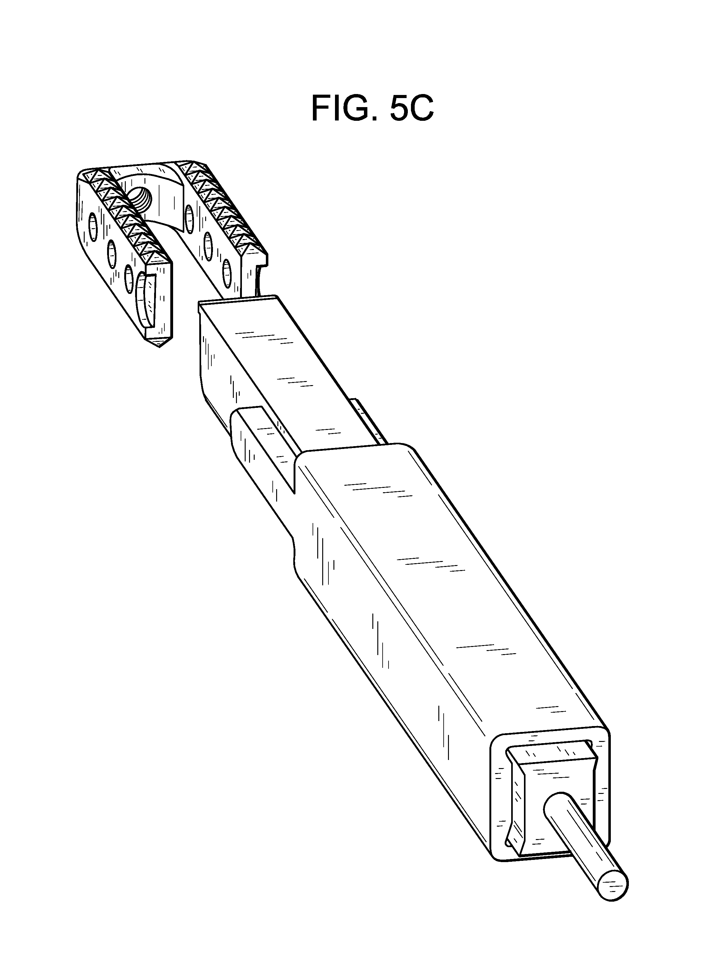
D00014

D00015

D00016

D00017

D00018

D00019

D00020
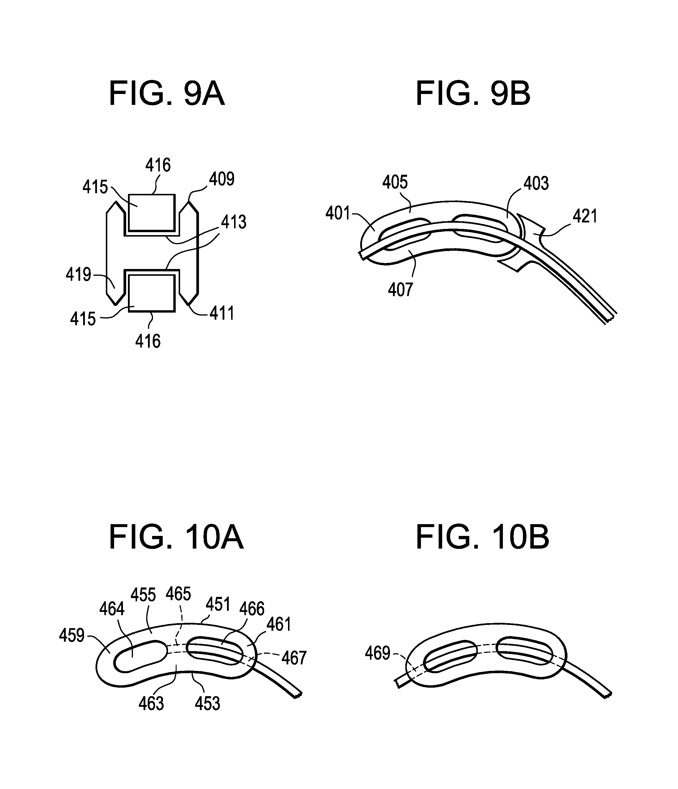
XML
uspto.report is an independent third-party trademark research tool that is not affiliated, endorsed, or sponsored by the United States Patent and Trademark Office (USPTO) or any other governmental organization. The information provided by uspto.report is based on publicly available data at the time of writing and is intended for informational purposes only.
While we strive to provide accurate and up-to-date information, we do not guarantee the accuracy, completeness, reliability, or suitability of the information displayed on this site. The use of this site is at your own risk. Any reliance you place on such information is therefore strictly at your own risk.
All official trademark data, including owner information, should be verified by visiting the official USPTO website at www.uspto.gov. This site is not intended to replace professional legal advice and should not be used as a substitute for consulting with a legal professional who is knowledgeable about trademark law.