Magnetic connector
Kiani , et al. Feb
U.S. patent number 10,205,272 [Application Number 15/288,987] was granted by the patent office on 2019-02-12 for magnetic connector. This patent grant is currently assigned to Masimo Corporation. The grantee listed for this patent is MASIMO CORPORATION. Invention is credited to Cristiano Dalvi, Massi Joe E. Kiani, Marcelo M. Lamego, Hung Vo.


View All Diagrams
| United States Patent | 10,205,272 |
| Kiani , et al. | February 12, 2019 |
Magnetic connector
Abstract
A magnetic connector has a receptacle and a plug. The receptacle has an electromagnet comprising an inner core, an outer core, a coil disposed around the inner core and an air gap defined by the edges of the inner and outer cores. The plug has a plug core and an anchor defined by the plug core edge. The anchor is configured to insert into the air gap as a receptacle socket electrically connects with plug pins. The coil is energized and de-energized so as to assist in the insertion or removal of the anchor from within the air gap and the corresponding connection and disconnection of the socket and pins.
| Inventors: | Kiani; Massi Joe E. (Laguna Niguel, CA), Lamego; Marcelo M. (Coto De Caza, CA), Dalvi; Cristiano (Irvine, CA), Vo; Hung (Garden Grove, CA) | ||||||||||
|---|---|---|---|---|---|---|---|---|---|---|---|
| Applicant: |
|
||||||||||
| Assignee: | Masimo Corporation (Irvine,
CA) |
||||||||||
| Family ID: | 42731083 | ||||||||||
| Appl. No.: | 15/288,987 | ||||||||||
| Filed: | October 7, 2016 |
Prior Publication Data
| Document Identifier | Publication Date | |
|---|---|---|
| US 20170187146 A1 | Jun 29, 2017 | |
Related U.S. Patent Documents
| Application Number | Filing Date | Patent Number | Issue Date | ||
|---|---|---|---|---|---|
| 13783424 | Mar 4, 2013 | 9466919 | |||
| 12721199 | Mar 5, 2013 | 8388353 | |||
| 61159336 | Mar 11, 2009 | ||||
| Current U.S. Class: | 1/1 |
| Current CPC Class: | A61B 5/14551 (20130101); A61B 5/02055 (20130101); H01R 13/6591 (20130101); A61B 5/6826 (20130101); H01R 13/7037 (20130101); H01R 13/6205 (20130101); A61B 5/14546 (20130101); H01R 11/30 (20130101); Y10S 439/95 (20130101); H01R 2201/12 (20130101); H01R 13/631 (20130101); Y10T 29/49117 (20150115); H01R 13/7175 (20130101) |
| Current International Class: | A61B 5/02 (20060101); H01R 13/703 (20060101); H01R 11/30 (20060101); H01R 13/62 (20060101); A61B 5/0205 (20060101); A61B 5/145 (20060101); A61B 5/1455 (20060101); A61B 5/00 (20060101); H01R 13/6591 (20110101); H01R 13/717 (20060101) |
| Field of Search: | ;600/476,486,309,585 ;439/39,950 |
References Cited [Referenced By]
U.S. Patent Documents
| 3534310 | October 1970 | Pelissier |
| 4211456 | July 1980 | Sears |
| 4605268 | August 1986 | Meador |
| 4669792 | June 1987 | Kjeldstad |
| 4838797 | June 1989 | Dodier |
| 4874316 | October 1989 | Kamon et al. |
| 4960128 | October 1990 | Gordon et al. |
| 4964408 | October 1990 | Hink et al. |
| 5041187 | August 1991 | Hink et al. |
| 5069213 | December 1991 | Polczynski |
| 5163438 | November 1992 | Gordon et al. |
| 5319355 | June 1994 | Russek |
| 5337744 | August 1994 | Branigan |
| 5341805 | August 1994 | Stavridi et al. |
| D353195 | December 1994 | Savage et al. |
| D353196 | December 1994 | Savage et al. |
| 5377676 | January 1995 | Vari et al. |
| D359546 | June 1995 | Savage et al. |
| 5431170 | July 1995 | Mathews |
| D361840 | August 1995 | Savage et al. |
| D362063 | September 1995 | Savage et al. |
| 5452717 | September 1995 | Branigan et al. |
| D363120 | October 1995 | Savage et al. |
| 5456252 | October 1995 | Vari et al. |
| 5479934 | January 1996 | Imran |
| 5482036 | January 1996 | Diab et al. |
| 5490505 | February 1996 | Diab et al. |
| 5494043 | February 1996 | O'Sullivan et al. |
| 5533511 | July 1996 | Kaspari et al. |
| 5534851 | July 1996 | Russek |
| 5561275 | October 1996 | Savage et al. |
| 5562002 | October 1996 | Lalin |
| 5568815 | October 1996 | Raynes |
| 5590649 | January 1997 | Caro et al. |
| 5602924 | February 1997 | Durand et al. |
| 5632272 | May 1997 | Diab et al. |
| 5638816 | June 1997 | Kiani-Azarbayjany et al. |
| 5638818 | June 1997 | Diab et al. |
| 5645440 | July 1997 | Tobler et al. |
| 5685299 | November 1997 | Diab et al. |
| D393830 | April 1998 | Tobler et al. |
| 5743262 | April 1998 | Lepper, Jr. et al. |
| 5758644 | June 1998 | Diab et al. |
| 5760910 | June 1998 | Lepper, Jr. et al. |
| 5769785 | June 1998 | Diab et al. |
| 5782757 | July 1998 | Diab et al. |
| 5785659 | July 1998 | Caro et al. |
| 5791347 | August 1998 | Flaherty et al. |
| 5810734 | September 1998 | Caro et al. |
| 5823950 | October 1998 | Diab et al. |
| 5830131 | November 1998 | Caro et al. |
| 5833618 | November 1998 | Caro et al. |
| 5860919 | January 1999 | Kiani-Azarbayjany et al. |
| 5890929 | April 1999 | Mills et al. |
| 5904654 | May 1999 | Wohltmann et al. |
| 5919134 | July 1999 | Diab |
| 5934925 | August 1999 | Tobler et al. |
| 5940182 | August 1999 | Lepper, Jr. et al. |
| 5941729 | August 1999 | Sri-Jayantha |
| 5995855 | November 1999 | Kiani et al. |
| 5997343 | December 1999 | Mills et al. |
| 6002952 | December 1999 | Diab et al. |
| 6011986 | January 2000 | Diab et al. |
| 6027452 | February 2000 | Flaherty et al. |
| 6030229 | February 2000 | Tsutsui |
| 6036642 | March 2000 | Diab et al. |
| 6045509 | April 2000 | Caro et al. |
| 6067462 | May 2000 | Diab et al. |
| 6081735 | June 2000 | Diab et al. |
| 6088607 | July 2000 | Diab et al. |
| 6110522 | August 2000 | Lepper, Jr. et al. |
| 6124597 | September 2000 | Shehada |
| 6128521 | October 2000 | Marro et al. |
| 6129675 | October 2000 | Jay |
| 6144868 | November 2000 | Parker |
| 6151516 | November 2000 | Kiani-Azarbayjany et al. |
| 6152754 | November 2000 | Gerhardt et al. |
| 6157850 | December 2000 | Diab et al. |
| 6165005 | December 2000 | Mills et al. |
| 6184521 | February 2001 | Coffin, IV et al. |
| 6206830 | March 2001 | Diab et al. |
| 6229856 | May 2001 | Diab et al. |
| 6232609 | May 2001 | Snyder et al. |
| 6236872 | May 2001 | Diab et al. |
| 6241683 | June 2001 | Macklem et al. |
| 6253097 | June 2001 | Aronow et al. |
| 6256523 | July 2001 | Diab et al. |
| 6263222 | July 2001 | Diab et al. |
| 6278522 | August 2001 | Lepper, Jr. et al. |
| 6280213 | August 2001 | Tobler et al. |
| 6285896 | September 2001 | Tobler et al. |
| 6301493 | October 2001 | Marro et al. |
| 6317627 | November 2001 | Ennen et al. |
| 6321100 | November 2001 | Parker |
| 6325761 | December 2001 | Jay |
| 6334065 | December 2001 | Al-Ali et al. |
| 6343224 | January 2002 | Parker |
| 6349228 | February 2002 | Kiani et al. |
| 6360114 | March 2002 | Diab et al. |
| 6368283 | April 2002 | Xu et al. |
| 6371921 | April 2002 | Caro et al. |
| 6377829 | April 2002 | Al-Ali |
| 6388240 | May 2002 | Schulz et al. |
| 6397091 | May 2002 | Diab et al. |
| 6430437 | August 2002 | Marro |
| 6430525 | August 2002 | Weber et al. |
| 6463311 | October 2002 | Diab |
| 6470199 | October 2002 | Kopotic et al. |
| 6501975 | December 2002 | Diab et al. |
| 6505059 | January 2003 | Kollias et al. |
| 6515273 | February 2003 | Al-Ali |
| 6519487 | February 2003 | Parker |
| 6525386 | February 2003 | Mills et al. |
| 6526300 | February 2003 | Kiani et al. |
| 6541756 | April 2003 | Schulz et al. |
| 6542764 | April 2003 | Al-Ali et al. |
| 6565363 | May 2003 | Downing |
| 6580086 | June 2003 | Schulz et al. |
| 6584336 | June 2003 | Ali et al. |
| 6595316 | July 2003 | Cybulski et al. |
| 6597932 | July 2003 | Tian et al. |
| 6597933 | July 2003 | Kiani et al. |
| 6606511 | August 2003 | Ali et al. |
| 6632181 | October 2003 | Flaherty et al. |
| 6639668 | October 2003 | Trepagnier |
| 6640116 | October 2003 | Diab |
| 6643530 | November 2003 | Diab et al. |
| 6650917 | November 2003 | Diab et al. |
| 6654624 | November 2003 | Diab et al. |
| 6658276 | December 2003 | Kiani et al. |
| 6661161 | December 2003 | Lanzo et al. |
| 6671531 | December 2003 | Al-Ali et al. |
| 6678543 | January 2004 | Diab et al. |
| 6684090 | January 2004 | Ali et al. |
| 6684091 | January 2004 | Parker |
| 6697656 | February 2004 | Al-Ali |
| 6697657 | February 2004 | Shehada et al. |
| 6697658 | February 2004 | Al-Ali |
| RE38476 | March 2004 | Diab et al. |
| 6699194 | March 2004 | Diab et al. |
| 6714804 | March 2004 | Al-Ali et al. |
| RE38492 | April 2004 | Diab et al. |
| 6721582 | April 2004 | Trepagnier et al. |
| 6721585 | April 2004 | Parker |
| 6725075 | April 2004 | Al-Ali |
| 6728560 | April 2004 | Kollias et al. |
| 6735459 | May 2004 | Parker |
| 6745060 | June 2004 | Diab et al. |
| 6760607 | July 2004 | Al-Ali |
| 6770028 | August 2004 | Ali et al. |
| 6771994 | August 2004 | Kiani et al. |
| 6792300 | September 2004 | Diab et al. |
| 6813511 | November 2004 | Diab et al. |
| 6816741 | November 2004 | Diab |
| 6822564 | November 2004 | Al-Ali |
| 6826419 | November 2004 | Diab et al. |
| 6830711 | December 2004 | Mills et al. |
| 6850787 | February 2005 | Weber et al. |
| 6850788 | February 2005 | Al-Ali |
| 6852083 | February 2005 | Caro et al. |
| 6861639 | March 2005 | Al-Ali |
| 6897370 | May 2005 | Kondo |
| 6898452 | May 2005 | Al-Ali et al. |
| 6920345 | July 2005 | Al-Ali et al. |
| 6931268 | August 2005 | Kiani-Azarbayjany et al. |
| 6934570 | August 2005 | Kiani et al. |
| 6939305 | September 2005 | Flaherty et al. |
| 6943348 | September 2005 | Coffin, IV |
| 6950687 | September 2005 | Al-Ali |
| 6961598 | November 2005 | Diab |
| 6970792 | November 2005 | Diab |
| 6979812 | December 2005 | Al-Ali |
| 6985764 | January 2006 | Mason et al. |
| 6993371 | January 2006 | Kiani et al. |
| 6996427 | February 2006 | Ali et al. |
| 6999904 | February 2006 | Weber et al. |
| 7003338 | February 2006 | Weber et al. |
| 7003339 | February 2006 | Diab et al. |
| 7015451 | March 2006 | Dalke et al. |
| 7024233 | April 2006 | Ali et al. |
| 7027849 | April 2006 | Al-Ali |
| 7030749 | April 2006 | Al-Ali |
| 7039449 | May 2006 | Al-Ali |
| 7041060 | May 2006 | Flaherty et al. |
| 7044918 | May 2006 | Diab |
| 7067893 | June 2006 | Mills et al. |
| 7096052 | August 2006 | Mason et al. |
| 7096054 | August 2006 | Abdul-Hafiz et al. |
| 7097461 | August 2006 | Neidlein |
| 7132641 | November 2006 | Schulz et al. |
| 7142901 | November 2006 | Kiani et al. |
| 7149561 | December 2006 | Diab |
| 7186966 | March 2007 | Al-Ali |
| 7190261 | March 2007 | Al-Ali |
| 7204695 | April 2007 | Shiu et al. |
| 7215984 | May 2007 | Diab |
| 7215986 | May 2007 | Diab |
| 7221971 | May 2007 | Diab |
| 7225006 | May 2007 | Al-Ali et al. |
| 7225007 | May 2007 | Al-Ali |
| RE39672 | June 2007 | Shehada et al. |
| 7239905 | July 2007 | Kiani-Azarbayjany et al. |
| 7245953 | July 2007 | Parker |
| 7252512 | August 2007 | Tai et al. |
| 7252565 | August 2007 | Hunter |
| 7254429 | August 2007 | Schurman et al. |
| 7254431 | August 2007 | Al-Ali |
| 7254433 | August 2007 | Diab et al. |
| 7254434 | August 2007 | Schulz et al. |
| 7272425 | September 2007 | Al-Ali |
| 7274955 | September 2007 | Kiani et al. |
| D554263 | October 2007 | Al-Ali |
| 7280858 | October 2007 | Al-Ali et al. |
| 7289835 | October 2007 | Mansfield et al. |
| 7292883 | November 2007 | De Felice et al. |
| 7295866 | November 2007 | Al-Ali |
| 7311526 | December 2007 | Rohrbach et al. |
| 7328053 | February 2008 | Diab et al. |
| 7332784 | February 2008 | Mills et al. |
| 7340287 | March 2008 | Mason et al. |
| 7341458 | March 2008 | Koh |
| 7341559 | March 2008 | Schulz et al. |
| 7343186 | March 2008 | Lamego et al. |
| D566282 | April 2008 | Al-Ali et al. |
| 7351066 | April 2008 | DiFonzo et al. |
| 7355512 | April 2008 | Al-Ali |
| 7356365 | April 2008 | Schurman |
| 7364433 | April 2008 | Neidlein |
| 7371981 | May 2008 | Abdul-Hafiz |
| 7373193 | May 2008 | Al-Ali et al. |
| 7373194 | May 2008 | Weber et al. |
| 7376453 | May 2008 | Diab et al. |
| 7377794 | May 2008 | Al Ali et al. |
| 7377899 | May 2008 | Weber et al. |
| 7383070 | June 2008 | Diab et al. |
| 7415297 | August 2008 | Al-Ali et al. |
| 7428432 | September 2008 | Ali et al. |
| 7438683 | October 2008 | Al-Ali et al. |
| 7440787 | October 2008 | Diab |
| 7445452 | November 2008 | Wu |
| 7454240 | November 2008 | Diab et al. |
| 7467002 | December 2008 | Weber et al. |
| 7469157 | December 2008 | Diab et al. |
| 7471969 | December 2008 | Diab et al. |
| 7471971 | December 2008 | Diab et al. |
| 7483729 | January 2009 | Al-Ali et al. |
| 7483730 | January 2009 | Diab et al. |
| 7489958 | February 2009 | Diab et al. |
| 7496391 | February 2009 | Diab et al. |
| 7496393 | February 2009 | Diab et al. |
| D587657 | March 2009 | Al-Ali et al. |
| 7499741 | March 2009 | Diab et al. |
| 7499835 | March 2009 | Weber et al. |
| 7500950 | March 2009 | Al-Ali et al. |
| 7509154 | March 2009 | Diab et al. |
| 7509494 | March 2009 | Al-Ali |
| 7510849 | March 2009 | Schurman et al. |
| 7526328 | April 2009 | Diab et al. |
| 7530942 | May 2009 | Diab |
| 7530949 | May 2009 | Al Ali et al. |
| 7530955 | May 2009 | Diab et al. |
| 7563110 | July 2009 | Al-Ali et al. |
| 7596398 | September 2009 | Al-Ali et al. |
| 7618375 | November 2009 | Flaherty |
| D606659 | December 2009 | Kiani et al. |
| 7625213 | December 2009 | Tse |
| 7647083 | January 2010 | Al-Ali et al. |
| D609193 | February 2010 | Al-Ali et al. |
| D614305 | April 2010 | Al-Ali et al. |
| RE41317 | May 2010 | Parker |
| 7729733 | June 2010 | Al-Ali et al. |
| 7734320 | June 2010 | Al-Ali |
| 7761127 | July 2010 | Al-Ali et al. |
| 7761128 | July 2010 | Al-Ali et al. |
| 7764982 | July 2010 | Dalke et al. |
| D621516 | August 2010 | Kiani et al. |
| 7791155 | September 2010 | Diab |
| 7801581 | September 2010 | Diab |
| 7822452 | October 2010 | Schurman et al. |
| RE41912 | November 2010 | Parker |
| 7844313 | November 2010 | Kiani et al. |
| 7844314 | November 2010 | Al-Ali |
| 7844315 | November 2010 | Al-Ali |
| 7865222 | January 2011 | Weber et al. |
| 7873497 | January 2011 | Weber et al. |
| 7880606 | February 2011 | Al-Ali |
| 7880626 | February 2011 | Al-Ali et al. |
| 7891355 | February 2011 | Al-Ali et al. |
| 7894868 | February 2011 | Al-Ali et al. |
| 7899507 | March 2011 | Al-Ali et al. |
| 7899518 | March 2011 | Trepagnier et al. |
| 7904132 | March 2011 | Weber et al. |
| 7909772 | March 2011 | Popov et al. |
| 7910875 | March 2011 | Al-Ali |
| 7919713 | April 2011 | Al-Ali et al. |
| 7937128 | May 2011 | Al-Ali |
| 7937129 | May 2011 | Mason et al. |
| 7937130 | May 2011 | Diab et al. |
| 7941199 | May 2011 | Kiani |
| 7951086 | May 2011 | Flaherty et al. |
| 7957780 | June 2011 | Lamego et al. |
| 7962188 | June 2011 | Kiani et al. |
| 7962190 | June 2011 | Diab et al. |
| 7963774 | June 2011 | Shiff et al. |
| 7976472 | July 2011 | Kiani |
| 7988637 | August 2011 | Diab |
| 7990382 | August 2011 | Kiani |
| 7991446 | August 2011 | Al-Ali et al. |
| 8000761 | August 2011 | Al-Ali |
| 8008088 | August 2011 | Bellott et al. |
| RE42753 | September 2011 | Kiani-Azarbayjany et al. |
| 8019400 | September 2011 | Diab et al. |
| 8028701 | October 2011 | Al-Ali et al. |
| 8029765 | October 2011 | Bellott et al. |
| 8036727 | October 2011 | Schurman et al. |
| 8036728 | October 2011 | Diab et al. |
| 8046040 | October 2011 | Ali et al. |
| 8046041 | October 2011 | Diab et al. |
| 8046042 | October 2011 | Diab et al. |
| 8048040 | November 2011 | Kiani |
| 8050728 | November 2011 | Al-Ali et al. |
| RE43169 | February 2012 | Parker |
| 8118620 | February 2012 | Al-Ali et al. |
| 8126528 | February 2012 | Diab et al. |
| 8128572 | March 2012 | Diab et al. |
| 8130105 | March 2012 | Al-Ali et al. |
| 8145287 | March 2012 | Diab et al. |
| 8150487 | April 2012 | Diab et al. |
| 8175672 | May 2012 | Parker |
| 8180420 | May 2012 | Diab et al. |
| 8182443 | May 2012 | Kiani |
| 8185180 | May 2012 | Diab et al. |
| 8187195 | May 2012 | Tulkki |
| 8190223 | May 2012 | Al-Ali et al. |
| 8190227 | May 2012 | Diab et al. |
| 8203438 | June 2012 | Kiani et al. |
| 8203704 | June 2012 | Merritt et al. |
| 8204566 | June 2012 | Schurman et al. |
| 8219172 | July 2012 | Schurman et al. |
| 8224411 | July 2012 | Al-Ali et al. |
| 8228181 | July 2012 | Al-Ali |
| 8229533 | July 2012 | Diab et al. |
| 8233955 | July 2012 | Al-Ali et al. |
| 8244325 | August 2012 | Al-Ali et al. |
| 8255026 | August 2012 | Al-Ali |
| 8255027 | August 2012 | Al-Ali et al. |
| 8255028 | August 2012 | Al-Ali et al. |
| 8260577 | September 2012 | Weber et al. |
| 8265723 | September 2012 | McHale et al. |
| 8274360 | September 2012 | Sampath et al. |
| 8301217 | October 2012 | Al-Ali et al. |
| 8306596 | November 2012 | Schurman et al. |
| 8310336 | November 2012 | Muhsin et al. |
| 8315683 | November 2012 | Al-Ali et al. |
| RE43860 | December 2012 | Parker |
| 8337403 | December 2012 | Al-Ali et al. |
| 8346330 | January 2013 | Lamego |
| 8353842 | January 2013 | Al-Ali et al. |
| 8355766 | January 2013 | MacNeish, III et al. |
| 8359080 | January 2013 | Diab et al. |
| 8364223 | January 2013 | Al-Ali et al. |
| 8364226 | January 2013 | Diab et al. |
| 8374665 | February 2013 | Lamego |
| 8385995 | February 2013 | Al-ali et al. |
| 8385996 | February 2013 | Smith et al. |
| 8388353 | March 2013 | Kiani et al. |
| 8399822 | March 2013 | Al-Ali |
| 8401602 | March 2013 | Kiani |
| 8405608 | March 2013 | Al-Ali et al. |
| 8414499 | April 2013 | Al-Ali et al. |
| 8418524 | April 2013 | Al-Ali |
| 8423106 | April 2013 | Lamego et al. |
| 8428967 | April 2013 | Olsen et al. |
| 8430817 | April 2013 | Al-Ali et al. |
| 8437825 | May 2013 | Dalvi et al. |
| 8455290 | June 2013 | Siskavich |
| 8457703 | June 2013 | Al-Ali |
| 8457707 | June 2013 | Kiani |
| 8463349 | June 2013 | Diab et al. |
| 8466286 | June 2013 | Bellot et al. |
| 8471713 | June 2013 | Poeze et al. |
| 8473020 | June 2013 | Kiani et al. |
| 8483787 | July 2013 | Al-Ali et al. |
| 8489364 | July 2013 | Weber et al. |
| 8497753 | July 2013 | DiFonzo |
| 8498684 | July 2013 | Weber et al. |
| 8504128 | August 2013 | Blank et al. |
| 8509867 | August 2013 | Workman et al. |
| 8515509 | August 2013 | Bruinsma et al. |
| 8523781 | September 2013 | Al-Ali |
| 8529301 | September 2013 | Al-Ali et al. |
| 8532727 | September 2013 | Ali et al. |
| 8532728 | September 2013 | Diab et al. |
| D692145 | October 2013 | Al-Ali et al. |
| 8547209 | October 2013 | Kiani et al. |
| 8548548 | October 2013 | Al-Ali |
| 8548549 | October 2013 | Schurman et al. |
| 8548550 | October 2013 | Al-Ali et al. |
| 8560032 | October 2013 | Al-Ali et al. |
| 8560034 | October 2013 | Diab et al. |
| 8570167 | October 2013 | Al-Ali |
| 8570503 | October 2013 | Vo et al. |
| 8571617 | October 2013 | Reichgott et al. |
| 8571618 | October 2013 | Lamego et al. |
| 8571619 | October 2013 | Al-Ali et al. |
| 8577431 | November 2013 | Lamego et al. |
| 8581732 | November 2013 | Al-Ali et al. |
| 8584345 | November 2013 | Al-Ali et al. |
| 8588880 | November 2013 | Abdul-Hafiz et al. |
| 8600467 | December 2013 | Al-Ali et al. |
| 8606342 | December 2013 | Diab |
| 8626255 | January 2014 | Al-Ali et al. |
| 8630691 | January 2014 | Lamego et al. |
| 8634889 | January 2014 | Al-Ali et al. |
| 8641631 | February 2014 | Sierra et al. |
| 8652060 | February 2014 | Al-Ali |
| 8663107 | March 2014 | Kiani |
| 8666468 | March 2014 | Al-Ali |
| 8667967 | March 2014 | Al- Ali et al. |
| 8670811 | March 2014 | O'Reilly |
| 8670814 | March 2014 | Diab et al. |
| 8676286 | March 2014 | Weber et al. |
| 8682407 | March 2014 | Al-Ali |
| RE44823 | April 2014 | Parker |
| RE44875 | April 2014 | Kiani et al. |
| 8690799 | April 2014 | Telfort et al. |
| 8700112 | April 2014 | Kiani |
| 8702627 | April 2014 | Telfort et al. |
| 8706179 | April 2014 | Parker |
| 8712494 | April 2014 | MacNeish, III et al. |
| 8715206 | May 2014 | Telfort et al. |
| 8718735 | May 2014 | Lamego et al. |
| 8718737 | May 2014 | Diab et al. |
| 8718738 | May 2014 | Blank et al. |
| 8720249 | May 2014 | Al-Ali |
| 8721541 | May 2014 | Al-Ali et al. |
| 8721542 | May 2014 | Al-Ali et al. |
| 8723677 | May 2014 | Kiani |
| 8740792 | June 2014 | Kiani et al. |
| 8754776 | June 2014 | Poeze et al. |
| 8755535 | June 2014 | Telfort et al. |
| 8755856 | June 2014 | Diab et al. |
| 8755872 | June 2014 | Marinow |
| 8761850 | June 2014 | Lamego |
| 8764671 | July 2014 | Kiani |
| 8768423 | July 2014 | Shakespeare et al. |
| 8771204 | July 2014 | Telfort et al. |
| 8777634 | July 2014 | Kiani et al. |
| 8781543 | July 2014 | Diab et al. |
| 8781544 | July 2014 | Al-Ali et al. |
| 8781549 | July 2014 | Al-Ali et al. |
| 8788003 | July 2014 | Schurman et al. |
| 8790268 | July 2014 | Al-Ali |
| 8801613 | August 2014 | Al-Ali et al. |
| 8821397 | September 2014 | Al-Ali et al. |
| 8821415 | September 2014 | Al-Ali et al. |
| 8830449 | September 2014 | Lamego et al. |
| 8831700 | September 2014 | Schurman et al. |
| 8840549 | September 2014 | Al-Ali et al. |
| 8847740 | September 2014 | Kiani et al. |
| 8849365 | September 2014 | Smith et al. |
| 8852094 | October 2014 | Al-Ali et al. |
| 8852994 | October 2014 | Wojtczuk et al. |
| 8868147 | October 2014 | Stippick et al. |
| 8868150 | October 2014 | Al-Ali et al. |
| 8870792 | October 2014 | Al-Ali et al. |
| 8886271 | November 2014 | Kiani et al. |
| 8888539 | November 2014 | Al-Ali et al. |
| 8888708 | November 2014 | Diab et al. |
| 8892180 | November 2014 | Weber et al. |
| 8897847 | November 2014 | Al-Ali |
| 8909310 | December 2014 | Lamego et al. |
| 8911377 | December 2014 | Al-Ali |
| 8912909 | December 2014 | Al-Ali et al. |
| 8920317 | December 2014 | Al-Ali et al. |
| 8921699 | December 2014 | Al-Ali et al. |
| 8922382 | December 2014 | Al-Ali et al. |
| 8929964 | January 2015 | Al-Ali et al. |
| 8942777 | January 2015 | Diab et al. |
| 8948834 | February 2015 | Diab et al. |
| 8948835 | February 2015 | Diab |
| 8965471 | February 2015 | Lamego |
| 8983564 | March 2015 | Al-Ali |
| 8989831 | March 2015 | Al-Ali et al. |
| 8996085 | March 2015 | Kiani et al. |
| 8998809 | April 2015 | Kiani |
| 9028429 | May 2015 | Telfort et al. |
| 9037207 | May 2015 | Al-Ali et al. |
| 9060721 | June 2015 | Reichgott et al. |
| 9066666 | June 2015 | Kiani |
| 9066680 | June 2015 | Al-Ali et al. |
| 9072474 | July 2015 | Al-Ali et al. |
| 9078560 | July 2015 | Schurman et al. |
| 9084569 | July 2015 | Weber et al. |
| 9095316 | August 2015 | Welch et al. |
| 9106038 | August 2015 | Telfort et al. |
| 9107625 | August 2015 | Telfort et al. |
| 9107626 | August 2015 | Al-Ali et al. |
| 9113831 | August 2015 | Al-Ali |
| 9113832 | August 2015 | Al-Ali |
| 9119595 | September 2015 | Lamego |
| 9131881 | September 2015 | Diab et al. |
| 9131882 | September 2015 | Al-Ali et al. |
| 9131883 | September 2015 | Al-Ali |
| 9131917 | September 2015 | Telfort et al. |
| 9138180 | September 2015 | Coverston et al. |
| 9138182 | September 2015 | Al-Ali et al. |
| 9138192 | September 2015 | Weber et al. |
| 9142117 | September 2015 | Muhsin et al. |
| 9153112 | October 2015 | Kiani et al. |
| 9153121 | October 2015 | Kiani et al. |
| 9161696 | October 2015 | Al-Ali et al. |
| 9161713 | October 2015 | Al-Ali et al. |
| 9167995 | October 2015 | Lamego et al. |
| 9176141 | November 2015 | Al-Ali et al. |
| 9186102 | November 2015 | Bruinsma et al. |
| 9192312 | November 2015 | Al-Ali |
| 9192329 | November 2015 | Al-Ali |
| 9192351 | November 2015 | Telfort et al. |
| 9195385 | November 2015 | Al-Ali et al. |
| 9211072 | December 2015 | Kiani |
| 9211095 | December 2015 | Al-Ali |
| 9218454 | December 2015 | Kiani et al. |
| 9226696 | January 2016 | Kiani |
| 9241662 | January 2016 | Al-Ali et al. |
| 9245668 | January 2016 | Vo et al. |
| 9259185 | February 2016 | Abdul-Hafiz et al. |
| 9267572 | February 2016 | Barker et al. |
| 9277880 | March 2016 | Poeze et al. |
| 9289167 | March 2016 | Diab et al. |
| 9295421 | March 2016 | Kiani et al. |
| 9307928 | April 2016 | Al-Ali et al. |
| 9323894 | April 2016 | Kiani |
| D755392 | May 2016 | Hwang et al. |
| 9326712 | May 2016 | Kiani |
| 9333316 | May 2016 | Kiani |
| 9339220 | May 2016 | Lamego et al. |
| 9341565 | May 2016 | Lamego et al. |
| 9351673 | May 2016 | Diab et al. |
| 9351675 | May 2016 | Al-Ali et al. |
| 9364181 | June 2016 | Kiani et al. |
| 9368671 | June 2016 | Wojtczuk et al. |
| 9370325 | June 2016 | Al-Ali et al. |
| 9370326 | June 2016 | McHale et al. |
| 9370335 | June 2016 | Al-ali et al. |
| 9375185 | June 2016 | Ali et al. |
| 9386953 | July 2016 | Al-Ali |
| 9386961 | July 2016 | Al-Ali et al. |
| 9392945 | July 2016 | Al-Ali et al. |
| 9397448 | July 2016 | Al-Ali et al. |
| 9408542 | August 2016 | Kinast et al. |
| 9436645 | September 2016 | Al-Ali et al. |
| 9445759 | September 2016 | Lamego et al. |
| 9466919 | October 2016 | Kiani et al. |
| 9474474 | October 2016 | Lamego et al. |
| 9480422 | November 2016 | Al-Ali |
| 9480435 | November 2016 | Olsen |
| 9492110 | November 2016 | Al-Ali et al. |
| 9510779 | December 2016 | Poeze et al. |
| 9517024 | December 2016 | Kiani et al. |
| 9532722 | January 2017 | Lamego et al. |
| 9538949 | January 2017 | Al-Ali et al. |
| 9538980 | January 2017 | Telfort et al. |
| 9549696 | January 2017 | Lamego et al. |
| 9554737 | January 2017 | Schurman et al. |
| 9560996 | February 2017 | Kiani |
| 9560998 | February 2017 | Al-Ali et al. |
| 9566019 | February 2017 | Al-Ali et al. |
| 9591975 | March 2017 | Dalvi et al. |
| 9614337 | April 2017 | Lisogurski |
| 9622692 | April 2017 | Lamego et al. |
| 9622693 | April 2017 | Diab |
| D788312 | May 2017 | Al-Ali et al. |
| 9636055 | May 2017 | Al-Ali et al. |
| 9636056 | May 2017 | Al-Ali |
| 9649054 | May 2017 | Lamego et al. |
| 9662052 | May 2017 | Al-Ali et al. |
| 9668679 | June 2017 | Schurman et al. |
| 9668680 | June 2017 | Bruinsma et al. |
| 9668703 | June 2017 | Al-Ali |
| 9675286 | June 2017 | Diab |
| 9687160 | June 2017 | Kiani |
| 9693719 | July 2017 | Al-Ali et al. |
| 9693737 | July 2017 | Al-Ali |
| 9697928 | July 2017 | Al-Ali et al. |
| 9717425 | August 2017 | Kiani et al. |
| 9717458 | August 2017 | Lamego et al. |
| 9724016 | August 2017 | Al-Ali et al. |
| 9724024 | August 2017 | Al-Ali |
| 9724025 | August 2017 | Kiani et al. |
| 9730640 | August 2017 | Diab et al. |
| 9743887 | August 2017 | Al-Ali et al. |
| 9749232 | August 2017 | Sampath et al. |
| 9750442 | September 2017 | Olsen |
| 9750443 | September 2017 | Smith et al. |
| 9750461 | September 2017 | Telfort |
| 9775545 | October 2017 | Al-Ali et al. |
| 9775546 | October 2017 | Diab et al. |
| 9775570 | October 2017 | Al-Ali |
| 9778079 | October 2017 | Al-Ali et al. |
| 9782077 | October 2017 | Lamego et al. |
| 9782110 | October 2017 | Kiani |
| 9787568 | October 2017 | Lamego et al. |
| 9788735 | October 2017 | Al-Ali |
| 9788768 | October 2017 | Al-Ali et al. |
| 9795300 | October 2017 | Al-Ali |
| 9795310 | October 2017 | Al-Ali |
| 9795358 | October 2017 | Telfort et al. |
| 9795739 | October 2017 | Al-Ali et al. |
| 9801556 | October 2017 | Kiani |
| 9801588 | October 2017 | Weber et al. |
| 9808188 | November 2017 | Perea et al. |
| 9833152 | December 2017 | Kiani et al. |
| 9833180 | December 2017 | Shakespeare et al. |
| 9839379 | December 2017 | Al-Ali et al. |
| 9839381 | December 2017 | Weber et al. |
| 9847002 | December 2017 | Kiani et al. |
| 9847749 | December 2017 | Kiani et al. |
| 9848800 | December 2017 | Lee et al. |
| 9848806 | December 2017 | Al-Ali et al. |
| 9848807 | December 2017 | Lamego |
| 9861298 | January 2018 | Eckerbom et al. |
| 9861304 | January 2018 | Al-Ali et al. |
| 9861305 | January 2018 | Weber et al. |
| 9867578 | January 2018 | Al-Ali et al. |
| 9872623 | January 2018 | Al-Ali |
| 9876320 | January 2018 | Coverston et al. |
| 9877650 | January 2018 | Muhsin et al. |
| 9877686 | January 2018 | Al-Ali et al. |
| 9891079 | February 2018 | Dalvi |
| 9895107 | February 2018 | Al-Ali et al. |
| 9913617 | March 2018 | Al-Ali et al. |
| 9924893 | March 2018 | Schurman et al. |
| 9924897 | March 2018 | Abdul-Hafiz |
| 9936917 | April 2018 | Poeze et al. |
| 9943269 | April 2018 | Muhsin et al. |
| 9949676 | April 2018 | Al-Ali |
| 9955937 | May 2018 | Telfort |
| 9965946 | May 2018 | Al-Ali |
| 9980667 | May 2018 | Kiani et al. |
| 9986919 | June 2018 | Lamego et al. |
| 9986952 | June 2018 | Dalvi et al. |
| 9989560 | June 2018 | Poeze et al. |
| 9993207 | June 2018 | Al-Ali et al. |
| 10007758 | June 2018 | Al-Ali et al. |
| 10010276 | July 2018 | Al-Ali et al. |
| 10039482 | August 2018 | Al-Ali et al. |
| 2006/0035480 | February 2006 | Boyd et al. |
| 2007/0072442 | March 2007 | DiFonzo et al. |
| 2007/0072443 | March 2007 | Rohrbach et al. |
| 2007/0161262 | July 2007 | Lloyd |
| 2007/0243724 | October 2007 | Tai et al. |
| 2007/0254510 | November 2007 | DeBey |
| 2007/0259536 | November 2007 | Long et al. |
| 2007/0282478 | December 2007 | Al-Ali et al. |
| 2008/0096398 | April 2008 | Rohrbach et al. |
| 2008/0139005 | June 2008 | Guo et al. |
| 2008/0164934 | July 2008 | Hankey et al. |
| 2008/0165982 | July 2008 | Hankey et al. |
| 2008/0232061 | September 2008 | Wang et al. |
| 2008/0280461 | November 2008 | DiFonzo et al. |
| 2009/0247984 | October 2009 | Lamego et al. |
| 2009/0275813 | November 2009 | Davis |
| 2009/0275844 | November 2009 | Al-Ali |
| 2010/0004518 | January 2010 | Vo et al. |
| 2010/0030040 | February 2010 | Poeze et al. |
| 2011/0082711 | April 2011 | Poeze et al. |
| 2011/0105854 | May 2011 | Kiani et al. |
| 2011/0125060 | May 2011 | Telfort et al. |
| 2011/0208015 | August 2011 | Welch et al. |
| 2011/0213212 | September 2011 | Al-Ali |
| 2011/0230733 | September 2011 | Al-Ali |
| 2011/0237969 | September 2011 | Eckerbom et al. |
| 2011/0288383 | November 2011 | Diab |
| 2012/0041316 | February 2012 | Al-Ali et al. |
| 2012/0046557 | February 2012 | Kiani |
| 2012/0059267 | March 2012 | Lamego et al. |
| 2012/0088984 | April 2012 | Al-Ali et al. |
| 2012/0165629 | June 2012 | Merritt et al. |
| 2012/0179006 | July 2012 | Jansen et al. |
| 2012/0209082 | August 2012 | Al-Ali |
| 2012/0209084 | August 2012 | Olsen et al. |
| 2012/0283524 | November 2012 | Kiani et al. |
| 2012/0296178 | November 2012 | Lamego et al. |
| 2012/0319816 | December 2012 | Al-Ali |
| 2013/0023775 | January 2013 | Lamego et al. |
| 2013/0041591 | February 2013 | Lamego |
| 2013/0046204 | February 2013 | Lamego et al. |
| 2013/0060147 | March 2013 | Welch et al. |
| 2013/0096405 | April 2013 | Garfio |
| 2013/0096936 | April 2013 | Sampath et al. |
| 2013/0243021 | September 2013 | Siskavich |
| 2013/0253334 | September 2013 | Al-Ali et al. |
| 2013/0267804 | October 2013 | Al-Ali |
| 2013/0274572 | October 2013 | Al-Ali et al. |
| 2013/0296672 | November 2013 | O'Neil et al. |
| 2013/0296713 | November 2013 | Al-Ali et al. |
| 2013/0317370 | November 2013 | Dalvi et al. |
| 2013/0324808 | December 2013 | Al-Ali et al. |
| 2013/0331660 | December 2013 | Al-Ali et al. |
| 2013/0331670 | December 2013 | Kiani |
| 2014/0012100 | January 2014 | Al-Ali et al. |
| 2014/0034353 | February 2014 | Al-Ali et al. |
| 2014/0051953 | February 2014 | Lamego et al. |
| 2014/0066783 | March 2014 | Kiani et al. |
| 2014/0077956 | March 2014 | Sampath et al. |
| 2014/0081100 | March 2014 | Muhsin et al. |
| 2014/0081175 | March 2014 | Telfort |
| 2014/0100434 | April 2014 | Diab et al. |
| 2014/0114199 | April 2014 | Lamego et al. |
| 2014/0120564 | May 2014 | Workman et al. |
| 2014/0121482 | May 2014 | Merritt et al. |
| 2014/0127137 | May 2014 | Bellott et al. |
| 2014/0129702 | May 2014 | Lamego et al. |
| 2014/0135588 | May 2014 | Al-Ali et al. |
| 2014/0142401 | May 2014 | Al-Ali et al. |
| 2014/0163344 | June 2014 | Al-Ali |
| 2014/0163402 | June 2014 | Lamego et al. |
| 2014/0166076 | June 2014 | Kiani et al. |
| 2014/0171763 | June 2014 | Diab |
| 2014/0180038 | June 2014 | Kiani |
| 2014/0180154 | June 2014 | Sierra et al. |
| 2014/0180160 | June 2014 | Brown et al. |
| 2014/0187973 | July 2014 | Brown et al. |
| 2014/0213864 | July 2014 | Abdul-Hafiz et al. |
| 2014/0266790 | September 2014 | Al-Ali et al. |
| 2014/0275808 | September 2014 | Poeze et al. |
| 2014/0275835 | September 2014 | Lamego et al. |
| 2014/0275871 | September 2014 | Lamego et al. |
| 2014/0275872 | September 2014 | Merritt et al. |
| 2014/0276115 | September 2014 | Dalvi et al. |
| 2014/0288400 | September 2014 | Diab et al. |
| 2014/0316217 | October 2014 | Purdon et al. |
| 2014/0316218 | October 2014 | Purdon et al. |
| 2014/0316228 | October 2014 | Blank et al. |
| 2014/0323825 | October 2014 | Al-Ali et al. |
| 2014/0323897 | October 2014 | Brown et al. |
| 2014/0323898 | October 2014 | Purdon et al. |
| 2014/0330092 | November 2014 | Al-Ali et al. |
| 2014/0330098 | November 2014 | Merritt et al. |
| 2014/0330099 | November 2014 | Al-Ali et al. |
| 2014/0336481 | November 2014 | Shakespeare et al. |
| 2014/0357966 | December 2014 | Al-Ali et al. |
| 2015/0005600 | January 2015 | Blank et al. |
| 2015/0011907 | January 2015 | Purdon et al. |
| 2015/0012231 | January 2015 | Poeze et al. |
| 2015/0025406 | January 2015 | Al-Ali |
| 2015/0032029 | January 2015 | Al-Ali et al. |
| 2015/0038859 | February 2015 | Dalvi et al. |
| 2015/0045637 | February 2015 | Dalvi |
| 2015/0051462 | February 2015 | Olsen |
| 2015/0080754 | March 2015 | Purdon et al. |
| 2015/0087936 | March 2015 | Al-Ali et al. |
| 2015/0094546 | April 2015 | Al-Ali |
| 2015/0097701 | April 2015 | Al-Ali et al. |
| 2015/0099950 | April 2015 | Al-Ali et al. |
| 2015/0099951 | April 2015 | Al-Ali et al. |
| 2015/0099955 | April 2015 | Al-Ali et al. |
| 2015/0101844 | April 2015 | Al-Ali et al. |
| 2015/0106121 | April 2015 | Muhsin et al. |
| 2015/0112151 | April 2015 | Muhsin et al. |
| 2015/0116076 | April 2015 | Al-Ali et al. |
| 2015/0126830 | May 2015 | Schurman et al. |
| 2015/0133755 | May 2015 | Smith |
| 2015/0141781 | May 2015 | Weber et al. |
| 2015/0165312 | June 2015 | Kiani |
| 2015/0196237 | July 2015 | Lamego |
| 2015/0201874 | July 2015 | Diab |
| 2015/0216459 | August 2015 | Al-Ali et al. |
| 2015/0230755 | August 2015 | Al-Ali et al. |
| 2015/0238722 | August 2015 | Al-Ali |
| 2015/0245773 | September 2015 | Lamego et al. |
| 2015/0245794 | September 2015 | Al-Ali |
| 2015/0257689 | September 2015 | Al-Ali et al. |
| 2015/0272514 | October 2015 | Kiani et al. |
| 2015/0351697 | December 2015 | Weber et al. |
| 2015/0351704 | December 2015 | Kiani et al. |
| 2015/0359429 | December 2015 | Al-Ali et al. |
| 2015/0366472 | December 2015 | Kiani |
| 2015/0366507 | December 2015 | Blank |
| 2015/0374298 | December 2015 | Al-Ali et al. |
| 2015/0380875 | December 2015 | Coverston et al. |
| 2016/0000362 | January 2016 | Diab et al. |
| 2016/0007930 | January 2016 | Weber et al. |
| 2016/0029932 | February 2016 | Al-Ali |
| 2016/0045118 | February 2016 | Kiani |
| 2016/0051205 | February 2016 | Al-Ali et al. |
| 2016/0058338 | March 2016 | Schurman et al. |
| 2016/0058347 | March 2016 | Reichgott et al. |
| 2016/0066823 | March 2016 | Kind et al. |
| 2016/0066824 | March 2016 | Al-Ali et al. |
| 2016/0066879 | March 2016 | Telfort et al. |
| 2016/0072429 | March 2016 | Kiani et al. |
| 2016/0081552 | March 2016 | Wojtczuk et al. |
| 2016/0095543 | April 2016 | Telfort et al. |
| 2016/0095548 | April 2016 | Al-Ali et al. |
| 2016/0103598 | April 2016 | Al-Ali et al. |
| 2016/0113527 | April 2016 | Al-Ali et al. |
| 2016/0143548 | May 2016 | Al-Ali |
| 2016/0166182 | June 2016 | Al-Ali et al. |
| 2016/0166183 | June 2016 | Poeze et al. |
| 2016/0166188 | June 2016 | Bruinsma et al. |
| 2016/0166210 | June 2016 | Al-Ali |
| 2016/0192869 | July 2016 | Kiani et al. |
| 2016/0196388 | July 2016 | Lamego |
| 2016/0197436 | July 2016 | Barker et al. |
| 2016/0213281 | July 2016 | Eckerbom et al. |
| 2016/0228043 | August 2016 | O'Neil et al. |
| 2016/0233632 | August 2016 | Scruggs et al. |
| 2016/0234944 | August 2016 | Schmidt et al. |
| 2016/0270735 | September 2016 | Diab et al. |
| 2016/0283665 | September 2016 | Sampath et al. |
| 2016/0287090 | October 2016 | Al-Ali et al. |
| 2016/0287786 | October 2016 | Kiani |
| 2016/0296169 | October 2016 | McHale et al. |
| 2016/0310052 | October 2016 | Al-Ali et al. |
| 2016/0314260 | October 2016 | Kiani |
| 2016/0324486 | November 2016 | Al-Ali et al. |
| 2016/0324488 | November 2016 | Olsen |
| 2016/0327984 | November 2016 | Al-Ali et al. |
| 2016/0328528 | November 2016 | Al-Ali et al. |
| 2016/0331332 | November 2016 | Al-Ali |
| 2016/0367173 | December 2016 | Dalvi et al. |
| 2017/0007134 | January 2017 | Al-Ali et al. |
| 2017/0007190 | January 2017 | Al-Ali et al. |
| 2017/0007198 | January 2017 | Al-Ali et al. |
| 2017/0014084 | January 2017 | Al-Ali et al. |
| 2017/0021099 | January 2017 | Al-Ali et al. |
| 2017/0027456 | February 2017 | Kinast et al. |
| 2017/0042488 | February 2017 | Muhsin |
| 2017/0055847 | March 2017 | Kiani et al. |
| 2017/0055851 | March 2017 | Al-Ali |
| 2017/0055882 | March 2017 | Al-Ali et al. |
| 2017/0055887 | March 2017 | Al-Ali |
| 2017/0055896 | March 2017 | Al-Ali et al. |
| 2017/0079594 | March 2017 | Telfort |
| 2017/0086723 | March 2017 | Al-Ali et al. |
| 2017/0143281 | May 2017 | Olsen |
| 2017/0147774 | May 2017 | Kiani |
| 2017/0156620 | June 2017 | Al-Ali et al. |
| 2017/0173632 | June 2017 | Al-Ali |
| 2017/0187146 | June 2017 | Kiani et al. |
| 2017/0188919 | July 2017 | Al-Ali et al. |
| 2017/0196464 | July 2017 | Jansen |
| 2017/0196470 | July 2017 | Lamego et al. |
| 2017/0202490 | July 2017 | Al-Ali et al. |
| 2017/0224231 | August 2017 | Al-Ali |
| 2017/0224262 | August 2017 | Al-Ali |
| 2017/0228516 | August 2017 | Sampath et al. |
| 2017/0245790 | August 2017 | Al-Ali et al. |
| 2017/0251974 | September 2017 | Shreim et al. |
| 2017/0251975 | September 2017 | Shreim et al. |
| 2017/0258403 | September 2017 | Abdul-Hafiz et al. |
| 2017/0311851 | November 2017 | Schurman et al. |
| 2017/0311891 | November 2017 | Kiani et al. |
| 2017/0325728 | November 2017 | Al-Ali et al. |
| 2017/0332976 | November 2017 | Al-Ali et al. |
| 2017/0340293 | November 2017 | Al-Ali et al. |
| 2017/0360310 | December 2017 | Kiani et al. |
| 2017/0367632 | December 2017 | Al-Ali et al. |
| 2018/0008146 | January 2018 | Al-Ali et al. |
| 2018/0014752 | January 2018 | Al-Ali et al. |
| 2018/0028124 | February 2018 | Al-Ali et al. |
| 2018/0055385 | March 2018 | Al-Ali |
| 2018/0055390 | March 2018 | Kiani et al. |
| 2018/0055430 | March 2018 | Diab et al. |
| 2018/0064381 | March 2018 | Shakespeare et al. |
| 2018/0069776 | March 2018 | Lamego et al. |
| 2018/0082767 | March 2018 | Al-Ali et al. |
| 2018/0085068 | March 2018 | Telfort |
| 2018/0087937 | March 2018 | Al-Ali et al. |
| 2018/0103874 | April 2018 | Lee et al. |
| 2018/0103905 | April 2018 | Kiani |
| 2018/0110478 | April 2018 | Al-Ali |
| 2018/0116575 | May 2018 | Perea et al. |
| 2018/0125368 | May 2018 | Lamego et al. |
| 2018/0125430 | May 2018 | Al-Ali et al. |
| 2018/0125445 | May 2018 | Telfort et al. |
| 2018/0130325 | May 2018 | Kiani et al. |
| 2018/0132769 | May 2018 | Weber et al. |
| 2018/0132770 | May 2018 | Lamego |
| 2018/0146901 | May 2018 | Al-Ali et al. |
| 2018/0146902 | May 2018 | Kiani et al. |
| 2018/0153442 | June 2018 | Eckerbom et al. |
| 2018/0153447 | June 2018 | Al-Ali et al. |
| 2018/0153448 | June 2018 | Weber et al. |
| 2018/0161499 | June 2018 | Al-Ali et al. |
| 2018/0168491 | June 2018 | Al-Ali et al. |
| 2018/0174679 | June 2018 | Sampath et al. |
| 2018/0174680 | June 2018 | Sampath et al. |
| 2018/0182484 | June 2018 | Sampath et al. |
| 2018/0184917 | July 2018 | Kiani |
| 2018/0192953 | July 2018 | Shreim et al. |
| 2018/0199871 | July 2018 | Pauley et al. |
| 2018/0214090 | August 2018 | Al-Ali et al. |
| 2018/0218792 | August 2018 | Muhsin et al. |
Other References
|
US 9,579,050, 02/2017, Al-Ali (withdrawn) cited by applicant. |
Primary Examiner: Vu; Hien
Attorney, Agent or Firm: Knobbe Martens Olson & Bear LLP
Parent Case Text
CROSS-REFERENCE TO RELATED APPLICATIONS
The present application is a continuation of U.S. patent application Ser. No. 13/783,424, filed Mar. 4, 2013, now issued as U.S. Pat. No. 9,466,919, which is a continuation of U.S. patent application Ser. No. 12/721,199, filed Mar. 10, 2010, now issued as U.S. Pat. No. 8,388,353, which claims priority benefit under 35 U.S.C. .sctn. 119(e) to U.S. Provisional Patent Application Ser. No. 61/159,336, filed Mar. 11, 2009, titled Magnetic Connector, hereby incorporated by reference herein.
Claims
What is claimed is:
1. A magnetic connector for a patient monitoring system where a patient monitor communicates with and receives information from a sensing device and the communications are sensitive to magnetic interferences, the connector comprising: a receptacle having a first contact set proximate a first magnetic connector, the first magnetic connector comprising an inner receptacle core, an outer receptacle core, and a coil wound around the inner receptacle core and enclosed by the outer receptacle core, wherein a magnetic field is generated upon application of a current to the coil, a magnetic flux resulting from the magnetic field being substantially confined within walls of the inner and outer receptacle cores; and a plug having a second contact set proximate a second magnetic connector, wherein the first magnetic connector is configured to magnetically attract the second magnetic connector when the plug is oriented in a first alignment with the receptacle, the first alignment permitting an electrical connection between the first contact set and the second contact set, wherein the electrical connection between the first contact set and the second contact set communicatively couples a patient monitoring device with a sensing device.
2. The magnetic connector of claim 1, wherein the first alignment comprises: the first contact set aligned with the second contact set, and the first magnetic connector aligned with the second magnetic connector.
3. The magnetic connector of claim 1, wherein the first magnetic connector is configured to magnetically repel the second magnetic connector when the plug is oriented in another alignment with the receptacle.
4. The magnetic connector of claim 1, wherein the magnetic field provides at least some assistance in orienting the plug in the first alignment with the receptacle.
5. The magnetic connector of claim 1, wherein the inner and outer receptacle cores define an air gap and the magnetic field is generated within the air gap.
6. The magnetic connector of claim 5, wherein the plug further comprises a plug core defining an anchor configured to fit within the air gap.
7. The magnetic connector of claim 6, wherein the plug is in the first alignment with the receptacle when the anchor is aligned with the air gap.
8. The magnetic connector of claim 6, wherein the magnetic field provides at least some assistance in aligning the anchor with the air gap.
9. The magnetic connector of claim 6, wherein magnetic field provides at least some assistance in attracting the anchor to the air gap.
10. A receptacle of a magnetic connector for a patient monitoring system where a patient monitor communicates with and receives information from a sensing device and the communications are sensitive to magnetic interferences, the receptacle comprising: a first contact set proximate a magnetic connector, the magnetic connector comprising an inner receptacle core, an outer receptacle core, and a coil wound around the inner receptacle core and enclosed by the outer receptacle core, wherein a magnetic field is generated upon application of a current to the coil, a magnetic flux resulting from the magnetic field being substantially confined within walls of the inner and outer receptacle cores, wherein when a plug is connected in a first alignment with the receptacle, the magnetic connector of the receptacle is configured to magnetically attract a magnetic connector of a plug, the first alignment permitting a connection between the contact set of the receptacle and a contact set of the plug such that a patient monitoring device is communicatively coupled with a sensing device.
Description
BACKGROUND OF THE INVENTION
Noninvasive physiological monitoring systems for measuring constituents of circulating blood have advanced from basic pulse oximeters to monitors capable of measuring abnormal and total hemoglobin among other parameters. A basic pulse oximeter capable of measuring blood oxygen saturation typically includes an optical sensor, a monitor for processing sensor signals and displaying results and a cable electrically interconnecting the sensor and the monitor. A pulse oximetry sensor typically has a red wavelength light emitting diode (LED), an infrared (IR) wavelength LED and a photodiode detector. The LEDs and detector are attached to a patient tissue site, such as a finger. The cable transmits drive signals from the monitor to the LEDs, and the LEDs respond to the drive signals to transmit light into the tissue site. The detector generates a signal responsive to the emitted light after attenuation by pulsatile blood flow within the tissue site. The cable transmits the detector signal to the monitor, which processes the signal to provide a numerical readout of oxygen saturation (SpO.sub.2) and pulse rate. Advanced blood parameter monitors utilizing multiple LEDs that transmit a spectrum of wavelengths incorporate pulse oximetry and the capability of additional hemoglobin, perfusion and pulse measurements such as carboxyhemoglobin (HbCO), methemoglobin (HbMet), total hemoglobin (Hbt), total hematocrit (Hct), perfusion index (PI) and pulse variability index (PVI), as a few examples.
High fidelity pulse oximeters capable of reading through motion induced noise are disclosed in U.S. Pat. Nos. 6,770,028, 6,658,276, 6,157,850, 6,002,952 5,769,785, and 5,758,644, which are assigned to Masimo Corporation ("Masimo") and are incorporated by reference herein. Advanced physiological monitors and corresponding multiple wavelength optical sensors are described in at least U.S. patent application Ser. No. 11/367,013, filed Mar. 1, 2006, titled Multiple Wavelength Sensor Emitters and U.S. patent application Ser. No. 11/366,208, filed Mar. 1, 2006, titled Noninvasive Multi-Parameter Patient Monitor, assigned to Masimo Laboratories, Inc. and incorporated by reference herein. Noninvasive blood parameter monitors and corresponding multiple wavelength optical sensors, such as Rainbow.TM. adhesive and reusable sensors and RAD-57.TM. and Radical-7.TM. monitors are also available from Masimo.
SUMMARY OF THE INVENTION
Advanced physiological monitoring systems utilize a significant number of control and signal lines, creating a high pin density for sensor, cable and monitor connectors. This high pin density places a heavy demand on the connector mechanisms with respect to connect/disconnect ease, connection integrity, connector cost and life. A magnetic connector advantageously utilizes one or more of electromagnets, permanent magnets, magnetically permeable materials and air gaps to auto-align, attach, hold and release connectors for physiological monitoring applications.
One aspect of a magnetic connector is a receptacle and a plug. The receptacle has a wiring end, a receptacle contact end, a receptacle core, a coil and a receptacle contact set. The plug has a cable end, a plug contact end, a plug core and a plug contact set. An air gap is located in the receptacle core at the receptacle contact end. The coil, the core and the air gap form a magnetic circuit so that energizing the coil creates a magnetic field in the air gap. An anchor extends from plug core at the plug contact end so as to fit within the air gap. The receptacle contact set and the plug contact set electrically connect as the anchor inserts into the air gap.
In various embodiments, the receptacle core has an inner core and an outer core. The coil is wrapped around the inner core. The inner core and the outer core have concentric elongated circular receptacle edges that define the air gap. The plug core has an elongated circular plug edge that defines the anchor. The receptacle contact set has a socket block with contact apertures and contacts at least partially disposed within the contact apertures. The plug contact set has a pin block with pin apertures and pins at least partially disposed within the pin apertures. The pins insert into the contacts.
Additional embodiments include at least one permanent magnet disposed in either the anchor or the air gap or both. Power leads transmit current from a power source to the coil. A switch in series with one of the power leads is actuated either to block current in the power leads and de-energize the coil or to pass current in the power leads and energize the coil. An LED in series with one of the power leads illuminates according to the flow of current in the power leads so as to indicate if the coil is energized.
Another aspect of a magnetic connector involves interconnecting an optical sensor and a physiological monitor with a magnetic connector having a monitor receptacle and a cable plug. A receptacle core and a plug core are each constructed of magnetically permeable material. Receptacle contacts are housed within the receptacle core, and plug contacts are housed within the plug core. The receptacle core and the plug core are interconnected so as to electrically connect the receptacle contacts and the plug contacts. The receptacle core and the plug core are also magnetically coupled so as to maintain the interconnection. In an embodiment, a coil is wrapped around either the receptacle core or the plug core so as to form an electromagnet. An air gap is formed in the electromagnet core and an anchor is formed to extend from the other core. The anchor fits within the air gap. Current to the coil is switched on or off so that the electromagnet assists in locking the anchor within the air gap or releasing the anchor from the air gap.
In various embodiments, at least one permanent magnet is embedded within one of the cores. If a permanent magnet is embedded within or near the anchor or near the air gap, then the permanent magnet locks the anchor within the air gap when the coil is de-energized. When the coil is energized, it creates an opposing field to the permanent magnet within the air gap so as to release the anchor. This permanent-magnet-based magnetic coupling holds the receptacle and plug together when the coil is de-energized, but allows the receptacle and plug to be easily disconnected by briefly energizing the coil.
A further aspect of a magnetic connector is first and second magnetic elements having first and second contact sets. The first contact set is housed proximate the first magnetic element, and the second contact set is housed proximate the second magnetic element. At least one of the magnetic elements is responsive to a current input so as to alter a magnetic coupling between the magnetic elements. The magnetic coupling assists in making or breaking an electrical connection between the first and second contact sets. In an embodiment, the first magnetic element comprises a core of magnetically permeable material, a conductive coil having "N" turns disposed around at least a portion of the core, coil leads in communications with a current source and an air gap defined within the core. The current source has "I" amps energizing the coil so as to generate a electromagnetic field within the air gap proportional to N times I. In an embodiment, the second magnetic element comprises an anchor of magnetically permeable material sized to closely fit within the air gap. The contact sets make an electrical connection as the anchor is manually inserted into the air gap and break an electrical connection as the anchor is manually withdrawn from the air gap. The anchor locks within the air gap in response to a magnetic field within the air gap so as to maintain an electrical connection between the contact sets.
In various other embodiments, a switch in series with the coil controls whether the coil is energized, and an LED in series with the switch indicates whether the coil is energized. A permanent magnet is incorporated within the first magnetic element near the air gap and/or within the second magnetic element in or near the anchor. The permanent magnet has poles oriented so that its magnetic field opposes the air gap field.
In yet another embodiment, a magnetic connector has a plug means and a corresponding receptacle means for interconnecting a sensor and a corresponding monitor. The magnetic connector also has a socket means and a corresponding pin means housed within the plug means and the receptacle means for making and breaking electrical communications between sensor conductors and monitor conductors as the plug is inserted into and removed from the receptacle, respectively. Further, the magnetic connector has a pair of mating magnetic element means housed within the plug means and the receptacle means for assisting in at least one of the making and breaking of electrical communications between the socket means and the pin means. In an embodiment, the mating magnetic element means comprises an electromagnet means for generating a magnetic field within an air gap and an anchor means for locking within and releasing from the air gap according to power provided to the electromagnet means. Various other embodiments include a permanent magnet means for opposing the air gap magnetic field disposed proximate at least one of the air gap and the anchor means, a switch means for manually controlling the air gap magnetic field so as to secure or release the anchor means within the air gap and/or an indicator means for visually identifying the state of the air gap magnetic field.
DESCRIPTION OF THE DRAWINGS
FIG. 1 is a perspective view of a physiological monitoring system having a magnetic connector;
FIGS. 2A-D are illustrations of different magnetic connector configurations for connecting a sensor and a monitor;
FIG. 3 is a general block diagram of a magnetic connector;
FIGS. 4A-C are illustrations of various magnetic coupling mechanisms incorporated within a magnetic connector;
FIGS. 5A-F are front and back, perspective and exploded, connected and disconnected views of a magnetic connector receptacle and plug;
FIGS. 6A-E are cross sectional exploded, disconnected, connected and detailed views of receptacle and plug core assemblies;
FIGS. 7A-D are top, perspective, front and side views, respectively, of a receptacle inner core;
FIGS. 8A-D are top, perspective, front and side views, respectively, of a receptacle outer core;
FIGS. 9A-D are top, perspective, front and side views, respectively, of a receptacle contact set;
FIGS. 10A-D are top, perspective, front and side views, respectively, of a plug core; and
FIGS. 11A-D are top, perspective, front and side views, respectively, of plug contact set.
DETAILED DESCRIPTION OF THE PREFERRED EMBODIMENTS
FIG. 1 illustrates a physiological monitoring system 100 having a sensor 110, a monitor 120, a cable 130 interconnecting the sensor 110 and the monitor 120, and a magnetic connector 140. The magnetic connector 140 has a receptacle 142 mounted in the monitor 120 and a plug 144 terminating the cable 130. Advantageously, the magnetic connector 140 utilizes magnetic fields generated by combinations of electromagnets, permanent magnets, magnetically permeable materials and air gaps to auto-align, attach, hold and release the receptacle 142 and plug 144. In this manner, a relatively small connector having the high contact density needed for advanced physiological monitoring applications can be made to have ease of use, durability and low cost characteristics. These characteristics are particularly important for handheld monitoring applications. Various combinations of sensor 110, monitor 120, cable 130 and magnetic connector 140 are described with respect to FIGS. 2A-D, below.
FIGS. 2A-D illustrate different configurations of one or more magnetic connectors 240, 250 utilized to connect a sensor 210 and a monitor 220. FIGS. 2A-B illustrate dual magnetic connector configurations and FIGS. 2C-D illustrate single magnetic connector configurations. As shown in FIG. 2A, in a first configuration, a sensor 210 is connected to a monitor 220 via a patient cable 230 and a sensor cable 212. The patient cable 230 is a standalone component and the sensor cable 212 is integral to the sensor 210. A first magnetic connector 240 is disposed proximate the monitor 220 for connecting the patient cable 230 to the monitor 220. A second magnetic connector 250 is disposed between the patient cable 230 and the sensor cable 212 for connecting the patient cable 230 to the sensor 210.
In particular, the first magnetic connector 240 has a receptacle 242 mounted to the monitor 220 and a plug 244 mounted to one end of the patient cable 230. A magnetic field provides at least some force for assisting a person to join and/or disjoin the receptacle 242 and plug 244 so as to electrically connect and/or disconnect patient cable 230 conductors and monitor 220 conductors. The monitor 220 has a button 260 that is actuated so as to energize/de-energize the magnetic field in the receptacle 242. The monitor 220 also has an indicator light 262 that signals the magnetic field status as on or off.
Similarly, the second magnetic connector 250 has a receptacle 252 mounted to one end of the patient cable 230 and a plug 254 mounted to the end of the sensor cable 212. Likewise, a magnetic field provides at least some force for assisting a person to join and/or disjoin the receptacle 252 and plug 254 so as to electrically connect and/or disconnect patient cable 230 conductors and sensor cable 212 conductors. Also, the patient cable receptacle 252 has a button 270 so as to energize/de-energize the magnetic field in the receptacle 252 and an indicator light 272 that signals the magnetic field status as on or off. A magnetic connector embodiment including a receptacle and a plug are described with respect to FIGS. 5-11, below.
As shown in FIG. 2B, in a second configuration, a sensor 210 is connected to a monitor 220 via a patient cable 230. A first magnetic connector 240 is disposed proximate the monitor 220 and a second magnetic connector 250 is disposed proximate the sensor 210 for interconnecting the sensor 210 and the monitor 220 via the sensor cable 230. The first magnetic connector 240 is as described with respect to FIG. 2A, above. The second magnetic connector 250 is as described with respect to FIG. 2A, above, except that the plug portion 254 is disposed proximate the sensor 210.
As shown in FIG. 2C, in a third configuration, a sensor 210 is connected to a monitor 220 via a sensor cable 212. A single magnetic connector 240 is disposed proximate the monitor 220 for connecting the monitor 220 to the sensor 210 via the sensor cable 212. The magnetic connector 240 has a receptacle 242 mounted to the monitor 220 and a plug 244 mounted to the end of the sensor cable 212 for interconnecting the sensor 210 and the monitor 220. Otherwise, the magnetic connector 240 is as described with respect to FIG. 2A, above.
As shown in FIG. 2D, in a fourth configuration, a sensor 210 is connected directly to a monitor 220. A single magnetic connector 240 is disposed between the monitor 220 and sensor 210. In particular, the magnetic connector 240 has a receptacle 242 disposed proximate the monitor 220 and a plug 244 disposed proximate the sensor 210. Otherwise, the magnetic connector 240 is as described with respect to FIG. 2A, above.
As described with respect to FIGS. 2A-D, a monitor 220 may be, as examples, any of a multi-parameter patient monitoring system (MPMS), a plug-in to a MPMS, a standalone monitor, a handheld monitor, a handheld monitor docked to a docking station, a personal monitoring device or any physiological parameter calculating device that processes one or more sensor signals to derive a physiological measurement. As described above, a sensor 210 may be a reusable, resposable or disposable sensor; an optical transmission or reflection sensor; a blood pressure sensor; a piezo-electric or other acoustic sensor; an assembly of EKG or EEG electrodes; or any non-invasive or invasive device for providing physiological signals to a monitoring or calculating device.
FIG. 3 generally illustrates a magnetic connector 300 having a receptacle 301 and a plug 302. The receptacle 301 has a contact set 310 and magnetic element(s) 320. The plug 302 has a contact set 360 and magnetic element(s) 370. The magnetic element pair 320, 370 provides a magnetic coupling 305 between receptacle 301 and plug 302. This magnetic coupling assists a user in making or breaking the electrical/mechanical connection between the contact sets 310, 360, making or breaking continuity between receptacle wiring 312 and plug wiring 362. In a particularly advantageous embodiment, the receptacle magnetic element(s) 320 incorporate an electromagnet. When energized by a current source 322, the electromagnet generates a magnetic field within an air gap 330 so as to attract or repel a corresponding anchor 380 that closely fits within the air gap 330. In various embodiments, the magnetic elements 320, 370 may include one or more of electromagnets, permanent magnets, materials with high magnetic permeability, air gaps and anchors. In various embodiments, the receptacle or plug may be integrated with a monitor, such as mounted to a monitor chassis, or attached to a sensor cable or patient cable, for example.
FIGS. 4A-C generally illustrate various magnetic coupling 305 (FIG. 3) embodiments between the receptacle and plug of a magnetic connector, such as generally described above with respect to FIG. 3. These embodiments include a receptacle core 410 defining an air gap 412 and a corresponding plug core 480 defining an anchor 482. An electromagnet is formed from the receptacle core 410, a coil 420, a DC current source 430, a switch 440 and an indicator 450. When the switch 440 is closed, the coil 420 is energized, the indicator 450 is on and the electromagnet generates a magnetic field within the air gap 412. When the switch 440 is opened, the coil 420 is de-energized, the indicator 450 is off and the air gap magnetic field is extinguished. The receptacle core 410 and plug core 480 are constructed of materials having a high magnetic permeability. A substantial magnetic field is created in the air gap 412 having north "N" and south "S" polarities as shown. The receptacle core 410 and plug core 480 can be any of a variety of shapes and sizes. For example, the embodiment described below with respect to FIGS. 5-11 utilizes a receptacle core that defines an elongated, circular air gap and a plug core that defines a corresponding elongated, circular anchor.
As shown in FIG. 4A, in a first embodiment, the plug core 480 or at least the anchor 482 is a soft iron material and the switch 440 is normally closed (N.C.). Accordingly, D.C. current normally flows in the coil 420 and a magnetic field is maintained in the air gap 412. As such, the anchor 482 is attracted to and held within the air gap 412, locking the corresponding plug (not shown) to the corresponding receptacle (not shown). The switch 440 is actuated to interrupt the D.C. current, which releases the anchor 482 from the air gap 412 and allows the plug to be pulled from the receptacle.
As shown in FIG. 4B, in a second embodiment, the plug core 480 is a permanent magnet or is a material with a high magnetic permeability embedded with one or more permanent magnets 490. The permanent magnet field attracts the anchor 482 to the air gap 412, so as to lock a corresponding plug to a corresponding receptacle. The switch 440 is normally open (N.O.). Accordingly, actuating the switch 440 pulses the D.C. current to the coil 420, temporarily creating an opposing field (N), (S) within the air gap 412. This releases the anchor 482 from the air gap 412 and allows the plug to be pulled from the receptacle.
As shown in FIG. 4C, in a third embodiment, the plug core 480 is a soft iron material. One or more permanent magnets 460 are embedded within the receptacle core 410. The permanent magnet field attracts the anchor 482 to the air gap 412, so as to lock a corresponding plug to a corresponding receptacle. The switch 440 is normally open (N.O.). Accordingly, actuating the switch 440 pulses the D.C. current to the coil 420, temporarily creating an opposing field (N), (S) within the air gap 412. This releases the anchor 482 from the air gap 412 and allows the plug to be pulled from the receptacle.
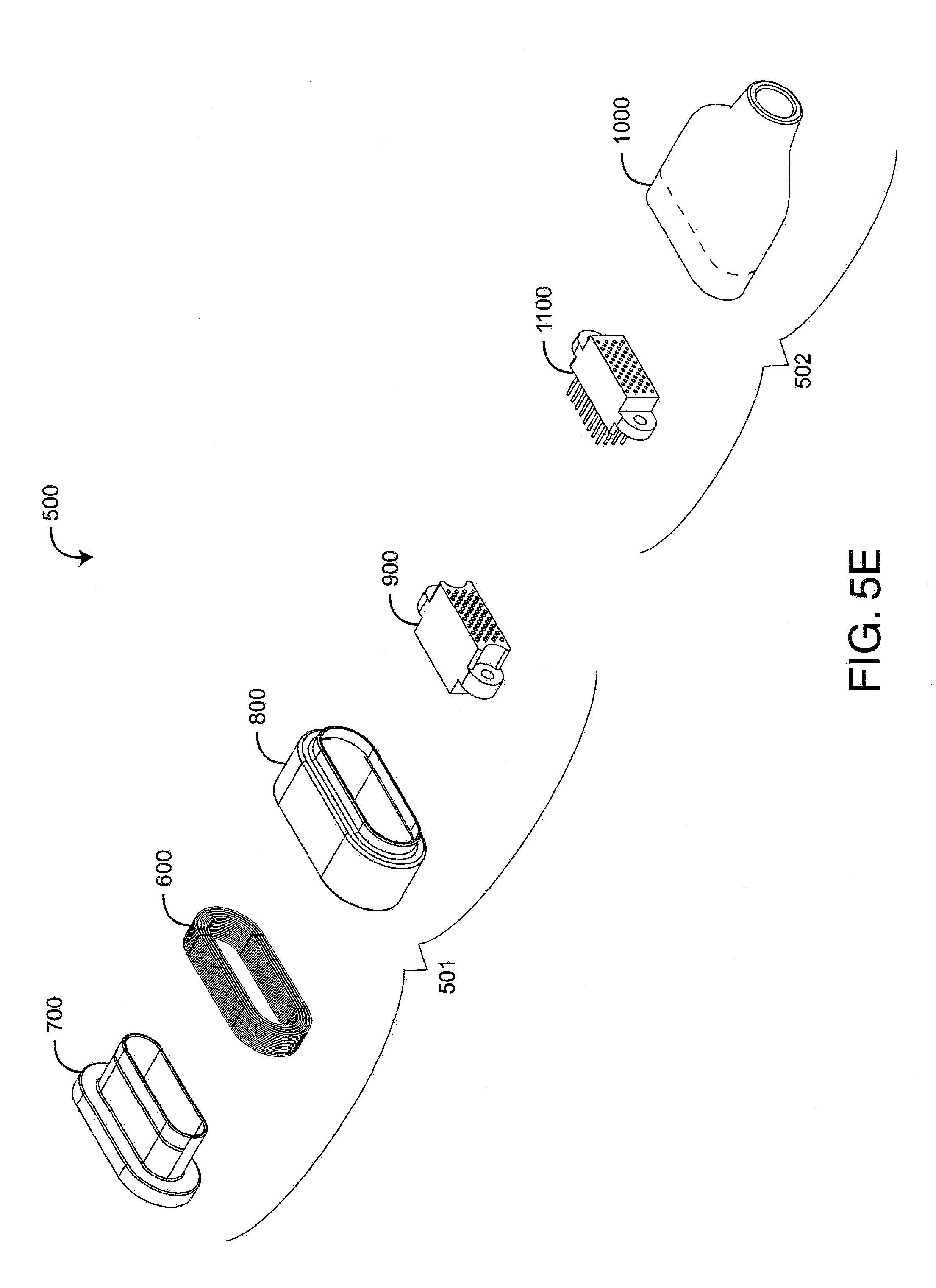
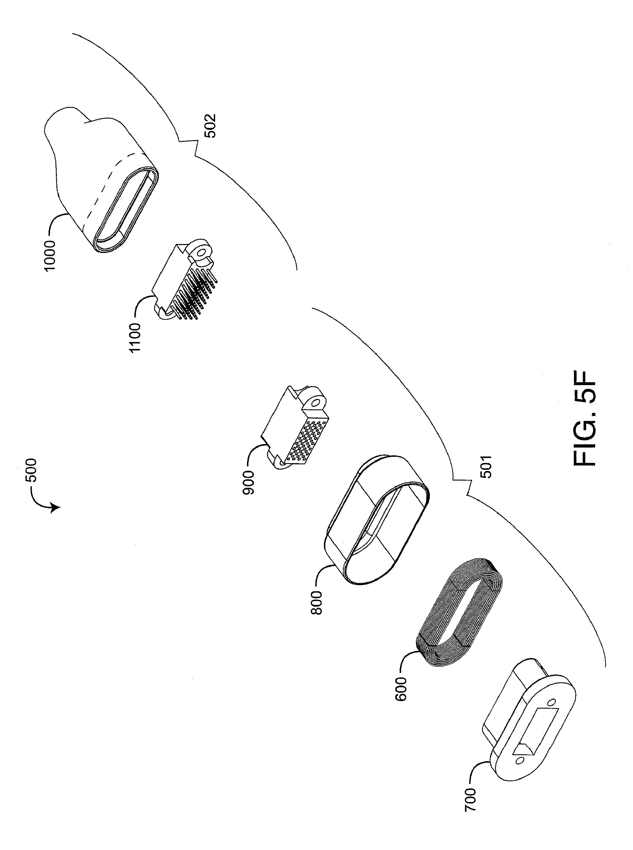
FIGS. 5A-F illustrate a magnetic connector embodiment 500 having a receptacle 501 and a plug 502. The receptacle 501 is mountable to a device, such as a physiological monitor. The plug 502 is attachable to a sensor cable or a patient cable. The receptacle 501 has a core 700, 800 (FIGS. 5E-F) that defines an elongated circular air gap 510. The plug 502 has a core 1000 (FIGS. 5E-F) that defines an elongated circular anchor 550, which inserts within the air gap 510. The receptacle core 700, 800 and corresponding coil 600 (FIGS. 5E-F) form an electromagnet that, when energized, generates a magnetic field within the air gap 510. Depending on the configuration, the electromagnetic field holds or releases the anchor 550 from the air gap 510 so as to lock or unlock the connection between the receptacle 501 and plug 502.
Also shown in FIGS. 5A-F, the receptacle 501 has a receptacle contact set 900 and the plug 502 has a plug contact set 1100. When the receptacle 501 and plug 502 are connected, the plug contact set 1100 inserts into the receptacle contact set 900, electrically coupling the receptacle 501 and socket 502. This electrical coupling provides an electrical path between cable conductors attached to the plug 502 at a cable end 560 (FIG. 5A) and wires attached to the receptacle 501 at a device end 530 (FIG. 5B).
As shown in FIGS. 5E-F, the receptacle 501 has a coil 600, an inner core 700, an outer core 800 and a contact set 900. The receptacle core 700, 800 forms a receptacle housing. In particular, the coil 600 is wound around the inner core 700 and enclosed by the outer core 800. The contact set 900 is mounted inside the inner core 700. The plug 502 has a core 1000 and a contact set 1100. The plug core 1000 forms a plug housing, and the contact set 1100 is mounted inside the plug core 1000.
FIGS. 6A-E are cross-sections of the receptacle core 700, 800 and plug core 1000. As shown in FIGS. 6A-C, the coil 600 is wound around the receptacle inner core 700 and enclosed by the outer core 800. Thus configured, the front edges of the receptacle core 700, 800 form an air gap 510. Likewise, the front edge of the plug core 1000 forms an anchor 550 that inserts (FIG. 6C) into the air gap 510. As shown in FIG. 6D, if DC current flows in the top-half of the coil in a direction into the page and in the bottom-half of the coil in a direction out of the page, then the magnetic field 603 produced by the coil has a north pole, N, at the left and a south pole, S, at the right (right-hand rule). As shown in FIG. 6E, the magnetic flux 604 in the receptacle core resulting from the magnetic field 603 is mostly confined within the walls of the receptacle core 700, 800, and results in a magnetic field in the air gap 510 as shown. As a result, the magnetic field in the air gap 510 has a north pole at the outer core portion and a south pole at the inner core portion. Thus, a "slice" of the receptacle core 700, 800 and corresponding air gap 510 are analogous to the core and air gap described with respect to FIGS. 4A-C, above. Likewise, a "slice" of the plug core 1000 and plug anchor 550 are analogous to the plug core and anchor described with respect to FIGS. 4A-C, above.
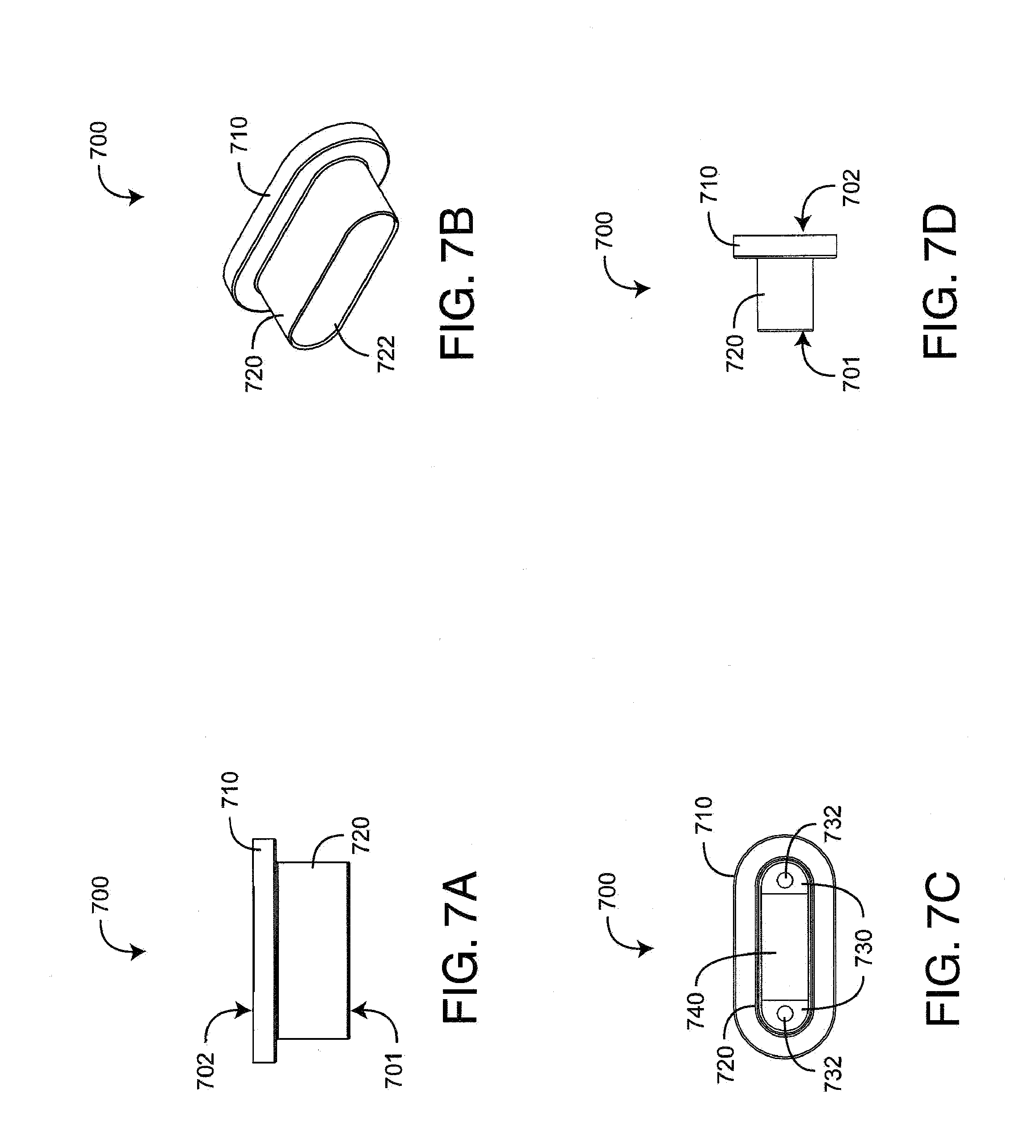
FIGS. 7-11 illustrate further details of the receptacle inner core 700, outer core 800, receptacle contact set 900, plug core 1000 and plug contact set 1100. As shown in FIGS. 7A-D, the receptacle inner core 700 mounts the receptacle contact set 900 (FIGS. 9A-D), supports the coil 600 (FIGS. 5E-F), and defines a portion of the receptacle core air gap 510 (FIG. 5A). The inner core 700 has a planar base 710 defining a back side 702 and a tubular coil support 720 extending from the base 710 and defining a front side 701. Both the base 710 and the coil support 720 have an elongated, circular cross-section. Inside the coil support 720 is a bracket 730 and corresponding bracket holes 732 for mounting the receptacle contact set 900 (FIGS. 9A-D). A wiring aperture 740 provides wiring access to the contact set 900 from the back side 702. An elongated circular edge 722 defines a portion of the air gap 510 (FIG. 5A) at the front side 701. In an embodiment (not shown), the base 710 provides chassis mounts for attaching the receptacle 501 (FIGS. 5A-B) to a monitor.
As shown in FIGS. 8A-D, the receptacle outer core 800 houses the coil, inner core and contact set and defines a portion of the receptacle core air gap 510 (FIG. 5A). The outer core 800 has a tubular housing 810 defining a back side 802 and a tubular edge 820 extending from the housing 810 and defining a front side 801. Both the housing 810 and the edge 820 have elongated circular cross-sections, with the edge 820 cross-section having a smaller circumference than the housing 810 cross-section. The edge 820 also defines a portion of the air gap 510 (FIG. 5A).
As shown in FIGS. 9A-D, the receptacle contact set 900 has a front side 901, a back side 902, a socket block 910 and corresponding contacts (not visible). The socket block 910 has a generally rectangular cross-sectioned body 910 and generally circular mounting ears 920 extending from the block sides. The ears have ear holes 922 that accept fasteners. The socket block 910 also has several rows of apertures 912 that extend from the front side 901 to the back side 902. Conductive contacts (not visible) are disposed within the apertures 912 and are configured to mate with corresponding plug pins 1130 (FIGS. 11A-D), described below. The receptacle contact set 900 mounts within the inner core 700 (FIGS. 7A-D) so that the mounting ears 920 rest on the core bracket 730 (FIGS. 7A-D). The contact set 900 is attached to the inner core 700 (FIGS. 7A-D) with fasteners disposed through the ear holes 922 and mounting holes 732 (FIGS. 7A-D).
As shown in FIGS. 10A-D, the plug core 1000 mounts the plug contact set 1100 (FIGS. 11A-D) and defines an anchor 550 (FIG. 5B) that releasably locks within the receptacle air gap 510 (FIG. 5A). The plug core 1000 has a tubular housing 1010 defining a back side 1002 and a tubular edge 1020 extending from the housing 1010 and defining a front side 1001. The edge 1020 has an elongated, circular cross-section. The housing 1010 has an elongated, circular cross-section near the front side 1001 and a circular cross-section near the back side that accommodates a cable (not shown). Inside the housing 1010 is a bracket 1030 and corresponding bracket holes 1032 for mounting the plug contact set 1100 (FIGS. 11A-D). A cable aperture 1040 provides cable entry for wiring access to the plug contact set 1100 (FIGS. 11A-D) via the back side 1002. The elongated circular edge 1020 defines the anchor 550 (FIG. 5B) at the front side 1001.
As shown in FIGS. 11A-D, the plug contact set 1100 has a front side 1101, a back side 1102, a pin block 1110 and corresponding pins 1130. The pin block 1110 has a generally rectangular cross-sectioned body having generally circular mounting ears 1120 extending from the block sides. The ears 1120 have ear holes 1122 that accept fasteners. The pin block 1110 also has several rows of apertures 1112 that extend from the front side 1101 to the back side 1102. Conductive pins 1130 are disposed within the apertures 1112 and are configured to mate with corresponding receptacle contacts, described above. The contact set 1100 mounts within the plug core 1000 (FIGS. 10A-D) so that the mounting ears 1120 rest on the core bracket 1030 (FIGS. 10A-D). The contact set 1100 is attached to the receptacle core 1000 (FIGS. 10A-D) with fasteners disposed through the ear holes 1122 and mounting holes 1032 (FIGS. 10A-D).
A magnetic connector has been disclosed in detail in connection with various embodiments. These embodiments are disclosed by way of examples only and are not to limit the scope of the claims that follow. One of ordinary skill in art will appreciate many variations and modifications.
* * * * *
D00000
D00001
D00002
D00003
D00004
D00005
D00006
D00007
D00008
D00009
D00010
D00011
D00012

D00013
D00014

D00015

D00016

D00017

XML
uspto.report is an independent third-party trademark research tool that is not affiliated, endorsed, or sponsored by the United States Patent and Trademark Office (USPTO) or any other governmental organization. The information provided by uspto.report is based on publicly available data at the time of writing and is intended for informational purposes only.
While we strive to provide accurate and up-to-date information, we do not guarantee the accuracy, completeness, reliability, or suitability of the information displayed on this site. The use of this site is at your own risk. Any reliance you place on such information is therefore strictly at your own risk.
All official trademark data, including owner information, should be verified by visiting the official USPTO website at www.uspto.gov. This site is not intended to replace professional legal advice and should not be used as a substitute for consulting with a legal professional who is knowledgeable about trademark law.