Device for measuring the filling level of a liquid
Fedgenhaeuer , et al. Fe
U.S. patent number 10,197,431 [Application Number 15/469,264] was granted by the patent office on 2019-02-05 for device for measuring the filling level of a liquid. This patent grant is currently assigned to HELLA KGAA HUECK & Co.. The grantee listed for this patent is Hella KGaA Hueck & Co.. Invention is credited to Silvio Fedgenhaeuer, Adam Sklorz, Sergej Tonewizki, Ingo Zoyke.

| United States Patent | 10,197,431 |
| Fedgenhaeuer , et al. | February 5, 2019 |
Device for measuring the filling level of a liquid
Abstract
A device for measuring the filling level of a liquid in a container with an ultrasound sensor and electronic components attached to the ultrasound sensor. A damping cup is arranged above the ultrasound sensor. The electronic components attached to the ultrasound sensor are separated from the liquid to be measured by a cover arranged above the electronic components. The cover has a recess in the vicinity of the ultrasound sensor, rests against the ultrasound sensor with the rim of the recess and is sealingly glued to the same.
| Inventors: | Fedgenhaeuer; Silvio (Bremen, DE), Tonewizki; Sergej (Diepholz, DE), Zoyke; Ingo (Stuhr-Moordeich, DE), Sklorz; Adam (Ganderkesee, DE) | ||||||||||
|---|---|---|---|---|---|---|---|---|---|---|---|
| Applicant: |
|
||||||||||
| Assignee: | HELLA KGAA HUECK & Co.
(Lippstadt, DE) |
||||||||||
| Family ID: | 59885235 | ||||||||||
| Appl. No.: | 15/469,264 | ||||||||||
| Filed: | March 24, 2017 |
Prior Publication Data
| Document Identifier | Publication Date | |
|---|---|---|
| US 20170284850 A1 | Oct 5, 2017 | |
Foreign Application Priority Data
| Mar 30, 2016 [DE] | 10 2016 003 657 | |||
| Current U.S. Class: | 1/1 |
| Current CPC Class: | F01M 11/12 (20130101); G01F 23/296 (20130101) |
| Current International Class: | G01F 23/296 (20060101); F01M 11/12 (20060101) |
References Cited [Referenced By]
U.S. Patent Documents
| 5184510 | February 1993 | Rossman |
| 5877997 | March 1999 | Fell |
| 6393922 | May 2002 | Winterer |
| 6629457 | October 2003 | Keller |
| 6993967 | February 2006 | Forgue |
| 7117738 | October 2006 | Miyagawa |
| 7370527 | May 2008 | Miyagawa |
| 7954384 | June 2011 | Koehler et al. |
| 7966136 | June 2011 | Reimer |
| 8191423 | June 2012 | Chiou et al. |
| 8276445 | October 2012 | Reiche |
| 8555716 | October 2013 | Niemann et al. |
| 8596139 | December 2013 | Mueller et al. |
| 8899109 | December 2014 | Niemann |
| 9006847 | April 2015 | Welter et al. |
| 9087504 | July 2015 | Mueller et al. |
| 9163974 | October 2015 | Kekalainen |
| 2009/0301187 | December 2009 | Beyer |
| 2009/0314575 | December 2009 | Reiche |
| 2010/0089169 | April 2010 | Koehler et al. |
| 2010/0262386 | October 2010 | Reimer |
| 2011/0005326 | January 2011 | Bentley |
| 2012/0174680 | July 2012 | Wade et al. |
| 2013/0221458 | August 2013 | Walter et al. |
| 2013/0270749 | October 2013 | Hachtmann et al. |
| 2014/0060177 | March 2014 | Kline |
| 2014/0352426 | December 2014 | Kuehnel et al. |
| 2015/0090018 | April 2015 | Niemann et al. |
| 2015/0377684 | December 2015 | Strackerjan et al. |
| 2016/0331284 | November 2016 | Pace |
| 201748957 | Feb 2011 | CN | |||
| 197 03 206 | Jul 1998 | DE | |||
| 199 42 378 | Mar 2001 | DE | |||
| 100 57 397 | May 2002 | DE | |||
| 10 2005 006 753 | Aug 2006 | DE | |||
| 10 2005 043 263 | Mar 2007 | DE | |||
| 10 2006 040 344 | Mar 2008 | DE | |||
| 10 2006 059 741 | Jul 2008 | DE | |||
| 10 2007 014 539 | Oct 2008 | DE | |||
| 10 2007 014 540 | Oct 2008 | DE | |||
| 20 2008 011 684 | Dec 2008 | DE | |||
| 10 2008 017 183 | Oct 2009 | DE | |||
| 10 2008 055 126 | Jul 2010 | DE | |||
| 10 2009 036 888 | Dec 2010 | DE | |||
| 10 2009 046 148 | May 2011 | DE | |||
| 10 2010 011 490 | Sep 2011 | DE | |||
| 10 2010 039 599 | Feb 2012 | DE | |||
| 11 2011 101 128 | Feb 2013 | DE | |||
| 10 2012 200 757 | Jul 2013 | DE | |||
| 10 2012 002 011 | Aug 2013 | DE | |||
| 10 2012 004 932 | Sep 2013 | DE | |||
| 102012004932 | Sep 2013 | DE | |||
| 10 2012 014 307 | Jan 2014 | DE | |||
| 10 2013 016 164 | Apr 2015 | DE | |||
| 10 2014 009 543 | Dec 2015 | DE | |||
| 10 2014 009 610 | Dec 2015 | DE | |||
| 2004-101353 | Apr 2004 | JP | |||
| 2004-294073 | Oct 2004 | JP | |||
| 2004-347378 | Dec 2004 | JP | |||
Other References
|
Epoxy resin adhesives for high temperature applications, DELO Company, Mar. 18, 2015 https://www.delo.de/fileadmin/user_upload/documents/de/brochures/Epoxidha- rz-Klebstoffe_fuer_Hochtemperatur-Anwendungen_DE.pdf (last retrieved on Mar. 29, 2017). cited by applicant . Habenicht, Gerd, "Plastics and other non-metallic materials" Bonding: Basics, technologies,applications, 2009, pp. 645-737. cited by applicant . Habenicht, Gerd, "Constructive design of metal bonding" Bonding: Basics, technologies, applications, 2009, pp. 529-537. cited by applicant. |
Primary Examiner: Rogers; David A
Attorney, Agent or Firm: Muncy, Geissler, Olds & Lowe, P.C.
Claims
The invention claimed is:
1. A device for measuring the filling level of a liquid in a container with an ultrasound sensor and electronic components attached to the ultrasound sensor, wherein a damping cup is arranged above the ultrasound sensor, wherein the electronic components attached to the ultrasound sensor are separated from the liquid to be measured by a cover arranged above the electronic components, the cover comprises a recess in the vicinity of the ultrasound sensor, and the cover with the rim of the recess rests against the ultrasound sensor and is sealingly glued to the same.
2. The device according to claim 1, wherein the top of the cover forms the bottom of the damping cup.
3. The device according to claim 1, wherein the top of the cover comprises holding structures for attaching the damping cup.
4. The device according to claim 1, wherein the cover is configured as a circular disc with a central recess.
5. The device according to claim 1, wherein the cover on its top comprises structures for forming an antechamber of the damping cup.
6. The device according to claim 1, wherein the cover on its bottom comprises downwardly extending steps perpendicular to the longitudinal plane of the cover, which are attached to its bottom.
7. The device according to claim 1, wherein liquid-free spaces are formed below the cover, which house the electronic components and electronic connections to the ultrasound sensor.
8. The device according to claim 1, wherein the cover on the rim of the recess comprises an approximately vertical section extending along the side of the ultrasound sensor, and a horizontal section extending across the ultrasound sensor roughly in horizontal direction.
9. The device according to claim 1, wherein the recess in the cover above the ultrasound sensor is formed as an opening and the cover rests against the ultrasound sensor by means of a ring-shaped adhesive connection.
10. An oil-lubricated engine, wherein the engine comprises a device according to claim 1.
11. A motor vehicle, wherein the motor vehicle comprises a device according to claim 1.
Description
BACKGROUND OF THE INVENTION
Field of the Invention
The invention relates to a device for measuring the filling level of a liquid in a container with an ultrasound sensor and electronic components attached to the ultrasound sensor, wherein a damping cup is arranged above the ultrasound sensor.
Brief Discussion of the Related Art
A device of this kind has been described for example in the DE 10 2014 009 610 A1. Such devices are used in particular for measuring the filling level of engine oil in an oil-lubricated engine, in particular in a motor vehicle. The filling level of the liquid is ascertained with the aid of ultrasound sensors. These emit sound waves, which are reflected at the interface between two media, here between air and oil, and which are received back by the ultrasound sensor. The recorded travel time of the sound waves is then used as a basis for ascertaining the filling level in the container holding the liquid. With a running engine, in particular in a motor vehicle, it is difficult, however, to ascertain the filling level of the oil, because the oil is very foamy and the sound waves are reflected at the gas bubbles in the oil. The values detected therefore vary widely across a wide area. In order to obtain measurements which can be evaluated, a unique interface is required between the gaseous medium such as air in this case, and the oil. In order to achieve this, the ultrasound sensors have so-called damping cups assigned to them. The damping cups usually comprise an ante-chamber. Within these damping cups, which surround the measuring section of the ultrasound sensor, the liquid to be measured is calmed and its connection to the container is limited to merely a small opening in the damping cup to the container. Due to the small opening in the damping cup to the container the amount of gas bubbles reaching the damping cup is reduced. The damping cups also serve to retard fluctuations generated e.g. by acceleration or by driving through bends and to take the mean of resulting fluctuations. In order to ensure maximum service life for the device, the ultrasound sensor with its electronic components is overmoulded in one known embodiment using a thermosetting plastic. In order to ensure that subsequent assembly processes can be carried out, the electrical connections are excluded from the overmoulding process.
SUMMARY OF THE INVENTION
The invention is based on the requirement to propose a device of the kind mentioned in the beginning, which is particularly robust and long-lasting. This requirement is met with a device having the characteristics of patent claim 1. Advantageous developments are proposed in the subclaims.
With a device for measuring the filling level of a liquid in a container comprising an ultrasound sensor and electronic components connected to the ultrasound sensor, wherein a damping cup is arranged above the ultrasound sensor, provision is made according to the invention for the electronic components connected to the ultrasound sensor to be separated from the liquid to be measured by a cover arranged above the electronic components, for the cover to comprise a recess in the vicinity of the ultrasound sensor and for the cover with the edge of the recess to rest against the ultrasound sensor and to be sealingly glued to the same. In this way a protected space is created around the ultrasound sensor and in particular below the same, which is sealed against the medium above it or against the liquid above it. The electronic components may be circuit elements and/or electrical lines and connections.
In the outer area the cover is also glued to a bottom arranged below it, so that cavities are created in which electronic components are arranged which are associated with the ultrasound sensor. As a result the electronic components and also their terminals and connections do not reside in the liquid to be measured, in particular not in the oil, and are therefore not attacked. Furthermore, with this embodiment there is no danger that any materials, which may be encasing the electronic components, may become detached due to vibrations or temperature fluctuations.
The cover is preferably configured as a circular disc with a central recess. This embodiment ensures that the cover is well adapted to the device. The central recess is provided for connection to the ultrasound sensor, enabling the ultrasound sensor to emit through this recess and allowing the ultrasound waves to reach the damping cup arranged above it.
With a preferred development of the invention the top of the cover forms the bottom of the damping cup. The damping cup can then be produced as a part which is open at the bottom and which is placed on top of the cover. On its top the cover is preferably equipped with holding structures for attaching the damping cup. In particular, the holding structures are formed as ring-shaped elevations, against which corresponding walls of the damping cup rest. In particular two ring-shaped elevations or annular edges surrounding each other are provided, between which an ante-chamber is formed within the damping cup. Furthermore the cover, on its top, conveniently comprises structures for forming an antechamber in the damping cup.
With another preferred development of the invention the cover, at its bottom, comprises downwardly extending structures perpendicular to the cover plane, which are attached, in particular glued, to the bottom. Gluing is in particular effected with a flange, which at the bottom can be inserted into the respective container, in which the filling level is measured. The whole device is preferably mounted onto a flange, which can be inserted, in particular inserted from below, into the container with the liquid to be measured. The device with the damping cup then extends preferably vertically upwards.
Below the cover liquid-free spaces are preferably formed, which house the electronic components and in which the electrical connection to the ultrasound sensor extends. In this case there is no need for overmoulding the electrical connections and the electronic components, since protection against the liquid to be measured is provided by the cover.
With another preferred development of the invention the cover at the central recess is provided with a roughly vertical section extending along the side of the ultrasound sensor, and a horizontal section extending to a certain extent across the ultrasound sensor. As a result the cover is, to some extent, guided around the upper corner of the ultrasound sensor, so that in this area a narrow area enclosing the upper rim of the ultrasound sensor is formed, in which an adhesive connection is made between the ultrasound sensor and the cover. Especially preferably the cover in this rim area, comprises a projection, which lies directly adjacent to the upper rim edge of the ultrasound sensor and in which the distance between the ultrasound sensor and the cover is minimal. This design results in a particularly effective adhesive connection.
With another preferred development of the invention the recess in the cover above the ultrasound sensor is configured as an opening. Here the cover rests against the ultrasound sensor and is continuously connected to the same by means of a ring-shaped adhesive connection. This ensures that the cover is altogether tight again, since the recess, which preferably is circular, is closed due to the ultrasound sensor arranged in the recess and the ring-shaped adhesive connection between the ultrasound sensor and the recess, specifically the rim of the recess.
A further aspect of the invention relates to an oil-lubricated engine wherein the engine comprises an above-described device for measuring the engine oil level. In other respects the invention relates to a motor vehicle with the above-mentioned device, in particular with the previously mentioned oil-lubricated motor.
BRIEF DESCRIPTION OF THE DRAWINGS
The invention will now be described in more detail by way of the embodiment depicted in the drawing. In detail, in the schematic representations:
FIG. 1 shows a schematic view of a device according to the invention;
FIG. 2 shows a sectional view of a damping cup of the device according to the invention;
FIG. 3 shows a sectional view through a lower area of the device according to the invention with ultrasound sensor and cover;
FIG. 4 shows a perspective view of FIG. 3;
FIG. 5 shows a perspective view in another section through the lower part of the device according to the invention;
FIG. 6 shows an enlarged view of the ultrasound sensor with the cover arranged above it and the ring-shaped adhesive connection.
DETAILED DESCRIPTION OF THE PREFERRED EMBODIMENTS
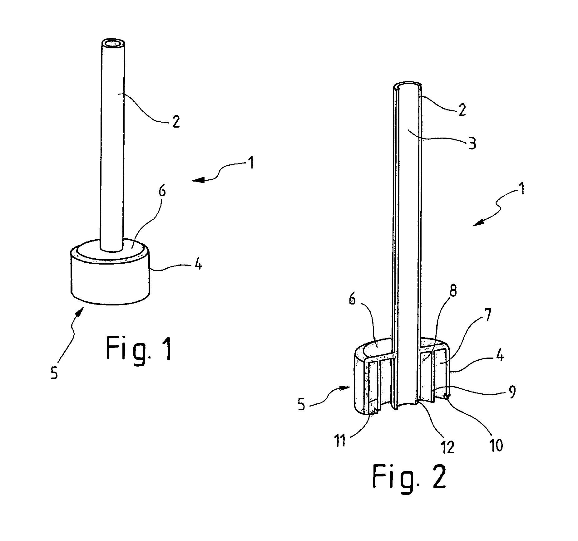
FIG. 1 shows a device 1, which in its upper area comprises a damping cup 2, inside which a measuring section extends. The ultrasound sensor not visible here emits ultrasound waves within this measuring section. In the lower area of the device 1 the damping cup comprises a pre-volume or antechamber 5. This antechamber 5 here essentially has an outer wall 4 and a lid 6.
FIG. 2 shows a cross-section through the upper part of the device 1 with the damping cup 2. The measuring section 3, at the bottom of which the ultrasound sensor not shown here is arranged, extends through the measuring section 2. Here the antechamber 5 consists of an inner ring 8 and an outer ring 7. These are formed by the outer wall 4 and an inner wall 9. In the view according to FIG. 2 the inflow 10 for the entry of the liquid from the container into the antechamber 5 can be recognised. This initially leads into the inner ring 7. The inflow 10 is essentially a breakthrough through the outer wall 4. This is located close to the bottom, in particular directly adjacent to the bottom of the device 1. The liquid can enter through an inflow 11 from the outer ring 7 into the inner ring 8. The inflow 11 is offset by 180.degree. from the inflow 10. The liquid is then able to get into the measuring section 3 from the inner ring 8 through an inflow 12. The inflow into the measuring section 3 is offset by 180.degree. from the inflow 11. Due to this arrangement of the inflows 10, 11 and 12 it is ensured that the liquid travels for a maximum possible distance in the antechamber 5, during which time it is calmed and outgassed thus resulting in a minimum of gas bubbles in the liquid, on which the ultrasound waves could reflect and interfere with the measuring result.
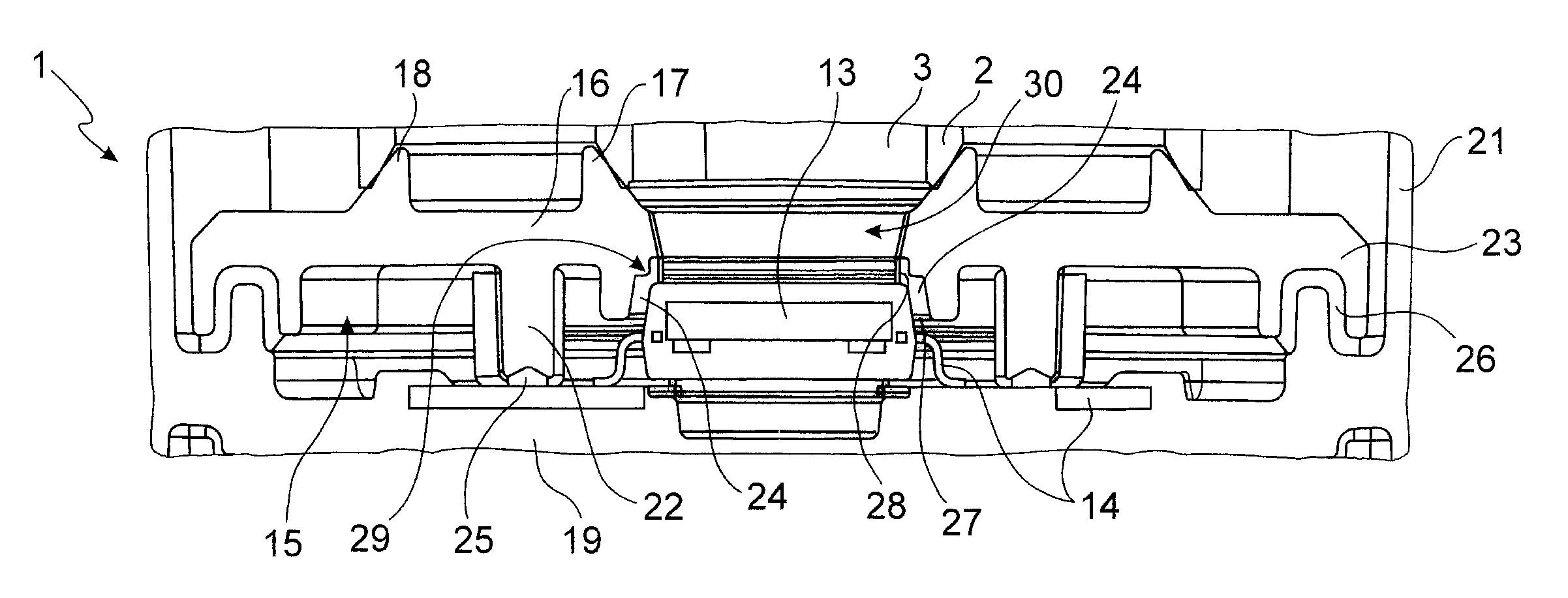
FIG. 3 shows a cross-section through the lower part of the device 1, in particular through the bottom area of the antechamber, which is not shown in FIGS. 1 and 2. In particular this figure shows the ultrasound sensor 13 with its electronic contacts 14, which are connected in downward direction. The electronic contacts 14 are part of the electronic components connected to the ultrasound sensor 13. The ultrasound sensor 13 is mounted onto a lower flange 19 and mounted centrally below the damping cup 2 and emits within the damping cup 2 into the vertically upward directed measuring section 3. Essential to the present invention is the cover 16 provided here, which comprises a central recess 30, which as regards size essentially corresponds to the diameter of the measuring section 3. The cover 16 with the recess 30, which could also be called a freed-up space, is configured and positioned such that the ultrasound sensor 13, the recess 30 and the measuring section 3 are arranged one above another and in alignment with each other. The cover 16 comprises ring-shaped structures on its top, which are used for connection to the antechamber 5. An inner annular edge 17 and an outer annular edge 18 are provided here, in particular. The inner annular edge 17 is joined here to the wall 2 of the damping cup. The outer annular edge 18 is joined to the inner wall 9 of the antechamber. Preferably the inner annular edge 17 is chamfered or sloped towards the inside and the outer annular edge 18 is chamfered or sloped towards the outside. Conversely the lower rim of the damping cup 2 is chamfered outwards, and the lower rim of the inner wall 9 is chamfered inwards. The chamfers correspond to each other, respectively. This leads to an automatic self-adjustment during assembly of the damping cup 2 with the antechamber 5 on the cover 16. Moreover the cover 16 comprises lower projections 22 and is connected here via an adhesive connection 26 to the flange 19. In the rim area of the cover 16 there is provided a connection area 23 of the cover 16 to the flange 19. Here an adhesive connection 26 is established between the cover 16 and the flange 19 using basically known construction and assembly technology. In the area of the recess 30 an adhesive connection 24 is provided between the cover 16 and the ultrasound sensor 13. This is provided in the shape of a ring around the upper outer edge of the ultrasound sensor 13. On the rim of the recess 16 a vertical part 27 and a horizontal part 28 of the cover can be recognised, which surround this upper rim of the ultrasound sensor 13. This produces an approximately uniform area for the adhesive connection 24 both horizontally and vertically. The vertical area is however distinctly longer than the horizontal area 28. Moreover the rim of the recess 30 shows a step 29 in the cover 16, which represents the minimum distance between the edge of the ultrasound sensor 13 and the cover 16. This allows a particularly good distribution of the adhesive compound in the area of the adhesive connection 24. For due to capillary forces substantially less adhesive spreads from the vertical part 27 onto the ultrasound sensor 13, thereby forming a particularly good adhesive connection.
FIG. 4 is a perspective sectional view onto the lower area of the device 1, which roughly corresponds to the area depicted in FIG. 3. Identical parts have been marked with identical reference symbols. Here the view upon the cover 16 is more from the top, so that, in particular the inner annular edge and the outer annular edge can be recognised. The inner annular edge 17 comprises a breakthrough 31, through which the liquid to be measured, in particular the oil, reaches the measuring section 3. Also the recess 30 or freed-up space and the adhesive connection 24 circumventing the recess 30 like a ring between the cover 16 and the ultrasound sensor 13 can be recognised here.
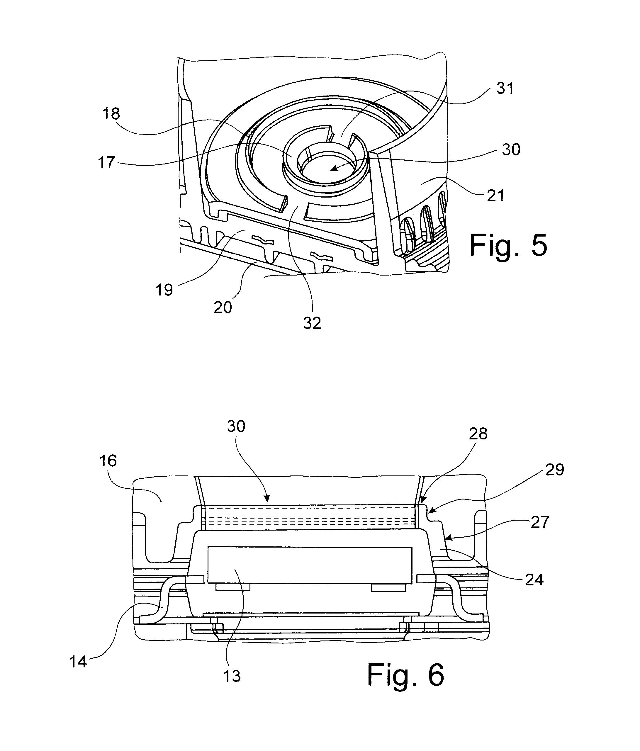
FIG. 5 shows a perspective view of the lower part of the device 1. This figure corresponds more or less to FIGS. 3 and 4, but it is viewed from a different perspective and using a different section. In particular the inner annular edge 17 with the breakthrough 31 and the outer annular edge 18 with the breakthrough 32 can be recognised. The breakthroughs 31 and 32 are offset by 180.degree. from one another, so that the liquid dwells for a maximum duration in the ante-chamber 5. Furthermore it shows the flange ring 21, which was merely indicated in FIGS. 3 and 4. The outer wall 4 of the antechamber 5 is placed onto this outer flange ring 21. To this end it is convenient if the outer wall 4, different from the view in FIG. 2, is shorter than the inner wall 9 and the wall of the damping cup 2, i.e. if it does not extend as far in downward direction.
FIG. 6 shows an enlarged cross-section in the area of the ultrasound sensor 13. The ultrasound sensor 13 can be recognised here with its contacts 14. The cover 16 extends at the rim and around the ultrasound sensor 13. The cover comprises the central recess 30 so that the ultrasound sensor 13 can emit in an upward direction and can receive from above. Between the cover 16 and the ultrasound sensor 13, in particular in the area of the upper annular edge or, in cross-section of the upper corner of the ultrasound sensor 13, the cover 16 and the ultrasound sensor 13 are in close proximity to each other, and this is also where the adhesive connection 24 is formed, with which the cover 16 is sealingly connected to the ultrasound sensor 13. The cover 16, to this end, comprises a vertical part 27 on the rim of the recess 30, which extends parallel to a part of the side wall of the ultrasound sensor 13. Furthermore the cover 16 comprises a horizontal part 28 shorter relative to this vertical part 27, wherein the horizontal part 28, within a short rim area, extends across the ultrasound sensor 13. In the transition area between this vertical part 27 and the horizontal part 28 a step 29 of the cover 16 is provided on the rim of the recess 30. This could also be called a C-groove. Here, due to a kind of projection in the cover, a projection comparable in shape and size to the corner of the ultrasound sensor 13 is formed, which lies opposite the upper corner of the ultrasound sensor 13 thus representing a minimum distance for forming an adhesive connection. In the area of this step 29 of the cover 16 the thickness of the adhesive connection 24 is approximately only half the thickness of the adhesive connection 24 at the widest point from the ultrasound sensor 13 to the horizontal part 28 of the cover 16.
All features mentioned in the above description and in the claims can be combined at random with the features of the independent claim. The disclosure of the invention is thus not limited to the described or claimed feature combinations, rather all feature combinations meaningful in terms of the invention are considered to have been disclosed.
* * * * *
References
D00000
D00001
D00002
D00003
XML
uspto.report is an independent third-party trademark research tool that is not affiliated, endorsed, or sponsored by the United States Patent and Trademark Office (USPTO) or any other governmental organization. The information provided by uspto.report is based on publicly available data at the time of writing and is intended for informational purposes only.
While we strive to provide accurate and up-to-date information, we do not guarantee the accuracy, completeness, reliability, or suitability of the information displayed on this site. The use of this site is at your own risk. Any reliance you place on such information is therefore strictly at your own risk.
All official trademark data, including owner information, should be verified by visiting the official USPTO website at www.uspto.gov. This site is not intended to replace professional legal advice and should not be used as a substitute for consulting with a legal professional who is knowledgeable about trademark law.