Electronic device with an interactive pressure sensitive multi-touch display
Vartanian , et al. Ja
U.S. patent number 10,191,652 [Application Number 15/694,930] was granted by the patent office on 2019-01-29 for electronic device with an interactive pressure sensitive multi-touch display. This patent grant is currently assigned to HJ Laboratories Licensing, LLC. The grantee listed for this patent is HJ LABORATORIES LICENSING, LLC. Invention is credited to Jaron Jurikson-Rhodes, Harry Vartanian.


| United States Patent | 10,191,652 |
| Vartanian , et al. | January 29, 2019 |
Electronic device with an interactive pressure sensitive multi-touch display
Abstract
An information view may be displayed on a multi-touch display based on a touch input and based on detected pressure and a depth from a three dimensional touch input on a displayed image on the multi-touch display.
| Inventors: | Vartanian; Harry (Bryn Mawr, PA), Jurikson-Rhodes; Jaron (Philadelphia, PA) | ||||||||||
|---|---|---|---|---|---|---|---|---|---|---|---|
| Applicant: |
|
||||||||||
| Assignee: | HJ Laboratories Licensing, LLC
(Bryn Mawr, PA) |
||||||||||
| Family ID: | 42737109 | ||||||||||
| Appl. No.: | 15/694,930 | ||||||||||
| Filed: | September 4, 2017 |
Prior Publication Data
| Document Identifier | Publication Date | |
|---|---|---|
| US 20170364256 A1 | Dec 21, 2017 | |
Related U.S. Patent Documents
| Application Number | Filing Date | Patent Number | Issue Date | ||
|---|---|---|---|---|---|
| 15365225 | Nov 30, 2016 | 9772772 | |||
| 15239264 | Jan 17, 2017 | 9547368 | |||
| 15145766 | Sep 20, 2016 | 9448632 | |||
| 14485246 | May 10, 2016 | 9335824 | |||
| 13291375 | Oct 21, 2014 | 8866766 | |||
| 12406273 | Apr 1, 2014 | 8686951 | |||
| Current U.S. Class: | 1/1 |
| Current CPC Class: | G06F 3/0485 (20130101); G09G 3/3208 (20130101); G06F 3/0416 (20130101); G06F 3/04845 (20130101); G06F 3/016 (20130101); G06F 3/04886 (20130101); G06F 3/0488 (20130101); G06F 3/0412 (20130101); G06F 3/04883 (20130101); G06F 3/0414 (20130101); H01H 13/85 (20130101); H03K 17/9643 (20130101); G06F 3/0346 (20130101); G06F 3/0486 (20130101); G06F 3/041 (20130101); G06F 2203/04806 (20130101); H01H 2217/006 (20130101); G06F 2203/04809 (20130101); G06F 2203/04102 (20130101); G06F 2203/04104 (20130101); H01H 2215/052 (20130101); H01H 2215/05 (20130101); H01H 2217/038 (20130101); G06F 2203/04105 (20130101) |
| Current International Class: | G06F 3/0488 (20130101); H03K 17/96 (20060101); H01H 13/85 (20060101); G06F 3/0486 (20130101); G09G 3/3208 (20160101); G06F 3/01 (20060101); G06F 3/0346 (20130101); G06F 3/0484 (20130101); G06F 3/041 (20060101); G06F 3/0485 (20130101) |
References Cited [Referenced By]
U.S. Patent Documents
| 4871992 | October 1989 | Petersen |
| 5327457 | July 1994 | Leopold |
| 5402490 | March 1995 | Mihm, Jr. |
| 5412189 | May 1995 | Cragun |
| 5463657 | October 1995 | Rice |
| 5490087 | February 1996 | Redden et al. |
| 5504938 | April 1996 | Redden |
| 5602901 | February 1997 | Redden et al. |
| 5673256 | September 1997 | Maine |
| 5712870 | January 1998 | Petrick |
| 5717434 | February 1998 | Toda |
| 5724659 | March 1998 | Daniel et al. |
| 5752162 | May 1998 | Sawyer et al. |
| 5825308 | October 1998 | Rosenberg |
| 5867144 | February 1999 | Wyard |
| 5867789 | February 1999 | Olds et al. |
| 5888161 | March 1999 | McCarrick et al. |
| 5892902 | April 1999 | Clark |
| 6004049 | December 1999 | Knox |
| 6037882 | March 2000 | Levy |
| 6075967 | June 2000 | Naimark et al. |
| 6104922 | August 2000 | Baumann |
| 6117296 | September 2000 | Thomson |
| 6131032 | October 2000 | Patel |
| 6140913 | October 2000 | Okada et al. |
| 6185536 | February 2001 | Haber et al. |
| 6204896 | March 2001 | Matsuhira et al. |
| 6243078 | June 2001 | Rosenberg |
| 6255938 | July 2001 | Bornschein |
| 6266690 | July 2001 | Shankarappa et al. |
| 6313825 | November 2001 | Gilbert |
| 6359978 | March 2002 | Brady |
| 6434702 | August 2002 | Maddalozzo, Jr. et al. |
| 6441828 | August 2002 | Oba et al. |
| 6456245 | September 2002 | Crawford |
| 6462840 | October 2002 | Kravtsov |
| 6487657 | November 2002 | Brockmann |
| 6492979 | December 2002 | Kent et al. |
| 6535201 | March 2003 | Cooper et al. |
| 6559620 | May 2003 | Zhou et al. |
| 6563487 | May 2003 | Martin et al. |
| 6571102 | May 2003 | Hogberg et al. |
| 6597347 | July 2003 | Yasutake |
| 6628511 | September 2003 | Engstrom |
| 6646540 | November 2003 | Lussey |
| 6680731 | January 2004 | Gerpheide et al. |
| 6700553 | March 2004 | Becker et al. |
| 6703550 | March 2004 | Chu |
| 6744178 | June 2004 | Muramatsu et al. |
| 6782102 | August 2004 | Blanchard et al. |
| 6787238 | September 2004 | Zhang et al. |
| 6823787 | November 2004 | Saueressig |
| 6842428 | January 2005 | Chen et al. |
| 6842607 | January 2005 | Godfrey et al. |
| 6852416 | February 2005 | Zhang et al. |
| 6859569 | February 2005 | Ishibashi et al. |
| 6859572 | February 2005 | Ishibashi |
| 6881063 | April 2005 | Yang |
| 6882086 | April 2005 | Kornbluh et al. |
| 6888161 | May 2005 | Shih |
| 6925495 | August 2005 | Hegde et al. |
| 6984208 | January 2006 | Zheng |
| 6988247 | January 2006 | Janevski |
| 7027311 | April 2006 | Vanderelli et al. |
| 7042711 | May 2006 | Tanaka et al. |
| 7042997 | May 2006 | Jones |
| 7050835 | May 2006 | Hack et al. |
| 7054145 | May 2006 | Tanaka et al. |
| 7077015 | July 2006 | Hayward et al. |
| 7084859 | August 2006 | Pryor |
| 7102621 | September 2006 | Roberts |
| 7109967 | September 2006 | Hioki et al. |
| 7113177 | September 2006 | Franzen |
| 7138985 | November 2006 | Nakajima |
| 7151527 | December 2006 | Culver |
| 7184032 | February 2007 | Stohrer et al. |
| 7186356 | March 2007 | Lussey et al. |
| 7190416 | March 2007 | Paukshto et al. |
| 7193350 | March 2007 | Blackburn et al. |
| 7253807 | August 2007 | Nakajima |
| 7269153 | September 2007 | Schultz et al. |
| 7274652 | September 2007 | Webster et al. |
| 7301435 | November 2007 | Lussey et al. |
| 7317872 | January 2008 | Posa et al. |
| 7339572 | March 2008 | Schena |
| 7352356 | April 2008 | Roberts et al. |
| 7368307 | May 2008 | Cok |
| 7377133 | May 2008 | Sandbach et al. |
| 7382357 | June 2008 | Panotopoulos et al. |
| 7400640 | July 2008 | Fischer et al. |
| 7406057 | July 2008 | Isomaki et al. |
| 7408872 | August 2008 | Palin et al. |
| 7436318 | October 2008 | Affolter et al. |
| 7444157 | October 2008 | Hovers et al. |
| 7455304 | November 2008 | Porter |
| 7461353 | December 2008 | Rohrabaugh et al. |
| 7495348 | February 2009 | Mund et al. |
| 7500952 | March 2009 | Chiang et al. |
| 7511702 | March 2009 | Hotelling |
| 7522153 | April 2009 | Ohtsuka |
| 7548232 | June 2009 | Shahoian et al. |
| 7554045 | June 2009 | Sandbach et al. |
| 7554051 | June 2009 | Crispin |
| 7561141 | July 2009 | Shahoian et al. |
| 7567243 | July 2009 | Hayward |
| 7592999 | September 2009 | Rosenberg et al. |
| 7593067 | September 2009 | Taguchi |
| 7656394 | February 2010 | Westerman et al. |
| 7731670 | June 2010 | Aguirre-Ollinger et al. |
| 7756297 | July 2010 | Pryor |
| 7787646 | August 2010 | Pelrine et al. |
| 7828733 | November 2010 | Zhang et al. |
| 7841944 | November 2010 | Wells |
| 7843449 | November 2010 | Krah |
| 7844915 | November 2010 | Platzer et al. |
| 7893928 | February 2011 | Im |
| 7953462 | May 2011 | Harry |
| 7982588 | July 2011 | Makinen et al. |
| 8068101 | November 2011 | Goertz |
| 8095879 | January 2012 | Goertz |
| 8125463 | February 2012 | Hotelling et al. |
| 8136402 | March 2012 | Cato |
| 8144271 | March 2012 | Han |
| 8169416 | May 2012 | Han |
| 8209628 | June 2012 | Davidson |
| 8232973 | July 2012 | Kocienda et al. |
| 8255323 | August 2012 | Casey et al. |
| 8406816 | March 2013 | Marui et al. |
| 8416213 | April 2013 | Shen |
| 8433138 | April 2013 | Wang et al. |
| 8441467 | May 2013 | Han |
| 8477116 | July 2013 | Ningrat |
| 8547339 | October 2013 | Ciesla |
| 8558803 | October 2013 | Park et al. |
| 8593409 | November 2013 | Heubel |
| 8619051 | December 2013 | Lacroix et al. |
| 8674948 | March 2014 | Han et al. |
| 8686952 | April 2014 | Burrough et al. |
| 8760413 | June 2014 | Peterson et al. |
| 8773356 | July 2014 | Martin et al. |
| 8825113 | September 2014 | Kim et al. |
| 8856692 | October 2014 | Kim |
| 9250734 | February 2016 | Hotelling et al. |
| 9310984 | April 2016 | Kim |
| 9697556 | July 2017 | Mazed et al. |
| 9772772 | September 2017 | Vartanian |
| 2002/0030699 | March 2002 | Van Ee |
| 2002/0050983 | May 2002 | Liu et al. |
| 2002/0158836 | October 2002 | Ishmael |
| 2003/0038776 | February 2003 | Rosenberg et al. |
| 2003/0048260 | March 2003 | Matusis |
| 2003/0058265 | March 2003 | Robinson et al. |
| 2004/0056877 | March 2004 | Nakajima |
| 2004/0100448 | May 2004 | Moshrefzadeh |
| 2004/0199232 | October 2004 | Wallace et al. |
| 2005/0012723 | January 2005 | Pallakoff |
| 2005/0088417 | April 2005 | Mulligan |
| 2005/0157893 | July 2005 | Pelrine et al. |
| 2006/0007078 | January 2006 | Lee et al. |
| 2006/0022955 | February 2006 | Kennedy |
| 2006/0026521 | February 2006 | Hotelling |
| 2006/0092344 | May 2006 | Ura et al. |
| 2006/0096392 | May 2006 | Inkster et al. |
| 2006/0103634 | May 2006 | Kim et al. |
| 2006/0186802 | August 2006 | Cok et al. |
| 2006/0197752 | September 2006 | Hurst et al. |
| 2006/0197753 | September 2006 | Hotelling |
| 2006/0209083 | September 2006 | Rosenberg |
| 2006/0221016 | October 2006 | Nakamura |
| 2007/0020589 | January 2007 | Smith et al. |
| 2007/0078345 | April 2007 | Mo et al. |
| 2007/0085828 | April 2007 | Schroeder et al. |
| 2007/0085838 | April 2007 | Ricks et al. |
| 2007/0091070 | April 2007 | Larsen et al. |
| 2007/0106949 | May 2007 | Narita et al. |
| 2007/0109276 | May 2007 | Kim et al. |
| 2007/0139391 | June 2007 | Bischoff |
| 2007/0152962 | July 2007 | Kim et al. |
| 2007/0152974 | July 2007 | Kim et al. |
| 2007/0182708 | August 2007 | Poupyrev et al. |
| 2007/0193267 | August 2007 | He |
| 2007/0200496 | August 2007 | Cok et al. |
| 2007/0220427 | September 2007 | Briancon et al. |
| 2007/0247422 | October 2007 | Vertegaal et al. |
| 2007/0247429 | October 2007 | Westerman |
| 2007/0257891 | November 2007 | Esenther et al. |
| 2008/0005703 | January 2008 | Radivojevic et al. |
| 2008/0042981 | February 2008 | Katz |
| 2008/0062088 | March 2008 | Chang et al. |
| 2008/0062148 | March 2008 | Hotelling et al. |
| 2008/0100907 | May 2008 | Lipovetskaya et al. |
| 2008/0122589 | May 2008 | Ivanov |
| 2008/0129705 | June 2008 | Kim et al. |
| 2008/0136786 | June 2008 | Lanfermann |
| 2008/0150911 | June 2008 | Harrison |
| 2008/0180399 | July 2008 | Cheng |
| 2008/0180406 | July 2008 | Han et al. |
| 2008/0211353 | September 2008 | Seeley et al. |
| 2008/0216001 | September 2008 | Ording |
| 2008/0224948 | September 2008 | Alberth |
| 2008/0231610 | September 2008 | Hotelling et al. |
| 2008/0246726 | October 2008 | Gettemy |
| 2008/0259236 | October 2008 | Kwon et al. |
| 2008/0291521 | November 2008 | Kim et al. |
| 2008/0291525 | November 2008 | Kim et al. |
| 2008/0303795 | December 2008 | Lowles et al. |
| 2009/0002140 | January 2009 | Higa |
| 2009/0002205 | January 2009 | Klinghult et al. |
| 2009/0002328 | January 2009 | Ullrich et al. |
| 2009/0015560 | January 2009 | Robinson et al. |
| 2009/0043195 | February 2009 | Poland |
| 2009/0043205 | February 2009 | Pelissier et al. |
| 2009/0051662 | February 2009 | Klein et al. |
| 2009/0058828 | March 2009 | Jiang |
| 2009/0061948 | March 2009 | Lee et al. |
| 2009/0070711 | March 2009 | Kwak |
| 2009/0102805 | April 2009 | Meijer et al. |
| 2009/0153368 | June 2009 | Hur et al. |
| 2009/0160813 | June 2009 | Takashima et al. |
| 2009/0167704 | July 2009 | Terlizzi et al. |
| 2009/0174671 | July 2009 | Tachi et al. |
| 2009/0174687 | July 2009 | Ciesla et al. |
| 2009/0181724 | July 2009 | Pettersson |
| 2009/0182501 | July 2009 | Fyke et al. |
| 2009/0184936 | July 2009 | Algreatly |
| 2009/0189748 | July 2009 | Bergere |
| 2009/0189873 | July 2009 | Peterson et al. |
| 2009/0189878 | July 2009 | Goertz et al. |
| 2009/0195512 | August 2009 | Pettersson |
| 2009/0198132 | August 2009 | Pelissier et al. |
| 2009/0199392 | August 2009 | Singh et al. |
| 2009/0213066 | August 2009 | Hardacker et al. |
| 2009/0231271 | September 2009 | Heubel et al. |
| 2009/0237364 | September 2009 | Bloomcamp et al. |
| 2009/0237373 | September 2009 | Hansson |
| 2009/0256807 | October 2009 | Nurmi |
| 2009/0256857 | October 2009 | Davidson et al. |
| 2009/0262078 | October 2009 | Pizzi |
| 2009/0284480 | November 2009 | Seacat |
| 2009/0286211 | November 2009 | Eisenhardt et al. |
| 2009/0295760 | December 2009 | Linge et al. |
| 2009/0303022 | December 2009 | Griffin et al. |
| 2009/0309851 | December 2009 | Bernstein |
| 2009/0315830 | December 2009 | Westerman |
| 2009/0315851 | December 2009 | Hotelling et al. |
| 2009/0322687 | December 2009 | Duncan et al. |
| 2010/0001973 | January 2010 | Hotelling et al. |
| 2010/0007511 | January 2010 | Ina et al. |
| 2010/0007613 | January 2010 | Costa |
| 2010/0013777 | January 2010 | Baudisch et al. |
| 2010/0026640 | February 2010 | Kim et al. |
| 2010/0026656 | February 2010 | Hotelling et al. |
| 2010/0085169 | April 2010 | Poupyrev et al. |
| 2010/0103115 | April 2010 | Hainzl |
| 2010/0115448 | May 2010 | Lysytskyy et al. |
| 2010/0128002 | May 2010 | Stacy et al. |
| 2010/0151426 | June 2010 | Tachi et al. |
| 2010/0156803 | June 2010 | Wu |
| 2010/0156818 | June 2010 | Burrough et al. |
| 2010/0160786 | June 2010 | Nordgren et al. |
| 2010/0162109 | June 2010 | Chatterjee |
| 2010/0171715 | July 2010 | Peterson et al. |
| 2010/0177050 | July 2010 | Heubel et al. |
| 2010/0177055 | July 2010 | Ookawara et al. |
| 2010/0182245 | July 2010 | Edwards et al. |
| 2010/0207775 | August 2010 | Lenneman et al. |
| 2010/0207902 | August 2010 | Juan et al. |
| 2010/0225456 | September 2010 | Eldering |
| 2010/0225734 | September 2010 | Weller et al. |
| 2010/0231540 | September 2010 | Cruz-Hernandez et al. |
| 2010/0231541 | September 2010 | Cruz-Hernandez et al. |
| 2010/0234077 | September 2010 | Yoo et al. |
| 2010/0238114 | September 2010 | Vartanian et al. |
| 2010/0238116 | September 2010 | Shin |
| 2010/0238117 | September 2010 | Fitzgibbon et al. |
| 2010/0257491 | October 2010 | Geurts et al. |
| 2010/0259633 | October 2010 | Kii |
| 2010/0283731 | November 2010 | Grant et al. |
| 2010/0295820 | November 2010 | Kikin-Gil |
| 2010/0298713 | November 2010 | Robinson |
| 2011/0043485 | February 2011 | Goertz |
| 2011/0107958 | May 2011 | Pance et al. |
| 2011/0109588 | May 2011 | Makinen et al. |
| 2011/0175813 | July 2011 | Sarwar et al. |
| 2011/0199342 | August 2011 | Vartanian et al. |
| 2012/0113018 | May 2012 | Yan |
| 2013/0159941 | June 2013 | Langlois et al. |
| 676781 | Jan 1999 | EP | |||
| 2382291 | May 2003 | GB | |||
| 2001117721 | Apr 2001 | JP | |||
| 2003029898 | Jan 2003 | JP | |||
| 3739927 | Jan 2006 | JP | |||
| 3913496 | May 2007 | JP | |||
| 20040076415 | Sep 2004 | KR | |||
| 20080023901 | Mar 2008 | KR | |||
| 594183 | Jun 2004 | TW | |||
| 9917929 | Apr 1999 | WO | |||
| 03003185 | Jan 2003 | WO | |||
| 2007012899 | Feb 2007 | WO | |||
| 07069835 | Jun 2007 | WO | |||
| 2007114699 | Oct 2007 | WO | |||
| 2008037275 | Apr 2008 | WO | |||
| 2010054014 | May 2010 | WO | |||
| 2010085575 | Jul 2010 | WO | |||
| 10086866 | Aug 2010 | WO | |||
Other References
|
"Apple Introduces the Incredible Shape Shifting Device Interface," Patently Apple, Jun. 24, 2010. cited by applicant . "Artificial muscles get a makeover," accessed at http://www.msnbc.msn.com/id/11858650/, Mar. 16, 2006. cited by applicant . "Artificial Muscles," Nov. 23, 2006. cited by applicant . "Electric Flex," (2001) Date Unknown, accessed at http://www.Spectrum.ieee.org/print/1579. cited by applicant . "Fundamental research on polymer material as artificial muscle," Apr. 1, 2008 (Abstract). cited by applicant . "Materials and Technologies for Artificial Muscle: A Review for the Mechatronic Muscle Project," Date Unknown. cited by applicant . "New Class of Composite Organic Material Could Put the Muscle in Artificial Body Parts," Sep. 19, 2002. cited by applicant . "New Polymers and Nanotubes Add Muscle to Prosthetic Limbs," Aug. 1999. cited by applicant . "PulseTouch.TM. technology," Date Unknown. cited by applicant . "Refreshable Braille Display," Date Unknown. cited by applicant . "Small jolts move artificial muscle," Oct. 2-9, 2002. cited by applicant . "Sony's Flexible OLED," accessed at http://www.youtube.com/watch?v=NcAm3KihFho. cited by applicant . "Team post Braille ebook concept," bit-tech.net, Apr. 21, 2009. cited by applicant . "Two Dimensional Radiation Pressure Tactile Display," Aug. 8-10, 2005. cited by applicant . "Unusual material that contracts when heated is giving up its secrets to physicists," Nov. 18, 2004. cited by applicant . "W&M Professor Heads Facility Studying Piezoelectric Material," Jul. 6, 2001. cited by applicant . 3DTV Experience--Philips WOWvx 3D Display; Date Unknown. cited by applicant . Amemiya et al., "Portable Haptic Feedback Display for Virtual Reality," 1999, Abstract Only. cited by applicant . "Artificial Muscle Material with Fast Electroactuation under Neutral pH Conditions," Abstract Only, May 21, 2004. cited by applicant . Bau, et al., "BubbleWrap: A Textile-Based Electromagnetic Haptic Display," CHI 2009, Apr. 4-9, 2009, Boston, Massachusetts, USA. cited by applicant . Chouvardas et al., "Tactile display applications: a state of the art survey," 2005. cited by applicant . Chouvardas et al., "Tactile Displays: a short overview and recent developments," 2007. cited by applicant . Davies, C., "NHK develop precise haptic-feedback touchscreen," Slashgear, May 16, 2008. cited by applicant . Harrison et al., "Texture Displays: A Passive Approach to Tactile Presentation," Apr. 9, 2009. cited by applicant . Howe, R., "The Haptic Community Web Site--Haptic Research: Tactile Display," Apr. 3, 2002. cited by applicant . Vijayan, J., "User interfaces: The next generation," Aug. 9, 2004. cited by applicant . Khoudja et al., "Tactile interfaces: a state-of-the-art survey," CEA List SRSI, 2004, France. cited by applicant . Kim et al., "Small and Lightweight Tactile Display (SaLT) and its Application," Third Joint Eurohaptics Conference and Symposium on Haptic Interfaces for Virtual Environment and Teleoperator Systems, Mar. 18-20, 2009, pp. 69-74, Salt Lake City, UT, USA. cited by applicant . "NC State Scientists Engineer `Pumped-Up,` Materials," accessed Sep. 6, 2007. cited by applicant . Ooshita et al., "Tokyo University Realizes Light-weight, Flexible Braille Display Sheet Using Organic Transistors," Nov. 25, 2005. cited by applicant . "Patent: TouchEngine: A Tactile Display for Handheld Devices". cited by applicant . Poupyrev et al., "Haptic feedback for pen computing: directions and strategies," 2004, Abstract Only. cited by applicant . Sharifi et al., "Design and implementation of a graphic-haptic display system," Nov. 24, 2006. cited by applicant . Shinoda et al. "A Tactile Feeling Display Based on Selective Stimulation of Skin Receptors," Proceedings of the IEEE Virtual Reality Annual International Symposium, Mar. 1998, pp. 36-42, Atlanta, Georgia, USA. cited by applicant . Shinoda et al., "Two Dimensional Stress Reproduction Using Ultrasound Tactile Display," SICE-ICASE International Joint Conference 2006, Oct. 18-21, 2006, pp. 4818-4821, Bexco, Busan, Korea. cited by applicant . Shinoda et al., "Two-dimensional Scanning Tactile Display using Ultrasound Radiation Pressure," 14th Symposium on Haptic Interfaces for Virtual Environment and Teleoperator Systems, pp. 57-61, Mar. 25-26, 2006. cited by applicant . Shinohara et al., "A blind person's interactions with technology," Communications of the ACM, vol. 52, No. 8, pp. 58-66, Aug. 2009. cited by applicant . Stone, R., "Haptic Feedback: A Potted History, From Telepresence to Virtual Reality," 2007, UK. cited by applicant . Hasser, "Tactile Feedback for a Force-Reflecting Haptic Display," Dec. 1995, Abstract Only. cited by applicant . Gizmodo, "Braille E-Reader Concept Raises Dots with E-Ink," Apr. 20, 2009. cited by applicant . Response to Non-final Office Action from U.S. Appl. No. 12/406,273 dated Sep. 21, 2011. cited by applicant . "TPaD: Tactile Pattern Display (2007)," Mar. 27, 2007. cited by applicant . Wright, J., "Next for Touchscreens: Temporary Pop-Up Buttons?," Popular Mechanics, Aug. 2009. cited by applicant . Zyga, L., "Researchers Design Band-Aid-Size Tactile Display," PHYSORG.com, Jun. 6, 2006. cited by applicant . Notice of Allowance from U.S. Appl. No. 13/291,375 dated Oct. 4, 2013. cited by applicant . Non-final Office Action from U.S. Appl. No. 12/406,273 dated Jun. 22, 2011. cited by applicant . Response to Office Action from U.S. Appl. No. 12/406,273 dated Jan. 16, 2012. cited by applicant . Final Office Action from U.S. Appl. No. 12/406,273 dated Apr. 2, 2012. cited by applicant . Response to Final Office Action from U.S. Appl. No. 12/406,273 dated Jul. 2, 2012. cited by applicant . Notice of Allowance from U.S. Appl. No. 12/406,273 dated Aug. 28, 2013. cited by applicant . Iwamoto et al., "A Tactile Display using Ultrasound Linear Phased Array", International Conference on Artificial Reality and Telexistence, 2004, Seoul, Korea. cited by applicant . Hoshi et al., "Adding Tactile Reaction to Hologram", The 18th IEEE International Symposium on Robot and Human Interactive Communication, Sep. 27-Oct. 2, 2009, pp. 7-11, Toyama, Japan. cited by applicant . Iwamoto et al., "Finger Ring Device for Tactile Sensing and Human Machine Interface", SICE Annual Conference 2007, Kagawa University, Sep. 17-20, 2007, pp. 2132-2136, Japan. cited by applicant . Shinoda et al., "Touchable Holography" http://www.youtube.com/watch?v=Y-P1zZAcPuw, Posted Jul. 16, 2009, University of Tokyo. cited by applicant . Iwamoto et al., "Airborne Ultrasound Tactile Display," SIGGRAPH 2008 New Tech Demos, Aug. 2008. cited by applicant . Notice of Allowance from U.S. Appl. No. 15/239,264 dated Dec. 6, 2016. cited by applicant . Hodges et al., "ThinSight: Versatile Multi-touch Sensing for Thin Form-factor Displays," Proceedings of the 20th annual ACM symposium on User interface software and technology, Oct. 1, 2007, pp. 259-268, Newport, Rhode Island, USA. cited by applicant . Notice of Allowance from U.S. Appl. No. 12/406,273 dated Dec. 13, 2013. cited by applicant . Applicant-Initiated Interview Summary from U.S. Appl. No. 12/406,273 dated Nov. 20, 2013. cited by applicant . Applicant-Initiated Interview Summary from U.S. Appl. No. 12/406,273 dated Jan. 3, 2012. cited by applicant . Notice of Allowance from U.S. Appl. No. 13/291,375 dated Jun. 6, 2014. cited by applicant . Examiner initiated interview summary from U.S. Appl. No. 13/291,375 dated Jun. 16, 2014. cited by applicant . Applicant-Initiated Interview Summary from U.S. Appl. No. 13/291,375 dated May 30, 2014. cited by applicant . Applicant-Initiated Interview Summary from U.S. Appl. No. 13/291,375 dated Mar. 30, 2012. cited by applicant . Applicant-Initiated Interview Summary from U.S. Appl. No. 13/291,375 dated Feb. 2, 2012. cited by applicant . Minsky, Margaret Diane Rezvan. "Computational haptics: the sandpaper system for synthesizing texture for a force-feedback display." PhD diss., Queen's University, 1995. cited by applicant . Massie, Thomas H., and J. Kenneth Salisbury. "The phantom haptic interface: A device for probing virtual objects." In Proceedings of the ASME winter annual meeting, symposium on haptic interfaces for virtual environment and teleoperator systems, vol. 55, No. 1. 1994. cited by applicant . Blackberry Storm User Guide, Version 4.7, 2008, 249 pages. cited by applicant . Blackberry SurePress Touch Screen, http://global.blackberry.com/en/devices/specifications/communication/sure- press-touch-screen.html, Nov. 2008. cited by applicant . "Sony's Flexible OLED," accessed at http://www.youtube.com/watch?v=NcAm3KihFho, Uploaded on Jun. 27, 2007. cited by applicant . "TouchEngine: A Tactile Display for Handheld Devices" Proceedings of CHI 2002, Extended Abstracts. 2002: ACM: pp. 644-645. cited by applicant . Non-final Office Action from U.S. Appl. No. 14/485,246 dated Aug. 19, 2015. cited by applicant . Notice of Allowance from U.S. Appl. No. 14/485,246 dated Mar. 7, 2016. cited by applicant . Notice of Allowance from U.S. Appl. No. 15/060,016 dated Jun. 8, 2016. cited by applicant . Notice of Allowance from U.S. Appl. No. 15/061,580 dated Jun. 6, 2016. cited by applicant . Notice of Allowance from U.S. Appl. No. 15/079,660 dated Jun. 23, 2016. cited by applicant . Notice of Allowance from U.S. Appl. No. 15/080,025 dated Jul. 13, 2016. cited by applicant . Notice of Allowance from U.S. Appl. No. 15/145,766 dated Jul. 13, 2016. cited by applicant . Notice of Allowance from U.S. Appl. No. 15/145,766 dated Aug. 15, 2016. cited by applicant. |
Primary Examiner: Haley; Joseph R
Assistant Examiner: Frank; Emily J
Attorney, Agent or Firm: Volpe and Koenig, P.C.
Parent Case Text
CROSS REFERENCE TO RELATED APPLICATIONS
This application is a continuation of U.S. patent application Ser. No. 15/365,225 filed Nov. 30, 2016, which is a continuation of U.S. patent application Ser. No. 15/239,264 filed Aug. 17, 2016, which issued as U.S. Pat. No. 9,547,368 on Jan. 17, 2017, which is a continuation of U.S. patent application Ser. No. 15/145,766 filed May 3, 2016, which issued as U.S. Pat. No. 9,448,632 on Sep. 20, 2016, which is a continuation of U.S. patent application Ser. No. 14/485,246 filed Sep. 12, 2014, which issued as U.S. Pat. No. 9,335,824 on May 10, 2016, which is a continuation of U.S. patent application Ser. No. 13/291,375 filed Nov. 8, 2011, which issued as U.S. Pat. No. 8,866,766 on Oct. 21, 2014, which is a continuation of U.S. patent application Ser. No. 12/406,273 filed Mar. 18, 2009, which issued as U.S. Pat. No. 8,686,951 on Apr. 1, 2014, the contents of which are all hereby incorporated by reference herein as if fully set forth.
This application is also related to U.S. patent application Ser. No. 15/222,265 filed Jul. 28, 2016, U.S. patent application Ser. No. 15/079,660 filed Mar. 24, 2016, which issued as U.S. Pat. No. 9,405,371 on Aug. 2, 2016, U.S. patent application Ser. No. 15/080,025 filed Mar. 24, 2016, which issued as U.S. Pat. No. 9,423,905 on Aug. 23, 2016, U.S. patent application Ser. No. 15/061,580 filed Mar. 4, 2016, which issued as U.S. Pat. No. 9,400,558 on Jul. 26, 2016, and U.S. patent application Ser. No. 15/060,016 filed Mar. 3, 2016, which issued as U.S. Pat. No. 9,459,728 on Oct. 4, 2016.
Claims
What is claimed is:
1. An electronic device comprising: a processor configured to cause display, on a multi-touch display, of an information view based on a touch input and based on detected pressure and a depth from a three dimensional touch input on a displayed image on a display area of the multi-touch display; the processor configured to cause display of a detailed view of the information view based on further depth by a push on the display area and a component proximate to the multi-touch display; and the processor and the multi-touch display configured to determine a pinch input on the displayed image and the displayed image is responsive to the pinch input.
2. The electronic device of claim 1, wherein a vibration or haptic feedback is given in relation to the push.
3. The electronic device of claim 1, wherein the multi-touch display is an organic light emitting diode (OLED) display.
4. The electronic device of claim 1, wherein the push on the displayed image is received by the electronic device on a dedicated pressure sensitive touch display area, wherein the electronic device comprises the dedicated pressure sensitive touch display area and a substantially proximate multi-touch display area.
5. The electronic device of claim 1, wherein additional information related to the image is retrieved via a network based on the push.
6. An electronic device comprising: a processor configured to cause display, on a multi-touch display, of an information view based on a touch input and based on detected pressure by a pressure sensor and a depth from a three dimensional touch input on a displayed image on a display area of the multi-touch display, wherein the detected pressure is based on a potential difference; the processor configured to cause display of a detailed view of the information view based on further depth by a push on the display area; and the processor and the multi-touch display configured to determine a pinch input on the displayed image and the displayed image is responsive to the pinch input.
7. The electronic device of claim 6, wherein a vibration or haptic feedback is given in relation to the push.
8. The electronic device of claim 6, wherein the multi-touch display is an organic light emitting diode (OLED) display.
9. The electronic device of claim 6, wherein additional information related to the image is retrieved via a network based on the push.
10. A method performed by an electronic device, the method comprising: displaying, by the electronic device on a multi-touch display, an information view based on a touch input and based on detecting pressure and a depth from a three dimensional touch input on a displayed image on a display area of the multi-touch display; displaying, by a processor of the electronic device, a detailed view of the information view based on further depth by a push on the display area and a component proximate to the multi-touch display; and determining, by the electronic device, a pinch input on the displayed image and the displayed image is responsive to the pinch input.
11. The method of claim 10, wherein a vibration or haptic feedback is given in relation to the push.
12. The method of claim 10, wherein the multi-touch display is an organic light emitting diode (OLED) display.
13. The method of claim 10, wherein the push on the displayed image is received by the electronic device on a dedicated pressure sensitive touch display area, wherein the electronic device comprises the dedicated pressure sensitive touch display area and a substantially proximate multi-touch display area.
14. The method of claim 10, wherein additional information related to the image is retrieved via a network based on the push.
15. A method performed by an electronic device, the method comprising: displaying, by the electronic device on a multi-touch display, an information view based on a touch input and based on detecting pressure by a pressure sensor and a depth from a three dimensional touch input on a displayed image on a display area of the multi-touch display, wherein the detecting pressure is based on a potential difference; displaying, by a processor of the electronic device, a detailed view of the information view based on further depth by a push on the display area; and determining, by the electronic device, a pinch input on the displayed image and the displayed image is responsive to the pinch input.
16. The method of claim 15, wherein a vibration or haptic feedback is given in relation to the push.
17. The method of claim 15, wherein the multi-touch display is an organic light emitting diode (OLED) display.
18. The method of claim 15, wherein additional information related to the image is retrieved via a network based on the push.
Description
FIELD OF INVENTION
This application is related to an apparatus and method for providing and configuring an elevated, indented, or texturized display device. Moreover, processes are provided and described involving elevated, indented, or texturized portions of a display device.
BACKGROUND
Display devices have become commonplace in electronic devices such as mobile devices, cellular phones, personal digital assistants, smart phones, televisions, monitors, touchscreens, picture frames, or the like. Display devices may be based on liquid crystal, plasma, or organic light emitting technologies using ridged substrates or soon to be flexible substrates. Although commonplace, when a display device functions as an input device, such as a touchscreen, their applications are limited to two dimensions. Another limitation or problem of current display devices is the lack of texture. As the world becomes more electronic, texture is needed for enhancing and enabling certain applications and computer processes. Therefore, it is desirable to have display devices that can provide three dimensional and/or texturized structures or processes.
SUMMARY
An apparatus and method for providing and configuring an elevated, indented, or texturized display device is disclosed. Processes are also given involving elevated, indented, or texturized portions of a display device. By providing an elevated, indented, or texturized display device enhanced input/output functions are provided.
BRIEF DESCRIPTION OF THE DRAWINGS
A more detailed understanding may be had from the following description, given by way of example in conjunction with the accompanying drawings wherein:
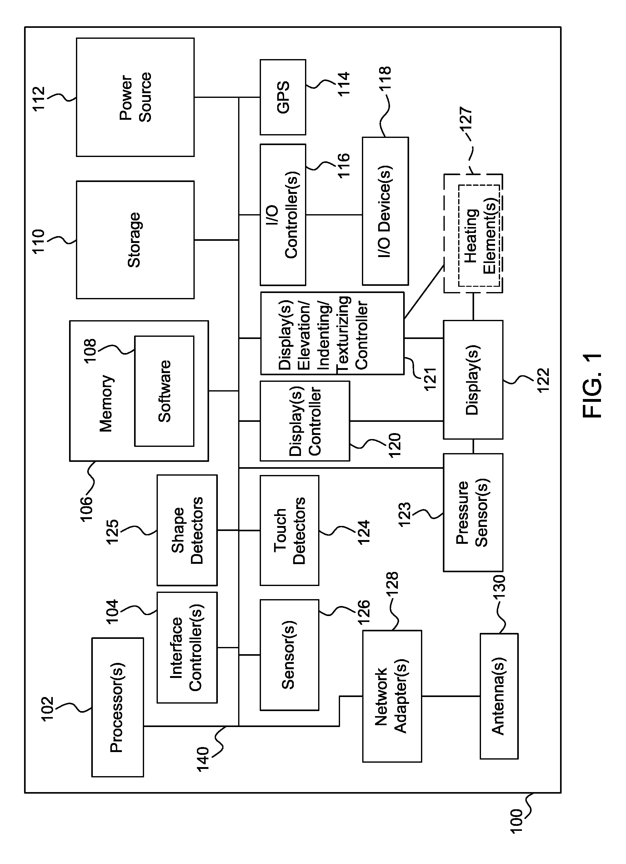
FIG. 1 is a diagram of an electronic device having an elevated, indented, or texturized display device in accordance with one embodiment;
FIGS. 2a-2e are diagrams of elevated, indented, or texturized display devices in accordance with another embodiment;
FIG. 3 is a diagram of an elevated or texturized display device in accordance with another embodiment;
FIG. 4 is a diagram comprising of processes for an electronic device having a display device with elevated, indented, or texturized display portions in accordance with another embodiment;
FIG. 5 is a process for detecting objects or shapes using a display device with an elevated, indented, or texturized display portions in accordance with another embodiment;
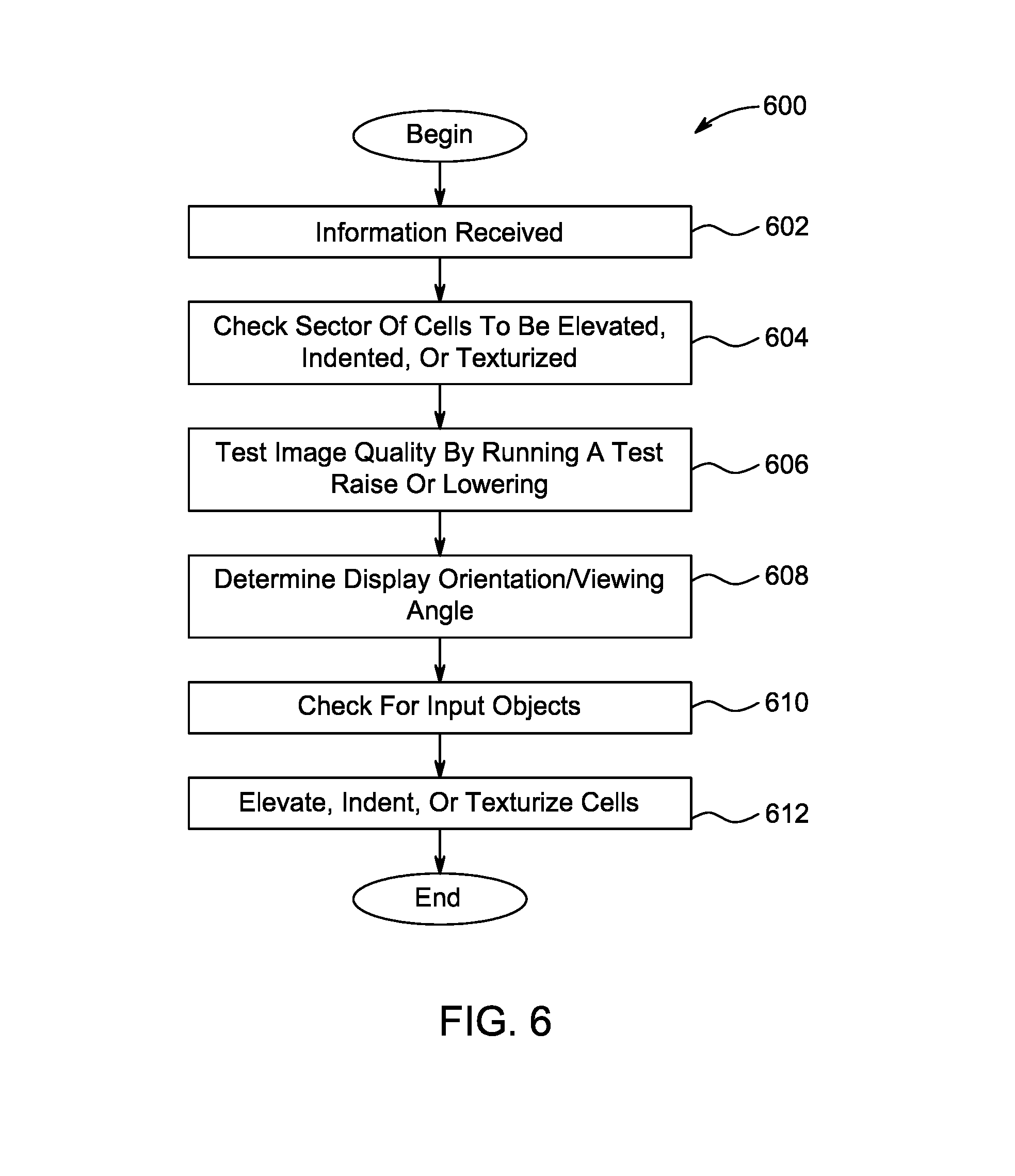
FIG. 6 is a process using an elevated, indented, or texturized display device in accordance with another embodiment; and
FIG. 7 is a process using an elevated, indented, or texturized display device for identifying intellectual property assets in accordance with another embodiment.
DETAILED DESCRIPTION
The present invention will be described with reference to the drawing figures wherein like numerals represent like elements throughout. In the description forthcoming, elevation or elevated describes an orientation where a given surface level is higher or raised relative to another surface level. As an example, the relative elevation may be by one or more millimeters to one or more centimeters or up to an inch. Indenting describes an orientation where a given surface level is lower or depressed relative to another surface level. As an example, the relative indentation may be by one or more millimeters to one or more centimeters. Texturizing or texturing describes a process where a surface provides or mimics friction, variable smoothness, sandpaper like granularity, variable thickness, variable hardness, coarseness, fineness, irregularity, a movement sensation, bumpiness, or rigidness that is sensed by a human touch or detectable by electronic or mechanical sensors.
In addition, lines shown in the accompanying figures for areas having elevated, indented, or texturized portions or cells are for illustrative purposes. Actual display devices may not show lines on the display surface. In addition, in the processes described below the steps recited may be performed out of sequence and substeps not explicitly described or shown may be performed by one of ordinary skill in the art.
FIG. 1 is a diagram of a fixed or mobile subscriber unit, user equipment (UE), mobile station, pager, cellular telephone, personal digital assistant (PDA), computing device, surface computer, monitor, general display, automobile computer system, vehicle computer system, or television device 100 for mobile or fixed applications. Device 100 comprises computer bus 140 that couples one or more processors 102, one or more interface controllers 104, memory 106 having software 108, storage device 110, power source 112, one or more displays controller 120. In addition to one or more displays controller 120, device 100 comprises a display(s) elevation, indenting, or texturizing controller 121 for one or more display devices 122.
One or more display devices 122 can be configured as a liquid crystal display (LCD), light emitting diode (LED), field emission display (FED), organic light emitting diode (OLED), or flexible OLED display device. The one or more display devices 122 may be configured, manufactured, produced, or assembled based on the descriptions provided in US Patent Publication Nos. 2007-247422, 2007-139391, 2007-085838, or 2006-096392 or U.S. Pat. No. 7,050,835 or WO Publication 2007-012899 all herein incorporated by reference as if fully set forth. In the case of a flexible display device, the one or more electronic display devices 122 may be configured and assembled using organic light emitting diodes (OLED), liquid crystal displays using flexible substrate technology, flexible transistors, field emission displays (FED) using flexible substrate technology, as desired. One or more display devices 122 can be configured as a touch screen display using resistive, surface-acoustic wave (SAW) capacitive, infrared, strain gauge, optical imaging, dispersive signal technology, acoustic pulse recognition, frustrated total internal reflection or magneto-strictive technology, as understood by one of ordinary skill in the art.
Coupled to one or more display devices 122 are pressure sensors 123 and optionally heating elements 127. Coupled to computer bus 140 are one or more input/output (I/O) controller 116, I/O devices 118, GPS device 114, one or more network adapters 128, and one or more antennas 130. Device 100 may have one or more motion, light, optical, chemical, environmental, water, acoustic, heat, temperature, radio frequency identification (RFID), biometric, face recognition, image, or voice recognition sensors 126 and touch detectors 124 for detecting any touch inputs, including multi-touch inputs, for one or more display devices 122. One or more interface controller 104 may communicate with touch detectors 124 and I/O controller 116 for determining user inputs to device 100.
Shape detectors 125 may be configured in combination with touch detectors 124, display(s) elevation, indenting, or texturizing controller 121, one or more display devices 122, pressure sensors 123, or sensors 126 to determine the shape, geometry or texture of an object placed on one or more display devices 122, as will be explained in more detail below.
Still referring to device 100, storage device 110 may be any disk based or solid state memory device for storing data. Power source 112 may be a plug-in, battery, solar panels for receiving and storing solar energy, or a device for receiving and storing wireless power as described in U.S. Pat. No. 7,027,311 herein incorporated by reference as if fully set forth. One or more network adapters 128 may be configured as a Time Division Multiple Access (TDMA), Code Division Multiple Access (CDMA), Orthogonal Frequency-Division Multiplexing (OFDM), Orthogonal Frequency-Division Multiple Access (OFDMA), Global System for Mobile (GSM) communications, Enhanced Data rates for GSM Evolution (EDGE), General Packet Radio Service (GPRS), cdma2000, wideband CDMA (W-CDMA), long term evolution (LTE), 802.11x, Wi-Max, mobile Wi-MAX, Bluetooth, or any other wireless or wired transceiver for modulating and demodulating information communicated via one or more antennas 130. Additionally, any of devices, controllers, displays, components, etc. in device 100 may be combined, made integral, or separated as desired.
FIGS. 2a-2e are diagrams of elevated, indented, or texturized display devices. In FIG. 2a layer 204 lays in proximity to display device layer 202 with layer 203 providing separation. Although a single layer is shown, layers 202, 203, and 204 can be composed of a plurality of sublayers. In one embodiment, a particular sublayer within 204 can be transflective to reflect any ambient light and emit white light, such as the average light emitted by surrounding display pixels or cells, so that the displayed image is clear. Display device layer 202 can be either a flexible or rigid display device. Layer 204 can be configured and composed of a clear, flexible, electroactive polymer, polymer composite, or gel material. Electroactive polymers (EAPs), also known as electroactive plastics, can be pulled, expand, contract, deform, change shapes in controllable directions, change dimensions in predetermined directions, or change sizes electronically by applying an electric current, potential difference, voltage, time varying voltage, or electromagnetic fields across the material, as described in U.S. Pat. Nos. 6,117,296, 6,787,238, US Patent Publication No. 2008-188907, US Patent Publication No. 2004-199232, US Patent Publication No. 2005-157893, WO Publication 2007-114699 and "Electric Flex" by Yoseph Bar-Cohen (2001) all herein incorporated by reference as if fully set forth.
Electroactive polymers (EAPs) may be dielectric or ionic EAPs. For dielectric EAPs, actuation can be caused by electrostatic forces between two electrodes that squeeze or compress the polymer. Although requiring a high actuation voltage, dielectric EAPs consume very little power and require no power to keep an actuator at a given position. Examples of dielectric EAPs are electrostrictive polymers and dielectric elastomers that are used for artificial muscles. For Ionic EAPs, actuation is caused by the displacement of ions inside the polymer. Only a few volts are needed for actuation, but the ionic flow implies a higher electrical power needed for actuation, and energy is needed to keep the actuator at a given position. Examples of ionic EAPs are conductive polymers, ionic polymer-metal composites (IPMCs), and responsive gels.
In another embodiment, layer 204 can also be configured and composed of piezoelectric materials or actuators that are bonded to a firm plastic component to form a piezo bending element, as explained in "TPaD: Tactile Pattern Display" by Colgate and Peshkin (2007) herein incorporated by reference as if fully set forth. When a potential difference is applied to a bonded or constricted piezoelectric material it changes shape. The shape change can be controlled electrically to provide different surface textures, indentation, and elevation.
In another embodiment, layer 204 can also be configured and composed of organic transistors formed on a flexible substrate to drive or contract a surface creating texture, indentation, or elevation. Organic transistors are transistors that use organic molecules rather than silicon for their active material. An advantage of organic transistors is the ability to operate on a flexible substrate. Similar to EAPs, organic transistors also exhibit material properties such that they can be pulled, expand, contract, deform, change shapes in controllable directions, change dimensions in predetermined directions, or change sizes electronically by applying an electric current, potential difference, voltage, time varying voltage, or electromagnetic fields.
Still referring to FIG. 2a, portions of surface 216 are selectively elevated, indented, or texturized with one or more substantially cubicle segment 206, dot or dimple segment 208, substantially cylindrical segment 210, bulge segment 212, or indentation segment 214. The shape and texture of the indented or elevated portion depends on the image, document, or application to be displayed and the effects on the resolution of the display device. Because of their natural geometry, certain segments may provide a clearer display of the underlying image or document. Segments 206, 208, 210, 212, and 214 are controlled at least by displays controller 120 and controller 121 that adjust the height, indentation, or depression to multiple different levels, orientation, hardness, thickness, direction, vibration, or gyration individually for each segment. Display(s) elevation, indenting, or texturizing controller 121 may comprise of analog or digital driving circuits (not shown) for driving the segments. Examples of display driving circuits are given in US Patent Publication Nos. 2008-062088, 2006-221016, or 2006-007078 all herein incorporated by reference as if fully set forth.
In FIG. 2a, the operation and configuration of layer 204 may be independent of display device layer 202 thereby simplifying manufacturing since it can be an add-on or attachment to preexisting display systems or technologies. Also, in certain applications images may not be displayed on surface 216 in an area that is elevated, indented, or texturized thereby making it darkened in order to make the area more noticeable to the user. For this configuration, the image displayed on display device layer 202 is rendered to adjust for the darkened area.
FIG. 2b is a diagram of an elevated or texturized display device. Layer 218 lays in proximity to display device layer 220 with layer 219 providing separation. Although a single layer is shown, layers 218, 219, and 220 may be composed of a plurality of sublayers. Display device layer 220 is configured as a flexible display device, such as flexible OLED. Layer 218 may be comprised of the same composition or materials explained above for layer 204 such as EAPs, piezoelectric materials, or organic transistors.
In FIG. 2b, portions of surface 231 are selectively elevated or texturized with one or more substantially cubicle segment 222.sub.1 controlling segment 222.sub.2, dot or dimple segment 224.sub.1 controlling segment 224.sub.2, substantially cylindrical segment 226.sub.1 controlling segment 226.sub.2, or bulge segment 228.sub.1 controlling segment 228.sub.2. Segments 222.sub.2, 224.sub.2, 226.sub.2, and 228.sub.2 are controlled at least by displays controller 120 and/or controller 121 that adjust the height, orientation, direction, or gyration individually or collectively for each segment. Display(s) elevation, indenting, or texturizing controller 121 may comprise of analog or digital driving circuits (not shown) for driving the segments. Since layer 218 is oriented below or behind display device layer 220, there is little interference with the resolution or clarity of images to be displayed on display device layer 220. Also, in certain applications images may not be displayed on surface 231 in an area that is elevated, indented, or texturized thereby making it darkened in order to make the area more noticeable to the user. For this configuration, the image displayed on display device layer 220 is rendered to adjust for the darkened area.
FIG. 2c is a diagram of an elevated, indented, or texturized display device. Display pixels 232.sub.1 to 232.sub.n lay adjacent, on the same level, or on the same layer to elevation, indenting, or texturizing cells 234.sub.1 to 234.sub.n. The display array or matrix 233 also comprises of display pixels 236.sub.1 to 236.sub.n adjacent to elevation, indenting, or texturizing cells 238.sub.1 to 238.sub.n that are adjacent to display pixels 240.sub.1 to 240.sub.n. The elevation, indenting, or texturizing cells may be comprised of the same composition or materials explained above for layer 204 or 218 such as EAPs, piezoelectric material, or organic transistors. Cells 234.sub.1 to 234.sub.n and 238.sub.1 to 238.sub.n are controlled at least by displays controller 120 and/or controller 121 that adjust the height, orientation, direction, or gyration individually or collectively for each cell. Display(s) elevation, indenting, or texturizing controller 121 may comprise of analog or digital driving circuits (not shown) for driving the cells. In this embodiment, cells 234.sub.1 to 234.sub.n and 238.sub.1 to 238.sub.n may be illuminated based on the configuration of surrounding pixels to blend in with any images being displayed.
FIG. 2d shows an embodiment of a display device array or matrix 235 from a top view where elevation, indenting, or texturizing cells 239 are placed selectively within a small area footprint so that the surface of display device array or matrix 235 is mostly comprised of display pixels 237. Having texturizing cells 239 sparsely placed in display device array or matrix 235 ensures minimal interference with a displayed image. In this embodiment the elevation, indented, or texturized cells may be unnoticeable to the human eye but detectable by touch or feeling of display device array or matrix 235.
FIG. 2e is a diagram of an elevated, indented, or texturized display device. In FIG. 2e, display pixels 242 are in the same layer or level but separate from elevation, indenting, or texturizing cells and display pixels areas 244 and 246. FIG. 2e provides a hybrid layout with display pixels 242 operating with selectively placed elevation, indenting, or texturizing cells and display pixels 244 and 246. In FIG. 2e, area 244 can provide scrolling functions while area 246 can be configured as a keyboard, dialpad, keypad, or any other interface.
FIG. 3 is a diagram of an elevated or texturized display device. A matrix of pockets or cells 304.sub.1 to 304.sub.x lays on top of a display device 302. Matrix of pockets or cells 304.sub.1 to 304.sub.x may be full of compressed air or low heat activated gel that becomes elevated or texturized by heating elements 127 as a result of thermal expansion, as understood by one of ordinary skill in the art. Matrix of pockets or cells 304.sub.1 to 304.sub.x can be tapered but flat and seamless when unexpanded. Moreover, heating elements 127 can be used to provide different tactile sensations in combination with pockets or cells 304.sub.1 to 304.sub.x. so that a user is provided varying temperatures, such as hot or cold information, relating to a displayed image.
FIG. 4 is a diagram illustrating processes for an electronic device having a display device 402 with elevated, indented, or texturized display portions. Display device 402 can be assembled with at least some of the components described in device 100. For elevated, indented, or texturized applications, display device 402 may be configured with the devices described in FIG. 2a, 2c, or 2d, as desired. For elevated or certain texturized applications, display device 402 may be configured with the devices described in FIG. 2b or 3, as desired. For illustrative purposes, in FIG. 4 a darkened or black portion represents an indented portion, a white portion represents an elevated portion, and a checkered pattern represents a texturized portion.
For inputting data or triggering a request action, a "click here" displayed link is provided with a combination of an indented portion 404.sub.1 and elevated portion 404.sub.2. Moreover, part of a virtual or simulated keyboard displayed on display device 402 provides the letter "E" key with a partially displayed portion 406, an elevated circular portion 414 and an elevated square portion 408. Although part of a virtual or simulated keyboard is shown, display device 402 can be configured to show a whole QWERTY keyboard, a numbered keypad for dialing, or a combination of a whole QWERTY keyboard and a numbered keypad, as desired. The letter "S" key is provided by a partially displayed portion and an elevated circular portion 410. The letter "Q" key is completely elevated by portion 412. The virtual or simulated keyboard can also be programmed to replicate Braille lettering, as desired.
In addition to key inputs, portions 414, 408, 410, or 412 can detect different pressure forces when pushed down, pushed sideways, or pulled sideways providing another metric or advantage for the man machine interface. For instance, a pull in one direction may indicate a capital letter input while a push in another direction may indicate subscripting of the letter. These different pressure forces are detected by pressure sensors 123 in combination with touch detectors 124 and/or display(s) elevation, indenting, or texturizing controller 121 by measuring gradient, force, or potential difference values. Moreover, in response to a detected force by pressure sensors 123 and touch detectors 124, haptic feedback, force feedback or tactile feedback in the form of a played sound, gyration, or vibration can be provided via I/O controller 116.
Still referring to the virtual or simulated keyboard on display device 402, instructions in software 108 can be used to predict or anticipate keystrokes based on a word or sentence entered. In response to the anticipation, different keys can be raised, indented, or texturized in order to increase typing speeds.
An embodiment of the present invention provides electronic advertising processes. Advertisement 416 can be sold to an advertiser for a certain price for having elevated portions 416.sub.1 and 416.sub.3 and indentation 416.sub.2 on at least one part or the entire advertisement. Advertisement 418 can be sold to an advertiser for a different price, higher or lower, for having elevated portions 418.sub.1 and 418.sub.2 having different heights from other advertisements and can be based in combination with location determined by GPS device 114. Advertisement 419 can be sold to an advertiser for a different price for having a plurality of elevated, indented, or texturized portions 419.sub.1.
An embodiment of the present invention provides electronic business processes. A "Buy Now" button is provided with an elevated circular portion 422.sub.1 and a square portion 422.sub.2. The "Buy Now" button is associated with triggering the purchasing of shirt 424 by sending a request to a server (not shown) over one or more network adapters 128. For shirt 424, a texturizing portion 426 is provided to replicate or simulate the surface of shirt 424. Texturizing portion 426 can be a combination of elevated and indented cells. Although a shirt 424 is shown, texturizing portion 426 can be used to provide surface information for any product being sold or displayed on display device 402 such as electronics, home goods, jewelry, etc.
Using touch detectors 124 in combination with display(s) elevation, indenting, or texturizing controller 121, shirt 424 can be rotated in response to a multitouch input while texturizing portion 426 is dynamically changed to reflect the different surfaces or materials used in the product. Shirt 424 can be zoomed in and out using multitouch inputs detected by touch detectors 124 with each zoom level reflecting texture differences on portion 426. For instance, a zoomed in view can be more grainy or rough compared to a zoomed out view. The zoom levels can also be configured with a fading in or out effect by one or more processors 102 and can involve retrieving additional information from a server (not shown) over one or more network adapters 128. Moreover, if certain rare or uncommon materials cannot be replicated or simulated by texturizing portion 426, legend 425 identifies or associates different materials, such as rabbit skin, llama wool, and rare silk, by texturized portions 425.sub.1, 425.sub.2, and 425.sub.3, respectively. Beyond the examples of fabrics, other materials like metals, plastics, glass, wood, etc. can be replicated or simulated by texturizing portion 426.
Still referring to FIG. 4, an embodiment of the present invention provides an electronic game with elevated, indented, or texturizing portion 428 (hereinafter "portion 428"), such as tic-tac-toe. Portion 428 can detect different pressure forces when pushed down, pushed sideways, or pulled sideways providing another metric or feature for the man machine interface. These different pressure forces can be detected by pressure sensors 123 in combination with touch detectors 124 and/or display(s) elevation, indenting, or texturizing controller 121 by measuring gradient, force, or potential difference values of touches to raised portions in portion 428. Another gaming application comprises portion 428 emulating a piano or guitar.
Moreover, a game can receive as inputs flicks, pinches, or scratches to portion 428 and generate an action on display device 402 in response to each detected action differently. A pinch to a raised portion of 428 can represent an object or block being picked up or opened in a game or any other simulated environment. Portion 428 can also control scrolling or drag and drop functions in combination with multitouch inputs detected by touch detectors 124. In another embodiment, certain portions 428 can be used as a miniature joystick or pointing stick for 360 degrees rotational input that is detected by pressure sensors 123 in combination with touch detectors 124 and/or display(s) elevation, indenting, or texturizing controller 121. A three dimensional accelerometer can be included in sensors 126 to be used in combination with display(s) elevation, indenting, or texturizing controller 121 to raise part of portion 428 in response to a programmed action in the game. Portion 428 can also be used to simulate or replicate a lottery scratching/rubbing game or a children's productivity game, as desired. Portion 428 can also provide a gaming feature where tilting or rotation detected by an accelerometer in sensors 126 raises some portions while indenting others for four dimensional motion gaming.
In another embodiment, portion 428 can provide online collaboration, online conferencing, social networking, or online dating. In response to push or pull input on a networked computing device (not shown) having an elevated, indented, or texturized display device, portion 428 provides feedback, similar to a poke on Facebook. In online conferencing, tactile inputs to portion 428 can be used during a video conference application for additional interaction between conversing parties. For social networking, adult entertainment can be enhanced by portion 428 providing stimulation in connection with a video, image, or audio media on display device 402.
Additional processes exist within the medical field for online collaboration. Portion 428 can provide remote medical diagnostics and measurements, such as a pressure test, over a network using one or more network adapters 128 and pressure sensors 123 in combination with touch detectors 124 and/or display(s) elevation, indenting, or texturizing controller 121. Diagnostics and measurements include tactile for motor skills, respiratory for testing lung pressure by a person blowing on portion 428, or muscular by measuring range of motion and strength, as desired. Therefore, portion 428 can provide bi-directional information exchange.
Still referring to medical processes, portion 428 can be used for the elderly or disabled to provide simple, small scale physical therapy exercises for the hand or fingers by allowing a user to pull raised portions at different tensions and resistances or pickup objects. This is particularly useful for stroke victims by providing mental therapy, exercises and massaging of small muscles and ligaments.
In another embodiment, portion 428 can be used to provide a plurality of processes or applications. Portion 428 can simulate maps, topography, geography, imagery, or location service processes in combination with GPS device 114. Portion 428 can display mountainous regions on a map by elevating and oceans by indenting. Portion 428 can follow a musical sequence being played on device 100 for a ringtone during a received call or song. Moreover, portion 428 can be used to display content in an email, 3rd Generation Partnership Project (3GPP) or 3GPP2 short message service (SMS) text message, 3GPP or 3GPP2 multimedia message service (MMS) message, an image or video motion in an MMS message, PDF application, word document, excel graphs, excel charts, four dimensional (4-D) screensaver, 4-D art, 4-D drawings, 3-D imagery, a 3-D sculpture, a 4-D "etch-a-sketch", or architecture designs using scalable or vector graphics. Any of the content given above and displayed by portion 428 may be transmitted or received over one or more network adapters 128.
Moreover, portion 428 can provide, replicate, or simulate integrated circuit layouts, electrical circuit layouts, facial features, enhanced video clips, computer aided designs (CAD), semiconductor layouts, prototyping, modeling, molding for producing form factors, logos, trademarks, a children's educational product, a general education product, a 3-D drawing tool, distance learning, or a pop-up children's books, as desired. In addition, portion 428 can be responsive to voice or visual commands or recognition detected by sensors 126 for being elevated, indented, or texturized.
Moreover, portion 428 can provide object awareness to display device 402. For instance, a post it note can be detected when it is determined that there is additional resistivity or elasticity by the adhesive on the post it note by pressure sensors 123 and in combination with touch detectors 124 and/or display(s) elevation, indenting, or texturizing controller 121 to raised or elevated cell in portion 428. In response to the detected post it, display device 402 can adapt and reformat the images around the note such that images are not obstructed to the user.
Moreover, portion 428 can provide advanced Bluetooth capabilities for Bluetooth keyboards, headsets and can function as a Bluetooth device itself for medical applications. When a call is received over one or more network adapters 128, a preprogrammed texturized pattern is reproduced on portion 428 for notifying the user, such as when display device 402 is in a shirt pocket in hands-free mode communicating with a wireless headset. Alternatively, the texturized pattern reproduced on portion 428 during an incoming call can be controlled, designed, or customized by the calling party if the function is enabled on device 100.
Still referring to FIG. 4, another embodiment provides object detection for a 3-D object that is placed on area 429 having a combination of elevated cells, indented cells, and/or texturized cells. FIG. 5 is a process 500 for detecting objects or shapes using elevated, indented, or texturized display portions. Although process 500 can be performed by device 100 in a fat client architecture, device 100 can also be configured as a thin client by sharing shape detection processing functions with a server (not shown) using one or more network adapters 128. Cells are selectively raised around an object placed on area 429 by display(s) elevation, indenting, or texturizing controller 121 (step 502). The weight of the object is detected by pressure sensors 123 and shape detectors 125 and a height graph of the surface of the object is generated by one or more processors 102 (step 504). The perimeter of the object placed on area 429 is determined by one or more processors 102 and shape detectors 125 by raising or lowering cells in proximity to object by display(s) elevation, indenting, or texturizing controller 121 (step 506). One or more processors 102 calculate gradients values (step 508) and generates a surface graph (step 510) based on the previous measurements made.
Moreover, display device 402 may have infrared detectors 430.sub.1-430.sub.4 in a slightly beveled position or in the level with the frame of display device 402. Display device 402 may also have digital cameras 434.sub.1-434.sub.4 for capturing, tracking, and detecting shapes using algorithms such as that described in U.S. Pat. No. 7,317,872, herein incorporated by reference as if fully set forth, that can be used to perform additional sensor measurements (step 512). Other sensor measurements for additional metrics and refinement include infrared or optical detection to detect depth. These sensors can be embedded next to or within each display cell in display device 402. Based on steps 502-512, a preliminary image may be rendered by one or more processors 102. The preliminary image can be compared and matched against a database of images in storage 110, or stored remotely, using artificial intelligence algorithms. Information is then retrieved by one or more network adapters 128 based on the detected object and/or preliminary image (step 514).
In a process involving area 429 and process 500, a ring size is detected and related information, such as from an online jewelry stored, is retrieved over one or more network adapters in response. Alternatively, the size and type of certain household goods, such as hardware, screws, nuts, light bulbs, batteries can be determined by area 429 and process 500. Moreover, a key placed on area 429 can be keyed and the information sent over one or more network adapters 128 for subsequent duplication and mail delivery by an online store. In addition, process 500 can be used to obtain biometric information for security purposes.
In another process involving area 429, intellectual property assets, such as patents, trademarks, or copyrights, relating to the shape of a detected object is retrieved and displayed in a map format in display device 402 to show a correspondence between similar features of an object and related intellectual property assets. FIG. 7 is a process using an elevated, indented, or texturized display device for identifying intellectual property assets. The shape of a widget 702 placed on area 429 is detected by process 500 and digitally rendered. The detected shape of the widget 702 is compared against widgets 706.sub.1, 706.sub.2, or 706.sub.3 shown and described in U.S. Pat. No. X (704) stored in a database. The comparison between widgets can be performed graphically using image rendering, as understood to one of ordinary skill in the art. Moreover, artificial intelligence algorithms can be used to compare claim text or descriptions 710 in U.S. Pat. No. X (704) against features detected by area 429 and process 500. If a match is determined or found, the widget 702 is associated with U.S. Pat. No. X (708) and displayed in a map format on display device 402.
In another embodiment, display device 402 replicates, mimics, or simulates a customizable or programmable interface or control panel for a remote control, instrument panel on a vehicle, an automobile dashboard configuration, audio equalizers, multitouch equalizers, radio button list, or a consumer electronics button surface with raised button portions 432.sub.1-432.sub.3. The simulated interface can be used to sell consumer electronics or function as an advanced user guide whereby input, output, and programming functions are simulated with button portions 432.sub.1-432.sub.3 that have the same size and shape as the actual buttons on a product. Moreover, 432.sub.1-432.sub.3 can be programmed for controlling volume control, replicating smart home switches or controllers, as desired.
Still referring to FIG. 4, advanced web searching 436 is performed by measuring pressure applied or detecting depth perception to raised or elevated portion 438. Web searching 436 can be used in combination with area 429 to display hits or webpages relevant to detected objects.
FIG. 6 is a process 600 using an elevated, indented, or texturized display device that can be selectively performed by the display devices described above. Information is received from one or more network adapters 128, I/O devices 118, or storage device 110 (step 602). The sector of cells to be elevated, indented, or texturized based on the received information is checked and tested by display(s) elevation, indenting, or texturizing controller 121 and display controllers 120 (step 604) to determine how a high image quality in the area can be maintained (step 606) by raising or lowering selective cells. One or more processors 102 in combination with sensors 126 determine display orientation or viewing angle (step 608) that is taken into consideration to properly elevate, indent, or texturize the display devices described above. If an image of an object is to be simulated or replicated, it is rendered by one or more processors 102 and checked to determine if it can be properly displayed (step 610). The cells in the display device are elevated, indented, or texturized (step 612).
Although features and elements are described above in particular combinations, each feature or element can be used alone without the other features and elements or in various combinations with or without other features and elements. The methods, processes, or flow charts provided herein may be implemented in a computer program, software, or firmware incorporated in a computer-readable storage medium for execution by a general purpose computer or a processor. Examples of computer-readable storage mediums include a read only memory (ROM), a random access memory (RAM), a register, cache memory, semiconductor memory devices, magnetic media such as internal hard disks and removable disks, magneto-optical media, and optical media such as CD-ROM disks, digital versatile disks (DVDs), and BluRay discs.
Suitable processors include, by way of example, a general purpose processor, a special purpose processor, a conventional processor, a digital signal processor (DSP), a plurality of microprocessors, one or more microprocessors in association with a DSP core, a controller, a microcontroller, Application Specific Integrated Circuits (ASICs), Field Programmable Gate Arrays (FPGAs) circuits, any other type of integrated circuit (IC), and/or a state machine.
A processor in association with software may be used to implement a radio frequency transceiver for use in a computer, wireless transmit receive unit (WTRU), user equipment (UE), terminal, base station, radio network controller (RNC), or any host computer. The WTRU may be used in conjunction with modules, implemented in hardware and/or software, such as a camera, a video camera module, a videophone, a speakerphone, a vibration device, a speaker, a microphone, a television transceiver, a hands free headset, a keyboard, a Bluetooth.RTM. module, a frequency modulated (FM) radio unit, a liquid crystal display (LCD) display unit, an organic light-emitting diode (OLED) display unit, a digital music player, a media player, a video game player module, an Internet browser, and/or any wireless local area network (WLAN) or Ultra Wide Band (UWB) module.
* * * * *
References
D00000
D00001
D00002
D00003
D00004
D00005
D00006
D00007
D00008
XML
uspto.report is an independent third-party trademark research tool that is not affiliated, endorsed, or sponsored by the United States Patent and Trademark Office (USPTO) or any other governmental organization. The information provided by uspto.report is based on publicly available data at the time of writing and is intended for informational purposes only.
While we strive to provide accurate and up-to-date information, we do not guarantee the accuracy, completeness, reliability, or suitability of the information displayed on this site. The use of this site is at your own risk. Any reliance you place on such information is therefore strictly at your own risk.
All official trademark data, including owner information, should be verified by visiting the official USPTO website at www.uspto.gov. This site is not intended to replace professional legal advice and should not be used as a substitute for consulting with a legal professional who is knowledgeable about trademark law.