Remote sensing of remaining battery capacity using on-battery circuitry
Bourilkov , et al. Ja
U.S. patent number 10,184,988 [Application Number 15/413,334] was granted by the patent office on 2019-01-22 for remote sensing of remaining battery capacity using on-battery circuitry. This patent grant is currently assigned to DURACELL U.S. OPERATIONS, INC.. The grantee listed for this patent is DURACELL U.S. OPERATIONS, INC.. Invention is credited to Jordan Todorov Bourilkov, Sergio Coronado Hortal, Steven Jeffrey Specht.


| United States Patent | 10,184,988 |
| Bourilkov , et al. | January 22, 2019 |
Remote sensing of remaining battery capacity using on-battery circuitry
Abstract
A method of remote sensing a charge includes charging or discharging a first capacitor of a first RC circuit and a second capacitor of a second RC circuit to a predetermined threshold voltage using a power source. When each of the capacitors reach the predetermined threshold voltage, a response signal is provided from a communications module to a handheld computing device comprising a reader system. An amount of time between the response signals is determined. The amount of time is indicative of charge information.
| Inventors: | Bourilkov; Jordan Todorov (Bethany, CT), Coronado Hortal; Sergio (Bethel, CT), Specht; Steven Jeffrey (Brookfield, CT) | ||||||||||
|---|---|---|---|---|---|---|---|---|---|---|---|
| Applicant: |
|
||||||||||
| Assignee: | DURACELL U.S. OPERATIONS, INC.
(Wilmington, DE) |
||||||||||
| Family ID: | 49958680 | ||||||||||
| Appl. No.: | 15/413,334 | ||||||||||
| Filed: | January 23, 2017 |
Prior Publication Data
| Document Identifier | Publication Date | |
|---|---|---|
| US 20170131365 A1 | May 11, 2017 | |
Related U.S. Patent Documents
| Application Number | Filing Date | Patent Number | Issue Date | ||
|---|---|---|---|---|---|
| 14041014 | Sep 30, 2013 | 9551758 | |||
| 61746265 | Dec 27, 2012 | ||||
| Current U.S. Class: | 1/1 |
| Current CPC Class: | G01R 31/371 (20190101); G01R 31/385 (20190101); G01R 31/388 (20190101); G01R 31/3835 (20190101); G01R 31/382 (20190101) |
| Current International Class: | G01R 31/36 (20060101) |
| Field of Search: | ;702/63 ;320/132 ;324/427 |
References Cited [Referenced By]
U.S. Patent Documents
| 3354565 | November 1967 | Emmons et al. |
| 3992228 | November 1976 | Depoix |
| 3993985 | November 1976 | Chopard et al. |
| 4117475 | September 1978 | Ebihara et al. |
| 4149146 | April 1979 | Ebihara et al. |
| 4238554 | December 1980 | Barrella |
| 4302751 | November 1981 | Nakauchi et al. |
| 4460870 | July 1984 | Finger |
| 4482615 | November 1984 | Rosansky et al. |
| 4598243 | July 1986 | Kawakami |
| 4654280 | March 1987 | Bailey |
| 4759765 | July 1988 | Van Kampen |
| 4808497 | February 1989 | Blomgren et al. |
| 4860185 | August 1989 | Brewer et al. |
| 4952330 | August 1990 | Leger et al. |
| 5015544 | May 1991 | Burroughs et al. |
| 5032825 | July 1991 | Kuznicki |
| 5219683 | June 1993 | Webber |
| 5231356 | July 1993 | Parker |
| 5250905 | October 1993 | Kuo et al. |
| 5290414 | March 1994 | Marple |
| 5339024 | August 1994 | Kuo et al. |
| 5355089 | October 1994 | Treger |
| 5366832 | November 1994 | Hayashi et al. |
| 5389458 | February 1995 | Weiss et al. |
| 5389470 | February 1995 | Parker et al. |
| 5396177 | March 1995 | Kuo et al. |
| 5418086 | May 1995 | Bailey |
| 5424722 | June 1995 | Inada et al. |
| 5438607 | August 1995 | Przygoda, Jr. et al. |
| 5458992 | October 1995 | Bailey |
| 5458997 | October 1995 | Crespi et al. |
| 5491038 | February 1996 | DePalma et al. |
| 5494496 | February 1996 | Huhndorff et al. |
| 5514491 | May 1996 | Webber |
| 5525439 | June 1996 | Huhndorff et al. |
| 5543246 | August 1996 | Treger |
| 5569556 | October 1996 | Bohmer |
| 5587573 | December 1996 | Owen et al. |
| 5596278 | January 1997 | Lin |
| 5607790 | March 1997 | Hughen et al. |
| 5627472 | May 1997 | Ofer et al. |
| 5633592 | May 1997 | Lang |
| 5640150 | June 1997 | Atwater |
| 5691083 | November 1997 | Bolster |
| 5737114 | April 1998 | Bailey |
| 5786106 | July 1998 | Armani |
| 5798933 | August 1998 | Nicolai |
| 5849046 | December 1998 | Bailey |
| 5925479 | July 1999 | Wei et al. |
| 5959568 | September 1999 | Woolley |
| 5963012 | October 1999 | Garcia et al. |
| 6014014 | January 2000 | Owen et al. |
| 6084523 | July 2000 | Gelnovatch et al. |
| 6127062 | October 2000 | Sargeant et al. |
| 6143439 | November 2000 | Yoppolo et al. |
| 6156450 | December 2000 | Bailey |
| 6169397 | January 2001 | Steinbach et al. |
| 6171729 | January 2001 | Gan et al. |
| 6208235 | March 2001 | Trontelj |
| 6218054 | April 2001 | Webber |
| 6252377 | June 2001 | Shibutani |
| 6275161 | August 2001 | Wan et al. |
| 6300004 | October 2001 | Tucholski |
| 6407534 | June 2002 | Mukainakano |
| 6469471 | October 2002 | Anbuky et al. |
| 6483275 | November 2002 | Nebrigic et al. |
| 6587250 | July 2003 | Armgarth et al. |
| 6617069 | September 2003 | Hopper et al. |
| 6617072 | September 2003 | Venkatesan et al. |
| 6627353 | September 2003 | Munshi |
| 6670073 | December 2003 | Tucholski et al. |
| RE38518 | May 2004 | Tucholski |
| 6730136 | May 2004 | Webber |
| 6774685 | August 2004 | O'Toole et al. |
| 6775562 | August 2004 | Owens et al. |
| 6849360 | February 2005 | Marple |
| 6979502 | December 2005 | Gartstein et al. |
| 7067882 | June 2006 | Singh |
| 7079079 | July 2006 | Jo et al. |
| 7157185 | January 2007 | Marple |
| 7386404 | June 2008 | Cargonja et al. |
| 7474230 | January 2009 | Blom et al. |
| 7489431 | February 2009 | Malmstrom et al. |
| 7511454 | March 2009 | Legg |
| 7561050 | July 2009 | Bhogal et al. |
| 7576517 | August 2009 | Cotton et al. |
| 7586416 | September 2009 | Ariyoshi et al. |
| 7598880 | October 2009 | Powell et al. |
| 7606530 | October 2009 | Anderson et al. |
| 7715884 | May 2010 | Book et al. |
| 7741970 | June 2010 | Cunningham et al. |
| 7745046 | June 2010 | Kim et al. |
| 7768236 | August 2010 | Takamura et al. |
| 7772850 | August 2010 | Bertness |
| 7805263 | September 2010 | MacK |
| 7911182 | March 2011 | Cargonja et al. |
| 7944368 | May 2011 | Carter et al. |
| 8031054 | October 2011 | Tuttle |
| 8106845 | January 2012 | Savry |
| 8119286 | February 2012 | Issaev et al. |
| 8131486 | March 2012 | Leonard et al. |
| 8344685 | January 2013 | Bertness et al. |
| 8368356 | February 2013 | Nakashima et al. |
| 8424092 | April 2013 | Ikeuchi et al. |
| 8427109 | April 2013 | Melichar |
| 8471888 | June 2013 | George et al. |
| 8652670 | February 2014 | Uchida |
| 8653926 | February 2014 | Detcheverry et al. |
| 8900731 | December 2014 | Bohne |
| 8905317 | December 2014 | Hsu et al. |
| 9037426 | May 2015 | Schaefer |
| 9060213 | June 2015 | Jones |
| 9076092 | July 2015 | Ritamaki et al. |
| 9083063 | July 2015 | Specht et al. |
| 9146595 | September 2015 | Forutanpour et al. |
| 9167317 | October 2015 | DeMar |
| 9189667 | November 2015 | Bourilkov et al. |
| 9235044 | January 2016 | Specht et al. |
| 9297859 | March 2016 | Mukaitani et al. |
| 9312575 | April 2016 | Stukenberg et al. |
| 9331378 | May 2016 | Merlin et al. |
| 9453885 | September 2016 | Mukaitani et al. |
| 9459323 | October 2016 | Mukaitani et al. |
| 9461339 | October 2016 | Roohparvar |
| 9478850 | October 2016 | Bourilkov et al. |
| 9551758 | January 2017 | Bourilkov et al. |
| 9568556 | February 2017 | Bourilkov et al. |
| 9619612 | April 2017 | Kallfelz et al. |
| 9639724 | May 2017 | Bourilkov et al. |
| 9661576 | May 2017 | Tomisawa |
| 9699818 | July 2017 | Grothaus et al. |
| 9726763 | August 2017 | Dempsey et al. |
| 9739837 | August 2017 | Bourilkov et al. |
| 9746524 | August 2017 | Petrucelli |
| 9823310 | November 2017 | Bourilkov et al. |
| 9841462 | December 2017 | Kim et al. |
| 9843220 | December 2017 | Herrmann et al. |
| 9869726 | January 2018 | Zumstein et al. |
| 9882250 | January 2018 | Chappelle et al. |
| 9887463 | February 2018 | Bourilkov et al. |
| 9893390 | February 2018 | Specht et al. |
| 9983312 | May 2018 | Dempsey et al. |
| 2001/0005123 | June 2001 | Jones et al. |
| 2001/0026226 | October 2001 | Andersson et al. |
| 2002/0001745 | January 2002 | Gartstein et al. |
| 2002/0086718 | July 2002 | Bigwood et al. |
| 2003/0070283 | April 2003 | Webber |
| 2003/0169047 | September 2003 | Chen |
| 2003/0170537 | September 2003 | Randell |
| 2003/0184493 | October 2003 | Robinet et al. |
| 2003/0228518 | December 2003 | Marple |
| 2004/0029007 | February 2004 | Kusumoto et al. |
| 2004/0048512 | March 2004 | Chen |
| 2004/0183742 | September 2004 | Goff et al. |
| 2005/0038614 | February 2005 | Botts et al. |
| 2005/0073282 | April 2005 | Carrier et al. |
| 2005/0095508 | May 2005 | Yamamoto |
| 2005/0112462 | May 2005 | Marple |
| 2005/0162129 | July 2005 | Mutabdzija et al. |
| 2005/0233214 | October 2005 | Marple et al. |
| 2005/0277023 | December 2005 | Marple et al. |
| 2006/0017581 | January 2006 | Schwendinger et al. |
| 2006/0043933 | March 2006 | Latinis |
| 2006/0046152 | March 2006 | Webber |
| 2006/0046153 | March 2006 | Webber |
| 2006/0046154 | March 2006 | Webber et al. |
| 2006/0047576 | March 2006 | Aaltonen et al. |
| 2006/0163692 | July 2006 | Detecheverry et al. |
| 2006/0168802 | August 2006 | Tuttle |
| 2006/0170397 | August 2006 | Srinivasan et al. |
| 2006/0208898 | September 2006 | Swanson et al. |
| 2006/0247156 | November 2006 | Vanderby et al. |
| 2006/0261960 | November 2006 | Haraguchi et al. |
| 2007/0080804 | April 2007 | Hirahara et al. |
| 2007/0096697 | May 2007 | Maireanu |
| 2007/0108946 | May 2007 | Yamauchi et al. |
| 2007/0182576 | August 2007 | Proska et al. |
| 2007/0210924 | September 2007 | Arnold et al. |
| 2007/0273329 | November 2007 | Kobuse et al. |
| 2008/0053716 | March 2008 | Scheucher |
| 2008/0076029 | March 2008 | Bowden et al. |
| 2008/0079391 | April 2008 | Schroeck et al. |
| 2008/0157924 | July 2008 | Batra |
| 2008/0160392 | July 2008 | Toya et al. |
| 2008/0206627 | August 2008 | Wright |
| 2008/0252462 | October 2008 | Sakama |
| 2009/0008031 | January 2009 | Gould et al. |
| 2009/0009177 | January 2009 | Kim et al. |
| 2009/0024309 | January 2009 | Crucs |
| 2009/0041228 | February 2009 | Owens et al. |
| 2009/0098462 | April 2009 | Fujiwara et al. |
| 2009/0148756 | June 2009 | Specht et al. |
| 2009/0155673 | June 2009 | Northcott |
| 2009/0179763 | July 2009 | Sheng |
| 2009/0214950 | August 2009 | Bowden et al. |
| 2009/0263727 | October 2009 | Josephs et al. |
| 2009/0273473 | November 2009 | Tuttle |
| 2009/0289825 | November 2009 | Trinkle |
| 2009/0297949 | December 2009 | Berkowitz et al. |
| 2010/0019733 | January 2010 | Rubio |
| 2010/0081049 | April 2010 | Holl et al. |
| 2010/0085008 | April 2010 | Suzuki et al. |
| 2010/0087241 | April 2010 | Nguyen et al. |
| 2010/0143753 | June 2010 | Kim et al. |
| 2010/0209744 | August 2010 | Kim |
| 2010/0219252 | September 2010 | Kikuchi et al. |
| 2010/0295943 | November 2010 | Cha et al. |
| 2010/0308974 | December 2010 | Rowland et al. |
| 2011/0023130 | January 2011 | Gudgel et al. |
| 2011/0104520 | May 2011 | Ahn |
| 2011/0123874 | May 2011 | Issaev et al. |
| 2011/0163752 | July 2011 | Janousek et al. |
| 2011/0293969 | December 2011 | Hoofman et al. |
| 2012/0021266 | January 2012 | Marple et al. |
| 2012/0056002 | March 2012 | Ritamaki et al. |
| 2012/0081774 | April 2012 | De Paiva Martins et al. |
| 2012/0086615 | April 2012 | Norair |
| 2012/0121943 | May 2012 | Roohparvar |
| 2012/0183862 | July 2012 | Gupta et al. |
| 2012/0190305 | July 2012 | Wuidart |
| 2012/0206102 | August 2012 | Okamura et al. |
| 2012/0206302 | August 2012 | Ramachandran et al. |
| 2012/0217971 | August 2012 | Deluca |
| 2012/0235870 | September 2012 | Forster |
| 2012/0277832 | November 2012 | Hussain |
| 2012/0299597 | November 2012 | Shigemizu |
| 2012/0323511 | December 2012 | Saigo et al. |
| 2013/0069768 | March 2013 | Madhyastha et al. |
| 2013/0127611 | May 2013 | Bernstein et al. |
| 2013/0148283 | June 2013 | Forutanpour et al. |
| 2013/0154652 | June 2013 | Rice et al. |
| 2013/0161380 | June 2013 | Joyce et al. |
| 2013/0162402 | June 2013 | Amann et al. |
| 2013/0162403 | June 2013 | Striemer et al. |
| 2013/0162404 | June 2013 | Striemer et al. |
| 2013/0164567 | June 2013 | Olsson et al. |
| 2013/0183568 | July 2013 | Babinec et al. |
| 2013/0185008 | July 2013 | Itabashi et al. |
| 2013/0271072 | October 2013 | Lee et al. |
| 2013/0295421 | November 2013 | Teramoto et al. |
| 2013/0320989 | December 2013 | Inoue et al. |
| 2014/0062663 | March 2014 | Bourilkov et al. |
| 2014/0139380 | May 2014 | Ouyang et al. |
| 2014/0188413 | July 2014 | Bourilkov et al. |
| 2014/0229129 | August 2014 | Campbell et al. |
| 2014/0302348 | October 2014 | Specht et al. |
| 2014/0302351 | October 2014 | Specht et al. |
| 2014/0320144 | October 2014 | Nakaya |
| 2014/0342193 | November 2014 | Mull et al. |
| 2014/0346873 | November 2014 | Colangelo et al. |
| 2014/0347249 | November 2014 | Bourilkov et al. |
| 2014/0370344 | December 2014 | Lovelace et al. |
| 2014/0379285 | December 2014 | Dempsey et al. |
| 2015/0061603 | March 2015 | Loftus et al. |
| 2015/0064524 | March 2015 | Noh et al. |
| 2015/0349391 | December 2015 | Chappelle et al. |
| 2016/0034733 | February 2016 | Bourilkov et al. |
| 2016/0049695 | February 2016 | Lim et al. |
| 2016/0064781 | March 2016 | Specht et al. |
| 2016/0092847 | March 2016 | Buchbinder |
| 2016/0137088 | May 2016 | Lim et al. |
| 2016/0277879 | September 2016 | Daoura et al. |
| 2017/0040698 | February 2017 | Bourilkov et al. |
| 2017/0062841 | March 2017 | Riemer et al. |
| 2017/0062880 | March 2017 | Riemer et al. |
| 2017/0092994 | March 2017 | Canfield et al. |
| 2017/0125855 | May 2017 | Gong et al. |
| 2017/0176539 | June 2017 | Younger |
| 2017/0286918 | October 2017 | Westermann et al. |
| 2017/0301961 | October 2017 | Kim et al. |
| 2017/0315183 | November 2017 | Chao et al. |
| 2017/0331162 | November 2017 | Clarke et al. |
| 2018/0040929 | February 2018 | Chappelle et al. |
| 2018/0088182 | March 2018 | Bourilkov et al. |
| 2018/0120386 | May 2018 | Riemer et al. |
| 2018/0123174 | May 2018 | Riemer et al. |
| 2018/0123175 | May 2018 | Riemer et al. |
| 2018/0123176 | May 2018 | Riemer et al. |
| 2018/0123233 | May 2018 | Bourilkov et al. |
| 1084281 | Mar 1994 | CN | |||
| 1228540 | Sep 1999 | CN | |||
| 1315072 | Sep 2001 | CN | |||
| 2828963 | Oct 2006 | CN | |||
| 101126795 | Feb 2008 | CN | |||
| 201142022 | Oct 2008 | CN | |||
| 101702792 | May 2010 | CN | |||
| 101785164 | Jul 2010 | CN | |||
| 102097844 | Jun 2011 | CN | |||
| 102142186 | Aug 2011 | CN | |||
| 102544709 | Jul 2012 | CN | |||
| 202720320 | Feb 2013 | CN | |||
| 103682482 | Mar 2014 | CN | |||
| 104635169 | May 2015 | CN | |||
| 105337367 | Feb 2016 | CN | |||
| 205160145 | Apr 2016 | CN | |||
| 106405241 | Feb 2017 | CN | |||
| 106848448 | Jun 2017 | CN | |||
| 107284272 | Oct 2017 | CN | |||
| 206804833 | Dec 2017 | CN | |||
| 10118027 | Nov 2002 | DE | |||
| 10118051 | Nov 2002 | DE | |||
| 0523901 | Jan 1993 | EP | |||
| 1450174 | Aug 2004 | EP | |||
| 1693807 | Aug 2006 | EP | |||
| 1786057 | May 2007 | EP | |||
| 1821363 | Aug 2007 | EP | |||
| 2065962 | Jun 2009 | EP | |||
| 2204873 | Jul 2010 | EP | |||
| 2324535 | May 2011 | EP | |||
| 2328223 | Jun 2011 | EP | |||
| 2645447 | Oct 2013 | EP | |||
| 2680093 | Jan 2014 | EP | |||
| 2790262 | Oct 2014 | EP | |||
| 3128599 | Feb 2017 | EP | |||
| S52005581 | Jan 1977 | JP | |||
| 61169781 | Jul 1986 | JP | |||
| 02142324 | May 1990 | JP | |||
| H03131771 | Jun 1991 | JP | |||
| H09005366 | Jan 1997 | JP | |||
| 10014003 | Jan 1998 | JP | |||
| 2000077928 | Mar 2000 | JP | |||
| 2001022905 | Jan 2001 | JP | |||
| 2004085580 | Mar 2004 | JP | |||
| 2004-253858 | Sep 2004 | JP | |||
| 2004534430 | Nov 2004 | JP | |||
| 2005327099 | Nov 2005 | JP | |||
| 2006139544 | Jun 2006 | JP | |||
| 2006284431 | Oct 2006 | JP | |||
| 2006324074 | Nov 2006 | JP | |||
| 2007515848 | Jun 2007 | JP | |||
| 2008042985 | Feb 2008 | JP | |||
| 2008-530682 | Aug 2008 | JP | |||
| 2009-37374 | Feb 2009 | JP | |||
| 2010098361 | Apr 2010 | JP | |||
| 2010-154012 | Jul 2010 | JP | |||
| 2011113759 | Jun 2011 | JP | |||
| 2011203595 | Oct 2011 | JP | |||
| 2012085491 | Apr 2012 | JP | |||
| 2012161614 | Aug 2012 | JP | |||
| 2012170262 | Sep 2012 | JP | |||
| 2013038961 | Feb 2013 | JP | |||
| 2013120640 | Jun 2013 | JP | |||
| 2011-0018488 | Feb 2011 | KR | |||
| M510009 | Oct 2015 | TW | |||
| I580153 | Apr 2017 | TW | |||
| WO-95/01062 | Jan 1995 | WO | |||
| WO-03/047064 | Jun 2003 | WO | |||
| WO-2004/107251 | Dec 2004 | WO | |||
| WO-2005/078673 | Aug 2005 | WO | |||
| WO-2006/048838 | May 2006 | WO | |||
| WO-2006/085291 | Aug 2006 | WO | |||
| WO-2008/151181 | Dec 2008 | WO | |||
| WO-2008/156735 | Dec 2008 | WO | |||
| WO-2010/127509 | Nov 2010 | WO | |||
| WO-2011/063679 | Jun 2011 | WO | |||
| WO-2011/096863 | Aug 2011 | WO | |||
| WO-2012/051272 | Apr 2012 | WO | |||
| WO-2012/061262 | May 2012 | WO | |||
| WO-2012/070635 | May 2012 | WO | |||
| WO-2012/083759 | Jun 2012 | WO | |||
| WO-2013/022857 | Feb 2013 | WO | |||
| WO-2013/024341 | Feb 2013 | WO | |||
| WO-2013/069423 | May 2013 | WO | |||
| WO-2013/084481 | Jun 2013 | WO | |||
| WO-2013/101652 | Jul 2013 | WO | |||
| WO-2015/183609 | Dec 2015 | WO | |||
| WO-2016/146006 | Sep 2016 | WO | |||
| WO-2016/166735 | Oct 2016 | WO | |||
| WO-2016/172542 | Oct 2016 | WO | |||
Other References
|
Translation of JP2007171045, Controller for Battery, and Estimation Method of Polarized Voltage of Secondary Battery, Jul. 5, 2007, Morishita Nobuyasu and Iida Takuma, , Panasonic EV Energy Co Ltd, p. 1-11. cited by examiner . Translation of JP2006284431, System for Estimation of Charging Rate of Secondary Cell, Oct. 19, 2016, Ashizawa Hiroyuki and Yumoto Daijiro, Nissan Motor Co Ltd, p. 1-8. cited by examiner . Translation of: Osamu Yamashiro, Voltage Detecting Circuit, Jan. 17, 1977, Hitashi Ltd/ Translated by USPTO via Phoenix Translations 100N. Ave. Elgin, TX 78621, pp. 1-20. cited by examiner . PCT International Search Report with Written Opinion in corresponding Int'l appln. PCT/US2013/075912 dated Apr. 17, 2014. cited by applicant . Office Action (with English translation), Chinese Patent Application No. 201380065792.4, dated Aug. 17, 2016. cited by applicant . Atmel Corporation, Application Note AVR400: Low Cost A/D Converter, available at http://www.atmel.com/images/doc0942.pfd (last visited Oct. 24, 2013). cited by applicant . Japanese patent application No. 2017-026242, Notification of Reason for Rejection (English Translation), dated Jan. 9, 2018. cited by applicant . Kooser, Tethercell magically turns AA batteries into Bluetooth devices, CNET.com, downloaded from the Internet at: <https://www.cnet.com/news/tethercell-magically-turns-aa-batteries-int- o-bluetooth-devices/> (Jan. 8, 2013). cited by applicant . Tethercell Smart Battery Adapter fundraising campaign on Indiegogo website (<https://www.indiegogo.com/projects/tethercell-smart-battery-adapter#- />) (launched Oct. 2013). cited by applicant . Tethercell video uploaded at <https://vimeo.com/53823785> (Oct. 2012). cited by applicant. |
Primary Examiner: Alkafawi; Eman
Attorney, Agent or Firm: Marshall, Gerstein & Borun, LLP
Parent Case Text
CROSS-REFERENCE TO RELATED APPLICATIONS
This application is a continuation of U.S. patent application Ser. No. 14/041,014, filed Sep. 30, 2013, which claims priority to Ser. No. 61/746,265, filed Dec. 27, 2012, both of which are hereby incorporated herein by reference in their entirety and made part hereof.
Claims
What is claimed:
1. A method of remote sensing a remaining battery capacity, comprising: receiving, at a communications module of a remote charge indicator system and from a reader system of a handheld computing device, an interrogation signal; responsive to receiving the interrogation signal, closing a switch, wherein closing the switch causes a battery to charge or discharge (i) a first capacitor of a first RC circuit portion and (ii) a second capacitor of a second RC circuit portion; receiving, at the communications module, a first indication in response to the voltage of the first capacitor reaching a predetermined voltage threshold; transmitting, to the reader system, the first indication at a first time; receiving, at the communications module, a second indication in response to the voltage of the second capacitor reaching the predetermined voltage threshold; and transmitting, to the reader system, the second indication at a second time, wherein the difference between the first time and the second time corresponds to the remaining battery capacity of the battery.
2. The method of claim 1, wherein the first capacitor has a first time constant and the second capacitor has a second time constant different than the first time constant.
3. A remote charge indicator system operatively connected to a battery, the remote charge indicator system comprising: a communications module comprising an antenna that receives an interrogation signal from a reader system; and a voltage sensing module comprising a switch that closes when the communications module receives the interrogation signal, a first RC circuit portion having a first time constant comprising a first resistor and a first capacitor, and a second RC circuit portion having a second time constant comprising a second resistor and a second capacitor, wherein the first time constant is different than the second time constant, wherein the voltage sensing module provides a pulse as an output signal to the communications module, wherein the pulse begins when the first capacitor is charged or discharged to a predetermined threshold voltage using the battery and ends when the second capacitor is charged or discharged to the predetermined threshold voltage using the battery, and wherein the duration of the pulse corresponds to the voltage of the battery and the remaining battery capacity of the battery.
4. The remote charge indicator system of claim 3, wherein the communications module comprises an RFID tag.
5. The remote charge indicator system of claim 3, wherein the voltage sensing module comprises a first comparator that begins the pulses when the first capacitor charges or discharges to the predetermined threshold voltage, and wherein the voltage sensing module comprises a second comparator that ends the pulse when the second capacitor charges or discharges to the predetermined threshold voltage.
6. A method of remote sensing a remaining battery capacity, comprising: receiving, at a communications module of a remote charge indicator system and from a reader system of a handheld computing device, an interrogation signal; responsive to receiving the interrogation signal, closing a switch, wherein closing the switch causes a battery to charge or discharge (i) a first capacitor of a first RC circuit portion and (ii) a second capacitor of a second RC circuit portion; receiving, at the communications module, a pulse having a duration that corresponds to a time difference between when the first capacitor reaches a predetermined threshold voltage and when the second capacitor reaches the predetermined threshold; and transmitting, to the reader system, the pulse, wherein the duration of the pulse corresponds to the remaining battery capacity of the battery.
7. The method of claim 6, wherein the first capacitor has a first time constant and the second capacitor has a second time constant different than the first time constant.
Description
FIELD OF INVENTION
The present invention is generally directed to systems and methods for remote sensing of remaining battery capacity using on-battery circuitry.
BACKGROUND OF THE INVENTION
An exemplary type of a common battery tester that is placed on batteries is known as a thermochromic-type tester. In a thermochromic battery tester, there can be a circuit that is connected by a consumer manually depressing one or two button switches. Once the switch is depressed, the consumer has connected the battery to the thermochromic tester. The thermochromic tester may include a resistor--flat silver layer that has a variable width so that the electrical resistance also varies along its length. As current travels through the silver resistor, the dissipated power generates heat that changes the color of a thermochromic ink display that is over the silver resistor. The thermochromic ink display is arranged as a gauge to indicate the relative capacity of the battery. However, it is typically necessary to manually hold the battery and/or remove the battery from the device in order to test the battery using thermochromic battery testers. Other battery tester systems are desired.
SUMMARY OF THE INVENTION
In one embodiment, a method of remote sensing a remaining battery capacity is provided. The method includes charging or discharging a capacitor of an RC circuit to a predetermined threshold voltage using a power source. A response signal is provided from a communications module to a handheld computing device comprising a reader system once the capacitor reaches the predetermined threshold voltage. An amount of time taken for the capacitor to charge or discharge to the predetermined threshold voltage is determined using a processor. The processor determines remaining battery capacity information using the amount of time. In another embodiment, a remote charge indicator system operatively connected to a battery includes a communications module comprising an antenna that receives an interrogation signal from a reader system. A voltage sensing module comprises an RC circuit comprising a resistor and a capacitor. The voltage sensing module provides an output to the communications module when the capacitor charges to a predetermined threshold voltage using the battery. The voltage sensing module includes a switch that closes when the communications module receives the interrogation signal.
In another embodiment, a method of remote sensing remaining battery capacity of a battery is provided. The method includes charging or discharging a capacitor of an RC circuit operatively connected to the battery to a predetermined threshold voltage. A response signal is provided using a communications module on the battery to a handheld computing device comprising a reader system once the capacitor reaches the predetermined threshold voltage. A battery voltage is determined using an amount of time taken for the capacitor to charge or discharge to the predetermined threshold voltage using a processor. Remaining battery capacity information is determined using the battery voltage. The remaining battery capacity information is displayed using a display device of the handheld computing device.
BRIEF DESCRIPTION OF THE DRAWINGS
The following detailed description of specific embodiments of the present invention can be best understood when read in conjunction with the drawings enclosed herewith.
FIG. 1 illustrates an embodiment of a remote sensing system including a battery and a handheld computing device for remotely sensing a remaining battery capacity;
FIG. 2 is a schematic illustration of the remote sensing system of FIG. 1;
FIG. 3 is a diagram of an RC circuit for use in a voltage sensing module;
FIG. 4 illustrates a relationship between a charging time of a capacitor C and the battery voltage of the RC circuit of FIG. 3;
FIG. 5 illustrates a flow chart of an embodiment of a method of remote sensing a remaining battery capacity;
FIG. 6 is a diagram of another embodiment of two RC circuits for use in a voltage sensing module;
FIG. 7 illustrates a relationship between charging times of three different capacitors C and the battery voltage for RC circuits having different time constants;
FIG. 8 illustrates a flow chart of another embodiment of a method of remote sensing a remaining battery capacity;
FIG. 9 illustrates an exemplary handheld computing device displaying remaining battery capacity information; and
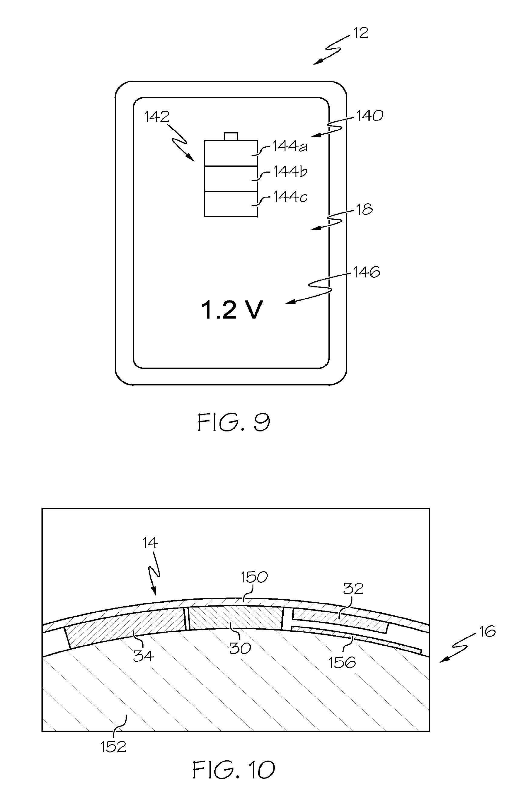
FIG. 10 is a diagrammatic detail view of the battery of FIG. 1.
The embodiments set forth in the drawings are illustrative in nature and not intended to be limiting of the invention defined by the claims. Moreover, individual features of the drawings and invention will be more fully apparent and understood in view of the detailed description.
DETAILED DESCRIPTION OF THE INVENTION
The following text sets forth a broad description of numerous different embodiments. The description is to be construed as exemplary only and does not describe every possible embodiment since describing every possible embodiment would be impractical, if not impossible, and it will be understood that any feature, characteristic, component, composition, ingredient, product, step or methodology described herein can be deleted, combined with or substituted for, in whole or part, any other feature, characteristic, component, composition, ingredient, product, step or methodology described herein. Numerous alternative embodiments could be implemented, using either current technology or technology developed after the filing date of this patent, which would still fall within the scope of the claims.
It should also be understood that, unless a term is expressly defined in this specification using the sentence "As used herein, the term `.sub.------------` is hereby defined to mean . . . " or a similar sentence, there is no intent to limit the meaning of that term, either expressly or by implication, beyond its plain or ordinary meaning, and such term should not be interpreted to be limited in scope based on any statement made in any section of this patent (other than the language of the claims). No term is intended to be essential unless so stated. To the extent that any term recited in the claims at the end of this patent is referred to in this patent in a manner consistent with a single meaning, that is done for sake of clarity only so as to not to confuse the reader, and it is not intended that such a claim term be limited, by implication or otherwise, to that single meaning. Finally, unless a claim element is defined by reciting the word "means" and a function without the recital of any structure, it is not intended that the scope of any claim element be interpreted based on the application of 35 U.S.C. .sctn. 112, sixth paragraph.
Embodiments described herein generally relate to systems and methods for remote sensing of remaining battery capacity using on-battery circuitry. The systems and methods utilize on-battery circuitry that provides a signal indicative of remaining battery capacity to a handheld computing device remote from the battery. As used herein, the term "indicative of remaining battery capacity" can mean any signal or measured value such as a battery voltage that can be used to estimate battery capacity. The handheld computing device can receive the signal and use the signal to provide remaining battery capacity information to a user, for example, using a display. The remaining battery capacity information may be an actual voltage measurement and/or a charge amount (e.g., based on a voltage measurement or calculation).
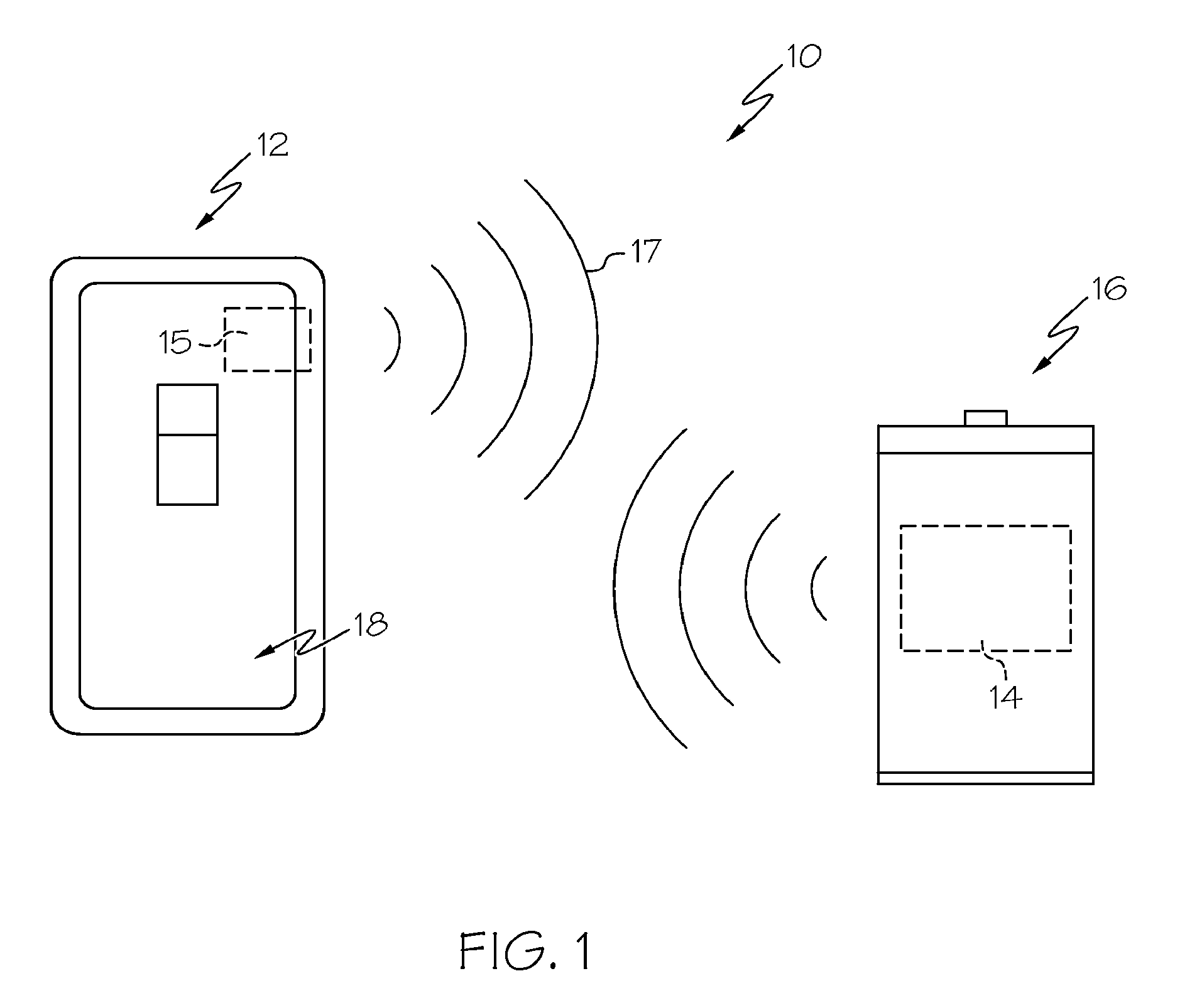
Referring to FIG. 1, a remote sensing system 10 includes a handheld computing device 12 comprising a reader system 15 capable of communicating remotely with a remote charge indicator system 14 that is carried by and operatively connected to a power source, such as a battery 16. The handheld computing device 12 can use the reader system 15 to excite the remote charge indicator system 14 by transmitting an interrogation signal 17, such as a radio frequency (RF) pulse. As will be described below, the handheld computing device 12 remotely determines a time period to charge (or discharge) a capacitor of a resistor-capacitor (RC) circuit to a predetermined voltage. The RC circuit is part of the remote charge indicator system 14 and is located on the battery 16. The time period can be used by the handheld computing device 12 to determine charge information indicative of remaining battery capacity, which can be displayed on a display device 18 and viewed by a user.
The reader system 15 may be part of any suitable handheld computing device 12 such as a cellular phone or other computing device. The display device 18 may be any suitable display device used in a portable, handheld electronic device, such as, for example, LCD display devices, LED display devices, OLED display devices, and other types of display devices which may be heretofore developed. Further, display device 18 may be any other variety of indicators, including, but not limited to a series of lights and/or other types of light devices as opposed to a single integrated display screen. The display device 18 may include an electronic paper component such as an electrophoretic display, which may be an information display that forms visible images by rearranging charged pigment particles using an electric field. The display device 18 may be used for electronically displaying graphics, text, and other elements to a user. In some embodiments, the display device 18 may be a touch-screen user interface that is used with the tip of a finger of the user and/or a stylus or other touching device to select elements from the screen, to draw figures, and to enter text with a character recognition program running on the device. In some embodiments, the device may also include other types of output devices such as for example, sound devices, vibration devices, etc.
FIG. 2 illustrates schematically the remote sensing system 10 including the handheld computing device 12 and the remote charge indicator system 14. The handheld computing device 12 may include a processor 20, memory 22, communications module 24 including an antenna 26 as part of the reader system 15, a user interface 28 and the display device 18. In some embodiments, the handheld computing device 12 may include additional communications modules for communicating with other computers and networks. The processor 20 may run software, such as reader applications saved in the memory 22 that allow the user to control operation of the communications module 24 (e.g., send a user-initiated RF interrogation signal) and other features of the handheld computing device. Logic may also be included that allows the processor to determine the remaining battery capacity information and display the information using the display device 18.
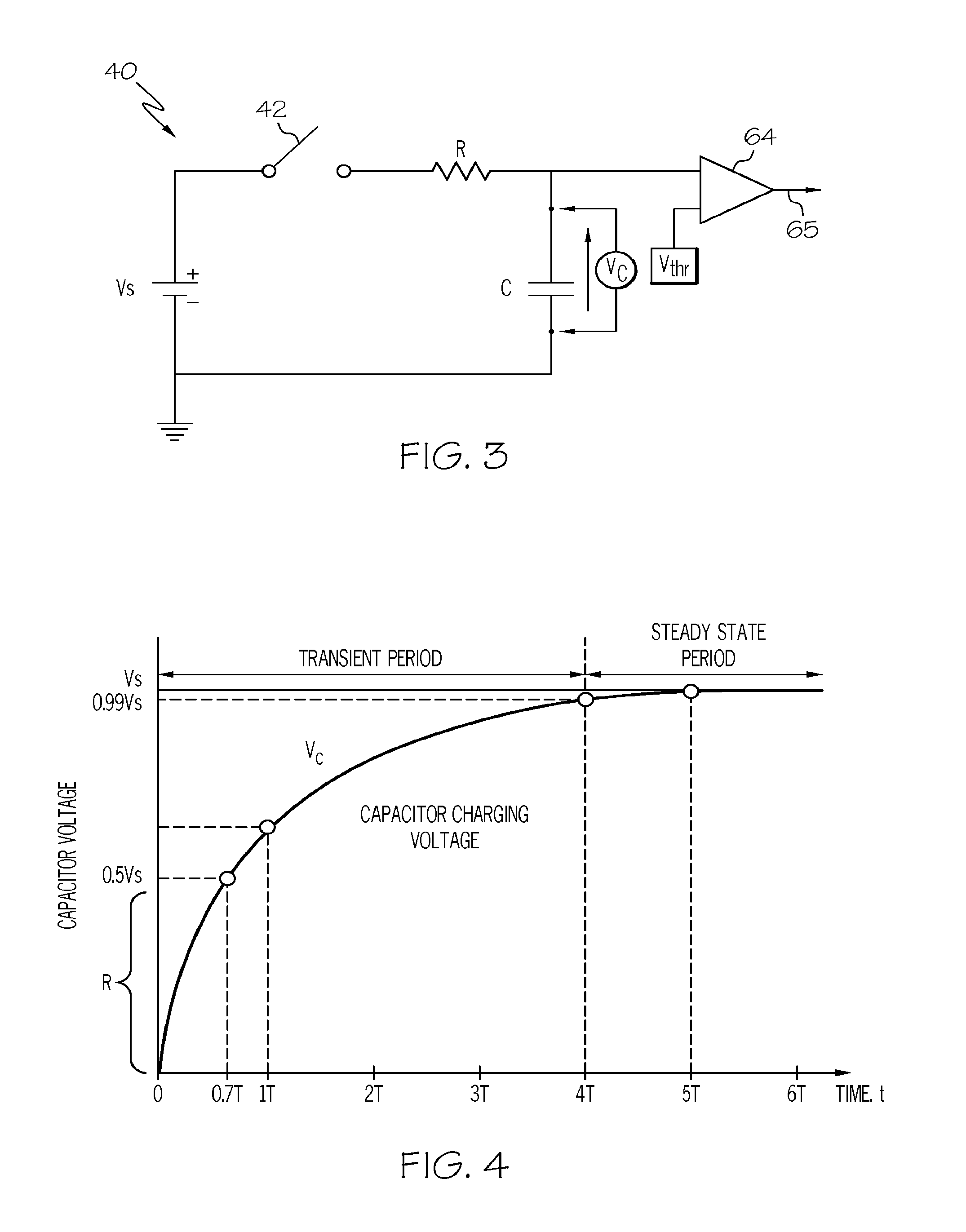
The remote charge indicator system 14 may be located on the battery 16 and includes a communications module 30 including an antenna 32 (e.g., an RFID tag) and a voltage sensing module 34 operatively connected to the battery 16. The communications module 30 may include any suitable communications circuitry such as RFID and near field communication (NFC) circuitry and may utilize any suitable frequency bands such as high frequency (HF) 13.56 MHz, ultra-high frequency (UHF) (860-956 MHz) or microwave frequency (2.4-5.8 GHz). Other communications may be used, such as infrared (IR) and ultrasound. The communications module 30 may be powered by the battery 16 (active), may be only partially powered by the battery 16 (semi-active or battery assisted passive) or may not be powered by the battery 16 (passive). The voltage sensing module 34 can be configured to provide an output signal that is proportional to battery voltage, rather than outputting the battery voltage itself. Referring to FIG. 3, a resistor-capacitor (RC) circuit 40 including a resistor R and a capacitor C may be used as part of the voltage sensing module 34 to provide an output signal (capacitor voltage) that is proportional to the battery voltage. A switch 42 (e.g., a transistor) may be used to control charging of the capacitor C. FIG. 3 illustrates the exemplary RC circuit 40 where the charging voltage of the capacitor C is given by:
##EQU00001##
where: V.sub.c is the capacitor voltage; V.sub.s is the battery voltage; R is the resistance of the resistor; and C is the capacitance of the capacitor.
The time for the capacitor voltage to reach a pre-determined threshold voltage V.sub.thr is given by:
.times..times. ##EQU00002##
Thus, knowing the time t, threshold voltage V.sub.thr, resistance R and capacitance C, the battery voltage V.sub.s can be calculated. This calculated battery voltage can be correlated to the remaining battery capacity (i.e., battery charge). Referring to FIG. 4, the relation between the charging time of the capacitor C and the battery voltage V.sub.s is exponential. A threshold capacitor voltage V.sub.thr can be chosen to be in the quasi-linear region R of the capacitor charging voltage curve (e.g., within less than about or 40 percent of battery voltage V.sub.s), which can facilitate the determination of the remaining battery capacity information. In some embodiments, the processor 20 may have access to tables saved in memory 22 that can be used to convert the time to a battery voltage V.sub.s for determining the remaining battery capacity information.
Referring now to FIG. 5, a method 50 of remote sensing remaining battery capacity is illustrated. At step 52, a user selects a battery scanning application on their handheld computing device 12, such as a cellular phone or tablet computer. At step 54, the user places the handheld computing device 12 in close proximity to the battery 16 (e.g., within about a foot or less, such as within about 6 inches or less, such as within about an inch or less, such as touching the battery 16). The distance the handheld computing device 12 is to be placed from the battery 16 and the remote charge indicator system 12 can depend, at least in part, on the communications circuitry used. A battery scanning operation is initiated at step 56 using the user interface 28 (FIG. 2). Alternatively, a battery scanning operation may be initiated automatically (e.g., using a periodic scanning setting). At step 58, the communications module 24 of the reader system 15, in response to the user input or automatically sensing battery presence, can interrogate the communications module 30 of the remote charge indicator system 14. At step 60, the switch 42 of the RC circuit 40 (FIG. 3) is closed and the battery charges the capacitor C. At step 62, a comparator 64 (FIG. 3) compares the increasing voltage of the capacitor C to the predetermined threshold voltage. When the capacitor voltage reaches the predetermined threshold voltage, the comparator 64 sends a signal 65 to the communications module 30 of the remote charge indicator system 14 at step 66. At step 68, the communications module 30 of the remote charge indicator system 14 may send a response signal (e.g., an RF response signal) to the communications module 24 of the handheld computing device 12. At step 70, the processor 20 determines a time period between the time the communications module 30 is interrogated at step 58 and the time the response signal is received at step 68. The time period is used to determine the remaining battery capacity and the remaining battery capacity information at step 72. In some embodiments, the remaining battery capacity information may be displayed on the display device 18 at step 74. The remaining battery capacity information can provide an indication to the user of the battery capacity remaining. In some embodiments, the remaining battery capacity information may include the battery voltage and/or the device remaining runtime in different modes.
While the above embodiments utilize time from interrogation to receipt of the response signal to determine battery voltage and provide the remaining battery capacity information, other configurations are possible. As another example, the difference in charging time of multiple RC circuits with different time constants may be used. Referring to FIG. 6, a resistor-capacitor (RC) circuit 100 including resistor R.sub.1 and capacitor C.sub.1 as part of a first RC circuit portion 103 and resistor R.sub.2 and capacitor C.sub.2 as part of a second RC circuit portion 105 may be used as part of the voltage sensing module 34 to provide an output signal (capacitor voltage) that is proportional to the battery voltage. A switch 102 (e.g., a transistor) may be used to control charging of the capacitors C.sub.1 and C.sub.2. FIG. 6 illustrates the exemplary RC circuit 100 where the difference in the charging time of the two capacitors C.sub.1 and C.sub.2 with different time constants from the same battery voltage to charge to the same threshold voltage given by:
.times..times..times..times. ##EQU00003##
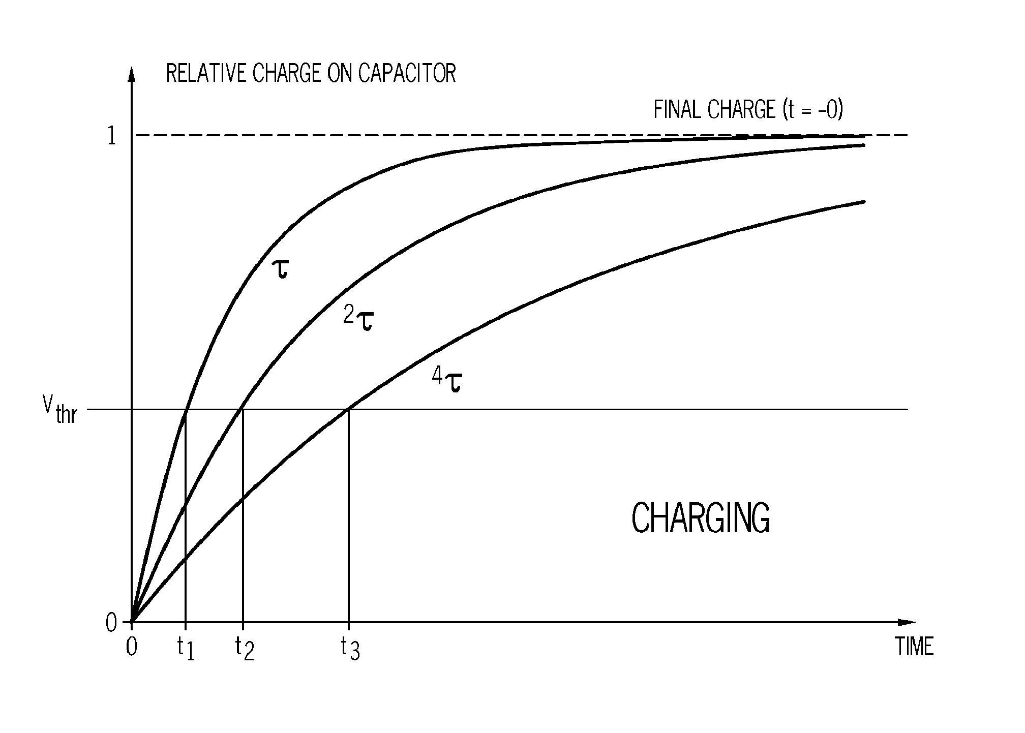
Thus, knowing the times t.sub.1, t.sub.2, resistances R.sub.1, R.sub.2, threshold voltage V.sub.thr and capacitances C.sub.1, C.sub.2, the battery voltage V.sub.s can be calculated. This calculated battery voltage can be correlated to the remaining battery capacity. Referring to FIG. 7, capacitor voltage curves are illustrated for three capacitors each being part of RC circuits having different time constants .tau.. The relation between the charging time of the capacitors C.sub.1 and C.sub.2 (and C.sub.3) and the battery voltage V.sub.s is exponential. Measuring the time difference between two response signals can eliminate the need to utilize the time of interrogation.
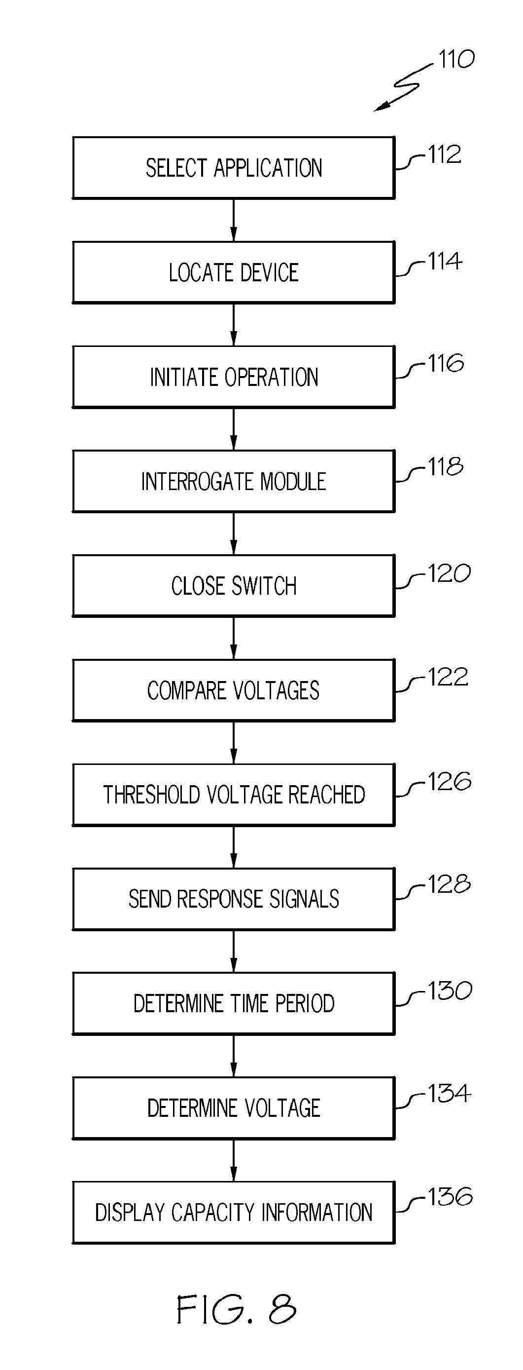
Referring to FIG. 8, another method 110 of remote sensing remaining battery capacity is illustrated. At step 112, a user selects a battery scanning application on their handheld computing device 12, such as a cellular phone or tablet computer. At step 114, the user places the handheld computing device 12 in close proximity to the battery 16. A battery scanning operation is initiated at step 116 using the user interface 28 (FIG. 2) or automatically by periodic scanning. Alternatively, a battery scanning operation may be initiated automatically. At step 118, the communications module 24 of the reader system 15, in response to the user input, can interrogate the communications module 30 of the remote charge indicator system 14. At step 120, the switch 102 of the RC circuit 100 (FIG. 6) is closed and the battery charges the capacitors C.sub.1 and C.sub.2. At step 122, a comparator 124 and 125 (FIG. 6) compares the increasing voltages of the capacitors C.sub.1 and C.sub.2 to the same predetermined threshold voltage. When the capacitor voltages reach the predetermined threshold voltage, the comparator 124 and 125 sends a first signal (associated with the capacitor C.sub.1) and a second signal (associated with the capacitor C.sub.2) to a logic module 127 at step 126, which can provide a pulse having a duration that corresponds to a time period between the first and second signals. At step 128, the communications module 30 of the remote charge indicator system 14 may send the pulse to the communications module 24 of the handheld computing device 12. At step 130, the processor 20 determines a time period of the pulse or between the first and second response signals. The time period is used to determine remaining battery capacity information at step 134. In some embodiments, the remaining battery capacity information may be displayed on the display device 18 at step 136. The remaining battery capacity information can provide an indication to the user of the battery capacity remaining. In some embodiments, the remaining battery capacity information may include the battery voltage.
Referring to FIG. 9, the handheld computing device 12 is illustrated showing the display device 18. The remaining battery capacity information 140 may be displayed to the user in the form of graphic indicia 142. The graphic indicia 142 may be an image of a battery level indicator that includes charge level bars 144a, 144b and 144c that are used to indicate the battery capacity remaining. As one example, for a 1.5V AA size alkaline battery, a calculated voltage of above a first predetermined voltage (e.g., about 1.45V) may result in the processor 20 displaying about a full battery capacity of all three charge level bars 144a, 144b and 144c. For a calculated voltage of between the first predetermined voltage and a second predetermined lower voltage (e.g., between about 1.35V and about 1.45V), the processor 20 may display only two of the charge level bars 144b and 144c indicating a charge level below a certain percentage. In instances where the processor calculates a battery voltage of between the second predetermined voltage and a third predetermined lower voltage (e.g., between about 1.25V and about 1.35V), only one charge level bar 144c may be displayed. As another example, for a 1.5V AA size nickel-metal hydride battery, a calculated voltage of above a first predetermined voltage (e.g., about 1.35V) may result in the processor 20 displaying about a full battery capacity of all three charge level bars 144a, 144b and 144c. For a calculated voltage of between the first predetermined voltage and a second predetermined lower voltage (e.g., between about 1.25V and about 1.35V), the processor 20 may display only two of the charge level bars 144b and 144c indicating a charge level below a certain percentage. In instances where the processor calculates a battery voltage of between the second predetermined voltage and a third predetermined lower voltage (e.g., between about 1.2V and about 1.25V), only one charge level bar 144c may be displayed. Should the processor 20 calculate a battery voltage less than the third predetermined voltage, none of the charge level bars may be displayed. Any suitable display arrangement can be utilized including more or less than three charge level bars. The graphic indicia 142 may also change colors, depending on the calculated charge level. The remaining battery capacity information 140 being displayed may include a numerical voltage value 146.
Referring now to FIG. 10, the battery 16 is illustrated and includes a label layer 150 and a battery housing 152 about which the label layer 150 is applied. The remote charger indicator system 14 including the communications module 30, the antenna 32 and the voltage sensing module 30 are located between the label layer 150 and the battery housing 152. In some embodiments, the communications module 30 (e.g., an RFID tag), antenna 32 and the voltage sensing module 34 (the RC circuit) may all be part of an integrated circuit (IC). In some embodiments, the label layer 150, itself, may include a silicon IC. A thin (e.g., less than about 200 micrometers) magnetic diverter 156 formed of ferrite materials can be placed between the antenna 32 and the battery housing 152 to inhibit interference with the antenna 32. Any suitable battery may be used, such as alkaline, nickel-metal hydride, lithium, etc. The battery may be rechargeable or non-rechargeable.
In some embodiments, the communications module 30 may include memory that stores unique identification information. The identification information may be provided to the handheld computing device 12 when the communications module 30 sends the response signal. The handheld computing device 12 may use the identification information to distinguish between multiple batteries being tested simultaneously. For example, in one embodiment, a series of batteries may be tested and the remaining battery capacity information for the lowest voltage battery (i.e., the weakest link) may be displayed. As another embodiment, a device using the batteries may include a voltage sensing module, which can be used to determine a total remaining battery capacity for all batteries in the device. The voltage sensing module may be located, for example, in a battery compartment and connected to a device power input. The remaining battery capacity information may not only include remaining battery capacity, but may also include usage information, such as remaining photos, play time, talk time, etc.
The above-described remote sensing systems provide an electronic circuit on a battery for remote sensing of battery voltage and determining remaining battery capacity information. The remote sensing systems utilize a distributed analog to digital conversion where the processor used for calculating the battery voltage and determining the remaining battery capacity information is located in the handheld computing device, and not on the battery, leaving a minimum of components on the battery. While battery testing is described primarily above, the testing systems can be applied to any type of remote sensing systems where a voltage measurement is required and is not limited to battery monitoring. The remote sensing systems can be applied to any of disposable or rechargeable cells of any size (e.g., AAAA, AAA, AA, C, D, 9V) and to special sizes for specific applications (e.g., coin, button, prismatic). The remote sensing systems can be applied to prismatic or round rechargeable Lithium Ion cells in cases where a device does not include a fuel gauge or the device has replaceable batteries to that the status of a replacement battery can be determined remotely. The remote sensing systems can be applied to any portable or battery powered device, monitoring total battery voltage in the device rather than individual cell voltages. The above remote charge indicator systems can also operate by discharging the capacitors. For example, the capacitors can always be placed in parallel with the battery and equalized with the battery voltage. Upon interrogating the communications module, the capacitor may be disconnected from the battery and discharge through the resistor down to a predetermined threshold voltage. That time difference is a function of battery voltage and can be used to calculate the battery voltage and remaining battery capacity.
The dimensions and values disclosed herein are not to be understood as being strictly limited to the exact numerical values recited. Instead, unless otherwise specified, each such dimension is intended to mean both the recited value and a functionally equivalent range surrounding that value. For example, a dimension disclosed as "40 mm" is intended to mean "about 40 mm."
Every document cited herein, including any cross referenced or related patent or application, is hereby incorporated herein by reference in its entirety unless expressly excluded or otherwise limited. The citation of any document is not an admission that it is prior art with respect to any invention disclosed or claimed herein or that it alone, or in any combination with any other reference or references, teaches, suggests or discloses any such invention. Further, to the extent that any meaning or definition of a term in this document conflicts with any meaning or definition of the same term in a document incorporated by reference, the meaning or definition assigned to that term in this document shall govern.
While particular embodiments of the present invention have been illustrated and described, it would be obvious to those skilled in the art that various other changes and modifications can be made. It is therefore intended to cover in the appended claims all such changes and modifications.
* * * * *
References
D00000
D00001
D00002
D00003
D00004
D00005
D00006
D00007
M00001
M00002
M00003
XML
uspto.report is an independent third-party trademark research tool that is not affiliated, endorsed, or sponsored by the United States Patent and Trademark Office (USPTO) or any other governmental organization. The information provided by uspto.report is based on publicly available data at the time of writing and is intended for informational purposes only.
While we strive to provide accurate and up-to-date information, we do not guarantee the accuracy, completeness, reliability, or suitability of the information displayed on this site. The use of this site is at your own risk. Any reliance you place on such information is therefore strictly at your own risk.
All official trademark data, including owner information, should be verified by visiting the official USPTO website at www.uspto.gov. This site is not intended to replace professional legal advice and should not be used as a substitute for consulting with a legal professional who is knowledgeable about trademark law.