Spinal implant with porous and solid surfaces
Willis , et al. Ja
U.S. patent number 10,182,923 [Application Number 14/994,749] was granted by the patent office on 2019-01-22 for spinal implant with porous and solid surfaces. This patent grant is currently assigned to Stryker European Holdings I, LLC. The grantee listed for this patent is Stryker European Holdings I, LLC. Invention is credited to Chau Ngo, Robin Stamp, Steven Willis, Justyna Zielinska.


View All Diagrams
| United States Patent | 10,182,923 |
| Willis , et al. | January 22, 2019 |
Spinal implant with porous and solid surfaces
Abstract
A spinal implant including porous and solid portions is disclosed. The implant includes porous portions on upper and lower surfaces and in an interior thereof. Methods of manufacturing and implanting such implants are also disclosed.
| Inventors: | Willis; Steven (Mahwah, NJ), Zielinska; Justyna (Linden, NJ), Stamp; Robin (Montclair, NJ), Ngo; Chau (Secaucus, NJ) | ||||||||||
|---|---|---|---|---|---|---|---|---|---|---|---|
| Applicant: |
|
||||||||||
| Assignee: | Stryker European Holdings I,
LLC (Kalamazoo, MI) |
||||||||||
| Family ID: | 55129796 | ||||||||||
| Appl. No.: | 14/994,749 | ||||||||||
| Filed: | January 13, 2016 |
Prior Publication Data
| Document Identifier | Publication Date | |
|---|---|---|
| US 20160199193 A1 | Jul 14, 2016 | |
Related U.S. Patent Documents
| Application Number | Filing Date | Patent Number | Issue Date | ||
|---|---|---|---|---|---|
| 62103276 | Jan 14, 2015 | ||||
| Current U.S. Class: | 1/1 |
| Current CPC Class: | A61F 2/44 (20130101); B22F 5/10 (20130101); B33Y 80/00 (20141201); A61F 2/447 (20130101); B22F 7/002 (20130101); A61F 2/4455 (20130101); B22F 3/1055 (20130101); B22F 3/24 (20130101); A61F 2/3094 (20130101); A61F 2002/30011 (20130101); A61F 2002/30904 (20130101); B22F 2003/247 (20130101); A61F 2002/30784 (20130101); B33Y 10/00 (20141201); A61F 2002/3092 (20130101); A61F 2/4611 (20130101); A61F 2002/30962 (20130101); A61F 2002/3093 (20130101); A61F 2002/30985 (20130101); B22F 7/08 (20130101); B22F 2005/005 (20130101); C22C 1/0458 (20130101); A61F 2002/30772 (20130101); A61F 2002/30593 (20130101) |
| Current International Class: | A61F 2/44 (20060101); A61F 2/30 (20060101); A61F 2/46 (20060101) |
References Cited [Referenced By]
U.S. Patent Documents
| 3486505 | December 1969 | Morrison |
| 3641590 | February 1972 | Michele |
| 3852045 | December 1974 | Wheeler et al. |
| 3855638 | December 1974 | Pilliar |
| 4047524 | September 1977 | Hall |
| 4501269 | February 1985 | Bagby |
| 4612160 | September 1986 | Donlevy et al. |
| 4653489 | March 1987 | Tronzo |
| 4681589 | July 1987 | Tronzo |
| 4718914 | January 1988 | Frey |
| 4743262 | May 1988 | Tronzo |
| 4820305 | April 1989 | Harms et al. |
| 4834757 | May 1989 | Brantigan |
| 4946378 | August 1990 | Hirayama et al. |
| 5071437 | December 1991 | Steffee |
| 5156628 | October 1992 | Kranz |
| 5192327 | March 1993 | Brantigan |
| 5263986 | November 1993 | Noiles et al. |
| 5306309 | April 1994 | Wagner et al. |
| 5314477 | May 1994 | Marnay |
| 5370692 | December 1994 | Fink et al. |
| 5431658 | July 1995 | Moskovich |
| 5443514 | August 1995 | Steffee |
| 5443515 | August 1995 | Cohen et al. |
| 5458643 | October 1995 | Oka et al. |
| 5504300 | April 1996 | Devanathan et al. |
| 5507816 | April 1996 | Bullivant |
| 5514180 | May 1996 | Heggeness et al. |
| 5609635 | March 1997 | Michelson |
| 5672284 | September 1997 | Devanathan et al. |
| 5683394 | November 1997 | Rinner |
| 5702449 | December 1997 | McKay |
| 5702455 | December 1997 | Saggar |
| 5709683 | January 1998 | Bagby |
| 5713899 | February 1998 | Marnay et al. |
| 5723011 | March 1998 | Devanathan et al. |
| 5734959 | March 1998 | Krebs et al. |
| 5768134 | June 1998 | Swaelens et al. |
| 5885299 | March 1999 | Winslow et al. |
| 5893889 | April 1999 | Harrington |
| 5961554 | October 1999 | Janson et al. |
| 6039762 | March 2000 | McKay |
| 6096080 | August 2000 | Nicholson et al. |
| 6113638 | September 2000 | Williams et al. |
| 6120503 | September 2000 | Michelson |
| 6206924 | March 2001 | Timm |
| 6235059 | May 2001 | Benezech et al. |
| 6241769 | June 2001 | Nicholson et al. |
| 6241771 | June 2001 | Gresser et al. |
| 6325805 | December 2001 | Ogilvie et al. |
| 6336928 | January 2002 | Guerin et al. |
| 6364880 | April 2002 | Michelson |
| 6432107 | August 2002 | Ferree |
| 6447524 | September 2002 | Knodel et al. |
| 6447546 | September 2002 | Bramlet et al. |
| 6458158 | October 2002 | Anderson et al. |
| 6471725 | October 2002 | Ralph et al. |
| 6485521 | November 2002 | Say et al. |
| 6533818 | March 2003 | Weber et al. |
| 6569201 | May 2003 | Moumene et al. |
| 6572654 | June 2003 | Santilli |
| 6582468 | June 2003 | Gauchet |
| 6623525 | September 2003 | Ralph et al. |
| 6673075 | January 2004 | Santilli |
| 6679887 | January 2004 | Nicholson et al. |
| 6716245 | April 2004 | Pasquet et al. |
| 6726720 | April 2004 | Ross et al. |
| 6740118 | May 2004 | Eisermann et al. |
| 6740186 | May 2004 | Hawkins et al. |
| 6743256 | June 2004 | Mason |
| 6767367 | July 2004 | Michelson |
| 6790233 | September 2004 | Brodke et al. |
| 6800093 | October 2004 | Nicholson et al. |
| 6843805 | January 2005 | Webb et al. |
| 6863689 | March 2005 | Ralph et al. |
| 6945448 | September 2005 | Medlin et al. |
| 6970233 | November 2005 | Blatchford |
| 7048766 | May 2006 | Ferree |
| 7056344 | June 2006 | Ruppert et al. |
| 7056345 | June 2006 | Kuslich |
| 7060097 | June 2006 | Fraser et al. |
| 7128761 | October 2006 | Kuras et al. |
| 7135042 | November 2006 | Stoll |
| 7204852 | April 2007 | Marnay et al. |
| 7235101 | June 2007 | Berry et al. |
| 7238203 | July 2007 | Bagga et al. |
| 7241313 | July 2007 | Unwin et al. |
| 7255713 | August 2007 | Malek |
| 7320707 | January 2008 | Zucherman et al. |
| 7331995 | February 2008 | Eisermann et al. |
| 7364589 | April 2008 | Eisermann |
| 7497876 | March 2009 | Tuke et al. |
| 7501073 | March 2009 | Wen et al. |
| 7503934 | March 2009 | Eisermann et al. |
| 7503935 | March 2009 | Zucherman et al. |
| 7537664 | May 2009 | O'Neill et al. |
| 7563284 | July 2009 | Coppes et al. |
| 7588600 | September 2009 | Benzel et al. |
| 7594931 | September 2009 | Louis et al. |
| 7611538 | November 2009 | Belliard et al. |
| 7635447 | December 2009 | Hamman et al. |
| 7658766 | February 2010 | Melkent et al. |
| 7662186 | February 2010 | Bagga et al. |
| 7670375 | March 2010 | Schaller |
| 7695516 | April 2010 | Zeegers |
| 7749271 | July 2010 | Fischer et al. |
| 7763076 | July 2010 | Navarro et al. |
| 7842088 | November 2010 | Rashbaum et al. |
| 7883661 | February 2011 | Hamman et al. |
| 7896919 | March 2011 | Belliard et al. |
| 7918382 | April 2011 | Charlebois et al. |
| 7922765 | April 2011 | Reiley |
| 8021403 | September 2011 | Wall et al. |
| 8034076 | October 2011 | Criscuolo et al. |
| 8100974 | January 2012 | Duggal et al. |
| 8147861 | April 2012 | Jones et al. |
| 8191760 | June 2012 | Charlebois et al. |
| 8202305 | June 2012 | Reiley |
| 8231676 | July 2012 | Trudeau et al. |
| 8262737 | September 2012 | Bagga et al. |
| 8266780 | September 2012 | Bollinger et al. |
| 8268100 | September 2012 | O'Neill et al. |
| 8303879 | November 2012 | Bertele et al. |
| 8343224 | January 2013 | Lynn et al. |
| 8349015 | January 2013 | Bae et al. |
| 8361150 | January 2013 | Zhang et al. |
| 8361153 | January 2013 | Ralph et al. |
| 8361380 | January 2013 | Hamman et al. |
| 8388667 | March 2013 | Reiley et al. |
| 8403991 | March 2013 | Ullrich, Jr. et al. |
| 8414648 | April 2013 | Reiley |
| 8414650 | April 2013 | Bertele et al. |
| 8414654 | April 2013 | Ganey |
| 8414820 | April 2013 | Bertele et al. |
| 8425570 | April 2013 | Reiley |
| 8425604 | April 2013 | Trieu |
| 8430930 | April 2013 | Hunt |
| 8435301 | May 2013 | Gerber et al. |
| 8435302 | May 2013 | Ulrich, Jr. et al. |
| 8444693 | May 2013 | Reiley |
| 8470004 | June 2013 | Reiley |
| 8470042 | June 2013 | Zhang et al. |
| 8480749 | July 2013 | Ullrich, Jr. et al. |
| 8496710 | July 2013 | Bagga et al. |
| 8530560 | September 2013 | Kerr et al. |
| 8545568 | October 2013 | Ulrich, Jr. et al. |
| 8551173 | October 2013 | Lechmann et al. |
| 8551176 | October 2013 | Ullrich, Jr. et al. |
| 8556981 | October 2013 | Jones et al. |
| 8562684 | October 2013 | Ullrich, Jr. et al. |
| 8562685 | October 2013 | Ullrich, Jr. et al. |
| 8585765 | November 2013 | Ullrich, Jr. et al. |
| 8585766 | November 2013 | Ullrich, Jr. et al. |
| 8585767 | November 2013 | Ullrich, Jr. et al. |
| 8591590 | November 2013 | Ullrich, Jr. et al. |
| 8617248 | December 2013 | Ullrich, Jr. et al. |
| 8632604 | January 2014 | Brooks |
| 8673016 | March 2014 | Liu |
| 8734462 | May 2014 | Reiley et al. |
| 8747412 | June 2014 | Bae et al. |
| 8758442 | June 2014 | Ullrich, Jr. et al. |
| 8758443 | June 2014 | Ullrich, Jr. et al. |
| 8814939 | August 2014 | Ullrich, Jr. et al. |
| 8814978 | August 2014 | Hamman et al. |
| 8827986 | September 2014 | Shachar et al. |
| 8834571 | September 2014 | Bagga et al. |
| 8840623 | September 2014 | Reiley |
| 8845736 | September 2014 | Zhang et al. |
| 8864831 | October 2014 | Lee et al. |
| 8906093 | December 2014 | Malone |
| 8906095 | December 2014 | Christensen et al. |
| 8940053 | January 2015 | Ullrich, Jr. et al. |
| 8979934 | March 2015 | Kirschman |
| 8985430 | March 2015 | Charlebois et al. |
| 8992619 | March 2015 | Patterson et al. |
| 9089428 | July 2015 | Bertele et al. |
| 9135374 | September 2015 | Jones et al. |
| 9180010 | November 2015 | Dong et al. |
| 2002/0004683 | January 2002 | Michelson |
| 2002/0035400 | March 2002 | Bryan et al. |
| 2002/0165613 | November 2002 | Lin et al. |
| 2003/0045940 | March 2003 | Eberlein et al. |
| 2003/0055505 | March 2003 | Sicotte et al. |
| 2003/0195517 | October 2003 | Michelson |
| 2003/0195632 | October 2003 | Foley et al. |
| 2004/0059318 | March 2004 | Zhang et al. |
| 2004/0117022 | June 2004 | Marnay et al. |
| 2004/0133279 | July 2004 | Krueger et al. |
| 2004/0148028 | July 2004 | Ferree et al. |
| 2004/0176853 | September 2004 | Sennett et al. |
| 2004/0193271 | September 2004 | Fraser et al. |
| 2004/0199254 | October 2004 | Louis et al. |
| 2004/0220668 | November 2004 | Eisermann et al. |
| 2004/0220670 | November 2004 | Eisermann et al. |
| 2004/0230307 | November 2004 | Eisermann |
| 2004/0260286 | December 2004 | Ferree |
| 2005/0004672 | January 2005 | Pafford et al. |
| 2005/0033435 | February 2005 | Belliard et al. |
| 2005/0043802 | February 2005 | Eisermann et al. |
| 2005/0060034 | March 2005 | Berry et al. |
| 2005/0123672 | June 2005 | Justin et al. |
| 2005/0149192 | July 2005 | Zucherman et al. |
| 2005/0149193 | July 2005 | Zucherman et al. |
| 2005/0165408 | July 2005 | Puno et al. |
| 2005/0177238 | August 2005 | Khandkar et al. |
| 2005/0192586 | September 2005 | Zucherman et al. |
| 2006/0004453 | January 2006 | Bartish et al. |
| 2006/0085071 | April 2006 | Lechmann et al. |
| 2006/0089656 | April 2006 | Allard et al. |
| 2006/0116769 | June 2006 | Marnay et al. |
| 2006/0129238 | June 2006 | Paltzer |
| 2006/0136063 | June 2006 | Zeegers |
| 2006/0147332 | July 2006 | Jones et al. |
| 2006/0178745 | August 2006 | Bartish et al. |
| 2006/0212121 | September 2006 | Ferree |
| 2007/0050032 | March 2007 | Gittings et al. |
| 2007/0050033 | March 2007 | Reo et al. |
| 2007/0055378 | March 2007 | Ankney et al. |
| 2007/0073404 | March 2007 | Rashbaum et al. |
| 2007/0118145 | May 2007 | Fischer et al. |
| 2007/0142914 | June 2007 | Jones et al. |
| 2007/0173940 | July 2007 | Hestad et al. |
| 2007/0233244 | October 2007 | Lopez et al. |
| 2007/0233261 | October 2007 | Lopez et al. |
| 2007/0239278 | October 2007 | Heinz |
| 2007/0270968 | November 2007 | Baynham et al. |
| 2008/0004709 | January 2008 | O'Neill et al. |
| 2008/0015702 | January 2008 | Lakin et al. |
| 2008/0051901 | February 2008 | de Villiers et al. |
| 2008/0051902 | February 2008 | Dwyer |
| 2008/0097435 | April 2008 | DeRidder et al. |
| 2008/0109005 | May 2008 | Trudeau et al. |
| 2008/0154377 | June 2008 | Voellmicke |
| 2008/0161927 | July 2008 | Savage |
| 2008/0183292 | July 2008 | Trieu |
| 2008/0249575 | October 2008 | Waugh et al. |
| 2008/0262623 | October 2008 | Bagga et al. |
| 2008/0269756 | October 2008 | Tomko et al. |
| 2008/0306595 | December 2008 | McLeod et al. |
| 2009/0005870 | January 2009 | Hawkins et al. |
| 2009/0088849 | April 2009 | Armstrong et al. |
| 2009/0093885 | April 2009 | Levieux et al. |
| 2009/0112323 | April 2009 | Hestad et al. |
| 2009/0138015 | May 2009 | Conner et al. |
| 2009/0164020 | June 2009 | Janowski et al. |
| 2009/0240333 | September 2009 | Trudeau et al. |
| 2010/0004747 | January 2010 | Lin |
| 2010/0042218 | February 2010 | Nebosky et al. |
| 2010/0042221 | February 2010 | Boyd |
| 2010/0076559 | March 2010 | Bagga et al. |
| 2010/0094426 | April 2010 | Grohowski, Jr. et al. |
| 2010/0137990 | June 2010 | Apatsidis et al. |
| 2010/0185292 | July 2010 | Hochschuler et al. |
| 2010/0211119 | August 2010 | Refai et al. |
| 2010/0222750 | September 2010 | Cheng |
| 2010/0256773 | October 2010 | Thijs et al. |
| 2010/0262244 | October 2010 | Savage-Erickson et al. |
| 2010/0268343 | October 2010 | Dewey et al. |
| 2011/0004307 | January 2011 | Ahn et al. |
| 2011/0029081 | February 2011 | Malone |
| 2011/0071635 | March 2011 | Zhang et al. |
| 2011/0092948 | April 2011 | Shachar et al. |
| 2011/0160866 | June 2011 | Laurence et al. |
| 2011/0196494 | August 2011 | Yedlicka et al. |
| 2011/0196495 | August 2011 | Hunt |
| 2011/0282392 | November 2011 | Murphy et al. |
| 2011/0282454 | November 2011 | Ullrich, Jr. et al. |
| 2011/0313532 | December 2011 | Hunt |
| 2012/0078373 | March 2012 | Gamache et al. |
| 2012/0253406 | October 2012 | Bae et al. |
| 2012/0265306 | October 2012 | Trieu |
| 2012/0277876 | November 2012 | Ullrich, Jr. et al. |
| 2012/0303127 | November 2012 | Ullrich, Jr. et al. |
| 2012/0312778 | December 2012 | Ullrich, Jr. et al. |
| 2012/0312779 | December 2012 | Patterson et al. |
| 2012/0330420 | December 2012 | Brodke et al. |
| 2013/0030529 | January 2013 | Hunt |
| 2013/0123925 | May 2013 | Patterson et al. |
| 2013/0123935 | May 2013 | Hunt et al. |
| 2013/0158672 | June 2013 | Hunt |
| 2013/0218282 | August 2013 | Hunt |
| 2013/0226302 | August 2013 | Bae et al. |
| 2013/0274886 | October 2013 | Matsumoto et al. |
| 2013/0282122 | October 2013 | Ullrich, Jr. et al. |
| 2013/0292357 | November 2013 | Ullrich, Jr. et al. |
| 2013/0304218 | November 2013 | Ullrich, Jr. et al. |
| 2013/0306591 | November 2013 | Ullrich, Jr. et al. |
| 2013/0338777 | December 2013 | Bagga et al. |
| 2014/0025169 | January 2014 | Lechmann et al. |
| 2014/0031942 | January 2014 | Ullrich, Jr. et al. |
| 2014/0046449 | February 2014 | Ullrich, Jr. et al. |
| 2014/0114415 | April 2014 | Tyber |
| 2014/0114421 | April 2014 | Ullrich, Jr. et al. |
| 2014/0121776 | May 2014 | Hunt |
| 2014/0277461 | September 2014 | Nebosky et al. |
| 2014/0277491 | September 2014 | Fang et al. |
| 2014/0277511 | September 2014 | Ullrich, Jr. et al. |
| 2014/0277512 | September 2014 | Ullrich, Jr. et al. |
| 2014/0288649 | September 2014 | Hunt |
| 2014/0288650 | September 2014 | Hunt |
| 2014/0350682 | November 2014 | Bagga et al. |
| 2015/0012100 | January 2015 | Ullrich, Jr. et al. |
| 2015/0018956 | January 2015 | Steinmann et al. |
| 2015/0045903 | February 2015 | Neal |
| 2015/0073422 | March 2015 | Chegini et al. |
| 2015/0157465 | June 2015 | Kirschman |
| 2015/0202047 | July 2015 | Patterson et al. |
| 2016/0038301 | February 2016 | Wickham |
| 10052008 | Aug 2002 | DE | |||
| 202013007361 | Mar 2014 | DE | |||
| 0179695 | Apr 1986 | EP | |||
| 0505634 | Sep 1992 | EP | |||
| 1327423 | Jul 2003 | EP | |||
| 1790298 | May 2007 | EP | |||
| 1872746 | Jan 2008 | EP | |||
| 2858546 | Feb 2005 | FR | |||
| 03005939 | Jan 2003 | WO | |||
| 03/039400 | May 2003 | WO | |||
| 03053290 | Jul 2003 | WO | |||
| 2003092507 | Nov 2003 | WO | |||
| 2004071359 | Aug 2004 | WO | |||
| 2004080355 | Sep 2004 | WO | |||
| 2004108015 | Dec 2004 | WO | |||
| 2005051243 | Jun 2005 | WO | |||
| 2006033067 | Mar 2006 | WO | |||
| 2006051547 | May 2006 | WO | |||
| 2006074414 | Jul 2006 | WO | |||
| 2006086494 | Aug 2006 | WO | |||
| 2006121795 | Nov 2006 | WO | |||
| 2007028098 | Mar 2007 | WO | |||
| 2007087366 | Aug 2007 | WO | |||
| 2008014453 | Jan 2008 | WO | |||
| 2008021955 | Feb 2008 | WO | |||
| 2009099559 | Aug 2009 | WO | |||
| 2010021612 | Feb 2010 | WO | |||
| 2010028045 | Mar 2010 | WO | |||
| 2010121149 | Oct 2010 | WO | |||
| 2013133729 | Sep 2013 | WO | |||
| 2014018325 | Jan 2014 | WO | |||
Other References
|
European Search Report for Application No. 16170075 dated Oct. 21, 2016. cited by applicant . Extended European Search Report for Application No. EP16171066 dated Dec. 14, 2016. cited by applicant . International Search Report and Written Opinion, PCT/US2010/22494, dated Oct. 25, 2010. cited by applicant . International Search Report and Writen Opinion, PCT/US2010/044988, dated Feb. 4, 2011. cited by applicant . International Search Report and Written Opinion for Application No. PCT/US2010/055259, dated Apr. 7, 2011. cited by applicant . Bobyn JD. Next generation porous metals forbiologic fixation. In: Glassman AH, Lachiewicz PF, Tanzer, M, eds. Orthopaedic Knowledge Update: Hip and Knee Reconstruction 4. Rosemont, IL: American Academy of Orthopaedic Surgeons; 2011:45-58. cited by applicant . European Search Report dated Sep. 26, 2012 for PCT/US2010022494. cited by applicant . Extended European Search Report for Application No. 14152779 dated Mar. 18, 2014. cited by applicant . Karageorgiou, V., and D. Kaplan. "Porosity of 3D Biomaterial Scaffolds and Osteogenesis." Biomaterials 26.27 (2005): 5474-491. cited by applicant . Hards, W. H. and M. Jasty (1985). "Bone ingrowth into porous coated canine acetabular replacements: the effect of pore size, apposition, and dislocation." Hip: 214-34. cited by applicant . Kujala, S. et al (2003): "Effect of porosity on the osteointegration and bone ingrowth of a weightbearing nickel-titanium bone graft substitute", Biomaterials, 24(25), Nov. 2003, pp. 4691-4697. cited by applicant . Callaghan, J. J. (1993). "The clinical results and basic science of total hip arthroplasty with porous-coated prostheses." J Bone Joint Surg Am 75(2): 299-310. cited by applicant . Wu, s et al (2013). Porous Ti6AI4V Cage Has Better Osseointegration and Less Micromotion Than a PEEK cage in Sheep Vertebral Fusion. Artificial organs 37(12). cited by applicant . Bobyn, J. D., G. J. Stackpool, S. A. Hacking, M. Tanzer, and J. J. Krygier. "Characteristics of Bone Ingrowth and Interface Mechanics of a New Porous Tantalum Biomaterial." The Journal of Bone and Joint Surgery81.5 (1999): 907-14. cited by applicant . Extended European Search Report for Application No. 15161713.1 dated Jun. 29, 2015. cited by applicant . U.S. Appl. No. 14/994,697, filed Jan. 13, 2016. cited by applicant . U.S. Appl. No. 14/994,749, filed Jan. 13, 2016. cited by applicant . Extended European Search Report for Application No. 16151374.2 dated Jun. 8, 2016. cited by applicant . Extended European Search Report for Application No. 16151375 dated Jun. 8, 2016. cited by applicant . Extended European Search Report for Application No. EP16189379 dated Jun. 6, 2017. cited by applicant . Extended European Search Report for Application No. EP16202603 dated May 31, 2017. cited by applicant. |
Primary Examiner: Hammond; Ellen C
Attorney, Agent or Firm: Lerner, David, Littenberg, Krumholz & Mentlik, LLP
Parent Case Text
CROSS-REFERENCE TO RELATED APPLICATION
The present application claims the benefit of the filing date of U.S. Provisional Patent Application No. 62/103,276, filed Jan. 14, 2015, the disclosure of which is hereby incorporated herein by reference.
Claims
The invention claimed is:
1. A spinal implant comprising: an upper surface including a first porous portion and first solid portion; a lower surface including a second porous portion and a second solid portion; a cavity formed through the upper and lower surfaces, the cavity including a third porous portion; and at least one serration on each of the upper and lower surfaces, the at least one serration including a solid tip, a solid root and a porous section, the solid root extending away from the solid tip and defining a length greater than a thickness of the solid root.
2. The spinal implant of claim 1, further including first and second side walls extending between the upper and lower surfaces, the side walls including a solid exterior surface and a porous interior surface.
3. The spinal implant of claim 2, wherein the first and second side walls each include lateral windows.
4. The spinal implant of claim 3, wherein the lateral windows reduce the stiffness of the implant.
5. The spinal implant of claim 4, wherein the lateral windows taper.
6. The spinal implant of claim 1, further comprising a threaded opening at a rear end.
7. The spinal implant of claim 1, wherein the implant is constructed of a metal.
8. The spinal implant of claim 7, wherein the metal is titanium.
9. The spinal implant of claim 1, wherein the implant is configured for insertion from a posterior approach, a lateral approach or an anterior approach.
10. The spinal implant of claim 1, further including a nose that facilitates the insertion of the implant in a first orientation and rotation to a second orientation.
11. The spinal implant of claim 10, wherein the nose has a solid exterior.
12. The spinal implant of claim 1, wherein the implant is constructed from an additive manufacturing process.
13. The spinal implant of claim 12, wherein the implant is machined to create smooth surfaces.
Description
BACKGROUND OF THE INVENTION
The present invention relates to spinal surgery, namely, implants utilized in fusing adjacent intervertebral bodies or the replacement of a vertebral body.
Back pain can be caused by many different maladies, not the least of which are problems that directly impact the intervertebral discs of the spine. Typical disc issues include, inter alia, degeneration, bulging, herniation, thinning and abnormal movement. One method of treatment of such disc problems that has been widely utilized in the field of spinal surgery is a spinal fusion procedure, whereby an affected disc is removed, and the adjacent vertebral bodies are fused together through the use of interbody spacers, implants or the like. In some instances, it may also be necessary to remove and replace an entire vertebral body. This is often accomplished through the use of a larger implant that acts to fuse together the vertebral bodies adjacent the removed vertebral body.
The aforementioned implants often rely upon mechanical features to ensure engagement between the devices and the bone of the existing vertebral bodies. This coupled with the normal compressive load of the spine acts to keep the implant in place until bone can grow from the existing vertebral bodies into and through the implant. To encourage the bone growth, the implants are often pre-loaded with bone growth promoting material and thereafter placed into the spine. Bone growth promoting material may include naturally occurring bone, artificial materials or the like.
To further ensure a strong implant-bone connection, some existing implants include an area formed of porous material that allows bone to grow into it. Although there is little doubt that the bone growth into the implant is beneficial in maintaining an implant in place, these implants are often very difficult (and thusly, expensive) to manufacture. Additionally, existing implants that implement porous material do so in a limited manner. Often times, because of manufacturing or strength concerns or the like, the porous material is limited to a thin layer covering the upper and lower surfaces of the implant, which only allows for a small amount of bone to grow into the implant.
Therefore, there exists a need for an improved spinal implant that employs a significant amount of porous material, yet remains cost efficient and maintains the necessary strength required of a spinal implant.
BRIEF SUMMARY OF THE INVENTION
A first aspect of the present invention is a spinal implant including an upper surface including a first porous portion and first solid portion, a lower surface including a second porous portion and a second solid portion and a cavity formed through the upper and lower surfaces, the cavity including a third porous portion.
Other embodiments according to the first aspect may include a nose having a solid exterior, a hollow area and a porous region. At least one serration may be included on each of the upper and lower surfaces. The serration(s) may include a solid tip, a solid root and a porous section. The implant may further include first and second side walls extending between the upper and lower surfaces, the side walls including a solid exterior surface and a porous interior surface. The first and second side walls may each include lateral windows. The lateral windows may reduce the stiffness of the implant and may be tapered. The implant may also include a threaded opening at a rear end. Implants according to the present invention may be constructed of any material suitable for implantation in the body of a patient, for instance, a metal such as titanium. The implants can be configured for insertion from various aspects, e.g., a posterior approach, a lateral approach or an anterior approach. The implant may include a nose that facilitates the insertion of the implant in a first orientation and rotation to a second orientation. The implant may be constructed from an additive manufacturing process, and may be machined to create smooth surfaces.
BRIEF DESCRIPTION OF THE DRAWINGS
A more complete appreciation of the subject matter of the present invention and of the various advantages thereof can be realized by reference to the following detailed description in which reference is made to the accompanying drawings in which:
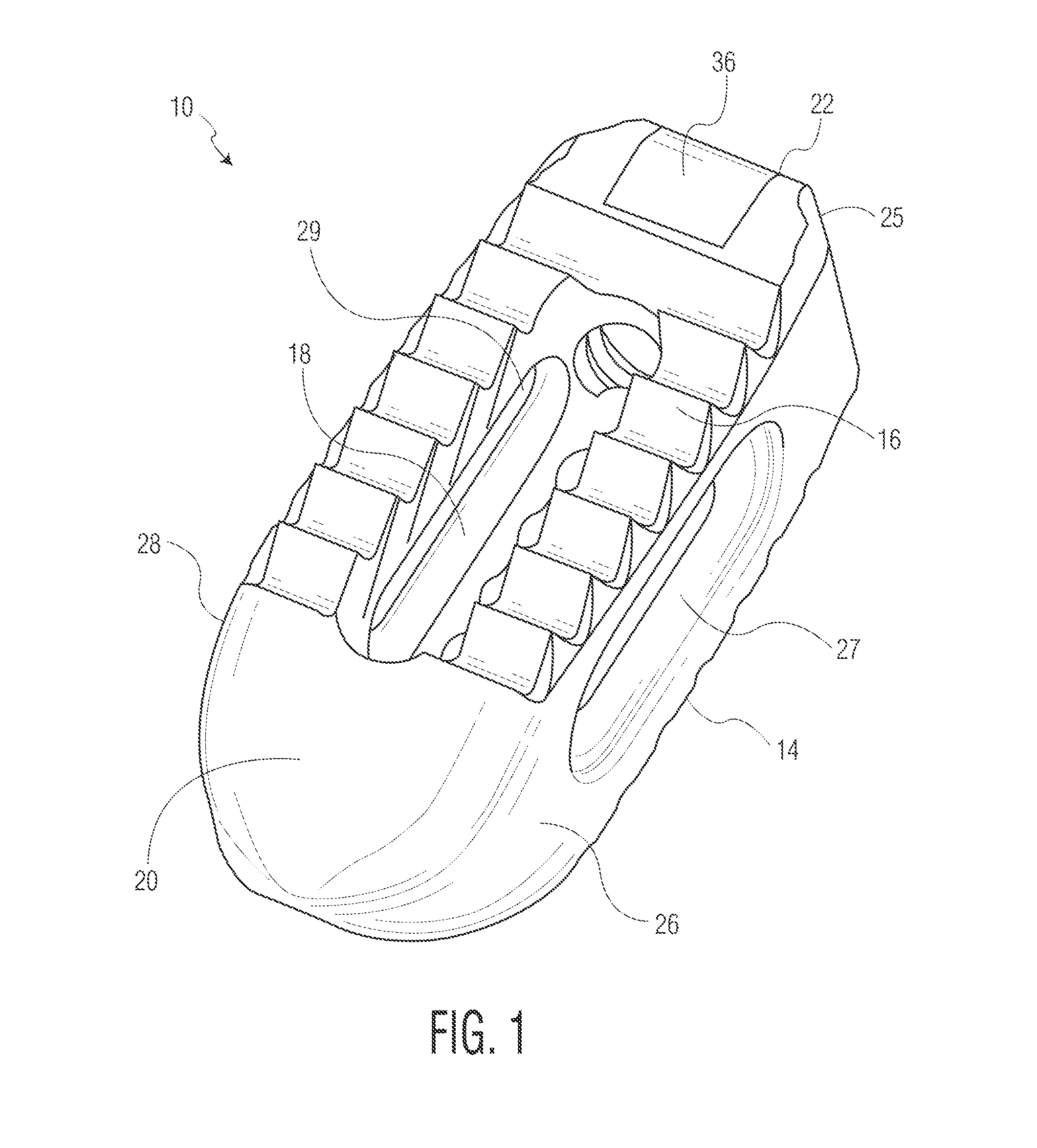
FIG. 1 is a front perspective view of an implant according to one embodiment of the present invention.
FIGS. 2A and 2B are rear perspective views of the implant of FIG. 1.
FIG. 3 is a side view of the implant of FIG. 1.
FIGS. 4A and 4B are top views of the implant of FIG. 1.
FIG. 5 is a rear view of the implant of FIG. 1.
FIG. 6 is a cross-sectional view of the implant of FIG. 1 take along line 6-6 of FIG. 5.
FIG. 7 is an enlarged cross-sectional view of serrations of the implant of FIG. 1.
FIGS. 8A-8B are cross-sectional views of the implant of FIG. 1 take along lines 8A-8A and 8B-8B of FIGS. 4A and 4B, respectively.
FIGS. 9A-9C are views illustrating a constructed version of the implant of FIG. 1.
FIG. 10 is a fluoroscopic view of an implanted implant of FIG. 1.
FIGS. 11A-11C are views of implants according to other embodiments of the present invention.
FIGS. 12A-12C are views of implants according to other embodiments of the present invention.
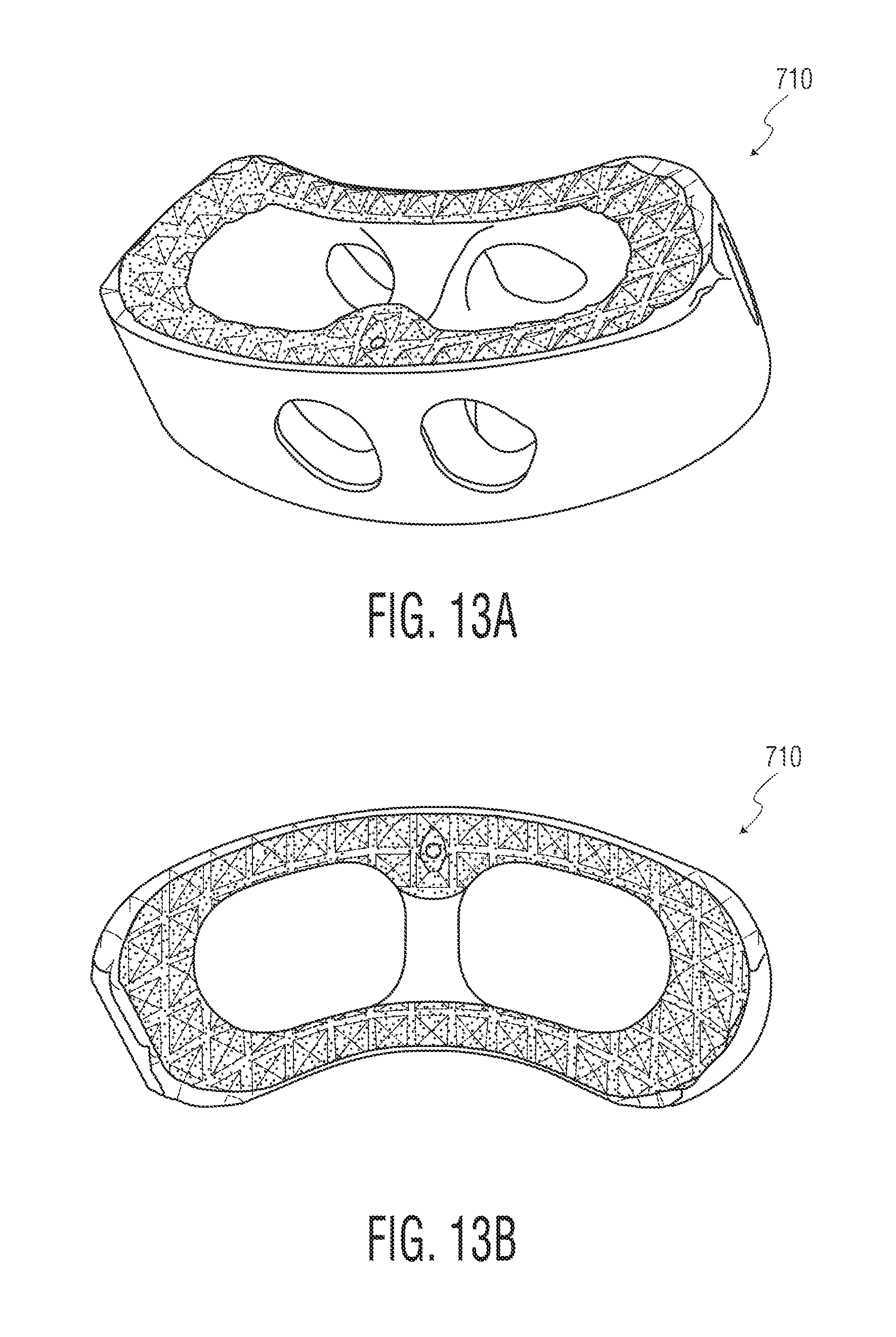
FIGS. 13A-13B are views of implants according to other embodiments of the present invention.
FIGS. 14A-14B are views of implants according to other embodiments of the present invention.
FIGS. 15A-15C are views of implants according to other embodiments of the present invention.
FIG. 16 depicts yet another implant according to another embodiment of the present invention.
DETAILED DESCRIPTION
An implant 10 according to a first embodiment of the present invention is depicted in FIGS. 1-10. Implant 10 is shown as an implant suitable for implantation from a posterior approach. However, as will be readily apparent from the below discussion pertaining to other embodiments, the present invention is not limited to any particular type of implant design. Rather, it is contemplated that certain features of the present invention can be implemented in different types of implants. For instance, implants according to the present invention can be adapted for implantation from anterior or lateral aspects of the patient, as will be discussed below. Moreover, although disclosed as being constructed of metallic materials, it is contemplated that implants according to the present invention may be constructed of polymeric materials such as PEEK or the like. Additionally, each of the embodiments shown in the drawings are designed for placement between adjacent vertebral bodies. However, it is contemplated that implants in accordance with the present invention may be designed for use as vertebral body replacements.
Implant 10 is shown including upper and lower surfaces 12 and 14, respectively. Each surface includes a plurality of serrations 16 at least covering a portion of the surface. While a specific serration design is depicted in the drawings and described in more detail below, many different serration designs can be employed. Implant 10 also includes a cavity 18 formed through a central portion of the implant and each of surfaces 12 and 14. Cavity 18 can be sized and shaped differently from what is shown and can be located in other locations of implant 10. Cavity 18 is preferably designed so that bone growth promoting materials can be contained therein to promote bone growth through the implant.
Implant 10 also includes a wedge nose 20, a rear end 22 with a threaded opening 24 and a chamfer interface 25, and sidewalls 26 and 28 through which lateral windows 27 and 29, respectively are formed. Wedge nose 20 is sized and shaped so as to distract vertebral bodies during insertion of the implant into the intervertebral space. Threaded opening 24 and chamfer interface 25 are configured to cooperate with an insertion tool (not shown in detail). Lateral windows 27 and 29 act to both reduce the stiffness of implant 10 and allow for visualization through the lateral aspect of the implant under fluoroscopy imaging. Of course, the specific sizes and shapes of these elements may vary in other embodiment implants in accordance with the present invention, including certain embodiments discussed below. For instance, certain of the surfaces of implant 10 are shown as smooth and rounded to reduce the potential for soft tissue damage during an implantation procedure, but can be configured differently.
Implant 10 is formed of both solid and porous portions. The porous portions are located on upper and lower surfaces 12, 14, as well as on certain of the internal surfaces of the implant, which allows for bone to grow into a significant portion of the implant. This can best be seen in FIGS. 2B, 4B, 8B, and 9A-9C, where the porous surfaces of implant 10 are shown with different shading. In one embodiment, the porous surfaces have an average pore diameter between 100-1000 microns with a 30-80% porosity, while a preferred embodiment would have a porosity between 55-65%. The porous surfaces may also have any thickness, for instance between 500-4500 microns, and preferably between 500-1500 microns. This results in a surface that is both strong enough for use in a spinal implant and maximizes bone growth potential. The porous portions of implant 10, as well as the solid portions, can be created through the use of a 3D printing process such as is disclosed in U.S. Pat. Nos. 7,537,664 and 8,147,861; U.S. Patent Application Publications Nos. 2006/0147332, 2007/0142914, 2008/0004709; and U.S. patent application Ser. Nos. 13/441,154 and 13/618,218, the disclosures of which are hereby incorporated by reference herein. It is also contemplated to form any porous portion via another known or hereafter developed procedure, such as laser etching.
With specific reference to FIGS. 2B, 4B and 6-8B, the location of the porous and solid portions of implant 10 will be discussed. In the solid model views of FIGS. 2B and 4B, the porous portions of the implant are shown as darker sections, while the solid portions are depicted in lighter material. The cross-sectional views of FIGS. 6-8B on the other hand depict these portions with different cross hatching. For instance, nose 20 includes a solid, smooth exterior construction. The use of solid metal in this section allows for it to withstand impaction loads during an insertion process, as well as for visualization of its location under fluoroscopy or other imaging. It is shown in FIG. 6 that nose 20 in actuality includes a solid portion 30, a hollow area 32 and a porous region 34. Solid portion 30 is designed to provide the necessary support discussed above, while hollow area 32 is provided in order to decrease the radioopacity of the nose and improve visualization under fluoroscopy imaging. Porous region 34, as will be discussed more fully below, extends into the area within cavity 18. It is contemplated that in other embodiments, porous region 34 may extend partially or completely into hollow area 32. This still acts to decrease the radioopacity of the nose, which improves visualization, but also improve the cleanability, sterilization and powder removal from the implant during processing.
Like nose 20, a significant portion of rear end 22 is formed of solid material, so as to facilitate a strong connection with an insertion tool (not shown in detail). In particular, it is noted that while certain portions of the upper and lower surfaces 12, 14 at the rear end are porous, sections 36 are formed solid as they overlie threaded opening 24. This construction adds the necessary stability to the opening that is required for a solid connection with the insertion tool. Moreover, side walls 26, 28 are, as is best shown in FIGS. 8A and 8B, formed solid on an exterior of implant 10 and porous in an interior thereof. Specifically, with reference to FIG. 8B, the side walls include solid portions 38 and porous portions 40. Again, the inclusion of solid portions 38 provides stability to implant 10. However, as is mentioned above, lateral windows 27, 29 reduce the stiffness of the implant. Solid portions 38 may be any thickness, for instance, within the range of 0.25 mm to 0.5 mm. The solid portions also serve to provide a smooth exterior surface to the implant, which reduces tissue damage during implantation. It is noted that in certain embodiments, material may be machined off of any of the surfaces to create a smooth surface finish, which may further prevent tissue damage during implantation. This is especially true in connection with implanted formed by 3D printing processes, as such often result in even solid portions having a rougher surface finish.
Aside from the above discussed portions that are formed solid, the majority of the remainder of implant 10 is formed porous. Most notably, upper and lower surfaces 12, 14 are largely porous, especially in the portions having serrations 16. However, the serrations themselves include some solid portions. With reference to FIGS. 6 and 7, serrations 16 include solid tips 40 and solid roots 42, with the remainder of their construction including porous sections 44. Solid tips 40 not only provide a strong leading surface for engagement with bone, but also prevent fracture of a porous surface from occurring upon such engagement. Specifically, since the individual components (e.g., struts) of the porous surfaces of implant 10 may not necessarily converge to a point, they may fracture upon application of a force like what would be transmitted to serrations 16 during implantation. Solid core 42 also acts to strengthen serrations 16, by essentially providing a strong foundation for porous sections 44.
The particular shape of serrations 16 is also designed to create a strong initial implant-bone connection, while also allowing for easy insertion of implant 10 into the space between vertebrae. In order to resist back-out of implant 10, serrations 16 are oriented at an angle 46 (see FIG. 7). This angle may be any value, although a value within the range of 60 to 80 degrees is preferable. The angle 48 (see FIG. 7) of solid tips 40 is preferably in the range of 30 to 50 degrees. The height 50 of serrations 60 may be within the range of 0.5 mm to 1.5 mm, while the height 52 of solid tips 40 is dependent upon height 50, but preferably is within the range of 0.25 mm to 0.5 mm. Solid core 42 has a thickness 54, preferably 0.1 mm to 0.3 mm thick. The overall pitch 56 of serrations 16 is preferably between 1.25 mm and 2 mm.
The interior of cavity 18 is largely constructed of porous material, which allows for bone growth in this section as well, and hence fusion through implant 10. This construction has the added benefit of also reducing stiffness of the implant, like lateral windows 27, 29. A fully constructed implant 10 is depicted in FIGS. 9A-9C. As shown, the various solid and porous portions of the implant appear differently to the naked eye. The particular prototype shown in those figures was created via a 3D printing process referred to as additive manufacturing, utilizing a titanium material. FIG. 10 is a fluoroscopic image of implant 10 while in position between two adjacent vertebral bodies. In the particular image shown there, implant 10 is engaged with an insertion tool 60, although the specifics of that tool cannot be seen.
FIGS. 11A-11C depict different embodiment implants 110, 210 and 310, respectively that are each suitable for implantation from a posterior approach, like implant 10. FIGS. 12A-12C depict different embodiment implants 410, 510 and 610, respectively that are each suitable for implantation from a lateral approach. FIGS. 13A-13B depict an implant 710 suitable for implantation from a posterior lateral approach. FIGS. 14A-14B depict an implant 810 suitable for implantation from an anterior approach. Among other ways, those implants differ from implant 10 and each other in the manner in which their solid and porous portions are dispersed throughout the design. Again, solid portions are shown in lighter shading and porous portions are shown in darker shading. These various implant embodiments demonstrate that implants in accordance with the present invention may vary both in their size and shape, as well as in the configuration of their porous and solid portions.
FIGS. 15A-15C depict an implant 910 similar to that of implant 10, albeit with certain specific differences. For instance, nose 920 includes sidewalls (best shown in FIG. 15A) that exhibit an increased angle from that of nose 20. This particular design allows for the implant to be inserted in an orientation that is rotated ninety degrees from the traditional insertion orientation of such an implant. Thereafter, implant 910 is rotated, which may result in an additional distraction from that of the initial insertion. Implant 910 may also be provided with a feature, such as a dimple or the like (not shown), that helps to identify the correct final orientation of the implant. For instance, a dimple may be provided at rear end 922 so that the surgeon may easily identify the final orientation of the implant. Of course, any visual identifier could also be employed.
Implant 910 also includes differently shaped/oriented lateral windows 927, 929 (only window 929 is shown in FIG. 15B) from that of above-discussed windows 27, 29. As shown, windows 927, 929 extend along less of implant 910 than do windows 27, 29 along implant 10. Moreover, the height of windows 927, 929 taper in the same direction as does the height of implant 910. For implants that are not lordotic, the windows may be a constant height. Finally, implant 910 exhibits chamfered edges 923 (best shown in FIG. 15C) that are on the four sides of the implant to eliminate sharp edges an make the implant more suitable for implantation without tissue damage.
FIG. 16 depicts yet another embodiment according to the present invention, cervical implant 1010. This implant is particularly suited for implantation in a cervical area of the spine and includes many elements similar to those of the other embodiment implants. For instance, implant 1010 includes upper and lower surfaces 1012, 1014 which include serrations 1016 similar to those discussed above. Further, the cervical implant includes a tapered nose or leading end 1020 and a trailing end 1022 with an aperture 1024 for engaging an insertion tool. Although other embodiments may vary, implant 1010 is shown as having porous portions at the upper and lower surfaces 1012, 1014 that are similar to those discussed above.
In use, the various implants in accordance with the present invention may be implanted in a manner similar to existing spinal implants. For instance, an insertion tool (e.g., tool 60) may be coupled with the implant to guide the implant into place between vertebral bodies. Initial engagement of the implant with the vertebral bodies is achieved via mechanical coupling elements included on the implant (e.g., serrations 16). Thereafter, bone is permitted to grow into any porous sections on the implant. This bone growth may be promoted through the use of bone growth promoting substances, such as allograft materials placed within cavity 18. After some time, the porosity of the implant preferably allows for a stronger fusion than that of existing, nonporous implants.
In creating an implant such as implant 10, the aforementioned 3D printing process can be utilized (see e.g., FIGS. 9A-9C). Because of the construction of the implant, it may be beneficial to orient the construction in one manner or the like. For instance, it has been found that orienting the build so that nose 20 faces down (i.e., is built first) results in better serration 16 creation. Of course, the nose down orientation is only one of many that can be employed and the creation of implants according to the present invention is not to be so limited.
Although the invention herein has been described with reference to particular embodiments, it is to be understood that these embodiments are merely illustrative of the principles and applications of the present invention. It is therefore to be understood that numerous modifications may be made to the illustrative embodiments and that other arrangements may be devised without departing from the spirit and scope of the present invention as defined by the appended claims.
* * * * *
D00000
D00001
D00002
D00003
D00004
D00005
D00006
D00007
D00008
D00009
D00010
D00011
D00012
D00013

D00014

D00015

XML
uspto.report is an independent third-party trademark research tool that is not affiliated, endorsed, or sponsored by the United States Patent and Trademark Office (USPTO) or any other governmental organization. The information provided by uspto.report is based on publicly available data at the time of writing and is intended for informational purposes only.
While we strive to provide accurate and up-to-date information, we do not guarantee the accuracy, completeness, reliability, or suitability of the information displayed on this site. The use of this site is at your own risk. Any reliance you place on such information is therefore strictly at your own risk.
All official trademark data, including owner information, should be verified by visiting the official USPTO website at www.uspto.gov. This site is not intended to replace professional legal advice and should not be used as a substitute for consulting with a legal professional who is knowledgeable about trademark law.