Interbody device with opening to allow packing graft and other biologics
Georges Ja
U.S. patent number 10,182,921 [Application Number 13/673,061] was granted by the patent office on 2019-01-22 for interbody device with opening to allow packing graft and other biologics. This patent grant is currently assigned to DePuy Synthes Products, Inc.. The grantee listed for this patent is DePuy Synthes Products, Inc.. Invention is credited to Bacem Georges.


| United States Patent | 10,182,921 |
| Georges | January 22, 2019 |
Interbody device with opening to allow packing graft and other biologics
Abstract
An intervertebral fusion device having a cage having an opening or window in its front wall that allows for the insertion of bone graft therethrough after the cage has been placed into the disc space. The device further has a faceplate that covers the front wall of the cage and provides features for securing bone screws to the adjacent vertebral bodies.
| Inventors: | Georges; Bacem (Franklin, MA) | ||||||||||
|---|---|---|---|---|---|---|---|---|---|---|---|
| Applicant: |
|
||||||||||
| Assignee: | DePuy Synthes Products, Inc.
(Raynham, MA) |
||||||||||
| Family ID: | 50682455 | ||||||||||
| Appl. No.: | 13/673,061 | ||||||||||
| Filed: | November 9, 2012 |
Prior Publication Data
| Document Identifier | Publication Date | |
|---|---|---|
| US 20140135930 A1 | May 15, 2014 | |
| Current U.S. Class: | 1/1 |
| Current CPC Class: | A61F 2/4455 (20130101); A61F 2002/2835 (20130101); A61F 2/4611 (20130101); A61F 2/30744 (20130101); A61B 17/86 (20130101); A61F 2002/30904 (20130101); A61F 2002/30482 (20130101) |
| Current International Class: | A61F 2/44 (20060101); A61F 2/30 (20060101); A61F 2/46 (20060101); A61B 17/86 (20060101); A61F 2/28 (20060101) |
| Field of Search: | ;623/17.11,17.16 ;606/286-290 |
References Cited [Referenced By]
U.S. Patent Documents
| 1636636 | July 1927 | Humble |
| 1677337 | July 1928 | Grove |
| 2304703 | December 1942 | O'Leary |
| 4105034 | August 1978 | Shalaby |
| 4130639 | December 1978 | Shalaby |
| 4140678 | February 1979 | Shalaby |
| 4141087 | February 1979 | Shalaby |
| 4205399 | June 1980 | Shalaby |
| 4208511 | June 1980 | Shalaby |
| 4743256 | May 1988 | Brantigan |
| 4904261 | February 1990 | Dove |
| 4955908 | September 1990 | Frey |
| 5041113 | August 1991 | Biedermann et al. |
| 5123926 | June 1992 | Pisharodi |
| 5147361 | September 1992 | Ojima et al. |
| 5209751 | May 1993 | Farris et al. |
| 5306308 | April 1994 | Gross et al. |
| 5352231 | October 1994 | Brumfield |
| 5391170 | February 1995 | McGuire |
| 5395372 | March 1995 | Holt |
| 5397364 | March 1995 | Kozak |
| 5443514 | August 1995 | Steffee |
| 5443515 | August 1995 | Cohen |
| 5464407 | November 1995 | McGuire |
| 5464929 | November 1995 | Bezwada |
| 5499986 | March 1996 | Dimarco |
| 5529580 | June 1996 | Kusunoki |
| 5534031 | July 1996 | Matsuzaki |
| 5578034 | November 1996 | Estes |
| 5591166 | January 1997 | Bernhardt et al. |
| 5595751 | January 1997 | Bezwada |
| 5597579 | January 1997 | Bezwada |
| 5601553 | February 1997 | Trebing et al. |
| 5607687 | March 1997 | Bezwada |
| 5609636 | March 1997 | Kohrs et al. |
| 5618552 | April 1997 | Bezwada |
| 5620458 | April 1997 | Green et al. |
| 5620698 | April 1997 | Bezwada |
| 5645598 | July 1997 | Brosnahan, III |
| 5645850 | July 1997 | Bezwada |
| 5648088 | July 1997 | Bezwada |
| 5662655 | September 1997 | Laboureau |
| 5676666 | October 1997 | Oxland et al. |
| 5698213 | December 1997 | Jamiolkowski |
| 5700583 | December 1997 | Jamiolkowski |
| 5713899 | February 1998 | Marnay |
| 5716415 | February 1998 | Steffee |
| 5755796 | May 1998 | Ibo et al. |
| 5776196 | July 1998 | Matsuzaki |
| 5779707 | July 1998 | Bertholet |
| 5785713 | July 1998 | Jobe |
| 5788698 | August 1998 | Savornin |
| 5797912 | August 1998 | Runciman et al. |
| 5797918 | August 1998 | McGuire |
| 5800435 | September 1998 | Errico et al. |
| 5800440 | September 1998 | Stead |
| 5859150 | January 1999 | Jamiolkowski |
| 5888223 | March 1999 | Bray, Jr. |
| 5904689 | May 1999 | Jonjic |
| 5913860 | June 1999 | Scholl |
| 6039761 | March 2000 | Li et al. |
| 6049026 | April 2000 | Muschler |
| 6056749 | May 2000 | Kuslich |
| 6066175 | May 2000 | Henderson |
| 6086593 | July 2000 | Bonutti |
| 6093205 | July 2000 | McLeod |
| 6099531 | August 2000 | Bonutti |
| 6106557 | August 2000 | Robioneck et al. |
| 6117174 | September 2000 | Nolan |
| 6120503 | September 2000 | Michelson |
| 6126689 | October 2000 | Brett |
| 6139550 | October 2000 | Michelson |
| 6156037 | December 2000 | LeHuec |
| 6159211 | December 2000 | Boriani |
| 6159244 | December 2000 | Suddaby |
| 6174311 | January 2001 | Branch et al. |
| 6179875 | January 2001 | Von Strempel |
| 6190414 | February 2001 | Young et al. |
| 6193757 | February 2001 | Foley et al. |
| 6200306 | March 2001 | Klostermeyer |
| 6206922 | March 2001 | Zdeblick |
| 6224602 | May 2001 | Hayes |
| 6231610 | May 2001 | Geisler |
| 6235059 | May 2001 | Benezech |
| 6306170 | October 2001 | Ray |
| 6330845 | December 2001 | Meulink |
| 6336928 | January 2002 | Guerin |
| 6342055 | January 2002 | Eisermann |
| 6342074 | January 2002 | Simpson |
| 6364880 | April 2002 | Michelson |
| 6368351 | April 2002 | Glenn et al. |
| 6375462 | April 2002 | Holweg et al. |
| 6387130 | May 2002 | Stone |
| 6395031 | May 2002 | Foley et al. |
| 6406478 | June 2002 | Kuo |
| 6409766 | June 2002 | Brett |
| 6413278 | July 2002 | Marchosky |
| 6423063 | July 2002 | Bonutti |
| 6428575 | August 2002 | Koo |
| 6432106 | August 2002 | Fraser |
| 6447544 | September 2002 | Michelson |
| 6447546 | September 2002 | Bramlet et al. |
| 6454769 | September 2002 | Wagner et al. |
| 6461359 | October 2002 | Tribus |
| 6471724 | October 2002 | Zdeblick |
| 6488710 | December 2002 | Besselink |
| 6508818 | January 2003 | Steiner et al. |
| 6558387 | May 2003 | Errico |
| 6558423 | May 2003 | Michelson |
| 6562073 | May 2003 | Foley |
| 6565570 | May 2003 | Sterett |
| 6572619 | June 2003 | Santilli |
| 6579290 | June 2003 | Hardcastle |
| 6602257 | August 2003 | Thramann |
| 6629998 | October 2003 | Lin |
| 6682563 | January 2004 | Scharf |
| 6695846 | February 2004 | Richelsoph |
| 6730125 | May 2004 | Lin |
| 6730127 | May 2004 | Michelson |
| 6733531 | May 2004 | Trieu |
| 6736850 | May 2004 | Davis |
| 6743257 | June 2004 | Castro |
| 6745255 | June 2004 | Yen et al. |
| 6761738 | July 2004 | Boyd |
| 6770096 | August 2004 | Bolger |
| 6773437 | August 2004 | Ogilvie |
| 6776781 | August 2004 | Uwaydah |
| 6805714 | October 2004 | Sutcliffe |
| 6808537 | October 2004 | Michelson |
| 6824564 | November 2004 | Crozet |
| 6824565 | November 2004 | Muhanna et al. |
| 6833006 | December 2004 | Foley et al. |
| 6835208 | December 2004 | Marchosky |
| 6837905 | January 2005 | Lieberman |
| 6849093 | February 2005 | Michelson |
| 6890335 | May 2005 | Grabowski et al. |
| 6890355 | May 2005 | Michelson |
| 6945973 | September 2005 | Bray |
| 6972019 | December 2005 | Michelson |
| 6974479 | December 2005 | Trieu |
| 6974480 | December 2005 | Messerli et al. |
| 6984234 | January 2006 | Bray |
| 7001385 | February 2006 | Bonutti |
| 7033394 | April 2006 | Michelson |
| 7041135 | May 2006 | Michelson |
| 7044971 | May 2006 | Suddaby |
| 7056341 | June 2006 | Crozet |
| 7063491 | June 2006 | French |
| 7070598 | July 2006 | Lim et al. |
| 7077864 | July 2006 | Byrd, III |
| 7087055 | August 2006 | Lim et al. |
| 7112222 | September 2006 | Fraser |
| 7112223 | September 2006 | Davis |
| 7135024 | November 2006 | Cook |
| 7135043 | November 2006 | Nakahara |
| 7163561 | January 2007 | Michelson |
| 7172627 | February 2007 | Fiere |
| 7226482 | June 2007 | Messerli |
| 7232463 | June 2007 | Falahee |
| 7232464 | June 2007 | Mathieu |
| 7238203 | July 2007 | Bagga |
| 7238206 | July 2007 | Lange |
| 7255698 | August 2007 | Michelson |
| 7276081 | October 2007 | Coates |
| 7288094 | October 2007 | Lindemann |
| 7288095 | October 2007 | Baynham et al. |
| 7288114 | October 2007 | Lange |
| 7306605 | December 2007 | Ross |
| 7309358 | December 2007 | Berry |
| 7311734 | December 2007 | Van Hoeck |
| 7316714 | January 2008 | Gordon |
| 7318839 | January 2008 | Malberg et al. |
| 7323011 | January 2008 | Shepard |
| 7326248 | February 2008 | Michelson |
| 7338525 | March 2008 | Ferree |
| 7341587 | March 2008 | Molz, IV |
| 7341590 | March 2008 | Ferree |
| 7354452 | April 2008 | Foley |
| 7361193 | April 2008 | Frey |
| 7435262 | October 2008 | Michelson |
| 7438715 | October 2008 | Doubler |
| 7442209 | October 2008 | Michelson |
| 7452370 | November 2008 | Anderson |
| 7491237 | February 2009 | Randall |
| 7527641 | May 2009 | Suh |
| 7594931 | September 2009 | Louis |
| 7594932 | September 2009 | Aferzon |
| 7601171 | October 2009 | Ainsworth et al. |
| 7601173 | October 2009 | Messerli |
| 7608062 | October 2009 | Sweeney |
| 7618456 | November 2009 | Mathieu |
| 7628816 | December 2009 | Magerl |
| 7641665 | January 2010 | Zubok |
| 7655042 | February 2010 | Foley et al. |
| 7662182 | February 2010 | Zubok |
| 7674279 | March 2010 | Johnson |
| 7704255 | April 2010 | Michelson |
| 7726002 | June 2010 | Shimp et al. |
| 7794502 | September 2010 | Michelson |
| 7815643 | October 2010 | Johnson et al. |
| 7815681 | October 2010 | Ferguson |
| 7846206 | December 2010 | Leonard et al. |
| 7846210 | December 2010 | Perez-Cruet et al. |
| 7871441 | January 2011 | Eckman |
| 7875062 | January 2011 | Lindemann |
| 7875076 | January 2011 | Mathieu |
| 7883531 | February 2011 | de Coninck |
| 7887591 | February 2011 | Aebi et al. |
| 7887595 | February 2011 | Pimenta |
| 7909877 | March 2011 | Krueger et al. |
| 7993403 | August 2011 | Foley et al. |
| 8002808 | August 2011 | Morrison et al. |
| 8007523 | August 2011 | Wagner |
| 8187329 | May 2012 | Theofilos |
| 8206423 | June 2012 | Siegal |
| 8216312 | July 2012 | Gray |
| 8236029 | August 2012 | Siegal |
| 8241328 | August 2012 | Siegal |
| 8246622 | August 2012 | Siegal et al. |
| 8323342 | December 2012 | Schwab |
| 8328812 | December 2012 | Siegal et al. |
| 8336559 | December 2012 | Kallabat et al. |
| 8337559 | December 2012 | Hansell et al. |
| 8343219 | January 2013 | Allain |
| 8349015 | January 2013 | Bae et al. |
| 8357200 | January 2013 | Adl |
| 8454694 | June 2013 | Armstrong et al. |
| 8460385 | June 2013 | Wensel |
| 8460387 | June 2013 | Theofilos |
| 8465524 | June 2013 | Siegal |
| 8470044 | June 2013 | Bertholet et al. |
| 8480747 | July 2013 | Melkent et al. |
| 8486109 | July 2013 | Siegal |
| 8491658 | July 2013 | Etminan |
| 8496691 | July 2013 | Blain |
| 8496708 | July 2013 | Blain |
| 8500783 | August 2013 | Baynham |
| 8540769 | September 2013 | Janowski |
| 8551175 | October 2013 | Wensel |
| 8562651 | October 2013 | Metcalf et al. |
| 8597330 | December 2013 | Siegal |
| 8613772 | December 2013 | Bray et al. |
| 8617245 | December 2013 | Brett |
| 8628578 | January 2014 | Miller et al. |
| 8641765 | February 2014 | Muhanna |
| 8672977 | March 2014 | Siegal et al. |
| 8690928 | April 2014 | Walkenhorst et al. |
| 8690948 | April 2014 | Armstrong et al. |
| 8747443 | June 2014 | Aferzon |
| 8758439 | June 2014 | Linares |
| 8777993 | July 2014 | Siegal et al. |
| 8821555 | September 2014 | Bae |
| 8845638 | September 2014 | Siegal et al. |
| 8900235 | December 2014 | Siegal |
| 8906098 | December 2014 | Siegal |
| 8932359 | January 2015 | Brett |
| 8956416 | February 2015 | McCarthy |
| 9005293 | April 2015 | Moskowitz et al. |
| 9005295 | April 2015 | Kueenzi et al. |
| 9017408 | April 2015 | Siegal et al. |
| 9017413 | April 2015 | Siegal et al. |
| 9044334 | June 2015 | Siegal et al. |
| 9138330 | September 2015 | Hansell et al. |
| 9192419 | November 2015 | McDonough et al. |
| 9248028 | February 2016 | Gamache |
| 9254138 | February 2016 | Siegal et al. |
| 9265546 | February 2016 | Blain |
| 9265621 | February 2016 | Voellmicke |
| 9278009 | March 2016 | Bray et al. |
| 9283091 | March 2016 | Melkent |
| 9283092 | March 2016 | Siegal et al. |
| 9289311 | March 2016 | Whipple |
| 9402738 | August 2016 | Niemic |
| 9408712 | August 2016 | Siegal et al. |
| 9492286 | November 2016 | Biedermann |
| 9662225 | May 2017 | Pavento et al. |
| 9668877 | June 2017 | Pavento et al. |
| 9848992 | December 2017 | McDonough et al. |
| 2001/0031968 | October 2001 | Dorchak et al. |
| 2002/0029044 | March 2002 | Monassevitch |
| 2002/0029082 | March 2002 | Muhanna |
| 2002/0095155 | July 2002 | Michelson |
| 2002/0138146 | September 2002 | Jackson |
| 2002/0143328 | October 2002 | Shluzas |
| 2002/0151976 | October 2002 | Foley et al. |
| 2002/0156475 | October 2002 | Lerch et al. |
| 2003/0004576 | January 2003 | Thalgott |
| 2003/0028197 | February 2003 | Hanson et al. |
| 2003/0045940 | March 2003 | Eberlein et al. |
| 2003/0050645 | March 2003 | Parker |
| 2003/0083748 | May 2003 | Lee et al. |
| 2003/0100949 | May 2003 | Michelson |
| 2003/0125739 | July 2003 | Bagga |
| 2003/0130739 | July 2003 | Gerbec et al. |
| 2003/0153975 | August 2003 | Byrd |
| 2003/0158555 | August 2003 | Sanders |
| 2003/0187440 | October 2003 | Richelsoph et al. |
| 2003/0187506 | October 2003 | Ross |
| 2003/0195632 | October 2003 | Foley |
| 2003/0225409 | December 2003 | Freid et al. |
| 2004/0024464 | February 2004 | Errico |
| 2004/0034430 | February 2004 | Falahee |
| 2004/0092929 | May 2004 | Zindrick |
| 2004/0106996 | June 2004 | Liu et al. |
| 2004/0111089 | June 2004 | Stevens et al. |
| 2004/0127902 | July 2004 | Suzuki |
| 2004/0127990 | July 2004 | Bartish |
| 2004/0138662 | July 2004 | Landry et al. |
| 2004/0153065 | August 2004 | Lim |
| 2004/0153072 | August 2004 | Bonutti |
| 2004/0167625 | August 2004 | Beyar et al. |
| 2004/0199253 | October 2004 | Link |
| 2004/0199254 | October 2004 | Louis |
| 2004/0210219 | October 2004 | Bray |
| 2004/0249377 | December 2004 | Kaes |
| 2004/0254644 | December 2004 | Taylor |
| 2004/0260286 | December 2004 | Ferree |
| 2005/0021144 | January 2005 | Malberg et al. |
| 2005/0033433 | February 2005 | Michelson |
| 2005/0038513 | February 2005 | Michelson |
| 2005/0043800 | February 2005 | Paul et al. |
| 2005/0065608 | March 2005 | Michelson |
| 2005/0071006 | March 2005 | Kirschman |
| 2005/0071008 | March 2005 | Kirschman |
| 2005/0085913 | April 2005 | Fraser |
| 2005/0096657 | May 2005 | Autericque et al. |
| 2005/0101960 | May 2005 | Fiere et al. |
| 2005/0113920 | May 2005 | Foley et al. |
| 2005/0143749 | June 2005 | Zalenski |
| 2005/0143827 | June 2005 | Globerman et al. |
| 2005/0149192 | July 2005 | Zucherman |
| 2005/0149193 | July 2005 | Zucherman |
| 2005/0154391 | July 2005 | Doherty et al. |
| 2005/0159813 | July 2005 | Molz |
| 2005/0177240 | August 2005 | Blain |
| 2005/0177245 | August 2005 | Leatherbury et al. |
| 2005/0182416 | August 2005 | Lim et al. |
| 2005/0209696 | September 2005 | Lin et al. |
| 2005/0251260 | November 2005 | Gerber et al. |
| 2005/0261768 | November 2005 | Trieu |
| 2005/0277938 | December 2005 | Parsons |
| 2005/0278036 | December 2005 | Leonard |
| 2006/0025860 | February 2006 | Li |
| 2006/0030851 | February 2006 | Bray |
| 2006/0058801 | March 2006 | Schlienger et al. |
| 2006/0079961 | April 2006 | Michelson |
| 2006/0085071 | April 2006 | Lechmann |
| 2006/0129424 | June 2006 | Chan |
| 2006/0142765 | June 2006 | Dixon |
| 2006/0142858 | June 2006 | Colleran et al. |
| 2006/0142863 | June 2006 | Fraser |
| 2006/0178745 | August 2006 | Bartish et al. |
| 2006/0211952 | September 2006 | Kennedy |
| 2006/0229609 | October 2006 | Wang |
| 2006/0229729 | October 2006 | Gordon et al. |
| 2006/0235403 | October 2006 | Blain |
| 2006/0235409 | October 2006 | Blain |
| 2006/0235411 | October 2006 | Blain et al. |
| 2006/0235518 | October 2006 | Blain |
| 2006/0235535 | October 2006 | Ferree |
| 2006/0241597 | October 2006 | Mitchell et al. |
| 2006/0241761 | October 2006 | Gately |
| 2006/0247650 | November 2006 | Yerby et al. |
| 2006/0259147 | November 2006 | Krishna et al. |
| 2006/0293753 | December 2006 | Thramann |
| 2007/0049941 | March 2007 | Thramann |
| 2007/0055252 | March 2007 | Blain |
| 2007/0067035 | March 2007 | Falahee |
| 2007/0073398 | March 2007 | Fabian et al. |
| 2007/0106384 | May 2007 | Bray |
| 2007/0106388 | May 2007 | Michelson |
| 2007/0129804 | June 2007 | Bentley |
| 2007/0162138 | July 2007 | Heinz |
| 2007/0198016 | August 2007 | Zang et al. |
| 2007/0213737 | September 2007 | Schemmerhorn et al. |
| 2007/0219635 | September 2007 | Mathieu |
| 2007/0233118 | October 2007 | McLain |
| 2007/0233253 | October 2007 | Bray |
| 2007/0233261 | October 2007 | Lopez et al. |
| 2007/0233263 | October 2007 | Melkent |
| 2007/0250167 | October 2007 | Bray |
| 2007/0255146 | November 2007 | Andrews et al. |
| 2007/0255416 | November 2007 | Melkent et al. |
| 2007/0265631 | November 2007 | Fox |
| 2007/0270957 | November 2007 | Heinz |
| 2007/0270965 | November 2007 | Ferguson |
| 2007/0276490 | November 2007 | Mateyka |
| 2007/0282449 | December 2007 | De Villiers et al. |
| 2007/0293948 | December 2007 | Bagga |
| 2007/0299521 | December 2007 | Glenn et al. |
| 2008/0015694 | January 2008 | Tribus |
| 2008/0027550 | January 2008 | Link |
| 2008/0033440 | February 2008 | Moskowitz |
| 2008/0051890 | February 2008 | Waugh et al. |
| 2008/0051897 | February 2008 | Lopez et al. |
| 2008/0065219 | March 2008 | Dye |
| 2008/0077247 | March 2008 | Murillo |
| 2008/0082173 | April 2008 | Delurio |
| 2008/0097436 | April 2008 | Culbert |
| 2008/0103597 | May 2008 | Lechman et al. |
| 2008/0103598 | May 2008 | Trudeau et al. |
| 2008/0109005 | May 2008 | Trudeau et al. |
| 2008/0125865 | May 2008 | Abdelgany |
| 2008/0132949 | June 2008 | Aferzon |
| 2008/0132958 | June 2008 | Pech |
| 2008/0133012 | June 2008 | McGuckin |
| 2008/0133014 | June 2008 | Gately et al. |
| 2008/0161925 | July 2008 | Brittan |
| 2008/0167666 | July 2008 | Fiere |
| 2008/0177307 | July 2008 | Moskowitz |
| 2008/0183293 | July 2008 | Parry |
| 2008/0183294 | July 2008 | Adl |
| 2008/0221690 | September 2008 | Chaput |
| 2008/0221694 | September 2008 | Warnick et al. |
| 2008/0234822 | September 2008 | Govil et al. |
| 2008/0243136 | October 2008 | Prager |
| 2008/0249569 | October 2008 | Waugh |
| 2008/0249575 | October 2008 | Waugh |
| 2008/0249625 | October 2008 | Waugh |
| 2008/0255620 | October 2008 | Strauss |
| 2008/0269806 | October 2008 | Zhang |
| 2008/0281425 | November 2008 | Thalgott |
| 2008/0294262 | November 2008 | Levieux |
| 2008/0300601 | December 2008 | Fabian et al. |
| 2008/0300634 | December 2008 | Gray |
| 2008/0306596 | December 2008 | Jones |
| 2008/0306598 | December 2008 | Hansen |
| 2008/0312698 | December 2008 | Bergeron |
| 2008/0312742 | December 2008 | Abernathie |
| 2009/0012529 | January 2009 | Blain et al. |
| 2009/0030421 | January 2009 | Hawkins et al. |
| 2009/0030519 | January 2009 | Falahee |
| 2009/0030520 | January 2009 | Biedermann |
| 2009/0062921 | March 2009 | Michelson |
| 2009/0088849 | April 2009 | Armstrong |
| 2009/0099554 | April 2009 | Forster |
| 2009/0099610 | April 2009 | Johnson et al. |
| 2009/0099661 | April 2009 | Bhattacharya et al. |
| 2009/0105771 | April 2009 | Lei |
| 2009/0105774 | April 2009 | Jones |
| 2009/0105830 | April 2009 | Jones et al. |
| 2009/0105831 | April 2009 | Jones |
| 2009/0125028 | May 2009 | Teisen et al. |
| 2009/0131988 | May 2009 | Bush, Jr. |
| 2009/0132054 | May 2009 | Zeegers |
| 2009/0143859 | June 2009 | McClellan, III |
| 2009/0164020 | June 2009 | Janowski |
| 2009/0182428 | July 2009 | McClellan et al. |
| 2009/0182430 | July 2009 | Tyber |
| 2009/0192549 | July 2009 | Sanders |
| 2009/0192613 | July 2009 | Wing |
| 2009/0192615 | July 2009 | Tyber |
| 2009/0192616 | July 2009 | Zielinski |
| 2009/0198245 | August 2009 | Phan |
| 2009/0198287 | August 2009 | Chiu |
| 2009/0198339 | August 2009 | Kleiner et al. |
| 2009/0210062 | August 2009 | Thalgott |
| 2009/0210064 | August 2009 | Lechmann |
| 2009/0224023 | September 2009 | Moskowitz et al. |
| 2009/0234364 | September 2009 | Crook |
| 2009/0248092 | October 2009 | Bellas et al. |
| 2009/0259316 | October 2009 | Ginn et al. |
| 2009/0265007 | October 2009 | Colleran |
| 2009/0270873 | October 2009 | Fabian |
| 2009/0287251 | November 2009 | Bae |
| 2009/0306779 | December 2009 | Ahn |
| 2009/0326543 | December 2009 | Fabian |
| 2009/0326580 | December 2009 | Anderson et al. |
| 2009/0326589 | December 2009 | Lemoine et al. |
| 2010/0004747 | January 2010 | Lin |
| 2010/0016901 | January 2010 | Robinson |
| 2010/0016973 | January 2010 | De Villiers et al. |
| 2010/0023128 | January 2010 | Malberg |
| 2010/0030334 | February 2010 | Molz, IV |
| 2010/0036496 | February 2010 | Yu |
| 2010/0042159 | February 2010 | Butler |
| 2010/0057206 | March 2010 | Duffield |
| 2010/0069969 | March 2010 | Ampuero |
| 2010/0070037 | March 2010 | Parry et al. |
| 2010/0087925 | April 2010 | Kostuik |
| 2010/0106249 | April 2010 | Tyber et al. |
| 2010/0137987 | June 2010 | Diao et al. |
| 2010/0145457 | June 2010 | Felt |
| 2010/0145459 | June 2010 | McDonough |
| 2010/0145460 | June 2010 | McDonough et al. |
| 2010/0179656 | July 2010 | Theofilos |
| 2010/0185287 | July 2010 | Allard et al. |
| 2010/0185289 | July 2010 | Kirwan et al. |
| 2010/0185292 | July 2010 | Hochschuler et al. |
| 2010/0204739 | August 2010 | Bae et al. |
| 2010/0217325 | August 2010 | Hochschuler et al. |
| 2010/0217393 | August 2010 | Theofilos |
| 2010/0249935 | September 2010 | Slivka |
| 2010/0249937 | September 2010 | Blain et al. |
| 2010/0286777 | November 2010 | Errico |
| 2010/0286781 | November 2010 | Bullard |
| 2010/0286783 | November 2010 | Lechmann et al. |
| 2010/0292696 | November 2010 | Chantelot |
| 2010/0292737 | November 2010 | Suh |
| 2010/0305704 | December 2010 | Messerli |
| 2010/0312345 | December 2010 | Duffield |
| 2010/0312346 | December 2010 | Kueenzi et al. |
| 2011/0009908 | January 2011 | Ferguson |
| 2011/0009966 | January 2011 | Michelson |
| 2011/0015675 | January 2011 | Howard |
| 2011/0015745 | January 2011 | Bucci |
| 2011/0082550 | April 2011 | Yeh |
| 2011/0082555 | April 2011 | Martz |
| 2011/0098747 | April 2011 | Donner |
| 2011/0106159 | May 2011 | Nazeck |
| 2011/0144703 | June 2011 | Krause |
| 2011/0166656 | July 2011 | Thalgott et al. |
| 2011/0184415 | July 2011 | Anderson et al. |
| 2011/0190892 | August 2011 | Kirschman |
| 2011/0202136 | August 2011 | Brittan et al. |
| 2011/0213421 | September 2011 | Binder et al. |
| 2011/0230971 | September 2011 | Donner |
| 2011/0251689 | October 2011 | Seifert et al. |
| 2011/0282453 | November 2011 | Greenhalgh |
| 2011/0319896 | December 2011 | Papenfusse |
| 2011/0319998 | December 2011 | O'Neil |
| 2012/0041559 | February 2012 | Melkent et al. |
| 2012/0078371 | March 2012 | Gamache |
| 2012/0078372 | March 2012 | Gamache |
| 2012/0078373 | March 2012 | Gamache |
| 2012/0083889 | April 2012 | Purcell et al. |
| 2012/0143336 | June 2012 | Aflatoon |
| 2012/0150301 | June 2012 | Gamache |
| 2012/0150303 | June 2012 | Linares |
| 2012/0158143 | June 2012 | Shapiro |
| 2012/0191190 | July 2012 | Trieu |
| 2012/0197401 | August 2012 | Duncan et al. |
| 2012/0203230 | August 2012 | Adams |
| 2012/0209331 | August 2012 | Michelson |
| 2012/0226319 | September 2012 | Armstrong et al. |
| 2012/0253406 | October 2012 | Bae |
| 2013/0060337 | March 2013 | Petersheim et al. |
| 2013/0073044 | March 2013 | Gamache |
| 2013/0079883 | March 2013 | Butler et al. |
| 2013/0166027 | June 2013 | Bellas |
| 2013/0238095 | September 2013 | Pavento et al. |
| 2013/0268080 | October 2013 | Melkent et al. |
| 2013/0310939 | November 2013 | Fabian |
| 2013/0325071 | December 2013 | Niemiec et al. |
| 2013/0345813 | December 2013 | Frank et al. |
| 2014/0039623 | February 2014 | Iott et al. |
| 2014/0067069 | March 2014 | Lopez |
| 2014/0107786 | April 2014 | Geisler et al. |
| 2014/0114415 | April 2014 | Tyber |
| 2014/0135930 | May 2014 | Georges |
| 2014/0142705 | May 2014 | Duffield et al. |
| 2014/0156009 | June 2014 | Armstrong et al. |
| 2014/0172103 | June 2014 | O'Neil et al. |
| 2014/0364917 | December 2014 | Sandstrom |
| 2015/0297356 | October 2015 | Gamache |
| 2015/0313721 | November 2015 | Gamache |
| 2015/0374511 | December 2015 | Pavento et al. |
| 2016/0045325 | February 2016 | Bellas et al. |
| 2016/0128846 | May 2016 | Voellmicke |
| 2016/0213487 | July 2016 | Wilson et al. |
| 2016/0317317 | November 2016 | Marchek et al. |
| 2016/0324660 | November 2016 | Pavento et al. |
| 2016/0324662 | November 2016 | McDonough et al. |
| 201244104 | May 2009 | CN | |||
| 19710392 | Jul 1999 | DE | |||
| 1609444 | Dec 2005 | EP | |||
| 1683490 | Jul 2006 | EP | |||
| 1774926 | Apr 2007 | EP | |||
| 1459711 | Jul 2007 | EP | |||
| 1847240 | Oct 2007 | EP | |||
| 1506753 | Sep 2009 | EP | |||
| 2220729 | Jan 1990 | GB | |||
| 457673 | Aug 2009 | GB | |||
| 2007-516808 | Jun 2007 | JP | |||
| WO 1998004217 | Feb 1998 | WO | |||
| WO 1998/034568 | Aug 1998 | WO | |||
| WO 1999052473 | Oct 1999 | WO | |||
| WO 1999038463 | Nov 1999 | WO | |||
| WO 2002013732 | May 2002 | WO | |||
| WO 2003/003951 | Jan 2003 | WO | |||
| WO 2003/005938 | Jan 2003 | WO | |||
| WO 2003005939 | May 2003 | WO | |||
| WO 2003090650 | Nov 2003 | WO | |||
| WO 2004069106 | Aug 2004 | WO | |||
| WO 2003070128 | Oct 2004 | WO | |||
| WO 2005020861 | Mar 2005 | WO | |||
| WO 2006084057 | Aug 2006 | WO | |||
| WO 2006/058281 | Oct 2006 | WO | |||
| WO 2007003785 | Jan 2007 | WO | |||
| WO 2007118856 | Oct 2007 | WO | |||
| WO 2007098288 | Mar 2008 | WO | |||
| WO 2009/025841 | Feb 2009 | WO | |||
| WO 2008149223 | Apr 2009 | WO | |||
| WO 2009064644 | May 2009 | WO | |||
| WO 2009/091775 | Sep 2009 | WO | |||
| WO 2009/136009 | Nov 2009 | WO | |||
| WO 2010/033786 | Mar 2010 | WO | |||
| WO 2010028045 | Mar 2010 | WO | |||
| WO 2010/054208 | May 2010 | WO | |||
| WO 2010/092893 | Aug 2010 | WO | |||
| WO 2010/121028 | Oct 2010 | WO | |||
| WO 2011/008864 | Jan 2011 | WO | |||
| WO 2010099239 | Jan 2011 | WO | |||
| WO 2011/080535 | Jul 2011 | WO | |||
| WO 2012/056119 | May 2012 | WO | |||
| WO 2013018062 | Feb 2013 | WO | |||
| WO 2013/096192 | Jun 2013 | WO | |||
| WO 2013/191979 | Dec 2013 | WO | |||
Other References
|
Schmiedberg, Isoloation and characterization of metallic wear debris from a dynamic intervertebral disc prosthesis, J. Biomed. Mater. Res., vol. 28 Issue 11, 1277-1288, Nov. 1994. cited by applicant . Allcock, "Polyphosphazenes", The Encyclopedia of Polymer Science, vol. 13, pp. 31-41, Wiley Intersciences, John Wiley & Sons, (1988). cited by applicant . Cain, "New Stand-Alone Anterior Lumbar Interbody Fusion Device: Bioemechanical Comparison with Established Fixation Techniques", Spine, vol. 30, No. 23, pp. 2631-2636, 2005, Lippincott Williams & Wilkins Inc. cited by applicant . Cohn and Younes, "Biodegradable PEO/PLA Block Copolymers", Journal of Biomaterials Research, 1988, vol. 22, pp. 993-1009. cited by applicant . Cohn, "Polymer Preprints", ACS Division of Polymer Chemistry, vol. 30(1), 1989, p. 498, (e.g. PEO/PLA). cited by applicant . Gercek, " Subsidence of Stand-Alone Cervical Cages in Anterior Interbody Fusion: Warning", Eur Spine J., vol. 12, pp. 513-516, 2003, Springer-Verlag. cited by applicant . Heller, "Poly(Ortho Esters)", Handbook of Biodegradable Polymers, edited by Domb, et al, Hardwood Academic Press, pp. 99-118, 1997. cited by applicant . Humphries, "Anterior Fusion of the Lumbar Spine Using an Internal Fixative Device", Surgical Forum, vol. IX, pp. 770-773, American College of Surgeons, 1959, Chicago Illinois. cited by applicant . Kandziora, "Biomechanical Comparison of Cervical Spine Interbody Fusion Cages", Spine, vol. 26, No. 17, pp. 1850-1857, 2001, Lippincott Williams & Wilkins, Inc. cited by applicant . Kemnitzer and Kohn, "Degradable Polymers Derived From the Amino Acid L-Tyrosine", The Handbook of Biodegradable Polymers, edited by Domb, et. al., Hardwood Academic Press, 1997, pp. 251-272. cited by applicant . Oxland, "A Comparative Biomechanical Investigation of Anterior Lumbar Interbody Cages: Central and Bilateral Approaches", The Journal of Bone and Joint Surgery, pp. 383-393, vol. 82A, No. 3, Mar. 2000. cited by applicant . Pavlov, "Good Outcome and Restoration of Lordosis After Anterior Lumbar Interbody Fusion With Additional Posterior Fixation", Spine, vol. 29, No. 17, pp. 1893-1900, 2004, Lippincott Williams & Wilkins. cited by applicant . Samandouras, "A New Anterior Cervical Instrumentation System Combining an Intradiscal Cage With an Integrated Plate", Spine, vol. 26, No. 10, pp. 1188-1192, 2001, Lippincott Williams and Watkins, Inc. cited by applicant . Vandorpe, "Biodegradable Polyphosphazenes for Biomeidcal Applications", The Handbook of Biodegradable Polymers, edited by Domb, et al, Hardwood Academic Press, 1997, pp. 161-182. cited by applicant . Pederson, "Thermal Assembly of a Biomimetic Mineral/Collagen Composite", Biomaterials, 2003, vol. 2. pp. 4881-4890, Elsevier. cited by applicant. |
Primary Examiner: Johanas; Jacqueline T
Attorney, Agent or Firm: Baker & Hostetler LLP
Claims
I claim:
1. A method comprising the steps of: implanting a cage into an intervertebral disc space, such that an upper wall of the cage faces a first vertebra when the cage is disposed in the intervertebral space, a lower wall opposite the upper wall along a vertical direction faces a second vertebra when the cage is disposed in the intervertebral space, wherein the intervertebral space is defined between the first and second vertebra, and the cage includes 1) a front end and a back end opposite the front end, the front end having a front wall that defines a front surface and a rear surface that faces opposite the front surface, 2) a window that extends through the front wall from the front surface to the rear surface such that the front surface defines an opening to the window, the window elongate along a horizontal plane that is normal to the vertical direction, the window defined along the horizontal plane by opposed first and second window sides, and 3) two cage sides that extend between the front and back ends, the cage further defining a vertical throughhole that extends through the upper and lower walls at a location within a perimeter that is cumulatively defined by the front and back ends and the two cage sides; inserting bone graft material into the vertical throughhole of the cage, and translating a washer in its entirety along the horizontal plane with respect to the window while 1) a face plate is supported by the cage, and 2) the washer is received in a hole that extends through the face plate, wherein the face plate is supported by the cage such that the face plate covers a portion less than an entirety of the window when an entirety of the face plate is disposed between the first and second window sides with respect to a horizontal direction that is defined by the horizontal plane, and wherein a screw is received in the washer.
2. The method of claim 1, further comprising the step of inserting the face plate into the window of the front wall of the implanted cage to substantially cover the first window of the cage.
3. The method of claim 2, further comprising, prior to the step of inserting the face plate, inserting an endplate preparation instrument through the first window of the implanted cage.
4. The method of claim 3 further comprising the step of: preparing an endplate with the endplate preparation instrument.
5. The method of claim 1 wherein the inserting step comprises injecting the bone graft material through the first window and into the vertical throughhole.
6. The method of claim 1 wherein the bone graft material is flowable.
7. The method of claim 1, wherein the inserting step comprises packing the bone graft material into the vertical throughhole.
8. The method of claim 1, wherein the moving step comprises moving the washer along a direction that extends between the two cage sides.
9. The method of claim 1, wherein the front wall defines the first and second window sides, and the moving step comprises translating the face plate along the cage to a position whereby both 1) the face plate is spaced from the first window side in a direction toward the second window side with respect to a view of the cage and the face plate that is oriented in a direction from the front surface to the rear surface, and 2) the face plate is spaced from the second window side in a direction toward the first window side with respect to the view.
Description
BACKGROUND OF THE INVENTION
The natural intervertebral disc contains a jelly-like nucleus pulposus surrounded by a fibrous annulus fibrosus. Under an axial load, the nucleus pulposus compresses and radially transfers that load to the annulus fibrosus. The laminated nature of the annulus fibrosus provides it with a high tensile strength and so allows it to expand radially in response to this transferred load.
In a healthy intervertebral disc, cells within the nucleus pulposus produce an extracellular matrix (ECM) containing a high percentage of proteoglycans. These proteoglycans contain sulfated functional groups that retain water, thereby providing the nucleus pulposus within its cushioning qualities. These nucleus pulposus cells may also secrete small amounts of cytokines such as interleukin-1.beta. and TNF-.alpha. as well as matrix metalloproteinases ("MMPs"). These cytokines and MMPs help regulate the metabolism of the nucleus pulposus cells.
In some instances of disc degeneration disease (DDD), gradual degeneration of the intervetebral disc is caused by mechanical instabilities in other portions of the spine. In these instances, increased loads and pressures on the nucleus pulposus cause the cells within the disc (or invading macrophases) to emit larger than normal amounts of the above-mentioned cytokines. In other instances of DDD, genetic factors or apoptosis can also cause the cells within the nucleus pulposus to emit toxic amounts of these cytokines and MMPs. In some instances, the pumping action of the disc may malfunction (due to, for example, a decrease in the proteoglycan concentration within the nucleus pulposus), thereby retarding the flow of nutrients into the disc as well as the flow of waste products out of the disc. This reduced capacity to eliminate waste may result in the accumulation of high levels of toxins that may cause nerve irritation and pain.
As DDD progresses, toxic levels of the cytokines and MMPs present in the nucleus pulposus begin to degrade the extracellular matrix, in particular, the MMPs (as mediated by the cytokines) begin cleaving the water-retaining portions of the proteoglycans, thereby reducing its water-retaining capabilities. This degradation leads to a less flexible nucleus pulposus, and so changes the loading pattern within the disc, thereby possibly causing delamination of the annulus fibrosus. These changes cause more mechanical instability, thereby causing the cells to emit even more cytokines, thereby upregulating MMPs. As this destructive cascade continues and DDD further progresses, the disc begins to bulge ("a herniated disc"), and then ultimately ruptures, causing the nucleus pulposus to contact the spinal cord and produce pain.
One proposed method of managing these problems is to remove the problematic disc and replace it with a porous device that restores disc height and allows for bone growth therethrough for the fusion of the adjacent vertebrae. These devices are commonly called "fusion devices".
U.S. Pat. No. 6,432,106 (Fraser) discloses a fusion cage having an anterior threaded insertion hole and a face plate that covers this hole. The cavity of the Fraser cage comprises three vertical throughholes, with only the central vertical throughhole connecting to the anterior insertion hole.
SUMMARY OF THE INVENTION
The present invention relates to an intervertebral fusion device having a cage having an opening or window in its front wall that allows for the insertion of bone graft therethrough after the cage has been placed into the disc space. Because the cage has a single vertical through hole that connects to that window, graft may be placed through the window so as to fill the entire cavity of the cage. The device further has a faceplate that covers the front wall of the cage, thereby covering the window after the graft has been inserted. The function of the faceplate is to provide a template for screwholes that allow the cage to be securely fixed to the vertebral body.
Therefore, the present invention is advantageous in that it allows not only the insertion of bone graft (through the window) after implant placement, it also allows for its securement to adjacent vertebral bodies (via screws that pass through the faceplate).
Therefore, in accordance with the present invention, there is provided an intervertebral fusion device comprising; a) a cage comprising a front wall having a first window therethrough, a back wall, and two side walls connecting the front and back walls, the front wall extending continuously between the two side walls, the four walls defining a perimeter and a single vertical throughhole, and b) a face plate received in the window and substantially covering the first window.
Also in accordance with the present invention, there is provided a method comprising: a) implanting the cage of the present invention into an intervertebral disc space, b) inserting bone graft material through the first window of the implanted cage and into the vertical throughhole of the cage, and c) inserting a face plate into the window of the front wall of the implanted cage to substantially cover the first window of the cage.
DESCRIPTION OF THE FIGURES
FIG. 1A discloses a cage of the present invention without a faceplate.
FIG. 1B shows the cage of FIG. 1a having a faceplate attached thereto.
FIG. 1C discloses an exploded version of FIG. 1b.
FIG. 1D discloses a cage of the present invention having a moveable faceplate.
FIG. 2A shows a second combination of the cage having a faceplate attached therethrough.
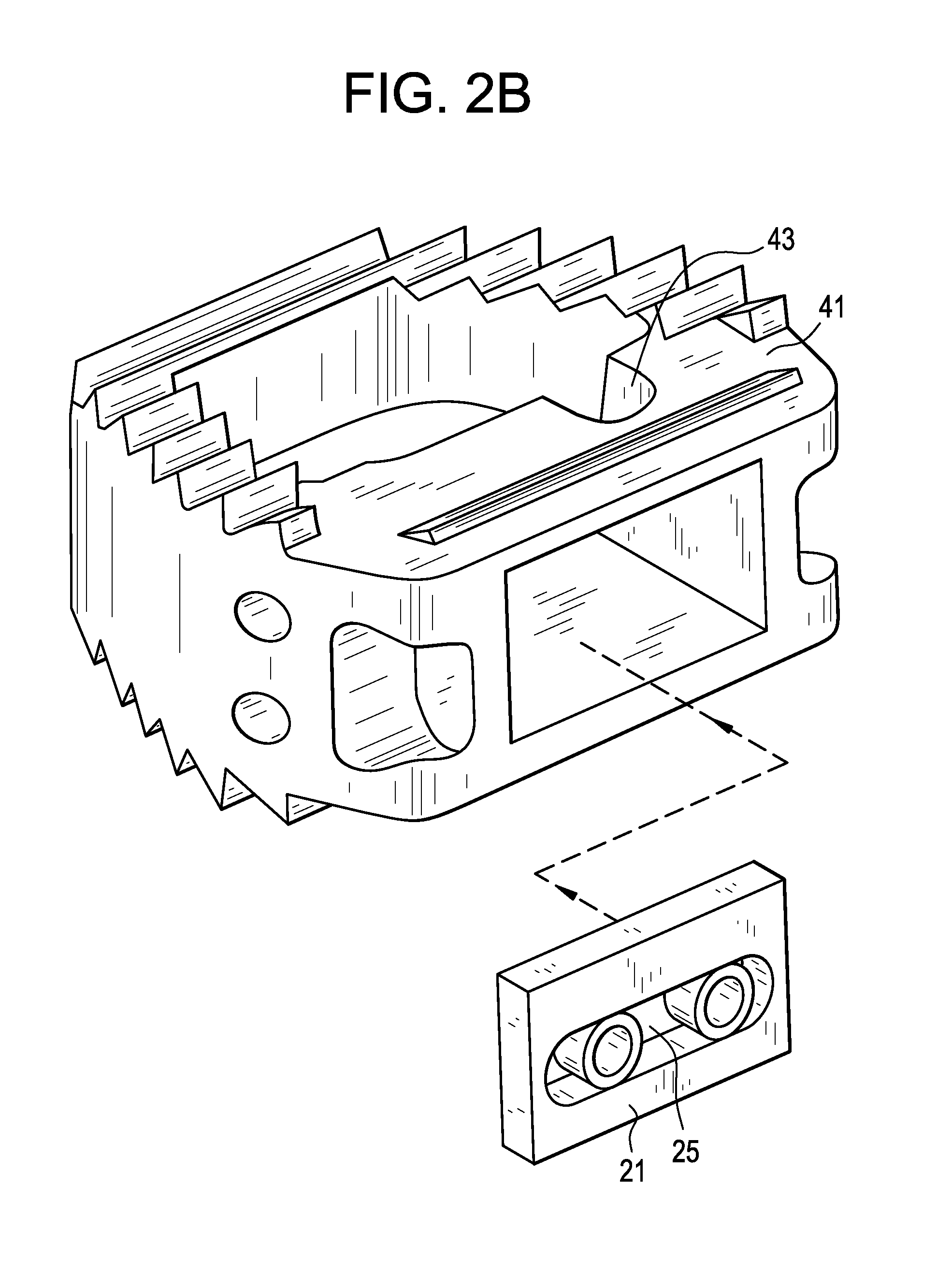
FIG. 2B shows an exploded version of FIG. 2a.
FIG. 2C discloses a non-circular washer.
FIG. 3 discloses a bone screw mating with the face plate to produce an angle .alpha. of between about 15 and 75 degrees.
DETAILED DESCRIPTION OF THE INVENTION
For the purpose of the present invention, a "front wall" includes a strur connecting the two side walls, but does not include the front faces of two unconnected sidewalls.
Now referring to FIGS. 1A-1C, there is provided an intervertebral fusion device comprising; a) a cage 1 comprising a front wall 3 having a first window 5 therethrough, a back wall 7, and two side walls 9 connecting the front and back walls, the front wall extending continuously between the two side walls, the four walls defining a perimeter and a single vertical throughhole 11, and b) a face plate 21 received in the window, attached to the front wall and substantially covering the first window.
FIG. 1A shows the cage without a faceplate. In this condition, graft material can be packed or injected through the window. FIG. 1B shows the combination of the cage having a faceplate attached therethrough. Bone screws (not shown) may be received in the pair of screwholes 23 of the faceplate in order to secure the device to the adjacent vertebral bodies, thereby preventing migration.
The device of the present invention can be suited for insertion into the cervical, thoracic or lumbar disc space. The particular device shown in FIG. 1A is best suited for insertion into the cervical disc space through an anterior approach. The perimeter of the cage of FIG. 1A substantially has the shape of a cervical disc space. In some embodiments, the cervical cage has a length (L) and width (W) such that the length is between about 50% and 150% of the width, more preferably between about 80% and 120% of the width. Preferably, the cage has teeth 13 extending from the upper 15 and lower 17 surfaces of the cage.
Now referring to FIG. 1D, in some embodiments, the peripheries of the faceplate and window having mating features that allow the faceplate to be inserted into the window, and then slightly shifted so that it cannot back out. IN FIG. 1 d, the faceplate has a length that is shorter than the corresponding window 5. The periphery of the faceplate has notches 53 that correspond to the protrusions 51 on the periphery of the window. These mating features allow the faceplate to be inserted into the window and past the protrusions. Once, the faceplate so inserted shifts (due to its shorter length), the faceplate may no longer easily be removed from the window.
Also as shown in FIG. 2A-2B, in some embodiments, the face plate has a horizontal slot 25 extending therethrough, with first 27 and second 29 washers received in the slot. The function of the washers is to receive first and second bone screws 101 that allow for fixation of the cage. The washers are adapted to be slidable in the slot, so that their positions may be infinitely adjusted to suit the desires of the surgeon. In some embodiments, as in FIG. 2C, at least one (and preferably both) of the washers 31 have a cam shape. This cam shape may provide to the washer a first dimension D1 and a second dimension D2, wherein D1 is greater than D2. This non-circular shape allows the washer to be first slid to an appropriate location within the slot and then turned 90 degrees in order to lock that position. In some embodiments, the washer may have a threaded receiving hole.
In some embodiments (not shown), the there may be three washers disposed in the slot, whereby the two outer washers receive bone fixation means (such as a bone screw) pointing in one direction and the middle washer receives a bone fixation means in the other direction.
In some embodiments (not shown), the there may be four washers disposed in the slot, whereby a first two alternating washers receive bone fixation means (such as a bone screw) pointing in one direction and the remaining two washers each receive a bone fixation means in the other direction.
Now referring to FIG. 2B, in some embodiments, the device comprises first and second screwholes, each screwhole adapted to receive a bone screw. In some of these embodiments, each screwhole is formed in both the plate and the cage. As in FIG. 2B, in some embodiments, each screwhole is at least partially open. In these open embodiments, the front wall comprises a top surface 41 and a bottom surface, wherein a portion 43 of the first screwhole formed in the cage opens at least partially onto the top surface of the cage, and wherein a portion of the second screwhole formed in the cage opens at least partially onto the bottom surface of the cage. The open nature of these allows for the use of larger bone screws within the same cage, thereby enhancing the fixation strength of the device. Lastly, there are preferably first and second bone screws (not shown) respectively received in the first and second screwholes.
In some embodiments, the front wall has a front surface, the face plate has a front surface, and the front surfaces are substantially co-planar. This produces the desirable zero-profile shape that reduces the chances of irritation of the great vessels that sit anterior to the device in the cervical spine.
In some embodiments, and now referring to FIG. 3, each bone screw 51 preferably mates with the face plate and cage to produce an angle .alpha. of between about 15 and 75 degrees.
The faceplate may be attached to the anterior wall of the cage by any conventional means. In some embodiments, the face plate is attached to the front wall by a hinge. In others, the faceplate forms a Morse taper with the window and is attached to the front wall by a press fit mechanism, thereby locking the faceplate in place.
The intervertebral fusion cage of the present invention may be manufactured from any biocompatible flexible material suitable for use in interbody fusion procedures. In some embodiments, the cage comprises a composite comprising 40-100% polyarylethyl ketone PAEK, and optionally 1-60% carbon fiber. Such a cage is radiolucent. Preferably, the polyarylethyl ketone PAEK is selected from the group consisting of polyetherether ketone PEEK, polyether ketone ketone PEKK, polyether ketone ether ketone ketone PEKEKK, and polyether ketone PEK. Preferably, cage is made from woven, long carbon fiber laminates. Preferably, the PAEK and carbon fiber are homogeneously mixed. In some embodiments, the composite consists essentially of PAEK and carbon fiber. In some embodiments, the composite comprises 60-80 wt % PAEK and 20-40 wt % carbon fiber, more preferably 65-75 wt % PAEK and 25-35 wt % carbon fiber. In some embodiments, the cage is made from materials used in carbon fibers cages marketed by DePuy Spine, Raynham, Mass., USA. In some embodiments, the composite is PEEK-OPTIMA.TM., available from Invibio of Greenville, N.C.
Typically, each of the faceplate and washer is made from a biocompatible metal in order to enhance the strength of the screw-receiving component. In some embodiments, the faceplate is made from a material selected from the group consisting of stainless steel, chromium-cobalt and a titanium alloy.
Typically, each screw is made from a biocompatible metal selected from the group consisting of stainless steel, chromium-cobalt and a titanium alloy.
In some embodiments, a screw is used disclosed as the fixation means for fixing the cage to the vertebral bodies. However, any conventional fixation means for fixing a cage to a vertebral body can be used.
In some embodiments, the fusion cage of the present invention is used to treat DDD and is placed within a disc space between adjacent vertebral bodies. In others, it is used in a corpectomy case, and replaces a vertebral body.
In some embodiments, after the cage of the present invention has been inserted into the disc space, the surgeon may place an endplate preparation instrument (such as a curette) through the anterior window of the cage and prepare the portion of the endplate not supported by bone. This method insures that not only is the endplate adequately prepared, but there remains an intact rim of cortical bone supporting the endplate.
In some embodiments, the device further comprises graft material disposed within the vertical throughole of the cage. In these embodiments, the graft is inserted by a method comprising: a) implanting the cage of the preent invention into an intervertebral disc space, b) inserting bone graft material through the first window of the implanted cage and into the vertical throughhole of the cage, and c) attaching a face plate to the front wall of the implanted cage to substantially cover the first window of the cage.
In some embodiments, the bone graft material is injected through the first window. In some embodiments, this bone graft material is flowable. In some embodiments, the flowable graft material may be HEALOS FX.TM., a flowable collagen-based material available from DePuy Spine of Raynham, Mass., USA.
In some embodiments, the bone graft material is packed into the vertical throughhole.
In some embodiments, the graft material may comprises a bone forming agent. In some embodiments, the bone forming agent is a growth factor. As used herein, the term "growth factor" encompasses any cellular product that modulates the growth or differentiation of other cells, particularly connective tissue progenitor cells. The growth factors that may be used in accordance with the present invention include, but are not limited to, members of the fibroblast growth factor family, including acidic and basic fibroblast growth factor (FGF-1 and FGF-2) and FGF-4; members of the platelet-derived growth factor (PDGF) family, including PDGF-AB, PDGF-BB and PDGF-AA; EGFs; VEGF; members of the insulin-like growth factor (IGF) family, including IGF-I and -II; the TGF-.beta. superfamily, including TGF-.beta.1, 2 and 3; osteoid-inducing factor (OIF), angiogenin(s); endothelins; hepatocyte growth factor and keratinocyte growth factor, members of the bone morphogenetic proteins (BMPs) BMP-1, BMP-3, BMP-2, OP-1, BMP-2A, BMP-2B, BMP-7 and BMP-14, including HBGF-1 and HBGF-2; growth differentiation factors (GDFs), members of the hedgehog family of proteins, including indian, sonic and desert hedgehog ADMP-1; bone-forming members of the interleukin (IL) family; rhGDF-5; and members of the colony-stimulating factor (CSF) family, including CSF-1, G-CSF, and GM-CSF; and isoforms thereof.
In some embodiments, platelet concentrate is provided as the bone forming agent. In one embodiment, the growth factors released by the platelets are present in an amount at least two-fold (e.g. four-fold) greater than the amount found in the blood from which the platelets were taken. In some embodiments, the platelet concentrate is autologous. In some embodiments, the platelet concentrate is platelet rich plasma (PRP). PRP is advantageous because it contains growth factors that can restimulate the growth of the bone, and because its fibrin matrix provides a suitable scaffold for new tissue growth.
In some embodiments, the bone forming agent comprises an effective amount of a bone morphogenic protein (BMP). BMPs beneficially increasing bone formation by promoting the differentiation of mesenchymal stem cells (MSCs) into osteoblasts and their proliferation.
In some embodiments, between about 1 ng and about 10 mg of BMP are administered into the target disc space. In some embodiments, between about 1 microgram (.mu.g) and about 1 mg of BMP are administered into the target disc space.
In many preferred embodiments, the bone forming agent is a porous matrix, and is preferably injectable.
The porous matrix of the present invention may contain porous or semi-porous collagen, extracellular matrices, metals (such as Ti, Ti64, CoCr, and stainless steel), polymers (such as PEEK, polyethylene, polypropylene, and PET) resorbable polymers (such as PLA, PDA, PEO, PEG, PVA, and capralactides), bone substitutes (such as TCP, HA, and CaP), autograft, allograft, xenograft, and/or blends thereof. Matrices may be orientated to enable flow from bony attachment locations to the aspiration port. Matrices may be layered with varying densities, pore structures, materials to enable increase stem filter at desired locations via density, pore size, affinity, as well as fluid flow control (laminar, turbilant, and/or tortuous path).
In some embodiments, the porous matrix is a mineral. In one embodiment, this mineral comprises calcium and phosphorus. In some embodiments, the mineral is selected from the group consisting of calcium phosphate, tricalcium phosphate and hydroxyapatite. In one embodiment, the average porosity of the matrix is between about 20 and about 500 .mu.m, for example, between about 50 and about 250 .mu.m. In yet other embodiments of the present invention, in situ porosity is produced in the injected matrix to produce a porous scaffold in the interbody space. Once the in situ porosity is produced in the space, the surgeon can inject other therapeutic compounds into the porosity, thereby treating the surrounding tissues and enhancing the remodeling process of the target tissue.
In some embodiments, the mineral is administered in a granule form. It is believed that the administration of granular minerals promotes the formation of the bone growth around the minerals such that osteointegration occurs.
In some embodiments, the mineral is administered in a settable-paste form. In this condition, the paste sets up in vivo, and thereby immediately imparts post-treatment mechanical support to the interbody space.
In another embodiment, the treatment is delivered via injectable absorbable or non-absorbable cement to the target space. The treatment is formulated using bioabsorbable macro-sphere technologies, such that it will allow the release of the bone forming agent. The cement will provide the initial stability required to treat pain in target tissues. These tissues include, but are not limited to, hips, knee, vertebral body and iliac crest. In some embodiments, the cement is selected from the group consisting of calcium phosphate, tricalcium phosphate and hydroxyapatite. In other embodiments, the cement is any hard biocompatible cement, including PMMA, processed autogenous and allograft bone. Hydroxylapatite is a preferred cement because of its strength and biological profile. Tricalcium phosphate may also be used alone or in combination with hydroxylapatite, particularly if some degree of resorption is desired in the cement.
In some embodiments, the porous matrix comprises a resorbable polymeric material.
In some embodiments, the bone forming agent comprises an injectable precursor fluid that produces the in situ formation of a mineralized collagen composite. In some embodiments, the injectable precursor fluid comprises: a) a first formulation comprising an acid-soluble type I collagen solution (preferably between about 1 mg/ml and about 7 mg/ml collagen) and b) a second formulation comprising liposomes containing calcium and phosphate.
Combining the acid-soluble collagen solution with the calcium- and phosphate-loaded liposomes results in a liposome/collagen precursor fluid, which, when heated from room temperature to 37.degree. C., forms a mineralized collagen gel.
In some embodiments, the liposomes are loaded with dipalmitoylphosphatidylcholine (90 mol %) and dimyristoyl phosphatidylcholine (10 mol %). These liposomes are stable at room temperature but form calcium phosphate mineral when heated above 35.degree. C., a consequence of the release of entrapped salts at the lipid chain melting transition. One such technology is disclosed in Pederson, Biomaterials 24: 4881-4890 (2003), the specification of which is incorporated herein by reference in its entirety.
Alternatively, the in situ mineralization of collagen could be achieved by an increase in temperature achieved by other types of reactions including, but not limited to, chemical, enzymatic, magnetic, electric, photo- or nuclear. Suitable sources thereof include light, chemical reaction, enzymatically controlled reaction and an electric wire embedded in the material. To further elucidate the electric wire approach, a wire can first be embedded in the space, heated to create the calcium deposition, and then withdrawn. In some embodiments, this wire may be a shape memory such as nitinol that can form the shape. Alternatively, an electrically-conducting polymer can be selected as the temperature raising element. This polymer is heated to form the collagen, and is then subject to disintegration and resorption in situ, thereby providing space adjacent the mineralized collagen for the bone to form.
In some embodiments, the osteoconductive material comprises calcium and phosphorus. In some embodiments, the osteoconductive material comprises hydroxyapatite. In some embodiments, the osteoconductive material comprises collagen. In some embodiments, the osteoconductive material is in a particulate form.
Specific matrices may be incorporated into the device to provide load bearing qualities, enable directional bone formation, and/or control density of regenerated bone (cortical vs cancellous) or enable cell formation for soft tissue attachment. Nanotubes or nanocrystals can be orientated in a generally axial direction to provide for load bearing abilities as well as capillary wicking of vascular flow to further enhance directional bone formation. Biocompatible nanotubes can currently be produced from either carbon or titanium or bone substitutes including Ca, HA, and TCP.
In one embodiment, the bone forming agent is a plurality of viable ex vivo osteoprogenitor cells. Such viable cells, introduced into the interbody space, have the capability of at least partially supplementing the in situ drawn stem cells in the generation of new bone for the interbody space.
In some embodiments, these cells are obtained from another human individual (allograft), while in other embodiments, the cells are obtained from the same individual (autograft). In some embodiments, the cells are taken from bone tissue, while in others, the cells are taken from a non-bone tissue (and may, for example, be mesenchymal stem cells, chondrocytes or fibroblasts). In others, autograft osteocytes (such as from the knee, hip, shoulder, finger or ear) may be used.
In one embodiment, when viable ex vivo cells are selected as an additional therapeutic agent or substance, the viable cells comprise mesenchymal stem cells (MSCs). MSCs provide a special advantage for administration into the interbody space because it is believed that they can more readily survive the relatively harsh environment present in the space; that they have a desirable level of plasticity; and that they have the ability to proliferate and differentiate into the desired cells.
In some embodiments, the mesenchymal stem cells are obtained from bone marrow, such as autologous bone marrow. In others, the mesenchymal stem cells are obtained from adipose tissue, preferably autologous adipose tissue.
In some embodiments, the mesenchymal stem cells injected into the interbody space are provided in an unconcentrated form, e.g., from fresh bone marrow. In others, they are provided in a concentrated form. When provided in concentrated form, they can be uncultured. Uncultured, concentrated MSCs can be readily obtained by centrifugation, filtration, or immuno-absorption. When filtration is selected, the methods disclosed in U.S. Pat. No. 6,049,026 ("Muschler"), the specification of which is incorporated herein by reference in its entirety, can be used. In some embodiments, the matrix used to filter and concentrate the MSCs is also administered into the interbody space.
In some embodiments, bone cells (which may be from either an allogeneic or an autologous source) or mesenchymal stem cells, may be genetically modified to produce an osteoinductive bone anabolic agent which could be chosen from the list of growth factors named herein. The production of these osteopromotive agents may lead to bone growth.
Recent work has shown that plasmid DNA will not elicit an inflammatory response as does the use of viral vectors. Genes encoding bone (anabolic) agents such as BMP may be efficacious if injected into the uncoupled resorbing bone. In addition, overexpression of any of the growth factors provided herein or other agents which would limit local osteoclast activity would have positive effects on bone growth. In one embodiment, the plasmid contains the genetic code for human TGF-.beta. or erythropoietin (EPO).
Accordingly, in some embodiments, the additional therapeutic agent is selected from the group consisting of viable cells and plasmid DNA.
A matrix may be made from hydrogels or may incorporate a hydrogel as component of the final structure. A hydrogel may be used to expand and enhance filling, improve handling characteristics or increase vacuum pressure. The increased vacuum pressure may be used to determine adequate hydration/stem cell filtration.
In all cases, excess bone marrow aspirate can be collected and mixed with added graft extenders including collagen like the HEALOS.TM. and HEALOS FX.TM., each of which is available from DePuy Spine Inc, Raynham, Mass., USA.
Although the present invention has been described with reference to its preferred embodiments, those skillful in the art will recognize changes that may be made in form and structure which do not depart from the spirit of the invention.
* * * * *
D00000
D00001
D00002
D00003
D00004
D00005
D00006
D00007
D00008
XML
uspto.report is an independent third-party trademark research tool that is not affiliated, endorsed, or sponsored by the United States Patent and Trademark Office (USPTO) or any other governmental organization. The information provided by uspto.report is based on publicly available data at the time of writing and is intended for informational purposes only.
While we strive to provide accurate and up-to-date information, we do not guarantee the accuracy, completeness, reliability, or suitability of the information displayed on this site. The use of this site is at your own risk. Any reliance you place on such information is therefore strictly at your own risk.
All official trademark data, including owner information, should be verified by visiting the official USPTO website at www.uspto.gov. This site is not intended to replace professional legal advice and should not be used as a substitute for consulting with a legal professional who is knowledgeable about trademark law.