Integrity testing method and apparatus for delivering vapor to the uterus
Chee , et al. Ja
U.S. patent number 10,179,019 [Application Number 14/719,037] was granted by the patent office on 2019-01-15 for integrity testing method and apparatus for delivering vapor to the uterus. This patent grant is currently assigned to AEGEA MEDICAL INC.. The grantee listed for this patent is AEGEA MEDICAL INC.. Invention is credited to Steven Robert Bacich, Uriel Hiram Chee, Donnell William Gurskis, Hugh Edward Magen, Robert Bilgor Peliks.

| United States Patent | 10,179,019 |
| Chee , et al. | January 15, 2019 |
Integrity testing method and apparatus for delivering vapor to the uterus
Abstract
A method and system of providing therapy to a patient's uterus is provided, which can include any number of features. The method can include the steps of inserting a uterine device into the uterus and performing a uterine integrity test to determine that the uterus is intact and not perforated. If it is determined that the uterus is not perforated, a patency test can be performed to determine that the uterine device is not clogged or embedded in tissue. If the uterus is intact and the device is not clogged or embedded in tissue, the uterus can be treated with the uterine device, e.g., uterine ablation. Systems for performing these methods are also disclosed.
| Inventors: | Chee; Uriel Hiram (Redwood City, CA), Peliks; Robert Bilgor (Redwood City, CA), Magen; Hugh Edward (San Francisco, CA), Gurskis; Donnell William (Belmont, CA), Bacich; Steven Robert (Half Moon Bay, CA) | ||||||||||
|---|---|---|---|---|---|---|---|---|---|---|---|
| Applicant: |
|
||||||||||
| Assignee: | AEGEA MEDICAL INC. (Redwood
City, CA) |
||||||||||
| Family ID: | 54554775 | ||||||||||
| Appl. No.: | 14/719,037 | ||||||||||
| Filed: | May 21, 2015 |
Prior Publication Data
| Document Identifier | Publication Date | |
|---|---|---|
| US 20150335373 A1 | Nov 26, 2015 | |
Related U.S. Patent Documents
| Application Number | Filing Date | Patent Number | Issue Date | ||
|---|---|---|---|---|---|
| 62002070 | May 22, 2014 | ||||
| Current U.S. Class: | 1/1 |
| Current CPC Class: | A61B 17/42 (20130101); A61M 25/04 (20130101); A61B 5/035 (20130101); A61B 5/6847 (20130101); A61B 18/04 (20130101); A61B 5/4325 (20130101); A61M 31/00 (20130101); A61M 2210/1433 (20130101); A61M 2025/1052 (20130101); A61B 2017/00557 (20130101); A61B 2018/00559 (20130101); A61B 2090/0807 (20160201); A61B 2017/4216 (20130101); A61B 2017/00115 (20130101); A61B 2017/00022 (20130101); A61B 2090/064 (20160201) |
| Current International Class: | A61B 5/00 (20060101); A61B 18/04 (20060101); A61B 17/42 (20060101); A61B 5/03 (20060101); A61B 18/00 (20060101); A61B 17/00 (20060101); A61B 90/00 (20160101) |
References Cited [Referenced By]
U.S. Patent Documents
| 408899 | August 1889 | Small |
| 697181 | April 1902 | Smith |
| 1719750 | July 1929 | Bridge et al. |
| 3818913 | June 1974 | Wallach |
| 3871374 | March 1975 | Bolduc et al. |
| 3880168 | April 1975 | Berman |
| 3924628 | December 1975 | Droegemueller et al. |
| 3930505 | January 1976 | Wallach |
| 4083077 | April 1978 | Knight et al. |
| 4447227 | May 1984 | Kotsanis |
| 4672962 | June 1987 | Hershenson |
| 4682596 | July 1987 | Bales et al. |
| 4748979 | June 1988 | Hershenson |
| 4773410 | September 1988 | Blackmer et al. |
| 4793352 | December 1988 | Eichenlaub |
| 4872920 | October 1989 | Flynn et al. |
| 4898574 | February 1990 | Uchiyama et al. |
| 4915113 | April 1990 | Holman |
| 4941475 | July 1990 | Williams et al. |
| 4950266 | August 1990 | Sinofsky |
| 4976711 | December 1990 | Parins et al. |
| 4985027 | January 1991 | Dressel |
| 5006119 | April 1991 | Acker et al. |
| 5011566 | April 1991 | Hoffman |
| 5045056 | September 1991 | Behl |
| 5078736 | January 1992 | Behl |
| 5084043 | January 1992 | Hertzmann et al. |
| 5084044 | January 1992 | Quint |
| 5102410 | April 1992 | Dressel |
| 5112328 | May 1992 | Taboada et al. |
| 5122138 | June 1992 | Manwaring |
| 5158536 | October 1992 | Sekins et al. |
| 5162374 | November 1992 | Mulieri et al. |
| 5190539 | March 1993 | Fletcher et al. |
| 5217459 | June 1993 | Kamerling |
| 5217465 | June 1993 | Steppe |
| 5242474 | September 1993 | Herbst et al. |
| 5246436 | September 1993 | Rowe |
| 5263951 | November 1993 | Spears et al. |
| 5277201 | January 1994 | Stern |
| 5277696 | January 1994 | Hagen |
| 5306274 | April 1994 | Long |
| 5318014 | June 1994 | Carter |
| 5331947 | July 1994 | Shturman |
| 5334190 | August 1994 | Seiler |
| 5344397 | September 1994 | Heaven et al. |
| 5348551 | September 1994 | Spears et al. |
| 5352512 | October 1994 | Hoffman |
| 5417686 | May 1995 | Peterson et al. |
| 5424620 | June 1995 | Cheon et al. |
| 5433708 | July 1995 | Nichols et al. |
| 5433739 | July 1995 | Sluijter et al. |
| 5437629 | August 1995 | Goldrath |
| 5443470 | August 1995 | Stern et al. |
| 5445168 | August 1995 | Krebs |
| 5449380 | September 1995 | Chin |
| 5451208 | September 1995 | Goldrath |
| 5462521 | October 1995 | Brucker et al. |
| 5500012 | March 1996 | Brucker et al. |
| 5503638 | April 1996 | Cooper et al. |
| 5505730 | April 1996 | Edwards |
| 5524620 | June 1996 | Rosenschein |
| 5529076 | June 1996 | Schachar |
| 5540658 | July 1996 | Evans et al. |
| 5542928 | August 1996 | Evans et al. |
| 5554172 | September 1996 | Horner et al. |
| 5562608 | October 1996 | Sekins et al. |
| 5562720 | October 1996 | Stern et al. |
| 5584872 | December 1996 | LaFontaine et al. |
| 5591157 | January 1997 | Hennings et al. |
| 5616120 | April 1997 | Andrew et al. |
| 5620440 | April 1997 | Heckele et al. |
| 5647871 | July 1997 | Levine et al. |
| 5653692 | August 1997 | Masterson et al. |
| 5662671 | September 1997 | Barbut et al. |
| 5665074 | September 1997 | Kelly |
| 5669907 | September 1997 | Platt et al. |
| 5674191 | October 1997 | Edwards et al. |
| 5681282 | October 1997 | Eggers et al. |
| 5683366 | November 1997 | Eggers et al. |
| 5688267 | November 1997 | Panescu et al. |
| 5695507 | December 1997 | Auth et al. |
| 5697281 | December 1997 | Eggers et al. |
| 5697536 | December 1997 | Eggers et al. |
| 5697882 | December 1997 | Eggers et al. |
| 5697909 | December 1997 | Eggers et al. |
| 5700262 | December 1997 | Acosta et al. |
| 5707352 | January 1998 | Sekins et al. |
| 5730719 | March 1998 | Edwards |
| 5735811 | April 1998 | Brisken |
| 5741247 | April 1998 | Rizoiu et al. |
| 5741248 | April 1998 | Stern et al. |
| 5743870 | April 1998 | Edwards |
| 5752965 | May 1998 | Francis et al. |
| 5754717 | May 1998 | Esch |
| 5755753 | May 1998 | Knowlton |
| 5769880 | June 1998 | Truckai et al. |
| 5782914 | July 1998 | Schankereli |
| 5785521 | July 1998 | Rizoiu et al. |
| 5800379 | September 1998 | Edwards |
| 5800482 | September 1998 | Pomeranz et al. |
| 5800493 | September 1998 | Stevens et al. |
| 5810764 | September 1998 | Eggers et al. |
| 5820580 | October 1998 | Edwards et al. |
| 5824703 | October 1998 | Clark |
| 5827268 | October 1998 | Laufer |
| 5836896 | November 1998 | Rosenschein |
| 5836906 | November 1998 | Edwards |
| 5843019 | December 1998 | Eggers et al. |
| 5871469 | February 1999 | Eggers et al. |
| 5873855 | February 1999 | Eggers et al. |
| 5879329 | March 1999 | Ginsburg |
| 5885243 | March 1999 | Capetan et al. |
| 5888198 | March 1999 | Eggers et al. |
| 5891094 | April 1999 | Masterson et al. |
| 5891095 | April 1999 | Eggers et al. |
| 5891134 | April 1999 | Goble et al. |
| 5891457 | April 1999 | Neuwirth |
| 5902272 | May 1999 | Eggers et al. |
| 5911734 | June 1999 | Tsugita et al. |
| 5913856 | June 1999 | Chia et al. |
| 5938660 | August 1999 | Swartz et al. |
| 5944686 | August 1999 | Patterson et al. |
| 5944715 | August 1999 | Goble et al. |
| 5957919 | September 1999 | Laufer |
| 5964752 | October 1999 | Stone |
| 5968037 | October 1999 | Rizoiu et al. |
| 5980504 | November 1999 | Sharkey et al. |
| 5986662 | November 1999 | Argiro et al. |
| 5989212 | November 1999 | Sussman et al. |
| 5989249 | November 1999 | Kirwan |
| 5989445 | November 1999 | Wise et al. |
| 5997499 | December 1999 | Sussman et al. |
| 6004509 | December 1999 | Dey et al. |
| 6015406 | January 2000 | Goble et al. |
| 6024095 | February 2000 | Stanley |
| 6024733 | February 2000 | Eggers et al. |
| 6027501 | February 2000 | Goble et al. |
| 6032077 | February 2000 | Pomeranz |
| 6045532 | April 2000 | Eggers et al. |
| 6045549 | April 2000 | Smethers et al. |
| 6047700 | April 2000 | Eggers et al. |
| 6053172 | April 2000 | Hovda et al. |
| 6053909 | April 2000 | Shadduck |
| 6056746 | May 2000 | Goble et al. |
| 6057689 | May 2000 | Saadat |
| 6059011 | May 2000 | Giolo |
| 6063079 | May 2000 | Hovda et al. |
| 6063081 | May 2000 | Mulier et al. |
| 6066134 | May 2000 | Eggers et al. |
| 6066139 | May 2000 | Ryan et al. |
| 6080128 | June 2000 | Sussman et al. |
| 6080151 | June 2000 | Swartz et al. |
| 6083255 | July 2000 | Laufer et al. |
| 6086585 | July 2000 | Hovda et al. |
| 6095149 | August 2000 | Sharkey et al. |
| 6099251 | August 2000 | LaFleur |
| 6102046 | August 2000 | Weinstein et al. |
| 6102885 | August 2000 | Bass |
| 6105581 | August 2000 | Eggers et al. |
| 6106516 | August 2000 | Massengill |
| 6109268 | August 2000 | Thapliyal et al. |
| 6113597 | September 2000 | Eggers et al. |
| 6113722 | September 2000 | Hoffman et al. |
| 6117109 | September 2000 | Eggers et al. |
| 6126682 | October 2000 | Sharkey et al. |
| 6130671 | October 2000 | Argiro |
| 6139571 | October 2000 | Fuller et al. |
| 6149620 | November 2000 | Baker et al. |
| 6156036 | December 2000 | Sussman et al. |
| 6159160 | December 2000 | Hsei et al. |
| 6159194 | December 2000 | Eggers et al. |
| 6159207 | December 2000 | Yoon |
| 6159208 | December 2000 | Hovda et al. |
| 6162232 | December 2000 | Shadduck |
| 6174308 | January 2001 | Goble et al. |
| 6179805 | January 2001 | Sussman et al. |
| 6179824 | January 2001 | Eggers et al. |
| 6179836 | January 2001 | Eggers et al. |
| 6183469 | February 2001 | Thapliyal et al. |
| 6190381 | February 2001 | Olsen et al. |
| 6194066 | February 2001 | Hoffman |
| 6196989 | March 2001 | Padget et al. |
| 6200333 | March 2001 | Laufer |
| 6203542 | March 2001 | Ellsberry et al. |
| 6210402 | April 2001 | Olsen et al. |
| 6210404 | April 2001 | Shadduck |
| 6210405 | April 2001 | Goble et al. |
| 6219059 | April 2001 | Argiro |
| 6224592 | May 2001 | Eggers et al. |
| 6228078 | May 2001 | Eggers et al. |
| 6228081 | May 2001 | Goble |
| 6228082 | May 2001 | Baker et al. |
| 6231567 | May 2001 | Rizoiu et al. |
| 6235020 | May 2001 | Cheng et al. |
| 6238391 | May 2001 | Olsen et al. |
| 6254597 | July 2001 | Rizoiu et al. |
| 6254600 | July 2001 | Willink et al. |
| 6261286 | July 2001 | Goble et al. |
| 6261311 | July 2001 | Sharkey et al. |
| 6264650 | July 2001 | Hovda et al. |
| 6264651 | July 2001 | Underwood et al. |
| 6264652 | July 2001 | Eggers et al. |
| 6277112 | August 2001 | Underwood et al. |
| 6277114 | August 2001 | Bullivant et al. |
| 6283910 | September 2001 | Bradshaw et al. |
| 6283961 | September 2001 | Underwood et al. |
| 6283989 | September 2001 | Laufer et al. |
| 6290715 | September 2001 | Sharkey et al. |
| 6293942 | September 2001 | Goble et al. |
| 6296636 | October 2001 | Cheng et al. |
| 6296638 | October 2001 | Davison et al. |
| 6299633 | October 2001 | Laufer |
| 6300150 | October 2001 | Venkatasubramanian |
| 6306129 | October 2001 | Little et al. |
| 6306134 | October 2001 | Goble et al. |
| 6309387 | October 2001 | Eggers et al. |
| 6312408 | November 2001 | Eggers et al. |
| 6312474 | November 2001 | Francis et al. |
| 6315755 | November 2001 | Sussman |
| 6319221 | November 2001 | Savage et al. |
| 6322549 | November 2001 | Eggers et al. |
| 6327505 | December 2001 | Medhkour et al. |
| 6331171 | December 2001 | Cohen |
| 6355032 | March 2002 | Hovda et al. |
| 6361531 | March 2002 | Hissong |
| 6363937 | April 2002 | Hovda et al. |
| 6364877 | April 2002 | Goble et al. |
| 6375635 | April 2002 | Moutafis |
| 6379350 | April 2002 | Sharkey et al. |
| 6379351 | April 2002 | Thapliyal et al. |
| 6391025 | May 2002 | Weinstein et al. |
| 6394949 | May 2002 | Crowley et al. |
| 6394996 | May 2002 | Lawrence et al. |
| 6398759 | June 2002 | Sussman et al. |
| 6398775 | June 2002 | Perkins et al. |
| 6409699 | June 2002 | Ash |
| 6409723 | June 2002 | Edwards |
| 6416507 | July 2002 | Eggers et al. |
| 6416508 | July 2002 | Eggers et al. |
| 6416509 | July 2002 | Goble et al. |
| 6432103 | August 2002 | Ellsberry et al. |
| 6440089 | August 2002 | Shine |
| 6458231 | October 2002 | Wapner et al. |
| 6461350 | October 2002 | Underwood et al. |
| 6461354 | October 2002 | Olsen et al. |
| 6464694 | October 2002 | Massengill |
| 6464695 | October 2002 | Hovda et al. |
| 6468270 | October 2002 | Hovda et al. |
| 6468274 | October 2002 | Alleyne et al. |
| 6468313 | October 2002 | Claeson et al. |
| 6475215 | November 2002 | Tanrisever |
| 6482201 | November 2002 | Olsen et al. |
| 6488673 | December 2002 | Laufer et al. |
| 6493589 | December 2002 | Medhkour et al. |
| 6500173 | December 2002 | Underwood et al. |
| 6508816 | January 2003 | Shadduck |
| 6510854 | January 2003 | Goble |
| 6517533 | February 2003 | Swaminathan |
| 6522930 | February 2003 | Schaer et al. |
| 6527761 | March 2003 | Soltesz et al. |
| 6527766 | March 2003 | Bair |
| 6540741 | April 2003 | Underwood et al. |
| 6544211 | April 2003 | Andrew et al. |
| 6544261 | April 2003 | Ellsberry et al. |
| 6547784 | April 2003 | Thompson et al. |
| 6551271 | April 2003 | Nguyen |
| 6551274 | April 2003 | Heiner |
| 6554780 | April 2003 | Sampson et al. |
| 6557559 | May 2003 | Eggers et al. |
| 6558379 | May 2003 | Batchelor et al. |
| 6565561 | May 2003 | Goble et al. |
| 6569146 | May 2003 | Werner et al. |
| 6575929 | June 2003 | Sussman et al. |
| 6575933 | June 2003 | Wittenberger et al. |
| 6575968 | June 2003 | Eggers et al. |
| 6579270 | June 2003 | Sussman et al. |
| 6582423 | June 2003 | Thapliyal et al. |
| 6585639 | July 2003 | Kotmel et al. |
| 6588613 | July 2003 | Pechenik et al. |
| 6589201 | July 2003 | Sussman et al. |
| 6589237 | July 2003 | Woloszko et al. |
| 6592594 | July 2003 | Rimbaugh et al. |
| 6595990 | July 2003 | Weinstein et al. |
| 6599311 | July 2003 | Biggs et al. |
| 6602248 | August 2003 | Sharps et al. |
| 6610043 | August 2003 | Ingenito |
| 6620155 | September 2003 | Underwood et al. |
| 6623444 | September 2003 | Babaev |
| 6626855 | September 2003 | Weng et al. |
| 6629974 | October 2003 | Penny et al. |
| 6632193 | October 2003 | Davison et al. |
| 6632220 | October 2003 | Eggers et al. |
| 6634363 | October 2003 | Danek et al. |
| 6653525 | November 2003 | Ingenito et al. |
| 6669685 | December 2003 | Rizoiu et al. |
| 6669694 | December 2003 | Shadduck |
| 6676628 | January 2004 | Sussman et al. |
| 6676629 | January 2004 | Andrew et al. |
| 6679264 | January 2004 | Deem et al. |
| 6679879 | January 2004 | Shadduck |
| 6692494 | February 2004 | Cooper et al. |
| 6695839 | February 2004 | Sharkey et al. |
| 6699212 | March 2004 | Kadziauskas et al. |
| 6699244 | March 2004 | Carranza et al. |
| 6708056 | March 2004 | Duchon et al. |
| 6712811 | March 2004 | Underwood et al. |
| 6712812 | March 2004 | Roschak et al. |
| 6719754 | April 2004 | Underwood et al. |
| 6726684 | April 2004 | Woloszko et al. |
| 6726708 | April 2004 | Lasheras |
| 6746447 | June 2004 | Davison et al. |
| 6749604 | June 2004 | Eggers et al. |
| 6755794 | June 2004 | Soukup |
| 6758846 | July 2004 | Goble et al. |
| 6763836 | July 2004 | Tasto et al. |
| 6766202 | July 2004 | Underwood et al. |
| 6770070 | August 2004 | Balbierz |
| 6770071 | August 2004 | Woloszko et al. |
| 6772012 | August 2004 | Ricart et al. |
| 6773431 | August 2004 | Eggers et al. |
| 6776765 | August 2004 | Soukup et al. |
| 6780180 | August 2004 | Goble et al. |
| 6805130 | October 2004 | Tasto et al. |
| 6813520 | November 2004 | Truckai et al. |
| 6832996 | December 2004 | Woloszko et al. |
| 6837884 | January 2005 | Woloszko |
| 6837887 | January 2005 | Woloszko et al. |
| 6837888 | January 2005 | Ciarrocca et al. |
| 6852108 | February 2005 | Barry et al. |
| 6860847 | March 2005 | Alferness et al. |
| 6875194 | April 2005 | MacKool |
| 6896672 | May 2005 | Eggers et al. |
| 6896674 | May 2005 | Woioszko et al. |
| 6896675 | May 2005 | Leung et al. |
| 6896690 | May 2005 | Lambrecht et al. |
| 6901927 | June 2005 | Deem et al. |
| 6904909 | June 2005 | Andreas et al. |
| 6907881 | June 2005 | Suki et al. |
| 6911028 | June 2005 | Shadduck |
| 6915806 | July 2005 | Pacek et al. |
| 6918903 | July 2005 | Bass |
| 6921385 | July 2005 | Clements et al. |
| 6929640 | August 2005 | Underwood et al. |
| 6929642 | August 2005 | Xiao et al. |
| 6949096 | September 2005 | Davison et al. |
| 6955675 | October 2005 | Jain |
| 6960204 | November 2005 | Eggers et al. |
| 6962584 | November 2005 | Stone et al. |
| 6972014 | December 2005 | Eum et al. |
| 6978174 | December 2005 | Gelfand et al. |
| 6986769 | January 2006 | Nelson et al. |
| 6991028 | January 2006 | Comeaux et al. |
| 6991631 | January 2006 | Woloszko et al. |
| 7004940 | February 2006 | Ryan et al. |
| 7004941 | February 2006 | Tvinnereim et al. |
| 7022088 | April 2006 | Keast et al. |
| 7031504 | April 2006 | Argiro et al. |
| 7070596 | July 2006 | Woloszko et al. |
| 7083612 | August 2006 | Littrup et al. |
| 7094215 | August 2006 | Davison et al. |
| 7094249 | August 2006 | Broome et al. |
| 7101367 | September 2006 | Xiao et al. |
| 7104986 | September 2006 | Hovda et al. |
| 7105007 | September 2006 | Hibler |
| RE39358 | October 2006 | Goble |
| 7128748 | October 2006 | Mooradian et al. |
| 7131969 | November 2006 | Hovda et al. |
| 7136064 | November 2006 | Zuiderveld |
| 7144402 | December 2006 | Kuester |
| 7144588 | December 2006 | Oray et al. |
| 7162303 | January 2007 | Levin et al. |
| 7169143 | January 2007 | Eggers et al. |
| 7179255 | February 2007 | Lettice et al. |
| 7186234 | March 2007 | Dahla et al. |
| 7192400 | March 2007 | Campbell et al. |
| 7192428 | March 2007 | Eggers et al. |
| 7201750 | April 2007 | Eggers et al. |
| 7217268 | May 2007 | Eggers et al. |
| 7233820 | June 2007 | Gilboa |
| 7235070 | June 2007 | Vanney |
| 7241293 | July 2007 | Davison |
| 7270658 | September 2007 | Woloszko et al. |
| 7270659 | September 2007 | Ricart et al. |
| 7270661 | September 2007 | Dahla et al. |
| 7276063 | October 2007 | Davison et al. |
| 7297143 | November 2007 | Woloszko et al. |
| 7297145 | November 2007 | Woloszko et al. |
| 7311708 | December 2007 | McClurken |
| 7320325 | January 2008 | Duchon et al. |
| 7335195 | February 2008 | Mehier |
| 7347859 | March 2008 | Garabedian et al. |
| 7524315 | April 2009 | Blott et al. |
| 7585295 | September 2009 | Ben-Nun |
| 7617005 | November 2009 | Demarais et al. |
| 7620451 | November 2009 | Demarais et al. |
| 7653438 | January 2010 | Deem et al. |
| 7756583 | July 2010 | Demarais et al. |
| 7815616 | October 2010 | Boehringer et al. |
| 7815646 | October 2010 | Hart |
| 7853333 | December 2010 | Demarais |
| 7873417 | January 2011 | Demarais et al. |
| 7937143 | May 2011 | Demarais et al. |
| 7993323 | August 2011 | Barry et al. |
| 8131371 | March 2012 | Demarals et al. |
| 8145316 | March 2012 | Deem et al. |
| 8145317 | March 2012 | Demarais et al. |
| 8150519 | April 2012 | Demarais et al. |
| 8150520 | April 2012 | Demarais et al. |
| 8175711 | May 2012 | Demarais et al. |
| 8192424 | June 2012 | Woloszko |
| 8197470 | June 2012 | Sharkey et al. |
| 8216217 | July 2012 | Sharkey et al. |
| 8221401 | July 2012 | Sharkey et al. |
| 8221403 | July 2012 | Sharkey et al. |
| 8313485 | November 2012 | Shadduck |
| 8574226 | November 2013 | Shadduck |
| 8579888 | November 2013 | Hoey et al. |
| 8579892 | November 2013 | Hoey et al. |
| 8585645 | November 2013 | Barry et al. |
| 8585692 | November 2013 | Shadduck et al. |
| 8801702 | August 2014 | Hoey et al. |
| 8900223 | December 2014 | Shadduck |
| 9662060 | May 2017 | Peliks |
| 9907599 | March 2018 | Hoey et al. |
| 2002/0007180 | January 2002 | Wittenberger et al. |
| 2002/0013601 | January 2002 | Nobles et al. |
| 2002/0019627 | February 2002 | Maguire et al. |
| 2002/0077516 | June 2002 | Flanigan |
| 2002/0078956 | June 2002 | Sharpe et al. |
| 2002/0111386 | August 2002 | Sekins et al. |
| 2002/0128638 | September 2002 | Chauvet et al. |
| 2002/0133147 | September 2002 | Marchitto et al. |
| 2002/0151917 | October 2002 | Barry |
| 2002/0161326 | October 2002 | Sussman et al. |
| 2002/0173815 | November 2002 | Hogendijk et al. |
| 2002/0177846 | November 2002 | Muller et al. |
| 2003/0028189 | February 2003 | Woloszko et al. |
| 2003/0097126 | May 2003 | Woloszko et al. |
| 2003/0099279 | May 2003 | Venkatasubramanian et al. |
| 2003/0130738 | July 2003 | Hovda et al. |
| 2003/0144654 | July 2003 | Hilal |
| 2003/0158545 | August 2003 | Hovda et al. |
| 2003/0163178 | August 2003 | Davison et al. |
| 2003/0181922 | September 2003 | Alferness |
| 2003/0212394 | November 2003 | Pearson et al. |
| 2003/0217962 | November 2003 | Childers et al. |
| 2003/0220604 | November 2003 | Al-Anazi |
| 2003/0225364 | December 2003 | Kraft et al. |
| 2004/0002698 | January 2004 | Xiao et al. |
| 2004/0024399 | February 2004 | Sharps et al. |
| 2004/0047855 | March 2004 | Ingenito |
| 2004/0049180 | March 2004 | Sharps et al. |
| 2004/0055606 | March 2004 | Hendricksen et al. |
| 2004/0068306 | April 2004 | Shadduck |
| 2004/0116922 | June 2004 | Hovda et al. |
| 2004/0199226 | October 2004 | Shadduck |
| 2004/0230190 | November 2004 | Dahla et al. |
| 2005/0010205 | January 2005 | Hovda et al. |
| 2005/0119650 | June 2005 | Sanders et al. |
| 2005/0143728 | June 2005 | Sampson et al. |
| 2005/0166925 | August 2005 | Wilson et al. |
| 2005/0171574 | August 2005 | Rubinsky et al. |
| 2005/0171582 | August 2005 | Matlock |
| 2005/0177147 | August 2005 | Vancelette et al. |
| 2005/0215991 | September 2005 | Altman et al. |
| 2005/0222485 | October 2005 | Shaw et al. |
| 2005/0228423 | October 2005 | Khashayar et al. |
| 2005/0228424 | October 2005 | Khashayar et al. |
| 2005/0240171 | October 2005 | Forrest |
| 2005/0267467 | December 2005 | Paul et al. |
| 2005/0283143 | December 2005 | Rizoiu |
| 2006/0004400 | January 2006 | McGurk et al. |
| 2006/0047291 | March 2006 | Barry |
| 2006/0058831 | March 2006 | Atad |
| 2006/0085054 | April 2006 | Zikorus et al. |
| 2006/0100619 | May 2006 | McClurken et al. |
| 2006/0130830 | June 2006 | Barry |
| 2006/0135955 | June 2006 | Shadduck |
| 2006/0142783 | June 2006 | Lewis et al. |
| 2006/0161233 | July 2006 | Barry et al. |
| 2006/0200076 | September 2006 | Gonzalez et al. |
| 2006/0206150 | September 2006 | Demarais et al. |
| 2006/0224154 | October 2006 | Shadduck et al. |
| 2006/0265053 | November 2006 | Hunt |
| 2006/0271111 | November 2006 | Demarais et al. |
| 2007/0021713 | January 2007 | Kumar et al. |
| 2007/0032785 | February 2007 | Diederich et al. |
| 2007/0129720 | June 2007 | Demarais et al. |
| 2007/0129760 | June 2007 | Demarais et al. |
| 2007/0129761 | June 2007 | Demarais et al. |
| 2007/0135875 | June 2007 | Demarais et al. |
| 2007/0225744 | September 2007 | Nobles et al. |
| 2007/0239197 | October 2007 | Dubey et al. |
| 2007/0288051 | December 2007 | Beyer et al. |
| 2008/0033493 | February 2008 | Deckman et al. |
| 2008/0077201 | March 2008 | Levinson et al. |
| 2008/0125747 | May 2008 | Prokop |
| 2008/0132826 | June 2008 | Shadduck et al. |
| 2008/0135053 | June 2008 | Gruber et al. |
| 2008/0161788 | July 2008 | Dando et al. |
| 2008/0167664 | July 2008 | Payne et al. |
| 2008/0249467 | October 2008 | Burnett et al. |
| 2009/0024108 | January 2009 | Lee-Sepsick et al. |
| 2009/0030412 | January 2009 | Willis et al. |
| 2009/0076409 | March 2009 | Wu et al. |
| 2009/0125010 | May 2009 | Sharkey et al. |
| 2009/0216220 | August 2009 | Hoey et al. |
| 2009/0306640 | December 2009 | Glaze et al. |
| 2010/0078046 | April 2010 | Labib et al. |
| 2010/0082021 | April 2010 | Gutierrez et al. |
| 2010/0094270 | April 2010 | Sharma |
| 2010/0100091 | April 2010 | Truckai |
| 2010/0100094 | April 2010 | Truckai |
| 2010/0106152 | April 2010 | Truckai et al. |
| 2010/0114083 | May 2010 | Sharma |
| 2010/0114089 | May 2010 | Truckai et al. |
| 2010/0168731 | July 2010 | Wu et al. |
| 2010/0168739 | July 2010 | Wu et al. |
| 2010/0174282 | July 2010 | Demarais et al. |
| 2010/0179528 | July 2010 | Shadduck et al. |
| 2010/0204688 | August 2010 | Hoey et al. |
| 2010/0228222 | September 2010 | Williams et al. |
| 2010/0249773 | September 2010 | Clark et al. |
| 2010/0262133 | October 2010 | Hoey et al. |
| 2011/0009829 | January 2011 | Kosinski et al. |
| 2011/0054508 | March 2011 | Zhou |
| 2011/0077628 | March 2011 | Hoey et al. |
| 2011/0112400 | May 2011 | Emery et al. |
| 2011/0112432 | May 2011 | Toth |
| 2011/0112433 | May 2011 | Toth |
| 2011/0112523 | May 2011 | Toth et al. |
| 2011/0118718 | May 2011 | Toth et al. |
| 2011/0118719 | May 2011 | Vissy et al. |
| 2011/0160648 | June 2011 | Hoey |
| 2011/0166499 | July 2011 | Demarais et al. |
| 2011/0178570 | July 2011 | Demarais |
| 2011/0200171 | August 2011 | Beetel et al. |
| 2011/0208096 | August 2011 | Demarais et al. |
| 2011/0208178 | August 2011 | Truckai |
| 2011/0257564 | October 2011 | Demarais et al. |
| 2011/0264011 | October 2011 | Wu et al. |
| 2011/0264075 | October 2011 | Leung et al. |
| 2011/0264090 | October 2011 | Shadduck et al. |
| 2012/0065632 | March 2012 | Shadduck |
| 2012/0101413 | April 2012 | Beetel et al. |
| 2012/0101538 | April 2012 | Ballakur et al. |
| 2012/0116382 | May 2012 | Ku et al. |
| 2012/0116383 | May 2012 | Mauch et al. |
| 2012/0116486 | May 2012 | Naga et al. |
| 2012/0130359 | May 2012 | Turovskiy |
| 2012/0130360 | May 2012 | Buckley et al. |
| 2012/0130458 | May 2012 | Ryba et al. |
| 2012/0136343 | May 2012 | Burnett |
| 2012/0136344 | May 2012 | Buckley et al. |
| 2012/0136350 | May 2012 | Goshgarian et al. |
| 2012/0136417 | May 2012 | Buckley et al. |
| 2012/0136418 | May 2012 | Buckley et al. |
| 2012/0143293 | June 2012 | Mauch et al. |
| 2012/0150267 | June 2012 | Buckley et al. |
| 2012/0158104 | June 2012 | Huynh et al. |
| 2012/0184949 | July 2012 | Gurskis et al. |
| 2012/0197198 | August 2012 | Demarais et al. |
| 2012/0197245 | August 2012 | Burnett et al. |
| 2012/0209281 | August 2012 | Truckai |
| 2012/0232545 | September 2012 | Truckai et al. |
| 2012/0245583 | September 2012 | Truckai et al. |
| 2012/0259271 | October 2012 | Shadduck et al. |
| 2012/0283717 | November 2012 | Sharkey et al. |
| 2013/0006231 | January 2013 | Sharma et al. |
| 2013/0090572 | April 2013 | Peliks et al. |
| 2013/0116683 | May 2013 | Shadduck et al. |
| 2013/0237978 | September 2013 | Shadduck et al. |
| 2013/0296837 | November 2013 | Burnett et al. |
| 2014/0200570 | July 2014 | Hoey et al. |
| 2015/0025515 | January 2015 | Hoey et al. |
| 2015/0119795 | April 2015 | Germain et al. |
| 2017/0258511 | September 2017 | Peliks et al. |
| 2017/0354452 | December 2017 | Gurskis et al. |
| 201189204 | Feb 2009 | CN | |||
| 201379631 | Jan 2010 | CN | |||
| H06-285074 | Oct 1994 | JP | |||
| 2000502585 | Mar 2000 | JP | |||
| 20003513742 | Apr 2003 | JP | |||
| 2010516351 | May 2010 | JP | |||
| WO 99/53853 | Oct 1999 | WO | |||
| WO00/011927 | Mar 2000 | WO | |||
| WO 00/29055 | May 2000 | WO | |||
| WO 01/85012 | Nov 2001 | WO | |||
| WO 02/069821 | Sep 2002 | WO | |||
| WO 03/070302 | Aug 2003 | WO | |||
| WO2005/025635 | Mar 2005 | WO | |||
| WO2005/102175 | Nov 2005 | WO | |||
| WO2006/003665 | Jan 2006 | WO | |||
| WO 2006/055695 | May 2006 | WO | |||
| WO06/108974 | Oct 2006 | WO | |||
| WO2009/009398 | Jan 2009 | WO | |||
| WO 2010/045055 | Apr 2010 | WO | |||
| WO 2010/048007 | Apr 2010 | WO | |||
| WO 2011/025658 | Mar 2011 | WO | |||
| WO 2011/053599 | May 2011 | WO | |||
| WO 2011/060189 | May 2011 | WO | |||
| WO 2011/060191 | May 2011 | WO | |||
| WO 2012/106260 | Aug 2012 | WO | |||
Other References
|
Van De Velde; Vapo-cauterization of the uterus; Amer. J. Med. Sci.; vol. CXVIII (118); Nov. 1899. cited by applicant . Blacker; Vaporization of the uterus; J. Obstet. & Gyn.; vol. 1; Issue 5; pp. 488-511; May 1902. cited by applicant . Neuwirth et al.; The endometrial ablator: a new instrument; Obst. & Gyn.; vol. 83; No. 5; part 1; pp. 792-796; May 1994. cited by applicant . Prior et al.; Treatment of mennorrhagia by radiofrequency heating; Int. J. Hyperthermia; vol. 7; No. 2; pp. 213-220; Mar-Apr. 1991. cited by applicant . Baker et al.; Threshold intrauterine perfusion pressures for intraperitoneal spill during hydrotubation and correlation with tubal adhesive diseases; Fertility and Sterility; 64(6); pp. 1066-1069; Dec. 31, 1995. cited by applicant . Hoey et al.; U.S. Appl. No. 15/918,962 entitled "Medical system and method of use," filed Mar. 12, 2018. cited by applicant . Fishman et. al.; A randomized trial comparing lung-volume-reduction surgery with medical therapy for severe emphysema; N Engl J Med; 348(210. pp. 2059-2073; May 22, 2003. cited by applicant . Homasson et. al.; Bronchoscopic cryotherapy for airway strictures caused by tumors; Chest; 90(2); pp. 159-164; Aug. 1, 1986. cited by applicant . Marasso et al.; Radiofrequency resection of bronchial tumours in combination with cryotherapy: evaluation of a new technique; Thorax; 53(2); pp. 106-109; Feb. 1998. cited by applicant . Marasso et. al.; Cryosurgery in bronchoscopic treatment of tracheobronchial stenosis; Cheat; 103(2); pp. 472-474; Feb. 1993. cited by applicant . Morice et. al; Endobronchial argon plasma coagulation for treatment of hemoptysis and neoplastic airway obstruction; Chest; 119(3); pp. 781-787; Mar. 1, 2001. cited by applicant . Tschirren et. al.; Intrathoracic airway trees: segmentation and airway morphology analysis from low-dose CT scans; IEEE Transactions on Medical Imaging; 24(12); pp. 1529-1539; Dec. 2005. cited by applicant . Unger et. al.; Monolithic Microfabricated Valves and Pumps by Multilayer Soft Lithography; Science, 288(5463); pp. 113-116; Apr. 7, 2000. cited by applicant. |
Primary Examiner: Marlen; Tammie K
Attorney, Agent or Firm: Shay Glenn LLP
Parent Case Text
CROSS REFERENCE TO RELATED APPLICATIONS
This application claims the benefit of U.S. Provisional Application No. 62/002,070, filed May 22, 2014, titled "Integrity Testing Method and Apparatus for Delivering Vapor to the Uterus", which is incorporated herein by reference.
Claims
What is claimed is:
1. A method of performing a patency test for a uterine ablation device, comprising: inserting the uterine ablation device into a uterus of a patient; closing an outflow valve to seal an outflow lumen of the uterine ablation device; delivering gas or fluid from an inflow lumen of the uterine ablation device into the uterus to achieve uterine cavity distension; opening the outflow valve only partially to remove gas or fluid from the uterus with the outflow lumen of the uterine ablation device while maintaining uterine cavity distension; determining a flow rate of gas or fluid in the outflow lumen while the outflow lumen is only partially opened; comparing the flow rate of gas or fluid in the outflow lumen to a threshold value; and determining that the uterine ablation device is not clogged or embedded in tissue if the flow rate of gas or fluid is above the threshold value.
2. The method of claim 1, wherein the opening step further comprises: pulsing the outflow valve a specified duty cycle until a uterine pressure decreases.
3. The method of claim 1, wherein the opening step further comprises: pulsing the outflow valve at a first duty cycle, then pulsing the outflow valve at a second duty cycle that is lower than the first duty cycle when flow of gas or fluid through the outflow lumen begins.
Description
INCORPORATION BY REFERENCE
All publications and patent applications mentioned in this specification are herein incorporated by reference to the same extent as if each individual publication or patent application was specifically and individually indicated to be incorporated by reference.
FIELD
The present disclosure generally relates to uterine procedures incorporating a distension media such as a fluid or a gas that could be used with endoscopic procedures or other visualization systems such ultrasound or fluoroscopy. The present disclosure is particular suited for endometrial ablation of the uterine lining. More specifically, the present disclosure relates to endometrial ablation with a heated vapor.
BACKGROUND
Endometrial ablation (i.e., the removal or destruction of the endometrial lining of the uterus) is used as an alternative to hysterectomy for treating menorrhagia, or other uterine diseases. One prior technique for performing endometrial ablation employs a resectoscope (i.e., a hysteroscope with a built-in wire loop or other ablative devices) that is inserted transcervically into the uterus, and uses radio-frequency electrical current (RF current) to remove or coagulate the endometrial tissue. These standard techniques typically are performed in a hospital setting and importantly utilize hysteroscopy for visualization of the procedure while treating the uterine lining.
Some approaches make use of heated fluid to ablate the endometrium. For example, early journal articles describe the use of steam to treat uterine hemorrhage. The use of steam for this purpose was later discredited, apparently due to patient morbidity and mortality. See, e.g., Fuller U.S. Pat. No. 6,139,571. More recent descriptions of the use of injecting hot fluid into the uterus have been described. Uterine therapies employing a contained fluid have also been described.
In an effort to simplify the procedure, approaches have been developed that do not require concurrent hysteroscopic visualization. In practice, many of these techniques recommend that the physician or user employ hysteroscopy to visualize and inspect the uterine cavity prior to performing the endometrial ablation procedure. In addition, hysteroscopy may be employed at the conclusion of the endometrial ablation procedure as a method to inspect the uterine cavity post treatment. During this hysteroscopic inspection, the physician is verifying that the uterine cavity is not perforated although perforations may not be readily apparent even with hysteroscopic visualization. In general, a physician seeks to avoid perforations for many reasons including the potential for unintended injuries to neighboring organs and maintaining or confining the treatment area to specifically the uterine cavity in the case of endometrial ablation procedures.
Endometrial ablation techniques that do not require active hysteroscopic visualization during treatment operation are commonly referred to as "blind" techniques since the physician is using tactile feel, or markers and indicia on the endometrial ablation device to indicate proper placement of the device in the uterine cavity. One of these particular devices utilizes a balloon-based system using heated saline as the thermal energy source for the ablation of tissue. High frequency, or radiofrequency (RF), energy has also been used to perform thermal ablation of endometrial tissue. Current products for performing endometrial ablation include the NOVASURE.RTM. procedure and a system marketed under the trade name THERMACHOICE.RTM., by Ethicon, Inc. of Somerville, N.J. Cryogenic ablation, or "cryoablation," such as HER OPTION.RTM. from American Medical Systems, Inc., is another endometrial treatment approach. All of the products above are characterized as "blind" or not requiring direct hysteroscopic visualization during the treatment.
In utilizing an endometrial ablation technology that does not require hysteroscopic visualization, it would be beneficial to employ a test to verify that the uterine cavity is intact or unperforated prior to performing the treatment. Such tests are referred to as uterine integrity tests and these tests can be performed with endometrial ablation procedures and any procedure of the uterus or hollow body cavity or organ. In addition, these tests can be used with hysteroscopic procedures since a perforation may not be readily detected even under direct vision.
Integrity tests employ saline or gas, preferably carbon dioxide gas, as agents to verify if the uterine cavity is intact in regards to holding fluid or gas pressure. The gas or fluid is supplied under pressure to the uterine cavity and a leak in the uterine cavity, whether it is a perforation, an unsealed cervical canal, or the effect of excess fluid exiting the fallopian tubes, can be discerned. Stern et al. (U.S. Pat. No. 5,562,720) and Sampson et al. (U.S. Pat. No. 6,554,780, U.S. Pat. No. 6,743,184, U.S. Pat. No. 6,872,183, and U.S. Pat. No. 7,063,670) describe such pressure techniques while other approaches check for fluid imbalances between an input source and output collection using volume measurements. Other approaches mention using flow rate and pressure measurements.
SUMMARY
A method of performing a patency test for a uterine ablation device is provided, comprising inserting the uterine ablation device into a uterus of a patient, inflating an outflow valve to seal an outflow lumen of the uterine ablation device, delivering gas or fluid from an inflow lumen of the uterine ablation device into the uterus, partially deflating the outflow valve to remove gas or fluid from the uterus with the outflow lumen of the uterine ablation device, and determining that the uterine ablation device is not clogged or embedded in tissue if a flow rate of gas or fluid is observed above a threshold value in the outflow lumen of the uterine ablation device.
In some embodiments, the partially deflating step further comprises pulsing the deflating of the outflow valve at a specified duty cycle until flow of gas or fluid through the outflow lumen begins.
In one embodiment, the partially deflating step further comprises pulsing the deflating of the outflow valve a specified duty cycle until a uterine pressure decreases.
In yet another embodiment, the partially deflating step further comprises pulsing the deflating of the outflow valve at a high duty cycle, then pulsing the deflating of the outflow valve at a lower duty cycle when flow of gas or fluid through the outflow lumen begins.
A method of performing a patency test for a uterine ablation device is provided, comprising inserting the uterine ablation device into a uterus of a patient, closing an outflow valve to seal an outflow lumen of the uterine ablation device, delivering gas or fluid from an inflow lumen of the uterine ablation device into the uterus, partially opening the outflow valve to remove gas or fluid from the uterus with the outflow lumen of the uterine ablation device, and determining that the uterine ablation device is not clogged or embedded in tissue if a flow rate of gas or fluid is observed above a threshold value in the outflow lumen of the uterine ablation device.
In some embodiments, the partially deflating step further comprises pulsing the deflating of the outflow valve at a specified duty cycle until flow of gas or fluid through the outflow lumen begins.
In one embodiment, the partially deflating step further comprises pulsing the deflating of the outflow valve a specified duty cycle until a uterine pressure decreases.
In yet another embodiment, the partially deflating step further comprises pulsing the deflating of the outflow valve at a high duty cycle, then pulsing the deflating of the outflow valve at a lower duty cycle when flow of gas or fluid through the outflow lumen begins.
A uterine ablation device is provided, comprising a shafted adapted to be inserted into a uterus of a patient, the shaft including an inflow outflow lumen and an inflow lumen, a gas/fluid source configured to deliver gas or fluid through the inflow lumen of the shaft into the uterus, an outflow valve configured to seal the outflow lumen of the shaft, a flow meter disposed in or near the outflow lumen and configured to measure a flow rate of gas or fluid in the outflow lumen, and an electronic controller operatively coupled to the gas/fluid source, the outflow valve, and the flow meter, the electronic controller being configured to partially open the outflow valve to remove gas or fluid from the uterus through the outflow lumen of the uterine ablation device and determine that the uterine ablation device is not clogged or embedded in tissue if a flow rate of gas or fluid measured by the flow meter is above a threshold value.
In some embodiments, the threshold value is 5 ml/min.
In another embodiment, the electronic controller is configured to determine that the uterine ablation device is not clogged or embedded in tissue if the flow rate of gas or fluid measured by the flow meter is above the threshold value during a rolling patency test time window. In some embodiments, the patency test time window is a 5 second time period.
A method of performing a uterine integrity test is provided, comprising inserting a uterine device into the uterus of the patient, delivering gas or fluid from an inflow lumen of the uterine device into the uterus, measuring a flow rate of the gas or fluid during a rolling time window as it is delivered into the uterus, calculating a delta flow value from a minimum flow rate and a maximum flow of the gas or fluid during the rolling time window, and determining that the uterus is sealed if the flow rate decreases below a flow rate threshold value, and if the delta flow value is below the flow rate threshold value.
In some embodiments, the flow rate threshold value comprises 5 ml/min.
In another embodiment, the rolling time window comprises 15 seconds.
BRIEF DESCRIPTION OF THE DRAWINGS
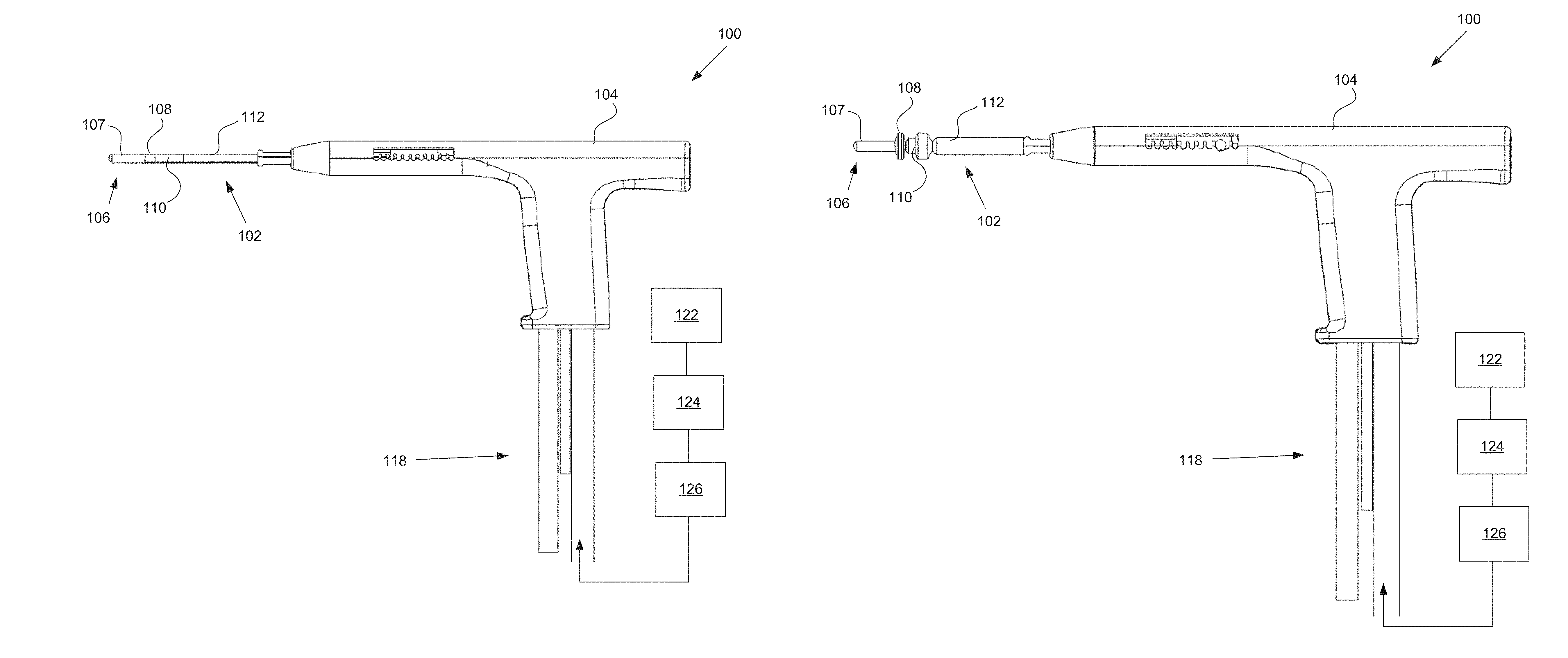
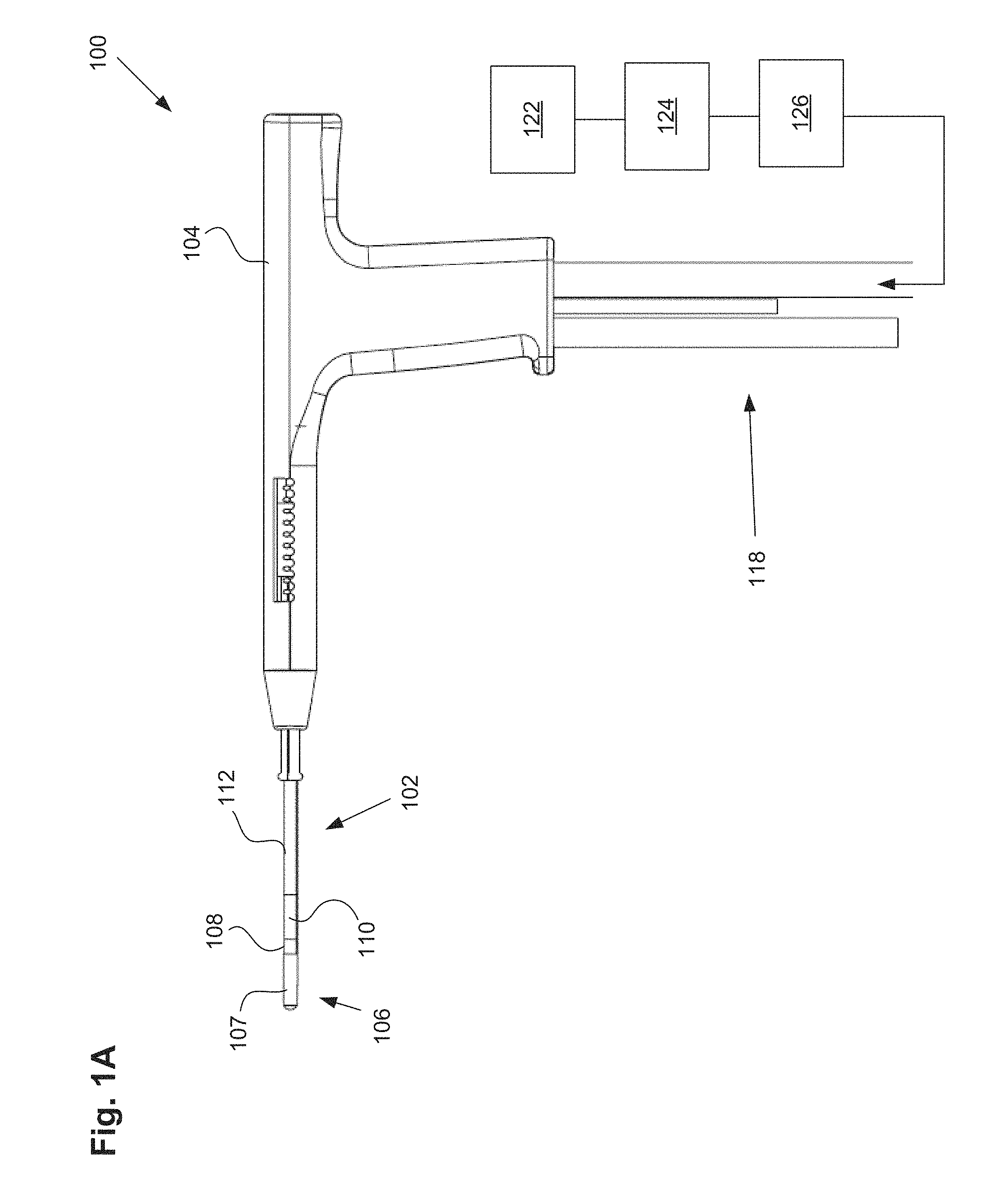
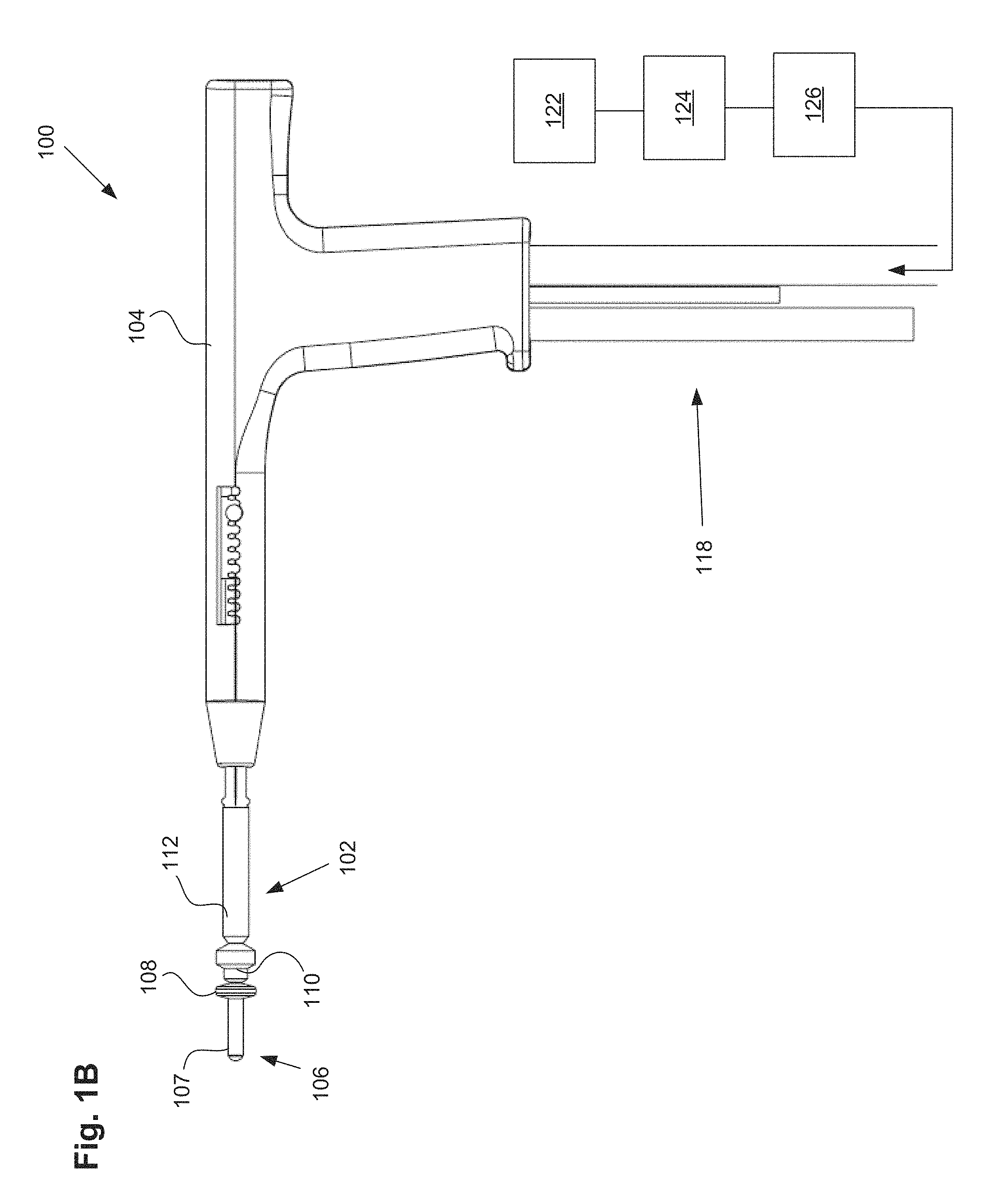
FIGS. 1A-1B illustrate one embodiment of a uterine ablation device.
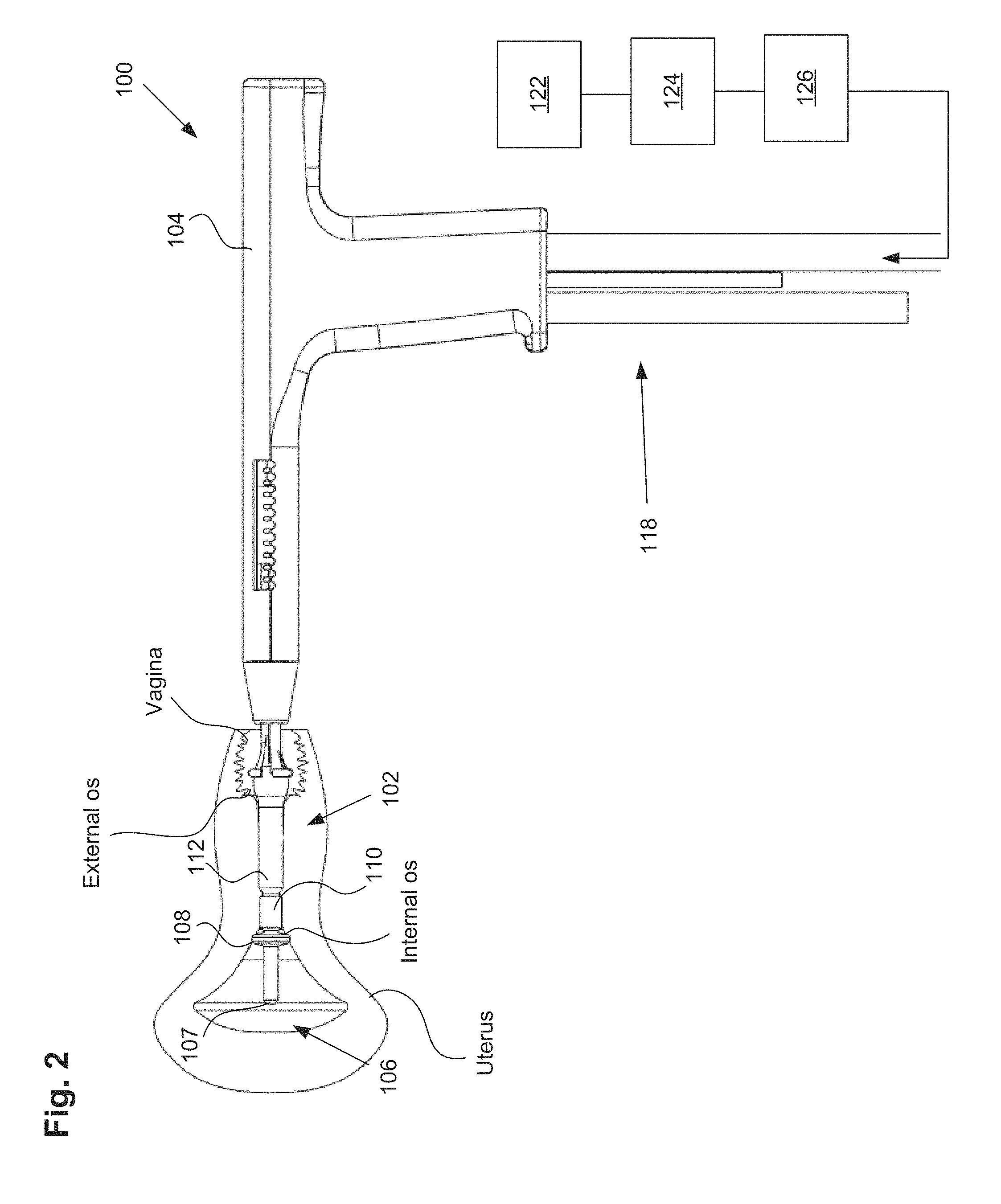
FIG. 2 shows an embodiment of a uterine ablation device inserted into a uterus.
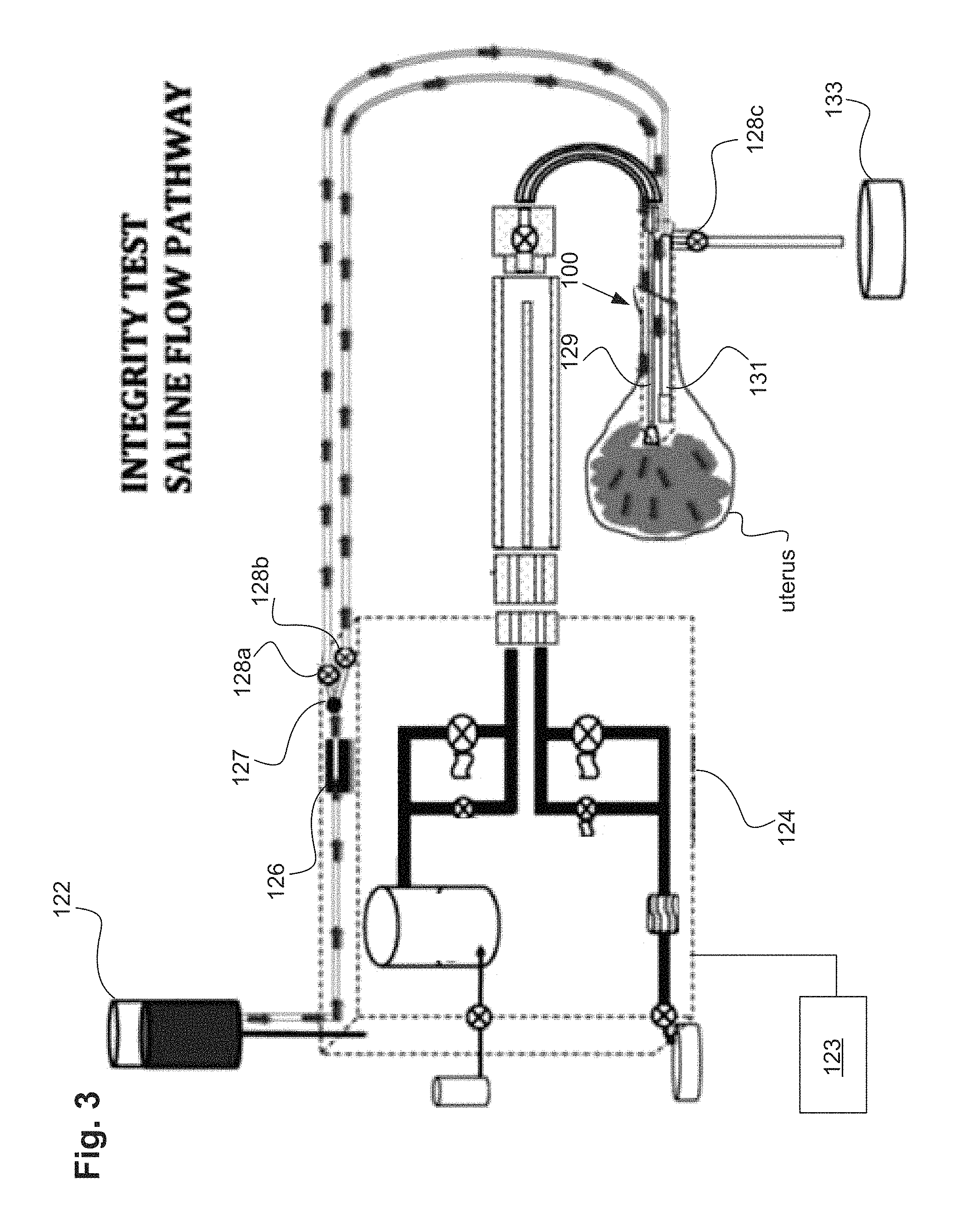
FIG. 3 illustrates an integrity test of the uterine ablation device.
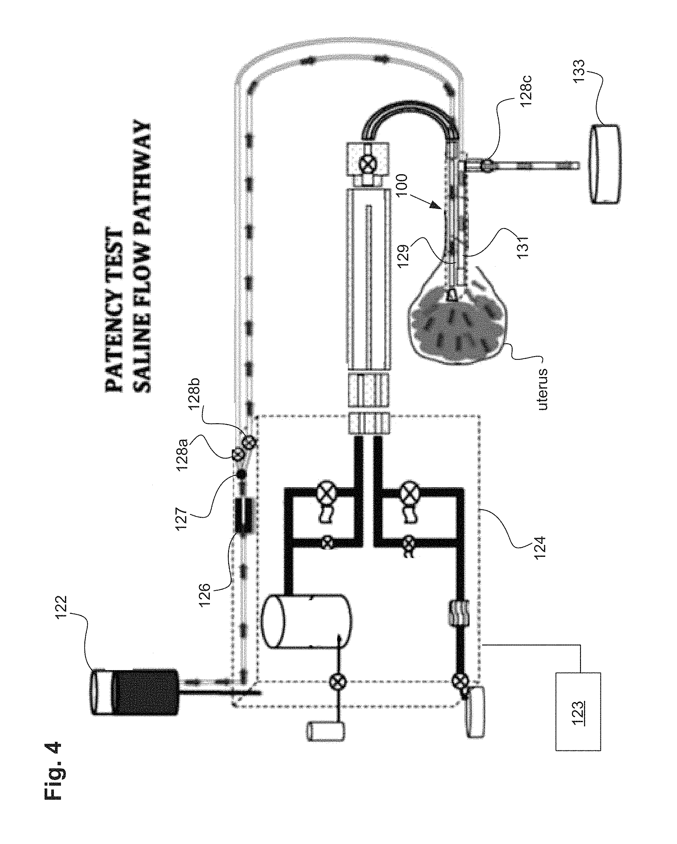
FIG. 4 illustrates a patency test of the uterine ablation device.
FIG. 5 charts the relationship between outflow valve pressure, uterine cavity pressure, and flow through a uterine ablation device.
DETAILED DESCRIPTION
FIG. 1A illustrates a uterine ablation device 100 sized and configured to access the endometrium of a uterus and to deliver a heated vapor to the uterus to ablate uterine tissue. The device can be configured to ablate and treat the endometrial lining of the uterus as an alternative to hysterectomy for treating menorrhagia or other uterine diseases. In some embodiments, the device 100 can be configured to gain access to the uterus by being inserted through a cannula or hysteroscope. The device 100 can include shaft 102, handle 104, distal tip 106, vapor ports 107, distal anchor or distal balloon 108, central or sealing balloon 110, proximal or positioning balloon 112, and connection lumens 118, which can couple the uterine ablation device to a control system (not shown) comprising a computer, a vapor generation system, and mechanisms configured to inflate and deflate the balloons as well as control the delivery and removal of integrity gas/fluid and vapor from the device. Additionally, connection lumens 118 can connect device 100 to a gas/fluid source 122, pressure regulator 124, and flow meter(s) 126. Vapor ports 107 near the distal tip 106 of the device can be fluidly coupled to the connection lumens 118 via inflow and outflow lumens (not shown). The vapor ports, inflow and outflow lumens, connection lumens, gas/fluid source, pressure regulator, and flow meters can be configured for testing the integrity of the patient's uterus, proper placement of the device, and verifying the presence of flow between the inflow and outflow lumens of the device.
The flow meter can be any flow meter as known in the art, including a thermal mass flow meter, an ultrasonic flow meter, a paddlewheel, or a variable area flow meter. In one embodiment, an ultrasonic flow meter that utilizes transit time and Doppler flow readings is advantageous since it is a non-contact system that does not need to physically interact with the fluid or gas media being employed in the integrity test. An ultrasonic flow meter can be easily adaptable to the exterior dimensions of an inflow lumen. In addition, a drip chamber within the inflow lumen can be used to manually visualize or record drips or flow from the fluid source as the integrity test indicates a sealed uterine cavity. In some uterine procedures, it may be advantageous to use other types of fluid besides saline including Lactated Ringers, non-isotonic solutions for certain electrosurgical procedures, gels, foams, fluids of varying viscosity for some ultrasonographic procedures, or other fluids used in uterine procedures.
In one embodiment, a one way valve can be placed in the inflow lumen on either side of the flow meter relative to the gas/fluid source. The one way valve can allow for the flow of gas/fluid (e.g., saline) from the gas/fluid source to the device and uterine cavity. The one way valve should not interfere with the operation of the flow meter and its readings. In operation, the uterine cavity is a muscle that can undergo significant contractions during the integrity and patency tests. These contractions can push the fluid retrograde back through the saline lumen and past the flow meter. In doing so, flow meter measurements can become difficult to interpret or may produce sinusoidal waves in the output readings. The placement of the one way valve in the inflow lumen can eliminate retrograde fluid flow and stabilize readings for the flow meter during episodes of uterine contractions.
Handle 104 can be an ergonomic handle and can include features and controls for using the device (e.g., buttons, levers, indicia for providing feedback for depths of insertion, valves, etc.), including features for controlling inflation of balloons 108, 110, and 112, and for controlling the delivery and removal of integrity test gas/fluid and heated vapor from the device. The handle can also include features and controls for testing the integrity of the patient's uterus, proper placement of the device and verifying the presence of flow between the inflow and outflow lumens of the device.
The balloons described herein can be any type of flexible balloon, such as rubber, latex, urethane, silicone, PET, LDPE, parylene, nylon, PE, combinations of these polymers, or can be manufactured from any other suitable material as known in the art. It should be noted that in some embodiments, the distal anchor comprises a balloon, but in other embodiments, the distal anchor comprises an expandable anchor or expansion mechanism, such as expandable frames, filters, nets, or cages, or non-expandable components that increase the diameter of the shaft of the uterine ablation device. For purposes of this disclosure, however, the distal anchor may be referred to as a distal anchor or as a distal balloon.
Shaft 102 can be configured to deliver a heated vapor from a remote boiler (not shown) through the device and out of vapor ports 107 in distal tip 106. The shaft can also be configured to return vapor that has exited the device, including bodily fluids, uterine materials, and condensate back through the vapor ports and into the shaft. In FIG. 1A, vapor ports 107 are illustrated as including both the vapor delivery and vapor return ports. However, in other embodiments, the vapor delivery ports can be separate and distinct from the vapor return ports. For example, vapor delivery ports are intended to provide an even distribution of heated vapor through a cavity, and may comprise small lumens or holes on the end of the shaft. The vapor return ports, in contrast, are intended to return used vapor and condensate, and may comprise larger slots to prevent blood, tissue, etc. from blocking or clogging the return lumen. The device comprises inflow and outflow gas and/or fluid delivery channels to conduct uterine integrity and patency tests. In some embodiments, the lumens to deliver and return vapor are the same as the channels to deliver and return gas and/or fluid for the uterine integrity and patency tests.
Referring still to FIG. 1A, uterine ablation device 100 is shown in a collapsed delivery configuration, with distal balloon 108, sealing balloon 110, and positioning balloon 112 deflated to reduce the cross sectional diameter of the device and can be 6 mm in diameter during insertion or smaller. When the device is in the delivery configuration, the reduced profile allows for easier access to through the vagina, cervical canal, and cervix to gain access to the uterus, and provides reduced patient discomfort during insertion. In some embodiments, the outer dimensions of the uterine ablation device are such that introduction of the device into the uterine cavity can be achieved without the need for mechanical or pharmacological dilation of the os prior to device introduction.
FIG. 1B illustrates the uterine ablation device 100 of FIG. 1A with all three balloons inflated, including distal balloon 108, central sealing balloon 110, and positioning balloon 112. The central balloon can be inflated with a fluid, such as saline, or alternatively, can be inflated with air. Although three balloons are depicted in FIG. 1B, in other variations one, two, four, or more balloons may be provided, and other balloon shapes may be used. The positioning balloon can be inflated with a room temperature medium, a cooled medium, or alternatively, a heated medium. In some embodiments, the central sealing balloon comprises a length along shaft 102 of approximately 15 mm to 25 mm. The central balloon can be disposed on the shaft between the distal balloon or anchor and the proximal balloon. In some embodiments, the central balloon is adjacent to both the distal balloon and the proximal balloon. In other embodiments, there is a small gap or space between one or more of the balloons. The length and position of the central balloon on the shaft ensures that when inflated, the central balloon seals the cervix off from the uterus near the internal os, but the balloon does not extend into the uterus or into the vagina of the patient. The central and proximal balloons can comprise any diameter, but preferably should have a diameter large enough to be able to engage the walls of the cervix and/or the vagina in the average female patient. For instance, the central balloon may have an inflated outer diameter of 10 mm and accommodate 9.5 psi of pressure in actual use. The proximal balloon can have a larger diameter, such as 17 mm and a lower inflation pressure of 7 psi.
Placement of the ablation device of FIGS. 1A-1B will now be described. The distal tip of the ablation device can be inserted past an external os into the cervical canal of the patient, and past an internal os of the patient to gain access to the uterus. In one embodiment, the distal balloon can be positioned within the uterus distal to the internal os, the sealing balloon can be positioned at or proximal to the internal os and extending into the cervical canal, and the positioning balloon can be positioned within the cervical canal and extending proximally into or towards the vagina.
Once the distal tip of the ablation device is disposed within the uterus, just distal to the internal os, the distal balloon can be inflated to the desired pressure. In some embodiments, the balloon can be inflated to a pressure of up to approximately 20 to 30 psi so as to prevent accidental withdrawal of the ablation device from the uterus. It should be noted that at this point, the distal balloon is positioned slightly past the internal os of the cervix. Inflation of the distal balloon can later serve as an anchor to prevent the device from sliding proximally out of the uterus.
After inflating the distal balloon, the proximal balloon can be inflated to cause the device to assume a positioned configuration, with the distal balloon fully seated against the internal os and the positioning or proximal balloon expanded within the cervix and extending past the external os into the vagina. As the proximal balloon is inflated, the balloon can expand outwardly from the cervix into the relatively unconstrained space of the vagina, which creates a compression force that pulls the device and the distal balloon proximally to engage against the interior portion of the internal os (also known as the cervical ostium or cervical os). FIG. 2 illustrates ablation device 100 inserted into the uterus of a patient with balloons 108, 110, and 112 inflated as described above.
After positioning the ablation device but prior to delivery of vapor, it can be advantageous to assess the integrity of the uterus to test that the vapor delivery tip of the device is positioned within a sealed uterus and to test that there is flow between the inflow and outflow lumens, by performing an integrity test and a patency test. The amount of fluid and rate in which it flows into the uterine cavity can provide the physician an indication of the size of the uterine cavity and whether the device is in a false passage. An integrity test can asses that the uterus is sealed, and determine leaks originating from 1) perforations to the uterine wall, or 2) leaks from inadequate sealing at the cervix or 3) leaks from the fallopian tubes.
A second test that made an assessment for patency, referred to as the device lumens patency test or patency test, could provide an indication to the physician whether the device was clogged with debris or placed within a false passage. This additional information to the physician, in conjunction with the integrity test, can provide greater assurance to the physician of device location during "blind" endometrial ablation procedures.
In clinical use, a uterine integrity and patency test could be useful for additional uterine procedures besides uterine ablation procedures such as the implantation of a device, implant, or a diagnostic or therapeutic agent. In these cases, a separate unit or module that can conduct a uterine integrity and patency test, sequentially, separately, or individually, with a separate uterine cavity introducer can be employed without a uterine ablation device or system.
In one embodiment, a uterine integrity test can contain the following elements and steps. Referring to FIGS. 1A-1B and FIG. 2, gas/fluid source 122 can be connected to pressure regulator 124 comprising either one regulator or an additional back pressure regulator. The gas/fluid source can contain a gas, such as CO.sub.2, or inert gases, or a fluid, such as saline, Ringer's Lactate, non-isotonic solutions, glycerine, and mineral oil for example. The regulator 124 can be configured to keep the pressure of the external gas source below a safety threshold value. In one embodiment, the safety threshold value can be approximately 70 mm Hg. The actual pressure amount or graduation may not be monitored and may not need to be. The fluid or gas from gas/fluid source 122 can be driven at a constant pressure bounded by the safety threshold value (e.g., can be bounded by the maximum pressure the uterus will see during treatment, such as 70 mm Hg). In addition, it can be useful to operate a uterine integrity test at a pressure equal to higher than the pressure required for conducting the endometrial ablation or other uterine procedure.
In one embodiment, gas/fluid pressure can be achieved by elevating the gas/fluid source 122 a height distance above the uterine cavity to create pressure. This height elevation can be verified by a measuring stick, tape or laser. An example of a clinically used height for a saline bag would be at least 30 inches above the patient's uterus. At this height, the pressure would be between 50 and 70 mmHg. This pressure is low enough to be below the reported opening pressure of the fallopian tubes. In addition, a pressure sensor within the uterine cavity can verify that the appropriate amount of pressure is being applied for the integrity test and patency tests. A self-adjusting feedback mechanism can be employed to raise or lower the pressure of the saline source in response to pressure measurements taken from within the uterine cavity. As an example, this feedback mechanism can raise or lower the height of the saline source in response to the pressure measurements taken from within the uterine cavity.
In some embodiments, the system can measure a flow rate of gas/fluid exiting the distal lumen of the uterine device or uterine ablation device during the uterine integrity test. This flow rate can also be used to determine the proper pressure or height of the gas/fluid source. For instance, flow rate readings can be taken while the gas/fluid source is at a certain height and the uterine device maintained within a known condition or in free space. As the height of the gas/fluid source is raised or lowered, the flow rate of the gas/fluid will respond accordingly until the gas/fluid source is placed at a height at the desired flow rate, or is pressurized to the desired amount. Likewise, the gas/fluid source can be raised or lowered by a self-adjusting feedback mechanism in response to the measured flow rate.
In some embodiments, the uterine ablation device can further include a flow meter 126 having a read out mechanism (not shown) to the end user. In one embodiment, the flow meter can comprise an ultrasound sensor, or an optical sensor configured to sense the drip rate of the gas/fluid. In some embodiments, the flow meter can be disposed near distal tip 106 of the device. In other embodiments, the flow meter can be disposed within an outflow lumen of the device. In yet another embodiment, the flow meter can be disposed external to the device but along the flow path between gas/fluid source 122 and the ablation device. The flow meter can be configured to measure and report a flow rate of fluid/gas or vapor as it moves through or exits the uterine ablation device. The read out mechanism can be numerical, graphical, or icon based. Other variations include various audio and visual signals, indicia, qualitative indicia, alarms, and color identifiers. A filter may or may not be attached to the flow meter.
Referring to FIGS. 2 and 3, to perform a uterine integrity test, gas, such as CO.sub.2, or a fluid, such as saline, can be delivered from the gas/fluid source 122, through a pressure regulator, and through a flow meter 126 into the uterine ablation device 100. As shown in FIG. 3, the gas/fluid can be delivered into the uterus via both inflow lumen 129 and outflow lumen 131. In one specific embodiment, a saline such as 0.9% NaCl can be delivered into the uterus during a uterine integrity test, to determine whether there are leaks in the uterus or cervical canal through which vapor could escape during an ablation procedure. The uterine ablation device 100 can be coupled to an energy generator 124 and controller 123 for uterine ablation therapy. The vapor generator can be, for example, a vapor generator (as shown), but can also be any other type of energy generator, such as an RF energy generator, a cryotherapy generator, etc. Any type of energy modality can be used to ablate or treat the uterus after performing the integrity and patency tests described herein.
In one embodiment, a one way valve 127 as seen in FIG. 3 can be located between the flow meter 126 and the uterine ablation device 100. In other variations the one way valve 127 can be located in the handle of the uterine ablation device 100 as well as other components such as the flow meter 126 and valves 128a, 128b, and 128c. The one way valve can reduce or eliminate retrograde flow of saline during uterine contractions. The one way valve is characterized as providing low resistance to flow in one direction (towards the uterine cavity) and high resistance to flow in the retrograde direction (towards the gas/fluid source). Advantageously the one way valve can stabilize flow values because retrograde flow values are eliminated. By reducing the sinusoidal wave patterns that can be caused by uterine contractions or relaxations, movements by the patient, or inadvertent manipulations of the inflow line or the patient herself by the physician or medical staff, the procedure time is reduced. This filtering out of negative flow values isolates positive components of flow, reduces noise in flow rate values, thereby accelerating the interpretation of flow rate data and reducing procedural time.
A controller of the uterine ablation device, either integrated into the device or into the vapor generator coupled to the device, can be configured to open and close valves 128a, 128b, and 128c to allow gas or fluid to flow from source 122 into the inflow and outflow lumens 129 and 131 of the ablation device 100. Valves 128a, 128b, and 128c can be any type of valve known in the art, such as solenoid valves, inflatable balloons, air cylinders, or electric/hydraulic actuators or cams and gears. During a uterine integrity test, the controller can be configured to open valves 128a and 128b and close valve 128c, to prevent passage of gas/fluid into the waste container 133. This allows gas or fluid to flow from source 122, through flow meter 126, through one way valve 127 and valves 127a and 128b, and into inflow lumen 129 and outflow lumen 131. As the gas or fluid enters the uterus, the flow meter can measure an integrity flow rate of the gas or fluid.
In one embodiment, the controller of the uterine ablation device or the vapor generator can run an integrity test algorithm to determine if the uterus is sealed. The algorithm can analyze integrity flow rate data from the flow meter during the integrity test as gas/fluid is delivered into the uterus. Specifically, the algorithm can analyze a maximum flow rate and a minimum flow rate during an integrity test time window. The integrity test time window can be, for example, a rolling time window of a pre-selected duration. In one specific embodiment, the algorithm analyzes a maximum flow rate and a minimum flow rate continuously during a rolling 15-second integrity test time window. For each rolling integrity test time window, the minimum and maximum flow rates can be calculated. The difference between the minimum and maximum flow rates in each integrity test time window can be calculated to yield a delta flow value (maximum flow rate minus minimum flow rate), which can be used as an indicator of the stability of flow. For example, the larger the delta flow value, the less stable the flow of gas/fluid, and the smaller the delta flow value, the more stable the flow of gas/fluid. If the maximum flow rate and the delta flow value of gas or fluid stabilizes below an integrity threshold value, the controller can determine that the uterus is sealed. Importantly, the test is comprised of two algorithms that compare flow to an integrity threshold value concurrently with a second algorithm that compares the delta flow value to the integrity threshold value, and uses both of these comparisons to determine the ultimate outcome of the integrity test. The application of both of these comparisons provides greater sensitivity in the test results.
In some embodiments, this integrity flow rate delta threshold value can be approximately 5 ml/min. Therefore, in some embodiments, a uterus is considered to "pass" the uterine integrity test if both the maximum flow rate and the integrity flow rate delta threshold value are below 5 ml/min over a rolling integrity test time window. Alternatively, the test can include different thresholds for maximum flow rate and the delta flow value.
In some embodiments, the uterine integrity test can run for a pre-set time period. For example, the test can run for 60 seconds, and subsequent rolling 15-second windows can be analyzed to determine if the uterus is sealed during the 60 second time period. In another embodiment, the delta flow value can be defined as a standard deviation of the average flow that is compared to a threshold value. This delta flow value can then be compared to the threshold value to determine if the uterus is sealed.
In some embodiments, the return channel comprises a valve 128c, such as a solenoid valve, air cylinder, electric/hydraulic actuators, cams and gears or pump/inflatable balloon, which can be activated upon the start of the integrity test to close off the egress of the gas/fluid through the return channel of the uterine ablation device. When the return flow of gas/fluid through the return channel is stopped with the valve, a change of flow can be detected by the flow meter 126 on the input line. In addition to determining if there is a leak or if the device is positioned properly, the specifics of the changes in flow (e.g., how the flow reacts to closing of the return line with the valve) can provide the following the indications in some cases: a) the size of the uterine cavity; and b) the presence of a leak or lack of integrity in the system. For instance in clinical use with uteri of varying sizes, an integration under the graphical curve of flow rate versus time provides a volume assessment of the size of uterine cavity. The amount of volume can provide the physician information not only on the size of the uterus, but whether the device is improperly embedded in a false passage (smaller volume amount) or in the peritoneal cavity (larger volume amount).
Immediately after performing the integrity test above, the amount of flow in the inflow and outflow channels can be measured in a patency test and used to determine the presence of an obstruction that may affect the flow of vapor during the ablation procedure. Based on this determination or patency test, the device may be repositioned or replaced prior to delivery of vapor. For example, in one embodiment, referring to FIG. 4, a method of performing a patency test can comprise delivering gas or fluid from inflow lumen 129 of the uterine device into the uterus, also referred to as the fluid infusion tip, removing gas or fluid from the uterus with outflow lumen 131 of the uterine device, also referred to as the fluid outflow tip, and determining that the uterine device is not clogged or embedded in tissue if a flow rate of gas or fluid is observed in the flow meter of the inflow lumen of the uterine device. In FIGS. 3-4, valves 128a and 128b control the flow of gas/fluid to the uterine ablation device 100 and valve 128c control the flow of gas/fluid from the outflow lumen 131 into the outflow canister or waste container 133. Control of the valves 128a and 128b and 128c can be performed by a separate controller and software unit shown as 123.
If it has been determined that the uterus is sealed based on the integrity test performed and described in FIG. 3, the controller can also be configured to perform a patency test. In one embodiment, referring to FIG. 4, the controller can be configured to open valves 128b and 128c, but close valve 128a. This allows gas or fluid to flow from source 122, through flow meter 126, through one way valve 127 and valve 128b, and into inflow lumen 129. Gas or fluid can be removed through outflow lumen 131, through valve 128c, and into a waste container 133. As the gas or fluid enters and is removed from the uterus, the flow meter can measure a patency flow rate of the gas or fluid. If the patency flow rate is maintained above a patency flow rate threshold value, the controller can determine that the device is not clogged or embedded into tissue. In some embodiments, observing or measuring a flow of fluid or gas in outflow lumen 131 can be used to determine that the device is not clogged or embedded in tissue. A flow rate above a patency test threshold during a rolling patency test time window can indicate that the lumens are not clogged or that the distal end of the uterine ablation device is not embedded into tissue.
In one specific embodiment, the patency test threshold can be greater than 5 ml/min, and the rolling patency test time window can be a 5 second time period. Thus, the flow meter can measure the patency flow rate in rolling patency time windows (e.g., rolling 5 second periods) and the controller can analyze the measured rate. If the patency flow rate is maintained above the patency test threshold (e.g., 5 ml/min) during a rolling patency time window, then the patency test is considered passed and the test can be stopped. Passing the patency test indicates that the uterine ablation device is not obstructed or placed in false passage. If the patency test threshold is not satisfied, the physician should repeat the insertion steps and/or repeat the integrity test and patency test prior to initiating uterine ablation. When the patency flow rate is below the threshold of 5 ml/min during the rolling patency test time window, the uterine ablation device may need to be repositioned.
During the transition from the end of integrity test to the start of the patency test, the uterine cavity can be substantially filled with the gas/fluid provided during the integrity test. As described above, the closed outflow valve during the integrity test prevents gas or fluid from exiting the uterine cavity into the waste container 133. In one embodiment, it is desirable for valve 128c to be opened only partially in the range of 20-50% open for a flow rate greater than 5 ml/min and less than 40 ml/min so the uterine cavity distension achieved during the integrity test is temporarily maintained when the patency test checks for open flow through the uterine ablation device. Certain types of valves are better suited for partial opening. For example, balloon valves can be pulsed at various duty cycles to partially open the valve. The higher the duty cycle, the more quickly the valve can be opened. Partial opening of the valve prevents the uterine cavity from collapsing too quickly around the tip of the uterine ablation device which, in some instances, may cause a false positive failure of the patency test. In one embodiment, partial opening of the valve can be achieved by pulsing the opening of the valve at a specified duty cycle until flow through the vapor probe begins, or alternatively until the uterine pressure begins to drop. In another embodiment, the valve 128c can be opened rapidly just until flow through the valve begins. This rapid drop opening of the valve can be achieved by pulsing the valve initially with a high duty cycle, then shortening the pulsing (or lowering the duty cycle) as the valve approaches the range where flow through the valve begins. Once the patency flow rate increases above a threshold (or by a specific rate of increase), the valve can be maintained.
In one specific embodiment, the valve 128c can be a balloon filled to as much as 20 psig to occlude the tubing leading to waste container 133. The balloon valve can be pulsed open for up to 40 msec every 200 msec until the balloon pressure falls to as low as 5 psig. The valve opening time can then be reduced even further until the balloon pressure falls to between 3-4 psig. The valve can continue to be pulsed until flow increases to a level of 0.20 ml/min or until flow rises above the threshold value (e.g., above 5 ml/min).
FIG. 5 shows one specific embodiment where the outflow valve (e.g., valve 128c from FIG. 3) comprises an inflatable balloon. Inflating the balloon causes obstruction of the outflow lumen of the uterine ablation device, and deflating the balloon allows flow out of the device and into the waste container. FIG. 5 shows the outflow valve pressure 136 (psi), the flow 138 (ml/min) through the uterine ablation device, and the uterine cavity pressure 140 (mmHg) during a typical patency test. At the completion of a typical integrity test, the cavity pressure should be above 52 mmHg, the outflow valve pressure about 20 psi, and the flow through the uterine ablation device close to zero. In the first few seconds of the patency test, the outflow valve pressure decreases rapidly, then the rate of deflation decreases to zero as flow through the device begins, shown by arrow 142. The cavity pressure drops gradually as flow increases. The patency algorithm can run concurrently with deflation of the outflow valve. In some embodiments, the deflation period of the outflow valve is typically from 3 to 40 msec.
As for additional details pertinent to the present invention, materials and manufacturing techniques may be employed as within the level of those with skill in the relevant art. The same may hold true with respect to method-based aspects of the invention in terms of additional acts commonly or logically employed. Also, it is contemplated that any optional feature of the inventive variations described may be set forth and claimed independently, or in combination with any one or more of the features described herein. Likewise, reference to a singular item includes the possibility that there are plural of the same items present. More specifically, as used herein and in the appended claims, the singular forms "a," "and," "said," and "the" include plural referents unless the context clearly dictates otherwise. It is further noted that the claims may be drafted to exclude any optional element. As such, this statement is intended to serve as antecedent basis for use of such exclusive terminology as "solely," "only" and the like in connection with the recitation of claim elements, or use of a "negative" limitation. Unless defined otherwise herein, all technical and scientific terms used herein have the same meaning as commonly understood by one of ordinary skill in the art to which this invention belongs. The breadth of the present invention is not to be limited by the subject specification, but rather only by the plain meaning of the claim terms employed.
* * * * *
D00000
D00001
D00002
D00003
D00004
D00005
D00006
XML
uspto.report is an independent third-party trademark research tool that is not affiliated, endorsed, or sponsored by the United States Patent and Trademark Office (USPTO) or any other governmental organization. The information provided by uspto.report is based on publicly available data at the time of writing and is intended for informational purposes only.
While we strive to provide accurate and up-to-date information, we do not guarantee the accuracy, completeness, reliability, or suitability of the information displayed on this site. The use of this site is at your own risk. Any reliance you place on such information is therefore strictly at your own risk.
All official trademark data, including owner information, should be verified by visiting the official USPTO website at www.uspto.gov. This site is not intended to replace professional legal advice and should not be used as a substitute for consulting with a legal professional who is knowledgeable about trademark law.