Lighting system having two or more LED packages having a specified separation distance
Miskin , et al. April 20, 2
U.S. patent number 10,986,714 [Application Number 15/334,001] was granted by the patent office on 2021-04-20 for lighting system having two or more led packages having a specified separation distance. This patent grant is currently assigned to Lynk Labs, Inc.. The grantee listed for this patent is Lynk Labs, Inc.. Invention is credited to Robert L. Kottritsch, Michael Miskin.


| United States Patent | 10,986,714 |
| Miskin , et al. | April 20, 2021 |
Lighting system having two or more LED packages having a specified separation distance
Abstract
An LED lighting system is disclosed. In an example, an LED lighting system includes at least one lighting device, at least one driver, an LED circuit, and a switch. The driver has at least one bridge rectifier. The driver has a first voltage input from a mains power source and provides a second lower voltage output to the at least one lighting device. The LED circuit has two or more LEDs integrated in the at least one lighting device. The switch is integrated in the at least one lighting device and controllable by an end user. Additionally, the lighting device is configured to provide multiple brightness levels and/or color levels in response to control of the switch by the end user.
| Inventors: | Miskin; Michael (Sleepy Hollow, IL), Kottritsch; Robert L. (Shefford, GB) | ||||||||||
|---|---|---|---|---|---|---|---|---|---|---|---|
| Applicant: |
|
||||||||||
| Assignee: | Lynk Labs, Inc. (Elgin,
IL) |
||||||||||
| Family ID: | 1000005503113 | ||||||||||
| Appl. No.: | 15/334,001 | ||||||||||
| Filed: | October 25, 2016 |
Prior Publication Data
| Document Identifier | Publication Date | |
|---|---|---|
| US 20170105256 A1 | Apr 13, 2017 | |
Related U.S. Patent Documents
| Application Number | Filing Date | Patent Number | Issue Date | ||
|---|---|---|---|---|---|
| 14172644 | Feb 4, 2014 | 9750098 | |||
| 13322796 | Feb 11, 2014 | 8648539 | |||
| PCT/US2010/001597 | May 28, 2010 | ||||
| 12287267 | May 15, 2012 | 8179055 | |||
| 61217215 | May 28, 2009 | ||||
| 60997771 | Oct 6, 2007 | ||||
| Current U.S. Class: | 1/1 |
| Current CPC Class: | H05B 45/40 (20200101); H05B 45/37 (20200101); Y10T 29/49002 (20150115) |
| Current International Class: | H05B 45/37 (20200101); H05B 45/40 (20200101) |
| Field of Search: | ;257/79,88 ;315/185R,291 ;362/249.02 |
References Cited [Referenced By]
U.S. Patent Documents
| 3869641 | March 1975 | Goldberg |
| 4218627 | August 1980 | Kiesel |
| 4271408 | June 1981 | Teshima |
| 4298869 | November 1981 | Okuno |
| 5469020 | November 1995 | Herrick |
| 5636303 | June 1997 | Che et al. |
| 5699218 | December 1997 | Kadah |
| 5790013 | August 1998 | Hauck |
| 5803579 | September 1998 | Turnbull et al. |
| 5936599 | August 1999 | Reymond |
| 6016038 | January 2000 | Mueller et al. |
| 6028694 | February 2000 | Schmidt |
| 6072280 | June 2000 | Allen |
| 6072475 | June 2000 | van Ketwich |
| 6107744 | August 2000 | Bavaro et al. |
| 6127783 | October 2000 | Pashley et al. |
| 6234648 | May 2001 | Borner |
| 6292901 | September 2001 | Lys et al. |
| 6357889 | March 2002 | Duggal et al. |
| 6412971 | July 2002 | Wojnarowski et al. |
| 6528954 | March 2003 | Lys et al. |
| 6541919 | April 2003 | Roach et al. |
| 6548967 | April 2003 | Dowling et al. |
| 6559802 | May 2003 | Goto et al. |
| 6580228 | June 2003 | Chen et al. |
| 6614103 | September 2003 | Durocher et al. |
| 6636003 | October 2003 | Rahm et al. |
| 6641294 | November 2003 | Lefebvre |
| 6667497 | December 2003 | Huang et al. |
| 6714348 | March 2004 | Dunn |
| 6762562 | July 2004 | Leong |
| 6781570 | August 2004 | Arrigo et al. |
| 6828596 | December 2004 | Steigerwald et al. |
| 6861658 | March 2005 | Fiset |
| 6909234 | June 2005 | Chen |
| 7014336 | March 2006 | Ducharme et al. |
| 7019062 | March 2006 | van Beek et al. |
| 7038399 | May 2006 | Lys et al. |
| 7053560 | May 2006 | Ng |
| 7064498 | June 2006 | Dowling et al. |
| 7081722 | July 2006 | Huynh et al. |
| 7288902 | October 2007 | Melanson |
| 7339198 | March 2008 | Shen |
| 7344279 | March 2008 | Mueller et al. |
| 7400439 | July 2008 | Holman |
| 7462997 | December 2008 | Mueller et al. |
| 7489086 | February 2009 | Miskin et al. |
| 7535028 | May 2009 | Fan et al. |
| 7583901 | September 2009 | Nakagawa et al. |
| 7748877 | July 2010 | Colby |
| 7859196 | December 2010 | Lee et al. |
| 8076680 | December 2011 | Lee |
| 8129917 | March 2012 | Kim et al. |
| 8148905 | April 2012 | Miskin et al. |
| 8179055 | May 2012 | Miskin et al. |
| 8198819 | June 2012 | Lenk |
| 8272757 | September 2012 | Fan et al. |
| 8314571 | November 2012 | Jonsson |
| 8378374 | February 2013 | Loh |
| 8384299 | February 2013 | Burdalski |
| 8531118 | September 2013 | Miskin et al. |
| 8648539 | February 2014 | Miskin et al. |
| 8841855 | September 2014 | Miskin |
| 9184497 | November 2015 | Chen et al. |
| 9198237 | November 2015 | Miskin et al. |
| 2001/0054005 | December 2001 | Hook et al. |
| 2002/0048169 | April 2002 | Dowling et al. |
| 2002/0060526 | May 2002 | Timmermans et al. |
| 2002/0181231 | December 2002 | Luk |
| 2003/0043611 | March 2003 | Bockle et al. |
| 2003/0100837 | July 2003 | Piepgras et al. |
| 2003/0122502 | July 2003 | Clauberg et al. |
| 2003/0137258 | July 2003 | Piepgras et al. |
| 2003/0156422 | August 2003 | Tatewaki et al. |
| 2003/0169014 | September 2003 | Kadah |
| 2003/0175004 | September 2003 | Garito et al. |
| 2003/0219035 | November 2003 | Schmidt |
| 2004/0075399 | April 2004 | Hall |
| 2004/0080941 | April 2004 | Jiang et al. |
| 2004/0183380 | September 2004 | Otake |
| 2004/0189218 | September 2004 | Leong et al. |
| 2004/0201988 | October 2004 | Allen |
| 2004/0206970 | October 2004 | Martin |
| 2004/0218387 | November 2004 | Gerlach |
| 2004/0264193 | December 2004 | Okumura |
| 2005/0040773 | February 2005 | Lebens et al. |
| 2005/0110426 | May 2005 | Shao |
| 2005/0128751 | June 2005 | Roberge et al. |
| 2005/0168156 | August 2005 | Li et al. |
| 2005/0173990 | August 2005 | Anderson et al. |
| 2005/0195600 | September 2005 | Porchia et al. |
| 2006/0038542 | February 2006 | Park et al. |
| 2006/0103913 | May 2006 | Handschy et al. |
| 2006/0138971 | June 2006 | Uang et al. |
| 2006/0158130 | July 2006 | Furukawa |
| 2006/0176692 | August 2006 | Lee et al. |
| 2006/0238136 | October 2006 | Johnson, III et al. |
| 2006/0256826 | November 2006 | Lin et al. |
| 2006/0285332 | December 2006 | Goon et al. |
| 2007/0069663 | March 2007 | Burdalski et al. |
| 2007/0103899 | May 2007 | Takikawa |
| 2007/0115248 | May 2007 | Roberts et al. |
| 2007/0247852 | October 2007 | Wang |
| 2007/0258231 | November 2007 | Koerner et al. |
| 2008/0017871 | January 2008 | Lee |
| 2008/0094005 | April 2008 | Rabiner et al. |
| 2008/0094837 | April 2008 | Dobbins et al. |
| 2008/0116816 | May 2008 | Neuman et al. |
| 2008/0116818 | May 2008 | Shteynberg et al. |
| 2008/0136347 | June 2008 | Lin et al. |
| 2008/0158915 | July 2008 | Williams |
| 2008/0203405 | August 2008 | Rooymans |
| 2008/0203936 | August 2008 | Mariyama et al. |
| 2008/0211421 | September 2008 | Lee et al. |
| 2008/0218098 | September 2008 | Lee et al. |
| 2008/0252197 | October 2008 | Li et al. |
| 2009/0009100 | January 2009 | Rooymans |
| 2009/0221185 | January 2009 | Ng |
| 2009/0079362 | March 2009 | Shteynberg et al. |
| 2009/0134413 | May 2009 | Roth |
| 2009/0167190 | July 2009 | Hickey |
| 2009/0289267 | November 2009 | Burdalski |
| 2009/0295300 | December 2009 | King |
| 2010/0039794 | February 2010 | Ghanem et al. |
| 2010/0045202 | February 2010 | That |
| 2010/0072905 | March 2010 | Kim et al. |
| 2010/0109564 | May 2010 | Shin et al. |
| 2010/0259183 | October 2010 | Leshniak |
| 2010/0277084 | November 2010 | Lee |
| 2010/0308738 | December 2010 | Shteynberg et al. |
| 2011/0001422 | January 2011 | Aanegola |
| 2011/0115407 | May 2011 | Wibben et al. |
| 2011/0148327 | June 2011 | Van de Ven et al. |
| 2011/0169408 | July 2011 | Chen et al. |
| 2011/0260648 | October 2011 | Hamamoto et al. |
| 2012/0043897 | February 2012 | Miskin et al. |
| 2012/0268008 | October 2012 | Miskin et al. |
| 2012/0293083 | November 2012 | Miskin et al. |
| 2013/0051001 | February 2013 | Miskin |
| 2016/0095180 | March 2016 | Miskin |
| 1076476 | Mar 2002 | EP | |||
| 1 215 944 | Jun 2002 | EP | |||
| S6230386 | Feb 1987 | JP | |||
| 08-137429 | May 1996 | JP | |||
| 11-016683 | Jan 1999 | JP | |||
| 11-330561 | Nov 1999 | JP | |||
| 2000156526 | Jun 2000 | JP | |||
| 2002057376 | Feb 2002 | JP | |||
| 2001291406 | Apr 2003 | JP | |||
| 2003298118 | Oct 2003 | JP | |||
| 2004111104 | Apr 2004 | JP | |||
| 2005222750 | Aug 2005 | JP | |||
| 2007059260 | Mar 2007 | JP | |||
| 3162876 | Sep 2010 | JP | |||
| 9922338 | May 1999 | WO | |||
| 0215320 | Feb 2002 | WO | |||
| 03019072 | Mar 2003 | WO | |||
| 03055273 | Jul 2003 | WO | |||
| WO 03/075126 | Sep 2003 | WO | |||
| 2004094896 | Nov 2004 | WO | |||
| WO2009/045548 | Apr 2005 | WO | |||
| WO 2005084080 | Sep 2005 | WO | |||
| WO 2007001116 | Jan 2007 | WO | |||
| WO 2008/062941 | May 2008 | WO | |||
| 2008124701 | Oct 2008 | WO | |||
| WO 2011049613 | Apr 2011 | WO | |||
| WO 2011082168 | Jul 2011 | WO | |||
| WO 2011143510 | Nov 2011 | WO | |||
| 2016164928 | Oct 2016 | WO | |||
Other References
|
Citizen Electronics Co., Ltd.'s datasheet for CL-820-U1N CITILEDs dated Aug. 6, 2007. cited by applicant . Fairchild Semiconductor Corporation's "Surface Mount LED Lamp Super Bright 0805" datasheet dated Aug. 30, 2001. cited by applicant . M. Rico-Secades et al., "Driver for high efficiency LED based on flyback stage with current mode control for emergency lighting system," Industry Applications Conference, Oct. 2004, pp. 1655-1659. cited by applicant . International Search Report for International Application PCT/US2008/011536, 14 pages. cited by applicant . Office Action for Related CA Application No. 2,701,780 dated Nov. 6, 2014, 4 pages. cited by applicant . Decision on Institution of Inter Partes Review under 37 CFR 42.108 for U.S. Pat. No. 8,841,855, 40 pages. cited by applicant . Patent Owners Preliminary Response under 37 CFR 42.107 for Case IPR2016-01133 for Inter Partes Review of U.S. Pat. No. 8,841,855, 51 pages. cited by applicant . Lynk Labs, Inc.'s Initial Response to Invalidity Contentions, Northern District of Illinois Civil Action No. 15-cv-04833, 88 pages. cited by applicant . European Search Report dated Oct. 22, 2012 in related European Application, seven (7) pages. cited by applicant . International Search Report and Written Opinion for International Application No. PCT/US2010/001597 dated Jul. 30, 2010 containing 14 pages. cited by applicant . Examination Report Under Sections 12 & 13 of the Patent Act for Indian Application No. 9150/delnp/2011 dated Apr. 5, 2018, 6 pages. cited by applicant . Examination Report Under Sections 12 & 13 of the Patent Act, Indian Application No. 5795/DELNP/2012, dated Aug. 29, 2018, 6 pages. cited by applicant . Office Action, Canadian Application No. 2,763,598, dated Jul. 3, 2018, 3 pages. cited by applicant . Extended European Search Report dated Jan. 14, 2020, Application No. EP19177733.3, 10 pages. cited by applicant. |
Primary Examiner: Chang; Daniel D
Attorney, Agent or Firm: K&L Gates LLP
Parent Case Text
RELATED APPLICATIONS
This application is continuation-in-part of U.S. patent application Ser. No. 14/172,644 filed Feb. 4, 2014, which is a continuation of U.S. patent application Ser. No. 13/322,796 now U.S. Pat. No. 8,648,539, filed Nov. 28, 2011, which is a national phase application of International Application No. PCT/US2010/001597, filed May 28, 2010, which claims priority to U.S. Provisional Application No. 61/217,215, filed May 28, 2009, and is a continuation-in-part of U.S. patent application Ser. No. 12/287,267 now U.S. Pat. No. 8,179,055, filed Oct. 6, 2008, which claims the priority to U.S. Provisional Application No. 60/997,771, filed Oct. 6, 2007; the contents of each of these applications are expressly incorporated herein by reference.
Claims
What is claimed is:
1. An LED lighting system comprising: at least one lighting device; at least one LED circuit integrated into the at least one lighting device, wherein the at least one LED circuit includes at least two LEDs that are mounted on a single substrate, and wherein at least one of the at least two LEDs includes a different phosphor coating than that of at least one other LED of the at least two LEDs; at least one driver having a first voltage input from an AC mains power source and providing a second lower voltage output to the at least one LED circuit, wherein the at least one lighting device is capable of being electrically coupled to an output of the at least one driver; and a switch configured to enable a change in a color of light emitted from the at least one lighting device to be set by an end user by causing one of at least a change in current or turning `on` or `off` the at least one LED with the different phosphor coating of the at least two LEDs in the at least one LED circuit, and wherein the switch has at least two positions selectable by the end user, and wherein the at least one LED circuit and the switch are integrated within the at least one lighting device such that the switch is positioned to enable actuation by the end user.
2. The LED lighting system of claim 1, wherein the at least two LEDs are electrically connected together in series or in parallel and are separated from each other by a distance of 3 mm or less.
3. The LED lighting system of claim 1, further comprising: a bridge rectifier.
4. The LED lighting system of claim 1, wherein the at least two LEDs in the at least one LED circuit are driven with an AC voltage of at least 6V.
5. The LED lighting system of claim 1, wherein the LED lighting system is integrated into an LED lamp.
6. The LED lighting system of claim 1, wherein the LED lighting system has at least one of a voltage level input to the at least one LED, a current level input to the at least one LED, or a brightness level input to the at least one LED that is selectable by the end user via the switch.
7. A lighting system comprising: at least one lighting device; at least one LED circuit integrated into the at least one lighting device, wherein the least one LED circuit includes at least two LEDs mounted on a substrate, wherein at least one of the at least two LEDs includes a different phosphor coating than that of at least one other LED of the at least two LEDs, and wherein the at least two LEDs are electrically connected together in series or in parallel and are separated from each other by a distance of 3 mm or less; at least one driver, including at least one bridge rectifier, wherein the at least one driver has a first voltage input from an AC mains power source and provides a second lower voltage output to the at least one LED circuit; a switch, wherein the switch is an end user controlled switch, wherein the switch is configured to enable a change in a color of light emitted from the at least one lighting device to be set by an end user by causing one of at least a change in current or turning `on` or `off` the at least one LED with the different phosphor coating of the at least two LEDs in the at least one LED circuit, wherein the at least one LED circuit is electrically configured by the end user controlled switch to be driven at one or more of multiple voltage levels, multiple current levels, or multiple brightness levels in response to the end user controlled switch, wherein the lighting system is connected to an AC voltage power source, and wherein the at least one lighting device, the at least one LED circuit, the at least one driver, and the switch are integrated into the lighting system such that the switch is positioned to enable actuation by the end user.
8. The lighting system of claim 7, wherein the at least one lighting device is integrated into a single LED package.
9. The lighting system of claim 7, wherein the at least two LEDs in the at least one LED circuit are driven with an AC voltage of at least 6V.
10. The lighting system of claim 7, wherein the at least one lighting device is integrated into an LED lamp.
11. The lighting system of claim 7, wherein the at least one lighting device has at least one of a voltage level input, a current level input, or a brightness level input that is selectable by the end user via the switch.
12. A lighting system comprising: at least one lighting device; at least one driver including at least one bridge rectifier, wherein the at least one driver has a first voltage input from a mains power source and provides a second lower voltage output to the at least one lighting device; and an LED circuit having two or more LEDs integrated in the at least one lighting device, wherein at least one, of the two or more LEDs, includes a different phosphor coating than that of at least one other LED of the two or more LEDs, the two or more LEDs being electrically connected together in series or in parallel; a switch controllable by an end user to change a color of light emitted from the at least one lighting device by causing one of at least a change in current or turning `on` or `off` the at least one LEDs with the different phosphor coating of the two or more LEDs in the LED circuit, wherein the lighting system is driven with an AC power source, and wherein the at least one lighting device, the LED circuit, the at least one driver, and the switch are integrated in the lighting system such that the switch is positioned to enable actuation by the end user.
13. The lighting system, of claim 12, wherein the two or more LEDs are separated from each other by a distance of 3 mm or less.
Description
FIELD OF THE INVENTION
The present invention relates generally to light-emitting diode ("LED") circuits and assemblies; and more specifically to scalable alternating current ("AC") driven LED circuits and assemblies.
SUMMARY OF THE INVENTION
While not intending to limit the scope of the claims or disclosure, in brief summary, the present disclosure and claims are directed to providing improved ease of designing and building lighting fixtures using AC-driven LEDs. Disclosed and claimed are LED circuits having scalable circuit configurations and LED package assembly configurations which can be used in an AC-drive platform to more easily match the voltage requirements of the lighting fixture(s) or systems in which the LED's are desired. Circuits and LED package assemblies are claimed and disclosed which reduce objectionable flicker produced from AC-driven LEDs and to produce more light per component. Packaged LED's are provided for lighting design according to the invention which address flicker at low frequencies (e.g. 50/60 Hz) while being scalable as desired for a particular lighting goal without resort to designing individual assemblies at the semiconductor die level. Circuits are also disclosed and claimed which provide for some of the LEDs in a circuit to be on during both positive and negative phases of an AC source, to among other things, address flicker. Also, circuits are claimed and disclosed where a basic circuit design provides a voltage and current performance whereby scalability or matching a particular voltage requirement is achieved by configuring LEDs in the basic design and/or by joining one or more of the basic circuits together in series or parallel to achieve the design requirement.
According to an embodiment of the invention an AC-driven LED circuit is proposed having a first parallel circuit having LEDs. Each LED having an input and an output, and the circuit having at least first and second branches connecting at first and second common points, the common points providing input and output for an AC driving current for the circuit. The first branch having a first and a second LED, and the second branch having a third and a fourth LED. The first LED is connected to the second LED in opposing series relationship with the inputs of the first and second LEDs defining a first branch junction. The third LED is connected to the fourth LED in opposing series with the outputs of the third and fourth LEDs defining a second branch junction. The first and second branches are connected to one another such that the output of the first LED is connected to the input of the third LED at the first common point and the output of the second LED is connected to the input of the fourth LED at the second common point. A first cross-connecting circuit branch having at least a fifth LED, the first cross-connecting circuit being configured such that the input of the fifth LED is connected to second branch junction and the output is connected to the first branch junction.
According to another embodiment of the invention, an AC-driven LED circuit may comprise one or more additional parallel circuits each being the same as the first parallel circuit identified above. Each additional circuit being conductively connected to the first parallel circuit and to one another at their common points for providing an input and an output for an AC driving current of the circuit. According to other embodiments, the additional parallel circuits may be connected in series to the first parallel circuit and to one another or the additional parallel circuits may be connected in parallel to the first parallel circuit and to one another.
According to another embodiment of the invention, n additional LEDs, in pairs, may be provided in the circuit wherein the pairs are configured among the first and second branch circuits of each of the respective parallel circuits, such that current flows through the respective fifth diode of each parallel circuit upon both a negative and positive phase of the AC driving source and so that the current draw through each of the respective parallel circuits during both AC phases is substantially the same.
According to another embodiment the AC-driven LED circuit further comprises x cross-connecting circuit branches each having one or more LEDs and being configured such that current flows through each of the respective one or more LEDS upon both a negative and positive phase of the AC driving source and so that the current draw through each of the respective parallel circuits during both AC phases is substantially the same.
According to another embodiment of the invention, an AC-driven LED assembly comprises at least a first and a second LED each discretely packaged, the LEDs being connected in an AC circuit and each LED package being mounted to a substrate at a distance from the other of preferably approximately 3 mm or less, and more preferably 2.0 mm or less. In an embodiment the packaged LEDs also each have a length of preferably approximately 2.5 mm or less, and more preferably 2.0 mm or less. In an embodiment the packaged LEDs also each have a width of preferably approximately 2.5 mm or less, and more preferably 2.0 mm or less. In an embodiment the LED packages are arranged with respect to each other in a linear spatial relationship while in another embodiment the LED packages are arranged with respect to each other in an XY rectilinear spatial relationship. In an embodiment of the invention, the first and second LEDs may be individual semiconductor die or LED chips.
BRIEF DESCRIPTION OF THE DRAWINGS
FIG. 1 is a schematic view of an AC-driven LED circuit according to an embodiment of the invention;
FIG. 2 is a schematic view of an AC-driven LED circuit according to an embodiment of the invention;
FIG. 3 is a schematic view of an AC-driven LED circuit according to an embodiment of the invention;
FIG. 4 is a schematic view of an AC-driven LED circuit according to an embodiment of the invention;
FIG. 5 is a schematic view of an AC-driven LED circuit according to an embodiment of the invention;
FIG. 6 is a schematic top view of an AC-driven LED assembly according to an embodiment of the invention;
FIG. 7 is a schematic top view of an AC-driven LED assembly according to an embodiment of the invention;
FIG. 8 is a schematic side view of an AC-driven LED assembly according to an embodiment of the invention;
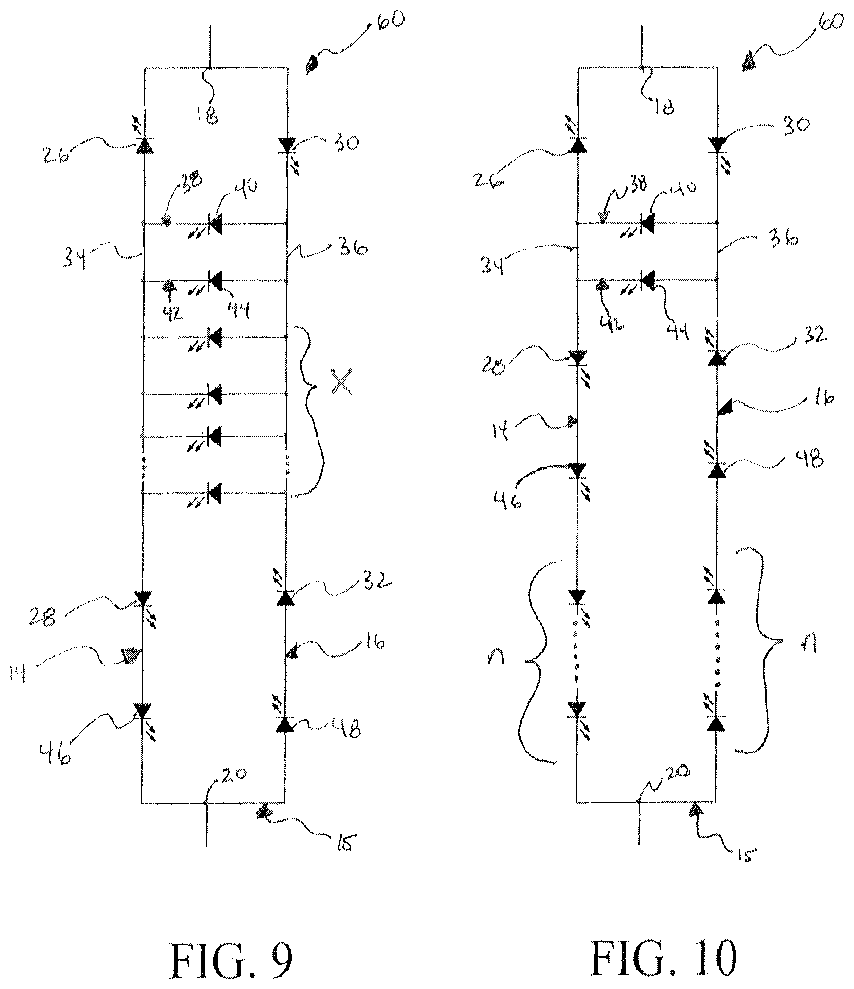
FIG. 9 is a schematic view of an AC-driven LED circuit according to an embodiment of the invention;
FIG. 10 is a schematic view of an AC-driven LED circuit according to an embodiment of the invention;
FIG. 11 is a schematic view of a multi-voltage and/or multi-brightness LED lighting device according to an embodiment of the invention;
FIG. 12 is a schematic view of a multi-voltage and/or multi-brightness LED lighting device integrated within a lamp according to an embodiment of the invention; and
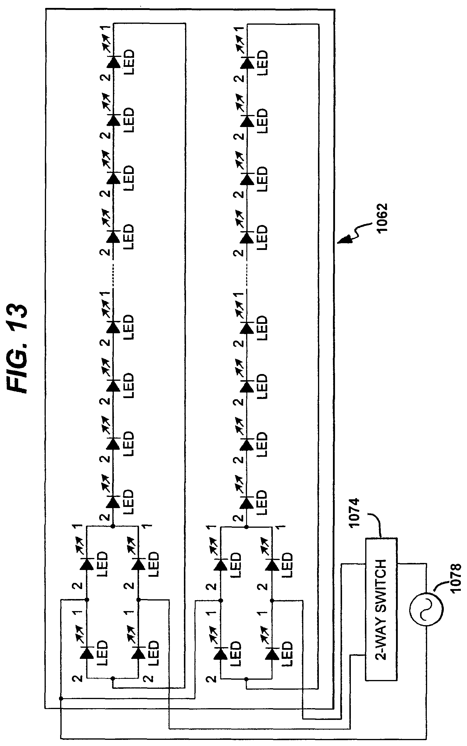
FIG. 13 is a schematic view of a multi-voltage and/or multi-brightness LED lighting device with a switch connected to an AC voltage source, according to an embodiment of the invention.
DETAILED DESCRIPTION OF THE PRESENT INVENTION
While this invention is susceptible to embodiments in many different forms, there are shown in the drawings and will herein be described in detail, preferred embodiments of the invention with the understanding that the present disclosures are to be considered as exemplifications of the principles of the invention and are not intended to limit the broad aspects of the invention to the embodiments illustrated. Like components in the various FIGS. will be given like reference numbers.
FIG. 1 discloses an AC-driven LED circuit 10 including a first parallel circuit 12 having a first branch 14, and a second branch 16. Branches 14, 16 connect at first common point 18 and second common point 20. The common points 18, 20 provide input and output for an AC driving current from a driver 24 for the circuit. The driver may be, for example, mains power, an electronic transformer, or a magnetic transformer.
The first branch 14 has a first LED 26 and a second LED 28, and the second branch 16 having a third LED 30 and a fourth LED 32. The first LED 26 is connected to the second LED 28 in opposing series relationship with the inputs of the first and second LEDs 26, 28 defining a first branch junction 34. The third LED 30 is connected to the fourth LED 32 in opposing series with the outputs of the third and fourth LEDs 30, 32 defining a second branch junction 36.
The first and second branches 14, 16 are connected to one another such that the output of the first LED 26 is connected to the input of the third LED 30 at the first common point 18 and the output of the second LED 28 is connected to the input of the fourth LED 32 at the second common point 20. A first cross-connecting circuit branch 38 has a fifth LED 40. The first cross-connecting circuit branch 38 being configured such that the input of the fifth LED 40 is connected to second branch junction 36 and the output is connected to the first branch junction 34.
As will be appreciated by those of skill in the art, the LED's 26 and 32 will provide light only upon one half of an AC wave, pulse or phase, while LEDs 28 and 30 will provide light only upon the opposite wave, pulse or phase. At lower frequencies, e.g. mains frequencies, if the LEDs are spaced pursuant to another aspect of the invention (disclosed below) at preferably approximately 3.0 mm or less preferably approximately 2.0 mm or less, then the amount of noticeable flicker may not be unacceptable. However, the cross connecting circuit 38 and diode 40 will be on (produce light) in both phases of the AC drive and hence mitigate flicker which may be evidenced in its surrounding LEDs 26, 28, 30 and 32.
FIG. 2 discloses an AC-driven LED circuit 50 which is a modification of AC-driven LED circuit 10. Circuit 50 further mitigates flicker. Circuit 50 provides an additional cross-connecting circuit branch 42 having LED 44. The LEDS 40, 44 are configured such that current flows through each upon both a negative and positive phase of the AC driving source 24. It should be appreciated that according to the invention x number of such cross connecting circuit branches (such as 38, 42) may be added as desired (see for e.g. FIG. 9), however, since the LEDs (such as LEDs 40, 44) are in parallel with each other, their voltage demand will be divided while their current draw will not. Hence a suitable driver need be provided for this circumstance.
To increase the light output of the circuit of the invention, it should be noted as disclosed in FIGS. 3 and 10 that additional or n LEDS may be provided in the branches 14 and 16. Specifically FIG. 3 discloses an AC-driven circuit 60 which is a modification of circuit 50. Circuit 60 provides for additional LEDs 46 and 48. The pair of LEDs are configured among the first and second branch circuits 14, 16 of the parallel circuit 15 such that current flows through the respective diodes 40, 44 upon both a negative and positive phase of the AC driving source 24 and so that the current draw through parallel circuit 15 during both AC phases is substantially the same.
It should be noted that according to the invention, n pairs of LEDs can be configured among first and second branch circuits of a respective parallel circuit (see for e.g., FIG. 10), such that current flows through the respective cross connecting circuit branch LEDs of a parallel circuit upon both a negative and positive phase of the AC driving source and so that the current draw through each of the respective parallel circuits during both AC phases is substantially the same. More LEDs in the branch circuits divide the current from the higher current LEDs in cross connecting circuits 38, 42.
According to another aspect of the invention, to further mitigate the amount of flicker perceived, adding to the light provided and to scalability, additional parallel circuits, each being the same as the first parallel circuit, may be conductively connected to the first parallel circuit in series or parallel at the their common points 18, 20 for providing an input and an output for an AC driving current for the circuit.
For instance, FIG. 4 discloses an AC-driven LED circuit 70 which includes additional parallel circuits 15 connected in series at common points 18, 20. Additionally, as seen in FIG. 5, an AC-driven LED circuit 80 includes additional parallel circuits 15 connected in parallel at common points 18, 20. This embodiment shows the utility of providing a scalable circuit that can be manufactured modularly and used to connect to match higher voltage requirements e.g. circuit 15 may draw drawing 12 V AC while two such circuits 15 in series would meet 24V AC requirements.
Preferably, the number and type of LEDs in the AC-driven LED circuit draws a combined current and combined voltage which is substantially equal to the nominal voltage capacity of the AC drive source.
As shown in FIG. 6, an AC-driven LED assembly 90 has a first and a second LED 84 each discretely packaged, the LEDs being connected in an AC circuit and each LED package 84 being mounted to a substrate 92 at a distance d1 from the other of preferably approximately 3 mm or less, and more preferably 2.0 mm or less. The first and second LEDs may be, for example, discrete packaged semiconductor LED die or LED chips. The AC-driven LED assembly 90 also has packaged LEDs 84 each having a width d2 and a length d3 of preferably approximately 2.5 mm or less, and more preferably 2.0 mm or less.
FIG. 6 discloses an AC-driven LED assembly 90 wherein the LED packages 84 are arranged with respect to each other in a linear spatial relationship, while FIG. 7 discloses an assembly 100 wherein the LED packages 84 are arranged with respect to each other in an XY rectilinear spatial relationship.
As can be seen in FIG. 8, when LED packages 84 are placed at 3 mm or less, the light produced there from intersects, thereby reducing or eliminating the effects of flicker.
Some standard AC voltage in the world include 12V AC, 24V AC, 100V AC, 110V AC, 120V AC, 220V AC, 230V AC, 240V AC and 277V AC. Therefore, it would be advantageous to have a single chip LED or multi-chip single LED packages that could be easily configured to operate at multiple voltages by simply selecting a voltage and/or current level when packaging the multi-voltage and/or multi-current single chip LEDs or by selecting a specific voltage and/or current level when integrating the LED package onto a printed circuit board or within a finished lighting product. It would also be advantageous to have multi-current LED chips and/or packages for LED lamp applications in order to provide a means of increasing brightness in LED lamps by switching in additional circuits just as additional filaments are switched in for standard incandescent lamps.
It would further be advantageous to provide multiple voltage level and/or multiple brightness level light emitting LED circuits, chips, packages and lamps "multi-voltage and/or multi-brightness LED devices" that can easily be electrically configured for at least two forward voltage drive levels with direct AC voltage coupling, bridge rectified AC voltage coupling or constant voltage DC power source coupling. This invention comprises circuits and devices that can be driven with more than one AC or DC forward voltage "multi-voltage" at 6V or greater based on a selectable desired operating voltage level that is achieved by electrically connecting the LED circuits in a series or parallel circuit configuration and/or more than one level of brightness "multi-brightness" based on a switching means that connects and/or disconnects at least one additional LED circuit to and/or from a first LED circuit. The desired operating voltage level and/or the desired brightness level electrical connection may be achieved and/or completed at the LED packaging level when the multi-voltage and/or multi-brightness, circuits and/or single chips are integrated into the LED package, or the LED package may have external electrical contacts that match the integrated multi-voltage and/or multi-brightness circuits and/or single chips within, thus allowing the drive voltage level and/or the brightness level select-ability to be passed on through to the exterior of the LED package and allowing the voltage level or brightness level to be selected at the LED package user, or the PCB assembly facility, or the end product manufacturer.
It would further be advantageous to provide multi-brightness LED devices that can be switched to different levels of brightness by simply switching additional circuits on or off in addition to a first operating circuit within a single chip and or LED package. This would allow LED lamps to switch to higher brightness levels just like 2-way or 3-way incandescent lamps do today.
According to another aspect of the invention a multi-voltage and/or multi-current single chip AC LED and/or multi-voltage and/or multi current AC LED package is integrated within an LED lamp. The LED lamp having a structure that comprises a heat sink, a lens cover and a standard lamp electrical base. The multi-voltage and/or multi-current single chip AC LED and/or package is configured to provide a means of switching on at least one additional single voltage AC LED circuit within multi-voltage and/or multi-current AC LED circuit to provide increased brightness from the LED lamp.
According to another aspect of the invention, at least one single chip multi-current LED bridge circuit is integrated within a LED lamp having a standard lamp base. The single chip multi-current LED bridge circuit may be electrically connected together in parallel configuration but left open to accommodate switching on a switch to the more than one on the single chip and have at least one accessible electrical contact at each opposing end of the two series connected circuits and one accessible electrical contact at the center junction of the at least two individual serially connected LED circuits. The at least two individual circuits are integrated within a single chip.
As would be known to one skilled in the art, various embodiments of the LED packages, substrates, and assemblies may be produced, such as creating an AC-driven circuit where all circuits and LEDs are formed on a semiconductor, where the LED are discretely packaged apart from the circuits, and where each parallel circuit is formed on a printed circuit board.
While in the preceding there has been set forth a preferred embodiment of the invention, it is to be understood that the present invention may be embodied in other specific forms without departing from the spirit or central characteristics thereof. The present embodiments, therefore, are to be considered in all respects as illustrative and not restrictive, and the invention is not to be limited to the details given herein. While specific embodiments have been illustrated and described, numerous modifications come to mind without significantly departing from the characteristics of the invention and the scope of protection is only limited by the scope of the accompanying Claims.
FIG. 11 discloses a schematic diagram of a multi-voltage and/or multi-brightness LED lighting device 1050. The multi-voltage and/or multi-brightness LED lighting device 1050 comprises at least two AC LED circuits 1052, each of which have at least two LEDs 1054 in series and anti-parallel relation. The at leak two AC LED circuits 1052 have at least three electrical contacts 1056 a, 1056 b and 1056 c. The at least two AC LED circuits 1052 are electrically connected together in parallel at one end 1056 a and left unconnected at the opposing ends of the electrical contacts 1056 b and 1056 c. One side of an AC voltage source line is electrically connected to 1056 a and the other side of an AC voltage source line is individually electrically connected to 1056 b and 1056 c with either a fixed connection or a switched connection thereby providing a first brightness when AC voltage is applied to 1056 a and 1056 b and a second brightness when an AC voltage is applied to 1056 a, 1056 b and 1056 c. It is contemplated that the multi-voltage and/or multi-brightness LED lighting device 1050 is a single chip, an LED package, an LED assembly or an LED lamp. The multi-brightness switching capability.
FIG. 12 discloses a schematic diagram similar to the multi-voltage and/or multi-brightness LED device 1050 shown in FIG. 11 integrated within a lamp 1058 and connected to a switch 1060 to control the brightness level of the multi-voltage and/or multi-brightness LED lighting device 1050.
FIG. 13 discloses a schematic diagram the multi-brightness LED lighting device 1062 with a switch 1074 electrically connected between the multi-brightness LED lighting device 1062 and the AC voltage source 1078.
FIG. 13 discloses a schematic diagram of at least two single voltage LED circuits integrated with a single chip or within a substrate and forming a multi-voltage and/or multi-brightness LED device.
A package in certain applications may preferably also include a heat sink, a reflective material, a lens for directing light, phosphor, nano-crystals or other light changing or enhancing substances. In some embodiments, an LED circuit includes at least two LEDs. At least one of the at least two LEDs includes a different phosphor coating than that of at least one other LED of the at least two LEDs. In sum, according to one aspect of the invention, the LED circuits and AC drivers of the present invention permit pre-packaging of the LED portion of a lighting system to be used with standardized drivers of known specified voltage and frequency output. Such packages can be of varied make up and can be combined with each other to create desired systems given the scalable and compatible arrangements possible with, and resulting from, the invention.
According to an aspect of the invention, an LED circuit driver provides a relatively fixed voltage and relatively fixed frequency AC output such as mains power sources. The LED circuit driver output voltage and frequency delivered to the LED circuit may be higher or lower than mains power voltage and frequencies by using an LED circuit inverter driver.
The higher frequency LED circuit Inverter driver may be a electronic transformer, halogen or high intensity discharge (HID) lamp type driver with design modifications for providing a relatively fixed voltage as the LED circuit load changes. Meaning if the LED circuit inverter driver is designed to have an output voltage of 12V LED circuit driver would provide this output as a relatively constant output to a load having one or more than one LED circuits up to the wattage limit of the LED circuit driver even if LED circuits were added to or removed from the output of the LED circuit driver.
* * * * *
D00000
D00001
D00002
D00003
D00004
D00005
XML
uspto.report is an independent third-party trademark research tool that is not affiliated, endorsed, or sponsored by the United States Patent and Trademark Office (USPTO) or any other governmental organization. The information provided by uspto.report is based on publicly available data at the time of writing and is intended for informational purposes only.
While we strive to provide accurate and up-to-date information, we do not guarantee the accuracy, completeness, reliability, or suitability of the information displayed on this site. The use of this site is at your own risk. Any reliance you place on such information is therefore strictly at your own risk.
All official trademark data, including owner information, should be verified by visiting the official USPTO website at www.uspto.gov. This site is not intended to replace professional legal advice and should not be used as a substitute for consulting with a legal professional who is knowledgeable about trademark law.