Stow release assembly for a manually adjustable steering column assembly
Buzzard , et al. December 29, 2
U.S. patent number 10,875,566 [Application Number 15/928,914] was granted by the patent office on 2020-12-29 for stow release assembly for a manually adjustable steering column assembly. This patent grant is currently assigned to Steering Solutions IP Holding Corporation. The grantee listed for this patent is STEERING SOLUTIONS IP HOLDING CORPORATION. Invention is credited to Michael P. Anspaugh, Donald A. Buzzard, Robert C. Derocher, John F. Schulz.


| United States Patent | 10,875,566 |
| Buzzard , et al. | December 29, 2020 |
Stow release assembly for a manually adjustable steering column assembly
Abstract
A stow release assembly for a manually translatable steering column assembly includes an upper jacket. The stow release assembly also includes a lower jacket, the upper jacket translatable relative to the lower jacket, the upper jacket translatable between a retracted range and a stowed range. The stow release assembly further includes an electromechanical blocking element coupled to a stationary component of the steering column assembly and moveable between an extended position and a retracted position, the electromechanical blocking element selectively preventing translation of the upper jacket at a plurality of translation positions.
| Inventors: | Buzzard; Donald A. (Saginaw, MI), Anspaugh; Michael P. (Bay City, MI), Schulz; John F. (Hemlock, MI), Derocher; Robert C. (Essexville, MI) | ||||||||||
|---|---|---|---|---|---|---|---|---|---|---|---|
| Applicant: |
|
||||||||||
| Assignee: | Steering Solutions IP Holding
Corporation (Saginaw, MI) |
||||||||||
| Family ID: | 1000005267807 | ||||||||||
| Appl. No.: | 15/928,914 | ||||||||||
| Filed: | March 22, 2018 |
Prior Publication Data
| Document Identifier | Publication Date | |
|---|---|---|
| US 20190291774 A1 | Sep 26, 2019 | |
| Current U.S. Class: | 1/1 |
| Current CPC Class: | B62D 1/185 (20130101); B62D 1/195 (20130101); B62D 1/184 (20130101); B62D 1/183 (20130101); B62D 1/187 (20130101) |
| Current International Class: | B62D 1/19 (20060101); B62D 1/184 (20060101); B62D 1/183 (20060101); B62D 1/187 (20060101); B62D 1/185 (20060101) |
| Field of Search: | ;74/492,493 ;280/777 |
References Cited [Referenced By]
U.S. Patent Documents
| 2331996 | October 1943 | Maurer |
| 4138167 | February 1979 | Ernst et al. |
| 4315117 | February 1982 | Kokubo et al. |
| 4337967 | July 1982 | Yoshida et al. |
| 4402236 | September 1983 | Nishikawa |
| 4503300 | March 1985 | Lane, Jr. |
| 4503504 | March 1985 | Suzumura et al. |
| 4561323 | December 1985 | Stromberg |
| 4691587 | September 1987 | Farrand et al. |
| 4836566 | June 1989 | Birsching |
| 4921066 | May 1990 | Conley |
| 4962570 | October 1990 | Hosaka et al. |
| 4962944 | October 1990 | Reiche et al. |
| 4967618 | November 1990 | Matsumoto et al. |
| 4976239 | December 1990 | Hosaka |
| 5009120 | April 1991 | Iseler |
| 5186573 | February 1993 | Flotow |
| 5240284 | August 1993 | Takada et al. |
| 5295712 | March 1994 | Omura |
| 5311432 | May 1994 | Momose |
| 5319803 | June 1994 | Allen |
| 5488555 | January 1996 | Asgari |
| 5618058 | April 1997 | Byon |
| 5668721 | September 1997 | Chandy |
| 5690362 | November 1997 | Peitsmeier et al. |
| 5765116 | June 1998 | Wilson-Jones et al. |
| 5820163 | October 1998 | Thacker et al. |
| 5893580 | April 1999 | Hoagland et al. |
| 5911789 | June 1999 | Keipert et al. |
| 6070686 | June 2000 | Pollmann |
| 6170862 | January 2001 | Hoagland et al. |
| 6277571 | May 2001 | Sheng et al. |
| 6301534 | October 2001 | McDermott, Jr. |
| 6354622 | March 2002 | Ulbrich et al. |
| 6360149 | March 2002 | Kwon et al. |
| 6373472 | April 2002 | Palalau et al. |
| 6381526 | April 2002 | Higashi et al. |
| 6390505 | May 2002 | Wilson |
| 6578449 | June 2003 | Anspaugh et al. |
| 6611745 | August 2003 | Paul |
| 6612393 | September 2003 | Bohner et al. |
| 6819990 | November 2004 | Ichinose |
| 7021416 | April 2006 | Kapaan et al. |
| 7048305 | May 2006 | Muller |
| 7062365 | June 2006 | Fei |
| 7295904 | November 2007 | Kanevsky et al. |
| 7308964 | December 2007 | Hara et al. |
| 7428944 | September 2008 | Gerum |
| 7461863 | December 2008 | Muller |
| 7495584 | February 2009 | Sorensen |
| 7628244 | December 2009 | Chino et al. |
| 7665767 | February 2010 | Olgren |
| 7719431 | May 2010 | Bolourchi |
| 7735405 | June 2010 | Parks |
| 7793980 | September 2010 | Fong |
| 7862079 | January 2011 | Fukawatase et al. |
| 7894951 | February 2011 | Norris et al. |
| 7909361 | March 2011 | Oblizajek et al. |
| 8002075 | August 2011 | Markfort |
| 8027767 | September 2011 | Klein et al. |
| 8055409 | November 2011 | Tsuchiya |
| 8069745 | December 2011 | Strieter et al. |
| 8079312 | December 2011 | Long |
| 8146945 | April 2012 | Born et al. |
| 8170725 | May 2012 | Chin et al. |
| 8260482 | September 2012 | Szybalski et al. |
| 8352110 | January 2013 | Szybalski et al. |
| 8479605 | July 2013 | Shavrnoch et al. |
| 8548667 | October 2013 | Kaufmann |
| 8606455 | December 2013 | Boehringer et al. |
| 8634980 | January 2014 | Urmson et al. |
| 8650982 | February 2014 | Matsuno et al. |
| 8670891 | March 2014 | Szybalski et al. |
| 8695750 | April 2014 | Hammond et al. |
| 8818608 | August 2014 | Cullinane et al. |
| 8825258 | September 2014 | Cullinane et al. |
| 8825261 | September 2014 | Szybalski et al. |
| 8843268 | September 2014 | Lathrop et al. |
| 8874301 | October 2014 | Rao et al. |
| 8880287 | November 2014 | Lee et al. |
| 8881861 | November 2014 | Tojo |
| 8899623 | December 2014 | Stadler et al. |
| 8909428 | December 2014 | Lombrozo |
| 8948993 | February 2015 | Schulman et al. |
| 8950543 | February 2015 | Heo et al. |
| 8994521 | March 2015 | Gazit |
| 9002563 | April 2015 | Green et al. |
| 9031729 | May 2015 | Lathrop et al. |
| 9032835 | May 2015 | Davies et al. |
| 9045078 | June 2015 | Tovar et al. |
| 9073574 | July 2015 | Cuddihy et al. |
| 9092093 | July 2015 | Jubner et al. |
| 9108584 | August 2015 | Rao et al. |
| 9134729 | September 2015 | Szybalski et al. |
| 9150200 | October 2015 | Urhahne |
| 9150224 | October 2015 | Yopp |
| 9164619 | October 2015 | Goodlein |
| 9174642 | November 2015 | Wimmer et al. |
| 9186994 | November 2015 | Okuyama et al. |
| 9193375 | November 2015 | Schramm et al. |
| 9199553 | December 2015 | Cuddihy et al. |
| 9227531 | January 2016 | Cuddihy et al. |
| 9233638 | January 2016 | Lisseman et al. |
| 9235111 | January 2016 | Yamaguchi |
| 9235211 | January 2016 | Davidsson et al. |
| 9235987 | January 2016 | Green et al. |
| 9238409 | January 2016 | Lathrop et al. |
| 9248743 | February 2016 | Enthaler et al. |
| 9260130 | February 2016 | Mizuno |
| 9290174 | March 2016 | Zagorski |
| 9290201 | March 2016 | Lombrozo |
| 9298184 | March 2016 | Bartels et al. |
| 9308857 | April 2016 | Lisseman et al. |
| 9308891 | April 2016 | Cudak et al. |
| 9333983 | May 2016 | Lathrop et al. |
| 9352752 | May 2016 | Cullinane et al. |
| 9360865 | June 2016 | Yopp |
| 9630644 | April 2017 | Soderlind |
| 9919724 | March 2018 | Lubischer et al. |
| 10065655 | September 2018 | Bendewald et al. |
| 10144383 | December 2018 | Bodtker et al. |
| 2003/0046012 | March 2003 | Yamaguchi |
| 2003/0094330 | May 2003 | Boloorchi et al. |
| 2003/0227159 | December 2003 | Muller |
| 2004/0016588 | January 2004 | Vitale et al. |
| 2004/0046346 | March 2004 | Eki et al. |
| 2004/0099468 | May 2004 | Chernoff et al. |
| 2004/0129098 | July 2004 | Gayer et al. |
| 2004/0204808 | October 2004 | Satoh et al. |
| 2004/0262063 | December 2004 | Kaufmann et al. |
| 2005/0001445 | January 2005 | Ercolano |
| 2005/0081675 | April 2005 | Oshita et al. |
| 2005/0197746 | September 2005 | Pelchen et al. |
| 2005/0199087 | September 2005 | Li |
| 2005/0275205 | December 2005 | Ahnafield |
| 2006/0005658 | January 2006 | Armstrong |
| 2006/0224287 | October 2006 | Izawa et al. |
| 2006/0244251 | November 2006 | Muller |
| 2007/0021889 | January 2007 | Tsuchiya |
| 2007/0029771 | February 2007 | Haglund et al. |
| 2007/0046003 | March 2007 | Mori et al. |
| 2007/0046013 | March 2007 | Bito et al. |
| 2007/0241548 | October 2007 | Fong |
| 2007/0284867 | December 2007 | Cymbal et al. |
| 2008/0009986 | January 2008 | Lu et al. |
| 2008/0028884 | February 2008 | Monash |
| 2008/0147276 | June 2008 | Pattok et al. |
| 2008/0217901 | September 2008 | Olgren et al. |
| 2008/0229865 | September 2008 | Manwaring |
| 2008/0238068 | October 2008 | Kumar et al. |
| 2009/0024278 | January 2009 | Kondo et al. |
| 2009/0107284 | April 2009 | Lucas et al. |
| 2009/0256342 | October 2009 | Cymbal et al. |
| 2009/0276111 | November 2009 | Wang et al. |
| 2009/0292466 | November 2009 | McCarthy et al. |
| 2010/0152952 | June 2010 | Lee et al. |
| 2010/0222976 | September 2010 | Haug |
| 2010/0228417 | September 2010 | Lee et al. |
| 2010/0228438 | September 2010 | Buerkle |
| 2010/0280713 | November 2010 | Stahlin et al. |
| 2010/0286869 | November 2010 | Katch et al. |
| 2010/0288567 | November 2010 | Bonne |
| 2011/0098922 | April 2011 | Ibrahim |
| 2011/0153160 | June 2011 | Hesseling et al. |
| 2011/0167940 | July 2011 | Shavrnoch et al. |
| 2011/0187518 | August 2011 | Strumolo et al. |
| 2011/0266396 | November 2011 | Abildgaard et al. |
| 2011/0282550 | November 2011 | Tada et al. |
| 2011/0314954 | December 2011 | Matsuno |
| 2012/0024101 | February 2012 | Schnitzer |
| 2012/0136540 | May 2012 | Miller |
| 2012/0205183 | August 2012 | Rombold |
| 2012/0209473 | August 2012 | Birsching et al. |
| 2012/0215377 | August 2012 | Takemura et al. |
| 2013/0002416 | January 2013 | Gazit |
| 2013/0325202 | January 2013 | Howard et al. |
| 2013/0087006 | April 2013 | Ohtsubo et al. |
| 2013/0158771 | June 2013 | Kaufmann |
| 2013/0218396 | August 2013 | Moshchuk et al. |
| 2013/0233117 | September 2013 | Read et al. |
| 2013/0292955 | November 2013 | Higgins et al. |
| 2014/0028008 | January 2014 | Stadler et al. |
| 2014/0046542 | February 2014 | Kauffman et al. |
| 2014/0046547 | February 2014 | Kauffman et al. |
| 2014/0111324 | April 2014 | Lisseman et al. |
| 2014/0277896 | September 2014 | Lathrop et al. |
| 2014/0300479 | October 2014 | Wolter et al. |
| 2014/0309816 | October 2014 | Stefan et al. |
| 2015/0002404 | January 2015 | Hooton |
| 2015/0014086 | January 2015 | Eisenbarth |
| 2015/0032322 | January 2015 | Wimmer et al. |
| 2015/0051780 | January 2015 | Hahne |
| 2015/0120142 | January 2015 | Park et al. |
| 2015/0210273 | February 2015 | Kaufmann et al. |
| 2015/0060185 | March 2015 | Feguri |
| 2015/0246673 | April 2015 | Tseng et al. |
| 2015/0251666 | July 2015 | Attard et al. |
| 2015/0239490 | August 2015 | Sakata |
| 2015/0266499 | September 2015 | Yoshihara |
| 2015/0324111 | September 2015 | Jubner et al. |
| 2015/0283998 | October 2015 | Lind et al. |
| 2015/0375769 | December 2015 | Abboud et al. |
| 2015/0375771 | December 2015 | Tinnin |
| 2016/0009332 | January 2016 | Sirbu |
| 2016/0075371 | March 2016 | Varunkikar et al. |
| 2016/0082867 | March 2016 | Sugioka et al. |
| 2016/0200246 | March 2016 | Lisseman et al. |
| 2016/0159387 | June 2016 | Okano |
| 2016/0185387 | June 2016 | Kuoch |
| 2016/0200343 | June 2016 | Lisseman et al. |
| 2016/0200344 | July 2016 | Sugioka et al. |
| 2016/0207538 | July 2016 | Urano et al. |
| 2016/0209841 | July 2016 | Yamaoka et al. |
| 2016/0229450 | July 2016 | Basting et al. |
| 2016/0231743 | July 2016 | Bendewald et al. |
| 2016/0244070 | August 2016 | Bendewald et al. |
| 2016/0318540 | November 2016 | King |
| 2016/0318542 | November 2016 | Pattok et al. |
| 2016/0347347 | December 2016 | Lubischer et al. |
| 2016/0347348 | December 2016 | Lubischer et al. |
| 2016/0362084 | December 2016 | Martin et al. |
| 2016/0362117 | December 2016 | Kaufmann et al. |
| 2016/0362126 | December 2016 | Lubischer |
| 2016/0368522 | December 2016 | Lubischer |
| 2016/0375860 | December 2016 | Lubischer |
| 2016/0375923 | December 2016 | Schulz et al. |
| 2016/0375925 | December 2016 | Lubischer et al. |
| 2016/0375926 | December 2016 | Lubischer et al. |
| 2016/0375927 | December 2016 | Schulz et al. |
| 2016/0375928 | December 2016 | Magnus |
| 2016/0375929 | December 2016 | Rouleau |
| 2016/0375931 | December 2016 | Lubischer et al. |
| 2017/0029009 | February 2017 | Rouleau |
| 2017/0029018 | February 2017 | Lubischer et al. |
| 2017/0113712 | April 2017 | Watz |
| 2017/0341677 | November 2017 | Buzzard |
| 2018/0072339 | March 2018 | Bodtker |
| 2018/0086378 | March 2018 | Bell et al. |
| 2018/0134308 | May 2018 | Derocher |
| 2018/0148084 | May 2018 | Nash et al. |
| 2018/0251147 | September 2018 | Heitz et al. |
| 2018/0319419 | November 2018 | Kreutz et al. |
| 2018/0370559 | December 2018 | Swamidason |
| 2019/0016365 | January 2019 | Swamidason et al. |
| 1722030 | Jan 2006 | CN | |||
| 1736786 | Feb 2006 | CN | |||
| 101037117 | Sep 2007 | CN | |||
| 101041355 | Sep 2007 | CN | |||
| 101596903 | Dec 2009 | CN | |||
| 102452391 | May 2012 | CN | |||
| 103419840 | Dec 2013 | CN | |||
| 103448785 | Dec 2013 | CN | |||
| 10212782 | Oct 2003 | DE | |||
| 102005032528 | Jan 2007 | DE | |||
| 102005056438 | Jun 2007 | DE | |||
| 102006025254 | Dec 2007 | DE | |||
| 102010025197 | Dec 2011 | DE | |||
| 102015216326 | Sep 2016 | DE | |||
| 1559630 | Aug 2005 | EP | |||
| 1783719 | May 2007 | EP | |||
| 2384946 | Nov 2011 | EP | |||
| 2426030 | Mar 2012 | EP | |||
| 2489577 | Aug 2012 | EP | |||
| 2604487 | Jun 2013 | EP | |||
| 1606149 | May 2014 | EP | |||
| 2862595 | May 2005 | FR | |||
| 3016327 | Jul 2015 | FR | |||
| S60157963 | Aug 1985 | JP | |||
| 2007253809 | Oct 2007 | JP | |||
| 20100063433 | Jun 2010 | KR | |||
| 2006099483 | Sep 2006 | WO | |||
| 2010082394 | Jul 2010 | WO | |||
| 2010116518 | Oct 2010 | WO | |||
Other References
|
English Translation of DE102015216326; ThyssenKrupp; 21 pgs. cited by applicant . Gillespie, Thomas D.; "Fundamentals of Vehicle Dynamics"; Society of Automotive Enginers, Inc.; published 1992; 294 pages. cited by applicant . Kichun, et al.; "Development of Autonomous Car-Part II: A Case Study on the Implementation of an Autonomous Driving System Based on Distributed Architecture"; IEEE Transactions on Industrial Electronics, vol. 62, No. 8, Aug. 2015; 14 pages. cited by applicant . Van der Jagt, Pim; "Prediction of Steering Efforts During Stationary or Slow Rolling Parking Maneuvers"; Ford Forschungszentrum Aachen GmbH.; Oct. 27, 1999; 20 pages. cited by applicant . Varunjikar, Tejas; Design of Horizontal Curves With DownGrades Using Low-Order Vehicle Dynamics Models; A Theisis by T. Varunkikar; 2011; 141 pages. cited by applicant . English translation regarding DE102015216326B4, ThyssenKrupp AG; 21 pgs. cited by applicant. |
Primary Examiner: To; Toan C
Attorney, Agent or Firm: Dickinson Wright PLLC
Claims
Having thus described the invention, it is claimed:
1. A stow release assembly for a manually translatable steering column assembly comprising: an upper jacket; a lower jacket, one of the upper jacket and the lower jacket translatable relative to the other of the lower jacket and the upper jacket over a first telescope range defined by a fully extended position and a first retraction limit, one of the lower jacket and the upper jacket also translatable over a second telescope range defined by the first retraction limit and a second retraction limit; and an electromechanical blocking element coupled to a stationary component of the steering column assembly and moveable between an extended position and a retracted position, the electromechanical blocking element selectively engageable with a first wall of a component operatively coupled to the upper jacket, to prevent retraction of the upper jacket beyond the first retraction limit when the electromechanical blocking element is in the extended position.
2. The stow release assembly of claim 1, further comprising a second wall, engagement of the electromechanical blocking element with the second wall defining the fully extended position.
3. The stow release assembly of claim 1, further comprising a third wall, the electromechanical blocking element selectively engageable with the third wall to prevent retraction of the upper jacket beyond the second retraction limit when the electromechanical blocking element is in the extended position.
4. The stow release assembly of claim 1, wherein the electromechanical blocking element fixing the upper jacket in at least one position between the first retraction limit and the second retraction limit.
5. The stow release assembly of claim 1, wherein the component operatively coupled to the upper jacket is an energy absorption strap.
6. The stow release assembly of claim 1, wherein the upper jacket is coupleable to a steering input device, the steering device switchable between a rotatable condition and a non-rotational condition in at least one position along the first translation range.
7. The stow release assembly of claim 1, wherein the upper jacket is coupleable to a steering input device, the steering device switchable between a rotatable condition and a non-rotational condition in at least one position along the second translation range.
8. The stow release assembly of claim 1, wherein the electromechanical blocking element is spring biased toward the extended position.
9. A stow release assembly for a manually translatable steering column assembly comprising: an upper jacket; a lower jacket, the upper jacket translatable relative to the lower jacket, the upper jacket translatable between a retracted range and a stowed range; and an electromechanical blocking element coupled to a stationary component of the steering column assembly and moveable between an extended position and a retracted position, the electromechanical blocking element selectively preventing translation of the upper jacket at a plurality of translation positions, wherein the plurality of translation positions comprises a fully extended position, a first retraction limit and a second retraction limit, the fully extended position and the first retraction limit defining a first telescope range, the first retraction limit and the second retraction limit defining a second telescope range.
10. The stow release assembly of claim 9, further comprising an energy absorption strap operatively coupled to the upper jacket, the energy absorption strap having first wall selectively engageable with the electromechanical blocking element to define the first retraction limit.
11. The stow release assembly of claim 9, further comprising a second wall of the energy absorption strap, engagement of the electromechanical blocking element with the second wall defining the fully extended position.
12. The stow release assembly of claim 9, further comprising a third wall of the energy absorption strap, the electromechanical blocking element selectively engageable with the third wall to prevent retraction of the upper jacket beyond the second retraction limit when the electromechanical blocking element is in the extended position.
Description
BACKGROUND
As autonomously driven vehicles are developed, a number of opportunities will evolve related to comfort, entertainment and functionality for drivers. Steering wheels are commonly limited to standard driving positions due to the need for a driver to handle the steering wheel during operation of the vehicle. These limitations may be unnecessary during an autonomous driving mode of a vehicle. For example, a steering wheel may be retracted to a stowed position to enlarge the space available to a driver. Many vehicles with stowable columns during autonomous driving utilize power column actuators to move the column into, and away from, the stowed position. However, manually adjusted columns do not typically have stow capability.
SUMMARY OF THE INVENTION
According to one aspect of the disclosure, a stow release assembly for a manually translatable steering column assembly includes an upper jacket. The stow release assembly also includes a lower jacket, one of the upper jacket and the lower jacket translatable relative to the other of the lower jacket and the upper jacket over a first telescope range defined by a fully extended position and a first retraction limit, one of the lower jacket and the upper jacket also translatable over a second telescope range defined by the first retraction limit and a second retraction limit. The stow release assembly further includes an electromechanical blocking element coupled to a stationary component of the steering column assembly and moveable between an extended position and a retracted position, the electromechanical blocking element selectively engageable with a first wall of one of the upper jacket and the lower jacket, or a component operatively coupled to the upper jacket, to prevent retraction of the upper jacket beyond the first retraction limit when the electromechanical blocking element is in the extended position.
According to another aspect of the disclosure, a stow release assembly for a manually translatable steering column assembly includes an upper jacket. The stow release assembly also includes a lower jacket, the upper jacket translatable relative to the lower jacket, the upper jacket translatable between a retracted range and a stowed range. The stow release assembly further includes an electromechanical blocking element coupled to a stationary component of the steering column assembly and moveable between an extended position and a retracted position, the electromechanical blocking element selectively preventing translation of the upper jacket at a plurality of translation positions.
According to another aspect of the disclosure, a stow release assembly for a manually translatable steering column assembly includes an upper jacket. The stow release assembly also includes a lower jacket, one of the upper jacket and the lower jacket moveable relative to the other of the lower jacket and the upper jacket in a raking manner. The stow release assembly further includes a rake blocking element moveable between an engaged condition and a disengaged condition, the engaged condition maintaining one of the upper jacket and the lower jacket in a predefined rake range.
These and other advantages and features will become more apparent from the following description taken in conjunction with the drawings.
BRIEF DESCRIPTION OF THE DRAWINGS
The subject matter which is regarded as the invention is particularly pointed out and distinctly claimed in the claims at the conclusion of the specification. The foregoing and other features, and advantages of the invention are apparent from the following detailed description taken in conjunction with the accompanying drawings in which:
FIG. 1 is an elevational view of a steering column assembly;
FIG. 2 is an elevational view of the steering column assembly in a first position;
FIG. 3 is an elevational view of the steering column assembly in a second position;
FIG. 4 is an elevational view of the steering column assembly in a third position;
FIG. 5 is an enlarged, elevational view of a portion of the steering column assembly in the first position;
FIG. 6 is an enlarged, elevational view of a portion of the steering column assembly in a fully retracted position;
FIG. 7 is a perspective view of a rake control assembly of the steering column assembly;
FIG. 8 is an enlarged, elevational view of a portion of the rake control assembly illustrating a rake blocking element in an engaged condition; and
FIG. 9 is an enlarged, elevational view of a portion of the rake control assembly illustrating the rake blocking element in a disengaged condition.
DETAILED DESCRIPTION
Referring now to the Figures, where the invention will be described with reference to specific embodiments, without limiting same, a steering column assembly with manual stowing capability is disclosed. The embodiments described herein may be employed with various types of steering columns. In particular, autonomous or semi-autonomous driving systems are examples of vehicle steering columns that may benefit from the embodiments disclosed herein. The term autonomous or semi-autonomous refers to vehicles or vehicle sub-systems that are configured to perform operations without continuous input from a driver (e.g., steering, accelerating, braking etc.) and may be equipped with Advanced Driver Assist Steering (ADAS) system(s) to allow the vehicle to be autonomously controlled using sensing, steering, and/or braking technology.
Referring to FIG. 1, the steering column assembly 10 is illustrated. The steering column assembly includes an upper jacket 12 with a steering shaft 16 disposed within a central aperture of the upper jacket 12. The steering shaft 16 is coupleable with a steering input device, such as a steering wheel (not shown). The upper jacket 12 is operatively coupled to a lower jacket 14 in a telescoping manner. In particular, the upper jacket 12 telescopes forwardly toward an instrument panel of the vehicle and rearward toward a seatback that a vehicle operator may be seated in. The steering column assembly 10 may also tilt in a rake motion to adjust the angle at which the steering input device is disposed, relative to a driver. The steering column assembly 10 is operatively coupled, mechanically or electrically, to a steering gear controlled by an ADAS system, for example. At least some components of the steering column assembly 10 are also controlled by the ADAS system in some embodiments.
As discussed above, the upper jacket 12 is telescoping, relative to the lower jacket 12. In particular, the upper jacket 12 is moveable over a first telescope range and a second telescope range. The first range of motion is defined as an un-stowed position of the steering column assembly 10. Over this range of motion, a driver of the vehicle is able to manually steer the vehicle by providing an input command via the steering wheel. Therefore, the steering column assembly 10 is retractable to a first retraction limit in the un-stowed position. This first retraction limit is a typical telescope retraction limit provided by steering column assemblies.
The second telescope range of the steering column assembly 10 allows the upper jacket 12 to be retractable to a second retraction limit that is greater than the above-describe first retraction limit. In other words, the steering column assembly 10 is retractable (i.e., translation away from driver) to a greater extent, relative to the first retraction limit. This degree of retraction is referred to herein as a stowed position of the steering column assembly 10. The second retraction limit may be a completely flush, or even recessed, orientation of the steering input device with the instrument panel. In other embodiments, the second retraction limit is defined by the steering input device being rearward of the instrument panel (i.e., steering wheel closer to the driver than the instrument panel).
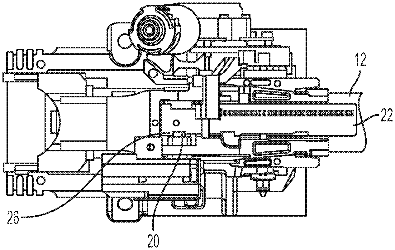
FIGS. 2-4 illustrate the upper jacket 12 in three distinct telescope positions over the first telescope range. FIGS. 2 and 5 illustrate the upper jacket 12 in the position corresponding to the first retraction limit. In this position, the upper jacket 12 is positioned as forwardly as possible in the first telescope range. An electromechanical blocking element 20 is operatively coupled to a stationary structure of the steering column assembly 10. The electromechanical blocking element 20 is moveable between an engaged condition and a disengaged condition. In the illustrated engaged condition, the electromechanical blocking element 20 is disposed within an aperture, slot, recessed feature, or the like 21 defined by a moveable portion of the steering column assembly 10, such as the upper jacket 12 or an energy absorption strap 22 that is coupled to the upper jacket 12 for telescoping movement therewith. In the illustrated embodiment, the electromechanical blocking element 20 is configured to engage one or more features of the energy absorption strap 22. In some embodiments, the electromechanical blocking element 20 is configured to engage one or more features of a frangible device, or some other type of device, permanently affixed to the upper jacket, depending on the design style of the steering column assembly.
In the position shown in FIGS. 2 and 5, the moveable portion(s) of the steering column assembly 10, such as the energy absorption strap 22 and the upper jacket 12 are not permitted to telescope forwardly into the stowed position (i.e., second telescope range). As shown, a first wall 24 of the energy absorption strap 22 is in contact with the electromechanical blocking element 20 to prevent the above-described forward telescoping movement of the upper jacket 12. The first wall 24 defines one end of the aperture, slot, recessed feature or the like 21 of the energy absorption strap 22.
FIG. 3 illustrates the upper jacket 12 in an intermediate position within the first telescope range. The intermediate position refers to a telescope position between the extreme telescope positions of the upper jacket 12 within the first telescope range.
FIG. 4 illustrates the upper jacket 12 in a fully extended position of the first telescope range. In some embodiments, a second wall 26 of the aperture, slot, recessed feature or the like 21 of the energy absorption strap 22 is provided as the feature that limits further rearward extension of the upper jacket 12, or this may be a redundant stop feature. The upper jacket 12 is manually translatable over the first telescope range shown in FIGS. 2-5. This may be done in any suitable manner, including clamping mechanisms actuated by any manual control feature.
As described above in connection with FIGS. 2 and 5, contact between the electromechanical blocking element 20 and the first wall 24 prevents forward movement of the upper jacket forwardly beyond the first telescope limit, out of the first telescope range. To facilitate movement of the upper jacket 12 to the second telescope range (i.e., forwardly beyond the first retraction limit), the electromechanical blocking element 20 must be moved out of engagement with the first wall 24 to a disengaged condition. In the disengaged condition, the electromechanical blocking element 20 is retracted to a position radially outward of the edge of the first wall 24. In this condition, the moveable portion(s) of the steering column assembly 10 are permitted to transition from the un-stowed position to the stowed position, or to intermediate positions therebetween. The electromechanical blocking element 20 is actuated by any suitable mechanism. The element 20 may be cable, linkage, gear, or solenoid driven or actuated, for example. The element 20 is spring biased toward the extended position in some embodiments. In addition to locking or unlocking the steering column assembly 10, the element 20, with corresponding position sensor(s) (not shown), verifies the actual position of the steering column assembly 10, or the degree of engagement of element 20 and thus the position of the steering column steering column assembly 10, in either the stowed or un-stowed position.
FIG. 6 illustrates the steering column assembly 10 in the stowed position at the second retraction limit of the upper jacket 12. This position, and all positions of the second telescope range, are accessible upon retraction of the electromechanical blocking element 20, which allows movement past the first telescope limit as described in detail above. Permissibility of the electromechanical blocking element 20 retraction is dependent upon vehicle control logic, such as via the ADAS system(s), which determines the suitability of the stowed position, taking into account various parameters. The parameters may include, but are not limited to, vehicle speed and vehicle operator conditions.
Once in the second telescope range, the electromechanical blocking element 20 is extended once more to engage a third wall 30 which defines the second retraction limit of the upper jacket 12. This provides an optimized stow position for the steering column assembly 10, with driver reach and hand clearance considerations, that is rearward of a maximum crash stroke position. As described, the electromechanical blocking element 20 prevents forward movement beyond the second retraction limit to define a fully stowed position. In some embodiments, the electromechanical blocking element 20 may be configured to contact an additional feature of the energy absorption strap 22 to block un-stowing of the steering column assembly 10. This may be beneficial if the ADAS system(s) determine that switching to manual steering control is inadvisable.
In some embodiments, there are one or more other discrete positions within the second telescope range at which the electromechanical blocking element 20 fixes the position of the upper jacket 12. Such positions are referred to as stowed when forward of the first retraction limit, but not fully stowed to the second retraction limit. Stowed positions that are not fully stowed sacrifice some of the extra available driver compartment space in order to improve driver access to the steering wheel and/or establish position with a targeted amount of available energy absorbing displacement.
In any of the positions described herein, (stowed, un-stowed, not fully stowed, etc.) multiple options are available regarding the functionality of the steering wheel. For example, the steering wheel may remain in a stationary angular position when the vehicle is in the autonomous driving mode to avoid distraction or inconvenience to the driver. Additionally, the autonomous driving mode may be available in any of the positions.
Referring now to FIGS. 7-9, a rake control assembly 100 is illustrated. The rake control assembly is a guiding feature that establishes a targeted rake adjust position during stowing of the steering column assembly 10. As shown in FIG. 7, a stow lever 102 is used to manually actuate stowing of the steering column assembly 10. Actuation of the stow lever 102 is restricted until the steering column assembly 10 is placed within a defined rake position or zone. The stow lever 102 is part of a mechanism that ratchets or actuates to keep a rake blocking element 104 engaged while the steering column assembly 10 is in the stowed position (or partially stowed position). FIG. 8 illustrates the rake blocking element 104 in an engaged condition and FIG. 9 illustrates the rake blocking element 104 in a disengaged condition.
The mechanism resets when the driver returns the steering column assembly to the first telescope range (i.e., unstowed). Although a fully manual embodiment is illustrated, it is to be appreciated that some embodiments include an electromechanical blocking feature. The controlled rake position, when stowed, simplifies the design of the instrument panel to steering column and steering wheel interfaces and can be used to secure a rake position without the need of high clamp load or a fully locked clamp lever which can be used to minimize time for un-stowing. Additionally, the controlled rake position, when stowed, can be used as a way to verify driver intent to place the steering column assembly 10 into the stowed range. The control allows complete crash stroke, without funneling to a specific rake position when a crash starts from the conventional driving adjustment range.
While the invention has been described in detail in connection with only a limited number of embodiments, it should be readily understood that the invention is not limited to such disclosed embodiments. Rather, the invention can be modified to incorporate any number of variations, alterations, substitutions or equivalent arrangements not heretofore described, but which are commensurate with the spirit and scope of the invention. Additionally, while various embodiments of the invention have been described, it is to be understood that aspects of the invention may include only some of the described embodiments. Accordingly, the invention is not to be seen as limited by the foregoing description.
* * * * *
D00000
D00001
D00002
D00003
D00004
D00005
XML
uspto.report is an independent third-party trademark research tool that is not affiliated, endorsed, or sponsored by the United States Patent and Trademark Office (USPTO) or any other governmental organization. The information provided by uspto.report is based on publicly available data at the time of writing and is intended for informational purposes only.
While we strive to provide accurate and up-to-date information, we do not guarantee the accuracy, completeness, reliability, or suitability of the information displayed on this site. The use of this site is at your own risk. Any reliance you place on such information is therefore strictly at your own risk.
All official trademark data, including owner information, should be verified by visiting the official USPTO website at www.uspto.gov. This site is not intended to replace professional legal advice and should not be used as a substitute for consulting with a legal professional who is knowledgeable about trademark law.