Tissue separating systems and methods
Taylor , et al. December 22, 2
U.S. patent number 10,869,687 [Application Number 15/710,187] was granted by the patent office on 2020-12-22 for tissue separating systems and methods. This patent grant is currently assigned to SPECTRANETICS LLC. The grantee listed for this patent is The Spectranetics Corporation. Invention is credited to Sean Coe, Kenneth D. Harlan, Charles Kennergren, Chris Reiser, Kevin D. Taylor.


View All Diagrams
| United States Patent | 10,869,687 |
| Taylor , et al. | December 22, 2020 |
Tissue separating systems and methods
Abstract
Systems and methods for separating an object such as a pacing lead from a patient tissue involve a flexible and torqueable shaft having an internal lumen sized to receive the object, and a hard separating mechanism for separating the object from the tissue. Typically the shaft and separating mechanism are advanced along or toward the object, and the separating mechanism is contacted with the tissue. The shaft is rotated to effect separation between the object and the tissue. The systems and methods are well suited for use in cardiac pacing or defibrillator lead explant procedures.
| Inventors: | Taylor; Kevin D. (Colorado Springs, CO), Reiser; Chris (Stevenson Ranch, CA), Coe; Sean (Plymouth, MN), Harlan; Kenneth D. (Peyton, CO), Kennergren; Charles (Gothenburg, SE) | ||||||||||
|---|---|---|---|---|---|---|---|---|---|---|---|
| Applicant: |
|
||||||||||
| Assignee: | SPECTRANETICS LLC (Colorado
Springs, CO) |
||||||||||
| Family ID: | 1000005255424 | ||||||||||
| Appl. No.: | 15/710,187 | ||||||||||
| Filed: | September 20, 2017 |
Prior Publication Data
| Document Identifier | Publication Date | |
|---|---|---|
| US 20180008301 A1 | Jan 11, 2018 | |
Related U.S. Patent Documents
| Application Number | Filing Date | Patent Number | Issue Date | ||
|---|---|---|---|---|---|
| 14682779 | Apr 9, 2015 | 9801650 | |||
| 11615005 | May 12, 2015 | 9028520 | |||
| Current U.S. Class: | 1/1 |
| Current CPC Class: | A61B 1/32 (20130101); A61N 1/057 (20130101); A61B 17/3205 (20130101); A61B 17/32002 (20130101); A61N 2001/0578 (20130101); A61B 2017/320044 (20130101); A61B 2017/320056 (20130101) |
| Current International Class: | A61B 17/3205 (20060101); A61B 17/32 (20060101); A61N 1/05 (20060101); A61B 1/32 (20060101) |
References Cited [Referenced By]
U.S. Patent Documents
| 1663761 | March 1928 | Johnson |
| 3400708 | September 1968 | Scheidt |
| 3614953 | October 1971 | Moss |
| 4051596 | October 1977 | Hofmann |
| 4203444 | May 1980 | Bonnell et al. |
| 4246902 | January 1981 | Martinez |
| 4274414 | June 1981 | Johnson et al. |
| 4471777 | September 1984 | McCorkle, Jr. |
| 4517977 | May 1985 | Frost |
| 4582056 | April 1986 | McCorkle et al. |
| 4587972 | May 1986 | Morantte et al. |
| 4598710 | July 1986 | Kleinberg et al. |
| 4646738 | March 1987 | Trott |
| 4662869 | May 1987 | Wright |
| 4674502 | June 1987 | Imonti |
| 4729763 | March 1988 | Henrie |
| 4754755 | July 1988 | Husted |
| 4767403 | August 1988 | Hodge |
| 4790310 | December 1988 | Ginsburg et al. |
| 4943289 | July 1990 | Goode et al. |
| 4950277 | August 1990 | Farr |
| 4988347 | January 1991 | Goode et al. |
| 5009659 | April 1991 | Hamlin et al. |
| 5011482 | April 1991 | Goode et al. |
| 5013310 | May 1991 | Goode et al. |
| 5031634 | July 1991 | Simon |
| 5078723 | January 1992 | Dance et al. |
| 5152744 | October 1992 | Krause et al. |
| 5201316 | April 1993 | Pomeranz et al. |
| 5207683 | May 1993 | Goode et al. |
| 5263928 | November 1993 | Trauthen et al. |
| 5275609 | January 1994 | Pingleton et al. |
| 5290275 | March 1994 | Kittrell et al. |
| 5290303 | March 1994 | Pingleton et al. |
| 5383199 | January 1995 | Laudenslager et al. |
| 5395328 | March 1995 | Ockuly et al. |
| 5423330 | June 1995 | Lee |
| 5456680 | October 1995 | Taylor et al. |
| 5484433 | January 1996 | Taylor et al. |
| 5488958 | February 1996 | Topel |
| 5507751 | April 1996 | Goode et al. |
| 5562694 | October 1996 | Sauer et al. |
| 5569284 | October 1996 | Young et al. |
| 5575797 | November 1996 | Neubauer et al. |
| 5620451 | April 1997 | Rosborough |
| 5632749 | May 1997 | Goode et al. |
| 5643251 | July 1997 | Hillsman et al. |
| 5651781 | July 1997 | Grace |
| 5697936 | December 1997 | Shipko et al. |
| 5697944 | December 1997 | Lary |
| 5718237 | February 1998 | Haaga |
| 5725523 | March 1998 | Mueller |
| 5766164 | June 1998 | Mueller et al. |
| 5782823 | July 1998 | Mueller |
| 5807399 | September 1998 | Laske et al. |
| 5814044 | September 1998 | Hooven |
| 5823971 | October 1998 | Robinson et al. |
| 5824026 | October 1998 | Diaz |
| 5836868 | November 1998 | Ressemann |
| 5863294 | January 1999 | Alden |
| 5873886 | February 1999 | Larsen et al. |
| 5879365 | March 1999 | Whitfield et al. |
| 5893862 | April 1999 | Pratt et al. |
| 5899915 | May 1999 | Saadat |
| 5910150 | June 1999 | Saadat |
| 5931848 | August 1999 | Saadat |
| 5941893 | August 1999 | Saadat |
| 5951581 | September 1999 | Saadat et al. |
| 5972012 | October 1999 | Ream et al. |
| 5980515 | November 1999 | Tu |
| 5980545 | November 1999 | Pacala et al. |
| 6007512 | December 1999 | Hooven |
| 6010476 | January 2000 | Saadat |
| 6019756 | February 2000 | Mueller et al. |
| 6022336 | February 2000 | Zadno-Azizi et al. |
| 6027497 | February 2000 | Daniel et al. |
| 6033402 | March 2000 | Tu et al. |
| 6036685 | March 2000 | Mueller |
| 6051008 | April 2000 | Saadat et al. |
| 6066131 | May 2000 | Mueller et al. |
| 6080175 | June 2000 | Hogendijk |
| 6083237 | July 2000 | Huitema et al. |
| 6099537 | August 2000 | Sugai et al. |
| 6102926 | August 2000 | Tartaglia et al. |
| 6120520 | September 2000 | Saadat et al. |
| 6126654 | October 2000 | Giba et al. |
| 6136005 | October 2000 | Goode et al. |
| 6139543 | October 2000 | Esch et al. |
| 6152909 | November 2000 | Bagaoisan et al. |
| 6152918 | November 2000 | Padilla et al. |
| 6156049 | December 2000 | Lovato et al. |
| 6159203 | December 2000 | Sinofsky |
| 6159225 | December 2000 | Makower |
| 6162214 | December 2000 | Mueller et al. |
| 6165188 | December 2000 | Saadat et al. |
| 6167315 | December 2000 | Coe et al. |
| 6174307 | January 2001 | Daniel et al. |
| 6190352 | February 2001 | Haarala et al. |
| 6190353 | February 2001 | Makower et al. |
| 6203537 | March 2001 | Adrian |
| 6210400 | April 2001 | Hebert et al. |
| 6228076 | May 2001 | Winston et al. |
| 6235044 | May 2001 | Root et al. |
| 6241692 | June 2001 | Tu et al. |
| 6245011 | June 2001 | Dudda et al. |
| 6251121 | June 2001 | Saadat |
| 6258083 | July 2001 | Daniel et al. |
| 6290668 | September 2001 | Gregory et al. |
| 6315774 | November 2001 | Daniel et al. |
| 6324434 | November 2001 | Coe et al. |
| 6342061 | January 2002 | Kauker |
| 6395002 | May 2002 | Ellman et al. |
| 6398773 | June 2002 | Bagaoisan et al. |
| 6402771 | June 2002 | Palmer et al. |
| 6402781 | June 2002 | Langberg et al. |
| 6419674 | July 2002 | Bowser et al. |
| 6419684 | July 2002 | Heisler et al. |
| 6423051 | July 2002 | Kaplan et al. |
| 6428539 | August 2002 | Baxter et al. |
| 6428556 | August 2002 | Chin |
| 6432119 | August 2002 | Saadat |
| 6436054 | August 2002 | Viola et al. |
| 6436114 | August 2002 | Novak et al. |
| 6454741 | September 2002 | Muni et al. |
| 6454758 | September 2002 | Thompson et al. |
| 6461349 | October 2002 | Elbrecht et al. |
| 6478777 | November 2002 | Honeck et al. |
| 6488636 | December 2002 | Bryan et al. |
| 6500182 | December 2002 | Foster |
| 6512959 | January 2003 | Gomperz et al. |
| 6527752 | March 2003 | Bosley et al. |
| 6537314 | March 2003 | Langberg et al. |
| 6554779 | April 2003 | Viola et al. |
| 6558382 | May 2003 | Jahns et al. |
| 6565588 | May 2003 | Clement et al. |
| 6569082 | May 2003 | Chin |
| 6575997 | June 2003 | Palmer et al. |
| 6592607 | July 2003 | Palmer et al. |
| 6595982 | July 2003 | Sekino et al. |
| 6599296 | July 2003 | Gillick et al. |
| 6602241 | August 2003 | Makower et al. |
| 6607547 | August 2003 | Chin |
| 6610046 | August 2003 | Usami et al. |
| 6610066 | August 2003 | Dinger et al. |
| 6613013 | September 2003 | Haarala et al. |
| 6620153 | September 2003 | Mueller et al. |
| 6620160 | September 2003 | Lewis et al. |
| 6620180 | September 2003 | Bays |
| 6641590 | November 2003 | Palmer et al. |
| 6652480 | November 2003 | Imran et al. |
| 6652548 | November 2003 | Evans et al. |
| 6660021 | December 2003 | Palmer et al. |
| 6663626 | December 2003 | Truckai et al. |
| 6669685 | December 2003 | Rizoiu et al. |
| 6673090 | January 2004 | Root et al. |
| 6687548 | February 2004 | Goode |
| 6702813 | March 2004 | Baxter et al. |
| 6706018 | March 2004 | Westlund et al. |
| 6706052 | March 2004 | Chin |
| 6706065 | March 2004 | Langberg et al. |
| 6709456 | March 2004 | Langberg et al. |
| 6712773 | March 2004 | Viola |
| 6712826 | March 2004 | Lui |
| 6772014 | August 2004 | Coe et al. |
| 6802838 | October 2004 | Loeb et al. |
| 6805692 | October 2004 | Muni et al. |
| 6810882 | November 2004 | Langberg et al. |
| 6818001 | November 2004 | Wulfman et al. |
| 6860860 | March 2005 | Viola |
| 6871085 | March 2005 | Sommer |
| 6884240 | April 2005 | Dykes |
| 6887238 | May 2005 | Jahns et al. |
| 6893450 | May 2005 | Foster |
| 6913612 | July 2005 | Palmer et al. |
| 6962585 | November 2005 | Poleo et al. |
| 6979290 | December 2005 | Mourlas et al. |
| 6979319 | December 2005 | Manning et al. |
| 6989028 | January 2006 | Lashinski et al. |
| 6999809 | February 2006 | Currier et al. |
| 7004956 | February 2006 | Palmer et al. |
| 7008434 | March 2006 | Kurz et al. |
| 7011682 | March 2006 | Lashinski et al. |
| 7033335 | April 2006 | Haarala et al. |
| 7033344 | April 2006 | Imran |
| 7033357 | April 2006 | Baxter et al. |
| 7060061 | June 2006 | Altshuler et al. |
| 7063693 | June 2006 | Guenst |
| 7077856 | July 2006 | Whitman |
| 7092765 | August 2006 | Geske et al. |
| 7104983 | September 2006 | Grasso et al. |
| 7114642 | October 2006 | Whitman |
| 7117039 | October 2006 | Manning et al. |
| 7149587 | December 2006 | Wardle et al. |
| 7151965 | December 2006 | Osypka |
| 7189207 | March 2007 | Viola |
| 7191015 | March 2007 | Lamson et al. |
| 7192430 | March 2007 | Truckai et al. |
| 7204824 | April 2007 | Moulis |
| 7214180 | May 2007 | Chin |
| 7226459 | June 2007 | Cesarini et al. |
| 7238179 | July 2007 | Brucker et al. |
| 7238180 | July 2007 | Mester et al. |
| 7252641 | August 2007 | Thompson et al. |
| 7264587 | September 2007 | Chin |
| 7273478 | September 2007 | Appling et al. |
| 7276052 | October 2007 | Kobayashi et al. |
| 7288096 | October 2007 | Chin |
| 7296577 | November 2007 | Lashinski et al. |
| 7306588 | December 2007 | Loeb et al. |
| 7326226 | February 2008 | Root et al. |
| 7328071 | February 2008 | Stehr et al. |
| 7344546 | March 2008 | Wulfman et al. |
| 7357794 | April 2008 | Makower et al. |
| 7359756 | April 2008 | Goode |
| 7369901 | May 2008 | Morgan et al. |
| 7392095 | June 2008 | Flynn et al. |
| 7396354 | July 2008 | Rychnovsky et al. |
| 7398781 | July 2008 | Chin |
| 7449010 | November 2008 | Hayase et al. |
| 7462167 | December 2008 | Kratz et al. |
| 7485127 | February 2009 | Nistal |
| 7494484 | February 2009 | Beck et al. |
| 7507252 | March 2009 | Lashinski et al. |
| 7509169 | March 2009 | Eigler et al. |
| 7510576 | March 2009 | Langberg et al. |
| 7513877 | April 2009 | Viola |
| 7513892 | April 2009 | Haarala et al. |
| 7526342 | April 2009 | Chin et al. |
| 7537602 | May 2009 | Whitman |
| 7540865 | June 2009 | Griffin et al. |
| 7544197 | June 2009 | Kelsch et al. |
| 7559941 | July 2009 | Zannis et al. |
| D600792 | September 2009 | Eubanks et al. |
| 7591790 | September 2009 | Pflueger |
| 7597698 | October 2009 | Chin |
| 7606615 | October 2009 | Makower et al. |
| 7611474 | November 2009 | Hibner et al. |
| 7637904 | December 2009 | Wingler et al. |
| 7645286 | January 2010 | Catanese et al. |
| 7648466 | January 2010 | Stephens et al. |
| 7651503 | January 2010 | Coe et al. |
| 7651504 | January 2010 | Goode et al. |
| D610259 | February 2010 | Way et al. |
| D611146 | March 2010 | Way et al. |
| 7674272 | March 2010 | Torrance et al. |
| 7695485 | April 2010 | Whitman et al. |
| 7695512 | April 2010 | Lashinski et al. |
| 7697996 | April 2010 | Manning et al. |
| 7713231 | May 2010 | Wulfman et al. |
| 7713235 | May 2010 | Torrance et al. |
| 7713281 | May 2010 | Leeflang et al. |
| 7722549 | May 2010 | Nakao |
| 7740626 | June 2010 | Takayama et al. |
| 7743960 | June 2010 | Whitman et al. |
| D619252 | July 2010 | Way et al. |
| D619253 | July 2010 | Way et al. |
| 7758594 | July 2010 | Lamson et al. |
| 7758613 | July 2010 | Whitman |
| D621939 | August 2010 | Way et al. |
| 7766923 | August 2010 | Catanese et al. |
| 7780650 | August 2010 | Frassica et al. |
| 7780682 | August 2010 | Catanese et al. |
| 7780694 | August 2010 | Palmer et al. |
| 7794411 | September 2010 | Ritchart et al. |
| 7798813 | September 2010 | Harrel |
| 7803151 | September 2010 | Whitman |
| 7806835 | October 2010 | Hibner et al. |
| 7811281 | October 2010 | Rentrop |
| 7815655 | October 2010 | Catanese et al. |
| 7842009 | November 2010 | Torrance et al. |
| 7845538 | December 2010 | Whitman |
| 7858038 | December 2010 | Andreyko et al. |
| 7875018 | January 2011 | Tockman et al. |
| 7875049 | January 2011 | Eversull et al. |
| 7890186 | February 2011 | Wardle et al. |
| 7890192 | February 2011 | Kelsch et al. |
| 7896879 | March 2011 | Solsberg et al. |
| 7896891 | March 2011 | Catanese et al. |
| 7905889 | March 2011 | Catanese et al. |
| 7909836 | March 2011 | McLean et al. |
| 7914464 | March 2011 | Burdorff et al. |
| 7914542 | March 2011 | Lamson et al. |
| D635671 | April 2011 | Way et al. |
| 7918230 | April 2011 | Whitman et al. |
| 7918803 | April 2011 | Ritchart et al. |
| 7930040 | April 2011 | Kelsch et al. |
| 7935146 | May 2011 | Langberg et al. |
| 7938786 | May 2011 | Ritchie et al. |
| 7942830 | May 2011 | Solsberg et al. |
| 7951071 | May 2011 | Whitman et al. |
| 7951158 | May 2011 | Catanese et al. |
| 7963040 | June 2011 | Shan et al. |
| 7963433 | June 2011 | Whitman et al. |
| 7974710 | July 2011 | Seifert |
| 7981049 | July 2011 | Ritchie et al. |
| 7981050 | July 2011 | Ritchart et al. |
| 7981128 | July 2011 | To et al. |
| 7988726 | August 2011 | Langberg et al. |
| 7991258 | August 2011 | Temelkuran et al. |
| 7992758 | August 2011 | Whitman et al. |
| 7993350 | August 2011 | Ventura et al. |
| 7993351 | August 2011 | Worley et al. |
| 7993359 | August 2011 | Atwell et al. |
| 8007469 | August 2011 | Duffy |
| 8007488 | August 2011 | Ravenscroft |
| 8007503 | August 2011 | Catanese et al. |
| 8007506 | August 2011 | To et al. |
| 8016748 | September 2011 | Mourlas et al. |
| 8016844 | September 2011 | Privitera et al. |
| 8016855 | September 2011 | Whitman et al. |
| 8016858 | September 2011 | Whitman |
| 8021373 | September 2011 | Whitman et al. |
| 8025199 | September 2011 | Whitman et al. |
| 8043309 | October 2011 | Catanese et al. |
| RE42959 | November 2011 | Saadat et al. |
| 8052616 | November 2011 | Andrisek et al. |
| 8052659 | November 2011 | Ravenscroft et al. |
| 8056786 | November 2011 | Whitman et al. |
| 8056791 | November 2011 | Whitman |
| 8070762 | December 2011 | Escudero et al. |
| 8090430 | January 2012 | Makower et al. |
| 8097012 | January 2012 | Kagarise |
| 8100920 | January 2012 | Gambale et al. |
| 8118208 | February 2012 | Whitman |
| 8126570 | February 2012 | Manning et al. |
| 8128577 | March 2012 | Viola |
| 8128636 | March 2012 | Lui et al. |
| 8133214 | March 2012 | Hayase et al. |
| 8137377 | March 2012 | Palmer et al. |
| 8142442 | March 2012 | Palmer et al. |
| 8142446 | March 2012 | Shan |
| RE43300 | April 2012 | Saadat et al. |
| 8157815 | April 2012 | Catanese et al. |
| 8186559 | May 2012 | Whitman |
| 8187204 | May 2012 | Miller et al. |
| 8192430 | June 2012 | Goode et al. |
| 8202229 | June 2012 | Miller et al. |
| 8206409 | June 2012 | Privitera et al. |
| 8211118 | July 2012 | Catanese et al. |
| 8216254 | July 2012 | McLean et al. |
| 8235916 | August 2012 | Whiting et al. |
| 8236016 | August 2012 | To et al. |
| 8239039 | August 2012 | Zarembo et al. |
| 8241272 | August 2012 | Arnold et al. |
| 8251916 | August 2012 | Speeg et al. |
| 8252015 | August 2012 | Leeflang et al. |
| 8257312 | September 2012 | Duffy |
| 8272554 | September 2012 | Whitman et al. |
| 8273078 | September 2012 | Muenker |
| 8295947 | October 2012 | Lamson et al. |
| 8303511 | November 2012 | Eigler et al. |
| 8323240 | December 2012 | Wulfman et al. |
| 8326437 | December 2012 | Cully et al. |
| 8333740 | December 2012 | Shippert |
| 8333776 | December 2012 | Cheng et al. |
| 8337516 | December 2012 | Escudero et al. |
| 8343167 | January 2013 | Henson |
| 8343187 | January 2013 | Lamson et al. |
| 8353899 | January 2013 | Wells et al. |
| 8361094 | January 2013 | To et al. |
| 8361097 | January 2013 | Patel et al. |
| 8364280 | January 2013 | Marnfeldt et al. |
| 8372098 | February 2013 | Tran |
| 8394110 | March 2013 | Catanese et al. |
| 8394113 | March 2013 | Wei et al. |
| 8425535 | April 2013 | McLean et al. |
| 9028520 | May 2015 | Taylor et al. |
| 9345508 | May 2016 | Hendrick |
| 9801650 | October 2017 | Taylor et al. |
| 2001/0005789 | June 2001 | Root et al. |
| 2001/0016717 | August 2001 | Haarala et al. |
| 2001/0025174 | September 2001 | Daniel et al. |
| 2001/0031981 | October 2001 | Evans et al. |
| 2001/0039427 | November 2001 | Dinger et al. |
| 2001/0041899 | November 2001 | Foster |
| 2001/0044568 | November 2001 | Langberg et al. |
| 2002/0002372 | January 2002 | Jahns et al. |
| 2002/0007204 | January 2002 | Goode |
| 2002/0010475 | January 2002 | Lui |
| 2002/0010487 | January 2002 | Evans et al. |
| 2002/0016628 | February 2002 | Langberg et al. |
| 2002/0045811 | April 2002 | Kittrell et al. |
| 2002/0065543 | May 2002 | Gomperz et al. |
| 2002/0068954 | June 2002 | Foster |
| 2002/0087151 | July 2002 | Mody et al. |
| 2002/0103477 | August 2002 | Grasso et al. |
| 2002/0103532 | August 2002 | Langberg et al. |
| 2002/0103533 | August 2002 | Langberg et al. |
| 2002/0123785 | September 2002 | Zhang et al. |
| 2002/0151961 | October 2002 | Lashinski et al. |
| 2002/0183735 | December 2002 | Edwards et al. |
| 2002/0188278 | December 2002 | Tockman et al. |
| 2003/0009146 | January 2003 | Muni et al. |
| 2003/0036788 | February 2003 | Coe et al. |
| 2003/0050630 | March 2003 | Mody et al. |
| 2003/0050631 | March 2003 | Mody et al. |
| 2003/0055444 | March 2003 | Evans et al. |
| 2003/0055445 | March 2003 | Evans et al. |
| 2003/0069575 | April 2003 | Chin et al. |
| 2003/0073985 | April 2003 | Mueller et al. |
| 2003/0078562 | April 2003 | Makower et al. |
| 2003/0105451 | June 2003 | Westlund et al. |
| 2003/0125619 | July 2003 | Manning et al. |
| 2003/0167056 | September 2003 | Jahns et al. |
| 2003/0187460 | October 2003 | Chin et al. |
| 2003/0187461 | October 2003 | Chin |
| 2003/0199921 | October 2003 | Palmer et al. |
| 2003/0204202 | October 2003 | Palmer et al. |
| 2003/0208209 | November 2003 | Gambale et al. |
| 2003/0229323 | December 2003 | Haarala et al. |
| 2003/0229353 | December 2003 | Cragg |
| 2004/0006358 | January 2004 | Wulfman et al. |
| 2004/0010248 | January 2004 | Appling et al. |
| 2004/0015193 | January 2004 | Lamson et al. |
| 2004/0019359 | January 2004 | Worley et al. |
| 2004/0049208 | March 2004 | Hill et al. |
| 2004/0054368 | March 2004 | Truckai et al. |
| 2004/0054388 | March 2004 | Osypka |
| 2004/0059348 | March 2004 | Geske et al. |
| 2004/0064024 | April 2004 | Sommer |
| 2004/0068256 | April 2004 | Rizoiu et al. |
| 2004/0068288 | April 2004 | Palmer et al. |
| 2004/0093016 | May 2004 | Root et al. |
| 2004/0097788 | May 2004 | Mourlas et al. |
| 2004/0102804 | May 2004 | Chin |
| 2004/0102841 | May 2004 | Langberg et al. |
| 2004/0111101 | June 2004 | Chin |
| 2004/0116939 | June 2004 | Goode |
| 2004/0116992 | June 2004 | Wardle et al. |
| 2004/0133220 | July 2004 | Lashinski et al. |
| 2004/0138562 | July 2004 | Makower et al. |
| 2004/0138744 | July 2004 | Lashinski et al. |
| 2004/0143284 | July 2004 | Chin |
| 2004/0147911 | July 2004 | Sinofsky |
| 2004/0147912 | July 2004 | Sinofsky |
| 2004/0147913 | July 2004 | Sinofsky |
| 2004/0153096 | August 2004 | Goode et al. |
| 2004/0153098 | August 2004 | Chin et al. |
| 2004/0153146 | August 2004 | Lashinski et al. |
| 2004/0172116 | September 2004 | Seifert et al. |
| 2004/0176840 | September 2004 | Langberg et al. |
| 2004/0181249 | September 2004 | Torrance et al. |
| 2004/0199191 | October 2004 | Schwartz |
| 2004/0216748 | November 2004 | Chin |
| 2004/0220519 | November 2004 | Wulfman et al. |
| 2004/0230212 | November 2004 | Wulfman |
| 2004/0230213 | November 2004 | Wulfman et al. |
| 2004/0235611 | November 2004 | Nistal |
| 2004/0236312 | November 2004 | Nistal et al. |
| 2004/0236397 | November 2004 | Coe et al. |
| 2004/0243123 | December 2004 | Grasso et al. |
| 2004/0243162 | December 2004 | Wulfman et al. |
| 2004/0254534 | December 2004 | Bjorkman et al. |
| 2004/0260322 | December 2004 | Rudko et al. |
| 2004/0267276 | December 2004 | Camino et al. |
| 2004/0267304 | December 2004 | Zannis et al. |
| 2005/0004644 | January 2005 | Kelsch et al. |
| 2005/0025798 | February 2005 | Moulis |
| 2005/0027337 | February 2005 | Rudko et al. |
| 2005/0038419 | February 2005 | Arnold et al. |
| 2005/0060030 | March 2005 | Lashinski et al. |
| 2005/0065561 | March 2005 | Manning et al. |
| 2005/0090748 | April 2005 | Makower et al. |
| 2005/0096740 | May 2005 | Langberg et al. |
| 2005/0131399 | June 2005 | Loeb et al. |
| 2005/0149104 | July 2005 | Leeflang et al. |
| 2005/0149105 | July 2005 | Leeflang et al. |
| 2005/0197623 | September 2005 | Leeflang et al. |
| 2005/0222607 | October 2005 | Palmer et al. |
| 2005/0228402 | October 2005 | Hofmann |
| 2005/0228452 | October 2005 | Mourlas et al. |
| 2005/0251116 | November 2005 | Steinke et al. |
| 2005/0259942 | November 2005 | Temelkuran et al. |
| 2005/0267557 | December 2005 | Flynn et al. |
| 2005/0273090 | December 2005 | Nieman et al. |
| 2005/0283143 | December 2005 | Rizoiu |
| 2005/0288596 | December 2005 | Eigler et al. |
| 2005/0288604 | December 2005 | Eigler et al. |
| 2005/0288654 | December 2005 | Nieman et al. |
| 2005/0288722 | December 2005 | Eigler et al. |
| 2006/0041250 | February 2006 | Poleo |
| 2006/0052660 | March 2006 | Chin |
| 2006/0084839 | April 2006 | Mourlas et al. |
| 2006/0100663 | May 2006 | Palmer et al. |
| 2006/0116746 | June 2006 | Chin |
| 2006/0116757 | June 2006 | Lashinski et al. |
| 2006/0167417 | July 2006 | Kratz et al. |
| 2006/0173440 | August 2006 | Lamson et al. |
| 2006/0217755 | September 2006 | Eversull et al. |
| 2006/0229490 | October 2006 | Chin |
| 2006/0235431 | October 2006 | Goode et al. |
| 2006/0247751 | November 2006 | Seifert |
| 2006/0253179 | November 2006 | Goode et al. |
| 2006/0265042 | November 2006 | Catanese et al. |
| 2006/0276871 | December 2006 | Lamson et al. |
| 2006/0287574 | December 2006 | Chin |
| 2007/0005084 | January 2007 | Clague et al. |
| 2007/0015964 | January 2007 | Eversull et al. |
| 2007/0016130 | January 2007 | Leeflang et al. |
| 2007/0021812 | January 2007 | Manning et al. |
| 2007/0049929 | March 2007 | Catanese et al. |
| 2007/0050003 | March 2007 | Zarembo et al. |
| 2007/0083217 | April 2007 | Eversull et al. |
| 2007/0100410 | May 2007 | Lamson et al. |
| 2007/0106328 | May 2007 | Wardle et al. |
| 2007/0129710 | June 2007 | Rudko et al. |
| 2007/0142846 | June 2007 | Catanese et al. |
| 2007/0197861 | August 2007 | Reiley et al. |
| 2007/0198020 | August 2007 | Reiley et al. |
| 2007/0232981 | October 2007 | Ravenscroft et al. |
| 2007/0265648 | November 2007 | Cohen |
| 2007/0276412 | November 2007 | Catanese et al. |
| 2007/0293853 | December 2007 | Truckai et al. |
| 2008/0004643 | January 2008 | To et al. |
| 2008/0004644 | January 2008 | To et al. |
| 2008/0004645 | January 2008 | To et al. |
| 2008/0004646 | January 2008 | To et al. |
| 2008/0004647 | January 2008 | To et al. |
| 2008/0015625 | January 2008 | Ventura et al. |
| 2008/0021484 | January 2008 | Catanese et al. |
| 2008/0021485 | January 2008 | Catanese et al. |
| 2008/0033232 | February 2008 | Catanese et al. |
| 2008/0033456 | February 2008 | Catanese et al. |
| 2008/0033458 | February 2008 | McLean et al. |
| 2008/0033488 | February 2008 | Catanese et al. |
| 2008/0039833 | February 2008 | Catanese et al. |
| 2008/0039872 | February 2008 | Catanese et al. |
| 2008/0039874 | February 2008 | Catanese et al. |
| 2008/0039875 | February 2008 | Catanese et al. |
| 2008/0039876 | February 2008 | Catanese et al. |
| 2008/0039889 | February 2008 | Lamson et al. |
| 2008/0039893 | February 2008 | McLean et al. |
| 2008/0039894 | February 2008 | Catanese et al. |
| 2008/0045986 | February 2008 | To et al. |
| 2008/0051756 | February 2008 | Makower et al. |
| 2008/0058759 | March 2008 | Makower et al. |
| 2008/0071341 | March 2008 | Goode et al. |
| 2008/0071342 | March 2008 | Goode et al. |
| 2008/0097426 | April 2008 | Root et al. |
| 2008/0103439 | May 2008 | Torrance et al. |
| 2008/0103446 | May 2008 | Torrance et al. |
| 2008/0103516 | May 2008 | Wulfman et al. |
| 2008/0125748 | May 2008 | Patel |
| 2008/0147061 | June 2008 | Goode et al. |
| 2008/0154293 | June 2008 | Taylor |
| 2008/0183163 | July 2008 | Lampropoulos et al. |
| 2008/0208105 | August 2008 | Zelickson et al. |
| 2008/0221560 | September 2008 | Arai et al. |
| 2008/0228208 | September 2008 | Wulfman et al. |
| 2008/0249516 | October 2008 | Muenker |
| 2008/0262516 | October 2008 | Gambale et al. |
| 2008/0275497 | November 2008 | Palmer et al. |
| 2008/0275498 | November 2008 | Palmer et al. |
| 2008/0281308 | November 2008 | Neuberger et al. |
| 2008/0287888 | November 2008 | Ravenscroft |
| 2008/0306333 | December 2008 | Chin |
| 2009/0012510 | January 2009 | Bertolero et al. |
| 2009/0018523 | January 2009 | Lamson et al. |
| 2009/0018553 | January 2009 | McLean et al. |
| 2009/0018565 | January 2009 | To et al. |
| 2009/0034927 | February 2009 | Temelkuran et al. |
| 2009/0036871 | February 2009 | Hayase et al. |
| 2009/0054918 | February 2009 | Henson |
| 2009/0060977 | March 2009 | Lamson et al. |
| 2009/0071012 | March 2009 | Shan et al. |
| 2009/0076522 | March 2009 | Shan |
| 2009/0131907 | May 2009 | Chin et al. |
| 2009/0157045 | June 2009 | Haarala et al. |
| 2009/0192439 | July 2009 | Lamson et al. |
| 2009/0204128 | August 2009 | Lamson et al. |
| 2009/0221994 | September 2009 | Neuberger et al. |
| 2009/0222025 | September 2009 | Catanese et al. |
| 2009/0227999 | September 2009 | Willis et al. |
| 2009/0234378 | September 2009 | Escudero et al. |
| 2010/0004606 | January 2010 | Hansen et al. |
| 2010/0016836 | January 2010 | Makower et al. |
| 2010/0030154 | February 2010 | Duffy |
| 2010/0030161 | February 2010 | Duffy |
| 2010/0030247 | February 2010 | Pikus et al. |
| 2010/0030262 | February 2010 | McLean et al. |
| 2010/0030263 | February 2010 | Cheng et al. |
| 2010/0049225 | February 2010 | To et al. |
| 2010/0063488 | March 2010 | Fischer et al. |
| 2010/0125253 | May 2010 | Olson et al. |
| 2010/0137873 | June 2010 | Grady et al. |
| 2010/0160952 | June 2010 | Leeflang et al. |
| 2010/0191165 | July 2010 | Appling et al. |
| 2010/0198194 | August 2010 | Manning et al. |
| 2010/0198229 | August 2010 | Olomutzki et al. |
| 2010/0217277 | August 2010 | Truong |
| 2010/0222737 | September 2010 | Arnold et al. |
| 2010/0222787 | September 2010 | Goode et al. |
| 2010/0240951 | September 2010 | Catanese et al. |
| 2010/0256616 | October 2010 | Katoh et al. |
| 2010/0280496 | November 2010 | Shippert |
| 2010/0324472 | December 2010 | Wulfman |
| 2010/0331793 | December 2010 | Tulleken |
| 2011/0004238 | January 2011 | Palmer et al. |
| 2011/0009957 | January 2011 | Langberg et al. |
| 2011/0022057 | January 2011 | Eigler et al. |
| 2011/0028959 | February 2011 | Chasan |
| 2011/0034790 | February 2011 | Mourlas et al. |
| 2011/0040238 | February 2011 | Wulfman et al. |
| 2011/0040312 | February 2011 | Lamson et al. |
| 2011/0040315 | February 2011 | To et al. |
| 2011/0040326 | February 2011 | Wei et al. |
| 2011/0046648 | February 2011 | Johnston et al. |
| 2011/0054493 | March 2011 | McLean et al. |
| 2011/0060349 | March 2011 | Cheng et al. |
| 2011/0071440 | March 2011 | Torrance et al. |
| 2011/0105947 | May 2011 | Fritscher-Ravens et al. |
| 2011/0106004 | May 2011 | Eubanks et al. |
| 2011/0106099 | May 2011 | Duffy et al. |
| 2011/0112548 | May 2011 | Fifer et al. |
| 2011/0112562 | May 2011 | Torrance |
| 2011/0112563 | May 2011 | To et al. |
| 2011/0112564 | May 2011 | Wolf |
| 2011/0118660 | May 2011 | Torrance et al. |
| 2011/0144423 | June 2011 | Tong et al. |
| 2011/0144425 | June 2011 | Catanese et al. |
| 2011/0151463 | June 2011 | Wulfman |
| 2011/0152607 | June 2011 | Catanese et al. |
| 2011/0152906 | June 2011 | Escudero et al. |
| 2011/0152907 | June 2011 | Escudero et al. |
| 2011/0160747 | June 2011 | McLean et al. |
| 2011/0160748 | June 2011 | Catanese et al. |
| 2011/0166564 | July 2011 | Merrick et al. |
| 2011/0178543 | July 2011 | Chin et al. |
| 2011/0190758 | August 2011 | Lamson et al. |
| 2011/0196298 | August 2011 | Anderson et al. |
| 2011/0196355 | August 2011 | Mitchell et al. |
| 2011/0208207 | August 2011 | Bowe et al. |
| 2011/0213398 | September 2011 | Chin et al. |
| 2011/0218528 | September 2011 | Ogata et al. |
| 2011/0238078 | September 2011 | Goode et al. |
| 2011/0238102 | September 2011 | Gutfinger et al. |
| 2011/0245751 | October 2011 | Hofmann |
| 2011/0251629 | October 2011 | Galdonik et al. |
| 2011/0257592 | October 2011 | Ventura et al. |
| 2011/0270169 | November 2011 | Gardeski et al. |
| 2011/0270170 | November 2011 | Gardeski et al. |
| 2011/0270289 | November 2011 | To et al. |
| 2011/0300010 | December 2011 | Jarnagin et al. |
| 2011/0301417 | December 2011 | Mourlas et al. |
| 2011/0301626 | December 2011 | To et al. |
| 2012/0035590 | February 2012 | Whiting et al. |
| 2012/0041422 | February 2012 | Whiting et al. |
| 2012/0053564 | March 2012 | Ravenscroft |
| 2012/0065659 | March 2012 | To |
| 2012/0083810 | April 2012 | Escudero et al. |
| 2012/0083826 | April 2012 | Chao et al. |
| 2012/0095447 | April 2012 | Fojtik |
| 2012/0095479 | April 2012 | Bowe et al. |
| 2012/0097174 | April 2012 | Spotnitz et al. |
| 2012/0123411 | May 2012 | Ibrahim et al. |
| 2012/0136341 | May 2012 | Appling et al. |
| 2012/0165827 | June 2012 | Khairkhahan et al. |
| 2012/0165861 | June 2012 | Palmer et al. |
| 2012/0191015 | July 2012 | Zannis et al. |
| 2012/0209173 | August 2012 | Hayase et al. |
| 2012/0215305 | August 2012 | Le et al. |
| 2012/0239008 | September 2012 | Fojtik |
| 2012/0245600 | September 2012 | McLean et al. |
| 2012/0253229 | October 2012 | Cage |
| 2012/0265183 | October 2012 | Tulleken et al. |
| 2012/0323252 | December 2012 | Booker |
| 2012/0323253 | December 2012 | Garai et al. |
| 2012/0330292 | December 2012 | Shadduck et al. |
| 2013/0006228 | January 2013 | Johnson et al. |
| 2013/0035676 | February 2013 | Mitchell et al. |
| 2013/0096582 | April 2013 | Cheng et al. |
| 2013/0103047 | April 2013 | Steingisser et al. |
| 2014/0031800 | January 2014 | Ben Oren et al. |
| 2015/0216547 | August 2015 | Hendrick |
| 2016/0317173 | November 2016 | Hendrick |
| H05506382 | Sep 1993 | JP | |||
| 2004516073 | Jun 2004 | JP | |||
| 1991017711 | Nov 1991 | WO | |||
| 1995033513 | Dec 1995 | WO | |||
| 1999007295 | Feb 1999 | WO | |||
| 1999049937 | Oct 1999 | WO | |||
| 1999058066 | Nov 1999 | WO | |||
| 2001076680 | Oct 2001 | WO | |||
| 2002049690 | May 2003 | WO | |||
| 2004080345 | Sep 2004 | WO | |||
| 2004080507 | Sep 2004 | WO | |||
| 2006007410 | Jan 2006 | WO | |||
| 2008005888 | Jan 2008 | WO | |||
| 2008005891 | Jan 2008 | WO | |||
| 2008042987 | Apr 2008 | WO | |||
| 2009005779 | Jan 2009 | WO | |||
| 2009054968 | Apr 2009 | WO | |||
| 2009065082 | May 2009 | WO | |||
| 2009126309 | Oct 2009 | WO | |||
| 2011003113 | Jan 2011 | WO | |||
| 2011084863 | Jul 2011 | WO | |||
| 2011133941 | Oct 2011 | WO | |||
| 2011162595 | Dec 2011 | WO | |||
| 2012009697 | Apr 2012 | WO | |||
| 2012098335 | Jul 2012 | WO | |||
| 2012114333 | Aug 2012 | WO | |||
| 2012177117 | Dec 2012 | WO | |||
| 2013036588 | Mar 2013 | WO | |||
Other References
|
US. Appl. No. 62/005,315 entitled Surgical Instrument for Removing an Implanted Object filed May 30, 2014. cited by applicant . U.S. Appl. No. 62/058,790 entitled Medical Device for Removing an Implanted Object filed Oct. 2, 2014. cited by applicant . U.S. Appl. No. 62/094,808 entitled Multiple Configuration Surgical Cutting Device filed Dec. 19, 2014. cited by applicant . U.S. Appl. No. 62/113,865 entitled Medical Device for Removing an Implanted Object filed Feb. 9, 2015. cited by applicant . Decision to Grant for European Patent Application No. 07255018.9, dated Aug. 8, 2013, 2 pages. cited by applicant . Department of Health and Ageing in Australian Government, "Horizon Scanning Technology Prioritising: Laser Extraction Systems." 2010. 15 pages. cited by applicant . EP extended Search Report dated Oct. 21, 2009; Application No. 07255019.7, 8 pages. cited by applicant . Extended European Search Report for European Application No. 07255018.9, dated Nov. 12, 2010, 7 pages. cited by applicant . Final Action for U.S. Appl. No. 11/615,005, dated Nov. 9, 2009, 10 pages. cited by applicant . Final Action for U.S. Appl. No. 11/615,005, dated Nov. 21, 2013, 20 pages. cited by applicant . Final Action for U.S. Appl. No. 11/615,006 dated Oct. 26, 2009, 9 pages. cited by applicant . Intent to Grant for European Patent Application No. 07255018.9, dated Nov. 29, 2012, 7 pages. cited by applicant . International Search Report and Written Opinion for International Patent Application No. PCT/US2013/059434, dated Dec. 13, 2013, 14 pages. cited by applicant . International Search Report and Written Opinion issued in PCT/US2014/019258, dated Aug. 8, 2014, 21 pages. cited by applicant . International Search Report and Written Opinion issued in PCT/US2014/021167 dated Jun. 26, 2014, 19 pages. cited by applicant . International Search Report and Written Opinion issued in PCT/US2014/026496 dated Jul. 30, 2014, 16 pages. cited by applicant . International Search Report and Written Opinion issued in PCT/US2015/016899, dated May 1, 2015, 14 pages. cited by applicant . Notice of Allowance for European Patent Application No. 07255018.9, dated Jul. 26, 2012, 47 pages. cited by applicant . Notice of Allowance for Japan Patent Application No. 2007-333273, dated Jan. 16, 2014, 3 pages. cited by applicant . Official Action for European Patent Application No. 07255018.9, dated Jul. 19, 2011, 3 pages. cited by applicant . Official Action for U.S. Appl. No. 11/615,005, dated Apr. 16, 2009, 13 pages. cited by applicant . Official Action for U.S. Appl. No. 11/615,005, dated Feb. 11, 2011, 12 pages. cited by applicant . Official Action for U.S. Appl. No. 11/615,005, dated Jul. 21, 2010, 10 pages. cited by applicant . Official Action for U.S. Appl. No. 11/615,005, dated Mar. 14, 2013, 16 pages. cited by applicant . Official Action for U.S. Appl. No. 13/800,728, dated Jan. 16, 2014, 14 pages. cited by applicant . Official Action for U.S. Appl. No. 11/615,006 dated Apr. 24, 2009, 7 pages. cited by applicant . Official Action for U.S. Appl. No. 11/615,006 dated Feb. 17, 2010, 8 pages. cited by applicant . Official Action for U.S. Appl. No. 11/615,006 dated Jul. 20, 2010, 9 pages. cited by applicant . Official Action for U.S. Appl. No. 11/615,006 dated Mar. 14, 2013, 16 pages. cited by applicant . Official Action for U.S. Appl. No. 11/615,006 dated Nov. 22, 2013, 16 pages. cited by applicant . Official Action with English translation for Japan Patent Application No. 2007-333173, dated Apr. 30, 2013, 5 pages. cited by applicant . Official Action with English translation for Japan Patent Application No. 2007-333173, dated Aug. 13, 2012, 7 pages. cited by applicant . Official Action with English translation for Japan Patent Application No. 2007-333273, dated Jul. 30, 2012, 7 pages. cited by applicant . Official Action with English translation for Japan Patent Application No. 2007-333273, dated Jun. 6, 2013, 10 pages. cited by applicant . PCT Application No. PCT/US2015/016899 entitled Medical Device for Removing an Implanted Object filed Feb. 20, 2015. cited by applicant . PCT Application No. PCT/US2015/018305 entitled Multiple Configuration Surgical Cutting Device filed Mar. 2, 2015. cited by applicant . U.S. Appl. No. 13/800,651 entitled System and Method of Ablative Cutting and Pulsed Vacuum Aspiration, filed Mar. 13, 2013. cited by applicant . U.S. Appl. No. 13/800,675 entitled Laser Catheter With Helical Internal Lumen, filed Mar. 13, 2013. cited by applicant . U.S. Appl. No. 13/800,700 entitled Device and Method of Ablative Cutting With Helical Tip, filed Mar. 13, 2013. cited by applicant . U.S. Appl. No. 13/800,728 entitled Laser Ablation Catheter, filed Mar. 13, 2013. cited by applicant . U.S. Appl. No. 13/828,231 entitled Tissue Slitting Methods and Systems, filed Mar. 14, 2013. cited by applicant . U.S. Appl. No. 13/828,310 entitled Tissue Slitting Methods and Systems, filed Mar. 14, 2013. cited by applicant . U.S. Appl. No. 13/828,383 entitled Tissue Slitting Methods and Systems, filed Mar. 14, 2013. cited by applicant . U.S. Appl. No. 13/828,441 entitled Tissue Slitting Methods and Systems, filed Mar. 14, 2013. cited by applicant . U.S. Appl. No. 13/828,536 entitled Expandable Lead Jacket, filed Mar. 14, 2013. cited by applicant . U.S. Appl. No. 13/828,638 entitled Lead Removal Sleeve, filed Mar. 14, 2013. cited by applicant . U.S. Appl. No. 13/834,405 entitled Retractable Blade for Lead Removal Device, filed Mar. 15, 2013. cited by applicant . U.S. Appl. No. 14/577,976 entitled Surgical Instrument Including an Inwardly Deflecting Cutting Tip for Removing an Implanted Object filed Dec. 19, 2014. cited by applicant . U.S. Appl. No. 14/589,688 entitled Retractable Separating Systems and Methods filed Jan. 5, 2015. cited by applicant . U.S. Appl. No. 14/627,851 entitled Medical Device for Removing an Implanted Object filed Feb. 20, 2015. cited by applicant . U.S. Appl. No. 14/627,950 entitled Medical Device for Removing an Implanted Object filed Feb. 20, 2015. cited by applicant . U.S. Appl. No. 14/635,742 entitled Multiple Configuration Surgical Cutting Device filed Mar. 2, 2015. cited by applicant . U.S. Appl. No. 61/793,597 entitled Surgical Instrument for Removing an Implanted Object filed Mar. 15, 2013. cited by applicant . U.S. Appl. No. 61/987,993 entitled Dual Mode Mechanical Catheter Cutting System filed May 2, 2014. cited by applicant. |
Primary Examiner: Lynch; Robert A
Parent Case Text
CROSS-REFERENCES TO RELATED APPLICATIONS
This application is a continuation of U.S. application Ser. No. 14/682,779, filed Apr. 9, 2015, now U.S. Pat. No. 9,801,650, and titled "TISSUE SEPARATING SYSTEMS AND METHODS," which is a continuation of U.S. patent application Ser. No. 11/615,005, filed Dec. 22, 2006, now U.S. Pat. No. 9,028,520, and titled "TISSUE SEPARATING SYSTEMS AND METHODS," the entire contents of which are incorporated herein by reference for all purposes. This application is related to U.S. patent application Ser. No. 11/615,006, filed Dec. 22, 2006, now U.S. Pat. No. 8,961,551, and titled "RETRACTABLE SEPARATING SYSTEMS AND METHODS," the entire contents of which are incorporated herein by reference for all purposes.
Claims
What is claimed is:
1. A system for separating an object from a patient tissue, comprising: a sheath having a proximal end and a distal end; and a cylindrical separator coupled with the distal end of the sheath, the separator having an internal lumen, an upper side, a lower side, a proximal end, and a distal end having a separating mechanism, wherein the internal lumen of the separator defines a central longitudinal axis and is sized to receive the object, wherein the distal end of the separating mechanism comprises a distal face oriented at an acute angle relative to the central longitudinal axis and extending in a planar fashion from the upper side to the lower side such that an entire diameter of the internal lumen is open at the distal face, wherein the distal face comprises an abrasive material, wherein the distal face is configured such that whereupon being pressed against patient tissue, the separating mechanism does not separate patient tissue, and whereupon rotating the separating mechanism, the separating mechanism separates patient tissue.
2. The system according to claim 1, wherein the abrasive material comprises a member selected from the group consisting of a diamond, an aluminum carbide, and a silica carbide.
3. The system according to claim 2, wherein the acute angle is within a range from about 30 degrees to about 85 degrees.
4. The system according to claim 3, wherein the member is a first member, and wherein the separator comprises a second member selected from the group consisting of a cutting member, a dilating member, and a stripping member.
5. The system according to claim 2, wherein the member is a first member, and wherein the separator comprises a second member selected from the group consisting of a cutting member, a dilating member, and a stripping member.
6. The system according to claim 1, wherein the acute angle is within a range from about 30 degrees to about 85 degrees.
7. The system according to claim 6, wherein the separator comprises a member selected from the group consisting of a cutting member, a dilating member, and a stripping member.
8. The system according to claim 1, wherein the separator comprises a member selected from the group consisting of a cutting member, a dilating member, and a stripping member.
9. A system for separating an object from a patient tissue, comprising: sheath having a proximal end and a distal end; and a cylindrical separator coupled with the distal end of the sheath, the separator having an internal lumen sized to receive the object, a proximal end, a distal end, and a longitudinal axis, wherein the distal end has a rim, wherein the rim comprises a first portion and a second portion, wherein the distal end comprises a distal face disposed at an acute angle relative to the longitudinal axis such that an entire diameter of the internal lumen is open at the distal face, wherein the first portion comprises a separating mechanism and the second portion comprises a blunt edge, wherein the separating mechanism is configured such that whereupon the distal end being pressed against patient tissue, the second portion does not separate patient tissue, and whereupon rotating the separating mechanism, the first portion separates patient tissue.
10. The system according to claim 9, wherein the separating mechanism comprises abrasive material.
11. The system according to claim 9, wherein the separating mechanism comprises a blade.
Description
BACKGROUND OF THE INVENTION
The present application relates generally to systems and methods for separating tissue in a patient, and more specifically, to techniques for separating pacing leads from a patient.
Cardiac pacing systems typically include a pacemaker and a pacing lead, which are placed inside the body of a patient. The pacemaker includes a power source and circuitry configured to send timed electrical pulses to the pacing lead. The pacing lead carries the electrical pulse to the heart to initiate a heartbeat, and transmits information about the heart's electrical activity to the pacemaker. The pacing lead can include a fixation mechanism that holds the lead to the cardiac tissue. In some cases, a pacing lead is inserted through a vein and guided into a heart chamber where it is attached with the heart. In other instances, a pacing lead is attached to the outside of the heart. A common problem associated with pacing leads is the development of scar tissue or adhesions where the pacing lead contacts the patient's body tissue. Patient tissue can become attached with the pacing lead, and thus removal or extraction of the pacing lead may present complications.
Current pacing lead extraction techniques include mechanical traction, mechanical devices, and laser devices. Mechanical traction is often accomplished by inserting a locking stylet into the lead and pulling to remove it. In some cases, for example where mechanical traction is ineffective, dilating telescopic sheaths can be used to strip away the scar tissue adhering the lead to the body. Unfortunately, metal sheaths that are currently used to strip scar tissue from implanted leads often cannot traverse the tortuous lead path, and in many instances can only be used in proximal locations. Currently used plastic sheaths may be able to access certain distal lead locations, but often suffer from poor torque properties, low radiopacity, and ineffective penetration into hard tissue because they have soft tips that deform when in contact with the hard tissue. Dilation techniques often involve pushing tissue away from the lead when the sheath is pushed longitudinally along the lead. However, longitudinal forces can be easily lost during the procedure by tortuousity or curvature in the lead and by friction encountered within the anatomy or over the pacing lead. Longitudinal forces also may require heavy counter traction on the lead-that can result in pacing lead breakage. Some mechanical sheaths have proposed trigger mechanisms for extending a blade from a sheath. At least some of these devices, however, involve complicated activation mechanisms and may not be well suited for negotiating the tortuous paths that exist in certain vascular or physiological environments. Laser devices typically employ laser energy to cut the scar tissue away from the lead thus allowing for removal. Although effective in some circumstances for removing chronic implanted pacing leads, many laser systems can be expensive and unaffordable to many treatment centers.
What is needed are improved mechanical devices and methods for extracting pacing leads as well as other objects. These techniques can provide effective alternatives to currently used dilating lead extraction sheaths and laser systems.
BRIEF SUMMARY OF THE INVENTION
Advantageously, embodiments of the present invention encompass separating devices having improved separating surfaces and shapes that are well suited for freeing pacing leads from adherent scar tissue. For example, a separating tip or element can provide a bevel or angle to enhance contact between a separating tip blade and the patient tissue during rotation of the tip. In some cases, a separating tip provides a separating surface that can be lightly forced against a tissue without separating the tissue, and that can separate the tissue when pressed more forcefully against the tissue or when rotated relative to the tissue. Separating systems can be configured to extract pacing leads primarily by torque. An exemplary separating system involves a torqueable and flexible polymer sheath with a durable, radiopaque tip section that includes hard plastic or metal. The shaft can be composed of a braided composite construction to provide flexibility along with a 1:1 torque response. The system may also include a handle to allow for improved rotation capabilities. When the sheath is rotated, a cutting tip can strip, dilate, or cut adhered tissue from the lead in an axial manner. The configurations provided herein allow pacing lead extraction under reduced force, thereby minimizing the incidence of lead breakage and protecting the safety of the patient. By combining such torque characteristics with distal surface cutting edges, it is possible to effectively penetrate resistant scar tissue when necessary, while maintaining a safe, non-separating profile when the sheath is advanced longitudinally over a pacing lead.
Many of the embodiments described herein refer to cutting elements, cutting assemblies, cutters, and the like, which often include items for cutting tissue, however it is understood that these cutting features can be replaced with or referred to as stripping or dilating elements, stripping or dilating assemblies, or strippers or dilators. Similarly, these cutting features may be referred to as separating elements, separating assemblies, or separators. Stripping features can include items for stripping tissue from pacing leads and other objects within the body of a patient. Relatedly, dilating features can include items for dilating tissue surrounding or near pacing leads and other objects within the body of a patient. Cutting features or procedures can be used or referred to interchangeably with stripping features or procedures, and with dilating features or procedures. Methods that include stripping or dilating tissue may or may not include cutting tissue. In some embodiments, cutting, stripping, or dilating elements or procedures, or any combinations thereof, may be referred to as separating elements or procedures. For example, a separator may refer to or encompass a cutter, a stripper, or a dilator, or any combination thereof. The separating devices, sheath configurations, and other systems and methods described herein are well suited for use with retractable lead extraction techniques disclosed in previously incorporated U.S. patent application Ser. No. 11/605,006, filed Dec. 22, 2006 (Retractable Separating Systems and Methods). Such separating and retractable extraction devices can be used in conjunction with lead locking devices in an explant procedure. In an exemplary method, a lead is disconnected from a pacemaker, and a lead locking device is inserted into or coupled with the lead. A separating or retractable extraction system can be placed over the lead and the lead locking device, and advanced distally so as to separate tissue that is attached with or surrounding the lead. Lead locking devices are often useful in providing traction with a pacing or defibrillator lead without breaking or damaging the lead.
In a first aspect, embodiments of the present invention provide a system for separating an object from a patient tissue. The system can include a sheath having a proximal end and a distal end. The system can also include a cylindrical separator coupled with the distal end of the sheath. The separator can have an internal lumen, a proximal end, and a distal end having a separating mechanism. The separating mechanism can include an abrasive material. In some cases, the abrasive material includes diamond, aluminum carbide, silica carbide, or the like. The distal end of the separator can define a plane, and the internal lumen of the separator can define a central longitudinal axis. An acute angle between the plane and the central longitudinal axis can be within a range from about 10 degrees to about 65 degrees or from about 30 degrees to about 85 degrees. The separator may include a cutting member, a dilating member, a stripping member, or the like.
In another aspect, embodiments of the present invention provide a system for separating an object from a patient tissue, where the system includes an internal sheath having a proximal end and a distal end, an external sheath having a proximal end and a distal end, an internal separator coupled with the distal end of the internal sheath, the internal separator having a first separating mechanism, and an external separator coupled with the distal end of the external sheath, the external separator having a second separating mechanism. The internal separator can be disposed at least partially within the external separator, and the internal and external separators can be configured for relative rotational movement that brings the first separating mechanism and the second separating mechanism together. In some cases, the internal separator includes an internal cutting member, an internal stripping member, an internal dilating member, or the like, and the external separator includes an external cutting member, an external stripping member, an external dilating member, or the like. In some aspects, the first separating mechanism includes a first cutting blade, a first stripping blade, a first dilating blade, or the like, and the second separating mechanism includes a second cutting blade, a second stripping blade, a second dilating blade, or the like. In another aspect, embodiments provide a separating system that includes a sheath having a distal end, and a cylindrical separator. The separator can include a distal end having a separating mechanism, and a proximal end coupled with the sheath distal end. The distal end of the cylindrical separator can define a plane that is substantially perpendicular to a central longitudinal axis of the cylindrical separator. In some cases, the sheath includes a proximal end that is less flexible than the distal end of the sheath. The distal end of the sheath can have bending stiffness less than about 6 lb/in. The sheath can have a torsional transmission of greater than about 0.177 pound-inch. In some embodiments, the sheath includes a braid. The separator can include a cutting member, a stripping member, a dilating member, or the like. The separating mechanism can include a cutting blade, a stripping blade, a dilating blade, or the like.
In another aspect, embodiments of the present invention provide a system for separating an object from a patient tissue that includes a sheath having a proximal end and a distal end, and a cylindrical separator coupled with the distal end of the sheath. The separator can have an internal lumen, a proximal end, and a distal end. The distal end of the separator can define a plane, and can include plurality of teeth having separating means in perpendicular alignment with the plane or in alignment with a central longitudinal axis of the sheath. The internal lumen of the separator can define a central longitudinal axis, and an acute angle between the plane and the central longitudinal axis can be within a range from about 30 degrees to about 85 degrees.
In another aspect, embodiments of the present invention provide a system for separating an object from a patient tissue. The system can include a sheath having a distal end, and a cylindrical separator having a proximal end, a distal end, and an internal lumen that defines a central longitudinal axis. The proximal end of the separator can be coupled to the distal end of the sheath, and the distal end of the separator can include a rim that defines a plane which is not perpendicular to the central longitudinal axis of the separator, a separating mechanism disposed along a first portion of the rim, and a blunt edge disposed along a second portion of the rim. In some cases, the separating mechanism can be configured to separate the object from the tissue when the separator is rotated in one direction, but not when the separator is rotated in an opposite direction. The separating mechanism can be a cutting blade, a stripping blade, a dilating blade, or the like. In another aspect, embodiments of the present invention provide a system for separating an object from a patient tissue. The system can include a flexible shaft having a proximal end and a distal end, and a metal separator having a proximal end, a distal end, and an internal lumen that defines a central longitudinal axis. The proximal end of the separator can be coupled to the distal end of the sheath, and the distal end of the separator can include a separating means and can define a plane which is not perpendicular to the central longitudinal axis of the separator. The proximal end of the flexible shaft may be less or more flexible than the distal end of the shaft. In some cases, the distal end of the flexible shaft has a bending stiffness less than about 6 lb/in. In some cases, the flexible shaft has a torsional transmission of greater than about 0.177 pound-inch. In some cases, the flexible shaft includes a braid. In many cases, the separating mechanism is configured to separate the object from the patient tissue when the separator is rotated.
In still another aspect, embodiments of the present invention provide a system for separating an object from a patient tissue. The system includes a flexible shaft having a proximal end, a distal end, and an internal lumen having an inner diameter greater than about 0.130 inch. The shaft can have a bending stiffness of less than about 6 lb/in and a torsional transmission of greater than about 0.177 pound-inch. The system may also include a separator having a proximal end and a distal end. The proximal end of the separator can be coupled to the distal end of the sheath, the distal end of the separator can include a separating mechanism, and the separating mechanism can have a hardness greater than about B65 Rockwell. In yet another aspect, embodiments of the present invention provide a method for separating a patient tissue from an object. The method can include providing a tool that has a sheath having a proximal end and a distal end, and a separator operably coupled to the distal end of the sheath. The separator can have a proximal end, a distal end that includes a rim, a separating mechanism disposed along a first portion of the rim, a blunt edge disposed along a second portion of the rim, and an internal lumen that defines a central longitudinal axis. The method can include contacting the separating mechanism with patient tissue that is attached to the object. The method can also include rotating the separator so as to separate the tissue from the object with the separating mechanism. In some cases, the rim defines a plane that is not perpendicular to the central longitudinal axis of the separator. In some cases, the rim defines a plane that is perpendicular to the central longitudinal axis of the separator. In some cases, the separating mechanism can be configured to separate the tissue from the object when the separator is rotated in one direction, but not when the separator is rotated in an opposite direction.
In still another aspect, embodiments of the present invention provide a system for separating an object from a patient tissue. The system can include a sheath having a distal end. The system can also include a cylindrical separator having a proximal end, a distal end, and an internal lumen that defines a central longitudinal axis. The proximal end of the separator can be coupled to the distal end of the sheath, and the distal end of the separator can include a rim that defines a plane, a separating mechanism disposed along a first portion of the rim, and a blunt edge disposed along a second portion of the rim. In some cases, the plane is substantially perpendicular to the central longitudinal axis of the separator. In some cases, the plane is not substantially perpendicular to the central longitudinal axis of the separator. Optionally, an acute angle between the plane and the central longitudinal axis can be within a range from about 30 degrees to about 85 degrees.
For a fuller understanding of the nature and advantages of the present invention, reference should be had to the ensuing detailed description taken in conjunction with the accompanying drawings.
BRIEF DESCRIPTION OF THE DRAWINGS
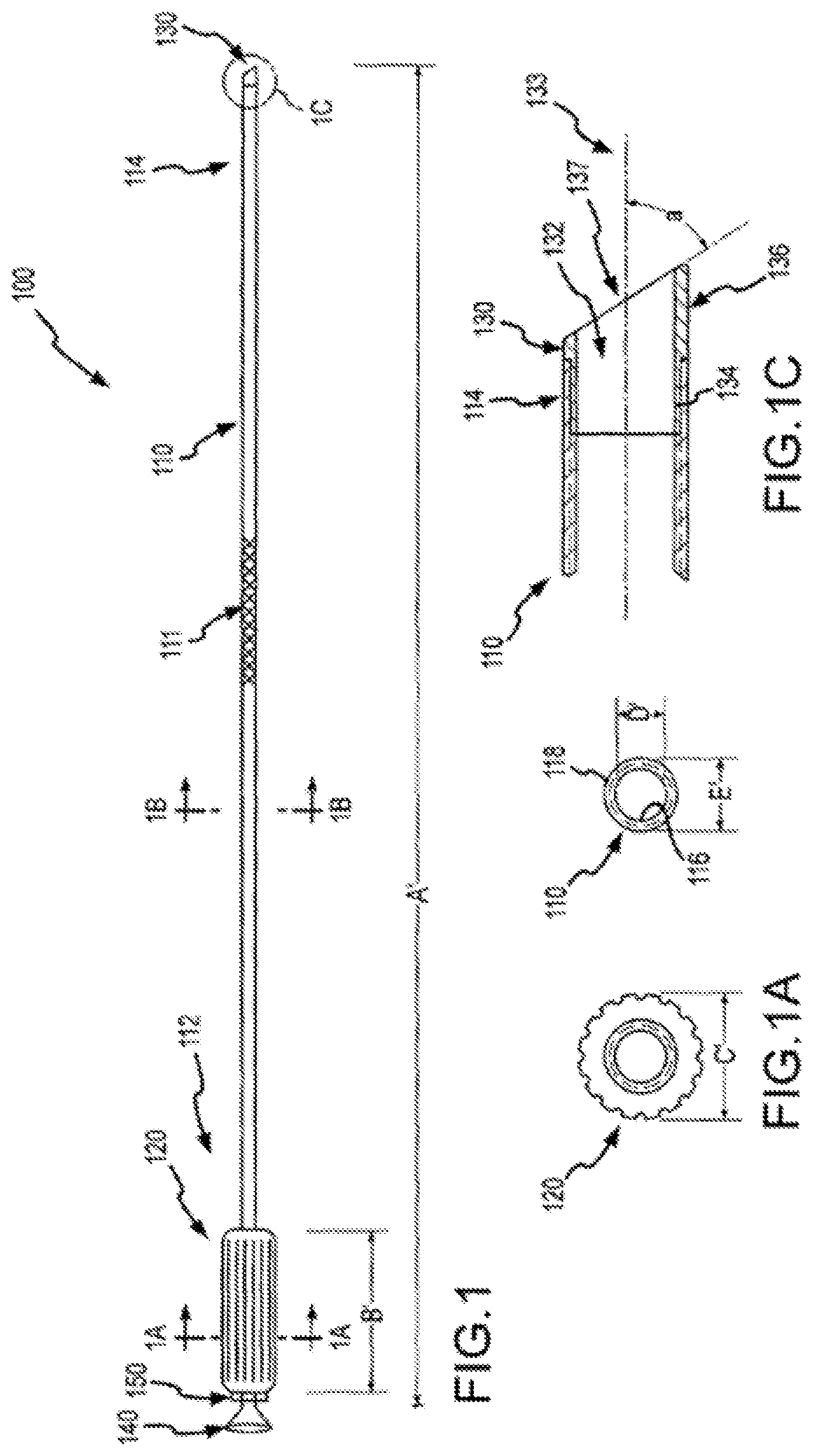
FIG. 1 shows a system for separating an object from a patient tissue according to embodiments of the present invention.
FIG. 1A illustrates a cross section of a handle according to embodiments of the present invention.
FIG. 1B depicts a cross section of a sheath according to embodiments of the present invention.
FIG. 1C shows a cross section of a distal portion of a separating system according to embodiments of the present invention.
FIG. 2A shows a system for separating an object from a patient tissue according to embodiments of the present invention.
FIG. 2B shows a cross section of a sheath combination according to embodiments of the present invention.
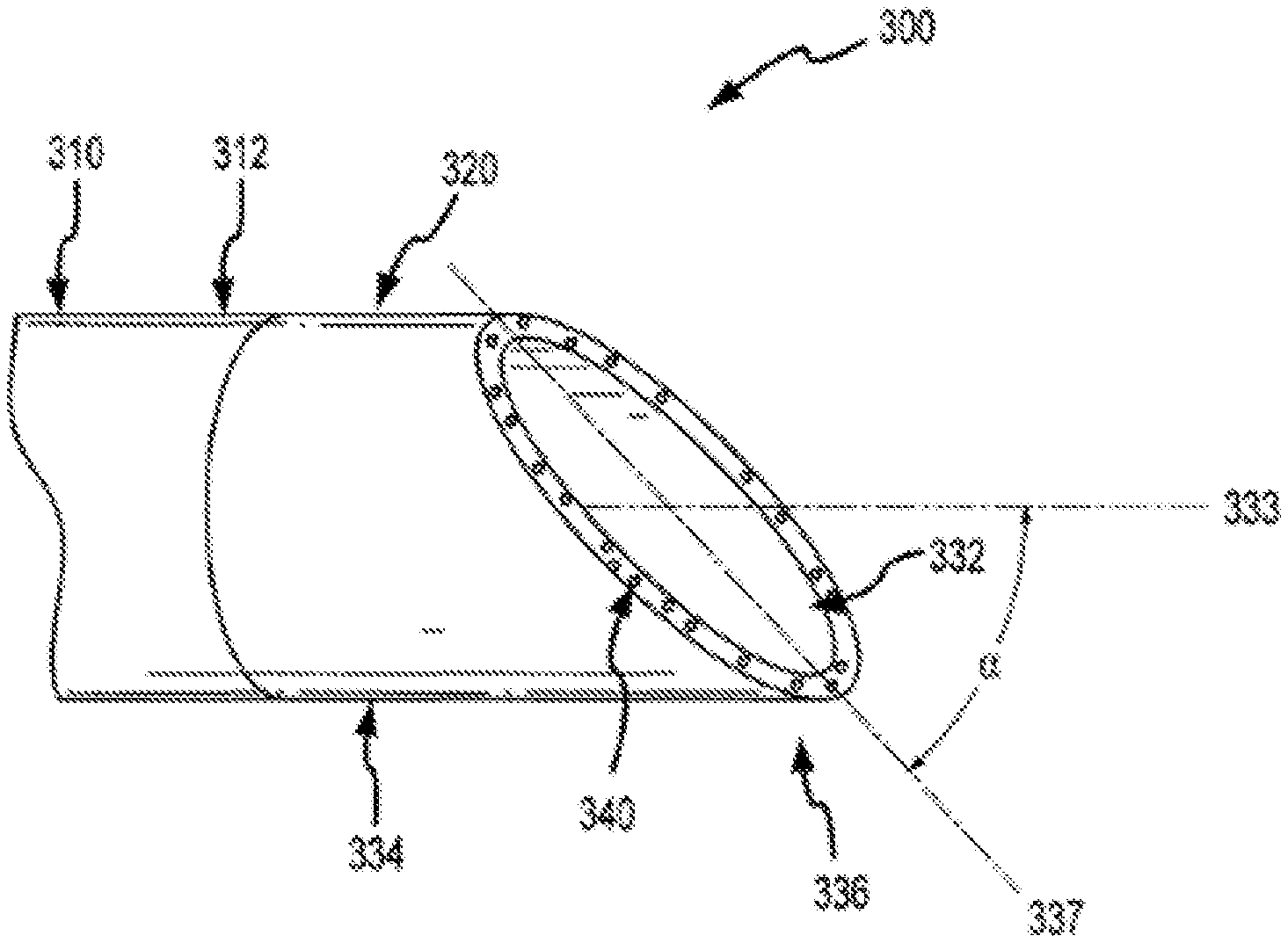
FIG. 3 illustrates a distal portion of a separating system according to embodiments of the present invention.
FIG. 4 illustrates a distal portion of a separating system according to embodiments of the present invention.
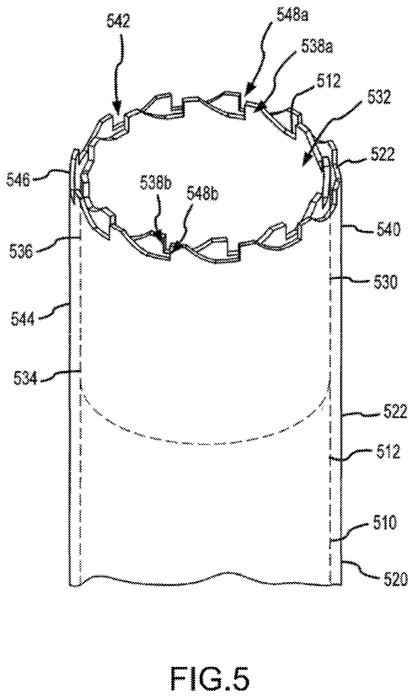
FIG. 5 illustrates a distal portion of a separating system according to embodiments of the present invention.
FIG. 6 depicts a distal portion of a separating system according to embodiments of the present invention.
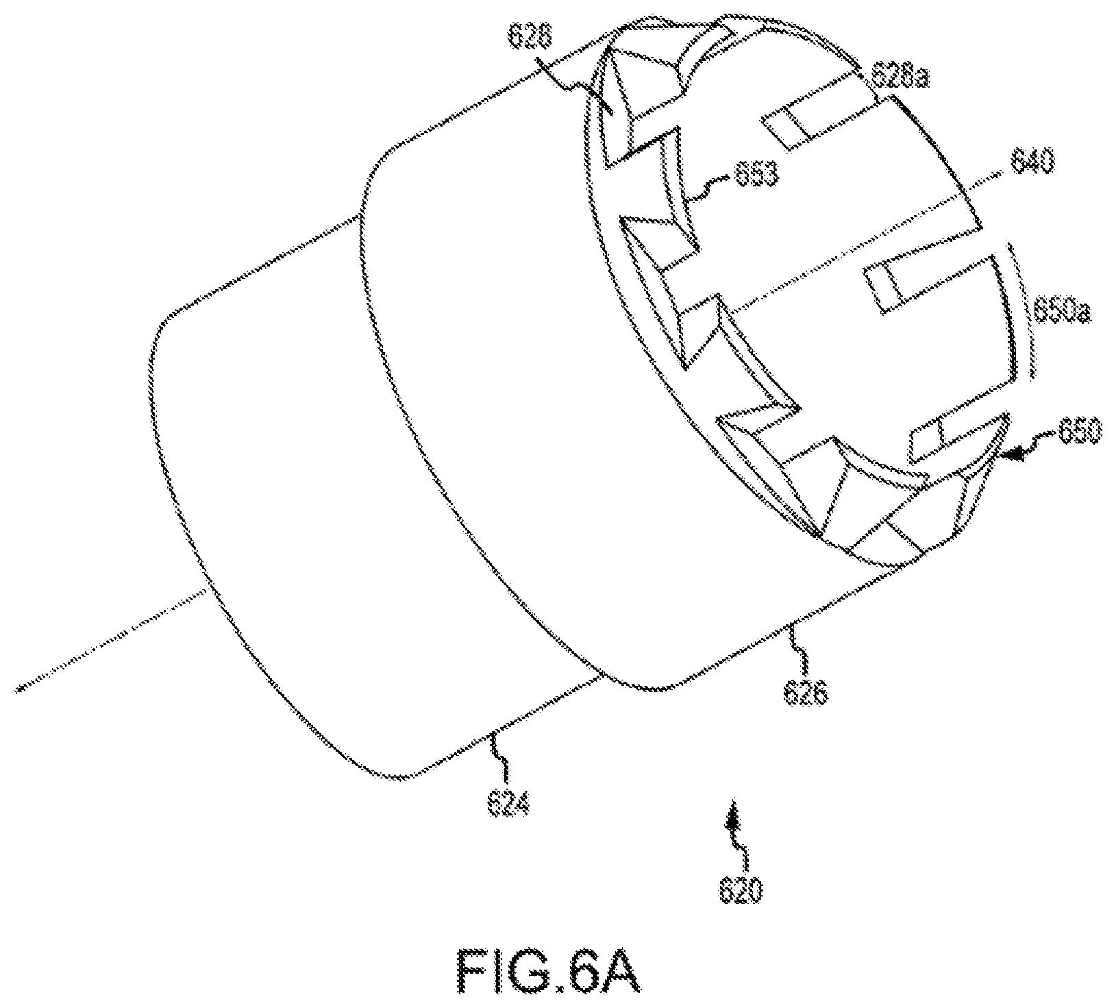
FIG. 6A depicts a distal portion of a separating system according to embodiments of the present invention.
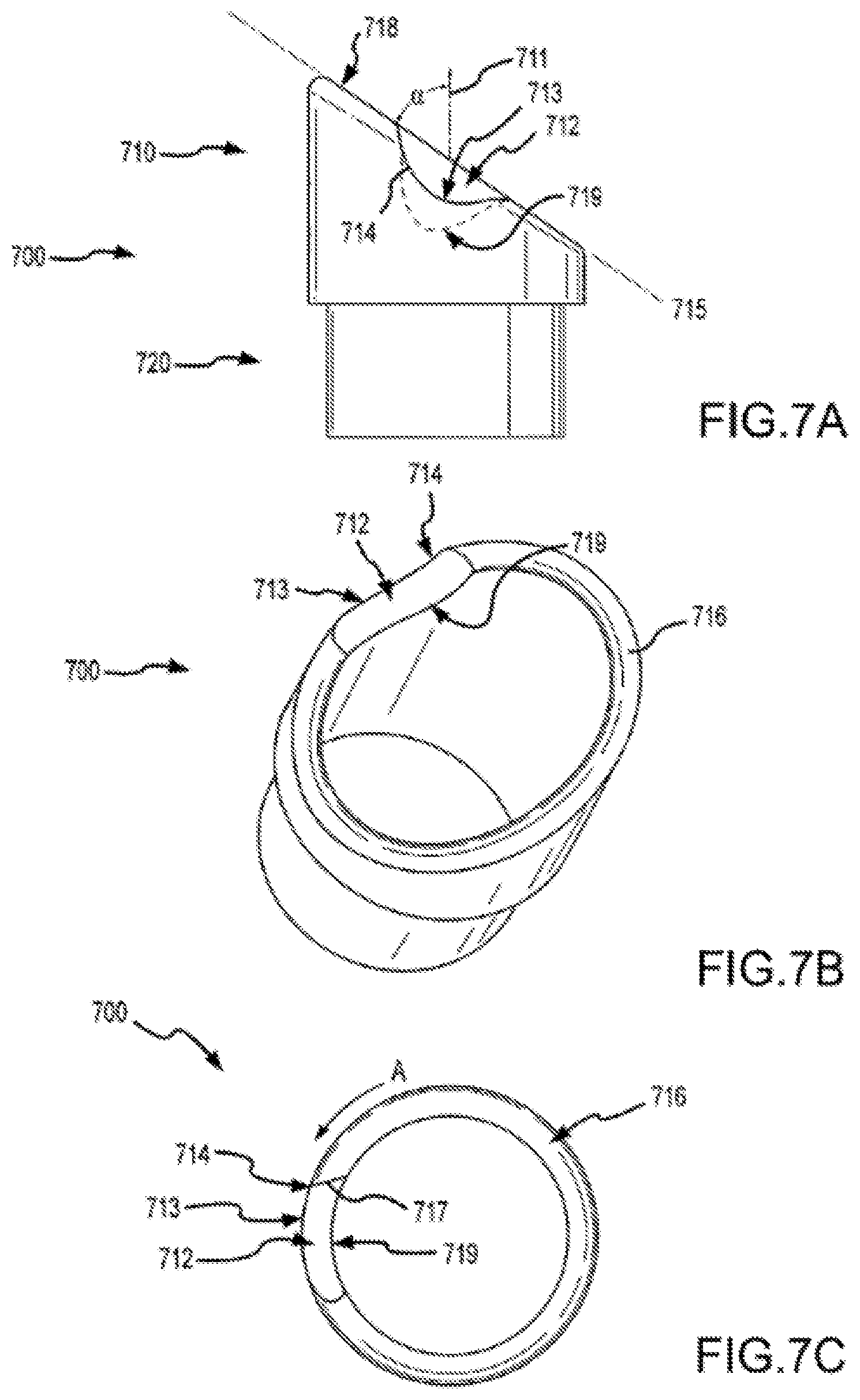
FIGS. 7A-7D show aspects of a separator according to embodiments of a present invention.
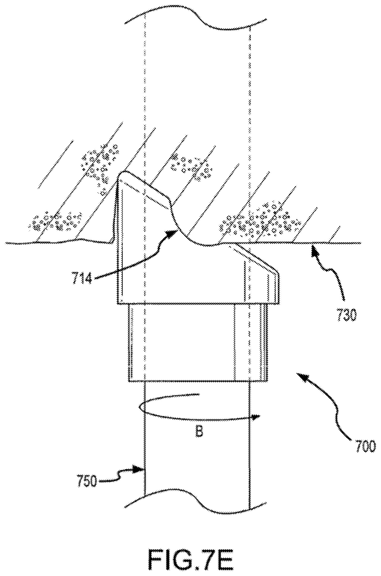
FIG. 7E shows a distal portion of a separating system in a method of use according to embodiments of the present invention.
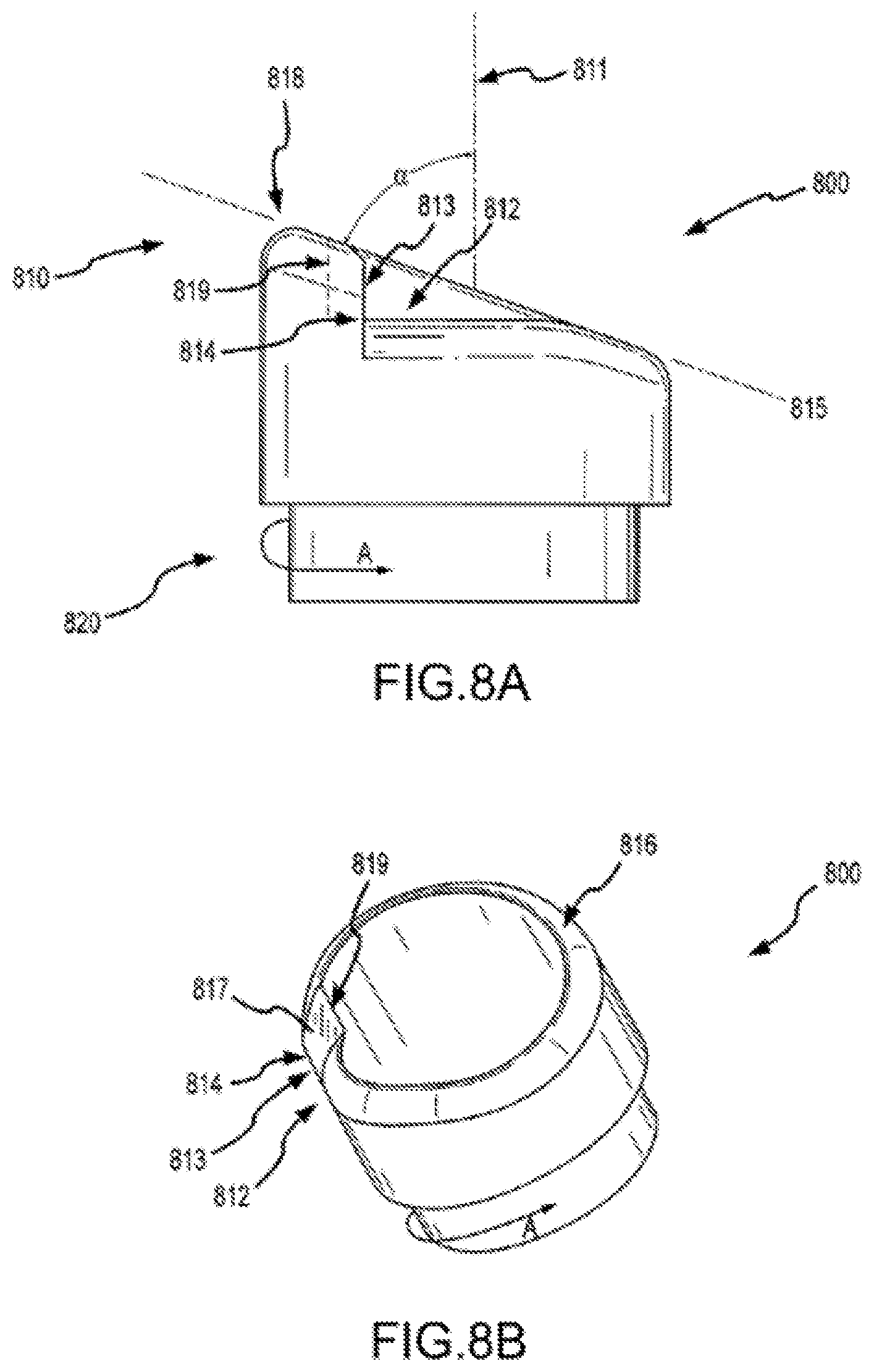
FIGS. 8A and 8B show aspects of a separator according to embodiments of a present invention.
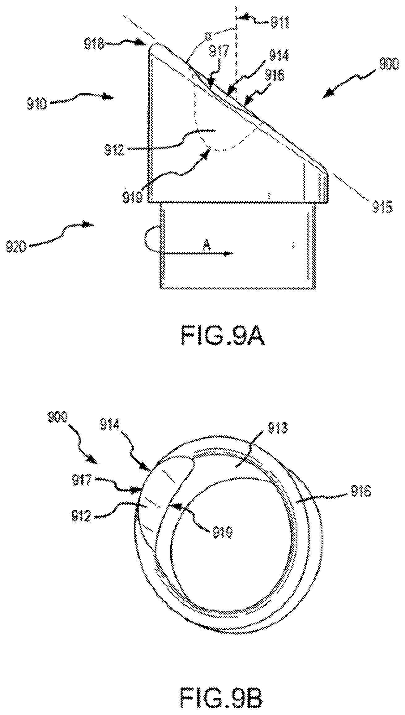
FIGS. 9A and 9B show aspects of a separator according to embodiments of a present invention.
FIGS. 10A and 10B show aspects of a separator according to embodiments of a present invention.
FIGS. 11A and 11B show aspects of a separator according to embodiments of a present invention.
FIG. 12 illustrates a cross section of a sheath according to embodiments of the present invention.
DETAILED DESCRIPTION OF THE INVENTION
Embodiments of the present invention provide a mechanical sheath and cutting tip that can be safely deployed within the vascular system of a patient. Such systems include a flexible and torqueable sheath and a hard separating mechanism. A separating system can include, for example, a flexible sheath coupled with a tip, which may include a separating surface or shape. The cutting or separating surface or shape can be contacted with patient tissue, and the sheath can be rotated to effect cutting or separating of the tissue. Although the sheath may be flexible, it can also be pushable in the sense that a force applied to the proximal end of the sheath is in large part transferred to the distal end of the sheath. The sheath may also exhibit a high resistance to kinking or crushing. For example, it is possible to force the sheath into a severe bend or tortuous path without causing permanent deformation or damage to the sheath. Moreover, the sheath maintains a desired amount of torqueability, in that the a rotational force applied to a proximal end of the sheath is effectively translated to a distal end of the sheath.
A separating system can be used as an intra-operative device to free or explant a chronically implanted pacing or defibrillator lead. The system can include an inner lumen designed to allow a pacing lead and lead locking device to pass through it, as the system slides over the lead toward the distal tip of the lead in the heart. Often the system includes an outer sheath or shaft that can be used during the extraction procedure as an introducer and to support and align an inner sheath or shaft. The outer sheath can also be used as a conduit to remove the inner shaft with the extracted lead or object, and can be used as a conduit to implant a new lead or object.
Turning now to the drawings, FIG. 1 shows a system 100 for separating an object from a patient tissue according to embodiments of the present invention. System 100 can have a length A' within a range from about 25 cm to about 75 cm. In some cases, length A' is about 50 cm. System 100 includes a sheath 110 having a proximal end 112 and a distal end 114. Sheath 110 may be, for example, a braided shaft. System 110 also includes a handle 120 coupled with the proximal end 112 of sheath 110. Handle 120 can have a length B' within a range from about 4 cm to about 15 cm. In some cases, length B' is about 10 cm. System 100 also includes a cutting member or separator 130 coupled with the distal end 114 or sheath 110. In some embodiments, sheath 110 may include or be coupled with a flared exit port 140 or a similar configuration that facilitates the introduction of leads through sheath 110. In some cases, a proximal end of sheath 110 may include or be coupled with a hemostasis valve or connection to inhibit or control bleeding at the sheath proximal end. Features such as flared exit port 140 or the hemostasis valve may also be incorporated into handle 120. In use, an operator may advance sheath 110 into a patient, and while sheath is disposed within the patient, remove pacing leads or other objects from the patient. The operator may also insert new or replacement pacing leads or other objects into the patient by placing them through flared exit port 140 and into sheath 110. Thus, flared exit port 140 and sheath 110 can facilitate the implantation of a pacing lead or other object. Optionally, system 100 may include a pull wire for deflecting the distal end of the sheath. In some embodiments, a pull wire may be housed within a separate lumen of the sheath, and attached with the tip or other proximally located feature. When an operator causes the pull wire to be retracted, the pull wire causes deflection of the tip or other proximally located feature. In many cases, it is desirable to deflect a sheath top or other proximally located feature away from the wall of a vein or other body lumen. In some embodiments, sheath 110 or a portion thereof may include a braid or braiding 111. A braid may include, for example, a woven metallic or fiber layer. Often, a braid includes a group of filaments that are interwoven in a specific form, such as a cylinder or a tubular structure. A braid can be applied to the interior of sheath 110, the exterior of sheath 110, or both. In some cases, a braid may be incorporated into or integral with a sheath material. In some embodiments, a braid feature confers additional robustness to a sheath or shaft. For example, a braid may prevent or inhibit a sheath from being kinked or crushed during use.
As shown in FIG. 1A, handle 120 can have an outer diameter C' within a range from about 0.25 to about 0.95 inches. In some cases, outer diameter C' is about 0.75 inches. As shown in FIG. 1B, sheath 110 can have an inner diameter D' within a range from about 0.090 to about 0.170 inch, and an outer diameter E within a range from about 0.140 to about 0.250 inch. In some cases, inner diameter D' is about 0.130 inch and outer diameter E is about 0.155 inch. Sheath 110 can have an inner surface 116 and an outer surface 118. In some cases, inner surface 116, outer surface 118, or both, are coated with or include a slippery, smooth, or lubricious material. Exemplary hydrophilic polymer coatings or materials that may be used are produced by Surmodics, Inc. of Eden Prairie, Minn. Thus, for example, when using system 100 to remove a pacing lead from a patient, outer surface 118 passes easily through the patient's anatomy, and inner surface 116 passes easily over the pacing lead, without creating unwanted or excessive friction.
FIG. 1C illustrates cylindrical cutting member 130 and distal end 114 of sheath 110. Cylindrical cutting member 130 can include an internal lumen 132, a proximal end 134, and a distal end 136. In some cases, distal end 136 of cutting member 130 defines a plane 137. As shown here, cutting member 130 has a central longitudinal axis 133, which can be defined by, for example, internal lumen 132 of the cutting member, inner surface 116 of the shaft, or the inner or outer surface of cutting member 130. An acute angle a between plane 137 and central longitudinal axis 133 can be within a range from about 30 degrees to about 85 degrees. In some cases, angle .alpha. is about 45 degrees. Distal end 136 of cutting member 130 can include a cutting edge or surface on part of the distal end 136. In some cases, distal end 136 includes a cutting edge or surface circumscribing the entire distal end of a bevel. A cutting edge or surface can include, for example, a blade or wedge for severing tissue or for separating tissue from an object or from adjacent tissue. In some cases, a cutting edge or surface includes an abrasive substance for abrading tissue or other material. Distal end 136 may include a metal or metal alloy such as titanium, stainless steel, or a metal or alloy coated with a hard coating such as titanium oxide. Advantageously, the use of a flexible and torqueable sheath as described elsewhere herein allows an operator to advance a hard distal end 136 along an entire or substantial portion of a pacing lead, or object to be removed or separated from a patient's body, which may be located in a tortuous or labyrinthine vessel or lumen.
Sheath 110 may be motorized to rotate or coupled with a motor that induces rotation in or applies torque to the sheath. In some embodiments, sheath 110 may be motorized to move in a reciprocating motion back and forth like a clothes washer cylinder or drum. Sheath 110 can be constructed to have varying degrees of stiffness along the length of the sheath. In some cases, a distal portion or end is more flexible relative to a proximal portion or end of the sheath. For example, distal end 114 of sheath 110 may include a flexible portion approximately 5 to 15 cm in length. In some cases, sheath 110 or sections or portions thereof may be fabricated via multi-durometer construction or multi-diameter construction techniques. For example, a sheath may include a series of one or more tubes or tube-like elements of progressively reduced durometer material fused together to form a sheath of varying stiffness. Accordingly, a sheath may have one portion that exhibits a first stiffness, and a second portion that exhibits a second stiffness. In one embodiment, the hardness of the tubes or tube-like structures become progressively softer or more flexible when going from the proximal end of the sheath to the distal end of the sheath. In some embodiments, tubes or tube-like structures may have progressively smaller diameters or thicknesses when going from the proximal end of the sheath to the distal end of the sheath. Relatedly, sheath 110 can present any of a variety of braid angles. For example, a sheath or components thereof may have sections, portions, or layers having a higher angle braid angle that imparts more flexibility. Similarly, a sheath or components thereof may have sections, portions, or layers having a lower braid angle that imparts less flexibility. Sheath 110 can be configured to provide a desired torque response. For example, in some embodiments sheath 110 provides close to 1:1 torque response. Torque response can refer to the ratio of proximal rotations to distal rotations. In some embodiments, a sheath can have a torque response within a range from about 1:0.6 to about 1:1. In similar embodiments, a sheath can have a torque response within a range from about 1:0.7 to about 1:1. A sheath may also have a torque response within a range from about 1:0.8 to about 1:1. In some cases, a sheath has a torque response within a range from about 1:0.9 to about 1:1. Sheath embodiments of the present invention can advantageously provide an optimum or high torque response while retaining a high degree of flexibility, which combination is often not available with current sheath or lead removal products.
System 100 may also include a positive fixation assembly 150 or configuration for handle 120. In this way, handle 120 can be fixed or is fixable at any desired location along the length of sheath 110. In use, when sheath 110 is inserted into a patient, an operator can therefore adjust the position of handle 120 along the length of sheath 110. For example, the operator may fix handle 120 at a location that is close to the patient or near a sheath insertion point. In this way, the operator can reduce or otherwise modulate or select the amount of sheath that is present between the handle and the patient's body or insertion point. The ability to control the position of handle 120 along the length of sheath 110 allows the operator to have more easily maneuver the system 110. If the distance between handle 120 and the patient's body or insertion point is too great, for example, the system may exhibit undesirable flexing or movement as the operator maneuvers the system. The positive fixation feature allows the handle to be movable to more proximal positions along the sheath as a lead extraction progresses.
FIG. 2A shows a system 200 for separating an object from a patient tissue according to embodiments of the present invention. System 200 includes a sheath 210 having a proximal end 212 and a distal end 214. Sheath 210 may be include from, for example, a braided shaft. System 210 also includes a handle 220 coupled with the proximal end 212 of sheath 210. System 200 also includes a cutting member or separator 230 coupled with the distal end 214 or sheath 210, and an outer sheath 240 encompassing at least a portion of sheath 210. Outer sheath 240 can have a length A' within a range from about 25 cm to about 50 cm. In some cases, length A' is about 40 cm. As shown in FIG. 2B, outer sheath 240 can have an inner diameter B' within a range from about 0.130 inch to about 0.220 inch. In some cases, inner diameter B' is about 0.170 inch. Often the outer sheath or shaft can be used during an extraction procedure as an introducer and to support and align the inner sheath or shaft. The outer sheath can also be used as a conduit to remove the inner shaft with the extracted lead or object, and can be used as a conduit to implant a new lead or object. In some embodiments, an outer sheath is left in place during a lead extraction procedure once the inner sheath and lead are removed from the patient. The outer sheath can be used as a conduit for a guidewire to facilitate the implantation of a new lead. The outer sheath distal tip can be disposed into the atrium, or retracted into the brachiocephalic vein. In some embodiments, an inner sheath and an outer sheath are advanced over a lead in an alternating "inchworm" technique. An operator may determine that a tissue obstruction is met if the inner sheath will not advance into the vessel or vein, if the inner sheath bows outward slightly when longitudinal pressure is applied, if fluoroscopy indicates that the inner sheath distal end does not advance relative to the lead body, or if fluoroscopy indicates that the inner sheath distal end is not caught on a lead electrode, a lead bend, or another lead. If an obstruction such as scar tissue is met and the inner sheath cannot be advanced, the operator may consult orthogonal fluoroscopic views to ensure that the distal tip of the inner sheath is aligned with the longitudinal axis of the lead. The operator may retract the outer sheath so that its distal end does not overlap the distal tip of the inner sheath. The operator can press the inner sheath into or against the obstruction and rotate the sheath to separate the tissue or obstruction from the lead. The outer sheath can then be advanced to a new position along the inner sheath. In some embodiments, when the lead or object is free, it is drawn into the inner sheath before the lead, the inner sheath, and the outer sheath are removed from the body. Separating systems according to the present invention are also well suited for use with lead locking devices. In some embodiments containing an inner sheath and an outer sheath, the sheaths can each have distal tips configured for a scissoring cutting action as described herein with reference to FIG. 5. In some embodiments, system 200 includes a single sheath.
FIG. 3 shows a portion of a separating system according to embodiments of the present invention. System 300 includes a shaft or sheath 310 having a distal end 312. System 300 also includes a cutting member or separator 320 coupled with distal end 312. Cutting member includes an internal lumen 332, a proximal end 334, and a distal end 336. System 300 can also include an abrasive material 340 or a separating mechanism or means disposed on or encrusted in distal end 336 of cutting member 320. In some embodiments, abrasive material 340 includes diamond chips, aluminum carbide chips, silica carbide chips, and the like. Abrasive material can be attached with distal end 336 via any of a variety of methods, including gluing, vapor deposition, embedding, and the like. In some cases, distal end or rim 336 of cutting member 320 defines a plane 337, and internal lumen 332 of the cutting member 320 defines a central longitudinal axis 333. An acute angle .alpha. between plane 337 and central longitudinal axis 333 can be about 45 degrees. In some cases, angle .alpha. is within a range from about 30 degrees to about 85 degrees. System 300 can be configured such that when distal end 336 is pressed onto patient tissue, abrasive material 340 does not cut or sever the tissue, but when distal end is pressed onto patient tissue and sheath 310 or cutting member 320 is rotated about central longitudinal axis 333, abrasive material 340 acts to cut or sever the tissue.
FIG. 4 shows a portion of a separating system according to embodiments of the present invention. System 400 includes a sheath 410 having a distal end 412. System 400 also includes a cutting member or separator 420 coupled with distal end 412. Cutting member includes an internal lumen 422, a proximal end 424, and a distal end or rim 426. Internal lumen 422 defines a central longitudinal axis 423. Distal end 426 of cutting member 420 includes a separating means or mechanism such as a cutting edge 426a aligned with central longitudinal axis 423, and cutting edge or blade 426a has a proximal end 426b and a distal end 426c. Distal end 426 of cutting member 420 also includes a distal edge 426d having a proximal end 426e that joins or meets with the cutting edge proximal end 426b, and a distal end 426f that joins or meets with cutting edge distal end 426c. Separating mechanism 426a can present any desired profile for separating tissue. As shown here, separating mechanism 426a defines a substantially straight edge profile that extends between cutting edge distal end 426c and cutting edge proximal end 426b. In some embodiments, the profile provided by separating mechanism 426a between cutting edge distal end 426c and cutting edge proximal end 426b presents an arc, or a convex or concave contour. In some cases, the profile may have an irregular contour. In addition, leading edge 426c can have a rounded profile to prevent tissue penetration when the sheath is advanced longitudinally. Relatedly, separating mechanism 426a may also provide a beveled edge, similar to blade 814 as described with reference to FIG. SB. Distal edge 426d often presents or includes a spiral or helical contoured portion or shape. Any of a variety of materials can be used in the manufacture of a cutting element. For example, a cutting element may include a metal or metal alloy such as titanium, stainless steel, or a metal coated with a hard coating such as titanium oxide. In some embodiments, cutting member 420 is configured to cut only when rotated one direction, when blade 426a presents a leading edge, as indicated by arrow A.
FIG. 5 shows a portion of a separating system according to embodiments of the present invention. System 500 includes an internal sheath 510 having a distal end 512, and an external sheath 520 having a distal end 522. System 500 also includes an internal cutting member or separator 530 coupled with distal end 512. Internal cutting member 530 includes an internal lumen 532, a proximal end 534, and a distal end or rim 536. In some cases, internal cutting member is cylindrical in shape. Distal end 536 of internal cutting member 530 can include one or more cutting blades 538a,b. System 500 also includes an external cutting member or separator 540 coupled with distal end 522. External cutting member 540 includes an internal lumen 542, a proximal end 544, and a distal end 546. In some cases, external cutting member is cylindrical in shape. Distal end 546 of external cutting member 540 can include one or more cutting blades or separating means or mechanism 548a,b. As shown here, internal cutting member 530 is disposed at least partially within external cutting member 540, and internal and external cutting members 530, 540 are configured for relative rotational movement so that blade pairs can form scissors or clippers. For example, blade 538a and blade 548a can be brought together or toward each other in a shearing or clipping fashion. In some embodiments, each of the internal and external sheaths have distal metal bands. Each band can be serrated in such a way that each band forms one or more blades of one or more scissor pairs, where one blade of each scissor pair is located on each band. In use, the internal and external sheaths can be rotated relative to one another to close the scissor pairs and produce a cutting action. In addition to or instead of the cutting action, rotation or advancement of one or both of the sheaths can operate to perform a dilating or stripping action. In many cases, however, the actuation of the distal end of the system provides a primarily cutting or clipping action.
FIG. 6 shows a system 600 for cutting tissue in a patient according to embodiments of the present invention. System 600 includes a sheath 610 having a distal end 612, and a cutting member 620 coupled with distal end 612. In some cases, cutting member 620 provides a cylindrical shape. Cutting member 620 includes an internal lumen 622, a proximal end 624, and a distal end or rim 626. In some cases, distal end 626 of cutting member 620 defines a plane 630, and internal lumen 622 of the cutting member 620 defines a central longitudinal axis 640, wherein an acute angle .alpha. between plane 630 and central longitudinal axis 640 is within a range from about 45 degrees to about 90 degrees. In some cases, angle .alpha. is within a range from about 60 degrees to about 85 degrees. In embodiments where there is such an angle, distal end 626 of cutting member 620 may present a leading edge 660 and a trailing edge 650. For example, leading edge 660 can be disposed toward the cutting member distal end 626 and trailing edge 670 can be disposed toward the cutting member proximal end 624. In some cases, distal end 626 of cutting member 620 includes a plurality of teeth or serrations 650. Teeth 650 can have cutting edges or blades 652 along the side walls of the teeth. The top surface or peripheral lateral surfaces 651 of the teeth can be rounded or smooth. The inner diameter 653 of each tooth may present a sharp edge. In some cases, cutting edges 652 are in perpendicular alignment with plane 630 or with a plane defined by face 628. In some cases, cutting edges 652 are in directional alignment with a central longitudinal axis defined by the cutting member or separator. In some cases, cutting or separating edges 652 are in directional alignment with a central longitudinal axis defined by the sheath. As shown in FIG. 6A, distal end 626 of cutting member 620 may present a circular face 628, and a plurality of teeth or crests 650 are disposed circumferentially around the face. There is a substantially equivalent or equivalent arc spacing 628a between each tooth 650, and each tooth presents a similar or equivalent width arc width 650a along inner diameter edge 653. In some embodiments, the arc spacing 628a between teeth 650 may be unequal. In some embodiments, the arc width 650a may vary among different teeth 650. In some cases, teeth may be present at one portion of the face 628, and absent from another portion of the face 628. For example, in some embodiments, leading edge 660 may include one or more teeth, whereas trailing edge 670 may contain no teeth. Relatedly, in some embodiments one portion of the face may contain more teeth than another similar-sized portion of the face.
FIGS. 7A-7D illustrate a cutting member or separator 700 according to embodiments of the present invention. As shown in the side view provided by FIG. 7A, cutting member 700 includes a distal end or rim 710 and a proximal end 720. Distal end 710 is beveled and defines a plane 715. In some embodiments, plane 715 may be skew or not perpendicular to central longitudinal axis 711. For example, there may be an acute angle .alpha. between plane 715 and axis 711 within a range from about 30 degrees to about 85 degrees. Axis 711 can be a central longitudinal axis defined by an internal lumen of cutting member 700. Distal end 710 also includes a recess 712 having a blade or separating mechanism 714. As shown in the perspective view provided by FIG. 7B, distal end 710 also includes a rounded or smooth surface 716. Distal end 710 can also include a distal tip 718 that is rounded or smooth. Often, distal tip 718 is somewhat blunted, and does not present a sharp point or a leading cutting edge when cutting member 700 is advanced. In use, distal tip 718 of cutting member 700 can be pressed lightly against a patient tissue without severing the tissue. Cutting member 700 can be rotated in the direction indicated by the arrow A shown in FIG. 7C to advance the leading edge of blade 714. In contrast to rounded or smooth surface 716, recess 712 can present a scooped or beveled surface that presents a sharp, acute, or knifelike blade 714. Outer diameter 713 of recess 712 can be disposed proximal relative to inner diameter 719 of recess 712. Blade 714 can be disposed along the outer diameter 713 of recess 712. As shown in FIG. 7D, blade 714 may also be disposed along inner diameter 719, or between outer diameter 713 and inner diameter 719, and may define any suitable combination of convex, concave, or curved bevel surface 717. FIG. 7E provides a side view of cutting member 700 in use, where cutting member 700 is rotated in the direction indicated by arrow B, so that blade 714 presses against and cuts patient tissue 730. In this manner, tissue 730 can be severed or separated from an object such as a pacing lead 750.
FIGS. 8A and 8B illustrate a cutting member or separator 800 according to embodiments of the present invention. As shown in the side view provided by FIG. 8A, cutting member 800 includes a distal end or rim 810 and a proximal end 820. Distal end 810 is beveled and defines a plane 815. In some embodiments, plane 815 may be skew or not perpendicular to central longitudinal axis 811. For example, there may be an acute angle .alpha. between plane 815 and axis 811 within a range from about 30 degrees to about 85 degrees. Axis 811 can be a central longitudinal axis defined by an internal lumen of cutting member 800. Distal end 810 also includes a notch 812 and a blade or separating means or mechanism 814. As shown in the perspective view provided by FIG. 8B, distal end 810 also includes a rounded or smooth surface 816. Often, distal tip 818 is somewhat blunted, and does not present a sharp point or a leading cutting edge when cutting member 800 is advanced. In use, a distal tip 818 of cutting member 800 can be pressed lightly against a patient tissue without severing the tissue. In a manner similar to that described with reference to cutting member 700, cutting member 800 can be rotated so as to cut patient tissue. Cutting member 800 can be rotated in the direction indicated by the arrow A shown in FIG. 8B to advance the leading edge of blade 814. In some embodiments, cutting member 800 is configured to cut only when rotated one direction, when blade 814 presents a leading edge. In contrast to rounded or smooth surface 816, notch 812 can present a scooped or beveled surface that presents a sharp, acute, or knifelike blade 814. Outer diameter 813 of notch 812 can be disposed proximal relative to inner diameter 819 of recess 812. Blade 814 can be disposed along the outer diameter 813 of notch 812. In a manner similar to that described above with reference to blade 714, blade 814 may also be disposed along inner diameter 819, or between outer diameter 813 and inner diameter 819, and may define any suitable combination of convex, concave, or curved bevel surface 817.
FIGS. 9A and 9B show a cutting member or separator 900 according to further embodiments of the present invention. As shown in the side view provided by FIG. 9A, cutting member 900 includes a distal end or rim 910 and a proximal end 920. Distal end 910 is beveled and defines a plane 915. In some embodiments, plane 915 may be skew or not perpendicular to central longitudinal axis 911. For example, there may be an acute angle .alpha. between plane 915 and axis 911 within a range from about 30 degrees to about 85 degrees. Axis 911 can be a central longitudinal axis defined by an internal lumen of cutting member 900. As shown in the perspective view provided by FIG. 9B, distal end 910 also includes a rounded or smooth surface 916, and a depression 912 in an interior surface 913 of cutting member 900. Depression 912 presents a blade or separating means or mechanism 914 for use in cutting or separating patient tissue. In use, a distal tip 918 of cutting member 900 can be pressed lightly against a patient tissue without severing the tissue. In a manner similar to that described with reference to cutting member 700, cutting member 900 can be rotated so as to cut patient tissue. Cutting member 900 can be rotated in the direction indicated by the arrow A shown in FIG. 9A to advance the leading edge of blade 914. In contrast to rounded or smooth surface 916, depression 912 can present a scooped or beveled surface that presents a sharp, acute, or knifelike blade 914. Outer diameter 917 of depression 912 can be disposed proximal relative to inner diameter 919 of depression 912. Blade 914 can be disposed along the outer diameter 913 of depression 912, or blade 914 may be at least partially disposed between outer diameter 913 and inner diameter 919. In a manner similar to that described above with reference to blade 714, blade 914 may also be disposed along inner diameter 919.
FIGS. 10A and 10B show a cutting member or separator 1000 according to embodiments of the present invention. As shown in the side view provided by FIG. 10A, cutting member 1000 includes a distal end or rim 1010 and a proximal end 1020. Distal end 1010 is beveled and defines a plane 1015. In some embodiments, plane 1015 may be skew or not perpendicular to central longitudinal axis 1011. For example, there may be an acute angle .alpha. between plane 1015 and axis 1011 within a range from about 30 degrees to about 85 degrees. Axis 1011 can be a central longitudinal axis defined by an internal lumen of cutting member 1000. As shown in the perspective view provided by FIG. 10B, distal end 1010 also includes rounded or smooth surface 1016, and a blade or sharp surface 1014 that extends at least partially around the periphery of distal end 1010, where blade or separating mechanism or means 1014 can be used for cutting or separating patient tissue. Often, blade 1014 is disposed at or near an inner surface 1013 of cutting member 1000. In some cases, blade 1014 can include an edge of inner surface 1013. In use, a distal tip 1018 of cutting member 1000 can be pressed lightly against a patient tissue without severing the tissue. In a manner similar to that described with reference to cutting member 700, cutting member 1000 can be rotated so as to cut patient tissue. Cutting member 1000 can be rotated in the direction indicated by the arrow A shown in FIG. 10A, or in the direction indicated by arrow B, to advance the leading edge of blade 1014. As shown here, rounded or smooth surface 1016 may be continuous with a sharp, acute, or knifelike blade 1014. Surface 1016 may be disposed at or toward outer diameter 917 of cutting member 1000, and blade 1014 may be disposed at or toward inner diameter 1019 of cutting member 1000. In some cases, blade 1014 may be disposed distal to smooth surface 1016, and in some cases blade 1014 may be disposed proximal to smooth surface 1016. In some embodiments, cutting or separating mechanism 1014 can be disposed along the inner diameter 1019 of separator 1000. Thus, in use the cutting or separating mechanism 1014 can be kept away from a vessel wall or other portion of the patient's body. Separating mechanism 1014 can also extend circumferentially about the distal end of separator 1000, and thus can provide a cutting or separating action when separator 1000 is advanced longitudinally, as well as when separator 1000 is rotated in either direction.
FIGS. 11A and 11B show a cutting member or separator 1100 according to embodiments of the present invention. As shown in the side view provided by FIG. 11A, cutting member 1100 includes a distal end or rim 1110 and a proximal end 1120. Distal end 1110 defines a plane 1115 that is substantially perpendicular or perpendicular to a central longitudinal axis 1111 of cutting member 1100, and thus angle .alpha. is 90 degrees or about 90 degrees. In some embodiments, plane 1115 may be skew or not perpendicular to central longitudinal axis 1111. For example, there may be an acute angle between plane 1115 and axis 1111 within a range from about 30 degrees to about 85 degrees. As shown in the perspective view provided by FIG. 11B, distal end 1110 also includes at least one rounded or smooth surface 1116, and at least one recess 1112, where recess 1112 can provide a blade or separating mechanism or means 1114. In use, a distal tip 1118 of cutting member 1100 can be pressed lightly against a patient tissue without severing the tissue. In a manner similar to that described with reference to cutting member 700, cutting member 1100 can be rotated so as to cut patient tissue. Cutting member 1100 can be rotated in the direction indicated by the arrow A shown in FIG. 11B to advance the leading edge of blade 1114. In contrast to rounded or smooth surface 1016, recess 1112 can present a scooped or beveled surface that presents a sharp, acute, or knifelike blade 1114. Outer diameter 1117 of recess 1112 can be disposed proximal relative to inner diameter 1119 of recess 1112. Blade 1114 can be disposed along the outer diameter 1117 of recess 1112. In a manner similar to that described above with reference to blade 714, blade 1114 may also be disposed along inner diameter 1119, or between inner diameter 1119 and outer diameter 1117.
FIG. 12 illustrates a cross section of a flexible sheath or shaft according to embodiments of the present invention. Shaft 1200 includes an inner lumen 1210, an inner layer 1220, a central layer 1230, a braid layer 1240, and an outer layer 1250. In some embodiments, an inner diameter ID of shaft 1200 is within a range from about 0.147 inch to about 0.187 inch. Optionally, inner diameter ID can be about 0.167 inch. In some embodiments, an outer diameter OD of shaft 1200 is within a range from about 0.175 inch to about 0.215 inch. Optionally, outer diameter OD can be about 0.195 inch. Shaft 1200 may have a total wall thickness WT within a range from about 0.011 inch to about 0.068 inch. Inner layer 1220 may include a fluoropolymer such as fluorinated ethylene propylene (FEP) or polytetrafluoroethylene (PTFE). Inner layer 1220 can have a wall thickness of about 0.002 inch. Central layer 1230 may include a thermoplastic elastomer such as Pebax (polyether bloc amide), with a durometer of about 25. Central layer 1230 can have a wall thickness of about 0.002 inch. Braid layer 1240 can include a 304 stainless steel ribbon having a thickness of about 0.001 inch and a width of about 0.004 inch. Braillayer 1240 can have a wall thickness of about 0.002 inch, due to two overlapping layers of the 0.001 inch thick ribbon. Outer layer 1250 can include a thermoplastic elastomer such as Pebax.RTM. with a durometer of about 69. In some embodiments, the braid is a 16 strand braid having a 35 Pic count (crossings per inch). The braid may present 28 percent coverage (surface area) and a braid angle of about 67.8 degrees. Such sheath configurations provide for a very flexible construction that retains effective torque properties.
In some embodiments, shaft 1200, in combination with a separator, can be dimensioned to remove pacing leads up to 13 French (0.170 inch) in diameter. The shaft can have a bending stiffness of less than about 6 pounds per inch (lb/in), and a torsional stiffness greater than about 0.177 pound inch (lb-in). The separator can include a separating mechanism having a hardness greater than about B65 Rockwell. The separating mechanism hardness can be measured by the Rockwell scale, a standard scale used to grade metals. Table 1 provides a comparison between an exemplary shaft embodiment and other commonly used lead extraction shafts.
TABLE-US-00001 TABLE 1 Bending Torsional Transmission Test Stiffness (lb-in) Number (lbf/in) 90.degree. 180.degree. Shaft 1 3.674 0.266 0.434 0.195 inch OD 2 3.681 0.169 inch ID 3 3.81 Commercial sheath 1 1 13.643 0.637 0.708 0.18 inch OD 2 15.19 0.151 inch ID 3 14.626 Commercial sheath 2 1 6.662 0.531 0.903 0.205 inch OD 2 7.071 0.169 inch ID 3 7.006 Commercial sheath 3 1 6.965 0.363 0.531 0.136 inch OD 2 6.998 0.109 inch ID 3 6.729 Commercial sheath 4 1 3.31 0.150 0.186 0.153 inch OD 2 3.292 0.112 inch ID 3 3.284 Commercial sheath 5 1 13.009 0.205 inch OD 2 13.457 0.168 inch ID 3 13.932 Commercial sheath 6 1 2.983 0.153 inch OD 2 3.014 0.112 inch ID 3 3.012
Table 1 indicates that embodiments of the present invention provide a sheath having bending properties similar to a smaller commonly available sheath. However, the present sheath can be sized to accommodate a lead or other object having a large diameter, while still retaining desirable torque properties. Moreover, embodiments of the present invention provide a system that includes a flexible and torqueable sheath and a hard separating mechanism.
Bending stiffness can be defined as the slope of the force/deflection curve pursuant to a flexural test such as ASTM D790 (e.g. 3 point bend test with 3 inch span length). Embodiments of the present invention provide sheaths having a bending stiffness of less than about 6 pound force per inch. Torsional transmission can be defined as the resulting torque load (e.g. in Newton-centimeters) transmitted to a distal end of a sheath while rotating a proximal end of the sheath a given amount (e.g. 90 degrees). The torsional transmission values provided in Table 1 correspond to a span (tube) length of 12 inches. An exemplary separating system may therefore include a flexible shaft having an inner diameter greater than about 0.130 inch and a bending stiffness of less than about 6 lb/in. The shaft can have a torsional transmission of greater than about 0.177 lb-in. The system can also include a separating mechanism having a hardness greater than about B65 Rockwell.
In addition to being well suited for the removal or detachment of pacing leads from a patient, embodiments of the present invention are well suited for detaching or removing any of a variety of objects from a patient, such as catheters, wires, implants, or other foreign bodies. Such objects may be disposed in veins, arteries, or any body lumen, cavity, or tissue.
Embodiments of the invention have now been described in detail. However, it will be appreciated that the invention may be carried out in ways other than those illustrated in the aforesaid discussion, and that certain changes and modifications may be practiced within the scope of the appended claims. Accordingly, the scope of this invention is not intended to be limited by those specific examples, but rather is to be accorded the scope represented in the following claims.
* * * * *
D00000
D00001
D00002
D00003
D00004
D00005
D00006
D00007
D00008
D00009
D00010
D00011
D00012

D00013
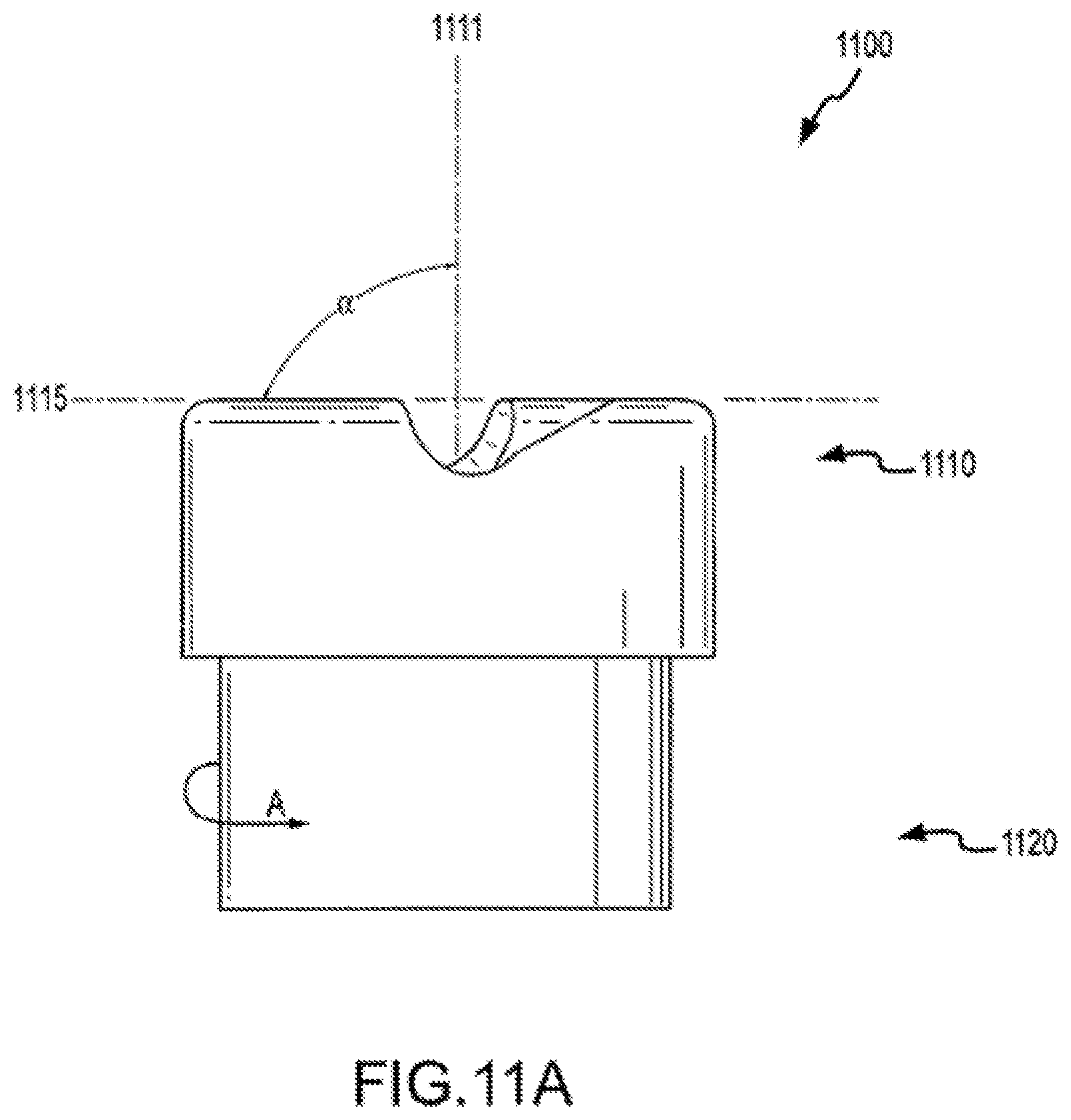
D00014
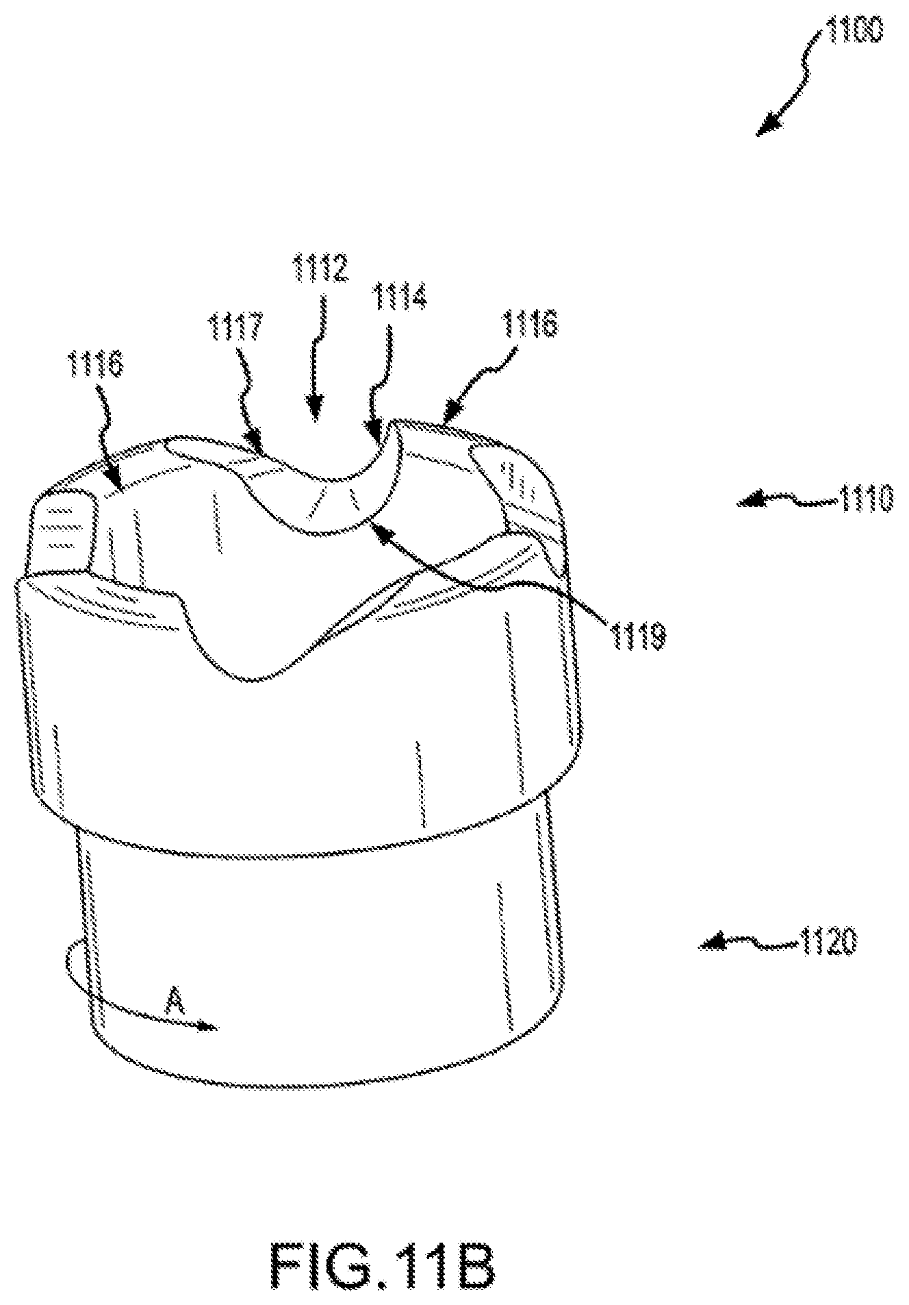
D00015
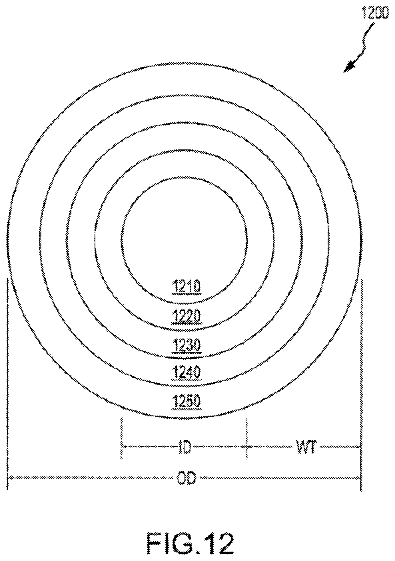
XML
uspto.report is an independent third-party trademark research tool that is not affiliated, endorsed, or sponsored by the United States Patent and Trademark Office (USPTO) or any other governmental organization. The information provided by uspto.report is based on publicly available data at the time of writing and is intended for informational purposes only.
While we strive to provide accurate and up-to-date information, we do not guarantee the accuracy, completeness, reliability, or suitability of the information displayed on this site. The use of this site is at your own risk. Any reliance you place on such information is therefore strictly at your own risk.
All official trademark data, including owner information, should be verified by visiting the official USPTO website at www.uspto.gov. This site is not intended to replace professional legal advice and should not be used as a substitute for consulting with a legal professional who is knowledgeable about trademark law.