Percussion tool
Krug , et al. October 27, 2
U.S. patent number 10,814,468 [Application Number 16/164,000] was granted by the patent office on 2020-10-27 for percussion tool. This patent grant is currently assigned to Milwaukee Electric Tool Corporation. The grantee listed for this patent is MILWAUKEE ELECTRIC TOOL CORPORATION. Invention is credited to Kevin Gee, Zbyn{hacek over (e)}k Kadlec, Gunter Karg, Alexander Krug, Andrew Delmar Van Hoorn.


| United States Patent | 10,814,468 |
| Krug , et al. | October 27, 2020 |
Percussion tool
Abstract
A percussion tool is used for performing a chiseling operation on a workpiece with a chisel. The percussion tool comprises a housing including a cylinder portion, a tool holder coupled to the cylinder portion for holding the chisel, and a percussion mechanism including a striker supported for reciprocation in the cylinder portion. The percussion mechanism is configured to impart repeated axial impacts to the chisel with the striker. The percussion tool further comprises a flange between the cylinder portion and the tool holder. Movement of the chisel within the tool holder toward the percussion mechanism is stopped by the flange.
| Inventors: | Krug; Alexander (Leutenbach, DE), Kadlec; Zbyn{hacek over (e)}k (P{hacek over (r)}e{hacek over (s)}tice, CZ), Karg; Gunter (Winnenden, DE), Van Hoorn; Andrew Delmar (Menomonee Falls, WI), Gee; Kevin (Milwaukee, WI) | ||||||||||
|---|---|---|---|---|---|---|---|---|---|---|---|
| Applicant: |
|
||||||||||
| Assignee: | Milwaukee Electric Tool
Corporation (Brookfield, WI) |
||||||||||
| Family ID: | 1000005140320 | ||||||||||
| Appl. No.: | 16/164,000 | ||||||||||
| Filed: | October 18, 2018 |
Prior Publication Data
| Document Identifier | Publication Date | |
|---|---|---|
| US 20190118364 A1 | Apr 25, 2019 | |
Related U.S. Patent Documents
| Application Number | Filing Date | Patent Number | Issue Date | ||
|---|---|---|---|---|---|
| 62650745 | Mar 30, 2018 | ||||
| 62574838 | Oct 20, 2017 | ||||
| Current U.S. Class: | 1/1 |
| Current CPC Class: | B25D 11/04 (20130101); B25D 11/068 (20130101); B25D 11/125 (20130101); B25D 17/082 (20130101); B25D 17/04 (20130101); B25D 17/24 (20130101); B25D 17/02 (20130101); B25D 2250/385 (20130101); B25D 2250/095 (20130101) |
| Current International Class: | B25D 17/08 (20060101); B25D 17/02 (20060101); B25D 17/24 (20060101); B25D 11/12 (20060101); B25D 11/04 (20060101); B25D 17/04 (20060101); B25D 11/06 (20060101) |
References Cited [Referenced By]
U.S. Patent Documents
| 2270840 | January 1942 | Allen |
| 3028840 | April 1962 | Leavell |
| 3028841 | April 1962 | Leavell |
| 3335805 | August 1967 | Diez et al. |
| 3559751 | February 1971 | Yamada |
| 3568780 | March 1971 | Matsuo |
| 3570608 | March 1971 | Erma |
| 3727700 | April 1973 | Amtsberg |
| 3735823 | May 1973 | Terada |
| 3822001 | July 1974 | Sides |
| 3824417 | July 1974 | Moores, Jr. |
| 3835935 | September 1974 | Sides et al. |
| 3881554 | May 1975 | Cooley et al. |
| 3995703 | December 1976 | Wanner |
| 4030553 | June 1977 | Rockwell |
| 4168751 | September 1979 | Deike |
| 4282938 | August 1981 | Minamidate |
| 4290489 | September 1981 | Leavell |
| 4305473 | December 1981 | Gidlund |
| 4310055 | January 1982 | Wanner et al. |
| 4332300 | June 1982 | Scarton et al. |
| 4476941 | October 1984 | Buck et al. |
| 4478293 | October 1984 | Weilenmann et al. |
| 4489261 | December 1984 | Hartwig et al. |
| 4582144 | April 1986 | Mizutani |
| 4614241 | September 1986 | Crover |
| 4705934 | November 1987 | Winkler |
| 4747455 | May 1988 | Cunningham |
| 4828046 | May 1989 | Pyatov |
| 4991664 | February 1991 | Kolgan et al. |
| 5099926 | March 1992 | Fushiya et al. |
| 5117923 | June 1992 | Wuhrer |
| 5161623 | November 1992 | Erlach |
| 5205363 | April 1993 | Pascale |
| 5458205 | October 1995 | Wijk |
| 5586607 | December 1996 | Neumaier et al. |
| 5647525 | July 1997 | Ishizawa |
| 5775201 | July 1998 | Tanji et al. |
| 5971083 | October 1999 | Wiklund |
| 5971403 | October 1999 | Yahagi et al. |
| 5996708 | December 1999 | Gerold |
| 6116352 | September 2000 | Frauhammer et al. |
| 6119796 | September 2000 | Schmid |
| 6152245 | November 2000 | Nilsson |
| 6155356 | December 2000 | Kikuchi et al. |
| 6237700 | May 2001 | Berger et al. |
| 6325157 | December 2001 | Arakawa et al. |
| 6513604 | February 2003 | Hanke |
| 6520266 | February 2003 | Bongers-Ambrosius et al. |
| 6520269 | February 2003 | Geiger et al. |
| 6523622 | February 2003 | Berger et al. |
| 6568484 | May 2003 | Schmid et al. |
| 6575254 | June 2003 | Bongers-Ambrosius et al. |
| 6621241 | September 2003 | Reid et al. |
| 6729412 | May 2004 | Shinohara |
| 6732815 | May 2004 | Hanke et al. |
| 6745850 | June 2004 | Hahn |
| 6763897 | July 2004 | Hanke et al. |
| 6776245 | August 2004 | Kristen et al. |
| 6799643 | October 2004 | Voulkidis et al. |
| 6799644 | October 2004 | Hoop et al. |
| 6805206 | October 2004 | Hanke |
| 6808026 | October 2004 | Berger et al. |
| 6854530 | February 2005 | Yiu |
| 6866105 | March 2005 | Pfisterer et al. |
| 6868918 | March 2005 | Shinohara |
| 6877569 | April 2005 | Koskimaki |
| 6902012 | June 2005 | Kristen et al. |
| 6907942 | June 2005 | Kikuchi et al. |
| 6907943 | June 2005 | Ikuta |
| 6938704 | September 2005 | Berger et al. |
| 6938705 | September 2005 | Kikuchi |
| 6948570 | September 2005 | Kristen et al. |
| 6948571 | September 2005 | Hanke et al. |
| 6962211 | November 2005 | Daubner et al. |
| 6978847 | December 2005 | Buchholz |
| 6981625 | January 2006 | Schad |
| 7011156 | March 2006 | von Gynz-Rekowski |
| 7013984 | March 2006 | Atkinson et al. |
| 7021401 | April 2006 | Droste et al. |
| 7025183 | April 2006 | Steffan et al. |
| 7036703 | May 2006 | Grazioli et al. |
| 7040413 | May 2006 | Mueller et al. |
| 7048076 | May 2006 | Cecchin et al. |
| 7077217 | July 2006 | Buchholz |
| 7096973 | August 2006 | Ikuta et al. |
| 7121360 | October 2006 | Funfer |
| 7124840 | October 2006 | Miyakawa |
| 7143842 | December 2006 | Ikuta |
| 7204322 | April 2007 | Sakai |
| 7252157 | August 2007 | Aoki |
| 7258173 | August 2007 | Hammerstingl et al. |
| 7284622 | October 2007 | Hahn |
| 7320368 | January 2008 | Watanabe |
| 7331407 | February 2008 | Stirm et al. |
| 7334648 | February 2008 | Arimura |
| 7383895 | June 2008 | Aoki |
| 7401661 | July 2008 | Berghauser et al. |
| 7413026 | August 2008 | Berghauser et al. |
| 7445054 | November 2008 | Heep et al. |
| 7445056 | November 2008 | Stirm et al. |
| 7451833 | November 2008 | Hahn |
| 7469752 | December 2008 | Furusawa et al. |
| 7500527 | March 2009 | Fischer et al. |
| 7513317 | April 2009 | Satou |
| 7516801 | April 2009 | Meixner et al. |
| 7523791 | April 2009 | Aoki |
| 7533736 | May 2009 | Stirm et al. |
| 7562721 | July 2009 | Stirm et al. |
| 7588097 | September 2009 | Kamegai et al. |
| 7604071 | October 2009 | Ikuta |
| D603674 | November 2009 | Werner |
| 7624815 | December 2009 | Friedrich et al. |
| 7637328 | December 2009 | Sato |
| 7640997 | January 2010 | Bram et al. |
| 7654338 | February 2010 | Hefting et al. |
| 7677327 | March 2010 | Meixner et al. |
| 7712547 | May 2010 | Ikuta et al. |
| 7726413 | June 2010 | Berghauser et al. |
| 7766096 | August 2010 | Satou et al. |
| 7784562 | August 2010 | Ikuta |
| 7802711 | September 2010 | Fuenfer |
| 7806201 | October 2010 | Aoki |
| 7814986 | October 2010 | Berghauser et al. |
| 7819203 | October 2010 | Sato et al. |
| 7832498 | November 2010 | Sugiyama et al. |
| 7861799 | January 2011 | Lwakami et al. |
| 7878264 | February 2011 | Koch et al. |
| 7882899 | February 2011 | Borinato et al. |
| 7882900 | February 2011 | Borinato et al. |
| 7921934 | April 2011 | Aoki |
| 7926584 | April 2011 | John et al. |
| 7938196 | May 2011 | Fischer et al. |
| 7967078 | June 2011 | Aoki |
| 7987921 | August 2011 | Hahn |
| 8011443 | September 2011 | Meixner et al. |
| 8016047 | September 2011 | Ookubo et al. |
| 8074734 | December 2011 | Gumpert et al. |
| 8087472 | January 2012 | Usselman et al. |
| 8091651 | January 2012 | Kuhnle et al. |
| 8096369 | January 2012 | Meixner |
| 8127862 | March 2012 | Aoki |
| 8176997 | May 2012 | Ohlendorf |
| 8181715 | May 2012 | Bito et al. |
| 8196674 | June 2012 | Ikuta et al. |
| 8235138 | August 2012 | Aoki |
| 8245791 | August 2012 | Kriedel et al. |
| D666468 | September 2012 | Braun |
| 8261851 | September 2012 | Ikuta et al. |
| 8261854 | September 2012 | Kikiuchi et al. |
| 8267191 | September 2012 | Furusawa et al. |
| 8292002 | October 2012 | Baumann et al. |
| 8302701 | November 2012 | Morimura et al. |
| 8333251 | December 2012 | Cecchin et al. |
| 8342260 | January 2013 | Buchenau et al. |
| 8347981 | January 2013 | Aoki |
| 8360168 | January 2013 | Kikiuchi et al. |
| 8413742 | April 2013 | Ikuta et al. |
| 8485274 | July 2013 | Ikuta et al. |
| 8505647 | August 2013 | Kasuya et al. |
| 8534376 | September 2013 | Braun et al. |
| 8561716 | October 2013 | Aoki |
| 8590633 | November 2013 | Berghauser et al. |
| 8613328 | December 2013 | Meixner et al. |
| 8616301 | December 2013 | John et al. |
| 8668026 | March 2014 | Aoki |
| 8678106 | March 2014 | Matsunaga et al. |
| 8695723 | April 2014 | Werner et al. |
| 8695724 | April 2014 | Nakashima |
| 8844647 | September 2014 | Kamegai et al. |
| 8955615 | February 2015 | John et al. |
| 8960323 | February 2015 | Oberheim |
| 8985236 | March 2015 | Wierer et al. |
| 9044848 | June 2015 | Iio |
| 9067312 | June 2015 | Koch |
| 9085075 | July 2015 | Ikuta |
| 9126320 | September 2015 | Shinma et al. |
| 9132541 | September 2015 | John et al. |
| 9156152 | October 2015 | Machida |
| 9259830 | February 2016 | Schad et al. |
| 9296095 | March 2016 | Yoshino et al. |
| 9314855 | April 2016 | Ookubo et al. |
| 9314912 | April 2016 | Binder et al. |
| 9321163 | April 2016 | Onoda et al. |
| 9573254 | February 2017 | Bartoszek |
| 9654044 | May 2017 | Miyazaki |
| 9808925 | November 2017 | Yamada et al. |
| 9815160 | November 2017 | Nitsche et al. |
| 2001/0013683 | August 2001 | Yahagi |
| 2002/0053445 | May 2002 | Kim et al. |
| 2003/0006051 | January 2003 | Schmitzer et al. |
| 2003/0047887 | March 2003 | Hahn |
| 2003/0116333 | June 2003 | Voulkidis et al. |
| 2003/0155142 | August 2003 | Kikuchi et al. |
| 2004/0000414 | January 2004 | Echtler et al. |
| 2004/0065454 | April 2004 | Berger et al. |
| 2004/0065455 | April 2004 | Berger et al. |
| 2004/0144551 | July 2004 | Koskimaki |
| 2004/0163830 | August 2004 | Shinohara |
| 2004/0194986 | October 2004 | Ikuta |
| 2005/0034881 | February 2005 | Berger et al. |
| 2005/0045352 | March 2005 | Yiu |
| 2005/0072584 | April 2005 | Dresig et al. |
| 2005/0082073 | April 2005 | Funfer |
| 2005/0145403 | July 2005 | Kikuchi |
| 2005/0205273 | September 2005 | Yiu et al. |
| 2005/0230130 | October 2005 | Strasser et al. |
| 2005/0274534 | December 2005 | Goetzfried et al. |
| 2006/0000627 | January 2006 | Frauhammer et al. |
| 2006/0006749 | January 2006 | Sasaki et al. |
| 2006/0041241 | February 2006 | Herndon |
| 2006/0060366 | March 2006 | Bodine et al. |
| 2006/0065417 | March 2006 | Funfer et al. |
| 2006/0131042 | June 2006 | Hammerstingl et al. |
| 2006/0185868 | August 2006 | Becht |
| 2006/0237206 | October 2006 | Schamberger et al. |
| 2006/0260830 | November 2006 | Dresig |
| 2007/0107920 | May 2007 | Keller |
| 2007/0261871 | November 2007 | Ohlendorf |
| 2007/0277992 | December 2007 | Fuenfer |
| 2008/0006419 | January 2008 | Harcar et al. |
| 2008/0006420 | January 2008 | Berghauser et al. |
| 2008/0006422 | January 2008 | Berghauser et al. |
| 2008/0006423 | January 2008 | Berghauser et al. |
| 2008/0149359 | June 2008 | Meixner |
| 2008/0196912 | August 2008 | Gass et al. |
| 2008/0203995 | August 2008 | Carrier et al. |
| 2008/0236855 | October 2008 | Meixner et al. |
| 2008/0245220 | October 2008 | Duesselberg et al. |
| 2008/0264660 | October 2008 | Berghauser et al. |
| 2008/0283260 | November 2008 | Kramer |
| 2009/0120770 | May 2009 | Hammerstingl et al. |
| 2009/0195204 | August 2009 | Gumpert |
| 2009/0275273 | November 2009 | Purohit et al. |
| 2010/0012337 | January 2010 | Meixner |
| 2010/0019690 | January 2010 | Libohova et al. |
| 2010/0163260 | July 2010 | Berger et al. |
| 2010/0175903 | July 2010 | Ikuta et al. |
| 2010/0263894 | October 2010 | Kristen et al. |
| 2010/0300718 | December 2010 | Hartmann et al. |
| 2011/0024144 | February 2011 | Usselman et al. |
| 2011/0073339 | March 2011 | Werner et al. |
| 2011/0108301 | May 2011 | Erhardt et al. |
| 2011/0171887 | July 2011 | Tanimoto et al. |
| 2011/0303429 | December 2011 | Kohlschmied et al. |
| 2011/0303430 | December 2011 | Hartmann et al. |
| 2011/0303431 | December 2011 | Hartmann et al. |
| 2012/0038119 | February 2012 | Koch et al. |
| 2012/0045976 | February 2012 | Roser et al. |
| 2012/0118597 | May 2012 | Hauptmann et al. |
| 2012/0186842 | July 2012 | Wiedemann et al. |
| 2012/0227995 | September 2012 | Diem et al. |
| 2012/0279741 | November 2012 | Schlesak et al. |
| 2013/0025895 | January 2013 | Friedrich |
| 2013/0118766 | May 2013 | Watanabe |
| 2013/0133911 | May 2013 | Ishikawa et al. |
| 2013/0186661 | July 2013 | Okubo et al. |
| 2013/0201679 | August 2013 | Pickard et al. |
| 2013/0250567 | September 2013 | Edmond et al. |
| 2013/0250579 | September 2013 | Athalye |
| 2013/0265750 | October 2013 | Pickard et al. |
| 2013/0277080 | October 2013 | Hartmann et al. |
| 2013/0333904 | December 2013 | Raggl et al. |
| 2013/0333905 | December 2013 | Binder |
| 2013/0333906 | December 2013 | Binder |
| 2013/0333910 | December 2013 | Tanimoto et al. |
| 2013/0333911 | December 2013 | Binder et al. |
| 2014/0008092 | January 2014 | Yanagihara |
| 2014/0131059 | May 2014 | Verbrugge et al. |
| 2014/0290971 | October 2014 | Kaindlbauer |
| 2014/0374130 | December 2014 | Nakamura et al. |
| 2015/0151419 | June 2015 | Bralla |
| 2015/0231770 | August 2015 | Kusakawa et al. |
| 2015/0233537 | August 2015 | Athalye et al. |
| 2015/0252970 | September 2015 | Athalye |
| 2015/0266176 | September 2015 | Takeuchi et al. |
| 2015/0328579 | November 2015 | Ikuta et al. |
| 2015/0328760 | November 2015 | Ikuta et al. |
| 2015/0367492 | December 2015 | Lindell |
| 2016/0020443 | January 2016 | White et al. |
| 2016/0067856 | March 2016 | Bito et al. |
| 2016/0089757 | March 2016 | Wirnitzer et al. |
| 2016/0107303 | April 2016 | Roberts |
| 2016/0129576 | May 2016 | Nishikawa et al. |
| 2016/0311102 | October 2016 | Ebner |
| 2016/0354905 | December 2016 | Ely et al. |
| 2017/0057038 | March 2017 | Coleman |
| 2017/0057064 | March 2017 | Ishikawa et al. |
| 2017/0151657 | June 2017 | Nagasaka et al. |
| 2017/0173768 | June 2017 | Dey, IV et al. |
| 2017/0246732 | August 2017 | Dey, IV et al. |
| 2017/0246736 | August 2017 | Kikuchi |
| 2017/0361447 | December 2017 | Ontl et al. |
| 2219320 | Oct 1973 | DE | |||
| 0033304 | Aug 1981 | EP | |||
| 0280195 | Aug 1988 | EP | |||
| 0421121 | Nov 1993 | EP | |||
| 1355104 | Oct 2003 | EP | |||
| 1584422 | Oct 2008 | EP | |||
| 2199028 | Jun 2010 | EP | |||
| 1637288 | Aug 2014 | EP | |||
| 3184259 | Jun 2017 | EP | |||
| 3184259 | Jun 2017 | EP | |||
| 1154593 | Jun 1969 | GB | |||
| 2008178935 | Aug 2008 | JP | |||
| 101681612 | Dec 2016 | KR | |||
| WO8801219 | Feb 1988 | WO | |||
| WO2003022531 | Mar 2003 | WO | |||
| WO2007077946 | Jul 2007 | WO | |||
| WO2007101736 | Sep 2007 | WO | |||
| WO2007105742 | Sep 2007 | WO | |||
| WO2008055743 | May 2008 | WO | |||
| WO2009007152 | Jan 2009 | WO | |||
| WO2009015924 | Feb 2009 | WO | |||
| WO2009083317 | Jul 2009 | WO | |||
| WO2010069647 | Jun 2010 | WO | |||
| WO2011082892 | Jul 2011 | WO | |||
| WO2016059032 | Apr 2016 | WO | |||
| WO2008096788 | Aug 2018 | WO | |||
Other References
|
Milwaukee Tool, K2500H Fact Sheet, 2017, 3 pages. cited by applicant . Milwaukee Tool, K2500H Owner's Manual, 2017, 49 pages. cited by applicant . Milwaukee Tool, K2500H Product Specification, 2017, 2 pages. cited by applicant . International Search Report and Written Opinion for Application No. PCT/US2018/056457 dated Mar. 28, 2019, 22 pages. cited by applicant . International Partial Search Report and Invitation to Pay Additional Fees for Application No. PCT/US2018/056457 dated Feb. 1, 2019, 17 pages. cited by applicant. |
Primary Examiner: Singh; Sunil K
Assistant Examiner: Janeski; Paul M
Attorney, Agent or Firm: Michael Best & Friedrich LLP
Parent Case Text
CROSS-REFERENCE TO RELATED APPLICATIONS
This application claims priority to U.S. Provisional Patent Application No. 62/574,838 filed on Oct. 20, 2017, the entire content of which is incorporated herein by reference. This application also claims priority to U.S. Provisional Patent Application No. 62/650,745 filed on Mar. 30, 2018, the entire content of which is incorporated herein by reference.
Claims
What is claimed is:
1. A percussion tool for performing a chiseling operation on a workpiece with a chisel, the percussion tool comprising: a housing; an electric motor positioned within the housing; a percussion mechanism driven by the motor and including a striker supported for reciprocation relative to the housing along a longitudinal axis; a cylinder portion in which the striker is supported for reciprocation; a tool holder coupled to the housing and including a rotatable handle having a rod that rotates with the handle within the tool holder, the chisel being securable in and removable from the tool holder, the chisel having a longitudinal groove that is substantially parallel with the longitudinal axis; a flange between the cylinder portion and the tool holder; and a sleeve slidably supported by at least one of the tool holder or the flange, wherein when the chisel is secured in the tool holder, the chisel is permitted to axially reciprocate within the tool holder in response to receiving repeated axial impacts from the striker, wherein the handle is moveable between a first position, in which the rod is received in the groove and the chisel is secured in the tool holder, and a second position, in which the rod is removed from the groove and the chisel is removable from the tool holder, wherein when the handle is in the second position, an acute angle is defined between a first reference plane defined by the handle and a second reference plane that is perpendicular to the longitudinal axis, and wherein the acute angle is 10 degrees or less, wherein the sleeve has a first end with a first end outer diameter that is greater than an inner diameter of the flange, wherein the sleeve has a second end with a second end inner diameter that is less than an outer diameter of the chisel, and wherein movement of the chisel within the tool holder toward the percussion mechanism is stopped in response to the chisel abutting the second end of the sleeve and the first end of the sleeve abutting the flange.
2. The percussion tool of claim 1, wherein the rod has a recessed portion and an opposite arcuate portion defined by a circumference of the rod, and wherein in the first position, the arcuate portion is received in the groove, and in the second position, the arcuate portion is removed from the groove and the recessed portion is in facing relationship with the groove.
3. The percussion tool of claim 2, wherein the rod defines an axis of rotation of the handle, wherein the arcuate portion defines an angle along the circumference of the rod with respect to the axis of rotation of the handle, and wherein the angle is 180 degrees or less.
4. The percussion tool of claim 3, wherein the angle is 110 degrees or less.
5. The percussion tool of claim 1, wherein the striker has an impact portion with an impact portion outer diameter, and wherein the second end inner diameter is greater than the impact portion outer diameter, such that the impact portion is configured to pass through the second end of the sleeve.
6. A percussion tool for performing a chiseling operation on a workpiece with a chisel, the percussion tool comprising: a housing; an electric motor positioned within the housing; a percussion mechanism driven by the motor and including a striker supported for reciprocation relative to the housing along a longitudinal axis; a cylinder portion in which the striker is supported for reciprocation; a tool holder coupled to the housing and including a rotatable handle having a cylindrical rod defining an axis of rotation of the handle, the rod having a recessed portion and an opposite arcuate portion defined by a circumference of the rod; a flange between the cylinder portion and the tool holder; and a sleeve slidably supported by at least one of the tool holder or the flange, wherein the chisel is securable in and removable from the tool holder, the chisel having a longitudinal groove that is substantially parallel with the longitudinal axis, wherein when the chisel is secured in the tool holder, the chisel is permitted to axially reciprocate within the tool holder in response to receiving repeated axial impacts from the striker, wherein the handle is moveable between a first position, in which the arcuate portion is received in the groove and the chisel is secured in the tool holder, and a second position, in which the arcuate portion is removed from the groove, the recessed portion is in facing relationship with the groove, and the chisel is removable from the tool holder, wherein the arcuate portion defines an angle of 110 degrees or less along the circumference of the rod with respect to the axis of rotation of the handle, wherein the sleeve has a first end with a first end outer diameter that is greater than an inner diameter of the flange, wherein the sleeve has a second end with a second end inner diameter that is less than an outer diameter of the chisel, and wherein movement of the chisel within the tool holder toward the percussion mechanism is stopped in response to the chisel abutting the second end of the sleeve and the first end of the sleeve abutting the flange.
7. The percussion tool of claim 6, wherein when the handle is in the second position, an acute angle is defined between a first reference plane defined by the handle and a second reference plane that is perpendicular to the longitudinal axis, and wherein the acute angle is 70 degrees or less.
8. The percussion tool of claim 7, wherein when the acute angle is 10 degrees or less.
9. A percussion tool for performing a chiseling operation on a workpiece with a chisel, the percussion tool comprising: a housing including a cylinder portion; a tool holder coupled to the cylinder portion for holding the chisel; a percussion mechanism including a striker supported for reciprocation in the cylinder portion, the percussion mechanism configured to impart repeated axial impacts to the chisel with the striker; a flange between the cylinder portion and the tool holder; and a sleeve slidably supported by at least one of the tool holder or the flange, wherein the sleeve has a first end with a first end outer diameter that is greater than an inner diameter of the flange, wherein the sleeve has a second end with a second end inner diameter that is less than an outer diameter of the chisel, and wherein movement of the chisel within the tool holder toward the percussion mechanism is stopped in response to the chisel abutting the second end of the sleeve and the first end of the sleeve abutting the flange.
10. The percussion tool of claim 9, wherein the striker has an impact portion with an impact portion outer diameter, and wherein the second end inner diameter is greater than the impact portion outer diameter, such that the impact portion is configured to pass through the second end of the sleeve.
11. The percussion tool of claim 10, wherein the first end of the sleeve has a first end internal diameter that is greater than the outer diameter of the chisel, such that the chisel is configured to pass through the first end of the sleeve.
12. The percussion tool of claim 11, wherein the second end of the sleeve has an outer diameter that is less than the inner diameter of the flange, such that the second end of the sleeve is configured to pass through the flange.
Description
FIELD OF THE INVENTION
The present invention relates to percussion tools, and more particularly to tool holders for holding chisels for use with a percussion tool.
BACKGROUND OF THE INVENTION
Percussion tools can use tool holders to hold a chisel. A percussion mechanism of the percussion tool can include a striker to impart repeated axial impacts to the chisel, which in turn repeatedly impacts a workpiece or surface. The chisel can be inserted into the tool holder so as to abut the striker in order to receive the repeated axial impacts.
SUMMARY OF THE INVENTION
The present invention provides, in one aspect, a percussion tool for performing a chiseling operation on a workpiece with a chisel. The percussion tool comprises a housing, an electric motor positioned within the housing, and a percussion mechanism driven by the motor and including a striker supported for reciprocation relative to the housing along a longitudinal axis. The percussion tool further comprises a tool holder coupled to the housing and including a rotatable handle having a rod that rotates with the handle within the tool holder. The chisel is securable in and removable from the tool holder. The chisel has a longitudinal groove that is substantially parallel with the longitudinal axis. When the chisel is secured in the tool holder, the chisel is permitted to axially reciprocate within the tool holder in response to receiving repeated axial impacts from the striker. The handle is moveable between a first position, in which the rod is received in the groove and the chisel is secured in the tool holder, and a second position, in which the rod is removed from the groove and the chisel is removable from the tool holder. When the handle is in the second position, an acute angle is defined between a first reference plane defined by the handle and a second reference plane that is perpendicular to the longitudinal axis. The acute angle is 10 degrees or less.
The present invention provides, in another aspect, a percussion tool for performing a chiseling operation on a workpiece with a chisel. The percussion tool comprises a housing, an electric motor positioned within the housing, and a percussion mechanism driven by the motor and including a striker supported for reciprocation relative to the housing along a longitudinal axis. The percussion tool further comprises a tool holder coupled to the housing and including a rotatable handle having a cylindrical rod defining an axis of rotation of the handle. The rod has a recessed portion and an opposite arcuate portion defined by a circumference of the rod. The chisel is securable in and removable from the tool holder. The chisel has a longitudinal groove that is substantially parallel with the longitudinal axis. When the chisel is secured in the tool holder, the chisel is permitted to axially reciprocate within the tool holder in response to receiving repeated axial impacts from the striker. The handle is moveable between a first position, in which the arcuate portion is received in the groove and the chisel is secured in the tool holder, and a second position, in which the arcuate portion is removed from the groove, the recessed portion is in facing relationship with the groove, and the chisel is removable from the tool holder. The arcuate portion defines an angle of 110 degrees or less along the circumference of the rod with respect to the axis of rotation of the handle.
The present invention provides, in yet another aspect, a percussion tool for use with a chisel. The percussion tool comprises a housing including a cylinder portion and a tool holder coupled to the cylinder portion for holding the chisel. The percussion tool further comprises a percussion mechanism including a striker supported for reciprocation in the cylinder portion, the percussion mechanism configured to impart repeated axial impacts to the chisel via the striker. The percussion tool also comprises a flange between the cylinder portion and the tool holder, wherein movement of the chisel within the tool holder toward the percussion mechanism is stopped by the flange.
Other features and aspects of the invention will become apparent by consideration of the following detailed description and accompanying drawings.
BRIEF DESCRIPTION OF THE DRAWINGS
FIG. 1 is a perspective view of a percussion tool in accordance with an embodiment of the invention.
FIG. 2 is a cross-sectional view of the percussion tool of FIG. 1.
FIG. 3 is a perspective view of a chisel for use with the percussion tool of FIG. 1.
FIG. 4 is a perspective view of a different chisel for use with the percussion tool of FIG. 1.
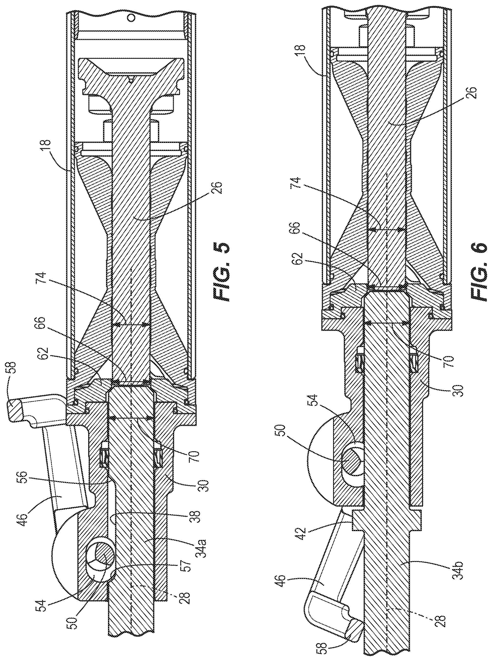
FIG. 5 is a cross-sectional view of portion of the percussion tool of FIG. 1 with a portion of the chisel of FIG. 3 inserted into a tool holder of the percussion tool.
FIG. 6 is a cross-sectional view of a portion of the percussion tool of FIG. 1 with a portion of the chisel of FIG. 4 inserted into the tool holder of the percussion tool.
FIG. 7 is a cross-sectional view of a portion of a percussion tool in accordance with yet another embodiment of the invention, illustrating a portion of the chisel of FIG. 3 inserted into a tool holder of the percussion tool.
FIG. 8 is a cross-sectional view of a portion of the percussion tool of FIG. 7 with a portion of the chisel of FIG. 4 inserted into the tool holder of the percussion tool.
FIG. 9 is a top perspective view of another embodiment of a handle of a tool holder for use with the percussion tool of FIG. 1.
FIG. 10 is a bottom perspective view of the handle of FIG. 9.
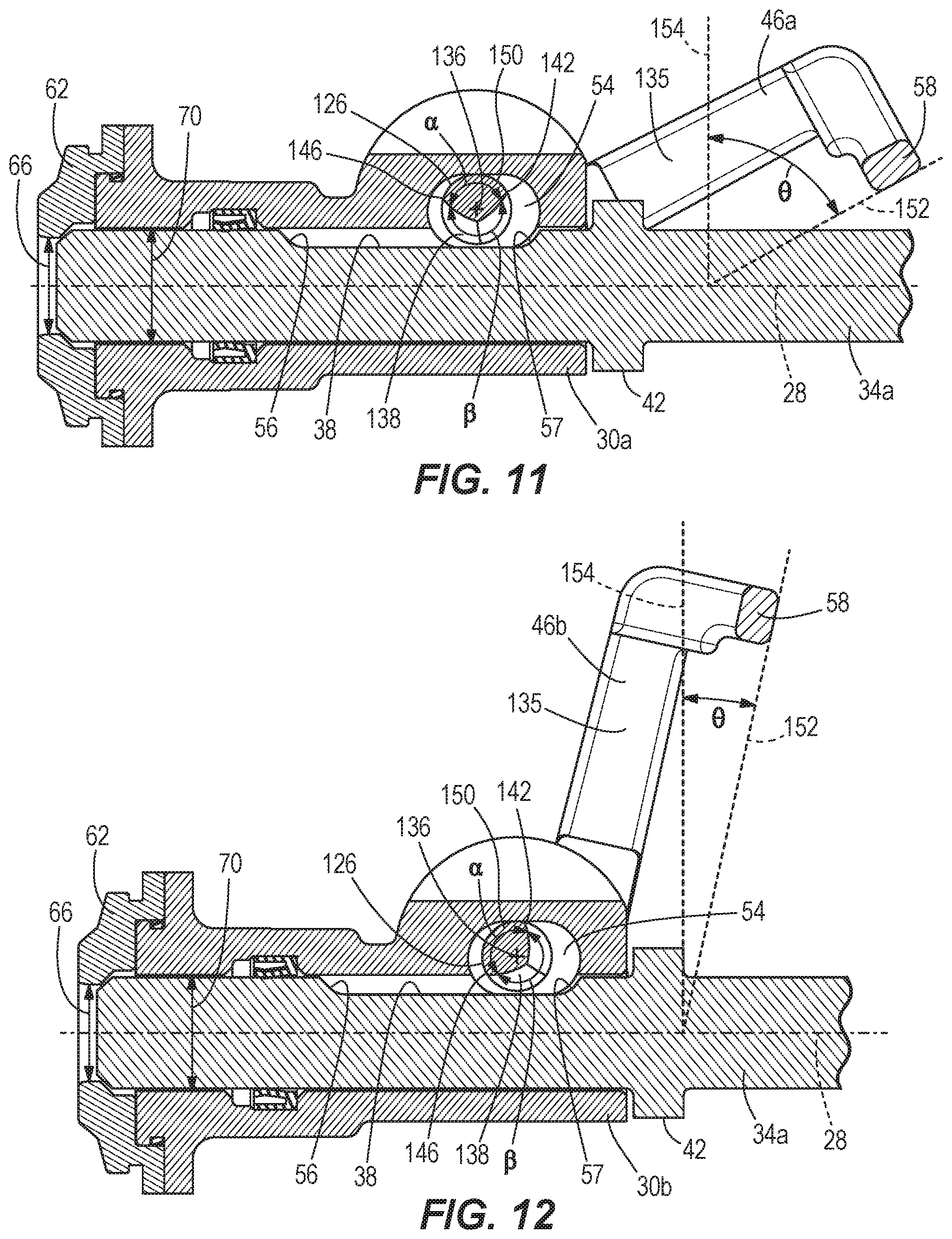
FIG. 11 is a cross-sectional view of another embodiment of a tool holder including the handle of FIG. 9, with portions removed.
FIG. 12 is a cross-sectional view of another embodiment of a tool holder for use with the percussion tool of FIG. 1.
Before any embodiments of the invention are explained in detail, it is to be understood that the invention is not limited in its application to the details of construction and the arrangement of components set forth in the following description or illustrated in the following drawings. The invention is capable of other embodiments and of being practiced or of being carried out in various ways. Also, it is to be understood that the phraseology and terminology used herein is for the purpose of description and should not be regarded as limiting.
DETAILED DESCRIPTION
With reference to FIGS. 1 and 2, a percussion tool 10, such as a breaker, includes a housing 14 having a cylinder portion 18. A percussion mechanism 22 is disposed in the housing 10 and can be any suitable percussion mechanism, including but not limited to pneumatic, hydraulic, motor-driven, or electromagnetic. The percussion mechanism 22 includes a striker 26 supported for reciprocation along a longitudinal axis 28 in the cylinder portion 18.
A tool holder 30 for holding a chisel 34a, 34b is coupled to the cylinder portion 18. As will be explained in further detail below, the tool holder 30 is adapted to hold a variety of chisels. For example, the tool holder 30 is adapted to hold a chisel 34a with a radially inward-extending longitudinal groove 38 as shown in FIG. 3. The groove 38 is parallel with the longitudinal axis 28 when the chisel 34a is received in the tool holder 30. The tool holder 30 is also adapted to hold a chisel 34b that has a radially outward-extending flange 42 instead of a longitudinal groove, as shown in FIG. 4. The percussion mechanism 22 is configured to impart repeated axial impacts to the chisel 34a, 34b via the striker 26, so that a breaking operation or chiseling operation may be performed on a workpiece or surface.
The tool holder 30 includes a rotatable handle 46 that can rotate between a first position shown in FIGS. 1, 2, 5 and 7, and a second position shown in FIGS. 6 and 8. The handle 46 includes an eccentric pin 50 rotatable therewith within a lateral recess 54 of the tool holder 30. If an operator elects to use chisel 34a with the percussion tool 10, rotation of the handle 46 to the first position causes the eccentric pin 50 to move radially inward within the recess 54, thereby engaging the longitudinal groove 38. Thus, if the operator tips the percussion tool 10 in such a manner that the chisel 34a might be caused to fall out of the tool holder 30, the eccentric pin 50 will contact a rear end 56 of the longitudinal groove 38 to prevent the chisel 34a from falling out. During operation of the percussion tool 10, as the striker 26 imparts axial blows to the chisel 34a along the longitudinal axis 28, the chisel 34a reciprocates within the tool holder 30 between forward and rearward positions where the eccentric pin 50 is maintained between the rear end 56 of the longitudinal groove and an opposite front end 57 of the longitudinal groove 38.
The handle 46 also includes a finger 58. If an operator elects to use chisel 34b with the percussion tool 10, the handle 46 is rotated to the second positon in which the finger 58 abuts the chisel 34b. As shown in FIGS. 6 and 8, rotation of the handle 46 to the second position also causes the eccentric pin 50 to move radially outward in the recess 54, so as to avoid interfering with chisel 34b within the tool holder 30, because chisel 34b does not have a longitudinal groove. Thus, if the operator tips the percussion tool 10 in such a manner that the chisel 34b might be caused to fall out of the tool holder 30, the finger 58 will contact the radially outward-extending flange 42 and prevent the chisel 34b from falling out.
A radially inward-extending flange 62 with an inner diameter 66 is located between the cylinder portion 18 and the tool holder 30. In a first embodiment of the invention shown in FIGS. 5 and 6, the inner diameter 66 of the flange 62 is less than an outer diameter 70 of either of the chisels 34a, 34b, and greater than an outer diameter 74 of the striker 26. Thus, when an operator inserts either of the chisels 34a, 34b into the tool holder 30, movement of the chisels 34a, 34b within the tool holder 30 toward the percussion mechanism 22 is stopped in response to the chisels 34a, 34b abutting the flange 62 (as shown in each of FIGS. 5 and 6).
In another embodiment of a percussion tool shown in FIGS. 7 and 8, with like features being identified with like reference numerals, the tool holder 30 includes a recess 98 to accommodate an axially moveable sleeve 102. The sleeve 102 has a first end 106 with a first end outer diameter 110 that is greater than the inner diameter 66 of the flange 62. The sleeve 102 has an opposite second end 114 with a second end inner diameter 118 that is less than the outer diameter 70 of each of the chisels 34a, 34b. A striking end 116 of the striker 26 has an outer diameter 120 that is nominally less than the inner diameter 118 of the second end 114 of the sleeve 102, so that the striking end 116 may pass through the sleeve 102 and strike the chisels 34a, 34b. The chisels 34a, 34b axially move within a hollow portion 122 of the sleeve 102. Thus, when an operator inserts either of the chisels 34a, 34b into the tool holder 30, movement of the chisels 34a, 34b within the tool holder 30 toward the percussion mechanism 22 is stopped in response to the chisels 34a, 34b abutting the second end 114 of the sleeve 102, and the first end 106 of the sleeve 102 abutting the flange 62 (as shown in FIG. 8).
The flange 62 limits the distance the chisels 34a, 34b can be inserted into the tool holder 30, thereby preventing damage to the percussion mechanism 22 and allowing the point of impact between the striker 26 and the chisels 34a, 34b to remain consistent. Also, regardless of which of the chisels 34a, 34b an operator selects, the same percussion tool 10 may be used because the tool holder 30 is adapted to hold a variety of chisels.
FIG. 11 illustrates another embodiment of a tool holder 30a for use with the breaker 10 of FIG. 1, with like components shown with like reference numerals. The tool holder 30a includes a handle 46a having a rod 126 extending between opposite ends 130, 134 of the handle 46a (see also FIGS. 9 and 10), two legs 135 respectively extending from the opposite ends 130, 134, and the finger 58 extending between the legs 135 and in a direction approximately perpendicular to the legs 135. The rod 126 extends through the recess 54 of the tool holder 30a and defines an axis of rotation 136 about which the handle 46a rotates with respect to the tool holder 30a. The rod 126 is cylindrical and has a recessed portion 138 defined between two edges 142, 146 on the circumference of the rod 126. Opposite the recess 138, an arcuate portion 150 is defined between the two edges 142, 146 along the circumference of the rod 126. As shown in FIG. 12, with respect to the axis of rotation 136, the arcuate portion 150 defines an angle .alpha. that is slightly less than 180 degrees about the circumference of the rod 126. Correspondingly, the recess 138 defines an angle .beta. that is slightly more than 180 degrees.
If an operator elects to use chisel 34a with the tool holder 30a, rotation of the handle 46a to the first position causes rod 126 to rotate such that the arcuate portion 142 contacts the chisel 34a within the longitudinal groove 38. Thus, if the operator tips the percussion tool 10 in such a manner that the chisel 34a might be caused to fall out of the tool holder 30a, the arcuate portion 150 will contact the rear end 56 of the longitudinal groove 38 to prevent the chisel 34a from falling out. During operation of the percussion tool 10, as the striker 26 imparts axial blows to the chisel 34a along the longitudinal axis 28, the chisel 34a reciprocates within the tool holder 30a between forward and rearward positions where the arcuate portion 150 is maintained between the rear end 56 of the longitudinal groove 38 and the front end 57 of the longitudinal groove 38.
To release the chisel 34a, the operator must rotate the handle 46a from a first position (having an orientation relative to axis 28 similar to that shown in FIGS. 1 and 2) in which the arcuate portion 150 is located at least partially within the groove 38 of the chisel 34a to a second position shown in FIG. 11. Rotation of the handle 46a to the second position causes the rod 126 to rotate, thus rotating the arcuate portion 150 away from the longitudinal groove 38 and removing the arcuate portion 150 from the longitudinal groove 38 of the chisel 34a, and instead placing the recessed portion 138 in facing relationship with the longitudinal groove 38, thus allowing chisel 34a to be removed. As shown in FIG. 11, an angle .theta. is defined between a first reference plane 152 defined by handle 46a and a second reference plane 154 that is perpendicular to the longitudinal axis 28. In the embodiment of FIGS. 9-11, the angle .theta. is approximately 70 degrees. In the embodiment illustrated in FIG. 11, the first reference plane 152 is defined as tangent to the finger 58. In other embodiments, the first reference plane 152 could be defined as extending along the legs 135, and the second reference plane 154 would be shifted left, as viewed in FIG. 11. Regardless of where the reference plane 152 is defined on the handle 46a, if the handle 46a is rotated to a position intermediate the first and second positions, the first reference plane 152 would be co-planar with the second reference plane 154.
FIG. 12 illustrates another embodiment of a tool holder 30b for use with the breaker 10 of FIG. 1, with like components shown with like reference numerals. The tool holder 30b includes a handle 46b that is otherwise identical to the handle 46a except that the angle .alpha. defined by the arcuate portion 150 is approximately 110 degrees about the circumference of the rod 126. Thus, the recessed portion 138 defines an angle .beta. that is approximately 250 degrees. To release the chisel 34a, the operator must rotate the handle 46b from a first position (having an orientation relative to axis 28 similar to that shown in FIGS. 1 and 2) in which the arcuate portion 150 is located at least partially within the groove 38 of the chisel 34a to a second position shown in FIG. 12. In this embodiment of the tool holder 30b, the angle .theta. defined between the finger 58 of handle 46b and the plane 154 is approximately 10 degrees. Because the arc length of the arcuate portion 142 has been reduced to approximately 110 degrees in the embodiment of FIG. 12, the operator does not need to rotate the handle 46b as far as in the embodiment of the tool holder 30a shown in FIG. 11 to release the chisel 34a (70 degrees beyond the second reference plane 154 with the tool holder 30a versus 10 degrees beyond the second reference plane 154 with the tool holder 30b). Such an arrangement makes it faster and easier for the operator to change the chisels 34a, 34b used in the tool holder 30b. In the embodiment illustrated in FIG. 12, the first reference plane 152 is defined as tangent to the finger 58. In other embodiments, the first reference plane 152 could be defined as extending along the legs 135, and the second reference plane 154 would be shifted left, as viewed in FIG. 12. Regardless of where the reference plane 152 is defined on the handle 46b, if the handle 46b were rotated to a position intermediate the first and second positions, the first reference plane 152 would be co-planar with the second reference plane 154.
Various features of the invention are set forth in the following claims.
* * * * *
D00000
D00001
D00002
D00003
D00004
D00005
D00006
D00007
XML
uspto.report is an independent third-party trademark research tool that is not affiliated, endorsed, or sponsored by the United States Patent and Trademark Office (USPTO) or any other governmental organization. The information provided by uspto.report is based on publicly available data at the time of writing and is intended for informational purposes only.
While we strive to provide accurate and up-to-date information, we do not guarantee the accuracy, completeness, reliability, or suitability of the information displayed on this site. The use of this site is at your own risk. Any reliance you place on such information is therefore strictly at your own risk.
All official trademark data, including owner information, should be verified by visiting the official USPTO website at www.uspto.gov. This site is not intended to replace professional legal advice and should not be used as a substitute for consulting with a legal professional who is knowledgeable about trademark law.