Carbon black from natural gas
Hardman , et al. October 20, 2
U.S. patent number 10,808,097 [Application Number 15/262,539] was granted by the patent office on 2020-10-20 for carbon black from natural gas. This patent grant is currently assigned to MONOLITH MATERIALS, INC.. The grantee listed for this patent is MONOLITH MATERIALS, INC.. Invention is credited to Christopher J. -P. Cardinal, Robert J. Hanson, Ned J. Hardman, Alexander F. Hoermann, Peter L. Johnson, Roscoe W. Taylor.


| United States Patent | 10,808,097 |
| Hardman , et al. | October 20, 2020 |
Carbon black from natural gas
Abstract
Carbon nanoparticles made in a one step process. A method of making carbon black nanoparticles is described, including adding a hydrocarbon to a heated gas to produce carbon nanoparticles that are less than 1 micron volume equivalent sphere and have an Lc greater than 3.0 nm. Elastomer composites containing such particles are also described.
| Inventors: | Hardman; Ned J. (Woodside, CA), Taylor; Roscoe W. (San Mateo, CA), Hoermann; Alexander F. (Menlo Park, CA), Johnson; Peter L. (Mountain View, CA), Cardinal; Christopher J. -P. (Sunnyvale, CA), Hanson; Robert J. (San Carlos, CA) | ||||||||||
|---|---|---|---|---|---|---|---|---|---|---|---|
| Applicant: |
|
||||||||||
| Assignee: | MONOLITH MATERIALS, INC.
(Lincoln, NE) |
||||||||||
| Family ID: | 1000005125600 | ||||||||||
| Appl. No.: | 15/262,539 | ||||||||||
| Filed: | September 12, 2016 |
Prior Publication Data
| Document Identifier | Publication Date | |
|---|---|---|
| US 20170073522 A1 | Mar 16, 2017 | |
Related U.S. Patent Documents
| Application Number | Filing Date | Patent Number | Issue Date | ||
|---|---|---|---|---|---|
| 62218137 | Sep 14, 2015 | ||||
| Current U.S. Class: | 1/1 |
| Current CPC Class: | C01B 32/15 (20170801); C08K 3/04 (20130101); C08J 5/005 (20130101); C09C 1/485 (20130101); C08K 3/04 (20130101); C08L 21/00 (20130101); C01P 2004/61 (20130101); C01P 2002/77 (20130101); C09C 1/50 (20130101); C08K 2201/003 (20130101); C01P 2004/62 (20130101); C01P 2006/19 (20130101); C01P 2006/12 (20130101); C08K 2201/011 (20130101); C01P 2006/80 (20130101); C01P 2004/64 (20130101); C08J 2321/00 (20130101); C01P 2004/04 (20130101); C01P 2004/32 (20130101) |
| Current International Class: | C09C 1/52 (20060101); C01B 32/15 (20170101); C08K 3/04 (20060101); C09C 1/48 (20060101); C08J 5/00 (20060101); C09C 1/50 (20060101) |
| Field of Search: | ;524/495 |
References Cited [Referenced By]
U.S. Patent Documents
| 1339225 | May 1920 | Rose |
| 1536612 | May 1925 | Lewis |
| 1597277 | August 1926 | Jakowsky |
| 2062358 | September 1932 | Frolich |
| 2002003 | May 1935 | Eisenhut et al. |
| 2039312 | May 1936 | Goldman et al. |
| 2393106 | January 1946 | Johnson et al. |
| 2557143 | June 1951 | Royster |
| 2572851 | October 1951 | Gardner et al. |
| 2603669 | July 1952 | Chappell |
| 2616842 | November 1952 | Sheer et al. |
| 2785964 | March 1957 | Pollock |
| 2850403 | September 1958 | Day |
| 2851403 | September 1958 | Hale |
| 2897071 | July 1959 | Gilbert |
| 2951143 | August 1960 | Anderson et al. |
| 3009783 | November 1961 | Sheer et al. |
| 3073769 | January 1963 | Doukas |
| 3288696 | November 1966 | Orbach |
| 3307923 | March 1967 | Ruble |
| 3309780 | March 1967 | Goins |
| 3331664 | July 1967 | Jordan |
| 3344051 | September 1967 | Latham, Jr. |
| 3308164 | October 1968 | Johnson |
| 3408164 | October 1968 | Johnson |
| 3409403 | November 1968 | Bjornson et al. |
| 3420632 | January 1969 | Ryan |
| 3431074 | March 1969 | Jordan |
| 3464793 | September 1969 | Jordan et al. |
| 3619140 | November 1971 | Morgan et al. |
| 3637974 | January 1972 | Tajbl et al. |
| 3673375 | June 1972 | Camacho |
| 3725103 | April 1973 | Jordan et al. |
| 3922335 | November 1975 | Jordan et al. |
| 3981654 | September 1976 | Rood et al. |
| 3981659 | September 1976 | Myers |
| 3984743 | October 1976 | Horie |
| 4028072 | June 1977 | Braun et al. |
| 4035336 | July 1977 | Jordan et al. |
| 4057396 | November 1977 | Matovich |
| 4075160 | February 1978 | Mills et al. |
| 4101639 | July 1978 | Surovikin et al. |
| 4199545 | April 1980 | Matovich |
| 4282199 | August 1981 | Lamond et al. |
| 4289949 | September 1981 | Raaness et al. |
| 4317001 | February 1982 | Silver et al. |
| 4372937 | February 1983 | Johnson |
| 4404178 | September 1983 | Johnson et al. |
| 4452771 | June 1984 | Hunt |
| 4431624 | August 1984 | Casperson |
| 4472172 | September 1984 | Sheer et al. |
| 4543470 | September 1985 | Santen et al. |
| 4553981 | November 1985 | Fuderer |
| 4601887 | July 1986 | Dorn et al. |
| 4678888 | July 1987 | Camacho et al. |
| 4689199 | August 1987 | Eckert et al. |
| 4755371 | July 1988 | Dickerson |
| 4765964 | August 1988 | Gravley et al. |
| 4787320 | November 1988 | Raaness et al. |
| 4864096 | September 1989 | Wolf et al. |
| 4977305 | December 1990 | Severance, Jr. |
| 5039312 | August 1991 | Hollis, Jr. et al. |
| 5045667 | September 1991 | Iceland et al. |
| 5046145 | September 1991 | Drouet |
| 5105123 | April 1992 | Ballou |
| 5147998 | September 1992 | Tsantrizos et al. |
| 5206880 | April 1993 | Olsson |
| 5352289 | October 1994 | Weaver et al. |
| 5399957 | March 1995 | Vierboom et al. |
| 5427762 | June 1995 | Steinberg et al. |
| 5476826 | December 1995 | Greenwald et al. |
| 5481080 | January 1996 | Lynum et al. |
| 5486674 | January 1996 | Lynum et al. |
| 5500501 | March 1996 | Lynum et al. |
| 5527518 | June 1996 | Lynum |
| 5593644 | January 1997 | Norman et al. |
| 5604424 | February 1997 | Shuttleworth |
| 5611947 | March 1997 | Vavruska |
| 5673285 | September 1997 | Wittle et al. |
| 5717293 | February 1998 | Sellers |
| 5725616 | March 1998 | Lynum et al. |
| 5749937 | May 1998 | Detering et al. |
| 5935293 | August 1999 | Detering et al. |
| 5951960 | September 1999 | Lynum et al. |
| 5989512 | November 1999 | Lynum et al. |
| 5997837 | December 1999 | Lynum et al. |
| 6068827 | May 2000 | Lynum et al. |
| 6099696 | August 2000 | Schwob et al. |
| 6188187 | February 2001 | Harlan |
| 6197274 | March 2001 | Mahmud et al. |
| 6277350 | August 2001 | Gerspacher |
| 6358375 | March 2002 | Schwob |
| 6380507 | April 2002 | Childs |
| 6395197 | May 2002 | Detering et al. |
| 6403697 | June 2002 | Mitsunaga et al. |
| 6441084 | August 2002 | Lee et al. |
| 6442950 | September 2002 | Tung |
| 6444727 | September 2002 | Yamada et al. |
| 6602920 | August 2003 | Hall et al. |
| 6703580 | March 2004 | Brunet et al. |
| 6773689 | August 2004 | Lynum et al. |
| 6955707 | October 2005 | Ezell et al. |
| 7167240 | January 2007 | Stagg |
| 7294314 | November 2007 | Graham |
| 7312415 | December 2007 | Ohmi et al. |
| 7360309 | April 2008 | Vaidyanathan et al. |
| 7431909 | October 2008 | Rumpf et al. |
| 7452514 | November 2008 | Fabry et al. |
| 7462343 | December 2008 | Lynum et al. |
| 7563525 | July 2009 | Ennis |
| 7655209 | February 2010 | Rumpf et al. |
| 7777151 | August 2010 | Kuo |
| 7968191 | June 2011 | Hampden-Smith et al. |
| 8147765 | April 2012 | Muradov et al. |
| 8221689 | July 2012 | Boutot et al. |
| 8257452 | September 2012 | Menzel |
| 8277739 | October 2012 | Monsen et al. |
| 8323793 | December 2012 | Hamby et al. |
| 8443741 | May 2013 | Chapman et al. |
| 8471170 | June 2013 | Li et al. |
| 8486364 | July 2013 | Vanier et al. |
| 8501148 | August 2013 | Belmont et al. |
| 8581147 | November 2013 | Kooken et al. |
| 8710136 | April 2014 | Yurovskaya et al. |
| 8771386 | July 2014 | Licht et al. |
| 8784617 | July 2014 | Novoselov et al. |
| 8850826 | October 2014 | Ennis |
| 8871173 | October 2014 | Nester et al. |
| 8911596 | December 2014 | Vancina |
| 9095835 | August 2015 | Skoptsov et al. |
| 9315735 | April 2016 | Cole et al. |
| 9445488 | September 2016 | Foret |
| 9574086 | February 2017 | Johnson et al. |
| 10100200 | October 2018 | Johnson et al. |
| 10138378 | November 2018 | Hoermman et al. |
| 10370539 | August 2019 | Johnson et al. |
| 2001/0029888 | October 2001 | Sindarrajan et al. |
| 2001/0039797 | November 2001 | Cheng |
| 2002/0000085 | January 2002 | Hall et al. |
| 2002/0050323 | May 2002 | Moisan et al. |
| 2002/0051903 | May 2002 | Masuko et al. |
| 2002/0157559 | October 2002 | Brunet et al. |
| 2003/0103858 | June 2003 | Baran et al. |
| 2003/0152184 | August 2003 | Shehane et al. |
| 2004/0047779 | March 2004 | Denison |
| 2004/0071626 | April 2004 | Smith et al. |
| 2004/0081862 | April 2004 | Herman |
| 2004/0148860 | August 2004 | Fletcher |
| 2004/0168904 | September 2004 | Anazawa et al. |
| 2004/0211760 | October 2004 | Delzenne et al. |
| 2004/0216559 | November 2004 | Kim et al. |
| 2004/0247509 | December 2004 | Newby |
| 2005/0063892 | March 2005 | Tandon et al. |
| 2005/0079119 | April 2005 | Kawakami et al. |
| 2005/0230240 | October 2005 | Dubrovsky et al. |
| 2006/0034748 | February 2006 | Lewis et al. |
| 2006/0037244 | February 2006 | Clawson |
| 2006/0068987 | March 2006 | Bollepalli et al. |
| 2006/0107789 | May 2006 | Deegan et al. |
| 2006/0155157 | July 2006 | Zarrinpashne et al. |
| 2006/0226538 | October 2006 | Kawata |
| 2006/0239890 | October 2006 | Chang et al. |
| 2007/0140004 | June 2007 | Marotta et al. |
| 2007/0183959 | August 2007 | Charlier et al. |
| 2007/0270511 | November 2007 | Melnichuk et al. |
| 2007/0293405 | December 2007 | Zhang et al. |
| 2008/0041829 | February 2008 | Blutke et al. |
| 2008/0121624 | May 2008 | Belashchenko et al. |
| 2008/0159947 | July 2008 | Yurovskaya et al. |
| 2008/0169183 | July 2008 | Hertel et al. |
| 2008/0182298 | July 2008 | Day |
| 2008/0226538 | September 2008 | Rumpf et al. |
| 2008/0279749 | November 2008 | Probst et al. |
| 2008/0292533 | November 2008 | Belmont et al. |
| 2009/0014423 | January 2009 | Li et al. |
| 2009/0090282 | April 2009 | Gold et al. |
| 2009/0142250 | June 2009 | Fabry et al. |
| 2009/0155157 | June 2009 | Stenger et al. |
| 2009/0173252 | July 2009 | Nakata et al. |
| 2009/0208751 | August 2009 | Green et al. |
| 2009/0230098 | September 2009 | Salsich et al. |
| 2010/0147188 | June 2010 | Mamak et al. |
| 2010/0249353 | September 2010 | Macintosh et al. |
| 2011/0036014 | February 2011 | Tsangaris et al. |
| 2011/0071692 | March 2011 | D'Amato et al. |
| 2011/0071962 | March 2011 | Lim |
| 2011/0076608 | March 2011 | Bergemann et al. |
| 2011/0138766 | June 2011 | Elkady et al. |
| 2011/0155703 | June 2011 | Winn |
| 2011/0180513 | July 2011 | Luhrs et al. |
| 2011/0239542 | October 2011 | Liu et al. |
| 2012/0018402 | January 2012 | Carducci et al. |
| 2012/0025693 | February 2012 | Wang et al. |
| 2012/0201266 | August 2012 | Boulos et al. |
| 2012/0232173 | September 2012 | Juranitch et al. |
| 2012/0292794 | November 2012 | Prabhu et al. |
| 2013/0039841 | February 2013 | Nester et al. |
| 2013/0062195 | March 2013 | Samaranayake et al. |
| 2013/0062196 | March 2013 | Sin |
| 2013/0092525 | April 2013 | Li et al. |
| 2013/0194840 | August 2013 | Huselstein et al. |
| 2013/0292363 | November 2013 | Hwang et al. |
| 2013/0323614 | December 2013 | Chapman et al. |
| 2013/0340651 | December 2013 | Wampler et al. |
| 2014/0000488 | January 2014 | Sekiyama et al. |
| 2014/0057166 | February 2014 | Yokoyama et al. |
| 2014/0131324 | May 2014 | Shipulski et al. |
| 2014/0190179 | July 2014 | Barker et al. |
| 2014/0224706 | August 2014 | Do et al. |
| 2014/0227165 | August 2014 | Hung et al. |
| 2014/0248442 | September 2014 | Luizi et al. |
| 2014/0290532 | October 2014 | Rodriguez et al. |
| 2014/0294716 | October 2014 | Susekov et al. |
| 2014/0339478 | November 2014 | Probst et al. |
| 2014/0357092 | December 2014 | Singh |
| 2014/0373752 | December 2014 | Hassinen et al. |
| 2015/0004516 | January 2015 | Kim et al. |
| 2015/0044516 | February 2015 | Kyrlidis et al. |
| 2015/0056516 | February 2015 | Hellring et al. |
| 2015/0064099 | March 2015 | Nester et al. |
| 2015/0180346 | June 2015 | Yuzurihara et al. |
| 2015/0210856 | July 2015 | Johnson et al. |
| 2015/0210857 | July 2015 | Johnson et al. |
| 2015/0210858 | July 2015 | Hoermann et al. |
| 2015/0211378 | July 2015 | Johnson et al. |
| 2015/0217940 | August 2015 | Si et al. |
| 2015/0218383 | August 2015 | Johnson et al. |
| 2015/0223314 | August 2015 | Hoermann et al. |
| 2015/0252168 | September 2015 | Schuck et al. |
| 2016/0030856 | February 2016 | Kaplan et al. |
| 2016/0210856 | July 2016 | Assenbaum et al. |
| 2016/0243518 | August 2016 | Spitzl |
| 2016/0293959 | October 2016 | Blizanac et al. |
| 2017/0034898 | February 2017 | Moss et al. |
| 2017/0037253 | February 2017 | Hardman et al. |
| 2017/0058128 | March 2017 | Johnson et al. |
| 2017/0066923 | March 2017 | Hardman et al. |
| 2017/0073522 | March 2017 | Hardman et al. |
| 2017/0349758 | December 2017 | Johnson |
| 2018/0015438 | January 2018 | Taylor et al. |
| 2018/0016441 | January 2018 | Taylor et al. |
| 2018/0022925 | January 2018 | Hardman et al. |
| 2019/0048200 | February 2019 | Johnson et al. |
| 2019/0100658 | April 2019 | Taylor et al. |
| 28970/71 | Nov 1972 | AU | |||
| 830378 | Dec 1969 | CA | |||
| 964405 | Mar 1975 | CA | |||
| 2 353 752 | Jan 2003 | CA | |||
| 2 621 749 | Aug 2009 | CA | |||
| 203269847 | Nov 2013 | CH | |||
| 1458966 | Nov 2003 | CN | |||
| 1644650 | Jul 2005 | CN | |||
| 101092691 | Dec 2007 | CN | |||
| 102007186 | Apr 2011 | CN | |||
| 102060281 | May 2011 | CN | |||
| 102108216 | Jun 2011 | CN | |||
| 102993788 | Mar 2013 | CN | |||
| 103160149 | Jun 2013 | CN | |||
| 103391678 | Nov 2013 | CN | |||
| 211457 | Jul 1984 | DE | |||
| 198 07 224 | Aug 1999 | DE | |||
| 200300389 | Dec 2003 | EA | |||
| 0325689 | Aug 1989 | EP | |||
| 0 616 600 | Sep 1994 | EP | |||
| 0 635 044 | Feb 1996 | EP | |||
| 0 635 043 | Jun 1996 | EP | |||
| 0 861 300 | Sep 1998 | EP | |||
| 1017622 | Jul 2000 | EP | |||
| 1088854 | Apr 2001 | EP | |||
| 1188801 | Mar 2002 | EP | |||
| 2 891 434 | Mar 2007 | FR | |||
| 395893 | Jul 1933 | GB | |||
| 987498 | Mar 1965 | GB | |||
| 1068519 | May 1967 | GB | |||
| 1 400 266 | Jul 1975 | GB | |||
| 1 492 346 | Nov 1977 | GB | |||
| 2419883 | May 2006 | GB | |||
| H04228270 | Aug 1992 | JP | |||
| 6-322615 | Nov 1994 | JP | |||
| H09316645 | Dec 1997 | JP | |||
| H11123562 | May 1999 | JP | |||
| 2001253974 | Sep 2001 | JP | |||
| 2004-300334 | Oct 2004 | JP | |||
| 2005-243410 | Sep 2005 | JP | |||
| 2005235709 | Sep 2005 | JP | |||
| 10-2008-105344 | Dec 2008 | KR | |||
| 2014-0075261 | Jun 2014 | KR | |||
| 2425795 | Aug 2011 | RU | |||
| 2488984 | Jul 2013 | RU | |||
| 200418933 | Oct 2004 | TW | |||
| 2017/027385 | Feb 1917 | WO | |||
| 93/12031 | Jun 1993 | WO | |||
| 93/18094 | Sep 1993 | WO | |||
| 93/20153 | Oct 1993 | WO | |||
| WO-9320152 | Oct 1993 | WO | |||
| 93/23331 | Nov 1993 | WO | |||
| 1994/008747 | Apr 1994 | WO | |||
| 97/03133 | Jan 1997 | WO | |||
| WO-9813428 | Apr 1998 | WO | |||
| WO-0018682 | Apr 2000 | WO | |||
| WO-0224819 | Mar 2002 | WO | |||
| WO-03014018 | Feb 2003 | WO | |||
| WO-2004083119 | Sep 2004 | WO | |||
| 2 937 029 | Apr 2010 | WO | |||
| 2012/015313 | Feb 2012 | WO | |||
| 2012/067546 | May 2012 | WO | |||
| 2012/094743 | Jul 2012 | WO | |||
| 2012/149170 | Nov 2012 | WO | |||
| 2013/134093 | Sep 2013 | WO | |||
| 2013/184074 | Dec 2013 | WO | |||
| 2013/185219 | Dec 2013 | WO | |||
| 2014/000108 | Jan 2014 | WO | |||
| 2014/012169 | Jan 2014 | WO | |||
| 2015/049008 | Apr 2015 | WO | |||
| WO-2015051893 | Apr 2015 | WO | |||
| WO-2015093947 | Jun 2015 | WO | |||
| 2015/116797 | Aug 2015 | WO | |||
| 2015/116798 | Aug 2015 | WO | |||
| 2015/116800 | Aug 2015 | WO | |||
| 2015/116807 | Aug 2015 | WO | |||
| 2015/116811 | Aug 2015 | WO | |||
| 2015/116943 | Aug 2015 | WO | |||
| 2016/012367 | Jan 2016 | WO | |||
| WO-2016014641 | Jan 2016 | WO | |||
| 2016/126598 | Aug 2016 | WO | |||
| 2016/126599 | Aug 2016 | WO | |||
| 2016/126600 | Aug 2016 | WO | |||
| 2017/019683 | Feb 2017 | WO | |||
| 2017/034980 | Mar 2017 | WO | |||
| 2017/044594 | Mar 2017 | WO | |||
| 2017/048621 | Mar 2017 | WO | |||
| 2017/190015 | Nov 2017 | WO | |||
| 2017/190045 | Nov 2017 | WO | |||
| WO-2018165483 | Sep 2018 | WO | |||
| WO-2018195460 | Oct 2018 | WO | |||
Other References
|
Gago et al., Trends in Fullerene Research, Published by Nova Science Publishers, Inc. (2007), pp. 1-46. cited by examiner . Non-Final Office Action dated May 2, 2017 in U.S. Appl. No. 14/610,299. cited by applicant . Ex Parte Quayle Action dated May 19, 2017 in U.S. Appl. No. 14/601,761. cited by applicant . Extended European Search Report from EP Application No. 15742910.1 dated Jul. 18, 2017. cited by applicant . Supplementary Partial European Search Report from EP Application No. 15743214.7 dated Sep. 12, 2017. cited by applicant . ISR and Written Opinion from PCT/US2017/030139, dated Jul. 19, 2017. cited by applicant . ISR and Written Opinion from PCT/US2017/030179, dated Jul. 27, 2017. cited by applicant . Reese, J. (2017). Resurgence in American manufacturing will be led by the rubber and tire industry. Rubber World. 255. 18-21 and 23. cited by applicant . Non-Final Office Action dated Feb. 27, 2017 in U.S. Appl. No. 14/591,476. cited by applicant . Extended European Search Report from EP Application No. 15743214.7 dated Jan. 16, 2018. cited by applicant . Chiesa P, Lozza G, Mazzocchi L. Using Hydrogen as Gas Turbine Fuel. ASME. J. Eng. Gas Turbines Power. 2005;127(1):73-80. doi:10.1115/1.1787513. cited by applicant . Tsujikawa, Y., and T. Sawada. "Analysis of a gas turbine and steam turbine combined cycle with liquefied hydrogen as fuel." International Journal of Hydrogen Energy 7.6 (1982): 499-505. cited by applicant . Search report from RU2016135213, dated Feb. 12, 2018. cited by applicant . Non-Final Office Action dated Jan. 16, 2018 in U.S. Appl. No. 14/591,528. cited by applicant . Bakken, Jon Arne, et al. "Thermal plasma process development in Norway." Pure and applied Chemistry 70.6 (1998): 1223-1228. cited by applicant . Polman, E. A., J. C. De Laat, and M. Crowther. "Reduction of CO2 emissions by adding hydrogen to natural gas." IEA Green House Gas R&D programme (2003). cited by applicant . Verfondern, K., "Nuclear Energy for Hydrogen Production", Schriften des Forschungzentrum Julich, vol. 58, 2007. cited by applicant . U.S. Environmental Protection Agency, "Guide to Industrial Assessments for Pollution Prevention and Energy Efficiency," EPA 625/R-99/003, 1999. cited by applicant . Breeze, P. "Raising steam plant efficiency--Pushing the steam cycle boundaries." PEI Magazine 20.4 (2012). cited by applicant . Final Office Action dated Oct. 13, 2017 in U.S. Appl. No. 14/591,476. cited by applicant . Final Office Action dated Oct. 13, 2017 in U.S. Appl. No. 14/591,541. cited by applicant . Notice of Allowance dated Jan. 18, 2018 in U.S. Appl. No. 14/601,761. cited by applicant . Correced Notice of Allowance dated Feb. 9, 2018 in U.S. Appl. No. 14/601,761. cited by applicant . Final Office Action dated Sep. 19, 2017 in U.S. Appl. No. 15/221,088. cited by applicant . Non-Final Office Action dated Jan. 9, 2018 in U.S. Appl. No. 15/259.884. cited by applicant . Non-Final Office Action dated Apr. 20, 2018 in U.S. Appl. No. 15/221,088. cited by applicant . ISR and Written Opinion from PCT/US2015/013482, dated Jun. 17, 2015. cited by applicant . ISR and Written Opinion from PCT/US2015/013505, dated May 11, 2015. cited by applicant . ISR and Written Opinion from PCT/US2015/013487, dated Jun. 16, 2015. cited by applicant . Donnet, Basal and Wang, "Carbon Black", New York: Marcel Dekker, 1993 pp. 46, 47 and 54. cited by applicant . Boehm, HP, "Some Aspects of Surface Chemistry of Carbon Blacks and Other Carbons", Carbon 1994, p. 759. cited by applicant . "Carbon Black Elastomer Interaction" Rubber Chemistry and Technology, 1991, pp. 19-39. cited by applicant . "The Impact of a Fullerene-Like Concept in Carbon Black Science", Carbon, 2002, pp. 157-162. cited by applicant . ISR and Written Opinion from PCT/US2015/013510, dated Apr. 22, 2015. cited by applicant . ISR and Written Opinion from PCT/US2016/015939, dated Jun. 3, 2016. cited by applicant . ISR and Written Opinion from PCT/US2016/015941, dated Feb. 22, 2016. cited by applicant . ISR and Written Opinion from PCT/US2016/015942, dated Apr. 11, 2016. cited by applicant . ISR and Written Opinion from PCT/US2016/044039, dated Oct. 6, 2016. cited by applicant . ISR and Written Opinion from PCT/US2016/045793, dated Oct. 18, 2016. cited by applicant . ISR and Written Opinion from PCT/US2016/050728, dated Nov. 18, 2016. cited by applicant . ISR and Written Opinion from PCT/US2016/051261, dated Nov. 18, 2016. cited by applicant . ISR and Written Opinion from PCT/US2015/013484, dated Apr. 22, 2015. cited by applicant . AP 42, Fifth Edition, vol. I, Chapter 6: Organic Chemical Process Industry, Section 6.1: Carbon Black. cited by applicant . Fulcheri, et al. "Plasma processing: a step towards the production of new grades of carbon black." Carbon 40.2 (2002): 169-176. cited by applicant . Grivei, et al. A clean process for carbon nanoparticles and hydrogen production from plasma hydrocarbon cracking. Publishable Report, European Commission JOULE III Programme, Project No. JOE3-CT97-0057, circa 2000. cited by applicant . Fabry, et al. "Carbon black processing by thermal plasma. Analysis of the particle formation mechanism." Chemical Engineering Science 56.6 (2001): 2123-2132. cited by applicant . Pristavita, et al. "Carbon nanoparticle production by inductively coupled thermal plasmas: controlling the thermal history of particle nucleation." Plasma Chemistry and Plasma Processing 31.6 (2011): 851-866. cited by applicant . Cho, et al. "Conversion of natural gas to hydrogen and carbon black by plasma and application of plasma black." Symposia--American Chemical Society, Div. Fuel Chem. vol. 49. 2004. cited by applicant . Pristavita, et al. "Carbon blacks produced by thermal plasma: the influence of the reactor geometry on the product morphology." Plasma Chemistry and Plasma Processing 30.2 (2010): 267-279. cited by applicant . Pristavita, et al. "Volatile Compounds Present in Carbon Blacks Produced by Thermal Plasmas." Plasma Chemistry and Plasma Processing 31.6 (2011): 839-850. cited by applicant . Garberg, et al. "A transmission electron microscope and electron diffraction study of carbon nanodisks." Carbon 46.12 (2008): 1535-1543. cited by applicant . Knaapila, et al. "Directed assembly of carbon nanocones into wires with an epoxy coating in thin films by a combination of electric field alignment and subsequent pyrolysis." Carbon 49.10 (2011): 3171-3178. cited by applicant . Krishnan, et al. "Graphitic cones and the nucleation of curved carbon surfaces." Nature 388.6641 (1997): 451-454. cited by applicant . Hoyer, et al. "Microelectromechanical strain and pressure sensors based on electric field aligned carbon cone and carbon black particles in a silicone elastomer matrix." Journal of Applied Physics 112.9 (2012): 094324. cited by applicant . Naess, Stine Nalum, et al. "Carbon nanocones: wall structure and morphology." Science and Technology of advanced materials (2016), 7 pages. cited by applicant . Fulcheri, et al. "From methane to hydrogen, carbon black and water." International journal of hydrogen energy 20.3 (1995): 197-202. cited by applicant . ISR and Written Opinion from PCT/US2016/047769, dated Dec. 30, 2016. cited by applicant . D.L. Sun, F. Wang, R.Y. Hong, C.R. Xie, Preparation of carbon black via arc discharge plasma enhanced by thermal pyrolysis, Diamond & Related Materials (2015), doi: 10.1016/j.diamond.2015.11.004, 47 pages. cited by applicant . ISR and Written Opinion from PCT/US2015/013794, dated Jun. 19, 2015. cited by applicant . Biscoe, et al., An X-Ray study of carbon black. Journal of Applied physics, 1942; 13: 364-371. cited by applicant . Co-pending U.S. Appl. No. 16/180,635, filed Nov. 5, 2018. cited by applicant . EP16847102.7 Extended European Search Report dated Jul. 5, 2019. cited by applicant . U.S. Appl. No. 15/241,771 Office Action dated Mar. 13, 2019. cited by applicant . U.S. Appl. No. 15/259,884 Office Action dated May 31, 2019. cited by applicant . Co-pending U.S. Appl. No. 16/097,035, filed Oct. 26, 2018. cited by applicant . Co-pending U.S. Appl. No. 16/563,008, filed Sep. 6, 2019. cited by applicant . Co-pending U.S. Appl. No. 16/807,550, filed Mar. 3, 2020. cited by applicant . Donnet, et al., Observation of Plasma-Treated Carbon Black Surfaces by Scanning Tunnelling Microscopy. Carbon (1994) 32(2): 199-206. cited by applicant . EP16845031.0 Extended European Search Report dated Mar. 18, 2019. cited by applicant . EP17790549.4 Extended European Search Report dated Nov. 26, 2019. cited by applicant . EP17790570.0 Extended European Search Report dated Nov. 8, 2019. cited by applicant . Extended European Search Report for EP Application No. 16747055.8, dated Jun. 27, 2018. cited by applicant . Extended European Search Report for EP Application No. 16747056.6 dated Jun. 27, 2018. cited by applicant . Extended European Search Report for EP Application No. 16747057.4 dated Oct. 9, 2018. cited by applicant . Extended European Search Report for EP Application No. 16835697.0 dated Nov. 28, 2018. cited by applicant . Gago, et al., Growth mechanisms and structure of fullerene-like carbon-based thin films: superelastic materials for tribological applications. Trends in Fullerene Research, Published by Nova Science Publishers, Inc. (2007): 1-46. cited by applicant . Hernandez, et al. Comparison of carbon nanotubes and nanodisks as percolative fillers in electrically conductive composites. Scripta Materialia 58 (2008) 69-72. cited by applicant . International Preliminary Report on Patentability for Application No. PCT/US2015/013482 dated Aug. 2, 2016. cited by applicant . International Preliminary Report on Patentability for Application No. PCT/US2015/013484 dated Aug. 2, 2016. cited by applicant . International Preliminary Report on Patentability for Application No. PCT/US2015/013487 dated Aug. 2, 2016. cited by applicant . International Preliminary Report on Patentability for Application No. PCT/US2015/013505 dated Aug. 2, 2016. cited by applicant . International Preliminary Report on Patentability for Application No. PCT/US2015/013510 dated Aug. 2, 2016. cited by applicant . International Preliminary Report on Patentability for Application No. PCT/US2017/030139 dated Oct. 30, 2018. cited by applicant . International Preliminary Report on Patentability for Application No. PCT/US2017/030179 dated Oct. 30, 2018. cited by applicant . International Search Report and Written Opinion for Application No. PCT/US2018/021627 dated May 31, 2018. cited by applicant . International Search Report and Written Opinion for Application No. PCT/US2018/028619 dated Aug. 9, 2018. cited by applicant . International Search Report and Written Opinion for Application No. PCT/US2018/048374 dated Nov. 21, 2018. cited by applicant . International Search Report and Written Opinion for Application No. PCT/US2018/048378 dated Dec. 20, 2018. cited by applicant . International Search Report and Written Opinion for Application No. PCT/US2018/048381 dated Dec. 14, 2018. cited by applicant . International Search Report for Application No. PCT/US2015/13482 dated Jun. 17, 2015. cited by applicant . International Search Report for Application No. PCT/US2015/13487 dated Jun. 16, 2015. cited by applicant . Larouche, et al.,Nitrogen Functionalization of Carbon Black in a Thermo-Convective Plasma Reactor. Plasma Chem Plasma Process (2011) 31: 635-647. cited by applicant . Medalia, et al., Tinting Strength of Carbon Black. Journal of Colloid and Interface Science 40.2. (1972). cited by applicant . Partial International Search Report for Application No. PCT/US2018/028619 dated Jun. 18, 2018. cited by applicant . PCT/US2018/021627 International Search Report and Written Opinion dated May 31, 2018. cited by applicant . PCT/US2018/028619 International Search Report and Written Opinion dated Aug. 9, 2018. cited by applicant . PCT/US2018/048374 International Search Report and Written Opinion dated Nov. 21, 2018. cited by applicant . PCT/US2018/057401 International Search Report and Written Opinion dated Feb. 15, 2019. cited by applicant . PCT/US2018/064538 International Search Report and Written Opinion dated Feb. 19, 2019. cited by applicant . PCT/US2019/025632 International Search Report and Written Opinion dated Jun. 24, 2019. cited by applicant . Reynolds, Electrode Resistance: How Important is Surface Area. Oct. 10, 2016. p. 3 para[0001]; Figure 3; Retrieved from http://electrotishing.net/2016/10/10/electrode-resistance-how-important-i- s-surface-area/ on May 8, 2018. cited by applicant . Translation of Official Notification of RU Application No. 2016135213 dated Feb. 12, 2018. cited by applicant . U.S. Appl. No. 14/591,541 Notice of Allowance dated Sep. 17, 2018. cited by applicant . U.S. Appl. No. 14/591,528 Office Action dated Jan. 17, 2019. cited by applicant . U.S. Appl. No. 15/548,346 Office Action dated Oct. 22, 2019. cited by applicant . U.S. Appl. No. 15/548,348 Office Action dated Apr. 25, 2019. cited by applicant . U.S. Appl. No. 14/591,476 Notice of Allowance dated Mar. 20, 2019. cited by applicant . U.S. Appl. No. 14/591,476 Office Action dated Jul. 11, 2016. cited by applicant . U.S. Appl. No. 14/591,476 Office Action dated Jun. 7, 2018. cited by applicant . U.S. Appl. No. 14/591,476 Office Action dated Mar. 16, 2016. cited by applicant . U.S. Appl. No. 14/591,528 Office Action dated Oct. 28, 2019. cited by applicant . U.S. Appl. No. 14/591,541 Notice of Allowance dated Jun. 7, 2018. cited by applicant . U.S. Appl. No. 14/591,541 Office Action dated Feb. 22, 2017. cited by applicant . U.S. Appl. No. 14/591,541 Office Action dated Jul. 14, 2016. cited by applicant . U.S. Appl. No. 14/591,541 Office Action dated Mar. 16, 2016. cited by applicant . U.S. Appl. No. 14/601,761 Notice of Allowance dated Feb. 9, 2018. cited by applicant . U.S. Appl. No. 14/601,761 Notice of Allowance dated Jun. 19, 2018. cited by applicant . U.S. Appl. No. 14/601,761 Notice of Allowance dated Oct. 11, 2018. cited by applicant . U.S. Appl. No. 14/601,761 Notice of Allowance dated Sep. 17, 2018. cited by applicant . U.S. Appl. No. 14/601,761 Office Action dated Apr. 14, 2016. cited by applicant . U.S. Appl. No. 14/601,761 Office Action dated Oct. 19, 2016. cited by applicant . U.S. Appl. No. 14/601,793 Notice of Allowance dated Oct. 7, 2016. cited by applicant . U.S. Appl. No. 14/601,793 Office Action dated Apr. 13, 2016. cited by applicant . U.S. Appl. No. 14/601,793 Office Action dated dated Aug. 3, 2016. cited by applicant . U.S. Appl. No. 14/610,299 Notice of Allowance dated Feb. 20, 2020. cited by applicant . U.S. Appl. No. 14/610,299 Office Action dated Sep. 25, 2018. cited by applicant . U.S. Appl. No. 15/221,088 Office Action dated Dec. 23, 2016. cited by applicant . U.S. Appl. No. 15/221,088 Office Action dated Dec. 4, 2019. cited by applicant . U.S. Appl. No. 15/221,088 Office Action dated Mar. 7, 2019. cited by applicant . U.S. Appl. No. 15/229,608 Office Action dated Apr. 8, 2019. cited by applicant . U.S. Appl. No. 15/229,608 Office Action dated Oct. 25, 2019. cited by applicant . U.S. Appl. No. 15/241,771 Office Action dated Jul. 6, 2018. cited by applicant . U.S. Appl. No. 15/241,771 Office Action dated Sep. 25, 2019. cited by applicant . U.S. Appl. No. 15/259,884 Office Action dated Feb. 25, 2020. cited by applicant . U.S. Appl. No. 15/259,884 Office Action dated Jan. 9, 2018. cited by applicant . U.S. Appl. No. 15/259,884 Office Action dated Oct. 11, 2018. cited by applicant . U.S. Appl. No. 15/410,283 Office Action dated Jan. 16, 2020. cited by applicant . U.S. Appl. No. 15/410,283 Office Action dated Jun. 7, 2018. cited by applicant . U.S. Appl. No. 15/410,283 Office Action dated Mar. 12, 2019. cited by applicant . U.S. Appl. No. 15/548,348 Notice of Allowance dated Dec. 12, 2019. cited by applicant . U.S. Appl. No. 15/548,352 Office Action dated Jan. 31, 2020. cited by applicant . U.S. Appl. No. 15/548,352 Office Action dated May 9, 2019. cited by applicant . U.S. Appl. No. 15/548,352 Office Action dated Oct. 10, 2018. cited by applicant . U.S. Appl. No. 16/159,144 Office Action dated Mar. 26, 2020. cited by applicant . Wikipedia, Heating Element. Oct. 14, 2016. p. 1 para[0001]. Retrieved from https://en.wikipedia.org/w/index.php?title=Heating_element&oldid=74427754- 0 on May 9, 2018. cited by applicant . Wikipedia, Joule Heating. Jan. 15, 2017. p. 1 para[0002]. Retrieved from https://en.wikipedia.org/w/index . Dhp?title=Joule_heating&oldid=760136650 on May 9, 2018. cited by applicant . U.S. Appl. No. 15/229,608 Office Action dated May 15, 2020. cited by applicant . U.S. Appl. No. 15/241,771 Office Action dated May 1, 2020. cited by applicant . U.S. Appl. No. 15/548,346 Office Action dated May 4, 2020. cited by applicant. |
Primary Examiner: Hall; Deve V
Attorney, Agent or Firm: Wilson Sonsini Goodrich & Rosati
Parent Case Text
CROSS-REFERENCE TO RELATED APPLICATIONS
The present application claims the benefit under 35 U.S.C. .sctn. 119(e) of U.S. Provisional Application No. 62/218,137 filed Sep. 14, 2015, the disclosure of which is expressly incorporated by reference herein in its entirety.
Claims
What is claimed is:
1. An elastomer composite containing carbon nanoparticles that are less than 1 micron volume equivalent sphere diameter and have a lattice constant (Lc) greater than 3.0 nanometers (nm) compounded therein.
2. The elastomer composite of claim 1, wherein the volume equivalent sphere diameter is less than 700 nm.
3. The elastomer composite of claim 1, wherein a lattice spacing of the 002 peak of graphite (d002) is less than 0.35 nm.
4. The elastomer composite of claim 1, including a fullerene-like surface structure.
5. The elastomer composite of claim 1, wherein the carbon nanoparticles have 0.2% hydrogen or less by weight as produced.
6. The elastomer composite of claim 1, wherein the carbon nanoparticles have 0.4% oxygen or less by weight as produced.
7. The elastomer composite of claim 1, wherein the carbon nanoparticles have 0.3% sulfur or less by weight as produced.
8. The elastomer composite of claim 1, wherein strain required to stretch the elastomer composite 300% of the original length is at least 90% of a reference carbon black elastomer composite value.
9. The elastomer composite of claim 1, wherein tan delta at 0.degree. C. is at least 90% of a reference carbon black elastomer composite value.
10. The elastomer composite of claim 1, wherein tan delta at 60.degree. C. is less than 110% of a reference carbon black elastomer composite value.
11. The elastomer composite of claim 1, wherein tan delta at 60.degree. C. is less than 95% of a reference carbon black elastomer composite value.
12. A method of making carbon nanoparticles in a one step process comprising adding a hydrocarbon to a heated gas to produce carbon nanoparticles that are less than 1 micron volume equivalent sphere diameter and have an Lc greater than 3.0 nm.
13. The method of claim 12 wherein the hydrocarbon has been mixed with a hot gas to effect removal of hydrogen from the hydrocarbons.
14. The method of claim 12 wherein the nanoparticles are produced in an oxygen free atmosphere.
15. The method of claim 12 wherein the hydrocarbon is natural gas.
16. The method of claim 12 wherein the yield of carbon nanoparticles is at least 90%.
17. The method of claim 12 additionally including the use of one or more heat exchangers, filters, degas chambers, and/or backend equipment.
18. The method of claim 17 wherein the backend equipment includes one or more of a pelletizer, a binder mixing tank connected to the pelletizer and/or a dryer connected to the pelletizer.
19. The elastomer composite of claim 4, wherein the fullerene-like surface structure includes one or more defects that introduce curvature to a graphene sheet of the carbon nanoparticles.
20. The elastomer composite of claim 1, further comprising sulfur.
Description
TECHNICAL FIELD
The field of art to which this invention generally pertains is methods and apparatus for making use of electrical energy to affect chemical changes.
BACKGROUND
There are many processes that can be used and have been used over the years to produce carbon black. The energy sources used to produce such carbon blacks over the years have, in large part, been closely connected to the raw materials used to convert hydrocarbon containing materials into carbon black. Residual refinery oils and natural gas have long been a resource for the production of carbon black. Energy sources have evolved over time in chemical processes such as carbon black production from simple flame, to oil furnace, to plasma, to name a few. As in all manufacturing, there is a constant search for more efficient and effective ways to produce such products, and new and improved products. Varying flow rates and other conditions of energy sources, varying flow rates and other conditions of raw materials, increasing speed of production, increasing yields, reducing manufacturing equipment wear characteristics, etc. have all been, and continue to be, part of this search over the years.
The embodiments described herein meet the challenges described above, and additionally attain more efficient and effective manufacturing process.
BRIEF SUMMARY
Carbon nanoparticles are described including carbon nanoparticles that are less than 1 micron volume equivalent sphere and have an Lc greater than 3.0 nanometers (nm).
Additional embodiments include: the carbon nanoparticle described above where the volume equivalent sphere is less than 700 nm; the carbon nanoparticle described above where the d002 is less than 0.35 nm; the carbon nanoparticles described above including a fullerene-like surface structure; the carbon nanoparticle described above where the particles have 0.2% hydrogen or less by weight as produced; the carbon nanoparticles described above where the particles have 0.4% oxygen or less by weight as produced; the carbon nanoparticles described above where the particles have 0.3% sulfur or less by weight as produced.
Elastomer composites containing the carbon nanoparticles described above compounded therein and additionally containing sulfur, are also described.
Additional embodiments include: the composite described above where the strain required to stretch the elastomer composite 300% of the original length is at least 90% of the reference carbon black elastomer composite value; the composite described above where the tan delta at 0.degree. C. is at least 90% of the reference carbon black elastomer composite value; the composite described above where the tan delta at 60.degree. C. is less than 110% of the reference carbon black elastomer composite value; the composite described above where the tan delta at 60.degree. C. is less than 95% of the reference carbon black elastomer composite value.
A method of making carbon nanoparticles in a one step process is also described including adding a hydrocarbon to a heated gas to produce carbon nanoparticles that are less than 1 micron volume equivalent sphere and have an Lc greater than 3.0 nm.
Additional embodiments include: the method described above where the hydrocarbon has been mixed with a hot gas to effect removal of hydrogen from the hydrocarbon; the method described above where the nanoparticles are produced in an oxygen free atmosphere; the method described above where the hydrocarbon is natural gas; the method described above where the yield of carbon nanoparticles is at least 90%; the methods described above additionally including the use of one or more heat exchangers, filters, degas chambers, and/or backend equipment; the method described above where the backend equipment includes one or more of a pelletizer, a binder mixing tank connected to the pelletizer, and/or a dryer connected to the pelletizer.
These and additional embodiments are further described below.
BRIEF DESCRIPTION OF THE DRAWINGS
FIG. 1 demonstrates a flow chart of a process described herein.
FIGS. 2, 3 and 4 depict various apparatus for carrying out processes described herein.
FIGS. 5 and 6 show typical Transmission Electron Micrograph (TEM) images of carbon nanoparticle produced by processes herein.
DETAILED DESCRIPTION
The particulars shown herein are by way of example and for purposes of illustrative discussion of the various embodiments of the present invention only and are presented in the cause of providing what is believed to be the most useful and readily understood description of the principles and conceptual aspects of the invention. In this regard, no attempt is made to show details of the invention in more detail than is necessary for a fundamental understanding of the invention, the description making apparent to those skilled in the art how the several forms of the invention may be embodied in practice.
The present invention will now be described by reference to more detailed embodiments. This invention may, however, be embodied in different forms and should not be construed as limited to the embodiments set forth herein. Rather, these embodiments are provided so that this disclosure will be thorough and complete, and will fully convey the scope of the invention to those skilled in the art.
Unless otherwise defined, all technical and scientific terms used herein have the same meaning as commonly understood by one of ordinary skill in the art to which this invention belongs. The terminology used in the description of the invention herein is for describing particular embodiments only and is not intended to be limiting of the invention. As used in the description of the invention and the appended claims, the singular forms "a," "an," and "the" are intended to include the plural forms as well, unless the context clearly indicates otherwise. All publications, patent applications, patents, and other references mentioned herein are expressly incorporated by reference in their entirety.
Unless otherwise indicated, all numbers expressing quantities of ingredients, reaction conditions, and so forth used in the specification and claims are to be understood as being modified in all instances by the term "about." Accordingly, unless indicated to the contrary, the numerical parameters set forth in the following specification and attached claims are approximations that may vary depending upon the desired properties sought to be obtained by the present invention. At the very least, and not as an attempt to limit the application of the doctrine of equivalents to the scope of the claims, each numerical parameter should be construed in light of the number of significant digits and ordinary rounding approaches.
Notwithstanding that the numerical ranges and parameters setting forth the broad scope of the invention are approximations, the numerical values set forth in the specific examples are reported as precisely as possible. Any numerical value, however, inherently contains certain errors necessarily resulting from the standard deviation found in their respective testing measurements. Every numerical range given throughout this specification will include every narrower numerical range that falls within such broader numerical range, as if such narrower numerical ranges were all expressly written herein.
Additional advantages of the invention will be set forth in part in the description which follows, and in part will be obvious from the description, or may be learned by practice of the invention. It is to be understood that both the foregoing general description and the following detailed description are exemplary and explanatory only and are not restrictive of the invention, as claimed.
FIG. 1 shows that the process begins through the addition of hydrocarbon to hot gas. FIGS. 2, 3 and 4 show different methods of combining the hot gas and the hydrocarbon precursor. The hot gas is typically a stream of hot gas that is at an average temperature of over 2200.degree. C. The hot gas will typically be comprised of greater than 50% hydrogen by volume.
The hydrocarbon feedstock used include any chemical within the formula C.sub.nH.sub.x or C.sub.nH.sub.xO.sub.y, where n is an integer, x is between 1n and 2n+2, and y is between 0 and n. For example, simple hydrocarbons such as methane, ethane, propane, butane, etc. can be used. Aromatic feedstocks such as benzene, toluene, methyl naphthalene, pyrolysis fuel oil, coal tar, coal, heavy oil, oil, bio-oil, bio-diesel, other biologically derived hydrocarbons, or the like can be used. Also, unsaturated hydrocarbon feedstocks can also be used, such as ethylene, acetylene, butadiene, styrene and the like. Oxygenated hydrocarbons such as ethanol, methanol, propanol, phenol, ketones, ethers, esters, and similar compounds are also acceptable feedstocks. The above should be viewed as non-limiting examples of acceptable hydrocarbon feedstocks which can additionally be combined and/or mixed with other acceptable components. The use of the term hydrocarbon feedstock herein, refers to feedstocks where the majority of the feedstock is hydrocarbon in nature. For example, natural gas would be a preferred hydrocarbon feedstock for the processes described herein.
Heat can also be provided through latent radiant heat from the wall of the reactor. This can either occur through heating of the walls via an external energy source or through the heating of the walls from the hot gas. The heat is transferred from the hot gas to the hydrocarbon feedstock. This will occur immediately upon addition of the hydrocarbon feedstock to the hot gas in the reactor or the reaction zone (102). The hydrocarbon will begin to crack and decompose before being fully converted into carbon black.
The process described herein is substantially free of atmospheric oxygen. The process is designed to include heating a gas that is comprised of 50% or greater by volume hydrogen and then adding this hot gas to a hydrocarbon (101). The process includes one or more of the steps of heating the gas, adding hydrocarbon to the hot gas, and can additional include the use of one or more of a heat exchanger (103), filter (104), degas chamber (105), and backend (106). The backend can optionally include one or more of a pelletizer, a binder mixing tank connected to the pelletizer, and a dryer connected to the pelletizer. These components are shown schematically in FIG. 1. With the exception of the degas unit, conventional pieces of equipment used in the carbon black industry to perform these functions can be used, as demonstrated, for example, by U.S. Pat. Nos. 3,981,659; 3,309,780; and 3,307,923, the disclosures of which are herein incorporated by reference. The degas unit which can be used is also described in commonly assigned, copending U.S. provisional patent application Ser. No. 62/111,346, Carbon Black Generating System, the entirety of which is incorporated by reference herein.
FIG. 2 shows a schematic representation of an embodiment of a typical apparatus described herein. Plasma gas (201) such as oxygen, nitrogen, argon, helium, air, hydrogen, carbon monoxide, hydrocarbon (e.g. methane, ethane) etc. (used alone or in mixtures of two or more) is injected into an annulus created by two electrodes that are positioned in the upper chamber in a concentric fashion. Plasma forming electrodes are arranged with an inner (202) and outer (203) electrode and a sufficiently large voltage is applied between the two electrodes. Electrodes are typically made of copper, tungsten, graphite, molybdenum, silver etc. The thus-formed plasma then enters into the reaction zone where it reacts/interacts with a hydrocarbon feedstock that is fed at the hydrocarbon injector (205) to generate a carbon black product. The walls of the vessel can withstand the plasma forming temperatures, with graphite being the preferred material of construction. And the hydrocarbon injector(s) (205) can be located anywhere on a plane at or near the throat (206) below the converging region (207) or further downstream of the throat in the diverging region (208) of the reactor. The hydrocarbon injector tips are arranged concentrically around the injection plane and there can be at least 6 injectors and up to 18 tips of this sort, or a slot, as non-limiting examples.
FIG. 3 shows another embodiment of a typical apparatus described herein. This is a two dimensional cutout of a reactor that utilizes inner (301) and outer electrodes (302) that consist of concentric rings of electrically conductive material, preferably graphite. Plasma gas (307) can flow through the annulus between the two electrodes where the arc will then excite the gas into the plasma state. The arc is controlled through the use of a magnetic field which moves the arc in a circular fashion rapidly around the electrode tips. In this example, the hydrocarbon is injected at the hydrocarbon injector (303) tip (304) through the center of the concentric electrodes via a hydrocarbon injector that can be optionally water cooled. The hydrocarbon injector tip can be placed to a point above the bottom plane of the electrodes, or it can be below the plane, or at the same height as the plane. Optionally, there are converging regions (305) leading to a narrowing of the reactor and then diverging regions (306) downstream of the converging region.
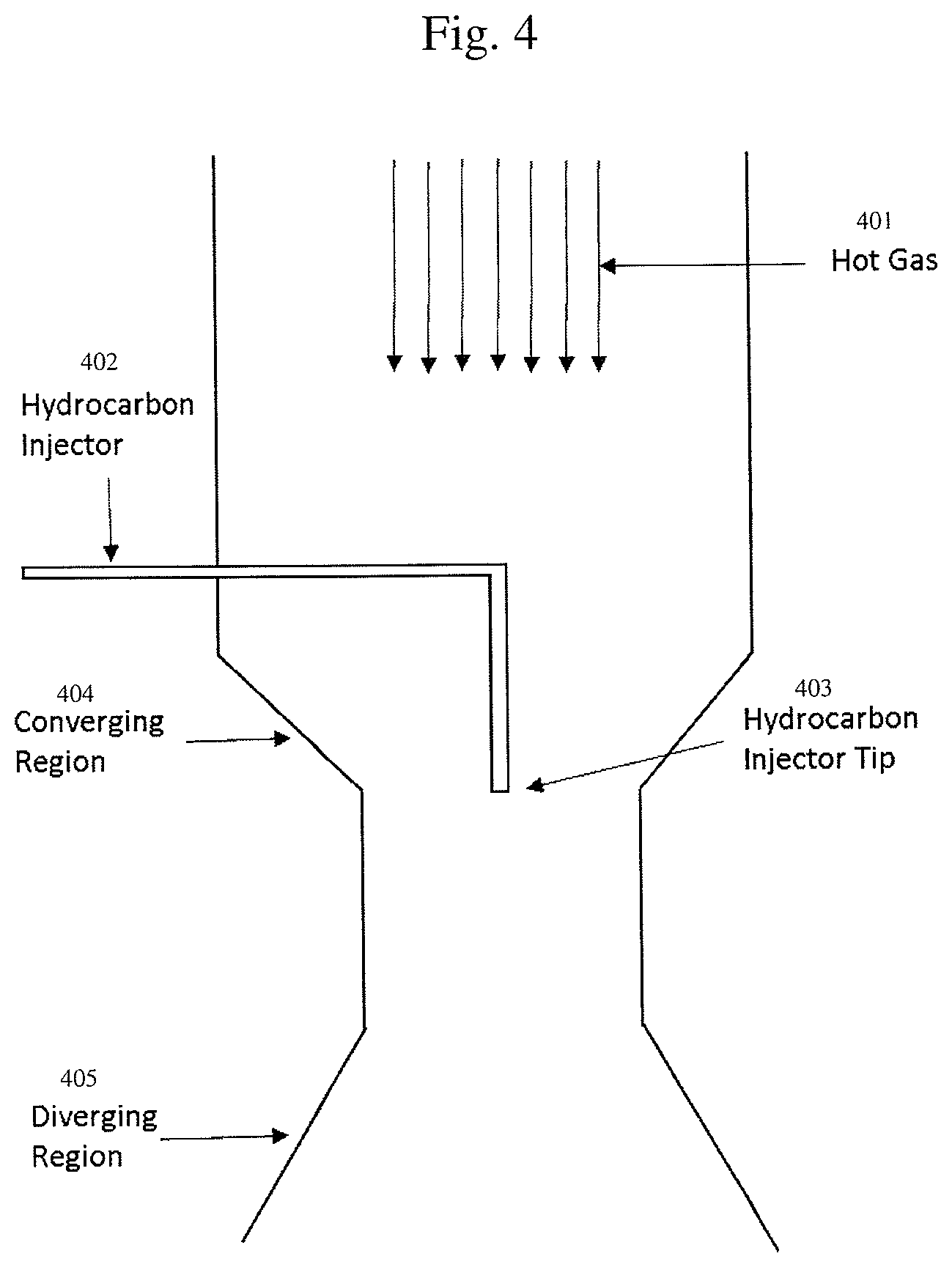
FIG. 4 shows another embodiment of an apparatus described herein. Hot gas is generated in the upper portion of the reactor either through the use of three or more AC electrodes, through the use of concentric DC electrodes as shown in FIGS. 2 and 3, or through the use of a resistive heater, more detail of which can be found in commonly assigned, U.S. Patent Application Ser. No. 62/209,017, High Temperature Heat Integration Method Of Making Carbon Black, the disclosure of which is herein incorporated by reference. The hot gas (401) is comprised of at least 50% hydrogen by volume that is at least 2400.degree. C. The hydrocarbon injector (402) can be water cooled and enters from the side of the reactor and then turns into an axial position in regard to hot gas flow. The hydrocarbon injector tip (403) can be one opening or a plurality of openings that can inject hydrocarbons in clockwise or counter clockwise flow patterns to optimize mixing. Optionally, there are converging regions (404) leading to a narrowing of the reactor and then diverging regions (405) downstream of the converging region.
FIGS. 5 and 6 are Transmission Electron Micrograph (TEM) images of typical carbon nanoparticle produced by the above processes. The surface active sites (501 and 601) are unique to these high temperature techniques and are not found in furnace carbon black samples. Only some representative surface active sites are labelled.
In its early years, carbon black was made from oil and tar via the lamp or thermal process. In the mid-19.sup.th century, the channel process which utilized the impingement of natural gas on hot iron channels became the main method of manufacture of carbon black. In the early 1940s, the furnace process came to the forefront which utilizes a heavy oil such as pyrolysis fuel oil (PFO) to manufacture carbon black in an oxygen lean combustion environment at carbon yields of approximately 40-50%.
Plasma based synthesis of carbon black utilizing natural gas has both cost and pollution reducing advantages over the furnace process. The process is clean, emitting near zero local CO.sub.2, and zero SO.sub.x--compared to multiple tons of CO.sub.2 for the furnace process, with tens of kilograms of NO.sub.x and SO.sub.x for every ton of carbon black produced. Although the plasma technique has been attempted many times throughout the last century, there have been no long term viable commercial production enterprises based on this process.
A one step process as described herein contains the reactants and products up until a degas step has been completed to remove the hydrogen that has been produced from the cracking of, for example, methane. Hydrogen is a highly combustible gas and must be separated from the as-produced carbon nanoparticles in order to manipulate the carbon nanoparticles. A degas is considered to be complete if the hydrogen level has been reduced to less than 20 percent by volume.
An oxygen free atmosphere is deemed to possess less than 5% oxygen by volume for the examples stated herein. Preferably, the oxygen free atmosphere is less than 3% or less than 1% oxygen.
In the past, plasma generator designs have not been able to meet the power, corrosion resistance, and continuous operation requirements to produce carbon black because of such things as the insufficient unit power of their basic components and the tendency of these components to decay when exposed to hydrogen plasma, resulting in lost reactor time, increased capital costs, and uneconomically produced carbon black, among other things. For more details concerning methods of heating hydrocarbons rapidly to form carbon nanoparticles and hydrogen please see the following commonly assigned, copending U.S. patent applications, the disclosures of which are herein incorporated by reference: Ser. No. 62/111,317, Carbon Black Combustible Gas Separation; Ser. No. 14/591,541, Use Of Feedstock In Carbon Black Plasma Process; Ser. No. 14/601,761, Plasma Gas Throat Assembly And Method; Ser. No. 14/601,793, Plasma Reactor; Ser. No. 62/198,431, DC Plasma Torch Electrical Power Design Method And Apparatus; Ser. No. 14/591,528, Integration Of Plasma And Hydrogen Process With Combined Cycle Power Plant, Simple Cycle Power Plant, And Steam Reformer; Ser. No. 62/202,498, Method Of Making Carbon Black; Ser. No. 14/610,299, Plasma Torch Design; Ser. No. 14/591,476, System For High Temperature Chemical Processing; Ser. No. 62/198,486, Method Of Making Carbon Black Including Thermal Transfer Gas; Ser. No. 62/111,341, Regenerative Cooling Method And Apparatus.
In addition, there have never been satisfactory rubber performance results of carbon nanoparticles produced in a plasma. When compounded into rubber, plasma based carbon nanoparticles have been substandard in performance when compared to furnace based carbon black. This is part of the reason that plasma produced carbon nanoparticles have never been adopted and mass produced. The processes and systems described herein can successfully generate quality carbon nanoparticles that can reinforce elastomer compounds.
Elastomer as defined herein refers to a class of polymers that are related to natural rubber that have both viscous and elastic components or viscoelasticity. Some example elastomers are natural rubber (NR), styrene butadiene rubber (SBR), polybutadiene, polyisobutylene, polyisoprene, nitrile rubber, ethylene propylene rubber (EPM), ethylene propylene diene rubber (EPDM), silicone rubber, fluoroelastomers, amongst other classes that can be found in "The Science and Technology of Rubber" (Mark, Erman, and Roland, Fourth Edition, Academic Press, .COPYRGT.2013).
Reinforcement of elastomer is defined as an increase in tensile strength, tear resistance, abrasion resistance, and modulus to increase beyond the values expected from simple particle-matrix theory. In other words, the carbon nanoparticle, be it carbon black or some other carbon nanoparticle, enables the stiffening of the gummy elastomer so that it can be more useful in applications such as tires, door seals, rubber hoses, etc.
A carbon nanoparticle is any particle which is 90% or greater carbon, has a surface area greater than 5 m.sup.2/g (square meters per gram), and the volume equivalent sphere possesses a diameter of less than 1 micron (displacement of liquid is equivalent to a 1 micron sphere or less per particle). This can be comprised of many different shapes including disks, bowls, cones, aggregated disks, few layer graphene (FLG), ellipsoidal, aggregated ellipsoidal, spheres, and aggregated spheres (e.g. carbon black), as non-limiting examples. The carbon nanoparticles can also comprise a plurality of these particle shapes. When using the definition of carbon nanoparticles, it is assumed that at least 90% of the particles in any given sample on a number basis fall within the confines of this definition.
Dibutyl phthalate (DBP) absorption measures the relative structure of carbon black by determining the amount of DBP a given mass of carbon black can absorb before reaching a specified viscous paste. Thermal blacks have the lowest DBP numbers (32-47 ml/100 g) (milliliters per gram) of any carbon black, indicating very little particle aggregation or structure. DBP is typically measured by following ASTM D2414-12. The nitrogen surface area (N2SA) and statistical thickness surface area (STSA) are measured via ASTM D6556-10.
Crystallinity of the carbon nanoparticle can be measured via X-Ray Crystal Diffractometry (XRD). Specifically for the measurements described herein, Cu K alpha radiation is used at a voltage of 40 kV (kilovolts) and a current of 44 mA (milliamps). The scan rate is 1.3 degrees/minute from 2 theta equal 12 to 90 degrees. The 002 peak of graphite is analyzed using the Scherrer equation to obtain Lc (lattice constant) and d002 (the lattice spacing of the 002 peak of graphite) values reported herein. Briefly, larger Lc values correspond to greater degree of crystallinity. Smaller lattice spacing (d002) values correspond to higher crystallinity or a more graphite like lattice structure. Larger lattice spacing (d002) of 0.36 nm or larger is indicative of turbostratic carbon which is common for carbon black samples produced via the furnace process. Elemental analysis is measured via devices manufactured by Leco and the results are given as percentage of the total sample.
Styrene butadiene rubber specimens were prepared according to ASTM D3191. ASTM D412 and ASTM D2240 were utilized to measure tensile properties and Shore A Hardness. Tangent delta was measured using TA Instruments RSA G2 device at a temperature range of -100 C to 100 C at a heating rate of 4 C/minute a strain of 0.5% and a frequency of 10 Hz.
TABLE-US-00001 TABLE 1 Physical Characteristics of Samples. N2SA STSA DBP Lc d002 Name (m2/g) (m2/g) (mL/100 g) (nm) (nm) S H N O N234 121 119 124 2.2 0.366 1.05 0.32 0.23 1.75 N234 125 130 118 2.9 0.358 0.70 0.03 0.08 0.2 @1200 N550 38.8 38.4 120 2.5 0.359 2.10 0.27 0.12 0.87 N762 26.2 25.6 65 2.6 0.358 1.57 0.26 0.08 0.52 M762 24.5 26.5 70 6.8 0.347 0.13 0.09 0.16 0.16 M550 45.6 48.8 135 6.9 0.346 0.15 0.09 0.2 0.11
TABLE-US-00002 TABLE 2 Elastomer composite performance values. Tensile Elongation Durometer 300% Strength at Break Shore Name (psi) (psi) (%) Hardness N234 3265 3507 326 75 N234 1235 3036 589 68 @1200C N762 1527 2870 496 63 M762 1547 2609 437 64 N550 2101 3161 450 58 M550 2136 3033 401 58
TABLE-US-00003 TABLE 3 Tan delta values for elastomer composites. Tan Tan Tan Delta Delta Delta Sample 60.degree. C. 40.degree. C. 0.degree. C. N762 0.1197 0.1329 0.1745 M762 0.1106 0.1226 0.1747 N550 0.1416 0.1553 0.2028 M550 0.1325 0.1456 0.1995
Samples of competitor grades of N234, N550, and N762 carbon blacks were obtained. These samples were made via the furnace process with a heavy oil. N234 was heat treated in an inert atmosphere at 1200.degree. C. and is labelled in the tables as "N234 @ 1200 C". M550 and M762 are designations given to Monolith carbon nanoparticles produced via mixing hot gas with natural gas as described herein.
Example 1
Manufacture of M762
Samples were manufactured using a setup similar to that shown in FIG. 3 where a hydrocarbon injector is inserted into the center of two concentric electrodes. The injector tip is 14 inches above the plane of the electrodes and the electrodes are operating at 650 kW. The plasma temperature was 2900.degree. C. and the fully mixed reaction temperature was 2100.degree. C. The hydrogen flow rate in the annulus between the electrodes was 90 Nm.sup.3/hr (normal cubic meters/hour) and the shield flow around the outside of the electrodes was 242 Nm.sup.3/hr. Natural gas was injected at a rate of 88 kg/hour. Yield of carbon nanoparticles based upon methane conversion rate was greater than 95%.
Example 2
Manufacture of M550
Samples were manufactured using a setup similar to that shown in FIG. 3 where a hydrocarbon injector is inserted into the center of two concentric electrodes. The injector tip is 14 inches above the plane of the electrodes and the electrodes are operating at 850 kW. The plasma temperature was 2900.degree. C. and the fully mixed reaction temperature was 2100.degree. C. The hydrogen flow rate in the annulus between the electrodes was 235 Nm3/hr (normal cubic meters/hour) and the shield flow around the outside of the electrodes was 192 Nm3/hr. Natural gas was injected at a rate of 103 kg/hour. Yield of carbon nanoparticles based upon methane conversion rate was greater than 94%.
Typical carbon black as currently made by the furnace process is made in a very similar fashion worldwide. Variation in hydrogen content, oxygen content, sulfur content and crystallinity is very minimal between different plants and different manufacturers. Grades are determined by the N2SA and by the DBP values. Only very minor differences can be determined due to differences in surface activity or crystallinity as all of the furnace blacks are very similar in these characteristics. Reference carbon black is a carbon black material as made in the furnace process that has values of N2SA and DBP within 20% of the carbon nanoparticles produced by the process described herein. In Table 1, the specific values of the reference furnace carbon black (labelled with "N" prefix) can be found and compared to the experimental grades that are labelled with an "M" prefix.
The importance of crystallinity and surface activity is paramount as can be seen in the examples from Tables 1 and 2. Through the heat treatment of N234 to only 1200.degree. C., the reinforcement capability of the carbon black has been completely eliminated. The hydrogen content is lower and the crystallinity is higher. Both of these factors point to lower performance of the carbon black as a reinforcing agent according to various literature sources (for example, "The Science and Technology of Rubber" cited above and "Carbon Black Elastomer Interaction" Rubber Chemistry and Technology, 1991, pages 19-39--the disclosures of which both are herein incorporated by reference).
Specifically, the modulus at 300% has decreased from 3265 psi to 1235 psi (pounds per square inch). The elongation at break has increased from 326% to 589% indicating that the rubber composite test specimen with the heat treated N234 behaves almost as though there were no carbon black filler present. The specimen is not stiff and behaves as the raw rubber gum would behave in terms of ability to stretch and force required to pull the specimen to 3 times the original length. The increased crystallinity, decreased d002, decreased hydrogen content all point to a less active surface, even though the N2SA and DBP are almost unchanged. The composites also typically contain about 0.5% to about 4% by weight sulfur.
For Monolith samples, even though the crystallinity is more than double that of the furnace black counterpart, the hydrogen content is one-third that of the furnace black counterpart and there is more than 10 times less sulfur present, the samples reinforce rubber quite well.
This is a surprising result that runs counterintuitive to current thought in carbon black reinforcement science. One possibility to these strong results is the existence of "fullerene-like" moieties in the carbon black produced in the process described herein. Fullerene-like structures may be formed by the introduction of defects into a graphene sheet. The defects may form one or more pentagonal, heptagonal or other kind of rings, or a combination thereof, to create one or more fullerene-like structures. The defects may introduce curvature to the graphene sheet. These types of surface active species are observed in FIGS. 5 and 6. For more information about fullerene like moieties, please see "The Impact of a Fullerene-Like Concept in Carbon Black Science", Carbon, 2002, pages 157-162the disclosure of which is incorporated by reference herein. In this paper it is proposed to radiate already manufactured carbon black with plasma gas, however, it was not conceived to be possible until now that fullerene-like moieties (referred to as "surface active sites" (501 and 601) in FIGS. 5 and 6) could be manufactured in one step from a hydrocarbon precursor.
Increasing tan delta at 0.degree. C. correlates to improved wet traction, while lowering tan delta at 60.degree. C. correlates to improved rolling resistance. Generally, conventional tread rubber compounds that optimize tan delta at one temperature negatively impact tan delta at the other temperature. It is therefore surprising that the M550 and M762 (given above in Table 3) show the same performance for tan delta at 0.degree. C. and improved performance at 60.degree. C. when compared to reference furnace carbon black. This should correspond to better rolling resistance in tire tread grades of carbon black while maintaining wet grip performance.
Thus, the scope of the invention shall include all modifications and variations that may fall within the scope of the attached claims. Other embodiments of the invention will be apparent to those skilled in the art from consideration of the specification and practice of the invention disclosed herein. It is intended that the specification and examples be considered as exemplary only, with a true scope and spirit of the invention being indicated by the following claims.
* * * * *
References
D00001
D00002
D00003
D00004
XML
uspto.report is an independent third-party trademark research tool that is not affiliated, endorsed, or sponsored by the United States Patent and Trademark Office (USPTO) or any other governmental organization. The information provided by uspto.report is based on publicly available data at the time of writing and is intended for informational purposes only.
While we strive to provide accurate and up-to-date information, we do not guarantee the accuracy, completeness, reliability, or suitability of the information displayed on this site. The use of this site is at your own risk. Any reliance you place on such information is therefore strictly at your own risk.
All official trademark data, including owner information, should be verified by visiting the official USPTO website at www.uspto.gov. This site is not intended to replace professional legal advice and should not be used as a substitute for consulting with a legal professional who is knowledgeable about trademark law.