Secondary Heat Addition To Particle Production Process And Apparatus
TAYLOR; Roscoe W. ; et al.
U.S. patent application number 16/097039 was filed with the patent office on 2019-04-04 for secondary heat addition to particle production process and apparatus. This patent application is currently assigned to MONOLITH MATERIALS, INC.. The applicant listed for this patent is MONOLITH MATERIALS, INC.. Invention is credited to Aaron S. HAMPTON, Robert J. HANSON, Alexander F. HOERMANN, Peter L. JOHNSON, Roscoe W. TAYLOR.
| Application Number | 20190100658 16/097039 |
| Document ID | / |
| Family ID | 60160134 |
| Filed Date | 2019-04-04 |


| United States Patent Application | 20190100658 |
| Kind Code | A1 |
| TAYLOR; Roscoe W. ; et al. | April 4, 2019 |
SECONDARY HEAT ADDITION TO PARTICLE PRODUCTION PROCESS AND APPARATUS
Abstract
Secondary heat may be added to a particle production process. The particles may be, for example, carbon particles. Among other things, the secondary heat addition may result in change in surface area of the carbon particle(s), change in structure of the carbon particle(s), reduced wall fouling, reduced energy consumption and/or increased throughput. Apparatus for performing the process is also described.
| Inventors: | TAYLOR; Roscoe W.; (Kingwood, TX) ; HOERMANN; Alexander F.; (Menlo Park, CA) ; JOHNSON; Peter L.; (Mountain View, CA) ; HANSON; Robert J.; (San Carlos, CA) ; HAMPTON; Aaron S.; (Los Gatos, CA) | ||||||||||
| Applicant: |
|
||||||||||
|---|---|---|---|---|---|---|---|---|---|---|---|
| Assignee: | MONOLITH MATERIALS, INC. Redwood City CA |
||||||||||
| Family ID: | 60160134 | ||||||||||
| Appl. No.: | 16/097039 | ||||||||||
| Filed: | April 28, 2017 | ||||||||||
| PCT Filed: | April 28, 2017 | ||||||||||
| PCT NO: | PCT/US17/30179 | ||||||||||
| 371 Date: | October 26, 2018 |
Related U.S. Patent Documents
| Application Number | Filing Date | Patent Number | ||
|---|---|---|---|---|
| 62329508 | Apr 29, 2016 | |||
| Current U.S. Class: | 1/1 |
| Current CPC Class: | C09C 1/485 20130101; C09C 1/48 20130101; B01J 19/26 20130101; C09C 1/54 20130101; B01J 6/008 20130101 |
| International Class: | C09C 1/54 20060101 C09C001/54; C09C 1/48 20060101 C09C001/48; B01J 6/00 20060101 B01J006/00 |
Claims
1. A process of producing carbon black, comprising creating a hot fluid, followed by injecting a carbon black producing feedstock into the hot fluid to crack the feedstock to form the carbon black, wherein heat is added to the process downstream of where the feedstock is injected.
2. The process of claim 1, wherein the added heat results in reduced wall fouling.
3. The process of claim 1, wherein the added heat results in increased throughput.
4. The process of claim 1, wherein the added heat results in higher carbon black yield.
5. The process of claim 1, wherein the resulting carbon black has increased surface area.
6. The process of claim 1, wherein the resulting carbon black has decreased surface area.
7. The process of claim 1, wherein the resulting carbon black has increased structure.
8. The process of claim 1, wherein the resulting carbon black has decreased structure.
9. The process of claim 1, wherein the resulting carbon black requires less energy to produce.
10. The process of claim 1, wherein the downstream heat is added at a temperature of at least about 1000.degree. C.
11. The process of claim 1, wherein the downstream heat is added at a temperature of at least about 1500.degree. C.
12. The process of claim 1, wherein the hot fluid is produced by a burner, an electrical heating system, or a plasma.
13. The process of claim 1, wherein the capacity of the reactor is greater than 3 kilotons/year, the hot fluid is a gas having a flow rate of at least about 500 Nm.sup.3/hr (normal cubic meter/hour) and the feedstock is a hydrocarbon having a flow rate of at least about 300 kg/hr (kilograms/hour).
14. The process of claim 1, wherein the feedstock is a hydrocarbon comprising methane, ethane, propane or mixtures thereof.
15. The process of claim 1, wherein the hot fluid is a plasma comprising greater than about 70% H.sub.2.
16. The process of claim 15, wherein the hot fluid additionally contains at least one or more of the gases of HCN, CH.sub.4, C.sub.2H.sub.4, C.sub.2H.sub.2, CO, benzene, or polyaromatic hydrocarbon, at a level of at least 1 part per million (ppm).
17. The process of claim 16, wherein the polyaromatic hydrocarbon comprises naphthalene, anthracene and/or their derivatives.
18. The process of claim 16, wherein the polyaromatic hydrocarbon comprises methyl naphthalene and/or methyl anthracene.
19. A carbon black generating apparatus, comprising: a heated fluid generating section; a carbon black producing feedstock injection section in fluid flow communication with the heated fluid generating section; and a carbon black forming feedstock cracking section in fluid flow communication with the feedstock injection section, wherein the carbon black forming feedstock cracking section comprises a supplemental heating section downstream of the feedstock injection section and produces (i) reduced wall fouling, (ii) increased or decreased surface area carbon blacks, (iii) increased or decreased structure carbon blacks, and/or (iv) higher throughput compared to in absence of the supplemental heating section.
20. The apparatus of claim 19, wherein the heated fluid generating section comprises a burner system, an electrical heating system, or a plasma generating system.
21. The apparatus of claim 19, wherein the supplemental heating section is capable of being heated to at least about 1000.degree. C.
22. The apparatus of claim 19, wherein the supplemental heating section is capable of being heated to at least about 1500.degree. C.
23. The apparatus of claim 19, wherein the supplemental heating section comprises a heat conductive wall.
24. A process of producing carbon particles, comprising: providing a hot fluid in a reactor; injecting a feedstock into the hot fluid to crack the feedstock, wherein the feedstock generates the carbon particles upon cracking; and adding external heat to the process downstream of where the hot fluid is provided.
25. The process of claim 24, wherein the particles comprise carbon black.
26. The process of claim 24, further comprising adding the external heat to the process where the feedstock is injected.
27. The process of claim 24, further comprising adding the external heat to the process downstream of where the feedstock is injected.
28. The process of claim 24, further comprising adding the external heat by wall heating.
29. The process of claim 24, wherein providing the hot fluid comprises combusting a combustible mixture.
30. The process of claim 24, wherein providing the hot fluid comprises heating with electrical energy.
31. The process of claim 24, further comprising adding the external heat to the process to control the cracking of the feedstock.
32. The process of claim 31, further comprising adding the external heat to the process to control quality of the carbon particles.
33. The process of claim 31, further comprising adding the external heat to the process to control wall fouling.
34. A process of producing carbon particles, comprising: generating a hot fluid in a reactor; mixing a feedstock into the hot fluid to crack the feedstock, wherein the feedstock generates the carbon particles upon cracking; and adding external heat to the process during or after the mixing, thereby increasing a process temperature during or after the mixing (i) without increasing an amount of the hot fluid that is generated and (ii) without increasing a temperature of the hot fluid that is generated.
35. The process of claim 34, wherein the particles comprise carbon black.
36. The process of claim 34, further comprising adding the external heat to the process where the feedstock is injected.
37. The process of claim 34, further comprising adding the external heat to the process downstream of where the feedstock is injected.
38. The process of claim 34, further comprising adding the external heat by wall heating.
39. The process of claim 34, wherein providing the hot fluid comprises combusting a combustible mixture.
40. The process of claim 34, wherein providing the hot fluid comprises heating with electrical energy.
Description
CROSS-REFERENCE
[0001] This application claims the benefit of U.S. Provisional Application No. 62/329,508, filed Apr. 29, 2016, which is entirely incorporated herein by reference.
BACKGROUND
[0002] Particles are used in many household and industrial applications. The particles may be produced by various chemical processes. Performance and energy supply associated with such chemical processes has evolved over time.
SUMMARY
[0003] The present disclosure recognizes a need for more efficient and effective processes to produce particles, such as, for example, carbon particles. Also recognized herein is a need to increase speed of production, increase yields, reduce manufacturing equipment wear characteristics, etc. The present disclosure may provide, for example, improved processes for converting hydrocarbon-containing materials into carbon particles.
[0004] The present disclosure provides, for example, a process of producing carbon black, comprising creating a hot fluid, followed by injecting a carbon black producing feedstock into the hot fluid to crack the feedstock to form the carbon black, wherein heat is added to the process downstream of where the feedstock is injected. The added heat may result in reduced wall fouling. The added heat may result in increased throughput. The added heat may result in higher carbon black yield. The resulting carbon black may have increased surface area. The resulting carbon black may have decreased surface area. The resulting carbon black may have increased structure. The resulting carbon black may have decreased structure. The resulting carbon black may require less energy to produce. The downstream heat may be added at a temperature of at least about 1000.degree. C. The downstream heat may be added at a temperature of at least about 1500.degree. C. The hot fluid may be produced by a burner, an electrical heating system, or a plasma. The capacity of the reactor may be greater than 3 kilotons/year, the hot fluid may be a gas having a flow rate of at least about 500 Nm.sup.3/hr (normal cubic meter/hour) and the feedstock may be a hydrocarbon having a flow rate of at least about 300 kg/hr (kilograms/hour). The feedstock may be a hydrocarbon comprising methane, ethane, propane or mixtures thereof. The hot fluid may be a plasma comprising greater than about 70% H.sub.2. The hot fluid may additionally contain at least one or more of the gases of HCN, CH.sub.4, C.sub.2H.sub.4, C.sub.2H.sub.2, CO, benzene, or polyaromatic hydrocarbon, at a level of at least 1 part per million (ppm). The polyaromatic hydrocarbon may comprise naphthalene, anthracene and/or their derivatives. The polyaromatic hydrocarbon may comprise methyl naphthalene and/or methyl anthracene.
[0005] The present disclosure also provides, for example, a carbon black generating apparatus, comprising: a heated fluid generating section; a carbon black producing feedstock injection section in fluid flow communication with the heated fluid generating section; and a carbon black forming feedstock cracking section in fluid flow communication with the feedstock injection section, wherein the carbon black forming feedstock cracking section comprises a supplemental heating section downstream of the feedstock injection section and produces (i) reduced wall fouling, (ii) increased or decreased surface area carbon blacks, (iii) increased or decreased structure carbon blacks, and/or (iv) higher throughput compared to in absence of the supplemental heating section. The heated fluid generating section may comprise a burner system, an electrical heating system, or a plasma generating system. The supplemental heating section may be capable of being heated to at least about 1000.degree. C. The supplemental heating section may be capable of being heated to at least about 1500.degree. C. The supplemental heating section may comprise a heat conductive wall.
[0006] The present disclosure also provides, for example, a process of producing carbon particles, comprising: providing a hot fluid in a reactor; injecting a feedstock into the hot fluid to crack the feedstock, wherein the feedstock generates the carbon particles upon cracking; and adding external heat to the process downstream of where the hot fluid is provided. The particles may comprise carbon black. The process may further comprise adding the external heat to the process where the feedstock is injected. The process may further comprise adding the external heat to the process downstream of where the feedstock is injected. The process may further comprise adding the external heat by wall heating. Providing the hot fluid may comprise combusting a combustible mixture. Providing the hot fluid may comprise heating with electrical energy. The process may further comprise adding the external heat to the process to control the cracking of the feedstock. The process may further comprise adding the external heat to the process to control quality of the carbon particles. The process may further comprise adding the external heat to the process to control wall fouling.
[0007] The present disclosure also provides, for example, a process of producing carbon particles, comprising: generating a hot fluid in a reactor; mixing a feedstock into the hot fluid to crack the feedstock, wherein the feedstock generates the carbon particles upon cracking; and adding external heat to the process during or after the mixing, thereby increasing a process temperature during or after the mixing (i) without increasing an amount of the hot fluid that is generated and (ii) without increasing a temperature of the hot fluid that is generated. The particles may comprise carbon black. The process may further comprise adding the external heat to the process where the feedstock is injected. The process may further comprise adding the external heat to the process downstream of where the feedstock is injected. The process may further comprise adding the external heat by wall heating. Providing the hot fluid may comprise combusting a combustible mixture. Providing the hot fluid may comprise heating with electrical energy.
[0008] These and additional embodiments are further described below.
BRIEF DESCRIPTION OF DRAWINGS
[0009] The novel features of the invention are set forth with particularity in the appended claims. A better understanding of the features and advantages of the present invention will be obtained by reference to the following detailed description that sets forth illustrative embodiments, in which the principles of the invention are utilized, and the accompanying drawings or figures (also "FIG." and "FIGS." herein), of which:
[0010] FIG. 1 shows a schematic representation of an example of a reactor/apparatus.
[0011] FIG. 2 shows a schematic representation of another example of a reactor/apparatus; and
[0012] FIG. 3 shows a schematic representation of another example of a reactor/apparatus.
DETAILED DESCRIPTION
[0013] The particulars shown herein are by way of example and for purposes of illustrative discussion of the various embodiments of the present invention only and are presented in the cause of providing what is believed to be the most useful and readily understood description of the principles and conceptual aspects of the invention. In this regard, no attempt is made to show details of the invention in more detail than is necessary for a fundamental understanding of the invention, the description making apparent to those skilled in the art how the several forms of the invention may be embodied in practice.
[0014] The present invention will now be described by reference to more detailed embodiments. This invention may, however, be embodied in different forms and should not be construed as limited to the embodiments set forth herein. Rather, these embodiments are provided so that this disclosure will be thorough and complete, and will fully convey the scope of the invention to those skilled in the art.
[0015] Unless otherwise defined, all technical and scientific terms used herein have the same meaning as commonly understood by one of ordinary skill in the art to which this invention belongs. The terminology used in the description of the invention herein is for describing particular embodiments only and is not intended to be limiting of the invention. As used in the description of the invention and the appended claims, the singular forms "a," "an," and "the" are intended to include the plural forms as well, unless the context clearly indicates otherwise. All publications, patent applications, patents, and other references mentioned herein are expressly incorporated by reference in their entirety.
[0016] Unless otherwise indicated, all numbers expressing quantities of ingredients, reaction conditions, and so forth used in the specification and claims are to be understood as being modified in all instances by the term "about." Accordingly, unless indicated to the contrary, the numerical parameters set forth in the following specification and attached claims are approximations that may vary depending upon the desired properties sought to be obtained by the present invention. At the very least, and not as an attempt to limit the application of the doctrine of equivalents to the scope of the claims, each numerical parameter should be construed in light of the number of significant digits and ordinary rounding approaches.
[0017] Notwithstanding that the numerical ranges and parameters setting forth the broad scope of the invention are approximations, the numerical values set forth in the specific examples are reported as precisely as possible. Any numerical value, however, inherently contains certain errors necessarily resulting from the standard deviation found in their respective testing measurements. Every numerical range given throughout this specification will include every narrower numerical range that falls within such broader numerical range, as if such narrower numerical ranges were all expressly written herein.
[0018] Additional advantages of the invention will be set forth in part in the description which follows, and in part will be obvious from the description, or may be learned by practice of the invention. It is to be understood that both the foregoing general description and the following detailed description are exemplary and explanatory only and are not restrictive of the invention, as claimed. It shall be understood that different aspects of the invention can be appreciated individually, collectively, or in combination with each other.
[0019] The present disclosure provides systems and methods for affecting chemical changes. Affecting such chemical changes may include making particles (e.g., carbon particles, such as, for example, carbon black) using the systems and methods of the present disclosure. While such particles may be described herein primarily in terms of or in the context of carbon particles, the particles of the present disclosure may include other types of particles. Carbon particles may comprise fine particles. A fine particle may be a particle that has at least one dimension that is less than 100 nm (nanometers). A fine particle may be an aggregate that is smaller than about 5 microns average size when measured in the largest dimension via scanning or tunneling electron microscopy. The carbon particles may comprise spherical and/or ellipsoidal fine carbon particles. Spherical or ellipsoidal particles may mean singular particles and may also mean a plurality of particles that are stuck together in a fashion analogous to that of a bunch of grapes or aciniform. Carbon black may be an example of this type of fine carbon particle. The carbon particles may comprise few layer graphenes (FLG), which may comprise particles that possess two or more layers of graphene and have a shape that is best described as flat or substantially flat. The carbon particles may be substantially in disk form. The carbon particles may comprise carbonaceous pigment. A carbon particle may include a carbon nanoparticle. A carbon nanoparticle may include, for example, any particle which is 90% or greater carbon, has a surface area greater than 5 m.sup.2/g (square meters per gram), and the volume equivalent sphere possesses a diameter of less than 1 micron (displacement of liquid is equivalent to a 1 micron sphere or less per particle). This may comprise many different shapes including disks, bowls, cones, aggregated disks, few layer graphene (FLG), ellipsoidal, aggregated ellipsoidal, spheres, and aggregated spheres (e.g. carbon black), as non-limiting examples. The carbon nanoparticles may also comprise a plurality of these particle shapes. At least 90% of the particles in any given sample of carbon nanoparticles on a number basis may fall within the confines of this definition of carbon nanoparticles.
[0020] A particle production process (e.g., carbon black production), may use a two stage process. In the first stage, a hot fluid may be created, such as in a burner or other means, after which feedstock may be injected into the process. Residual oxidants from the first stage may then combust a portion of the feedstock when a combustion based process is in use, followed by, or with simultaneous cracking of, the feedstock to form carbon black. The aim may be to rapidly heat the feedstock by mixing it into the first stage gases, whereupon an endothermic cracking process may result in a fall in temperature to a final fully mixed and reacted bulk temperature. The amount of heat available for cracking may effectively limit the amount of feedstock that can be added for a given reacted temperature. Adding more feedstock may then reduce the reaction temperature (e.g., and so the surface area and/or other quality measures), changing the quality of the carbon black produced. Equipment may limit the maximum amount of heat available according to the temperature limits of the burner and/or heating equipment. These limitations may result from temperature limits of materials used in these regions, heat loss rate from wasting energy (and also increasing cost) when using cooling to keep equipment within its temperature constraints, or from equipment temperatures, or cooling loads, produced where the injection of the feedstock causes increased heat fluxes from additional combustion or radiating particles. Providing substantially no heat from the walls may (e.g., also) limit the process to the temperature limits of the combustion, rather than adding heat where the process is cooler. These approaches may produce, for example, less product or at a lower surface area than when used in combination with wall heating as described herein.
[0021] The processes and equipment (e.g., apparatuses) described herein may add external heat to a particle reactor downstream of a region or section where the hot fluid is generated or created (also "heated fluid generating section" herein). The processes and equipment (e.g., apparatuses) described herein may add external secondary heat to a particle reactor downstream of primary heat addition (e.g., downstream of where the hot fluid is generated or created). The processes and equipment (e.g., apparatuses) described herein may add heat to a particle reactor (e.g., carbon black reactor) at or downstream of feedstock injection (e.g., at or adjacent to the feedstock injection location, or downstream of the feedstock injection location). The processes and equipment (e.g., apparatuses) described herein may add heat to one or more particle formation regions or zones of a particle reactor (also "reactor" and "reactor apparatus" herein). Such heat addition may increase temperature of the fluid and/or particles, and/or in one or more regions or zones described herein by at least about 0.5%, 1%, 2%, 5%, 10%, 15%, 20%, 25%, 30%, 40%, 45%, 50%, 75%, 90%, 100%, 150%, 200%, 250%, 300%, 350%, 400%, 450% or 500% compared with the temperature in the absence of such heat addition (e.g., at otherwise equivalent conditions). Secondary heat addition described herein may add heat to the fluid and/or particles, and/or to one or more regions or zones described herein via convection, radiation or a combination thereof. The temperature may be increased without further dilution of the feedstock by hot gas (e.g., hot thermal transfer gas). For example, the temperature may be increased without additional dilution with plasma gas. The process may instead include generating a hot fluid, mixing the feedstock into the hot fluid to crack the feedstock, and adding external heat to the process (e.g., during or after the mixing). The addition of the external heat may allow the process temperature to be increased without increasing an amount of the hot fluid that is generated (without thereby further diluting the feedstock), and/or without increasing a temperature of the hot fluid that is generated.
[0022] The processes and equipment described herein may add secondary heat to the process where the process is cooler. The secondary heat may be provided (e.g., sequentially and/or simultaneously) in/to greater than or equal to 1, 2, 3, 4, 5, 6, 7, 8, 9, 10, 12, 14, 16, 18, 20, 25, 30, 35, 40, 45, 50, 75 or 100 regions or zones of a reactor. Alternatively, or in addition, the secondary heat may be provided (e.g., sequentially and/or simultaneously) in/to less than or equal to 100, 75, 50, 45, 40, 35, 30, 25, 20, 18, 16, 14, 12, 10, 9, 8, 7, 6, 5, 4, 3 or 2 regions or zones of a reactor. Wall heating location(s) may correspond to the location(s) of at least a portion of these regions or zones. The heat may be added directly at the wall of a region or zone. The added heat may be transferred to the fluid and/or particles by convection and/or radiation. The added heat may be transferred to the fluid and/or particles adjacent to the wall, and/or transferred to the fluid and/or particles in a region and/or zone farther away from the location of the heat addition (e.g., by radiation). In some examples (e.g., if there is recirculating flow in the reactor), heat may be added at the reactor wall at a stream-wise location before (e.g., above) one or more recirculation points (e.g., above a recirculation point), at a stream-wise location after (e.g., below) one or more recirculation points (e.g., below a recirculation point), at a stream-wise location between recirculation points, or any combination thereof (e.g., see FIG. 1). A recirculation point may refer to, for example, a detachment or separation point, or a reattachment point.
[0023] The added heat may be transferred/added to fluid and/or particles at a given time (or range of times) after injection. The time after injection may refer to the time elapsed from when the feedstock fluid is injected into the reactor (e.g., measured from the time point when the feedstock exits the injector and/or enters the reactor). The time after injection may refer to the time after injection of a carbon-containing fluid and/or particles. The heat may be added to the fluid and/or particles at a given time/location corresponding to a given fluid/particle time (or range of times) after injection. Such times after injection (e.g., individual and/or average particle times after injection) may be, for example, greater than or equal to about 0, 0.1 millisecond (ms), 0.5 ms, 1 ms, 2 ms, 3 ms, 4 ms, 5 ms, 6 ms, 7 ms, 8 ms, 9 ms, 10 ms, 20 ms, 30 ms, 40 ms, 50 ms, 60 ms, 70 ms, 80 ms, 90 ms, 100 ms, 200 ms, 300 ms, 400 ms, 500 ms, 600 ms, 700 ms, 800 ms, 900 ms, 1 second (s), 1.2 s, 1.4 s, 1.6 s, 1.8 s, 2 s, 2.2 s, 2.4 s, 2.6 s, 2.8 s, 3 s, 3.2 s, 3.4 s, 3.6 s, 3.8 s, 4 s, 4.2 s, 4.4 s, 4.6 s, 4.8 s or 5 s. Alternatively, or in addition, such times after injection (e.g., individual and/or average particle times after injection) may be, for example, less than or equal to about 5 s, 4.8 s, 4.6 s, 4.4 s, 4.2 s, 4 s, 3.8 s, 3.6 s, 3.4 s, 3.2 s, 3 s, 2.8 s, 2.6 s, 2.4 s, 2.2 s, 2 s, 1.8 s, 1.6 s, 1.4 s, 1.2 s, 1 s, 900 ms, 800 ms, 700 ms, 600 ms, 500 ms, 400 ms, 300 ms, 200 ms, 100 ms, 90 ms, 80 ms, 70 ms, 60 ms, 50 ms, 40 ms, 30 ms, 20 ms, 10 ms, 9 ms, 8 ms, 7 ms, 6 ms, 5 ms, 4 ms, 3 ms, 2 ms, 1 ms, 0.5 ms or 0.1 ms. Various subranges may be defined (e.g., bound) by such times. A given (time) range may correspond to one or more heat additions.
[0024] The processes and equipment (e.g., apparatuses) described herein may add heat to a particle reactor (e.g., carbon black reactor), for example, in a recirculation zone. By heating the reactor walls, the fluid and particles that recirculate past or close to the heated walls may increase in temperature. When this higher temperature material mixes into the particle forming region(s) (e.g., carbon black forming region(s)) of the process, these region(s) may increase in temperature. When this higher temperature material mixes into the particle forming region(s) (e.g., carbon black forming region(s)) of the process, these region(s) may increase in temperature, increasing temperature of the forming particles (e.g., and so, in some cases, produce a higher surface area), enabling an increase in the feedstock flow (e.g., and so enable a higher throughput), or a combination thereof. The heating of the walls may (e.g., also) add heat to the particle formation region (also "particle forming region" herein) through radiative heat transfer and provide similar benefits, or even enhanced benefits such as, for example, higher surface area for the same energy input (e.g., at least about 0.5%, 1%, 2%, 5%, 10%, 15%, 20%, 25%, 30%, 40%, 45%, 50%, 75%, 100%, 150%, 200%, 250%, 300%, 350%, 400%, 450% or 500% higher surface area for the same energy input). This higher surface area (and/or enhanced control of surface area as described in greater detail elsewhere herein) may allow production of more grades of carbon particles (e.g., carbon black). A process with increased time at temperature may (e.g., also) increase conversion and/or reduce product extract (e.g., polycyclic aromatic hydrocarbons (PAHs), materials that did not completely react). A higher throughput may (e.g., also) significantly reduce the size (and capital expense) of downstream equipment (e.g., in a recycle loop). Such process equipment may include, for example, fluid heating system, reactor, product cooler, main unit filter, blower/compressor and/or gas cleanup membrane system (e.g., configured for a given production rate). See, for example, commonly assigned, co-pending Int. Pat. Pub. No. WO 2016/126599 ("CARBON BLACK GENERATING SYSTEM"), which is entirely incorporated herein by reference. The hotter walls may (e.g., also) reduce reactor wall fouling (e.g., by creating a thermophoretic force on the particles, driving them away from the walls), as described in greater detail elsewhere herein.
[0025] The processes described herein may increase the heat available for cracking by adding heat to the process/equipment in the cooler region downstream of the injected feedstock by heating the reactor walls. These walls may then transfer heat to the gases convectively and/or directly to the forming particles via radiation from the walls and/or from already formed recirculating particles. In some examples (e.g., in the case of a generally plug flow situation), heat may be added as soon as the cracking lowers the temperature below that of the limits of the materials used to transfer the heat, but upstream of when the particle formation completes. In some examples (e.g., in the case of a system with recirculation (e.g., see FIG. 1), the heat added may (e.g., also) be added to (e.g., go into) the fully formed product and reacted materials, increasing their temperatures (e.g., so that when they mix into the feedstock and/or particles forming from the feedstock, the resulting local mixture temperature may increase or decline more slowly). Such heat addition may result in production of, for example, carbon particles with higher surface area (e.g., a higher surface area carbon black) and/or a higher rate of production with the same equipment (carbon in to carbon out yield). In some examples, carbon particles with higher surface area (e.g., a higher surface area carbon black) and/or a higher rate of production with the same equipment (carbon in to carbon out yield) may be achieved for the same energy input (e.g., more carbon for the same energy input).
[0026] A process of the present disclosure (e.g., a plasma process used with a carbon-containing feedstock such as, for example, natural gas) may be an endothermic process. The carbon-containing feedstock (e.g., natural gas) may decompose to carbon and one or more other decomposition products (e.g., hydrogen). The decomposition may require energy input. Such a process (e.g., the plasma process) may not take advantage of an exothermic reaction (e.g., utilizing a combustion flame such as, for example, using oxygen to combust methane, other hydrocarbon or hydrocarbon feedstock before injection of the hydrocarbon feedstock), and heat may be depleted from the walls of the reactor without compensation (e.g., without compensation by additional combustion). Adding heat to the walls may be beneficial (e.g., may provide additional benefits in such instances) due to this depletion process.
[0027] The reactions of carbon particle forming systems (e.g., carbon black forming systems) may be contained in a reactor that separates the hot (e.g., greater than about 1,000.degree. C.) materials from the surrounding environment. Due to heat losses to cooling water and/or to the surrounding environment, there may be a heat flux out of the reactor, and the walls may be cooler than the contained materials. This may create a thermophoretic force on the particles. The thermophoretic force may drive the particles to the walls of the reactor, and potentially deposit the particles on the walls of the reactor. These deposits may turn (e.g., in time) into coke that may then slough off and contaminate the product in the form of grit (e.g., see ASTM D1514 water wash grit test). The coke may (e.g., also) reduce the reactor volume (e.g., to the point of impacting product quality). Secondary heat addition may be used to maintain or achieve a given product quality (e.g., product quality that meets required quality specifications such as, for example, extract according to ASTM D1618 (e.g., ASTM D1618-99)). For example, secondary heat addition may be used to maintain extract below a given level. Heating the walls may create a driving force away from the wall and so decrease, limit or even eliminate such wall deposits (also "wall fouling" herein).
[0028] Wall heating may (e.g., also) reduce the time and/or cost to heat up the system. Since wall heating may not depend on flow, it may (e.g., also) enable warm-up of the reactor when components that are upstream or downstream of the reactor are not running and/or while they are serviced (e.g., when they are being worked on). Such warm-up may (e.g., also) consume less energy when compared to heating the reactor with a hot gas flow. In a system heated with hot gas flow, the gas may leave the system at best in thermal equilibrium with the warming walls, and the heat contained in the gas may either be lost or in need of recovery. A hot wall reactor as described herein may have no gas flow and so the only energy lost may be in some instances be that through the reactor's insulation, heat that may also be lost when using a hot gas heating system.
[0029] The processes and equipment described herein may be advantageously used (e.g., may work particularly well) with high temperature materials (e.g., especially those that conduct heat well), and/or when higher temperatures (e.g., greater than about 1500.degree. C.) are employed. High conductivity (e.g., high thermal conductivity) may (e.g., also) enable better distribution of the heat from the heater to other parts of the process and equipment (e.g., via heat conduction). Even greater effects on quality may be achieved, for example, by maintaining (e.g., due to the ability to maintain) even hotter wall temperatures close to the feedstock injector by conducting heat from other parts of the reactor (e.g., from downstream parts of the reactor) rather than just heating a given body of fluid and/or particles (e.g., rather than just heating the recirculating materials).
[0030] The processes of the present disclosure may include creating a hot fluid (e.g., a thermal transfer gas), followed by injecting a feedstock (e.g., a hydrocarbon feedstock) into the hot fluid (e.g., to crack the feedstock to form carbon particles such as, for example, carbon black). The processes of the present disclosure may include creating a hot fluid (e.g., hot thermal transfer gas), and mixing the hot fluid with a hydrocarbon feedstock to generate the carbon particles (e.g., carbon black). The hot fluid may be produced, for example, by a burner or with electrical energy (e.g., from a DC or AC source). The hot fluid may be produced, for example, by a burner, an electrical heating system or a plasma. The hot fluid (also "heated fluid" herein) may be produced in a heated fluid generating section. The heated fluid generating section may comprise, for example, a burner system, an electrical heating system or a plasma generating system. Such reactors may be, for example, as described in relation to the schematic representations of examples of reactors in FIGS. 1, 2 and 3. Secondary, external heat may be added to the process downstream of where the hot fluid is created. Heat (e.g., secondary, external heat) may be added to the process at the point where the feedstock is injected. Heat (e.g., secondary, external heat) may be added to the process downstream of where the feedstock is injected.
[0031] The hydrocarbon feedstock may include any chemical with formula C.sub.nH.sub.x or C.sub.nH.sub.xO.sub.y, where n is an integer; x is between (i) 1 and 2n+2 or (ii) less than 1 for fuels such as coal, coal tar, pyrolysis fuel oils, and the like; and y is between 0 and n. The hydrocarbon feedstock may include, for example, simple hydrocarbons (e.g., methane, ethane, propane, butane, etc.), aromatic feedstocks (e.g., benzene, toluene, methyl naphthalene, pyrolysis fuel oil, coal tar, coal, heavy oil, oil, bio-oil, bio-diesel, other biologically derived hydrocarbons, and the like), unsaturated hydrocarbons (e.g., ethylene, acetylene, butadiene, styrene, and the like), oxygenated hydrocarbons (e.g., ethanol, methanol, propanol, phenol, ketones, ethers, esters, and the like), or any combination thereof. These examples are provided as non-limiting examples of acceptable hydrocarbon feedstocks which may further be combined and/or mixed with other components for manufacture. A hydrocarbon feedstock may refer to a feedstock in which the majority of the feedstock (e.g., more than about 50% by weight) is hydrocarbon in nature. The reactive hydrocarbon feedstock may comprise at least about 70% by weight methane, ethane, propane or mixtures thereof. The hydrocarbon feedstock may be natural gas. The hydrocarbon may be methane, ethane, or propane or mixtures thereof.
[0032] In some examples, the heated fluid may comprise combustion gases. In some examples, the heated fluid may be produced by heating a thermal transfer gas. The thermal transfer gas may comprise at least about 60% hydrogen up to about 100% hydrogen (by volume) and may further comprise up to about 30% nitrogen, up to about 30% CO, up to about 30% CH.sub.4, up to about 10% HCN, up to about 30% C.sub.2H.sub.2, and up to about 30% Ar. For example, the thermal transfer gas may be greater than about 60% hydrogen. Additionally, the thermal transfer gas may also comprise polycyclic aromatic hydrocarbons such as anthracene, naphthalene, coronene, pyrene, chrysene, fluorene, and the like. In addition, the thermal transfer gas may have benzene and toluene or similar monoaromatic hydrocarbon components present. For example, the thermal transfer gas may comprise greater than or equal to about 90% hydrogen, and about 0.2% nitrogen, about 1.0% CO, about 1.1% CH.sub.4, about 0.1% HCN and about 0.1% C.sub.2H.sub.2. The thermal transfer gas may comprise greater than or equal to about 80% hydrogen and the remainder may comprise some mixture of the aforementioned gases, polycyclic aromatic hydrocarbons, monoaromatic hydrocarbons and other components. Thermal transfer gas such as oxygen, nitrogen, argon, helium, air, hydrogen, carbon monoxide, hydrocarbon (e.g. methane, ethane, unsaturated) etc. (used alone or in mixtures of two or more) may be used. The thermal transfer gas may comprise greater than or equal to about 50% hydrogen by volume. The thermal transfer gas may comprise, for example, oxygen, nitrogen, argon, helium, air, hydrogen, hydrocarbon (e.g. methane, ethane) etc. (used alone or in mixtures of two or more). The thermal transfer gas may comprise greater than about 70% H.sub.2 by volume and may include at least one or more of the gases HCN, CH.sub.4, C.sub.2H.sub.4, C.sub.2H.sub.2, CO, benzene or polyaromatic hydrocarbon (e.g., naphthalene (and/or its derivative(s)), anthracene (and/or its derivative(s)), methyl naphthalene and/or methyl anthracene) at a level of at least about 1 ppm. The thermal transfer gas may have at least a subset of such compositions before, during and/or after heating. The thermal transfer gas may in some instances be heated in an oxygen-free environment. The carbon particles may in some instances be produced (e.g., manufactured) in an oxygen-free atmosphere. An oxygen-free atmosphere may comprise, for example, less than about 5% oxygen by volume, less than about 3% oxygen (e.g., by volume), or less than about 1% oxygen (e.g., by volume).
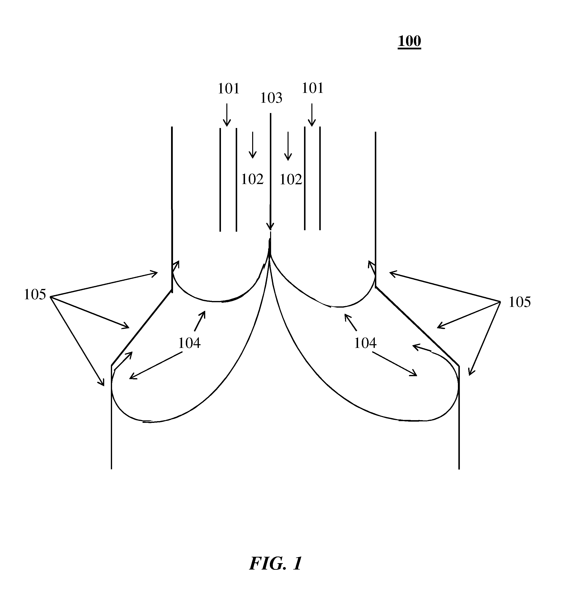
[0033] FIG. 1 shows a schematic representation of an example of an apparatus (and process) 100. A thermal transfer gas (e.g., plasma gas) such as, for example, oxygen, nitrogen, argon, helium, air, hydrogen, hydrocarbon (e.g., methane, ethane) etc. (used alone or in mixtures of two or more) may be injected into a thermal generation (e.g., plasma forming) zone or region. The thermal generation zone or region may comprise or contain, for example, plasma forming electrodes (e.g., made of copper, tungsten, graphite, molybdenum, silver, etc.). The thus-formed hot gas (e.g., the thus-formed plasma) may then enter into a reaction zone or region where it may react/interact with a carbon-containing feedstock to generate a carbon particle (e.g., carbon black) product.
[0034] The thermal transfer gas (e.g., plasma gas) may be introduced into a thermal generator (e.g., a plasma generating torch) through channels 101 and 102. The carbon-containing feedstock may be introduced, for example, through channel 103. Added heat (e.g., secondary heat) may be supplied to reactor walls at 105, resulting, for example, in a repelling of recycle particle flow 104 (shown in FIG. 1 in an unheated state). The hotter the walls, the more the recycle particles may be repelled from the reactor walls (e.g., as opposed to otherwise being attracted to the cooler walls). This may result, among other things, in putting/getting more particles through the process (e.g., higher carbon yield), and/or fewer particles attaching to the reactor wall surfaces 105.
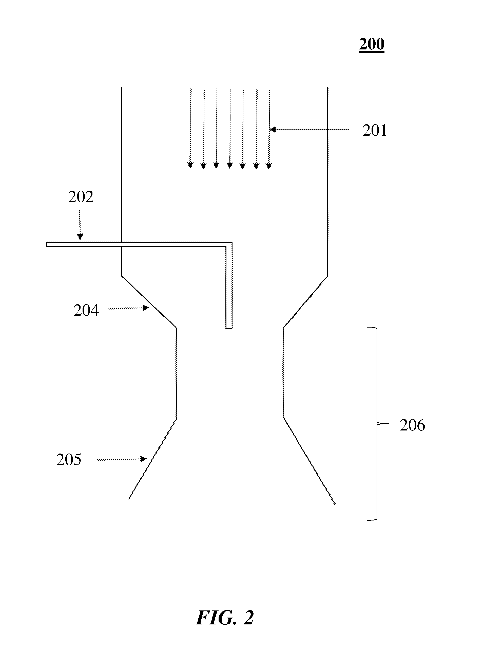
[0035] FIG. 2 shows a cross-section of another example of (a part of) a reactor 200. In this example, hot thermal transfer gas 201 may be generated in an upper portion of the reactor through the use of three or more AC electrodes, through the use of concentric DC electrodes (e.g., as shown in FIGS. 3 and 4), or through the use of a resistive or inductive heater. The hot thermal transfer gas may comprise, for example, at least about 50% hydrogen by volume that may be at least about 2,400.degree. C. The hydrocarbon may be injected through an injector 202 that may enter from the side of the reactor and then turn into an axial position with respect to the thermal transfer gas (hot gas) flow. The reactor may comprise converging region(s) 204. The converging region(s) 204 may lead to a narrowing of the reactor. The converging region(s) 204 may lead to a narrowing of the reactor and then diverging region(s) 205 downstream of the converging region(s). Secondary heat may be added at the reactor wall as described elsewhere herein (e.g., in region 206, below region 206 in addition to or instead of in region 206, etc.).
[0036] FIG. 3 shows a schematic representation of another example of an apparatus 300. A thermal transfer gas (e.g., plasma gas) 301 such as, for example, oxygen, nitrogen, argon, helium, air, hydrogen, carbon monoxide, hydrocarbon (e.g. methane, ethane, unsaturated) etc. (used alone or in mixtures of two or more) may be injected into an annulus created by two electrodes that are positioned in an upper chamber in a concentric fashion. Plasma forming electrodes may comprise an inner electrode 302 and an outer electrode 303. A sufficiently large voltage may be applied between the two electrodes. The electrodes may comprise or be made of copper, tungsten, graphite, molybdenum, silver etc. The thus-formed plasma may enter into a reaction zone where it may react/interact with a hydrocarbon feedstock that is fed at hydrocarbon injector(s) 305 to generate a carbon particle product (e.g., a carbon black product). The walls of the vessel (e.g., comprising or constructed of refractory, graphite, cooled etc.) may withstand the plasma forming temperatures. The hydrocarbon injector(s) 305 may be located anywhere on a plane at or near a throat 306 below a converging region 307 or further downstream of the throat in a diverging region 308 of the reactor. Secondary heat may be added at the reactor wall as described elsewhere herein (e.g., in region 309, below region 309 in addition to or instead of in region 309, etc.).
[0037] Capacity of the reactor may refer to the amount of carbon black (and/or other fine particle product) that may be produced (e.g., in one year of high utilization production). Capacity of the reactor may refer to the amount of carbon particles that may be produced (e.g., in one year of high utilization production). Secondary heat addition in accordance with the present disclosure may increase capacity of a given reactor or plant. For example, heating the walls of the reactor may allow an increase in annual production from about 1,000 tons to about 3,000 tons of carbon particles (e.g., carbon black). The secondary heat addition may increase the capacity (e.g., of a reactor) by, for example, at least about 0.5%, 1%, 2%, 5%, 10%, 15%, 20%, 25%, 30%, 40%, 45%, 50%, 75%, 90%, 100%, 150%, 200%, 250%, 300%, 350%, 400%, 450% or 500% compared with the capacity in the absence of the secondary heat addition (e.g., at otherwise equivalent conditions). In addition, the secondary heat addition may in some cases increase the capacity (e.g., of a reactor) by at most about 500%, 450%, 400%, 350%, 300%, 250%, 200%, 150%, 100%, 90%, 75%, 50%, 45%, 40%, 30%, 25%, 20%, 15%, 10%, 5%, 2% or 1% compared with the capacity in the absence of the secondary heat addition (e.g., at otherwise equivalent conditions).
[0038] Secondary heat addition (e.g., wall heating) described herein may enable and/or improve process scale-up. For example, due to limitations of the amount of heat that may be added (e.g., through hot gas transfer in plasma) in a process (e.g., a carbon black production process), the heated walls may enable and/or improve scale-up of the process. The capacity of a reactor of the present disclosure may be, for example, greater than or equal to about 0.5 ton/year (tpy), 1 tpy, 2 tpy, 5 tpy, 10 tpy, 20 tpy, 50 tpy, 75 tpy, 100 tpy, 150 tpy, 200 tpy, 250 tpy, 300 tpy, 350 tpy, 400 tpy, 450 tpy, 500 tpy, 550 tpy, 600 tpy, 650 tpy, 700 tpy, 750 tpy, 800 tpy, 850 tpy, 900 tpy, 950 tpy, 1 kiloton/year (ktpy), 2 ktpy, 3 ktpy, 4 ktpy, 5 ktpy, 6 ktpy, 7 ktpy, 8 ktpy, 9 ktpy, 10 ktpy, 11 ktpy, 12 ktpy, 13 ktpy, 14 ktpy, 15 ktpy, 20 ktpy, 25 ktpy, 30 ktpy, 35 ktpy, 40 ktpy, 45 ktpy, 50 ktpy, 55 ktpy or 60 ktpy. Alternatively, or in addition, the capacity of a reactor of the present disclosure may be, for example, less than or equal to about 60 ktpy, 55 ktpy, 50 ktpy, 45 ktpy, 40 ktpy, 35 ktpy, 30 ktpy, 25 ktpy, 20 ktpy, 15 ktpy, 14 ktpy, 13 ktpy, 12 ktpy, 11 ktpy, 10 ktpy, 9 ktpy, 8 ktpy, 7 ktpy, 6 ktpy, 5 ktpy, 4 ktpy, 3 ktpy, 2 ktpy, 1 ktpy, 950 tpy, 900 tpy, 850 tpy, 800 tpy, 750 tpy, 700 tpy, 650 tpy, 600 tpy, 550 tpy, 500 tpy, 450 tpy, 400 tpy, 350 tpy, 300 tpy, 250 tpy, 200 tpy, 150 tpy, 100 tpy, 75 tpy, 50 tpy, 20 tpy, 10 tpy, 5 tpy, 2 tpy or 1 tpy. In some examples, the capacity of the reactor may be, for example, greater than or equal to about 3 kilotons/year. The capacities provided herein may be provided in metric tons.
[0039] Carbon particles may be generated at a yield (e.g., carbon yield) of, for example, greater than or equal to about 1%, 5%, 10%, 25%, 40%, 50%, 55%, 60%, 65%, 70%, 75%, 80%, 85%, 90%, 91%, 92%, 93%, 94%, 95%, 96%, 97%, 98%, 99%, 99.5% or 99.9%. Alternatively, or in addition, the carbon particles may be generated at a yield (e.g., carbon yield) of, for example, less than or equal to about 100%, 99.9%, 99.5%, 99%, 98%, 97%, 96%, 95%, 94%, 93%, 92%, 91%, 90%, 85%, 80%, 75%, 70%, 65%, 60%, 55%, 50%, 40%, 25% or 5%. Carbon yield may be the ratio of carbon atoms taken out of the reactor as carbon particles (e.g., fine particle product) divided by the amount of carbon atoms injected into the reactor.
[0040] The hot fluid (e.g., thermal transfer gas provided to the system (e.g., to a reactor apparatus)) may have a flow rate of, for example, greater than or equal to about 1 normal cubic meter/hour (Nm.sup.3/hr), 2 Nm.sup.3/hr, 5 Nm.sup.3/hr, 10 Nm.sup.3/hr, 25 Nm.sup.3/hr, 50 Nm.sup.3/hr, 75 Nm.sup.3/hr, 100 Nm.sup.3/hr, 150 Nm.sup.3/hr, 200 Nm.sup.3/hr, 250 Nm.sup.3/hr, 300 Nm.sup.3/hr, 350 Nm.sup.3/hr, 400 Nm.sup.3/hr, 450 Nm.sup.3/hr, 500 Nm.sup.3/hr, 550 Nm.sup.3/hr, 600 Nm.sup.3/hr, 650 Nm.sup.3/hr, 700 Nm.sup.3/hr, 750 Nm.sup.3/hr, 800 Nm.sup.3/hr, 850 Nm.sup.3/hr, 900 Nm.sup.3/hr, 950 Nm.sup.3/hr, 1,000 Nm.sup.3/hr, 2,000 Nm.sup.3/hr, 3,000 Nm.sup.3/hr, 4,000 Nm.sup.3/hr, 5,000 Nm.sup.3/hr, 6,000 Nm.sup.3/hr, 7,000 Nm.sup.3/hr, 8,000 Nm.sup.3/hr, 9,000 Nm.sup.3/hr, 10,000 Nm.sup.3/hr, 12,000 Nm.sup.3/hr, 14,000 Nm.sup.3/hr, 16,000 Nm.sup.3/hr, 18,000 Nm.sup.3/hr, 20,000 Nm.sup.3/hr, 30,000 Nm.sup.3/hr, 40,000 Nm.sup.3/hr, 50,000 Nm.sup.3/hr, 60,000 Nm.sup.3/hr, 70,000 Nm.sup.3/hr, 80,000 Nm.sup.3/hr, 90,000 Nm.sup.3/hr or 100,000 Nm.sup.3/hr. Alternatively, or in addition, the hot fluid (e.g., thermal transfer gas provided to the system (e.g., to the reactor apparatus)) may have a flow rate of for example, less than or equal to about 100,000 Nm.sup.3/hr, 90,000 Nm.sup.3/hr, 80,000 Nm.sup.3/hr, 70,000 Nm.sup.3/hr, 60,000 Nm.sup.3/hr, 50,000 Nm.sup.3/hr, 40,000 Nm.sup.3/hr, 30,000 Nm.sup.3/hr, 20,000 Nm.sup.3/hr, 18,000 Nm.sup.3/hr, 16,000 Nm.sup.3/hr, 14,000 Nm.sup.3/hr, 12,000 Nm.sup.3/hr, 10,000 Nm.sup.3/hr, 9,000 Nm.sup.3/hr, 8,000 Nm.sup.3/hr, 7,000 Nm.sup.3/hr, 6,000 Nm.sup.3/hr, 5,000 Nm.sup.3/hr, 4,000 Nm.sup.3/hr, 3,000 Nm.sup.3/hr, 2,000 Nm.sup.3/hr, 1,000 Nm.sup.3/hr, 950 Nm.sup.3/hr, 900 Nm.sup.3/hr, 850 Nm.sup.3/hr, 800 Nm.sup.3/hr, 750 Nm.sup.3/hr, 700 Nm.sup.3/hr, 650 Nm.sup.3/hr, 600 Nm.sup.3/hr, 550 Nm.sup.3/hr, 500 Nm.sup.3/hr, 450 Nm.sup.3/hr, 400 Nm.sup.3/hr, 350 Nm.sup.3/hr, 300 Nm.sup.3/hr, 250 Nm.sup.3/hr, 200 Nm.sup.3/hr, 150 Nm.sup.3/hr, 100 Nm.sup.3/hr, 75 Nm.sup.3/hr, 50 Nm.sup.3/hr, 25 Nm.sup.3/hr, 10 Nm.sup.3/hr, 5 Nm.sup.3/hr or 2 Nm.sup.3/hr. In some examples, the hot fluid may be a gas having a flow rate of at least about 500 Nm.sup.3/hr. The fluid (e.g., thermal transfer gas) may be provided to the system (e.g., to the reactor apparatus) at such rates in a heated or unheated state. The fluid (e.g., thermal transfer gas) may be provided to the system (e.g., to the reactor apparatus) at such rates in combination with one or more feedstock flow rates described herein.
[0041] The feedstock (e.g., hydrocarbon) may be provided to the system (e.g., to a reactor apparatus) at a rate of, for example, greater than or equal to about 50 grams per hour (g/hr), 100 g/hr, 250 g/hr, 500 g/hr, 750 g/hr, 1 kilogram per hour (kg/hr), 2 kg/hr, 5 kg/hr, 10 kg/hr, 15 kg/hr, 20 kg/hr, 25 kg/hr, 30 kg/hr, 35 kg/hr, 40 kg/hr, 45 kg/hr, 50 kg/hr, 55 kg/hr, 60 kg/hr, 65 kg/hr, 70 kg/hr, 75 kg/hr, 80 kg/hr, 85 kg/hr, 90 kg/hr, 95 kg/hr, 100 kg/hr, 150 kg/hr, 200 kg/hr, 250 kg/hr, 300 kg/hr, 350 kg/hr, 400 kg/hr, 450 kg/hr, 500 kg/hr, 600 kg/hr, 700 kg/hr, 800 kg/hr, 900 kg/hr, 1,000 kg/hr, 1,100 kg/hr, 1,200 kg/hr, 1,300 kg/hr, 1,400 kg/hr, 1,500 kg/hr, 1,600 kg/hr, 1,700 kg/hr, 1,800 kg/hr, 1,900 kg/hr, 2,000 kg/hr, 2,100 kg/hr, 2,200 kg/hr, 2,300 kg/hr, 2,400 kg/hr, 2,500 kg/hr, 3,000 kg/hr, 3,500 kg/hr, 4,000 kg/hr, 4,500 kg/hr, 5,000 kg/hr, 6,000 kg/hr, 7,000 kg/hr, 8,000 kg/hr, 9,000 kg/hr or 10,000 kg/hr. Alternatively, or in addition, the feedstock (e.g., hydrocarbon) may be provided to the system (e.g., to the reactor apparatus) at a rate of, for example, less than or equal to about 10,000 kg/hr, 9,000 kg/hr, 8,000 kg/hr, 7,000 kg/hr, 6,000 kg/hr, 5,000 kg/hr, 4,500 kg/hr, 4,000 kg/hr, 3,500 kg/hr, 3,000 kg/hr, 2,500 kg/hr, 2,400 kg/hr, 2,300 kg/hr, 2,200 kg/hr, 2,100 kg/hr, 2,000 kg/hr, 1,900 kg/hr, 1,800 kg/hr, 1,700 kg/hr, 1,600 kg/hr, 1,500 kg/hr, 1,400 kg/hr, 1,300 kg/hr, 1,200 kg/hr, 1,100 kg/hr, 1,000 kg/hr, 900 kg/hr, 800 kg/hr, 700 kg/hr, 600 kg/hr, 500 kg/hr, 450 kg/hr, 400 kg/hr, 350 kg/hr, 300 kg/hr, 250 kg/hr, 200 kg/hr, 150 kg/hr, 100 kg/hr, 95 kg/hr, 90 kg/hr, 85 kg/hr, 80 kg/hr, 75 kg/hr, 70 kg/hr, 65 kg/hr, 60 kg/hr, 55 kg/hr, 50 kg/hr, 45 kg/hr, 40 kg/hr, 35 kg/hr, 30 kg/hr, 25 kg/hr, 20 kg/hr, 15 kg/hr, 10 kg/hr, 5 kg/hr, 2 kg/hr, 1 kg/hr, 750 g/hr, 500 g/hr, 250 g/hr or 100 g/hr. In some examples, the feedstock may be a hydrocarbon having a flow rate of at least about 300 kg/hr.
[0042] The secondary (e.g., downstream) heat may be added at a temperature of (e.g., to fluid and/or particles at a temperature of, to a region or section at a temperature of, and/or to a wall region or section at a temperature of), for example, greater than or equal to about 750.degree. C., 1000.degree. C., 1,100.degree. C., 1,200.degree. C., 1,300.degree. C., 1,400.degree. C., 1,500.degree. C., 1,600.degree. C., 1,700.degree. C., 1,800.degree. C., 1,900.degree. C., 2,000.degree. C., 2,100.degree. C., 2,200.degree. C., 2,300.degree. C., 2,400.degree. C., 2,500.degree. C., 2,600.degree. C., 2,700.degree. C., 2,800.degree. C., 2,900.degree. C. or 3,000.degree. C. Alternatively, or in addition, the secondary (e.g., downstream) heat may be added at a temperature of (e.g., to fluid and/or particles at a temperature of, to a region or section at a temperature of, and/or to a wall region or section at a temperature of), for example, less than or equal to about 3,000.degree. C., 2,900.degree. C., 2,800.degree. C., 2,700.degree. C., 2,600.degree. C., 2,500.degree. C., 2,400.degree. C., 2,300.degree. C., 2,200.degree. C., 2,100.degree. C., 2,000.degree. C., 1,900.degree. C., 1,800.degree. C., 1,700.degree. C., 1,600.degree. C., 1,500.degree. C., 1,400.degree. C., 1,300.degree. C., 1,200.degree. C., 1,100.degree. C. or 1,000.degree. C. In some examples, the secondary (e.g., downstream heat) may be is added at a temperature of at least about 1000.degree. C. or 1,500.degree. C.
[0043] The supplemental heating section may heated to, for example, greater than or equal to about 750.degree. C., 1000.degree. C., 1,100.degree. C., 1,200.degree. C., 1,300.degree. C., 1,400.degree. C., 1,500.degree. C., 1,600.degree. C., 1,700.degree. C., 1,800.degree. C., 1,900.degree. C., 2,000.degree. C., 2,100.degree. C., 2,200.degree. C., 2,300.degree. C., 2,400.degree. C., 2,500.degree. C., 2,600.degree. C., 2,700.degree. C., 2,800.degree. C., 2,900.degree. C. or 3,000.degree. C. Alternatively, or in addition, the supplemental heating section may heated to, for example, less than or equal to about 3,000.degree. C., 2,900.degree. C., 2,800.degree. C., 2,700.degree. C., 2,600.degree. C., 2,500.degree. C., 2,400.degree. C., 2,300.degree. C., 2,200.degree. C., 2,100.degree. C., 2,000.degree. C., 1,900.degree. C., 1,800.degree. C., 1,700.degree. C., 1,600.degree. C., 1,500.degree. C., 1,400.degree. C., 1,300.degree. C., 1,200.degree. C., 1,100.degree. C. or 1,000.degree. C. In some examples, the supplemental heating section may capable of being heated to at least about 1000.degree. C. or 1500.degree. C. In some examples, the reactor walls may be heated to as high as about 2500.degree. C. (e.g., which may be the limit of electrical heating systems, such as, for example, graphite resistive or inductive heaters). In the area of the thermal generator (e.g., plasma torch), or where combustion temperature peak at stoichiometric conditions, the heat generated from the first stage (also "primary heat addition" herein) may be at least at these temperatures. The added heating of the reactor walls may therefore begin further down the reactor walls where the temperature of the walls may otherwise fall off below the first stage temperature. The heating may be in one or more locations as described elsewhere herein. In some examples, the heating may mostly take place within the recirculation zone of the reactor so that the recirculation may transport the added heat back to the particle formation zone, or close enough to this zone (e.g., close enough to the particle formation zone) so that the heat gets conducted to this zone (e.g., by the reactor walls and/or radiating walls/particles). In some examples (e.g., when the aim is to just reduce or eliminate fouling), the heat may be added in proximity to the observed fouling at a temperature that exceeds the local temperature so as to create a temperature gradient that creates sufficient thermophoretic force.
[0044] The reactor walls may comprise or be made of a high temperature material. For example, by using graphite or other high temperature materials in the reactor walls, the heat may be added through resistive heating, induction heating, plasma, or heat exchange. In implementations with multiple secondary heat additions, individual heat additions may be implemented differently. The heating of the walls may be implemented with the aid of a heating system. Examples of heating systems/methods may include: resistive heating of the walls (e.g., graphite "resistors" that conduct electricity poorly--thus "resistive heating"); radiative heating of the walls from hotter heating elements (e.g., glow bars) comprising a suitable material (e.g., MoSi.sub.2, SiC, Ta, W, WC, graphite etc.) embedded in or coupled to the wall(s) (e.g., in the insulation behind the wall(s), or on the inside surface of the wall(s)); when not on the inside surface the atmosphere around the bars may be controlled and/or inerted to protect the bar from corrosion and/or chemical reaction with the process gas); inductive heating of the walls (e.g., if the walls are susceptible to inductive heating); using a hot gas or flame to heat the walls that in turn heat the reactor fluids, which may add heat without adding additional yield lowering oxidants to the process; plasma heating; combusting a portion of the walls sacrificially (e.g., if the walls are made of a thick and combustible material; in an example, hydrocarbon and oxygen may be combusted inside of an annulus between an outer wall and the reactor inside the outer wall); and/or other methods to add heat to processes.
[0045] Secondary heat addition of the present disclosure may be used to control, maintain or improve (e.g., enhance) product quality. For example, secondary heat addition may be used to maintain a suitable extract and/or to reduce extract, to control (e.g., increase, maintain or decrease) surface area and/or structure, or combinations thereof. In some examples, the effect of the secondary heat addition on the product quality may depend, for example, on the temperature and/or time after injection at which the secondary heat is added (e.g., depending on where the secondary heat is added relative to the time elapsed since injection). The secondary heat addition described herein may allow properties to be controlled. The ability to control, for example, product quality measures (e.g., regardless of whether such quality measures are nominally increased or decreased, and thereby improved/enhanced or not) may be advantageously used in particle production processes described herein.
[0046] As described in greater detail elsewhere herein, the secondary heat addition of the present disclosure may increase surface area of the product (e.g., carbon particle(s)). The secondary heat addition may increase the surface area (e.g., nitrogen surface area and/or statistical thickness surface area of carbon particle(s) such as, for example, carbon black, measured according to ASTM D6556 (e.g., ASTM D6556-10)) by, for example, at least about 0.5%, 1%, 2%, 5%, 10%, 15%, 20%, 25%, 30%, 40%, 45%, 50%, 75%, 90%, 100%, 150%, 200%, 250%, 300%, 350%, 400%, 450% or 500% compared with the surface area in the absence of the secondary heat addition (e.g., at otherwise equivalent conditions). In addition, the secondary heat addition may in some cases increase the surface area (e.g., nitrogen surface area and/or statistical thickness surface area of carbon particle(s) such as, for example, carbon black, measured according to ASTM D6556 (e.g., ASTM D6556-10)) by at most about 500%, 450%, 400%, 350%, 300%, 250%, 200%, 150%, 100%, 90%, 75%, 50%, 45%, 40%, 30%, 25%, 20%, 15%, 10%, 5%, 2% or 1% compared with the surface area in the absence of the secondary heat addition (e.g., at otherwise equivalent conditions). Alternatively, the secondary heat addition of the present disclosure may decrease surface area of the product (e.g., carbon particle(s)). The secondary heat addition may decrease the surface area (e.g., nitrogen surface area and/or statistical thickness surface area of carbon particle(s) such as, for example, carbon black, measured according to ASTM D6556 (e.g., ASTM D6556-10)) by, for example, at least about 0.5%, 1%, 2%, 5%, 10%, 15%, 20%, 25%, 30%, 40%, 45%, 50%, 75%, 90% or 95% compared with the surface area in the absence of the secondary heat addition (e.g., at otherwise equivalent conditions). In addition, the secondary heat addition may in some cases decrease the surface area (e.g., nitrogen surface area and/or statistical thickness surface area of carbon particle(s) such as, for example, carbon black, measured according to ASTM D6556 (e.g., ASTM D6556-10)) by at most about 95%, 90%, 75%, 50%, 45%, 40%, 30%, 25%, 20%, 15%, 10%, 5%, 2% or 1% compared with the surface area in the absence of the secondary heat addition (e.g., at otherwise equivalent conditions). While changes in surface area may be described herein primarily in terms of or in the context of increasing surface area, the processes and equipment described herein may decrease surface area depending, for example, on the temperature and/or time after injection at which the secondary heat is added. The secondary heat addition may therefore be tailored to achieve a desired surface area. Further, any aspects of the disclosure described in relation to increasing or decreasing surface area may equally apply to maintaining or otherwise controlling the surface area at a given value or within a given range of values at least in some configurations/implementations.
[0047] The secondary heat addition of the present disclosure may increase structure of the product (e.g., carbon particles). The secondary heat addition may increase the structure (e.g., DBP absorption of carbon particles such as, for example, carbon black, measured according to ASTM D2414 (e.g., ASTM D2414-12) by, for example, at least about 0.5%, 1%, 2%, 5%, 10%, 15%, 20%, 25%, 30%, 40%, 45%, 50%, 75%, 90%, 100%, 150%, 200%, 250%, 300%, 350%, 400%, 450% or 500% compared with the structure in the absence of the secondary heat addition (e.g., at otherwise equivalent conditions). In addition, the secondary heat addition may in some cases increase the structure (e.g., DBP absorption of carbon particles such as, for example, carbon black, measured according to ASTM D2414 (e.g., ASTM D2414-12) by at most about 500%, 450%, 400%, 350%, 300%, 250%, 200%, 150%, 100%, 90%, 75%, 50%, 45%, 40%, 30%, 25%, 20%, 15%, 10%, 5%, 2% or 1% compared with the structure in the absence of the secondary heat addition (e.g., at otherwise equivalent conditions). Alternatively, the secondary heat addition of the present disclosure may decrease structure of the product (e.g., carbon particles). The secondary heat addition may decrease the structure (e.g., DBP absorption of carbon particles such as, for example, carbon black, measured according to ASTM D2414 (e.g., ASTM D2414-12) by, for example, at least about 0.5%, 1%, 2%, 5%, 10%, 15%, 20%, 25%, 30%, 40%, 45%, 50%, 75%, 90% or 95% compared with the structure in the absence of the secondary heat addition (e.g., at otherwise equivalent conditions). In addition, the secondary heat addition may in some cases decrease the structure (e.g., DBP absorption of carbon particles such as, for example, carbon black, measured according to ASTM D2414 (e.g., ASTM D2414-12) by at most about 95%, 90%, 75%, 50%, 45%, 40%, 30%, 25%, 20%, 15%, 10%, 5%, 2% or 1% compared with the structure in the absence of the secondary heat addition (e.g., at otherwise equivalent conditions). The processes and equipment described herein may increase or decrease structure depending, for example, on the temperature and/or time after injection at which the secondary heat is added. The secondary heat addition may therefore be tailored to achieve a desired structure. Further, any aspects of the disclosure described in relation to increasing or decreasing structure may equally apply to maintaining the structure at a given value or within a given range of values at least in some configurations/implementations.
[0048] As described in greater detail elsewhere herein, the secondary heat addition of the present disclosure may increase conversion and/or reduce extract of the product (e.g., carbon particle(s)). Increased conversion may in some cases result or be equivalent with reduced extract. The conversion may be, for example, in accordance with yield described elsewhere herein. The secondary heat addition may reduce extract (e.g., extract measured according to ASTM D1618 (e.g., ASTM D1618-99)) by, for example, at least about 0.5%, 1%, 2%, 5%, 10%, 15%, 20%, 25%, 30%, 40%, 45%, 50%, 75%, 90% or 100% compared with the extract in the absence of the secondary heat addition (e.g., at otherwise equivalent conditions). In addition, the secondary heat addition may in some cases reduce extract (e.g., extract measured according to ASTM D1618 (e.g., ASTM D1618-99)) by at most about 100%, 90%, 75%, 50%, 45%, 40%, 30%, 25%, 20%, 15%, 10%, 5%, 2% or 1% compared with the extract in the absence of the secondary heat addition (e.g., at otherwise equivalent conditions). In some examples, the extract may be maintained (e.g., below a given value) while one or more other enhanced properties/characteristics are achieved. The extract (e.g., extract measured according to ASTM D1618 (e.g., ASTM D1618-99)) may be maintained, for example, at least about 0%, 1%, 2%, 5%, 10%, 15%, 20%, 25%, 30%, 40%, 50%, 60%, 70%, 80%, 90%, 95%, 99%, 99.9%, 99.99% or 99.999%, or 100%, below a given value (e.g., a quality specification).
[0049] As described in greater detail elsewhere herein, the secondary heat addition of the present disclosure may enable increased feedstock flow and/or throughput (e.g., the added heat may result in increased throughput). The secondary heat addition may enable the feedstock flow and/or throughput (e.g., of a reactor) to be increased by, for example, at least about 0.5%, 1%, 2%, 5%, 10%, 15%, 20%, 25%, 30%, 40%, 45%, 50%, 75%, 90%, 100%, 150%, 200%, 250% or 300% compared with the feedstock flow and/or throughput in the absence of the secondary heat addition (e.g., at otherwise equivalent conditions). In addition, the secondary heat addition may in some cases enable the feedstock flow and/or throughput (e.g., of a reactor) to be increased by at most about 300%, 250%, 200%, 150%, 100%, 90%, 75%, 50%, 45%, 40%, 30%, 25%, 20%, 15%, 10%, 5%, 2% or 1% compared with the feedstock flow and/or throughput in the absence of the secondary heat addition (e.g., at otherwise equivalent conditions).
[0050] As described in greater detail elsewhere herein, the secondary heat addition of the present disclosure may enable a higher rate of production with the same equipment (carbon in to carbon out yield). The secondary heat addition may enable putting/getting more particles through the process (higher carbon yield). For example, the added heat may result in higher carbon particle (e.g., carbon black) yield. The secondary heat addition may increase the yield (e.g., of a reactor) by, for example, at least about 0.5%, 1%, 2%, 5%, 10%, 15%, 20%, 25%, 30%, 40%, 45%, 50%, 75%, 90%, 100%, 150%, 200%, 250%, 300%, 350%, 400%, 450% or 500% compared with the yield in the absence of the secondary heat addition (e.g., at otherwise equivalent conditions). In addition, the secondary heat addition may in some cases increase the yield (e.g., of a reactor) by at most about 500%, 450%, 400%, 350%, 300%, 250%, 200%, 150%, 100%, 90%, 75%, 50%, 45%, 40%, 30%, 25%, 20%, 15%, 10%, 5%, 2% or 1% compared with the yield in the absence of the secondary heat addition (e.g., at otherwise equivalent conditions). In some examples, increases in throughput may be tied or equivalent to increases in capacity (e.g., which may be as described elsewhere herein).
[0051] As described in greater detail elsewhere herein, the secondary heat addition of the present disclosure may reduce or eliminate reactor wall fouling (e.g., reduce or eliminate wall deposits). The added heat may reduce the wall fouling/deposits by, for example, at least about 0.5%, 1%, 2%, 5%, 10%, 15%, 20%, 25%, 30%, 40%, 45%, 50%, 75%, 90%, 95%, 99% or 100% (e.g., by weight) compared with the wall fouling/deposits in the absence of the secondary heat addition (e.g., at otherwise equivalent conditions). In addition, the secondary heat addition may in some cases reduce the wall fouling/deposits by at most about 100%, 99%, 95%, 90%, 75%, 50%, 45%, 40%, 30%, 25%, 20%, 15%, 10%, 5%, 2% or 1% compared with the wall fouling/deposits in the absence of the secondary heat addition (e.g., at otherwise equivalent conditions). Such deposits may form coke (e.g., which may result in volume reduction that may impact product quality) and/or grit (e.g., which may result in contamination of in the carbon particle product). The secondary heat addition of the present disclosure may reduce or eliminate coke formation, volume reduction, grit formation, and/or grit contamination (e.g., measured according to ASTM D1514 water wash grit test). The added heat may reduce the coke formation, volume reduction, grit formation and/or grit contamination by, for example, at least about 0.5%, 1%, 2%, 5%, 10%, 15%, 20%, 25%, 30%, 40%, 45%, 50%, 75%, 90%, 95%, 99% or 100% compared with the coke formation, volume reduction, grit formation and/or grit contamination, respectively, in the absence of the secondary heat addition (e.g., at otherwise equivalent conditions). In addition, the secondary heat addition may in some cases reduce the coke formation, volume reduction, grit formation and/or grit contamination by at most about 100%, 99%, 95%, 90%, 75%, 50%, 45%, 40%, 30%, 25%, 20%, 15%, 10%, 5%, 2% or 1% compared with the coke formation, volume reduction, grit formation and/or grit contamination, respectively, in the absence of the secondary heat addition (e.g., at otherwise equivalent conditions).
[0052] As described in greater detail elsewhere herein, the secondary heat addition of the present disclosure may decrease energy consumption to produce the carbon particles (e.g., carbon black). The resulting carbon particles (e.g., carbon black) may require less energy to produce. The secondary heat addition may reduce the energy consumed to produce the carbon particles (e.g., carbon black) by, for example, at least about 0.5%, 1%, 2%, 5%, 10%, 15%, 20%, 25%, 30%, 40%, 45%, 50%, 75% or 90% compared with the energy consumed to produce the carbon particles (e.g., carbon black) in the absence of the secondary heat addition (e.g., at otherwise equivalent conditions). In addition, the secondary heat addition may in some cases reduce the energy consumed to produce the carbon particles (e.g., carbon black) by at most about 90%, 75%, 50%, 45%, 40%, 30%, 25%, 20%, 15%, 10%, 5%, 2% or 1% compared with the energy consumed to produce the carbon particles (e.g., carbon black) in the absence of the secondary heat addition (e.g., at otherwise equivalent conditions).
[0053] Secondary heat addition of the present disclosure may provide a number of advantages (e.g., enhanced properties, control, etc.). In some cases, several (e.g., multiple, combinations, subsets, or all) of the properties/characteristics (e.g., enhanced properties/characteristics) described herein may be realized in concert (e.g., while other properties are maintained, corresponding to, for example, a zero or negligible change, or maintenance of a given property/characteristic at substantially the same level). For example, secondary heat addition may be used to control (e.g., increase, maintain or decrease) and/or improve one or more product quality measures (e.g., of carbon particle(s) such as, for example, carbon black), while at the same time increasing throughput, reducing wall fouling, reducing energy consumption, or a combination thereof. In some examples, carbon particles with higher surface area (e.g., a higher surface area carbon black), higher rate of production with the same equipment (carbon in to carbon out yield) and/or one or more other properties/characteristics may be achieved for the same energy input (e.g., more carbon for the same energy input). Such properties/characteristics may be as described elsewhere herein.
[0054] Feedstock may be injected using, for example, constant or interval injection. Interval injection may in some cases create a similar (e.g., substantially similar or same) effect as a wall heater (e.g., a secondary heating effect in accordance with the present disclosure) by allowing the liner walls to store up additional heat that is then released to the particles. Interval hydrocarbon injection may keep the walls sufficiently hot such that when the interval method is utilized, the surface area may be over 100 m.sup.2/g (meters squared per gram) and carbon yield may be greater than 90%. At the same condition with constant hydrocarbon injection, the surface area may be below 40 m.sup.2/g and the carbon yield may be less than 40%. Interval injection may in some cases increase the yield by at least about 0.5%, 1%, 2%, 5%, 10%, 15%, 20%, 25%, 30%, 40%, 45%, 50%, 75%, 90%, 100%, 150%, 200%, 250%, 300%, 350%, 400%, 450% or 500% compared to constant injection (e.g., at otherwise equivalent conditions without wall heating), or as described elsewhere herein in relation to secondary heating and/or wall heating. In some examples, interval injection may provide such yield increases while at the same time increasing the surface area by, for example, at least about 0.5%, 1%, 2%, 5%, 10%, 15%, 20%, 25%, 30%, 40%, 45%, 50%, 75%, 90%, 100%, 150%, 200%, 250%, 300%, 350%, 400%, 450% or 500% compared to constant injection (e.g., at otherwise equivalent conditions without wall heating), or as described elsewhere herein in relation to secondary heating and/or wall heating. Interval injection may be used as an alternative to, or in combination with, wall heating. Secondary heating may refer to wall heating, interval injection, or a combination thereof. When used in concert, wall heating and interval injection may in some cases enable further enhanced properties/characteristics (e.g., greater yield increases), and/or further control of properties/characteristics (e.g., further control of product quality measures depending on relative temperatures/times at which heat is added by the different secondary heat addition methods). Any aspects of the disclosure described in relation to secondary heating and/or wall heating may equally apply to interval injection at least in some configurations/implementations.
[0055] Thus, the scope of the invention shall include all modifications and variations that may fall within the scope of the attached claims. Other embodiments of the invention will be apparent to those skilled in the art from consideration of the specification and practice of the invention disclosed herein. It is intended that the specification and examples be considered as exemplary only, with a true scope and spirit of the invention being indicated by the following claims.
* * * * *
D00000
D00001
D00002
D00003
XML
uspto.report is an independent third-party trademark research tool that is not affiliated, endorsed, or sponsored by the United States Patent and Trademark Office (USPTO) or any other governmental organization. The information provided by uspto.report is based on publicly available data at the time of writing and is intended for informational purposes only.
While we strive to provide accurate and up-to-date information, we do not guarantee the accuracy, completeness, reliability, or suitability of the information displayed on this site. The use of this site is at your own risk. Any reliance you place on such information is therefore strictly at your own risk.
All official trademark data, including owner information, should be verified by visiting the official USPTO website at www.uspto.gov. This site is not intended to replace professional legal advice and should not be used as a substitute for consulting with a legal professional who is knowledgeable about trademark law.