Endoscopic imaging system
Banik , et al. Sep
U.S. patent number 10,765,307 [Application Number 16/409,439] was granted by the patent office on 2020-09-08 for endoscopic imaging system. This patent grant is currently assigned to Boston Scientific Scimed, Inc.. The grantee listed for this patent is Boston Scientific Scimed, Inc.. Invention is credited to Michael S. Banik, Dennis R. Boulais, Albert C. C. Chin, Lucien A. Couvillon, Ian W. Hunter.


View All Diagrams
| United States Patent | 10,765,307 |
| Banik , et al. | September 8, 2020 |
Endoscopic imaging system
Abstract
An endoscopic imaging system includes a reusable control cabinet having a number of actuators that control the orientation of a lightweight endoscope that is connectable thereto. The endoscope is used with a single patient and is then disposed. The endoscope includes an illumination mechanism, an image sensor and an elongate shaft having one or more lumens located therein. A polymeric articulation joint at the distal end of the endoscope allows the distal end to be oriented by the control cabinet. The endoscope is coated with a hydrophilic coating that reduces its coefficient of friction and because it is lightweight, requires less force to advance it to a desired location within a patient.
| Inventors: | Banik; Michael S. (Bolton, MA), Boulais; Dennis R. (Danielson, CT), Couvillon; Lucien A. (Concord, MA), Chin; Albert C. C. (Newton, MA), Hunter; Ian W. (Lincoln, MA) | ||||||||||
|---|---|---|---|---|---|---|---|---|---|---|---|
| Applicant: |
|
||||||||||
| Assignee: | Boston Scientific Scimed, Inc.
(Maple Grove, MN) |
||||||||||
| Family ID: | 1000005039620 | ||||||||||
| Appl. No.: | 16/409,439 | ||||||||||
| Filed: | May 10, 2019 |
Prior Publication Data
| Document Identifier | Publication Date | |
|---|---|---|
| US 20190261830 A1 | Aug 29, 2019 | |
Related U.S. Patent Documents
| Application Number | Filing Date | Patent Number | Issue Date | ||
|---|---|---|---|---|---|
| 15885487 | Jan 31, 2018 | ||||
| 14092505 | Mar 13, 2018 | 9913573 | |||
| 13341191 | Jan 7, 2014 | 8622894 | |||
| 12111082 | Apr 28, 2008 | ||||
| 10406149 | Apr 1, 2003 | ||||
| Current U.S. Class: | 1/1 |
| Current CPC Class: | A61B 1/0052 (20130101); A61B 1/00071 (20130101); A61B 1/0008 (20130101); A61B 1/04 (20130101); A61B 1/008 (20130101); A61B 1/0016 (20130101); A61B 1/0051 (20130101); A61B 1/00147 (20130101); A61B 1/0055 (20130101); A61B 1/0057 (20130101); A61B 2017/00309 (20130101); A61B 1/0638 (20130101); A61B 1/31 (20130101); A61B 2017/00314 (20130101); A61B 1/05 (20130101); A61B 1/0676 (20130101); A61B 2017/00327 (20130101); A61B 1/0684 (20130101); A61B 2017/0042 (20130101); A61B 1/015 (20130101) |
| Current International Class: | A61B 1/04 (20060101); A61B 1/005 (20060101); A61B 1/00 (20060101); A61B 1/008 (20060101); A61B 17/00 (20060101); A61B 1/31 (20060101); A61B 1/06 (20060101); A61B 1/015 (20060101); A61B 1/05 (20060101) |
| Field of Search: | ;600/131 |
References Cited [Referenced By]
U.S. Patent Documents
| 3266059 | August 1966 | Stelle |
| 3470876 | October 1969 | Barchilon |
| 3572325 | March 1971 | Bazell et al. |
| 3573325 | March 1971 | Thominet |
| 3581738 | June 1971 | Moore |
| 3670721 | June 1972 | Fukami et al. |
| 3886933 | June 1975 | Mori et al. |
| 3924632 | December 1975 | Cook |
| 3948251 | April 1976 | Hosono |
| 3958576 | May 1976 | Komiya |
| 3960143 | June 1976 | Terada |
| 3986692 | October 1976 | Kinoshita |
| 3998216 | December 1976 | Hosono |
| 4108211 | August 1978 | Tanaka |
| 4203430 | May 1980 | Takahashi |
| 4286585 | September 1981 | Ogawa |
| 4294162 | October 1981 | Fowler et al. |
| 4311134 | January 1982 | Mitsui et al. |
| 4315309 | February 1982 | Coli |
| 4327711 | May 1982 | Takagi |
| 4351323 | September 1982 | Ouchi et al. |
| 4425113 | January 1984 | Bilstad |
| 4425919 | January 1984 | Alston, Jr. et al. |
| 4430083 | February 1984 | Ganz et al. |
| 4432349 | February 1984 | Oshiro |
| 4471766 | September 1984 | Terayama |
| 4473841 | September 1984 | Murakoshi et al. |
| 4488039 | December 1984 | Sato et al. |
| 4491865 | January 1985 | Danna et al. |
| 4493537 | January 1985 | Nakahashi |
| 4495134 | January 1985 | Ouchi et al. |
| 4499895 | February 1985 | Takayama |
| 4503842 | March 1985 | Takayama |
| 4513235 | April 1985 | Acklam et al. |
| 4515444 | May 1985 | Prescott et al. |
| 4516063 | May 1985 | Kaye et al. |
| 4519391 | May 1985 | Murakoshi |
| 4539586 | September 1985 | Danna et al. |
| 4552130 | November 1985 | Kinoshita |
| 4559928 | December 1985 | Takayama |
| 4566437 | January 1986 | Yamaguchi |
| 4573450 | March 1986 | Arakawa |
| 4580210 | April 1986 | Nordstrom |
| 4586491 | May 1986 | Carpenter |
| 4586923 | May 1986 | Gould et al. |
| 4615330 | October 1986 | Nagasaki et al. |
| 4616630 | October 1986 | Arakawa |
| 4617915 | October 1986 | Arakawa |
| 4618884 | October 1986 | Nagasaki |
| 4621618 | November 1986 | Omagari et al. |
| 4622584 | November 1986 | Nagasaki et al. |
| 4625714 | December 1986 | Toyota |
| 4631582 | December 1986 | Nagasaki et al. |
| 4633303 | December 1986 | Nagasaki et al. |
| 4633604 | January 1987 | Adamson et al. |
| 4643170 | February 1987 | Miyazaki et al. |
| 4646723 | March 1987 | Arakawa |
| 4649904 | March 1987 | Krauter et al. |
| 4651202 | March 1987 | Arakawa |
| 4652093 | March 1987 | Stephen et al. |
| 4652916 | March 1987 | Suzaki et al. |
| 4654701 | March 1987 | Yabe |
| RE32421 | May 1987 | Hattori |
| 4662725 | May 1987 | Nisioka |
| 4663657 | May 1987 | Nagasaki et al. |
| 4667655 | May 1987 | Ogiu et al. |
| 4674844 | June 1987 | Nishioka et al. |
| 4686963 | August 1987 | Cohen et al. |
| 4697210 | September 1987 | Toyota et al. |
| 4700693 | October 1987 | Lia et al. |
| 4714075 | December 1987 | Krauter et al. |
| 4716457 | December 1987 | Matsuo |
| 4719508 | January 1988 | Sasaki et al. |
| 4727417 | February 1988 | Kanno et al. |
| 4727418 | February 1988 | Kato et al. |
| 4742817 | May 1988 | Kawashima et al. |
| 4744647 | May 1988 | Meshel et al. |
| 4745470 | May 1988 | Yabe et al. |
| 4745471 | May 1988 | Takamura et al. |
| 4746974 | May 1988 | Matsuo |
| 4748970 | June 1988 | Nakajima |
| 4753222 | June 1988 | Morishita |
| 4755029 | July 1988 | Okobe |
| 4762119 | August 1988 | Allred et al. |
| 4765312 | August 1988 | Sasa et al. |
| 4766489 | August 1988 | Kato |
| 4769292 | September 1988 | Tang |
| 4787369 | November 1988 | Allred et al. |
| 4790294 | December 1988 | Allred et al. |
| 4794913 | January 1989 | Shimonaka et al. |
| 4796607 | January 1989 | Allred et al. |
| 4799474 | January 1989 | Ueda |
| 4800869 | January 1989 | Nakajima et al. |
| 4800870 | January 1989 | Reid, Jr. |
| 4802461 | February 1989 | Cho |
| 4805595 | February 1989 | Kanbara |
| 4805596 | February 1989 | Hatori |
| 4806011 | February 1989 | Bettinger |
| 4806182 | February 1989 | Rydell et al. |
| 4807595 | February 1989 | Hiltebrandt |
| 4816909 | March 1989 | Kimura et al. |
| 4819065 | April 1989 | Eino |
| 4819077 | April 1989 | Kikuchi et al. |
| 4821116 | April 1989 | Nagasaki et al. |
| 4824225 | April 1989 | Nishioka |
| 4831437 | May 1989 | Nishioka et al. |
| 4836187 | June 1989 | Iwakoshi et al. |
| 4844052 | July 1989 | Iwakoshi et al. |
| 4844071 | July 1989 | Chen et al. |
| 4845553 | July 1989 | Konomura et al. |
| 4845555 | July 1989 | Yabe et al. |
| 4847694 | July 1989 | Nishihara |
| 4852565 | August 1989 | Eisele |
| 4853772 | August 1989 | Kikuchi |
| 4860731 | August 1989 | Matsuura |
| 4867546 | September 1989 | Nishioka et al. |
| 4868647 | September 1989 | Uehara et al. |
| 4869237 | September 1989 | Eino et al. |
| 4873965 | October 1989 | Danieli |
| 4875468 | October 1989 | Krauter et al. |
| 4877314 | October 1989 | Kanamori |
| 4882623 | November 1989 | Uchikubo |
| 4884134 | November 1989 | Tsuji et al. |
| 4885634 | December 1989 | Yabe |
| 4890159 | December 1989 | Ogiu |
| 4894715 | January 1990 | Uchikubo et al. |
| 4895431 | January 1990 | Tsujiuchi et al. |
| 4897789 | January 1990 | King et al. |
| 4899731 | February 1990 | Takayama et al. |
| 4899732 | February 1990 | Cohen |
| 4899787 | February 1990 | Ouchi et al. |
| 4905666 | March 1990 | Fukuda |
| 4905667 | March 1990 | Foerster et al. |
| 4911148 | March 1990 | Sosnowski et al. |
| 4918521 | April 1990 | Yabe et al. |
| 4919112 | April 1990 | Siegmund |
| 4919114 | April 1990 | Miyazaki |
| 4920980 | May 1990 | Jackowski |
| 4928172 | May 1990 | Uehara et al. |
| 4931867 | June 1990 | Kikuchi |
| 4941454 | July 1990 | Wood et al. |
| 4941456 | July 1990 | Wood et al. |
| 4944287 | July 1990 | Takahashi et al. |
| 4951134 | August 1990 | Nakasima et al. |
| 4951135 | August 1990 | Sasagawa et al. |
| 4952040 | August 1990 | Igarashi |
| 4959710 | September 1990 | Uehara et al. |
| 4960127 | October 1990 | Noce et al. |
| 4961110 | October 1990 | Nakamura |
| 4967269 | October 1990 | Sasagawa et al. |
| 4967745 | November 1990 | Hayes et al. |
| 4971034 | November 1990 | Doi et al. |
| 4973311 | November 1990 | Iwakoshi et al. |
| 4979496 | December 1990 | Komi |
| 4979497 | December 1990 | Matsuura et al. |
| 4982725 | January 1991 | Hibino et al. |
| 4984878 | January 1991 | Miyano |
| 4986642 | January 1991 | Yokota et al. |
| 4987884 | January 1991 | Nishioka et al. |
| 4989075 | January 1991 | Ito |
| 4989581 | February 1991 | Tamburrino et al. |
| 4996974 | March 1991 | Ciarlei |
| 4996975 | March 1991 | Nakamura |
| 5001556 | March 1991 | Nakamura et al. |
| 5005558 | April 1991 | Aomori |
| 5005755 | April 1991 | Takahashi et al. |
| 5005957 | April 1991 | Kanamori et al. |
| 5007408 | April 1991 | Ieoka |
| 5014685 | May 1991 | Takahashi |
| 5018509 | May 1991 | Suzuki et al. |
| 5022382 | June 1991 | Ohshoki et al. |
| 5029016 | July 1991 | Hiyama et al. |
| 5034888 | July 1991 | Uehara et al. |
| 5037404 | August 1991 | Gold et al. |
| 5040069 | August 1991 | Matsumoto et al. |
| RE33689 | September 1991 | Nishioka et al. |
| 5045935 | September 1991 | Kikuchi |
| 5049989 | September 1991 | Tsuji |
| 5050584 | September 1991 | Matsuura |
| 5050974 | September 1991 | Takasugi et al. |
| 5056503 | October 1991 | Nagasaki |
| 5058567 | October 1991 | Takahashi et al. |
| 5058568 | October 1991 | Irion et al. |
| 5061994 | October 1991 | Takahashi |
| 5068719 | November 1991 | Tsuji |
| 5074861 | December 1991 | Schneider et al. |
| 5081524 | January 1992 | Tsuruoka et al. |
| 5087989 | February 1992 | Igarashi |
| 5110645 | May 1992 | Matsumoto et al. |
| 5111281 | May 1992 | Sekiguchi |
| 5111306 | May 1992 | Kanno et al. |
| 5111804 | May 1992 | Funakoshi |
| 5113254 | May 1992 | Kanno et al. |
| 5114402 | May 1992 | McCoy |
| 5119238 | June 1992 | Igarashi |
| 5131393 | July 1992 | Ishiguro et al. |
| 5137013 | August 1992 | Chiba et al. |
| 5140265 | August 1992 | Sakiyama et al. |
| 5159446 | October 1992 | Hibino et al. |
| 5170775 | December 1992 | Tagami |
| 5172225 | December 1992 | Takahashi et al. |
| 5174293 | December 1992 | Hagiwara |
| 5176629 | January 1993 | Kullas et al. |
| 5176660 | January 1993 | Truckai |
| 5178130 | January 1993 | Kaiya |
| 5191878 | March 1993 | Iida et al. |
| 5193526 | March 1993 | Daikuzono |
| 5198931 | March 1993 | Igarashi |
| 5199950 | April 1993 | Schmitt et al. |
| 5201908 | April 1993 | Jones |
| 5208702 | May 1993 | Shiraiwa |
| 5209220 | May 1993 | Hi yam a et al. |
| 5225958 | July 1993 | Nakamura |
| 5228356 | July 1993 | Chuang |
| 5243416 | September 1993 | Nakazawa |
| 5243967 | September 1993 | Hibino |
| 5257628 | November 1993 | Ishiguro et al. |
| 5271381 | December 1993 | Ailinger et al. |
| 5271382 | December 1993 | Chikama |
| 5273535 | December 1993 | Edwards et al. |
| RE34504 | January 1994 | Uehara et al. |
| 5275152 | January 1994 | Krauter et al. |
| 5291010 | March 1994 | Tsuji |
| 5299559 | April 1994 | Bruce et al. |
| 5311858 | May 1994 | Adair |
| 5313967 | May 1994 | Lieber et al. |
| 5315129 | May 1994 | Forrest et al. |
| 5325845 | July 1994 | Adair et al. |
| 5331551 | July 1994 | Tsuruoka et al. |
| 5342299 | August 1994 | Snoke et al. |
| 5347989 | September 1994 | Monroe et al. |
| 5368564 | November 1994 | Savage |
| 5373317 | December 1994 | Salvati |
| 5374953 | December 1994 | Sasaki et al. |
| 5379757 | January 1995 | Hiyama et al. |
| 5380304 | January 1995 | Parker |
| 5381782 | January 1995 | DeLaRama et al. |
| 5383791 | January 1995 | Hirakui et al. |
| 5390662 | February 1995 | Okada |
| 5400769 | March 1995 | Tanii et al. |
| 5402768 | April 1995 | Adair |
| 5402769 | April 1995 | Tsuji |
| 5403311 | April 1995 | Abele et al. |
| 5409485 | April 1995 | Suda |
| 5412478 | May 1995 | Ishihara et al. |
| 5415158 | May 1995 | Barthel et al. |
| 5418649 | May 1995 | Igarashi |
| 5420644 | May 1995 | Watanabe |
| 5423774 | June 1995 | Fischell et al. |
| 5431645 | June 1995 | Smith et al. |
| 5434615 | July 1995 | Matsumoto |
| 5436640 | July 1995 | Reeves |
| 5436767 | July 1995 | Suzuki et al. |
| 5438975 | August 1995 | Miyagi et al. |
| 5440341 | August 1995 | Suzuki et al. |
| 5443422 | August 1995 | Heimberger |
| 5448988 | September 1995 | Watanabe |
| 5464007 | November 1995 | Krauter et al. |
| 5469840 | November 1995 | Tanii et al. |
| 5473235 | December 1995 | Lance et al. |
| 5477856 | December 1995 | Lundquist |
| 5480382 | January 1996 | Hammerslag et al. |
| 5482029 | January 1996 | Sekiguchi et al. |
| 5483951 | January 1996 | Frassica et al. |
| 5484407 | January 1996 | Osypka |
| 5485316 | January 1996 | Mori et al. |
| 5487757 | January 1996 | Truckai et al. |
| 5496260 | March 1996 | Krauter et al. |
| 5497269 | March 1996 | Gal |
| 5515449 | May 1996 | Tsuruoka et al. |
| 5518501 | May 1996 | Oneda et al. |
| 5518502 | May 1996 | Kaplan et al. |
| 5484425 | June 1996 | Fischell et al. |
| 5531687 | July 1996 | Snoke et al. |
| 5543831 | August 1996 | Tsuji et al. |
| 5554220 | September 1996 | Forrest et al. |
| 5562619 | October 1996 | Mirarchi et al. |
| 5563955 | October 1996 | Bass et al. |
| 5569158 | October 1996 | Suzuki et al. |
| 5569159 | October 1996 | Anderson et al. |
| 5581632 | December 1996 | Koljonen et al. |
| 5586262 | December 1996 | Komatsu et al. |
| 5591202 | January 1997 | Slater et al. |
| 5608451 | March 1997 | Konno et al. |
| 5609561 | March 1997 | Uehara |
| 5619380 | April 1997 | Agasawa et al. |
| 5622528 | April 1997 | Hamano et al. |
| 5624397 | April 1997 | Snoke et al. |
| 5631695 | May 1997 | Nakamura et al. |
| 5633203 | May 1997 | Adair |
| 5642736 | July 1997 | Avitall |
| 5643203 | July 1997 | Beiser et al. |
| 5645075 | July 1997 | Palmer et al. |
| 5647840 | July 1997 | D'Amelio et al. |
| 5658238 | August 1997 | Suzuki et al. |
| 5662119 | September 1997 | Brennan et al. |
| 5667477 | September 1997 | Segawa |
| 5674182 | October 1997 | Suzuki et al. |
| 5674197 | October 1997 | van Muiden et al. |
| 5679216 | October 1997 | Takayama |
| 5685823 | November 1997 | Ito et al. |
| 5685825 | November 1997 | Takase et al. |
| 5691853 | November 1997 | Miyano |
| 5695450 | December 1997 | Yabe et al. |
| 5698866 | December 1997 | Doiron et al. |
| 5702345 | December 1997 | Wood et al. |
| 5702347 | December 1997 | Yabe et al. |
| 5702349 | December 1997 | Morizumi |
| 5702754 | December 1997 | Zhong |
| 5703436 | December 1997 | Forrest et al. |
| 5703724 | December 1997 | Miyano |
| 5704371 | January 1998 | Shepard |
| 5704896 | January 1998 | Fukunishi et al. |
| 5706826 | January 1998 | Schwager |
| 5707745 | January 1998 | Forrest et al. |
| 5708482 | January 1998 | Takahashi et al. |
| 5721160 | February 1998 | Forrest et al. |
| 5721566 | February 1998 | Rosenberg et al. |
| 5724068 | March 1998 | Sanchez et al. |
| 5728045 | March 1998 | Komi |
| 5730701 | March 1998 | Furukawa et al. |
| 5733242 | March 1998 | Rayburn et al. |
| 5739811 | April 1998 | Rosenberg et al. |
| 5740801 | April 1998 | Branson |
| 5746695 | May 1998 | Yasui et al. |
| 5746696 | May 1998 | Kondo |
| 5757026 | May 1998 | Forrest et al. |
| 5757139 | May 1998 | Forrest et al. |
| 5762995 | June 1998 | Kondo et al. |
| 5764809 | June 1998 | Nomami et al. |
| 5767839 | June 1998 | Rosenberg |
| 5779686 | July 1998 | Sato et al. |
| 5781172 | July 1998 | Engel et al. |
| 5785644 | July 1998 | Grabover |
| 5788714 | August 1998 | Ouchi |
| 5789047 | August 1998 | Sasaki et al. |
| 5793539 | August 1998 | Konno et al. |
| 5795341 | August 1998 | Samson |
| 5803898 | September 1998 | Bashour |
| 5805140 | September 1998 | Rosenberg et al. |
| 5810715 | September 1998 | Moriyama |
| 5811833 | September 1998 | Thompson |
| 5812983 | September 1998 | Kumagai |
| 5819736 | October 1998 | Avny et al. |
| 5820547 | October 1998 | Strobl et al. |
| 5820591 | October 1998 | Thompson et al. |
| 5821466 | October 1998 | Clark et al. |
| 5821920 | October 1998 | Rosenberg et al. |
| 5823948 | October 1998 | Ross, Jr. et al. |
| 5827186 | October 1998 | Chen et al. |
| 5827190 | October 1998 | Palcic et al. |
| 5828197 | October 1998 | Martin et al. |
| 5828363 | October 1998 | Yaniger et al. |
| 5830121 | November 1998 | Enomoto et al. |
| 5830124 | November 1998 | Suzuki et al. |
| 5830128 | November 1998 | Tanaka |
| 5834893 | November 1998 | Bulovic et al. |
| 5836869 | November 1998 | Kudo et al. |
| 5837023 | November 1998 | Koike et al. |
| 5840014 | November 1998 | Miyano et al. |
| 5841126 | November 1998 | Fossum et al. |
| 5843000 | December 1998 | Nishioka et al. |
| 5844363 | December 1998 | Gu et al. |
| 5846183 | December 1998 | Chilcoat |
| 5855560 | January 1999 | Idaomi et al. |
| 5857963 | January 1999 | Pelchy et al. |
| 5857964 | January 1999 | Konstorum et al. |
| 5860914 | January 1999 | Chiba et al. |
| 5861219 | January 1999 | Thompson et al. |
| 5865724 | February 1999 | Palmer et al. |
| 5865800 | February 1999 | Mirarchi et al. |
| 5868664 | February 1999 | Speier et al. |
| 5868666 | February 1999 | Okada et al. |
| 5871439 | February 1999 | Takahashi et al. |
| 5871469 | February 1999 | Eggers et al. |
| 5873816 | February 1999 | Kagawa et al. |
| 5873817 | February 1999 | Kokish et al. |
| 5873866 | February 1999 | Kondo et al. |
| 5874803 | February 1999 | Garbuzov et al. |
| 5876326 | March 1999 | Takamura et al. |
| 5876331 | March 1999 | Wu et al. |
| 5876373 | March 1999 | Giba et al. |
| 5876427 | March 1999 | Chen et al. |
| 5877819 | March 1999 | Branson |
| 5879284 | March 1999 | Tsujita |
| 5879287 | March 1999 | Yoshihashi |
| 5880714 | March 1999 | Rosenberg et al. |
| 5882293 | March 1999 | Ouchi |
| 5882339 | March 1999 | Beiser et al. |
| 5885207 | March 1999 | Iwasaka |
| 5889670 | March 1999 | Schuler et al. |
| 5889672 | March 1999 | Schuler et al. |
| 5892630 | April 1999 | Broome |
| 5895350 | April 1999 | Hori |
| 5897507 | April 1999 | Kortenbach et al. |
| 5897525 | April 1999 | Dey et al. |
| 5899851 | May 1999 | Koninckx |
| 5904147 | May 1999 | Conlan |
| 5907487 | May 1999 | Rosenberg et al. |
| 5910129 | June 1999 | Koblish et al. |
| 5917280 | June 1999 | Burrows et al. |
| 5922396 | July 1999 | Thompson |
| 5923018 | July 1999 | Kameda et al. |
| 5928136 | July 1999 | Barry |
| 5929607 | July 1999 | Rosenberg et al. |
| 5929846 | July 1999 | Rosenberg et al. |
| 5929900 | July 1999 | Yamanaka |
| 5929901 | July 1999 | Adair et al. |
| 5931819 | August 1999 | Fariabi |
| 5931833 | August 1999 | Silverstein |
| 5932895 | August 1999 | Shen et al. |
| 5933809 | August 1999 | Hunt et al. |
| 5935085 | August 1999 | Welsh et al. |
| 5936778 | August 1999 | Miyano et al. |
| 5938588 | August 1999 | Grabover et al. |
| 5941817 | August 1999 | Crawford |
| 5950168 | September 1999 | Simborg et al. |
| 5951462 | September 1999 | Yamanaka |
| 5953587 | September 1999 | Forrest et al. |
| 5956416 | September 1999 | Tsuruoka et al. |
| 5956689 | September 1999 | Everhart |
| 5956690 | September 1999 | Haggerson et al. |
| 5959613 | September 1999 | Rosenberg et al. |
| 5976070 | November 1999 | Ono et al. |
| 5976074 | November 1999 | Moriyama |
| 5980454 | November 1999 | Broome |
| 5980468 | November 1999 | Zimmon |
| 5981306 | November 1999 | Burrows et al. |
| 5986268 | November 1999 | Forrest et al. |
| 5986401 | November 1999 | Thompson et al. |
| 5986693 | November 1999 | Adair et al. |
| 5991729 | November 1999 | Barry et al. |
| 5991730 | November 1999 | Lubin et al. |
| 5993447 | November 1999 | Blewett et al. |
| 5998803 | December 1999 | Forrest et al. |
| 5999168 | December 1999 | Rosenberg et al. |
| 6002425 | December 1999 | Yamanaka et al. |
| 6005252 | December 1999 | Forrest et al. |
| 6007482 | December 1999 | Madni et al. |
| 6007531 | December 1999 | Snoke et al. |
| 6012494 | January 2000 | Balazs |
| 6013538 | January 2000 | Burrows et al. |
| 6013982 | January 2000 | Thompson et al. |
| 6014630 | January 2000 | Jeacock et al. |
| 6015088 | January 2000 | Parker et al. |
| 6017322 | January 2000 | Snoke et al. |
| 6020875 | February 2000 | Moore et al. |
| 6020876 | February 2000 | Rosenberg et al. |
| 6026363 | February 2000 | Shepard |
| 6030360 | February 2000 | Biggs |
| 6030700 | February 2000 | Forrest et al. |
| 6030715 | February 2000 | Thompson et al. |
| 6032120 | February 2000 | Rock et al. |
| 6039728 | March 2000 | Berlien et al. |
| 6043839 | March 2000 | Adair et al. |
| 6045930 | April 2000 | Thompson et al. |
| 6046543 | April 2000 | Bulovic et al. |
| 6048620 | April 2000 | Zhong |
| 6048630 | April 2000 | Burrows et al. |
| 6050718 | April 2000 | Schena et al. |
| 6057828 | May 2000 | Schena et al. |
| 6059719 | May 2000 | Yamamoto et al. |
| 6061004 | May 2000 | Rosenberg |
| 6067077 | May 2000 | Martin et al. |
| 6068623 | May 2000 | Zadno-Azizi et al. |
| 6071248 | June 2000 | Zimmon |
| 6075555 | June 2000 | Street |
| 6078308 | June 2000 | Rosenberg et al. |
| 6078353 | June 2000 | Yamanaka et al. |
| 6078876 | June 2000 | Rosenberg et al. |
| 6080104 | June 2000 | Ozawa et al. |
| 6081809 | June 2000 | Kumagai |
| 6083152 | July 2000 | Strong |
| 6083170 | July 2000 | Ben-Haim |
| 6087196 | July 2000 | Sturm et al. |
| 6091195 | July 2000 | Forrest et al. |
| 6095970 | August 2000 | Hidaka et al. |
| 6095971 | August 2000 | Takahashi |
| 6096009 | August 2000 | Windheuser et al. |
| 6097147 | August 2000 | Baldo et al. |
| 6099465 | August 2000 | Inoue |
| 6100874 | August 2000 | Schena et al. |
| 6104382 | August 2000 | Martin et al. |
| 6111902 | August 2000 | Kozlov et al. |
| 6120435 | September 2000 | Eino |
| 6124046 | September 2000 | Jin |
| 6125226 | September 2000 | Forrest et al. |
| 6125337 | September 2000 | Rosenberg et al. |
| 6126633 | October 2000 | Kaji et al. |
| 6127693 | October 2000 | Chen |
| 6128006 | October 2000 | Rosenberg et al. |
| 6132369 | October 2000 | Takahashi |
| 6134056 | October 2000 | Nakamura |
| 6134506 | October 2000 | Rosenberg et al. |
| 6135946 | October 2000 | Konen et al. |
| 6139508 | October 2000 | Simpson et al. |
| 6141037 | October 2000 | Upton et al. |
| 6142956 | November 2000 | Kortenbach et al. |
| 6143814 | November 2000 | Schiller et al. |
| 6146355 | November 2000 | Biggs |
| 6149607 | November 2000 | Simpson et al. |
| 6150043 | November 2000 | Thompson et al. |
| 6152877 | November 2000 | Masters |
| 6154198 | November 2000 | Rosenberg |
| 6154248 | November 2000 | Ozawa et al. |
| 6155988 | December 2000 | Peters |
| 6166489 | December 2000 | Thompson et al. |
| 6171235 | January 2001 | Konstorum et al. |
| 6171295 | January 2001 | Garabedian et al. |
| 6181481 | January 2001 | Yamamoto et al. |
| 6184922 | February 2001 | Saito et al. |
| 6184923 | February 2001 | Miyazaki |
| 6185443 | February 2001 | Crowley |
| 6192267 | February 2001 | Scherninski et al. |
| 6193714 | February 2001 | McGaffigan et al. |
| 6195592 | February 2001 | Schuler et al. |
| 6203493 | March 2001 | Ben-Haim |
| 6206824 | March 2001 | Ohara et al. |
| 6210337 | April 2001 | Dunham |
| 6210814 | April 2001 | Thompson et al. |
| 6211904 | April 2001 | Adair |
| 6214631 | April 2001 | Burrows et al. |
| 6216104 | April 2001 | Moshfeghi et al. |
| 6217565 | April 2001 | Cohen |
| 6219091 | April 2001 | Yamanaka et al. |
| 6221070 | April 2001 | Tu et al. |
| 6224587 | May 2001 | Gibson |
| 6228032 | May 2001 | Eaton et al. |
| 6232714 | May 2001 | Shen et al. |
| 6238799 | May 2001 | Opalski |
| 6240231 | May 2001 | Ferrera et al. |
| 6241668 | June 2001 | Herzog |
| 6242115 | June 2001 | Thompson et al. |
| 6245393 | June 2001 | Thompson et al. |
| 6259202 | July 2001 | Sturm et al. |
| 6259562 | July 2001 | Shie et al. |
| 6260994 | July 2001 | Matsumoto et al. |
| 6261226 | July 2001 | McKenna |
| 6264805 | July 2001 | Forrest et al. |
| 6272470 | August 2001 | Teshima |
| 6274980 | August 2001 | Burrows et al. |
| 6275255 | August 2001 | Adair et al. |
| 6283960 | September 2001 | Ashley |
| 6287712 | September 2001 | Bulovic et al. |
| 6290692 | September 2001 | Klima et al. |
| 6294398 | September 2001 | Kim et al. |
| 6295082 | September 2001 | Dowdy et al. |
| 6296608 | October 2001 | Daniels et al. |
| 6297516 | October 2001 | Forrest et al. |
| 6299625 | October 2001 | Bacher |
| 6300756 | October 2001 | Sturm et al. |
| 6303238 | October 2001 | Thompson et al. |
| 6309347 | October 2001 | Takahashi et al. |
| 6310360 | October 2001 | Forrest et al. |
| 6310642 | October 2001 | Adair et al. |
| 6312836 | November 2001 | Bulovic et al. |
| 6313868 | November 2001 | D'Alfonso et al. |
| 6319196 | November 2001 | Minami |
| 6319197 | November 2001 | Tsuji et al. |
| 6328730 | December 2001 | Harkrider, Jr. |
| 6329085 | December 2001 | Burrows et al. |
| 6330262 | December 2001 | Burrows et al. |
| 6331156 | December 2001 | Haefele et al. |
| 6331438 | December 2001 | Aylott |
| 6333521 | December 2001 | Thompson et al. |
| 6334844 | January 2002 | Akiba |
| 6337102 | January 2002 | Forrest et al. |
| 6346075 | February 2002 | Arai et al. |
| 6350875 | February 2002 | Weber et al. |
| 6352531 | March 2002 | O'Connor et al. |
| 6352539 | March 2002 | Avellanet |
| 6358631 | March 2002 | Forrest et al. |
| 6365270 | April 2002 | Forrest et al. |
| 6366268 | April 2002 | Forrest et al. |
| 6366799 | April 2002 | Acker et al. |
| 6379369 | April 2002 | Abrams et al. |
| 6381029 | April 2002 | Tipirneni |
| 6387544 | May 2002 | Thompson et al. |
| 6396860 | May 2002 | Kozlov et al. |
| 6398724 | June 2002 | May et al. |
| 6398776 | June 2002 | Sekino et al. |
| 6398778 | June 2002 | Gu et al. |
| 6403392 | June 2002 | Burrows et al. |
| 6413207 | July 2002 | Minami |
| 6413656 | July 2002 | Thompson et al. |
| 6420031 | July 2002 | Parthasarathy et al. |
| 6421078 | July 2002 | Akai et al. |
| 6425535 | July 2002 | Akiba |
| 6425858 | July 2002 | Minami |
| 6432042 | August 2002 | Bashour |
| 6436032 | August 2002 | Eto et al. |
| 6441845 | August 2002 | Matsumoto |
| 6447444 | September 2002 | Avni et al. |
| 6447445 | September 2002 | Hirano |
| 6449006 | September 2002 | Shipp |
| 6450948 | September 2002 | Matsuura et al. |
| 6453190 | September 2002 | Acker et al. |
| 6454162 | September 2002 | Teller |
| 6458075 | October 2002 | Sugiyama et al. |
| 6459447 | October 2002 | Okada et al. |
| 6461304 | October 2002 | Tanaka et al. |
| 6464684 | October 2002 | Galdonik |
| 6468204 | October 2002 | Sendai et al. |
| 6475140 | November 2002 | Konstorum et al. |
| 6475141 | November 2002 | Abe |
| 6478730 | November 2002 | Bala et al. |
| 6485411 | November 2002 | Konstorum et al. |
| 6489987 | December 2002 | Higuchi et al. |
| 6495198 | December 2002 | Peng |
| 6496827 | December 2002 | Kozam et al. |
| 6498948 | December 2002 | Ozawa et al. |
| 6503193 | January 2003 | Iwasaki et al. |
| 6503195 | January 2003 | Keller et al. |
| 6508805 | January 2003 | Garabedian et al. |
| 6511418 | January 2003 | Shahidi et al. |
| 6511454 | January 2003 | Nakao |
| 6517478 | February 2003 | Khadem |
| 6520214 | February 2003 | Sugiyama et al. |
| 6520908 | February 2003 | Ikeda et al. |
| 6524234 | February 2003 | Ouchi |
| 6530882 | March 2003 | Farkas et al. |
| 6533722 | March 2003 | Nakashima |
| 6540669 | April 2003 | Abe et al. |
| 6544194 | April 2003 | Kortenbach et al. |
| 6544231 | April 2003 | Palmer et al. |
| 6545703 | April 2003 | Takahashi et al. |
| 6551239 | April 2003 | Renner et al. |
| 6551240 | April 2003 | Henzler |
| 6554766 | April 2003 | Maeda et al. |
| 6554820 | April 2003 | Wendlandt et al. |
| 6558317 | May 2003 | Takahashi et al. |
| 6561971 | May 2003 | Akiba |
| 6565507 | May 2003 | Kamata et al. |
| 6565594 | May 2003 | Herweck et al. |
| 6572538 | June 2003 | Takase |
| 6574629 | June 2003 | Cooke, Jr. et al. |
| 6579629 | June 2003 | Raychaudhuri |
| 6589162 | July 2003 | Nakashima et al. |
| 6589163 | July 2003 | Aizama et al. |
| 6589227 | July 2003 | Sonderskov Klint |
| 6595913 | July 2003 | Takahashi |
| 6597390 | July 2003 | Higuchi |
| 6599239 | July 2003 | Hayakawa et al. |
| 6602186 | August 2003 | Sugimoto et al. |
| 6605035 | August 2003 | Ando et al. |
| 6609135 | August 2003 | Omori et al. |
| 6611846 | August 2003 | Stoodley |
| 6613002 | September 2003 | Clark |
| 6614969 | September 2003 | Eichelberger et al. |
| 6616601 | September 2003 | Hayakawa |
| 6620497 | September 2003 | Smith |
| 6623424 | September 2003 | Hayakawa et al. |
| 6627333 | September 2003 | Hatwar |
| 6638212 | October 2003 | Oshima |
| 6638214 | October 2003 | Akiba |
| 6638215 | October 2003 | Kobayashi |
| 6641528 | November 2003 | Torii |
| 6651669 | November 2003 | Burnside |
| 6656110 | December 2003 | Irion et al. |
| 6656112 | December 2003 | Miyanaga |
| 6656195 | December 2003 | Peters et al. |
| 6659940 | December 2003 | Adler |
| 6663561 | December 2003 | Sugimoto et al. |
| 6669629 | December 2003 | Matsui |
| 6673012 | January 2004 | Fujii et al. |
| 6677984 | January 2004 | Kobayashi et al. |
| 6678397 | January 2004 | Omori et al. |
| 6682479 | January 2004 | Takahashi et al. |
| 6685631 | February 2004 | Minami |
| 6686949 | February 2004 | Kobayashi et al. |
| 6690409 | February 2004 | Takahashi |
| 6690963 | February 2004 | Ben-Haim et al. |
| 6692431 | February 2004 | Kazakevich |
| 6697101 | February 2004 | Takahashi et al. |
| 6699181 | March 2004 | Wako |
| 6702737 | March 2004 | Hinto et al. |
| 6711426 | March 2004 | Benaron et al. |
| 6715068 | March 2004 | Kazunori |
| 6716162 | April 2004 | Hakamata |
| 6728599 | April 2004 | Wang et al. |
| 6730018 | May 2004 | Takase |
| 6730019 | May 2004 | Irion |
| 6734893 | May 2004 | Hess et al. |
| 6736773 | May 2004 | Wendlandt et al. |
| 6740030 | May 2004 | Martone et al. |
| 6743240 | June 2004 | Smith et al. |
| 6749559 | June 2004 | Krass et al. |
| 6749560 | June 2004 | Konstorum et al. |
| 6749561 | June 2004 | Kazakevich |
| 6752800 | June 2004 | Winston et al. |
| 6753905 | June 2004 | Okada et al. |
| 6758806 | July 2004 | Kamrava et al. |
| 6758807 | July 2004 | Minami |
| 6758842 | July 2004 | Irion et al. |
| 6761686 | July 2004 | Takase |
| 6776765 | August 2004 | Soukup et al. |
| 6778208 | August 2004 | Takeshige et al. |
| 6780151 | August 2004 | Grabover et al. |
| 6783510 | August 2004 | Gibson et al. |
| 6785410 | August 2004 | Vining et al. |
| 6785414 | August 2004 | McStravick et al. |
| 6785593 | August 2004 | Wang et al. |
| 6790173 | September 2004 | Saadat et al. |
| 6793622 | September 2004 | Konomura |
| 6796938 | September 2004 | Sendai |
| 6796939 | September 2004 | Hirata et al. |
| 6798533 | September 2004 | Tipimeni |
| 6800056 | October 2004 | Tartaglia et al. |
| 6800057 | October 2004 | Tsujita et al. |
| 6808491 | October 2004 | Kortenbach et al. |
| 6814699 | November 2004 | Ross et al. |
| 6817974 | November 2004 | Cooper et al. |
| 6821244 | November 2004 | Ishibiki |
| 6824539 | November 2004 | Novak |
| 6824548 | November 2004 | Smith et al. |
| 6829003 | December 2004 | Takami |
| 6830545 | December 2004 | Bendall |
| 6832990 | December 2004 | Kortenbach et al. |
| 6840932 | January 2005 | Lang et al. |
| 6842196 | January 2005 | Swift et al. |
| 6846286 | January 2005 | Suzuki et al. |
| 6847490 | January 2005 | Nordstrom et al. |
| 6847933 | January 2005 | Hastings |
| 6916286 | January 2005 | Kazakevich |
| 6849043 | February 2005 | Kondo |
| 6850794 | February 2005 | Shahidi |
| 6855109 | February 2005 | Obata et al. |
| 6858004 | February 2005 | Ozawa et al. |
| 6858005 | February 2005 | Ohline et al. |
| 6858014 | February 2005 | Damarati |
| 6860849 | March 2005 | Matsushita et al. |
| 6863650 | March 2005 | Irion |
| 6863661 | March 2005 | Carrillo et al. |
| 6866660 | March 2005 | Garabedian et al. |
| 6868195 | March 2005 | Fujita |
| 6871086 | March 2005 | Nevo et al. |
| 6873352 | March 2005 | Mochida et al. |
| 6873444 | March 2005 | Guletsky et al. |
| 6876380 | April 2005 | Abe et al. |
| 6879339 | April 2005 | Ozawa |
| 6881188 | April 2005 | Furuya et al. |
| 6882785 | April 2005 | Eichelberger et al. |
| 6887195 | May 2005 | Pilvisto |
| 6890294 | May 2005 | Niwa et al. |
| 6890329 | May 2005 | Carroll et al. |
| 6892090 | May 2005 | V erard et al. |
| 6892112 | May 2005 | Wang et al. |
| 6894358 | May 2005 | Leib et al. |
| 6895268 | May 2005 | Rahn et al. |
| 6898086 | May 2005 | Takami et al. |
| 6899673 | May 2005 | Ogura et al. |
| 6899674 | May 2005 | Viebach et al. |
| 6899705 | May 2005 | Niemeyer |
| 6900829 | May 2005 | Ozawa et al. |
| 6902527 | June 2005 | Doguchi et al. |
| 6902529 | June 2005 | Onishi et al. |
| 6903761 | June 2005 | Abe et al. |
| 6903883 | June 2005 | Amanai |
| 6905057 | June 2005 | Swayze et al. |
| 6905462 | June 2005 | Homma |
| 6907298 | June 2005 | Smits et al. |
| 6908307 | June 2005 | Schick |
| 6908427 | June 2005 | Fleener et al. |
| 6908429 | June 2005 | Heimberger et al. |
| 6911392 | June 2005 | Bieck et al. |
| 6911916 | June 2005 | Wang et al. |
| 6916285 | July 2005 | Takase |
| 6923818 | August 2005 | Muramatsu et al. |
| 6928490 | August 2005 | Bucholz et al. |
| 6930706 | August 2005 | Kobayahi et al. |
| 6932761 | August 2005 | Maeda et al. |
| 6934093 | August 2005 | Kislev et al. |
| 6934575 | August 2005 | Ferre et al. |
| 6939337 | September 2005 | Parker et al. |
| 6942659 | September 2005 | Lehmann et al. |
| 6943663 | September 2005 | Wang et al. |
| 6943821 | September 2005 | Abe et al. |
| 6943822 | September 2005 | Iida et al. |
| 6943946 | September 2005 | Fiete |
| 6943959 | September 2005 | Homma |
| 6943966 | September 2005 | Konno |
| 6944031 | September 2005 | Takami et al. |
| 6949068 | September 2005 | Taniguchi et al. |
| 6950248 | September 2005 | Rudischhauser et al. |
| 6950691 | September 2005 | Uckikubo |
| 6951536 | October 2005 | Yokoi et al. |
| 6954311 | October 2005 | Amanai |
| 6955671 | October 2005 | Uchikubo |
| 6956703 | October 2005 | Saito |
| 6960161 | November 2005 | Amling et al. |
| 6961187 | November 2005 | Amanai |
| 6962564 | November 2005 | Hickle |
| 6963175 | November 2005 | Archenhold et al. |
| 6964501 | November 2005 | Ryan |
| 6964662 | November 2005 | Kidooka et al. |
| 6966906 | November 2005 | Brown |
| 6967673 | November 2005 | Ozawa et al. |
| 6974466 | December 2005 | Ahmed et al. |
| 6975968 | December 2005 | Nakamitsu et al. |
| 6976954 | December 2005 | Takahashi |
| 6977053 | December 2005 | Mukasa et al. |
| 6977670 | December 2005 | Takahashi et al. |
| 6980227 | December 2005 | Iida et al. |
| 6980921 | December 2005 | Anderson et al. |
| 6981945 | January 2006 | Sarvazyan et al. |
| 6982740 | January 2006 | Adair et al. |
| 6984206 | January 2006 | Kumei et al. |
| 6985183 | January 2006 | Jan et al. |
| 6986686 | January 2006 | Shibata et al. |
| 6991616 | January 2006 | Bencini et al. |
| 6994668 | February 2006 | Miyano |
| 6994704 | February 2006 | Qin et al. |
| 7001330 | February 2006 | Kobayashi |
| 7008376 | March 2006 | Ikeda et al. |
| 7011627 | March 2006 | Abe |
| 7011655 | March 2006 | Thompson et al. |
| 7033316 | April 2006 | Takahashi |
| 7037290 | May 2006 | Gardeski et al. |
| 7044906 | May 2006 | Hosoi et al. |
| 7048686 | May 2006 | Kameya |
| 7048717 | May 2006 | Frassica |
| 7060933 | June 2006 | Burrowes et al. |
| 7070608 | July 2006 | Kurz et al. |
| 7089063 | August 2006 | Lesh et al. |
| 7090637 | August 2006 | Danitz et al. |
| 7090683 | August 2006 | Brock et al. |
| 7101361 | September 2006 | Gardeski |
| 7105000 | September 2006 | McBrayer |
| 7120502 | October 2006 | Tuominien |
| 7156306 | January 2007 | Kenney |
| 7169105 | January 2007 | Iwasaka et al. |
| 7182764 | February 2007 | Jenkins et al. |
| 7189246 | March 2007 | Otsuka |
| 7192396 | March 2007 | Boulais |
| 7192439 | March 2007 | Khairkhahan et al. |
| 7198599 | April 2007 | Goto et al. |
| 7214183 | May 2007 | Miyake |
| 7223230 | May 2007 | Zirps et al. |
| 7232434 | June 2007 | Suyama et al. |
| 7235043 | June 2007 | Gellman et al. |
| 7318803 | January 2008 | Ishibiki |
| 7507229 | March 2009 | Hewitt et al. |
| 7553276 | June 2009 | Iddan |
| 7582079 | September 2009 | Wendlandt et al. |
| 7615032 | November 2009 | Whittaker et al. |
| 7783133 | August 2010 | Dunki-Jacobs et al. |
| 7850604 | December 2010 | Wimmer |
| 7914441 | March 2011 | Otawara |
| 7922650 | April 2011 | McWeeney et al. |
| 7985214 | July 2011 | Garabedian et al. |
| 8106133 | January 2012 | Ogura et al. |
| 8142415 | March 2012 | Warnock, Jr. et al. |
| 8211008 | July 2012 | Henzler |
| 8257249 | September 2012 | Sugisawa |
| 8409169 | April 2013 | Moss |
| 8431057 | April 2013 | Guo et al. |
| 8475431 | July 2013 | Howat |
| 8579802 | November 2013 | Robertson |
| 8580063 | November 2013 | Koori |
| 8608646 | December 2013 | Dillinger et al. |
| 8622994 | January 2014 | Wendlandt et al. |
| 8647323 | February 2014 | Guo et al. |
| 8708997 | April 2014 | Parker |
| 8734695 | May 2014 | Yago et al. |
| 8858530 | October 2014 | Nishigishi et al. |
| 8864744 | October 2014 | Howat et al. |
| 8951240 | February 2015 | Saito et al. |
| 9044139 | June 2015 | Takahashi |
| 9352116 | May 2016 | Guo et al. |
| 9370639 | June 2016 | Plassman et al. |
| 9399114 | July 2016 | Parker |
| 9468361 | October 2016 | Matsuo et al. |
| 9545496 | January 2017 | Hiroshige et al. |
| 9770160 | September 2017 | Okaniwa et al. |
| 9775590 | October 2017 | Ryan et al. |
| 9814373 | November 2017 | Saito et al. |
| 9820633 | November 2017 | Iede |
| 9883789 | February 2018 | Saito et al. |
| 2001/0003142 | June 2001 | Koshikawa |
| 2001/0025135 | September 2001 | Naito |
| 2001/0031912 | October 2001 | Adler |
| 2001/0039370 | November 2001 | Takahashi et al. |
| 2001/0041825 | November 2001 | Shibata et al. |
| 2001/0049491 | December 2001 | Shimada |
| 2002/0017515 | February 2002 | Obata et al. |
| 2002/0026188 | February 2002 | Balbierz et al. |
| 2002/0028984 | March 2002 | Hayakawa et al. |
| 2002/0038121 | March 2002 | Rozenberg |
| 2002/0055669 | May 2002 | Konno |
| 2002/0068851 | June 2002 | Gravenstein et al. |
| 2002/0080248 | June 2002 | Adair et al. |
| 2002/0087048 | July 2002 | Brock et al. |
| 2002/0087166 | July 2002 | Brock et al. |
| 2002/0095175 | July 2002 | Brock et al. |
| 2002/0099263 | July 2002 | Hale et al. |
| 2002/0114452 | August 2002 | Hamilton |
| 2002/0115983 | August 2002 | Sekino et al. |
| 2002/0120179 | August 2002 | Abe |
| 2002/0120181 | August 2002 | Irion |
| 2002/0128633 | September 2002 | Brock et al. |
| 2002/0163575 | November 2002 | Ayame et al. |
| 2002/0188285 | December 2002 | Brown |
| 2002/0193662 | December 2002 | Belson |
| 2002/0193664 | December 2002 | Ross et al. |
| 2003/0004460 | January 2003 | Bedell |
| 2003/0009083 | January 2003 | Takahashi |
| 2003/0009095 | January 2003 | Skarda |
| 2003/0028200 | February 2003 | Berg et al. |
| 2003/0034863 | February 2003 | Kazakevich |
| 2003/0036031 | February 2003 | Lieb et al. |
| 2003/0045778 | March 2003 | Ohline et al. |
| 2003/0065250 | April 2003 | Chiel et al. |
| 2003/0069474 | April 2003 | Couvillon |
| 2003/0069897 | April 2003 | Roy et al. |
| 2003/0083550 | May 2003 | Miyagi |
| 2003/0095781 | May 2003 | Williams |
| 2003/0117491 | June 2003 | Avni et al. |
| 2003/0125606 | July 2003 | Amling et al. |
| 2003/0125719 | July 2003 | Furnish |
| 2003/0130712 | July 2003 | Smits et al. |
| 2003/0142205 | July 2003 | Takahashi et al. |
| 2003/0149338 | August 2003 | Francois et al. |
| 2003/0163025 | August 2003 | Kaji |
| 2003/0174205 | September 2003 | Amling et al. |
| 2003/0181905 | September 2003 | Long |
| 2003/0191368 | October 2003 | Wang et al. |
| 2003/0212308 | November 2003 | Bendall |
| 2004/0015050 | January 2004 | Goto et al. |
| 2004/0015079 | January 2004 | Berger et al. |
| 2004/0049097 | March 2004 | Miyake |
| 2004/0049172 | March 2004 | Root et al. |
| 2004/0054254 | March 2004 | Miyake |
| 2004/0054258 | March 2004 | Maeda et al. |
| 2004/0064019 | April 2004 | Chang et al. |
| 2004/0073083 | April 2004 | Ikeda et al. |
| 2004/0073084 | April 2004 | Meada et al. |
| 2004/0073085 | April 2004 | Ikeda et al. |
| 2004/0082834 | April 2004 | Onishi et al. |
| 2004/0105264 | June 2004 | Spero |
| 2004/0111132 | June 2004 | Shenderova |
| 2004/0116800 | June 2004 | Helfer et al. |
| 2004/0143159 | July 2004 | Wendlandt |
| 2004/0147809 | July 2004 | Kazakevich |
| 2004/0167379 | August 2004 | Akiba |
| 2004/0186350 | September 2004 | Brenneman et al. |
| 2004/0196222 | October 2004 | Shih et al. |
| 2004/0199052 | October 2004 | Banik et al. |
| 2004/0220449 | November 2004 | Zirps et al. |
| 2004/0225186 | November 2004 | Home, Jr. et al. |
| 2004/0236316 | November 2004 | Danitz et al. |
| 2004/0249247 | December 2004 | Iddan |
| 2004/0252188 | December 2004 | Stantchev et al. |
| 2004/0254422 | December 2004 | Singh |
| 2004/0257608 | December 2004 | Tipimeni |
| 2005/0003103 | January 2005 | Krupa |
| 2005/0015072 | January 2005 | Engel et al. |
| 2005/0027167 | February 2005 | Chatenever et al. |
| 2005/0043586 | February 2005 | Suzushima |
| 2005/0049462 | March 2005 | Kanazawa |
| 2005/0054951 | March 2005 | Parins |
| 2005/0203341 | March 2005 | Welker et al. |
| 2005/0080318 | April 2005 | Squicciarini |
| 2005/0090809 | April 2005 | Cooper et al. |
| 2005/0096694 | May 2005 | Lee |
| 2005/0106710 | May 2005 | Friedman et al. |
| 2005/0107667 | May 2005 | Danitz et al. |
| 2005/0119644 | June 2005 | Koerner |
| 2005/0131279 | June 2005 | Boulais et al. |
| 2005/0137459 | June 2005 | Chin |
| 2005/0154261 | July 2005 | Ohline et al. |
| 2005/0165288 | July 2005 | Rioux et al. |
| 2005/0182292 | August 2005 | Suzuki |
| 2005/0182475 | August 2005 | Jen et al. |
| 2005/0192476 | September 2005 | Homan et al. |
| 2005/0197861 | September 2005 | Omori et al. |
| 2005/0200698 | September 2005 | Amling et al. |
| 2005/0203418 | September 2005 | Yam ada et al. |
| 2005/0205958 | September 2005 | Taniguchi et al. |
| 2005/0207645 | September 2005 | Nishimura et al. |
| 2005/0209509 | September 2005 | Belson |
| 2005/0225872 | October 2005 | Uzawa et al. |
| 2005/0226508 | October 2005 | Gotohda |
| 2005/0228221 | October 2005 | Hirakawa |
| 2005/0228222 | October 2005 | Furumi |
| 2005/0228227 | October 2005 | Weber |
| 2005/0228697 | October 2005 | Funahashi |
| 2005/0231591 | October 2005 | Abe |
| 2005/0234507 | October 2005 | Geske et al. |
| 2005/0243169 | November 2005 | Ono et al. |
| 2005/0247081 | November 2005 | Sakata et al. |
| 2005/0250983 | November 2005 | Tremaglio et al. |
| 2005/0251112 | November 2005 | Danitz et al. |
| 2005/0251998 | November 2005 | Bar-Or et al. |
| 2005/0253044 | November 2005 | Kuriyama |
| 2005/0256370 | November 2005 | Fujita |
| 2005/0256373 | November 2005 | Bar-Or et al. |
| 2005/0256375 | November 2005 | Freed |
| 2005/0256377 | November 2005 | Deppmeier et al. |
| 2005/0256424 | November 2005 | Zimmon |
| 2005/0264687 | December 2005 | Murayama |
| 2005/0267417 | December 2005 | Secrest et al. |
| 2005/0271340 | December 2005 | Weisburg et al. |
| 2005/0272978 | December 2005 | Brunnen et al. |
| 2005/0273084 | December 2005 | Hinman et al. |
| 2005/0273085 | December 2005 | Hinman et al. |
| 2005/0288545 | December 2005 | Matsumoto et al. |
| 2005/0288553 | December 2005 | Sugimoto |
| 2006/0009759 | January 2006 | Chrisitian et al. |
| 2006/0015008 | January 2006 | Kennedy |
| 2006/0025651 | February 2006 | Adler et al. |
| 2006/0036131 | February 2006 | Glukhovsky et al. |
| 2006/0041188 | February 2006 | Dirusso et al. |
| 2006/0069313 | March 2006 | Couvillon et al. |
| 2006/0069314 | March 2006 | Farr |
| 2006/0074442 | April 2006 | Noriega et al. |
| 2006/0089528 | April 2006 | Tartaglia et al. |
| 2006/0089660 | April 2006 | Saeed et al. |
| 2006/0094931 | May 2006 | Danitz et al. |
| 2006/0098203 | May 2006 | Kalveram et al. |
| 2006/0100687 | May 2006 | Fahey et al. |
| 2006/0111209 | May 2006 | Hinman et al. |
| 2006/0111210 | May 2006 | Hinman |
| 2006/0111615 | May 2006 | Danitz |
| 2006/0111616 | May 2006 | Danitz |
| 2006/0111649 | May 2006 | Zhou |
| 2006/0149129 | July 2006 | Watts et al. |
| 2006/0171693 | August 2006 | Todd et al. |
| 2006/0184107 | August 2006 | Bencini et al. |
| 2006/0189896 | August 2006 | Davis et al. |
| 2006/0225995 | October 2006 | Ohnishi |
| 2006/0241564 | October 2006 | Corcoran et al. |
| 2006/0252992 | November 2006 | Mitsumori |
| 2006/0252993 | November 2006 | Freed et al. |
| 2007/0010786 | January 2007 | Casey et al. |
| 2007/0043261 | February 2007 | Watanabe et al. |
| 2007/0088193 | April 2007 | Omori et al. |
| 2007/0232858 | October 2007 | Macnamara et al. |
| 2007/0233040 | October 2007 | Macnamara et al. |
| 2007/0249907 | October 2007 | Boulais et al. |
| 2007/0270644 | November 2007 | Goldfarb et al. |
| 2008/0004492 | January 2008 | Nakamura et al. |
| 2008/0009675 | January 2008 | Kura |
| 2008/0071144 | March 2008 | Fein |
| 2008/0097159 | April 2008 | Ishiguro |
| 2008/0143822 | June 2008 | Wang et al. |
| 2008/0146877 | June 2008 | Matsuzawa et al. |
| 2008/0158343 | July 2008 | Schechterman et al. |
| 2008/0188800 | August 2008 | Bencini et al. |
| 2008/0239070 | October 2008 | Westwick et al. |
| 2008/0249368 | October 2008 | Takei |
| 2008/0262471 | October 2008 | Warnock |
| 2009/0069631 | March 2009 | Ogura |
| 2009/0080184 | March 2009 | Kobilke |
| 2009/0198021 | August 2009 | Ogura et al. |
| 2009/0225333 | September 2009 | Bendall et al. |
| 2009/0247826 | October 2009 | Kida |
| 2009/0247881 | October 2009 | Maeda et al. |
| 2009/0306474 | December 2009 | Wilson |
| 2009/0306478 | December 2009 | Mizuyoshi |
| 2009/0318764 | December 2009 | Yoshimoto |
| 2010/0004513 | January 2010 | MacKinnon et al. |
| 2010/0036201 | February 2010 | Ogura |
| 2010/0075075 | March 2010 | Takahashi |
| 2010/0076265 | March 2010 | Yamakawa et al. |
| 2010/0076266 | March 2010 | Boulais et al. |
| 2010/0094086 | April 2010 | Konstantin |
| 2010/0113879 | May 2010 | Fukunaga |
| 2010/0121147 | May 2010 | Oskin et al. |
| 2010/0145150 | June 2010 | Fukunaga |
| 2010/0145151 | June 2010 | Fukunaga et al. |
| 2010/0188493 | July 2010 | Kanzaki et al. |
| 2010/0198009 | August 2010 | Farr et al. |
| 2010/0201029 | August 2010 | Yago et al. |
| 2010/0220179 | September 2010 | Wang |
| 2011/0009694 | January 2011 | Schultz et al. |
| 2011/0048764 | March 2011 | Hira et al. |
| 2011/0205552 | August 2011 | Bendall et al. |
| 2011/0208004 | August 2011 | Feingold et al. |
| 2011/0212262 | September 2011 | Miyasaka et al. |
| 2011/0245612 | October 2011 | Nakamura |
| 2011/0245807 | October 2011 | Sakata et al. |
| 2012/0002394 | January 2012 | Todd et al. |
| 2012/0071722 | March 2012 | Nakamura et al. |
| 2012/0092678 | April 2012 | Babayoff |
| 2013/0020485 | January 2013 | Jung et al. |
| 2013/0046144 | February 2013 | Iede |
| 2013/0070985 | March 2013 | Babayoff |
| 2013/0243284 | September 2013 | Babayoff |
| 2013/0331651 | October 2013 | Iede |
| 2014/0276643 | September 2014 | Guo et al. |
| 2015/0202352 | July 2015 | Watanabe |
| 2015/0272424 | October 2015 | Abe et al. |
| 2015/0305598 | October 2015 | Yamashita |
| 2016/0024343 | January 2016 | Nakai et al. |
| 2016/0088998 | March 2016 | Nagai et al. |
| 2016/0121077 | May 2016 | Ingalls et al. |
| 2016/0317782 | November 2016 | Guo et al. |
| 2017/0072166 | March 2017 | Hiroshige et al. |
| 2017/0215712 | August 2017 | Hoshi et al. |
| 2017/0231468 | August 2017 | Yano et al. |
| 2017/0254447 | September 2017 | Saito et al. |
| 2017/0261135 | September 2017 | Mori et al. |
| 2017/0261136 | September 2017 | Saito et al. |
| 2017/0265720 | September 2017 | Saito et al. |
| 2018/0042452 | February 2018 | Okada et al. |
| 21 52 773 | Apr 1972 | DE | |||
| 87 14 480 | Mar 1988 | DE | |||
| 100 52 679 | May 2001 | DE | |||
| 202 13 926 | Oct 2002 | DE | |||
| 10 2010 034623 | Feb 2012 | DE | |||
| 0 075 153 | Mar 1983 | EP | |||
| 98100 | Oct 1986 | EP | |||
| 359549 | Mar 1990 | EP | |||
| 0 422 887 | Apr 1991 | EP | |||
| 267818 | Apr 1991 | EP | |||
| 430542 | Jun 1991 | EP | |||
| 0 437 229 | Jul 1991 | EP | |||
| 0596172 | May 1994 | EP | |||
| 0 689 851 | Jan 1996 | EP | |||
| 0 728 487 | Aug 1996 | EP | |||
| 0 754 429 | Jan 1997 | EP | |||
| 0 815 895 | Jan 1998 | EP | |||
| 1 174 077 | Jan 2002 | EP | |||
| 1 300 883 | Apr 2003 | EP | |||
| 1 433 412 | Jun 2004 | EP | |||
| 1 610 665 | Jan 2006 | EP | |||
| 1 955 642 | Aug 2008 | EP | |||
| 2 163 185 | Mar 2010 | EP | |||
| 2010039 | Sep 2014 | EP | |||
| 2 713 492 | Jun 1995 | FR | |||
| 2356464 | May 2001 | GB | |||
| 2408209 | May 2005 | GB | |||
| S5932434 | Aug 1982 | JP | |||
| S5946931 | Mar 1984 | JP | |||
| 61-118712 | Jun 1986 | JP | |||
| 01-212532 | Aug 1989 | JP | |||
| 04-354926 | Dec 1992 | JP | |||
| 05-31071 | Feb 1993 | JP | |||
| 05-091972 | Apr 1993 | JP | |||
| 06-105800 | Apr 1994 | JP | |||
| 06-254048 | Sep 1994 | JP | |||
| 3004466 | Sep 1994 | JP | |||
| 07-008441 | Jan 1995 | JP | |||
| 8-501949 | Mar 1996 | JP | |||
| 09-154807 | Jun 1997 | JP | |||
| 10-033472 | Feb 1998 | JP | |||
| 10-057500 | Mar 1998 | JP | |||
| 10-113330 | May 1998 | JP | |||
| 10-118011 | May 1998 | JP | |||
| 10-286221 | Oct 1998 | JP | |||
| 11-216113 | Aug 1999 | JP | |||
| 11-313827 | Nov 1999 | JP | |||
| 2000-121962 | Apr 2000 | JP | |||
| 2000-157486 | Jun 2000 | JP | |||
| 2001-128933 | May 2001 | JP | |||
| 3219521 | Oct 2001 | JP | |||
| 2002-007134 | Jan 2002 | JP | |||
| 2002-078675 | Mar 2002 | JP | |||
| 2002-102152 | Apr 2002 | JP | |||
| 2002-177197 | Jun 2002 | JP | |||
| 2002-185873 | Jun 2002 | JP | |||
| 2002-521114 | Jul 2002 | JP | |||
| 2002-253481 | Sep 2002 | JP | |||
| 2002-272675 | Sep 2002 | JP | |||
| 3372273 | Jan 2003 | JP | |||
| 2003-75113 | Mar 2003 | JP | |||
| 2003-348454 | Dec 2003 | JP | |||
| 3482238 | Dec 2003 | JP | |||
| 2004-049891 | Feb 2004 | JP | |||
| 2004-503339 | Feb 2004 | JP | |||
| 2004-533864 | Nov 2004 | JP | |||
| 2005-514992 | May 2005 | JP | |||
| 2005-169012 | Jun 2005 | JP | |||
| 2006-015017 | Jan 2006 | JP | |||
| 2011-125564 | Jun 2011 | JP | |||
| WO 91/11213 | Aug 1991 | WO | |||
| WO 93/13704 | Jul 1993 | WO | |||
| WO 94/01162 | Jan 1994 | WO | |||
| WO 94/10897 | May 1994 | WO | |||
| WO 96/33763 | Oct 1996 | WO | |||
| WO 97/29679 | Aug 1997 | WO | |||
| WO 98/01412 | Jan 1998 | WO | |||
| WO 98/34214 | Aug 1998 | WO | |||
| WO 00/06013 | Feb 2000 | WO | |||
| WO 00/25849 | May 2000 | WO | |||
| WO 01/56457 | Aug 2001 | WO | |||
| WO 2002/005885 | Jan 2002 | WO | |||
| WO 03/019073 | Mar 2003 | WO | |||
| WO 03/059429 | Jul 2003 | WO | |||
| WO 03/075979 | Sep 2003 | WO | |||
| WO 03/097156 | Nov 2003 | WO | |||
| WO 2004/016310 | Feb 2004 | WO | |||
| WO 2004/048881 | Jun 2004 | WO | |||
| WO 2004/086957 | Oct 2004 | WO | |||
| WO 2005/023082 | Mar 2005 | WO | |||
| WO 2005/079683 | Sep 2005 | WO | |||
| WO 2005/094661 | Oct 2005 | WO | |||
| WO 2005/094665 | Oct 2005 | WO | |||
| WO 2006/004053 | Jan 2006 | WO | |||
| WO 2006/034008 | Mar 2006 | WO | |||
Other References
|
Invisio.TM. Flexible CystoNephroscope, Standard Articulating, 5 mm, 37 cm, 6.4 Fr channel, "Gyrus Medical: The Vision to See. The Power to Treat." http://www.acmicorp.com/acmi/user/display.cfm?display=producft&pid=8788&c- atid=56& . . . . cited by applicant. |
Primary Examiner: Kasztejna; Matthew J
Attorney, Agent or Firm: Bookoff McAndrews, PLLC
Parent Case Text
CROSS-REFERENCE TO RELATED APPLICATION
This application is a continuation of U.S. patent application Ser. No. 15/885,487, filed Jan. 31, 2018, which is a continuation of U.S. patent application Ser. No. 14/092,505, filed Nov. 27, 2013, now U.S. Pat. No. 9,913,573, which is a continuation of U.S. patent application Ser. No. 13/341,191, filed Dec. 30, 2011, now U.S. Pat. No. 8,622,894, which is a continuation of U.S. patent application Ser. No. 12/111,082, filed Apr. 28, 2008, now abandoned, which is a continuation of U.S. patent application Ser. No. 10/406,149, filed Apr. 1, 2003, now abandoned, the entire disclosures of which are expressly incorporated herein by reference.
Claims
The invention claimed is:
1. An endoscope controller configured to control the movement of a distal portion of an endoscope, wherein the endoscope controller is in data communication with a control unit for the endoscope, wherein the controller comprises: a controller body configured to be held in a user's hand, wherein the controller body includes a first planar surface and a second planar surface recessed from the first planar surface, wherein the first planar surface faces the same direction as the second planar surface; a joystick configured to move to allow the user to control movement of the distal portion of the endoscope; a camera button configured to initiate capturing an image of an internal body cavity in which the endoscope is placed; an irrigation button configured to activate an irrigation source to supply a liquid through an irrigation lumen of the endoscope; and an insufflation button configured to activate an insufflation source to supply gas through a lumen of the endoscope; wherein the joystick, the camera button, the irrigation button, and the insufflation button are each positioned on the first planar surface; and wherein the first planar surface has a first width transverse to a longitudinal axis of the controller body, and the second planar surface has a second width transverse to a longitudinal axis of the controller body; wherein the first width is larger than the second width.
2. The endoscope controller of claim 1, further comprising a thumb screw configured to secure the controller to a breakout box.
3. The endoscope controller of claim 2, wherein the thumb screw is on the second planar surface.
4. The endoscope controller of claim 1, further comprising a light adjustment button configured to adjust the intensity of one or more illuminators at the distal portion of the endoscope.
5. The endoscope controller of claim 1, wherein the endoscope controller is connected to the control unit via a wireless radio frequency channel or an infrared link.
6. The endoscope controller of claim 1, wherein one or more control cables of the endoscope are configured to engage cables connected to actuators in the control unit through the endoscope controller.
7. The endoscope controller of claim 1, wherein the controller body includes a proximal end and a distal end; wherein the camera button, the irrigation button, the joystick, and the insufflation button are positioned proximate to the distal end.
8. The endoscope controller of claim 1, where the camera button, the irrigation button, and the insufflation button are circular and approximately the same size.
9. The endoscope controller of claim 1, wherein the joystick is larger than the camera button, the irrigation button, and the insufflation button.
10. An endoscope controller configured to control the movement of a distal portion of an endoscope, wherein the endoscope controller is in wireless data communication with a control unit for the endoscope, wherein the controller comprises: a controller body configured to be held in a user's hand, the controller body including a first planar surface and a second planar surface recessed from the first planar surface, wherein the first planar surface faces the same direction as the second planar surface; a joystick positioned on the first planar surface, wherein the joystick is configured to move to allow the user to control movement of the distal portion of the endoscope; and at least one of: a camera button configured to initiate capturing an image of an internal body cavity in which the endoscope is placed; an irrigation button configured to activate an irrigation source to supply a liquid through an irrigation lumen of the endoscope; or an insufflation button configured to activate an insufflation source to supply gas through a lumen of the endoscope; wherein the at least one of the camera button, the irrigation button, or the insufflation button is positioned on the first planar surface and faces the same direction as the joystick; and wherein the first planar surface has a first width transverse to a longitudinal axis of the controller body, and the second planar surface has a second width transverse to a longitudinal axis of the controller body; wherein the first width is larger than the second width.
11. The endoscope controller of claim 10, wherein the at least one of a camera button, an irrigation button, or an insufflation button includes the camera button, the irrigation button, and the insufflation button; and wherein each of the camera button, the irrigation button, and the insufflation button is positioned on the first planar surface.
12. The endoscope controller of claim 10, further comprising a light adjustment button configured to adjust the intensity of one or more illuminators at the distal portion of the endoscope.
13. The endoscope controller of claim 10, wherein the endoscope controller is connected to the control unit via a wireless radio frequency channel or an infrared link.
14. The endoscope controller of claim 10, wherein one or more control cables of the endoscope are configured to engage cables connected to actuators in the control unit through the endoscope controller.
15. The endoscope controller of claim 10, wherein the first planar surface extends from the proximal end to the distal end.
16. The endoscope controller of claim 10, further comprising a thumb screw configured to secure the controller to a breakout box.
17. The endoscope controller of claim 10, wherein a thumb screw is on the second planar surface.
18. An endoscope controller configured to control the movement of a distal portion of an endoscope, wherein the endoscope controller is in data communication with a control unit for the endoscope, wherein the controller comprises: a controller body configured to be held in a user's hand, wherein the controller body includes a first planar surface and a second planar surface recessed from the first planar surface, wherein the first planar surface faces the same direction as the second planar surface; a joystick positioned on the first planar surface and configured to move to allow the user to control movement of the distal portion of the endoscope; a thumb screw on the second planar surface and configured to secure the controller to a breakout box; and at least one of: a camera button configured to initiate capturing an image of an internal body cavity in which the endoscope is placed; an irrigation button configured to activate an irrigation source to supply a liquid through an irrigation lumen of the endoscope; an insufflation button configured to activate an insufflation source to supply gas through a lumen of the endoscope; or a light adjustment button configured to adjust the intensity of one or more illuminators at the distal portion of the endoscope; wherein the at least one of the camera button, the irrigation button, the insufflation button, and the light adjustment button is positioned on the first planar surface and faces the same direction as the joystick; and wherein the first planar surface has a first width transverse to a longitudinal axis of the controller body, and the second planar surface has a second width transverse to a longitudinal axis of the controller body; wherein the first width is larger than the second width.
19. The endoscope controller of claim 18, wherein the endoscope controller is in wireless data communication with a control unit for the endoscope.
Description
FIELD OF THE INVENTION
The present invention relates to medical devices in general and therapeutic and diagnostic endoscopes in particular.
BACKGROUND OF THE INVENTION
As an aid to the early detection of disease, it has become well established that there are major public health benefits from regular endoscopic examinations of internal structures such as the esophagus, lungs, colon, uterus, and other organ systems. A conventional imaging endoscope used for such procedures comprises a flexible tube with a fiber optic light guide that directs illuminating light from an external light source through a lens at the distal end of the endoscope which focuses the illumination on the tissue to be examined. An objective lens and fiber optic imaging light guide communicating with a camera at the proximal end of the scope, or an imaging camera chip at the distal tip, transmit an image to the examiner. In addition, most endoscopes include one or more working channels through which medical devices such as biopsy forceps, snares, fulguration probes, and other tools may be passed.
Navigation of the endoscope through complex and tortuous paths is critical to success of the examination with minimum pain, side effects, risk or sedation to the patient. To this end, modern endoscopes include means for deflecting the distal tip of the scope to follow the pathway of the structure under examination, with minimum deflection or friction force upon the surrounding tissue. Control cables similar to puppet strings are carried within the endoscope body and connect a flexible portion of the distal end to a set of control knobs at the proximal endoscope handle. By manipulating the control knobs, the examiner is usually able to steer the endoscope during insertion and direct it to the region of interest, in spite of the limitations of such traditional control systems, which are clumsy, non-intuitive, and friction-limited. Common operator complaints about traditional endoscopes include their limited flexibility, limited column strength, and limited operator control of stiffness along the scope length.
Conventional endoscopes are expensive medical devices costing in the range of $25,000 for an endoscope, and much more for the associated operator console. Because of the expense, these endoscopes are built to withstand repeated disinfections and use upon many patients. Conventional endoscopes are generally built of sturdy materials, which decreases the flexibility of the scope and thus can decrease patient comfort. Furthermore, conventional endoscopes are complex and fragile instruments which can frequently need expensive repair as a result of damage during use or during a disinfection procedure. To overcome these and other problems, there is a need for a low cost imaging endoscope that can be used for a single procedure and thrown away. The scope should have better navigation and tracking, a superior interface with the operator, improved access by reduced frictional forces upon the lumenal tissue, increased patient comfort, and greater clinical productivity and patient throughput than those that are currently available.
SUMMARY OF THE INVENTION
To address these and other problems in the prior art, the present invention is an endoscopic video imaging system. The system includes a motion control cabinet that includes a number of actuators that control the orientation of an endoscope and an imaging system to produce images of tissue collected by an image sensor at the distal end of the endoscope. A single use endoscope is connectable with the control cabinet and used to examine a patient. After the examination procedure, the endoscope is disconnected and disposed of.
The endoscope of the present invention includes a flexible elongate tube or shaft and an illumination source that directs light onto a tissue sample. An image sensor and objective lens at or adjacent the distal end of the endoscope captures reflected light to produce an image of the illuminated tissue. Images produced by the sensor are transmitted to a display device to be viewed by an examiner. In one embodiment, the illumination source comprises one or more light emitting diodes (LEDs) and the image sensor comprises a CMOS solid state image sensor.
The endoscope of the present invention also includes a steering mechanism such as a number of tensile control cables, which allow the distal end of the endoscope to be deflected in a desired direction. In one embodiment of the invention, a proximal end of the tensile control cables communicates with actuators within the control cabinet. A freestanding joystick controller generates electrical control signals which the control cabinet uses to compute signals to drive the actuators that orient the distal end of the endoscope in the direction desired by the examiner. In another embodiment of the invention, the distal end of the endoscope is automatically steered, or provided to the examiner, based on analysis of images from the image sensor.
In one embodiment of the invention, the endoscope includes a polymeric articulation joint adjacent its distal end that aids in bending the distal end of the scope in a desired direction. The articulation joint is constructed as a number of live hinges integrated into a unified structure of the required overall properties and dimensions. Tension of the control cables causes the live hinges of the articulation joint to deflect, thereby bending the distal tip of the endoscope. In one embodiment of the invention, the articulation joint exerts a restoring force such that upon release of a tensioning force, the distal end of the scope will straighten.
In an alternative embodiment, the articulation joint comprises a number of stacked discs that rotate with respect to one another. Control cables pass through the discs and pull adjacent discs together to turn the distal end of the endoscope.
In another embodiment of the invention, the endoscope has a variation in stiffness along its length that allows the distal end to be relatively flexible while the more proximal regions of the scope have increased column strength and torque fidelity so that a physician can twist and advance the endoscope with greater ease and accuracy and with fewer false advances ("loops"). Variation in stiffness along the length can be provided by varying the durometer of materials that comprise a shaft of the endoscope. Operator-controlled, variable stiffness can be provided by control cables that can be tightened or loosened to adjust the stiffness of the shaft. In yet another embodiment, the spacing between the live hinges of the articulation joint is selected to provide a variation in stiffness along the length of the articulation joint.
In yet another embodiment of the invention, the endoscope is covered with a retractable sleeve that uncovers the distal end of the scope during use and extends over the distal end after the scope is removed from a patient.
In another embodiment of the invention, the scope is coated with a hydrophilic coating to reduce its coefficient of friction.
In another embodiment of the invention, the scope is retractable in a longitudinal direction. The distal end of the scope is extendable using a spring, pull wires, bellows or the like to allow a physician to move the distal tip without having to alter the position of the shaft of the endoscope.
In yet another embodiment of the invention, the endoscope includes a heat dissipating mechanism for removing heat produced by the illumination source and image sensor.
BRIEF DESCRIPTION OF THE DRAWINGS
The foregoing aspects and many of the attendant advantages of this invention will become more readily appreciated as the same become better understood by reference to the following detailed description, when taken in conjunction with the accompanying drawings, wherein:
FIGS. 1A and 1B illustrate two possible embodiments of an endoscopic video imaging system in accordance with the present invention;
FIG. 2 illustrates further detail of an endoscope used in the imaging system shown in FIG. 1A;
FIG. 3A is a block diagram of a motion control cabinet that interfaces with an imaging endoscope in accordance with one embodiment of the present invention;
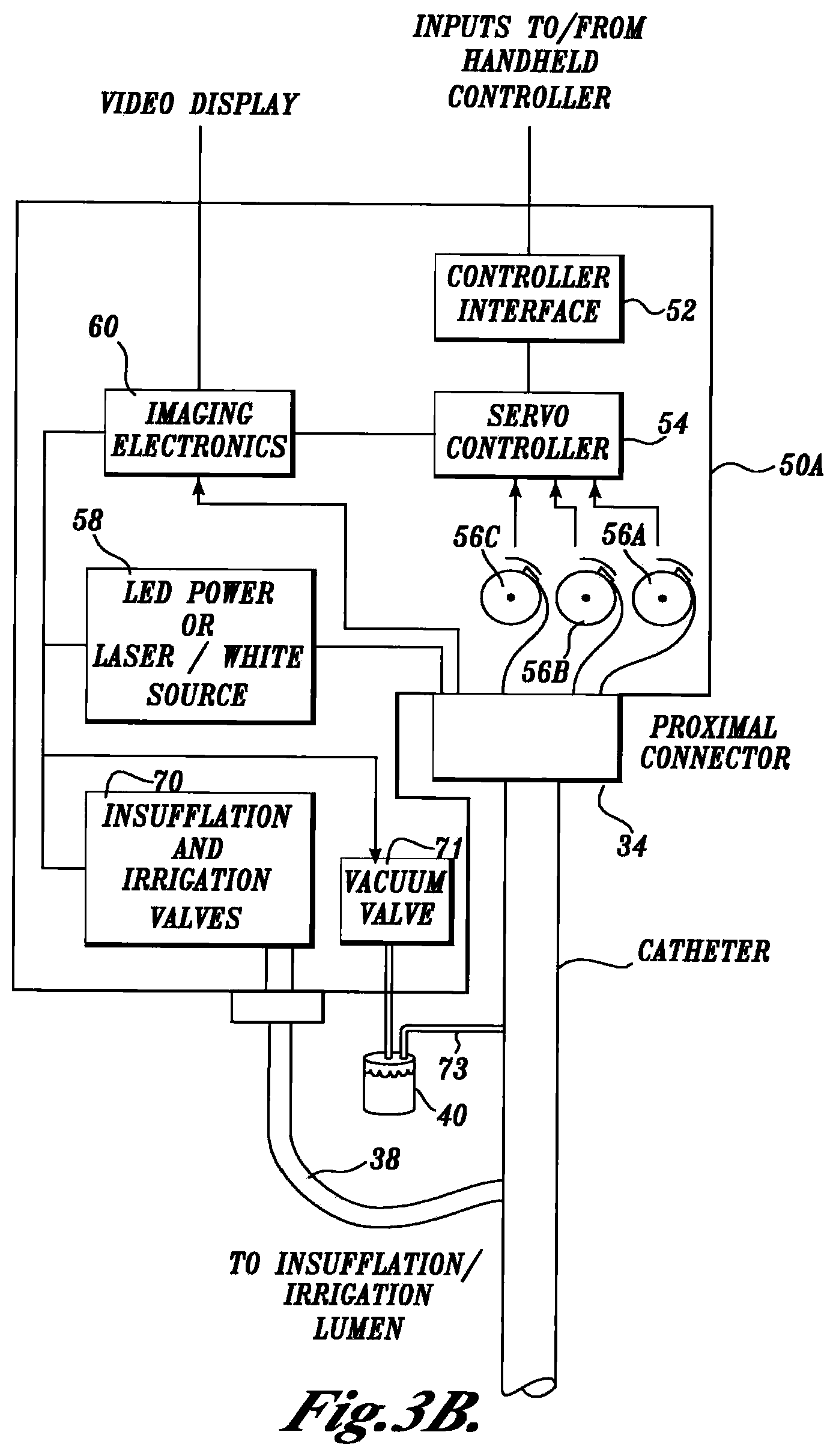
FIG. 3B is a block diagram of a motion control cabinet that interfaces with an imaging endoscope in accordance with another embodiment of the present invention;
FIGS. 4A-4D illustrate one mechanism for connecting the vision endoscope to a motion control cabinet;
FIG. 5 is a detailed view of one embodiment of a handheld controller for controlling an imaging endoscope;
FIG. 6 illustrates one embodiment of a distal tip of an imaging endoscope in accordance with the present invention;
FIG. 7 illustrates one mechanism for terminating a number of control cables in a distal tip of an imaging endoscope;
FIG. 8 illustrates an imaging endoscope having control cables routed through lumens in the walls of an endoscope shaft;
FIGS. 9A and 9B illustrate a transition guide that routes control cables from a central lumen of an endoscope shaft to lumens in an articulation joint;
FIGS. 10A and 10B illustrate the construction of a shaft portion of an endoscope in accordance with one embodiment of the present invention;
FIG. 11 illustrates one mechanism for providing a shaft having a varying stiffness along its length;
FIGS. 12A and 12B illustrate an extrusion used to make an articulation joint in accordance with one embodiment of the present invention;
FIG. 13 illustrates an articulation joint in accordance with one embodiment of the present invention;
FIGS. 14 and 15 illustrate an extrusion having areas of a different durometer that is used to form an articulation joint in accordance with another embodiment of the present invention;
FIGS. 16A and 16B illustrate another embodiment of an articulation joint including a number of ball and socket sections;
FIGS. 17A-17D illustrate various possible configurations of ball and socket sections used to construct an articulation joint;
FIGS. 18A-18B illustrate an articulation joint formed of a number of stacked discs in accordance with another embodiment of the present invention;
FIGS. 19A-19B illustrate a disc used to form an articulation joint in accordance with another embodiment of the present invention;
FIGS. 20A-20B illustrate a disc used to form an articulation joint in accordance with another embodiment of the present invention;
FIGS. 21A-21B illustrate a non-circular segment used to form an articulation joint in accordance with another embodiment of the present invention;
FIG. 22 illustrates an endoscope having a braided member as an articulation joint in accordance with another embodiment of the present invention;
FIG. 23 illustrates one possible technique for securing the ends of a control wire to a braided articulation joint;
FIG. 24 illustrates a shaft having one or more memory reducing wraps in accordance with another embodiment of the present invention;
FIG. 25 illustrates a shaft including longitudinal stripes of a high durometer material in accordance with another embodiment of the present invention;
FIGS. 26-29 illustrate alternative embodiments of a gripping mechanism that rotates an imaging endoscope shaft in accordance with the present invention;
FIGS. 30A and 30B illustrate a retractable sleeve used with another embodiment of the present invention;
FIG. 31 illustrates one embodiment of a heat dissipating distal tip of an endoscope in accordance with the present invention; and
FIGS. 32 and 33 illustrate alternative embodiments of a heat dissipating distal tip in accordance with the present invention.
DETAILED DESCRIPTION OF THE PREFERRED EMBODIMENT
As indicated above, the present invention is an endoscopic video imaging system that allows a physician to view internal body cavities of a patient as well as to insert surgical instruments into the patient's body. An imaging endoscope used with the present invention is sufficiently inexpensive to manufacture such that the endoscope can be considered a disposable item.
As shown in FIG. 1A, an endoscopic video imaging system 10 according to one embodiment of the present invention includes an imaging endoscope 20, a motion control cabinet 50 and a handheld controller 80. The imaging endoscope 20 has a distal tip 22 that is advanced into a patient's body cavity and a proximal end 24 that is connected to the motion control cabinet 50. As will be explained in further detail below, the motion control cabinet 50 includes a number of actuators that control a steering mechanism within the endoscope in order to change the orientation of the distal tip 22. A physician or their assistant uses the handheld controller 80 to input control signals that move the distal tip 22 of the imaging endoscope 20. In addition, the motion control cabinet 50 may include connections to sources of air/gas and a flushing liquid such as water for clearing the imaging endoscope. The motion control cabinet 50 also includes imaging electronics to create and/or transfer images received from an image sensor to a video display for viewing by a physician or technician.
In the embodiment shown, the imaging endoscope 20 also includes a breakout box 26 that is positioned approximately midway along the length of the endoscope. The breakout box 26 provides an attachment point for a vacuum bottle 40 that collects liquids from a lumen within the imaging endoscope. The vacuum bottle 40 is controlled by a vacuum valve 28 that is positioned on the breakout box 26. Alternatively, the valve can be positioned within the motion control cabinet 50 and controlled from the handheld controller 80.
If desired, the handheld controller 80 can be secured to the breakout box 26 such that the two units can be moved as one if desired. Upon completion of a patient examination procedure, the imaging endoscope 20 is disconnected from the motion control cabinet 50 and disposed of. A new imaging endoscope 20 is then connected to the motion control cabinet 50 for the next examination procedure to be performed.
The embodiment shown in FIG. 1A is a "parallel" configuration whereby the endoscope 20 and handheld controller 80 are separately plugged into different connectors of the motion control cabinet 50. This parallel configuration allows one operator to handle the endoscope while another operator can handle the handheld controller 80. Alternatively, the handheld controller 80 may be secured to the endoscope 20 such that a single operator can control both. FIG. 1B illustrates a "serial" configuration of the invention. Here, the imaging endoscope 20 is connected to the motion control cabinet 50 through the handheld controller 80.
FIG. 2 shows further detail of one embodiment of the imaging endoscope 20. At the proximal end of the endoscope is a low torque shaft 24 and a connector 34 that connects the endoscope 20 to the motion control cabinet 50. Distal to the breakout box 26 is a higher torque shaft. At the distal end of the endoscope 20 is the distal tip 22 that includes a light illumination port, an image sensor, an entrance to a working lumen and a flushing lumen (not shown). Proximal to the distal tip 22 is an articulation joint 30 that provides sufficient flexibility to the distal section of the shaft such that the distal tip 22 can be directed over an angle of 180 degrees by the steering mechanism.
As discussed above, the endoscope 20, in accordance with one embodiment of the invention, has a higher torque shaft at the distal section of the endoscope and a lower torque shaft at its proximal end. The breakout box 26 positioned along the length of the endoscope shaft can be used as a handle or gripper to impart rotation of the distal end of the endoscope during a medical examination procedure. The higher torque portion of the shaft transfers rotational motion that is imparted at a location proximal to the distal tip in order to guide the distal tip of the imaging catheter. The low torque shaft portion of the imaging catheter does not transfer torque as well and can twist when rotational motion is applied.
In use, the physician can insert a medical device such as a biopsy forceps, snare, etc., into a connector 32 found on the breakout box 26 that leads to a working channel lumen in the endoscope. In alternate embodiments, the entrance to the working channel lumen may be positioned further towards the proximal end of the endoscope.
FIG. 3A is a block diagram of the major components included within one embodiment of the motion control cabinet 50. The motion control cabinet is preferably positioned on a cart that is wheeled near a patient prior to an examination procedure. The motion control cabinet is connected to a source of electrical power, either A.C. mains or a battery, as well as to a source of insufflation gas and irrigation liquid. Inside the motion control cabinet 50 is a controller interface 52 that is connected to the handheld controller 80 and receives control signals therefrom. To change the orientation of the distal tip of the imaging endoscope, the control signals are received from a directional switch in the handheld controller 80. The control signals are supplied to a servo motor controller 54 that in turn controls a number of actuators, such as servo motors 56a, 56b, 56c, 56d. Each of the servo motors 56a-56d is connected to one or more control cables within the imaging endoscope. Motion of the servo motors 56a-56d pulls or releases the control cables in order to change the orientation of the distal tip 22 of the imaging endoscope 20. Although the embodiment shown in FIG. 3A shows four servo motors and control cables, it will be appreciated that fewer or more servo motors and corresponding control cables could be used to move the distal tip. For example, some imaging endoscopes may use three control cables and three associated servo motors.
Also included in the motion control cabinet 50 is a power source 58 that provides electrical power to a light source such as a number of light emitting diodes (LEDs) at the distal end 22 of the imaging endoscope. Alternatively, if the imaging catheter utilizes an external light source, then the motion control cabinet can include a high intensity light source such as a laser or Xenon white light source that supplies light to a fiber optic illumination guide within the imaging endoscope 20 in order to illuminate an internal body organ. The power source 58 may be controlled by control signals received from the handheld controller 80 when the user desires to activate the light source.
An imaging electronics board 60 captures images received from an image sensor (not shown) at the distal end of the imaging endoscope. The imaging electronics board 60 can enhance the images received or can provide video effects such as zoom, color changes, highlighting, etc., prior to display of the images on a video display (not shown). Images of the tissue may also be analyzed by the imaging electronics board 60 to produce control signals that are supplied to the servo motor controller 54 in order to automatically steer the distal tip of the endoscope as will be discussed in further detail below. Images produced by the imaging electronics board 60 may also be printed on a digital printer, saved to a computer readable media such as a floppy disk, CD, DVD, etc., or a video tape for later retrieval and analysis by a physician.
Finally, the motion control cabinet 50 includes valves 70 that control the delivery of insufflation air/gas to insufflate a patient's body cavity and an irrigation liquid to flush out a body cavity and/or clean the imaging light source and image sensor at the distal end of the endoscope. The insufflation air/gas and irrigation liquid are connected to the imaging catheter via a connector 38 that connects to an irrigation/insufflation lumen of the imaging endoscope 20. In one embodiment of the invention, the irrigation and insufflation lumen are the same lumen in the imaging catheter. However, it will be appreciated that separate irrigation and insufflation lumens could be provided if desired and if space in the endoscope permits.
FIG. 3B illustrates another embodiment of a motion control cabinet 50A that is similar to the cabinet shown in FIG. 3A. The motion control cabinet 50A includes a vacuum valve 71 that controls vacuum delivered to a vacuum collection bottle 40. A vacuum line 73 connects to a vacuum lumen within the imaging endoscope 20. The vacuum valve 71 is controlled from the handheld controller 80.
FIGS. 4A-4D illustrate one mechanism for securing the proximal end of the imaging endoscope to the control cabinet 50 prior to performing an endoscopic examination. The control cabinet 50 includes a connector 34A having a number of shafts 57 that are driven by the servo motors 56 shown in FIGS. 3A and 3B. Each shaft 57 is shaped to be received in a corresponding spool on which the control cables are wound. Also included in the connector 34A are connections to the insufflation and irrigation valves 70 and vacuum valve 71 to provide air, water and vacuum to the endoscope.
FIGS. 4A and 4B illustrate one possible connector 34 found at the proximal end of the endoscope 20 for securing the endoscope to the motion control cabinet 50. The connector 34 includes a number of thumbscrews 77 or other quick release mechanisms that allow the connector 34 to be easily secured to the connector 34A on the motion control cabinet. As shown in FIG. 4C, the connector 34A includes a number of spools 79 about which the control cables are wound. Each spool is preferably threaded or grooved to prevent the control cables from binding on the spool during use. A cover may surround a portion of the spool to keep the control cables against the spool and to aid in supporting the spool within the connector 34. In one embodiment of the invention, the spools are prevented from rotating when the connector is not engaged with the motion control cabinet 50 by brakes 81 having pins that fit within corresponding slots in the spool. Once the connector 34 is mounted to the motion control cabinet 50, the brakes 81 are disengaged from the spool such that the spool can be moved by the servo motors. Electrical connections for the light source and image sensor as well as connections to the air and water valves can be found on the sides of the connector or on the rear face of the connector 34 to engage the valves, as shown in FIG. 4A.
FIG. 4D illustrates a cross-sectional view of a shaft 57 fitted within a spool 79. The shaft 57 is supported by a cylinder 59 having a spring 61 therein such that the shaft 57 is free to move within the cylinder 59. The cylinder 59 is directly coupled to the servo motors within the motion control cabinet. The spring 61 allows the shaft 57 to float such that the shaft can more easily align and engage the mating surface of the spool 79.
Upon insertion of the shaft 57 into the spool 79, the brake 81 is released, thereby allowing the spool 79 to be moved by rotation of the cylinder 59. In some instances, the brake 81 may be omitted, thereby allowing the spools 79 to freely rotate when the connector 34 is not engaged with the motion control cabinet 50.
FIG. 5 illustrates various controls located on the handheld controller 80 in accordance with one embodiment of the invention. The handheld controller 80 includes a controller body 82 that, in the parallel embodiment of the invention, is coupled to the motion control cabinet 50 by an electrical cord 84, a wireless radio frequency channel, an infrared or other optical link. If the connection is made with an electrical cord, a strain relief 86 is positioned at the junction of the electrical cord 84 and the body 82 of the controller to limit the bending of the electrical wires within the electrical cord 84. In the serial embodiment of the invention, the connection of the handheld controller 80 to the motion control cabinet 50 is made with a conductor that includes both the wires to transmit signals to the motion controllers and imaging systems, as well as a lumens to carry the insufflation air/gas and irrigation liquid. In addition, the control cables of the endoscope engage cables connected to the actuators in the motion control cabinet through the handheld controller 80.
Positioned in an ergonomic arrangement on the handheld controller 80 are a number of electrical switches. An articulation joystick 88 or other multi-positional device can be moved in a number of positions to allow the physician to orient the distal tip of the imaging endoscope in a desired direction. In order to guide the imaging endoscope manually, the physician moves the joystick 88 while watching an image on a video monitor or by viewing the position of the distal tip with another medial imaging technique such as fluoroscopy. As the distal tip of the endoscope is steered by moving the joystick 88 in the desired direction, the physician can push, pull and/or twist the endoscope to guide the distal tip in the desired direction.
A camera button 90 is provided to capture an image of an internal body cavity or organ in which the imaging endoscope 20 is placed. The images collected may be still images or video images. The images may be adjusted for contrast or otherwise enhanced prior to display or storage on a recordable media.
An irrigation button 92 activates an irrigation source to supply a liquid such as water through an irrigation lumen of the imaging endoscope. The liquid serves to clean an image sensor and the light source at the distal end of the endoscope as well as an area of the body cavity. An insufflation button 94 is provided to activate the insufflation source within the motion control cabinet 50 to supply air/gas through a lumen of the catheter. The supply of the insufflation gas expands portions of the body cavity around the distal tip of the endoscope so that the physician can more easily advance the endoscope or better see the tissue in front of the endoscope.
In one embodiment of the invention, the handle 82 also includes a thumb screw 96 for securing the handheld controller 80 to the breakout box 26 as indicated above. A corresponding set of threads on a breakout box 26 receive the thumb screw 96 in order to join the two parts together. One or more additional buttons 98 may also be provided to activate additional functions such as recording or printing images, adjusting light intensity, activating a vacuum control valve, etc., if desired. Handle 82 of handheld controller 80 may include a first planar surface 900 and a second planar surface 902 recessed from the first planar surface. First planar surface 900 and second planar surface 902 may face the same direction.
The endoscope of the present invention may also be steered automatically. Images received by the imaging electronics 60 are analyzed by a programmed processor to determine a desired direction or orientation of the distal tip of the endoscope. In the case of a colonoscopy, where the endoscope is advanced to the cecum, the processor controls the delivery of insufflation air/gas to inflate the colon, the processor then analyzes the image of the colon for a dark spot that generally marks the direction in which the scope is to be advanced. The processor then supplies control instructions to the servo controller 54 such that the distal tip is oriented in the direction of the dark spot located.
In other modes, a processor in the motion control cabinet causes the distal tip of the endoscope to move in a predefined pattern. For example, as the scope is being withdrawn, the distal tip may be caused to move in a search pattern such that all areas of a body cavity are scanned for the presence of disease. By using the automatic control of the distal tip, a physician only has to advance or retract the scope to perform an examination.
As will be described in further detail below, the imaging endoscope 20 generally comprises a hollow shaft having one or more lumens formed of polyethylene tubes which terminate at the distal tip 22. As shown in FIG. 6, one embodiment of a distal tip 110 comprises a cylinder having a distal section 112 and a proximal section 114. The proximal section 114 has a smaller diameter than the diameter of the distal section 112 in order to form a stepped shoulder region. The diameter of the shoulder is selected that shaft walls of the endoscope can seat on the shoulder region to form a smooth outer surface with the distal section 112. The distal face of the distal tip 110 includes a number of ports, including a camera port 116, one or more illumination ports 118, an access port or working channel lumen 120, and a directional flush port 122.
Fitted within the camera port 116 is an image sensor (not shown) that preferably comprises a CMOS imaging sensor or other solid state device and one or more glass or polymeric lenses that produce electronic signals representative of an image of the tissue in front of the camera port 116. The image sensor is preferably a low light sensitive, low noise video VGA, CMOS, color imager or higher resolution sensor such as SVGA, SXGA, or XGA. The video output of the sensor may be in any conventional format including PAL, NTSC or high definition video format.
The illumination port 118 houses one or more lenses and one or more light emitting diodes (LEDs) (not shown). The LEDs may be high intensity white light sources or may comprise colored light sources such as red, green and blue LEDs. With colored LEDs, images in different spectral bands may be obtained due to illumination with any one or more individual colors. White light images may be obtained by the simultaneous or sequential illumination of the colored LEDs and combining individual color images. As an alternative to LEDs, the light source may be external to the endoscope and the illumination light delivered to the illumination port with a fiber optic bundle.
The access port 120 is the termination point of the working channel or lumen of the endoscope 20. In the embodiment described above, the proximal end of the working channel terminates at the breakout box 26 as shown in FIG. 2. However, the working channel could terminate nearer the proximal end of the imaging catheter.
The directional flush port 122 includes a cap 124 that directs liquid supplied through an irrigation and insufflation lumen across the front face of the distal tip 110 in the direction of the camera port 116 and/or the illumination port 118. The cap 124 thereby serves to clean the camera port 116 and the illumination port 118 for a better view of the internal body cavity in which the imaging catheter is placed. In addition, the flushing liquid cleans an area of tissue surrounding the distal end of the endoscope.
FIG. 7 shows further detail of one embodiment of a distal tip 110 of the imaging endoscope. In this embodiment, the tip section 110 includes a number of counter bored holes 126 that are positioned around the circumference of the distal tip 110. The counter bored holes 126 receive swaged or flanged ends of the control cables that orient the distal tip. Tension on the control cables pull the distal tip 110 in the direction of the tensioning force.
FIG. 8 is a lengthwise, cross-sectional view of an imaging endoscope 20 in accordance with one embodiment of the present invention. The distal tip 110 is adhesively secured, welded or otherwise bonded within a center lumen at the distal end of the articulation joint 30. Secured to the proximal end of the articulation joint 30 is a distal end of a shaft 128. As discussed above, the shaft 128 is preferably stiffer or better able to transmit torque towards the distal end of the endoscope than at the proximal end of the endoscope.
The control cables 130 that move the distal tip of the endoscope are preferably made of a non-stretching material such as stainless steel or a highly oriented polyethylene-theralate (PET) string. The control cables may be routed within a center lumen of the shaft 128 or, as shown in FIG. 8, may be routed through lumens formed within the walls of the shaft. The control cables 130 extend through guides within the walls of articulation joint 30 and terminate either at the distal end of the articulation joint 30 or in the distal tip section 110.
If the control cables are routed through the center lumen of the shaft 128, the cables are preferably carried in stainless steel or plastic spiral wrapped lumens to prevent binding and a transition guide 140 such as that as shown in FIGS. 9A and 9B may be used to guide the control cables into the proximal end of the articulation joint. The transition guide 140 has a proximal end 142 that is secured within a lumen of the distal end of the shaft. A central body portion 144 of the transition guide 140 has a diameter equal to the outer diameter of the imaging endoscope. In addition, the body portion 144 includes a number of diagonal lumens 148 that extend from a center lumen of the proximal end 142 to an outer surface of a stepped distal end 146 of the transition guide. The distal end 146 is secured within a proximal end of the articulation joint 30. Control cables in the diagonally extending lumens 148 are therefore guided to the outer edge of the catheter where they extend through the guides or control cable lumens of the articulation joint 30.
FIGS. 10A, 10B illustrate one embodiment of a shaft that comprises the imaging endoscope 20. The shaft 160 has a cover 162 that may include a wire or other braid 164 embedded therein. The braid 164, if present, allows the torque characteristics of the shaft to be adjusted. The cover 162 may be formed by placing a sleeve over a mandrel. The braid 164 is placed over the sleeve and the mandrel is dipped into or sprayed with a coating material. Preferably the sleeve and coating material are made of polyurethane or other biocompatible materials such as polyethylene, polypropylene or polyvinyl alcohol. In addition, the interior lumen(s) and exterior of the shaft can be coated with a extrudable, hydrophilic, lubricious coating such as the HYDROPASS.TM. hydrophilic coating available from Boston Scientific, of Natick, Mass., and described in U.S. Pat. Nos. 5,702,754 and 6,048,620 which are herein incorporated by reference.
A plastic spiral wrap 166 such as spiral wire wrap available from Panduit Inc. is inserted into a lumen of the cover 162. The spiral wrap 166 prevents the shaft 160 from crushing as it is bent around a patient's anatomy.
In one embodiment of the shaft 160, the spiral wrap has a thickness of 0.060 inches and a pitch of 3/16 inch. However, it will be appreciated that other thicknesses of spiral wrap with a different pitch could be used to provide the desired column strength and bend modulus as well as to prevent kinking.
FIG. 11 shows one method of altering the torque fidelity of the distal and proximal portions of the shaft. The shaft 160 has a flexible section 170 that is proximal to the break out box and a stiffer section 172 that is distal to the break out box. The portion of the scope that is distal to the break out box has an increasing flexibility toward the distal tip and conversely a higher torque fidelity and column strength proximally. To increase the torque fidelity characteristics of the distal section 172 of the shaft, a braid 164 in that section includes two or more wires that are wound in opposite directions. In one embodiment, the wire braid has a pitch of 14-16 pik. However, the number of wires and their spacing can be adjusted as needed in order to tailor the torque fidelity of the shaft.
The proximal end 170 of the shaft 160 has a single spiral of wire 176 that is preferably wound in the same direction as the plastic spiral wrap 166 in the center lumen of the shaft 160. Again, the torque fidelity of the proximal end of the shaft 170 can be adjusted by adjusting the pitch and/or direction of the wire 176 and its flexibility.
As will be appreciated, the single wire spiral 176 provides some torque fidelity but does have the same torque fidelity as the dual wire braid in the distal section of the shaft. The single wire spiral 176 may be omitted from the proximal portion of the shaft if even less torque fidelity is desired.
In order to facilitate steering the distal tip of imaging endoscope, the endoscope includes an articulation joint that allows the distal tip to be turned back on itself, i.e., over an arc of 180 degrees, by the control cables. As shown FIG. 12A, 12B[,?] an articulation joint 200 is formed from a cylinder of a plastically deformable material having a central lumen 202, and a number of control wire lumens 204 located in the walls of the articulation joint. If desired, the space between the control wire lumens in the cylinder wall may be thinner such that the control wire lumens form bosses that extend into the central lumen of the cylinder. The control cable lumens 204 are preferably oriented at 120.degree. apart if three control cables are used or 90.degree. apart if four control cables are used.
To facilitate bending of the articulation joint, the cylinder includes a number of live hinges 220 formed along its length. As can be seen in FIG. 13, each live hinge 220 comprises a pair of opposing V-shaped cuts 230 on either side of the cylinder and are separated by a flexible web 232 that forms the bendable portion of the hinge. In the embodiment designed for four control cables, each live hinge is oriented at 90 degrees with respect to an adjacent hinge.
Upon retraction of a control cable, those live hinges having webs 232 that are in line with the retracting control cable do not bend. Those live hinges having webs that are not in line with the control cable will be closed, thereby bending the articulation joint in the direction of the control cable under tension.
Another advantage of the articulation joint shown in FIG. 13 is that the distal end of the scope can be retracted by pulling all the control cables simultaneously. This allows the physician to maneuver the distal tip in the body without having to move the remaining length of the endoscope. This may be useful when performing surgical procedures such as obtaining a biopsy or snaring polyps.
The articulation joint can be formed by extruding a cylinder with the central and control cable lumens in place and cutting the cylinder tube with a knife, laser, water jet, or other material removal mechanism to form the live hinges. Alternatively, the articulation joint can be molded with the live hinge joints in place. As will be appreciated, the angles of the V-shaped cuts that form the hinges may be uniform or may vary along the length of the articulation joint. Similarly, the distance between adjacent live hinges may be uniform or may vary in order to tailor the bending and torque fidelity characteristics of the articulation joint. In one embodiment of the invention, each live hinge has a closing angle of 30.degree. so that six hinges are required to provide 180.degree. of movement. The distal end of the articulation joint 200 may be counter-bored to receive the distal tip section 110 of the endoscope, as discussed above. Similarly, the proximal end of the articulation joint 200 is adapted to receive the distal end of the shaft of the endoscope. In the embodiment shown in FIG. 13, the control cable lumens 204 are aligned with the widest spacing of the live hinges and with the web portion of each hinge. However, it may be desirable to offset the control cable lumens 204 with respect to the hinges in order to lessen potential binding of the control cables in the hinge. As indicated above, the articulation joint should be made of a biocompatible material that will bend but will not collapse. Suitable materials include polyurethane, polyethylene, polypropylene, or other biocompatible polymers.
To prevent wear by the control cables as they are pulled by the actuation mechanism in the motion control cabinet, it may be desirable to produce the articulation joint from a material having areas of different durometers. As shown in FIGS. 14 and 15, a cylinder formed from an extruded tube 240 has alternating bands of a high durometer material 242 and a lower durometer material 244 around its circumference. The lumens 246 used to route the control cables are formed in the high durometer material to resist abrasion as the control cables are tensioned and released. In addition, the high durometer material also reduces friction between the control cables and the surrounding lumen. FIG. 15 illustrates an articulation joint where the control cable lumens are offset with respect to the orientation of the web portions 248 of the live hinges so that the control cables do not pass through the web portion of the hinge.
FIGS. 16A, 16B illustrate an alternative embodiment of an articulation joint. In this embodiment, the joint comprises a series of ball and socket connectors that are linked together. As shown in FIG. 16A, each connector includes a socket section 290 and a ball section 292. The ball section 292 fits in a socket section 290 of an adjacent connector. A lumen 294 extends axially through the ball section 292 to allow for passage of the wires that connect to the light source and the image sensor and tubes that carry irrigation fluids and insufflation gases. The ball and socket sections are preferably molded of a biocompatible polymer.
Each socket section can be formed with a fully formed ball section such as ball section 300 shown in FIG. 17A. Alternatively, a partial ball section such as ball section 304 can be formed on a socket section 306 as shown in FIG. 17B. To provide room for the control cables to move, the ball section can include slot 308 as shown in FIGS. 17A, 17B that cuts through the middle and sides of the ball section. Alternatively, a number of smaller slots 310 can be positioned around the circumference of the ball section as shown in FIGS. 17C and 17D. The slots allow the control cables to be shortened under tension. A number of holes 312 at the interface of the ball section and socket section allows passage of the control cables from the socket section into the ball section as shown in FIG. 17D.
In another embodiment of an articulation joint, the joint is made of a series of stacked discs that are positioned adjacent one another and move with respect to each other. As shown in FIG. 18A, a disc 350 comprises an annular ring 352 having a pair of rearward facing rocker surfaces or cams 354 and a pair of forward facing rocker surfaces or cams 356. The cams 354 are positioned 180.degree. apart on the rear surface of the annular ring 352, while the forward facing cams 356 are positioned 180 degrees apart on the forward face of the annular ring 352. In the embodiment shown, the forward cams 356 are oriented at 90.degree. with respect to the rear cams 354. Opposite each cam on the other side of the annular ring is a flat land section so that the cams of an adjacent disc may engage with and rock on the flat section. Holes 360 are drilled through the annular ring and through the cams for passage of the control cables. Upon tension of the control cables, the discs will rock on the surface of the cams 354, 356 thereby bending the articulation joint in the desired direction.
FIG. 18B shows an articulation joint made up of a series of stacked discs 350a, 350b, 350c . . . engaged with one another to form an articulation joint. A number of control cables 370a, 370b, 370c, 370d, pass through the discs and are used to pull the discs on the cam surfaces to move the joint in the desired direction.
FIGS. 19A and 19B show an alternative embodiment of the articulation joint shown in FIGS. 18A and 18B. In this embodiment, an articulation joint comprises a series of stacked discs 380, each comprising an annular ring having a pair of concave pockets 382 on its rear surface and a pair of correspondingly shaped convex cams 384 on its front surface. The concave pockets 382 are oriented at 90.degree. with respect to the convex cams 384 so that adjacent discs may be stacked such that the cams of a disc fit within the pockets of the adjacent disc. The corresponding shaped cams 384 and pockets 382 help prevent the discs from rotating with respect to one another. Holes or lumens 386 are formed through the annular ring 380 for passage of a number of control cables 390a, 390b, 390c, 390d, as shown in FIG. 19B. The holes or lumens 386 may be positioned at the center of the cams and pockets. However, the holes for the control cables may be offset from the position of the cams and pockets, if desired. Preferably discs 380 are molded from a biocompatible polymer having a relatively slick surface, such as polyurethane, polypropylene, or polyethylene, that reduces friction between adjacent cams and pockets.
FIGS. 20A and 20B show yet another alternative embodiment of an articulation joint. In this embodiment, the articulation joint is formed of a stack of discs, each of which comprises an annular ring. The annular ring has cams having an arcuate slot 392 molded therein that allows a control cable to move more freely in the cam as the disc is moved relative to an adjacent disc. As best shown in FIG. 20B, the slot 392 tapers from a widest point 394 at the outer edge of the cam to a narrow point 396 where the slot forms a cylindrical hole 398 that extends to the opposite edge of the annular ring 380. A control wire 390b is free to bend within the widened portion of the arcuate slot 392 as an adjacent disc is rotated.
Although the discs of the articulation joints shown in FIGS. 18-20 are generally circular in shape, it will be appreciated that other shapes could be used. FIGS. 21A and 21B show an articulation joint formed from a number of sections having a generally square outer shape. As shown in FIG. 21A, a section 400 is a square band having a pair of pins 402 that extend outwardly on opposite sides of the rear surface of the square section. On the opposite sides of the front surface are a pair of opposing circular recesses 404 that are sized to receive the round pins 402 of an adjacent section. The embodiment shown, the control cables are routed through holes or lumens in corner blocks 406 that are found in each corner of the square section 400. FIG. 21B shows two adjacent square sections 400a, 400b secured together. As can be seen, the section 400b can rotate up or down on its pins with respect to the adjacent section 400a. Although circular and square articulation sections have been shown, it will be appreciated that other segment shapes such as triangular or pentagonal, etc., could also be used to form an articulation joint.
In some environments, a full 180.degree. turning radius of the distal tip of the imaging endoscope may not be necessary. In those environments, the articulation joint may be replaced with a flexible member such as a braided stent. FIG. 22 shows an imaging endoscope 425 having a braided stent 430 as the articulation joint. The braided stent extends between a distal tip 432 and a connector 434 that joins the proximal end of the stent 430 with the distal end of a flexible shaft 436. A cover 438 extends over the flexible shaft 436 and the braided stent 430. Control cables (not shown) extend through a lumen of flexible shaft 436 and are used to pull the stent 430 such that the distal tip 432 is oriented in the desired direction. In addition, pulling all the control cables simultaneously allows the distal tip of the endoscope to be retracted.
FIG. 23 shows one method of securing the distal ends of the control cables to a braided stent 430. The control cables 440a, 440b, 440c, 440d can be woven through the wires of the stent 430 and terminated by forming loops around the wires that comprise the stent. Alternatively, the ends of the cables 440 can be soldered or adhesively secured to the wires of the stent.
In some embodiments, the articulation joint is designed to exert a restoring force so that imaging endoscope will tend to straighten upon the release of tension from the control cables. In other cases, it may be desirable to maintain the position of the distal tip in a certain direction. In that case, a construction as shown in FIG. 24 can be used. Here, the shaft of the imaging endoscope includes an inner sleeve 450 that is overlaid with two or more plastic spiral wraps 452, 454, and 456. Wrap 452 is wound in the clockwise direction while wrap 454 is wound in the counter-clockwise direction over the wrap 452 and the wrap 456 is wound in the same direction as the first wrap 452. The wraps are formed of a relatively coarse plastic material such that friction is created between the alternatingly wound layers of the wrap. A suitable material for the plastic wrap includes a braided polyester or polyurethane ribbon. Upon tension of the imaging endoscope by any of the control cables, the plastic spiral wraps will move with respect to each other and the friction between the overlapping wraps will tend to maintain the orientation of the imaging endoscope in the desired direction. The endoscope will remain in the desired direction until it is pulled in a different direction by the control cables. Covering the alternatingly wound spiral wraps 452, 454, and 456 is a braid 458. The braid is formed of one or more plastic or wire threads wound in alternate directions. An outer sleeve 460 covers the braid 458 to complete the shaft.
FIG. 25 shows another alternative embodiment of a shaft construction used in an imaging endoscope according to the present invention. The shaft includes a cover sheath 470 having bands of a high durometer material 472 and a low durometer material 474 that alternate around the circumference of the sheath 470. The high durometer material and low durometer materials form longitudinal strips that extend along the length of the shaft. Within the sheath 470 is a plastic spiral wrap 474 that prevents the shaft 470 from crushing as it is bent in a patient's anatomy. The high durometer materials add to the torque fidelity characteristics of the shaft. The width of the high durometer material strips compared to the low durometer material may be adjusted in accordance with the torque fidelity characteristics desired.
During examination with the imaging endoscope, the physician may need to twist the scope in order to guide it in the desired direction. Because the outer surface of the scope is preferably coated with a lubricant and it is round, it can be difficult for the physician to maintain an adequate purchase on the shaft in order to rotate it. As such, the imaging endoscope of the present invention may include a gripper mechanism that aids the physician in grasping the shaft for either rotating it or moving the shaft longitudinally. One embodiment of a shaft gripping device is shown in FIG. 26. Here, a gripper 500 comprises a u-shaped member having a pair of legs 502, 504 that are aligned with the longitudinal axis of an imaging endoscope 20. At the distal end of the legs 502, 504 are two 90.degree. bends 506, 508. The gripper 500 includes a hole 505 positioned at the curved bent portion of the gripper that joins the legs as well as holes in each of the 90.degree. sections 506, 508. The imaging endoscope passes through the holes such that the gripper 500 is slideable along the length of the shaft portion of the endoscope. The spring nature of the material used to fashion the gripper causes the legs 502, 504 to be biased away from the shaft of the endoscope. Only the friction of the opposing holes at the bent portions 506, 508 prevent the gripper 500 from freely sliding along the length of the shaft. On the inner surface of the legs 502, 504 are a pair of touch pads 510, 512, having an inner surface that is shaped to match the outer circumference of the shaft portion of the endoscope. When the physician squeezes the legs 502, 504 radially inward, the touch pads 510, 512 engage the shaft such that the physician can push or pull the endoscope or rotate it. Upon release of the legs 502, 504, the touch pads 510, 512 release from the surface of the shaft and the gripper 500 can be moved along the length of the shaft to another location if desired.
FIG. 27 shows a gripper similar to that of FIG. 26 with like parts being identified with the same reference numbers. In this embodiment, the gripper includes two hemispherical discs 520, 522, positioned on the outside surface of the legs 502, 504. The hemispherical surfaces 520, 522 are designed to fit within the hand of the physician and increase the radial distance from the gripper to the shaft such that it is easier to twist the shaft, if desired.
FIG. 28 shows yet another alternative embodiment of a shaft gripper. In this example, a gripper 550 comprises a u-shaped member having a pair of legs 552, 554, that are oriented perpendicularly to the longitudinal axis of the imaging endoscope 20. The legs 552, 554 include a recessed section 556, 558 that is shaped to receive the outer diameter of the shaft portion of the endoscope. A thumbscrew 560 is positioned at the distal end of the legs such that the legs can be drawn together and cause the legs 554, 556 to securely engage the shaft of the endoscope. Upon release of the thumbscrew 560, the legs 554, 552 are biased away from the shaft such that the gripper 550 can be moved. The shaft can be twisted by rotating the legs 552, 554, with respect to the longitudinal axis of the shaft.
FIG. 29 shows an alternative embodiment of the gripper 550 shown in FIG. 28. In this example, the gripper 580 includes a u-shaped member having a pair of legs 582, 584. At the distal end of each leg is a recess 586, 588 that is shaped to receive the outer diameter of the shaft. The shaft is placed in the recesses 586, 588, and a thumbscrew is positioned between the ends of the legs 582, 584, and the u-shaped bend in the gripper 580. By tightening the thumbscrew 590, the legs are compressed against the shaft of the imaging endoscope 20, thereby allowing the physician to rotate the endoscope by moving the gripper 580.
In one embodiment of the invention the endoscope has a movable sleeve that operates to keep the distal end of the endoscope clean prior to use and covers the end of the scope that was in contact with a patient after the scope has been used.
FIGS. 30A and 30B illustrate one embodiment of an endoscope 594 having a sponge 504 at its distal end. The sponge fits over the endoscope and has a peel off wrapper that may be removed and water or other liquid can be applied to the sponge. The water activates a hydrophilic coating so that the distal end of the endoscope has an increased lubricity. In addition, the sponge functions as a gripper when compressed allowing the physician to pull and/or twist the endoscope.
A collapsible sleeve 598 is positioned over the distal end of the endoscope and can be retracted to expose the lubricated distal tip of the probe. In one embodiment, the sleeve 598 is secured at its distal end to the sponge 594 and at its proximal end to the breakout box. Moving the sponge proximally retracts the sleeve so that the endoscope is ready for use. After a procedure, the sponge 594 is moved distally to extend the sleeve over the distal end of the endoscope. With the sleeve extended, any contaminants on the probe are less likely to contact the patient, the physician or staff performing the procedure.
In some instances, it may be desirable to limit the amount of heat that is dissipated at the distal end of the imaging endoscope. If light emitting diodes are used, they generate heat in the process of producing light for illumination. Similarly, the image sensor generates some heat during operation. In order to limit how hot the distal end of the endoscope may become and/or to provide for increased life for these components, it is necessary to dissipate the heat. One technique for doing so is to fashion a heat sink at the distal tip of the imaging endoscope. As shown in FIG. 31, a distal tip 600 includes a cap 602 and a heat dissipating section 604 that is made of a heat dissipating material such as a biocompatible metal. The heat dissipating section 604 includes a semicircular opening 606 having a relatively flat base 608 that extends approximately along the diameter of the heat dissipating section 604. The flat base 608 forms a pad upon which electrical components such as the LEDs and image sensor can be mounted with a thermally conductive adhesive or other thermally conductive material. The heat generating devices will transfer heat generated during operation to the heat dissipating section 604. The distal cover 602 covers the distal end of the heat dissipating section 604 in order to prevent the heat dissipating section 604 from touching the tissue in the body as well as to protect the body as the imaging catheter is moved in the patient. Prisms, lenses, or other light bending devices may be needed to bend light entering the distal end of the endoscope to any imaging electronics that are secured to the relatively flat base 608 of the heat dissipating section 604.
FIG. 32 shows a heat dissipating distal tip of an endoscope wherein the distal tip does not include a cover but is molded from a single piece of heat dissipating material such as a biocompatible metal. The heat dissipating section 620 again includes a semicircular opening with a relatively flat surface 622 that extends along the diameter of the section and on which heat generating electronic devices can be mounted. With a semicircular opening formed in the distal end of the heat dissipating distal tip 620, the illumination mechanism and image sensor are mounted on the flat surface 622. The irrigation port is oriented to direct water over the hemispherical cutout in order to clean the illumination mechanism and image sensor or image sensor lenses.
In yet another embodiment of the invention, the imaging devices at the distal end of the endoscope can be cooled by air or water passed through a lumen to the end of the endoscope and vented outside the body. For example, air under pressure may be vented through an orifice near the imaging electronics. The expansion of the air lowers its temperature where it cools the imaging electronics. The warmed air is then forced to the proximal end of the endoscope through an exhaust lumen. Alternatively, the endoscope may include a water delivery lumen that delivers water to a heat exchanger at the distal tip. Water warmed by the electronic components in the distal tip is removed in a water return lumen.
FIG. 33 shows an alternative embodiment of the heat dissipating distal tip shown in FIG. 31. In this example, the heat dissipating distal tip 640 has a number of scalloped channels 642 positioned around the circumference of the distal tip. The scalloped channels 642 increase the surface area of the heat dissipating distal tip, thereby further increasing the ability of the tip to dissipate heat from the illumination and imaging electronic devices.
Although the present endoscopic imaging system has many uses, it is particularly suited for performing colonoscopic examinations. In one embodiment, a 10-13 mm diameter prototype having a 0.060 inner spiral wrap with a pitch of 1/4 inch and coated with a hydrophilic coating was found to have a coefficient of friction of 0.15 compared to 0.85 for conventional endoscopes. In addition, the endoscope of the present invention required 0.5 lbs. of force to push it through a 2-inch U-shaped bend where a conventional endoscope could not pass through such a tight bend. Therefore, the present invention allows colonoscopes to be made inexpensively and lightweight so that they are more comfortable for the patient due to their lower coefficient of friction and better trackability.
In addition to performing colonoscopies, the endoscopic imaging system of the present invention is also useful with a variety of surgical devices including: cannulas, guidewires, sphincterotomes, stone retrieval balloons, retrieval baskets, dilatation balloons, stents, cytology brushes, ligation devices, electrohemostasis devices, sclerotherapy needles, snares and biopsy forceps.
Cannulas are used with the endoscopic imaging system to cannulate the sphincter of Odi or papilla to gain access to the bile or pancreatic ducts. Guidewires can be delivered down the working channel of the endoscope and used as a rail to deliver a surgical device to an area of interest. Sphincterotomes are used to open the papilla in order to place a stent or remove a stone from a patient. Stone retrieval balloons are used along with a guidewire to pull a stone out of a bile duct. Retrieval baskets are also used to remove stones from a bile duct. Dilatation balloons are used to open up strictures in the gastrointestinal, urinary or pulmonary tracts. Stents are used to open up strictures in the GI, urinary or pulmonary tracts. Stents can be metal or plastic, self-expanding or mechanically expanded, and are normally delivered from the distal end of a catheter. Cytology brushes are used at the end of guidewires to collect cell samples. Ligation devices are used to ligate varices in the esophagus. Band ligators employ elastic bands to cinch varices. Electrohemostasis devices use electrical current to cauterize bleeding tissue in the GI tract. Sclerotherapy needles are used to inject coagulating or sealing solutions into varices. Snares are used to remove polyps from the GI tract, and biopsy forceps are used to collect tissue samples.
Examples of specific surgical procedures that can be treated with the endoscopic imaging system of the present invention include the treatment of gastroesophageal reflux disease (GERD) by the implantation of bulking agents, implants, fundoplication, tissue scarring, suturing, or replacement of valves or other techniques to aid in closure of the lower esophageal sphincter (LES).
Another example of a surgical procedure is the treatment of morbid obesity by deploying implants or performing reduction surgery, gastric bypass and application or creating tissue folds to help patients lose weight.
Endoscopic mucosal resection (EMR) involves the removal of sessile polyps or flat lesions by filling them with saline or the like to lift them prior to resection. The endoscope of the present invention can be used to deliver needles, snares and biopsy forceps useful in performing this procedure.
In addition, the endoscopic imaging system of the present invention can be used to perform full-thickness resection (FTRD) in which a portion of a GI tract wall is excised and the wounds healed with staplers or fasteners. Finally, the endoscopic imaging system of the present invention can be used to deliver sclerosing agents to kill tissues or drug delivery agents to treat maladies of internal body tissues.
While the preferred embodiment of the invention has been illustrated and described, it will be appreciated that various changes can be made therein without departing from the scope of the invention. For example, although some of the disclosed embodiments use the pull wires to compress the length of the endoscope, it will be appreciated that other mechanisms such as dedicated wires could be used. Alternatively, a spring can be used to bias the endoscope distally and wires used to compress the spring thereby shortening the length of the endoscope. Therefore, the scope of the invention is to be determined from the following claims and equivalents thereof.
* * * * *
References
D00000
D00001
D00002
D00003
D00004
D00005
D00006
D00007
D00008
D00009
D00010
D00011
D00012
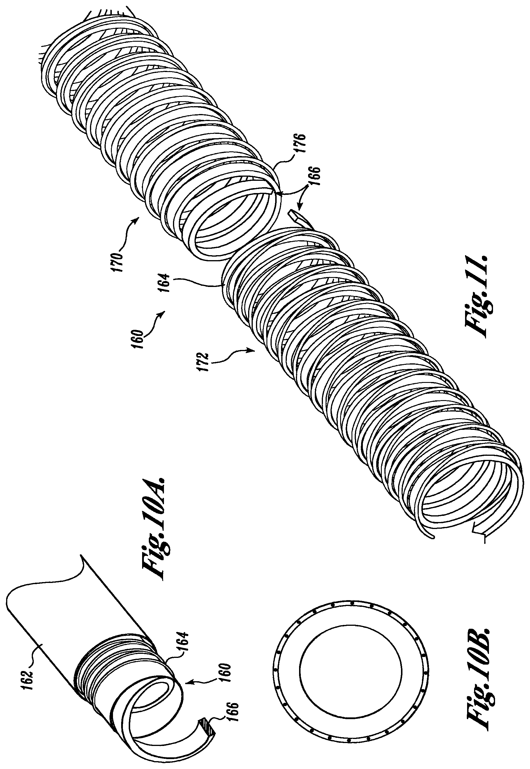
D00013

D00014
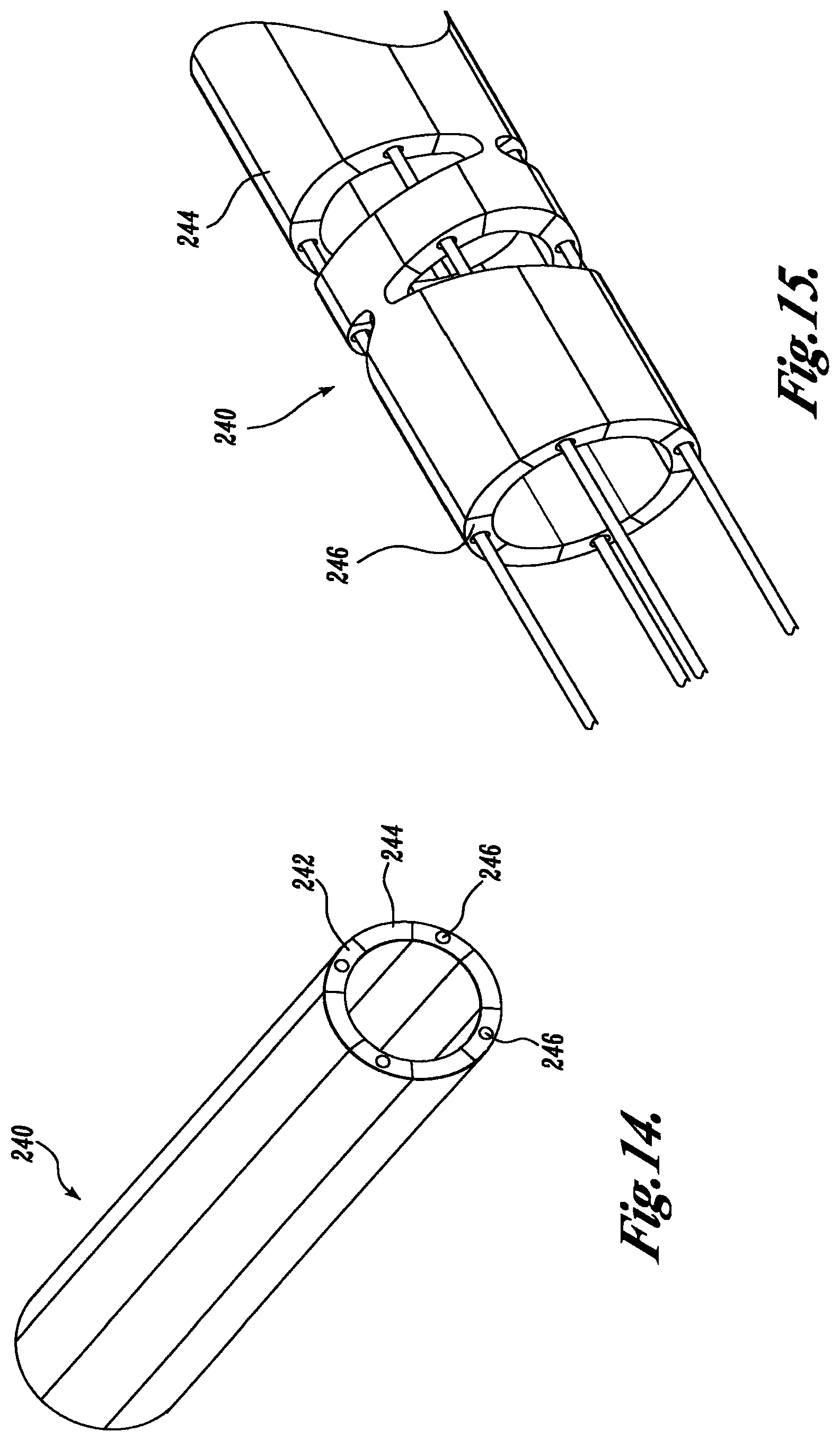
D00015

D00016

D00017

D00018

D00019

D00020

D00021

D00022

D00023

D00024

D00025

D00026

D00027

D00028

XML
uspto.report is an independent third-party trademark research tool that is not affiliated, endorsed, or sponsored by the United States Patent and Trademark Office (USPTO) or any other governmental organization. The information provided by uspto.report is based on publicly available data at the time of writing and is intended for informational purposes only.
While we strive to provide accurate and up-to-date information, we do not guarantee the accuracy, completeness, reliability, or suitability of the information displayed on this site. The use of this site is at your own risk. Any reliance you place on such information is therefore strictly at your own risk.
All official trademark data, including owner information, should be verified by visiting the official USPTO website at www.uspto.gov. This site is not intended to replace professional legal advice and should not be used as a substitute for consulting with a legal professional who is knowledgeable about trademark law.