Methods and apparatus for treating disorders of the ear nose and throat
Jenkins , et al.
U.S. patent number 10,702,295 [Application Number 15/814,984] was granted by the patent office on 2020-07-07 for methods and apparatus for treating disorders of the ear nose and throat. This patent grant is currently assigned to Acclarent, Inc.. The grantee listed for this patent is Acclarent, Inc.. Invention is credited to Eric Goldfarb, Daniel T. Harfe, Ronda M. Heiser, Thomas R. Jenkins, Christopher Larsen, Joshua Makower, Tom Thanh Vo, Robert N. Wood.


View All Diagrams
| United States Patent | 10,702,295 |
| Jenkins , et al. | July 7, 2020 |
Methods and apparatus for treating disorders of the ear nose and throat
Abstract
A device for dilating an ostium of a paranasal sinus of a human or animal subject may include: a handle; an elongate shaft having a proximal end coupled with the handle and extending to a distal end; a guidewire disposed through at least a portion of the shaft lumen; a dilator having a non-expanded configuration and an expanded configuration; and a slide member coupled with at least one of the guidewire or the dilator through the longitudinal opening of the shaft for advancing the guidewire and/or the dilator relative to the shaft.
| Inventors: | Jenkins; Thomas R. (Alameda, CA), Goldfarb; Eric (Belmont, CA), Vo; Tom Thanh (Mountain Views, CA), Makower; Joshua (Los Altos, CA), Wood; Robert N. (Indian Beach, NC), Heiser; Ronda M. (San Jose, CA), Larsen; Christopher (Oakland, CA), Harfe; Daniel T. (Los Altos, CA) | ||||||||||
|---|---|---|---|---|---|---|---|---|---|---|---|
| Applicant: |
|
||||||||||
| Assignee: | Acclarent, Inc. (Irvine,
CA) |
||||||||||
| Family ID: | 41202509 | ||||||||||
| Appl. No.: | 15/814,984 | ||||||||||
| Filed: | November 16, 2017 |
Prior Publication Data
| Document Identifier | Publication Date | |
|---|---|---|
| US 20180125515 A1 | May 10, 2018 | |
Related U.S. Patent Documents
| Application Number | Filing Date | Patent Number | Issue Date | ||
|---|---|---|---|---|---|
| 13858580 | Apr 8, 2013 | 9826999 | |||
| 12561147 | Apr 9, 2013 | 8414473 | |||
| 11193020 | Jul 29, 2005 | ||||
| 11150847 | Sep 28, 2010 | 7803150 | |||
| 11116118 | May 18, 2010 | 7720521 | |||
| 10944270 | Sep 17, 2004 | ||||
| 10829917 | Feb 2, 2010 | 7654997 | |||
| 61098157 | Sep 18, 2008 | ||||
| Current U.S. Class: | 1/1 |
| Current CPC Class: | A61B 1/126 (20130101); A61M 29/02 (20130101); A61M 25/09 (20130101); A61B 17/24 (20130101); A61M 25/10181 (20131105); A61B 1/0014 (20130101); A61B 1/233 (20130101); A61M 25/0068 (20130101); A61M 2025/09116 (20130101); A61M 25/1018 (20130101); A61B 2017/00535 (20130101); A61M 25/10186 (20131105); A61M 2210/0618 (20130101); A61M 25/10185 (20131105) |
| Current International Class: | A61B 17/24 (20060101); A61M 25/09 (20060101); A61B 1/12 (20060101); A61M 29/02 (20060101); A61B 1/233 (20060101); A61M 25/00 (20060101); A61B 1/00 (20060101); A61M 25/10 (20130101); A61B 17/00 (20060101) |
References Cited [Referenced By]
U.S. Patent Documents
| 446173 | February 1891 | Hancock |
| 504424 | September 1893 | De Pezzer |
| 513667 | January 1894 | Buckingham |
| 705346 | July 1902 | Hamilton |
| 798775 | September 1905 | Forsyte |
| 816792 | April 1906 | Green |
| 1080934 | December 1913 | Shackleford |
| 1200267 | October 1916 | Sunnergren |
| 1650959 | November 1927 | Pitman |
| 1735519 | November 1929 | Vance |
| 1828986 | October 1931 | Stevens |
| 1878671 | September 1932 | Cantor |
| 2201749 | May 1940 | Vandegrift |
| 2493326 | January 1950 | Trinder |
| 2525183 | October 1950 | Robison |
| 2847997 | August 1958 | Tibone |
| 2899227 | August 1959 | Jeanrenaud |
| 2906179 | September 1959 | Bower |
| 2995832 | August 1961 | Alderson |
| 3009265 | November 1961 | Bexark |
| 3037286 | June 1962 | Bower |
| 3173418 | March 1965 | baran |
| 3347061 | October 1967 | Stuemky |
| 3376659 | April 1968 | Asin et al. |
| 3384970 | May 1968 | Avalear |
| 3393073 | July 1968 | Reutenauer et al. |
| 3435826 | April 1969 | Fogarty |
| 3447061 | May 1969 | Russell et al. |
| 3469578 | September 1969 | Bierman |
| 3477438 | November 1969 | Allen et al. |
| 3481043 | December 1969 | Esch |
| 3486539 | December 1969 | Jacuzzi |
| 3506005 | April 1970 | Gilio et al. |
| 3509638 | May 1970 | Macleod |
| 3515137 | June 1970 | Santomieri |
| 3515888 | June 1970 | Lewis |
| 3527220 | September 1970 | Summers |
| 3531868 | October 1970 | Stevenson |
| 3552384 | January 1971 | Pierie et al. |
| 3624661 | November 1971 | Shebanow |
| 3731963 | May 1973 | Pond |
| 3766924 | October 1973 | Pidgeon |
| 3792391 | February 1974 | Ewing |
| 3802096 | April 1974 | Matern |
| 3804081 | April 1974 | Kinoshita |
| 3800788 | July 1974 | White |
| 3834394 | September 1974 | Hunter et al. |
| 3847145 | November 1974 | Grossan |
| 3850176 | November 1974 | Gottschalk |
| 3856000 | December 1974 | Chikama |
| 3859993 | January 1975 | Bitner |
| 3871365 | March 1975 | Chikama |
| 3894538 | July 1975 | Richter |
| 3903893 | September 1975 | Scheer |
| 3910617 | October 1975 | Scalza et al. |
| 3921636 | November 1975 | Zaffaroni |
| 3948254 | April 1976 | Zaffaroni |
| 3948262 | April 1976 | Zaffaroni |
| 3967618 | July 1976 | Zaffaroni |
| 3993069 | November 1976 | Buckles et al. |
| 3993072 | November 1976 | Zaffaroni |
| 3993073 | November 1976 | Zaffaroni |
| 4016251 | April 1977 | Higuchi et al. |
| 4052505 | October 1977 | Higuchi et al. |
| 4053975 | October 1977 | Olbrich et al. |
| 4069307 | January 1978 | Higuchi et al. |
| 4102342 | July 1978 | Akiyama et al. |
| 4138151 | February 1979 | Nakao |
| 4184497 | January 1980 | Kolff et al. |
| 4198766 | April 1980 | Camin et al. |
| 4207890 | June 1980 | Mamajek et al. |
| 4209919 | July 1980 | Kirikae et al. |
| 4213095 | July 1980 | Falconer |
| 4217898 | August 1980 | Theeuwes |
| 4268115 | May 1981 | Slemon et al. |
| 4299226 | November 1981 | Banka |
| 4299227 | November 1981 | Lincoff |
| 4311146 | January 1982 | Wonder |
| 4312353 | January 1982 | Shahbabian |
| 4338941 | July 1982 | Payton |
| D269204 | May 1983 | Trepp |
| 4388941 | June 1983 | Reidhammer |
| RE31351 | August 1983 | Falconer |
| 4435716 | March 1984 | Zandbergen |
| 4437856 | March 1984 | Valli |
| 4441495 | April 1984 | Hicswa |
| 4445892 | May 1984 | Hussein et al. |
| 4450150 | May 1984 | Sidman |
| 4459977 | July 1984 | Pizon et al. |
| 4464175 | August 1984 | Altman et al. |
| 4471779 | September 1984 | Antoshkiw et al. |
| 4499899 | February 1985 | Lyons, III |
| 4517979 | May 1985 | Pecenka |
| 4554929 | November 1985 | Samson et al. |
| 4564364 | January 1986 | Zaffaroni et al. |
| 4571239 | February 1986 | Heyman |
| 4571240 | February 1986 | Samson et al. |
| 4581017 | April 1986 | Sahota |
| 4585000 | April 1986 | Hershenson |
| D283921 | May 1986 | Dyak |
| 4589868 | May 1986 | Dretler |
| 4592357 | June 1986 | Ersek |
| 4596528 | June 1986 | Lewis et al. |
| D284892 | July 1986 | Glassman |
| 4603564 | August 1986 | Kleinhany et al. |
| 4606346 | August 1986 | Berg et al. |
| 4607622 | August 1986 | Fritch et al. |
| 4637389 | January 1987 | Heyden |
| 4639244 | January 1987 | Rizk et al. |
| 4641654 | February 1987 | Samson et al. |
| 4645495 | February 1987 | Vaillancourt |
| 4669469 | June 1987 | Gifford, III |
| 4672961 | June 1987 | Davies |
| 4675613 | June 1987 | Naegeli et al. |
| 4682607 | July 1987 | Vaillancourt et al. |
| 4686965 | August 1987 | Bonnet et al. |
| 4691948 | September 1987 | Austin, Jr. et al. |
| 4696544 | September 1987 | Costella |
| 4700694 | October 1987 | Shishido |
| 4708434 | November 1987 | Tsuno |
| 4708834 | November 1987 | Cohen et al. |
| 4726772 | February 1988 | Amplatz |
| 4736970 | April 1988 | McGourty et al. |
| 4737141 | April 1988 | Spits |
| 4748869 | June 1988 | Ohtsuka |
| 4748969 | June 1988 | Wardle |
| 4748986 | June 1988 | Morrison et al. |
| 4753637 | June 1988 | Horneffer |
| 4755171 | July 1988 | Tennant |
| 4771776 | September 1988 | Powell et al. |
| 4784117 | November 1988 | Miyazaki |
| 4793359 | December 1988 | Sharrow |
| 4795439 | January 1989 | Guest |
| 4796629 | January 1989 | Grayzel |
| 4803076 | February 1989 | Ranade |
| 4811743 | March 1989 | Stevens |
| 4815478 | March 1989 | Buchbinder et al. |
| 4819619 | April 1989 | Augustine et al. |
| 4834709 | May 1989 | Banning et al. |
| 4846186 | July 1989 | Box et al. |
| 4847258 | July 1989 | Sturm et al. |
| 4851228 | July 1989 | Zentner et al. |
| 4854330 | August 1989 | Evans, III et al. |
| 4862874 | September 1989 | Kellner |
| 4867138 | September 1989 | Kubota et al. |
| 4883465 | November 1989 | Brennan |
| 4897651 | January 1990 | DeMonte |
| 4898577 | February 1990 | Badger et al. |
| 4917419 | April 1990 | Mora, Jr. et al. |
| 4917667 | April 1990 | Jackson |
| 4919112 | April 1990 | Siegmund |
| 4920967 | May 1990 | Cottonaro et al. |
| 4925445 | May 1990 | Sakamoto et al. |
| 4940062 | July 1990 | Hampton et al. |
| 4943275 | July 1990 | Stricker |
| 4946466 | August 1990 | Pinchuk et al. |
| 4953553 | September 1990 | Tremulis |
| 4961433 | October 1990 | Christian |
| 4966163 | October 1990 | Kraus et al. |
| 4976691 | December 1990 | Sahota |
| 4984581 | January 1991 | Stice |
| 4986810 | January 1991 | Semrad |
| 4991588 | February 1991 | Pflueger et al. |
| 4994033 | February 1991 | Shockey et al. |
| 4998916 | March 1991 | Hammerslag et al. |
| 4998917 | March 1991 | Gaiser et al. |
| 5001825 | March 1991 | Halpern |
| 5002322 | March 1991 | Fukumoto |
| 5009655 | April 1991 | Daignault, Jr. et al. |
| 5019075 | May 1991 | Spears et al. |
| 5019372 | May 1991 | Folkman et al. |
| 5020514 | June 1991 | Heckele |
| 5021043 | June 1991 | Becker et al. |
| 5024650 | June 1991 | Hagiwara et al. |
| 5024658 | June 1991 | Kozlov et al. |
| 5026384 | June 1991 | Farr et al. |
| 5030227 | July 1991 | Rosenbluth et al. |
| 5040548 | August 1991 | Yock |
| 5041089 | August 1991 | Mueller et al. |
| 5044369 | September 1991 | Sahota |
| 5044678 | September 1991 | Detweiler |
| 5049132 | September 1991 | Shaffer et al. |
| 5053007 | October 1991 | Euteneuer |
| 5055051 | October 1991 | Duncan |
| 5060660 | October 1991 | Gambale et al. |
| 5067489 | November 1991 | Lind |
| 5069226 | December 1991 | Yamauchi et al. |
| 5084010 | January 1992 | Plaia et al. |
| 5087244 | February 1992 | Wolinsky et al. |
| 5087246 | February 1992 | Smith |
| 5090595 | February 1992 | Vandeninck |
| 5090910 | February 1992 | Narlo |
| 5090959 | February 1992 | Samson et al. |
| 5099845 | March 1992 | Besz et al. |
| 5102402 | April 1992 | Dror et al. |
| 5112228 | May 1992 | Zouras |
| 5116311 | May 1992 | Lofstedt |
| 5127393 | July 1992 | McFarlin et al. |
| 5137517 | August 1992 | Loney et al. |
| 5139510 | August 1992 | Goldsmith, III et al. |
| 5139832 | August 1992 | Hayashi et al. |
| D329496 | September 1992 | Wotton |
| 5152747 | October 1992 | Olivier |
| 5152749 | October 1992 | Giesy |
| 5156595 | October 1992 | Adams |
| 5161534 | November 1992 | Berthiaume |
| 5163989 | November 1992 | Campbell et al. |
| 5165420 | November 1992 | Strickland |
| 5167220 | December 1992 | Brown |
| 5168864 | December 1992 | Skockey |
| 5169386 | December 1992 | Becker et al. |
| 5171233 | December 1992 | Amplatz et al. |
| 5180368 | January 1993 | Garrison |
| 5183470 | February 1993 | Wettermann |
| 5189110 | February 1993 | Ikematu et al. |
| 5195168 | March 1993 | Yong |
| 5195971 | March 1993 | Sirhan |
| 5197457 | March 1993 | Adair |
| 5201908 | April 1993 | Jones |
| 5207695 | May 1993 | Trout, III |
| 5211952 | May 1993 | Spicer et al. |
| 5213576 | May 1993 | Abiuso et al. |
| 5215105 | June 1993 | Kizelshteyn et al. |
| 5221260 | June 1993 | Burns et al. |
| 5226302 | July 1993 | Anderson |
| 5230348 | July 1993 | Ishibe et al. |
| 5236422 | August 1993 | Eplett, Jr. |
| 5238004 | August 1993 | Sahatjian et al. |
| 5243996 | September 1993 | Hall |
| D340111 | October 1993 | Yoshikawa |
| 5250059 | October 1993 | Andreas et al. |
| 5251092 | October 1993 | Brady et al. |
| 5252183 | October 1993 | Shaban et al. |
| 5255679 | October 1993 | Imran |
| 5256144 | October 1993 | Kraus et al. |
| 5263926 | November 1993 | Wilk |
| 5264260 | November 1993 | Saab |
| 5267965 | December 1993 | Deneiga |
| 5269752 | December 1993 | Bennett |
| 5270086 | December 1993 | Hamlin |
| 5273052 | December 1993 | Kraus et al. |
| 5275593 | January 1994 | Easley et al. |
| 5286254 | February 1994 | Shapland et al. |
| 5290310 | March 1994 | Makower et al. |
| 5292305 | March 1994 | Boudewijn et al. |
| 5295694 | March 1994 | Levin |
| 5300085 | April 1994 | Yock |
| 5304123 | April 1994 | Atala et al. |
| 5306272 | April 1994 | Cohen et al. |
| 5308326 | May 1994 | Zimmon |
| 5312430 | May 1994 | Rosenbluth et al. |
| 5313967 | May 1994 | Lieber et al. |
| 5314408 | May 1994 | Salmon et al. |
| 5314417 | May 1994 | Stephens et al. |
| 5314443 | May 1994 | Rudnick |
| 5315618 | May 1994 | Yoshida |
| 5318528 | June 1994 | Heaven et al. |
| 5324306 | June 1994 | Makower et al. |
| 5333620 | August 1994 | Moutafis et al. |
| 5334143 | August 1994 | Carroll |
| 5334167 | August 1994 | Cocanower |
| 5334187 | August 1994 | Fischell et al. |
| 5335671 | August 1994 | Clement |
| 5336163 | August 1994 | DeMane et al. |
| 5341818 | August 1994 | Abrams et al. |
| 5342296 | August 1994 | Persson et al. |
| 5343865 | September 1994 | Gardineer et al. |
| 5345945 | September 1994 | Hodgson et al. |
| 5346075 | September 1994 | Nichols et al. |
| 5346508 | September 1994 | Hastings |
| 5348537 | September 1994 | Wiesner et al. |
| 5350396 | September 1994 | Eliachar |
| 5356418 | October 1994 | Shturman |
| 5368049 | November 1994 | Raman et al. |
| 5368558 | November 1994 | Nita |
| 5368566 | November 1994 | Crocker |
| 5370640 | December 1994 | Koloff |
| 5372138 | December 1994 | Crowley et al. |
| 5372584 | December 1994 | Zink et al. |
| D355031 | January 1995 | Yoshikawa |
| 5378234 | January 1995 | Hammerslag et al. |
| 5385562 | January 1995 | Adams et al. |
| 5386817 | February 1995 | Jones |
| 5386828 | February 1995 | Owens et al. |
| 5391147 | February 1995 | Imran et al. |
| 5391179 | February 1995 | Mezzoli |
| 5395367 | March 1995 | Wilk |
| 5402799 | April 1995 | Colon et al. |
| 5409444 | April 1995 | Kensey |
| 5411475 | May 1995 | Atala et al. |
| 5411476 | May 1995 | Abrams et al. |
| 5411477 | May 1995 | Saab |
| 5415633 | May 1995 | Lazarus |
| 5425370 | June 1995 | Vilkomerson |
| 5439446 | August 1995 | Barry |
| 5441494 | August 1995 | Ortiz |
| 5441497 | August 1995 | Narciso, Jr. |
| 5445646 | August 1995 | Euteneuer et al. |
| 5450853 | September 1995 | Hastings et al. |
| 5451221 | September 1995 | Cho et al. |
| 5454817 | October 1995 | Katz |
| 5458572 | October 1995 | Campbell et al. |
| 5458615 | October 1995 | Klemm |
| 5459700 | October 1995 | Jacobs |
| 5465717 | November 1995 | Imran et al. |
| 5465733 | November 1995 | Hinohara et al. |
| 5478309 | December 1995 | Sweezer et al. |
| 5478565 | December 1995 | Geria |
| 5486181 | January 1996 | Cohen et al. |
| 5496338 | March 1996 | Miyagi et al. |
| 5497783 | March 1996 | Urick et al. |
| 5507301 | April 1996 | Wasicek et al. |
| 5507725 | April 1996 | Savage et al. |
| 5507766 | April 1996 | Kugo et al. |
| 5507795 | April 1996 | Chiang et al. |
| 5512055 | April 1996 | Domb et al. |
| 5514128 | May 1996 | Hillsman et al. |
| 5519532 | May 1996 | Broome |
| 5531676 | July 1996 | Edwards et al. |
| 5533985 | July 1996 | Wang |
| 5538008 | July 1996 | Crowe |
| 5546964 | August 1996 | Stangerup |
| 5549542 | August 1996 | Kovalcheck |
| 5558073 | September 1996 | Pomeranz et al. |
| 5558101 | September 1996 | Brooks |
| 5558652 | September 1996 | Henke |
| 5562619 | October 1996 | Mirarchi et al. |
| 5568809 | October 1996 | Ben-Haim |
| 5571086 | November 1996 | Kaplan et al. |
| 5578007 | November 1996 | Imran |
| 5578048 | November 1996 | Pasqualucci et al. |
| 5582575 | December 1996 | Heckele et al. |
| 5584827 | December 1996 | Korteweg et al. |
| 5591194 | January 1997 | Berthiaume |
| 5599284 | February 1997 | Shea |
| 5599304 | February 1997 | Shaari |
| 5599576 | February 1997 | Opolski |
| 5601087 | February 1997 | Gunderson et al. |
| 5601594 | February 1997 | Best |
| 5607386 | March 1997 | Flam |
| 5617870 | April 1997 | Hastings et al. |
| 5626374 | May 1997 | Kim |
| 5633000 | May 1997 | Grossman et al. |
| 5634908 | June 1997 | Loomas |
| 5638819 | June 1997 | Manwaring et al. |
| 5643251 | July 1997 | Hillsman et al. |
| 5645789 | July 1997 | Roucher, Jr. |
| 5647361 | July 1997 | Damadian |
| 5653690 | August 1997 | Booth et al. |
| 5656030 | August 1997 | Hunjan et al. |
| 5662674 | September 1997 | Debbas |
| 5664567 | September 1997 | Linder |
| 5664580 | September 1997 | Erickson et al. |
| 5665052 | September 1997 | Bullard |
| 5669388 | September 1997 | Vilkomerson |
| 5673707 | October 1997 | Chandrasekaran |
| 5676673 | October 1997 | Ferre et al. |
| 5679400 | October 1997 | Tuch |
| 5682199 | October 1997 | Lankford |
| 5685838 | November 1997 | Peters et al. |
| 5685847 | November 1997 | Barry |
| 5690373 | November 1997 | Luker |
| 5693065 | December 1997 | Rains, III |
| 5694945 | December 1997 | Ben-Haim |
| 5697159 | December 1997 | Linden |
| 5700286 | December 1997 | Tartaglia et al. |
| 5707376 | January 1998 | Kavteladze et al. |
| 5707389 | January 1998 | Louw et al. |
| 5708175 | January 1998 | Loyanagi et al. |
| 5711315 | January 1998 | Jerusalmy |
| 5713839 | February 1998 | Shea |
| 5713946 | February 1998 | Ben-Haim |
| 5718702 | February 1998 | Edwards |
| 5720300 | February 1998 | Fagan et al. |
| 5720719 | February 1998 | Edwards et al. |
| 5722401 | March 1998 | Pietroski et al. |
| 5722984 | March 1998 | Fischell et al. |
| 5729129 | March 1998 | Acker |
| 5730128 | March 1998 | Pomeranz et al. |
| 5733248 | March 1998 | Adams et al. |
| 5749357 | May 1998 | Linder |
| 5749920 | May 1998 | Quiachon et al. |
| 5752513 | May 1998 | Acker et al. |
| 5752971 | May 1998 | Rosenbluth et al. |
| 5762604 | June 1998 | Kieturakis |
| 5766158 | June 1998 | Opolski |
| 5769821 | June 1998 | Abrahamson et al. |
| 5775327 | July 1998 | Randolph et al. |
| 5776158 | July 1998 | Chou |
| 5779699 | July 1998 | Lipson |
| 5789391 | August 1998 | Jacobus et al. |
| 5792100 | August 1998 | Shantha |
| 5797878 | August 1998 | Bleam |
| 5803089 | September 1998 | Ferre et al. |
| 5814016 | September 1998 | Valley et al. |
| 5819723 | October 1998 | Joseph |
| 5820568 | October 1998 | Willis |
| 5820592 | October 1998 | Hammerslag |
| 5823961 | October 1998 | Fields et al. |
| 5824044 | October 1998 | Quiachon et al. |
| 5824048 | October 1998 | Tuch |
| 5824173 | October 1998 | Fontirroche et al. |
| 5826576 | October 1998 | West |
| 5827224 | October 1998 | Shippert |
| 5827323 | October 1998 | Klieman et al. |
| 5830188 | November 1998 | Abouleish |
| 5833608 | November 1998 | Acker |
| 5833645 | November 1998 | Lieber et al. |
| 5833650 | November 1998 | Imran |
| 5833682 | November 1998 | Amplatz et al. |
| 5836638 | November 1998 | Slocum |
| 5836935 | November 1998 | Ashton et al. |
| 5836951 | November 1998 | Rosenbluth et al. |
| 5837313 | November 1998 | Ding et al. |
| 5843089 | December 1998 | Shatjian et al. |
| 5843113 | December 1998 | High |
| 5846259 | December 1998 | Berthiaume |
| 5857998 | January 1999 | Barry |
| 5862693 | January 1999 | Myers et al. |
| 5865767 | February 1999 | Frechette et al. |
| 5872879 | February 1999 | Hamm |
| 5873835 | February 1999 | Hastings |
| 5879324 | March 1999 | Von Hoffmann |
| 5882333 | March 1999 | Schaer et al. |
| 5882346 | March 1999 | Pomeranz et al. |
| 5887467 | March 1999 | Butterweck et al. |
| 5902247 | May 1999 | Coe et al. |
| 5902333 | May 1999 | Roberts et al. |
| 5904701 | May 1999 | Daneshvar |
| 5908407 | June 1999 | Frazee et al. |
| 5916193 | June 1999 | Stevens et al. |
| 5916213 | June 1999 | Haissaguerre et al. |
| 5928192 | July 1999 | Maahs |
| 5931811 | August 1999 | Haissaguerre et al. |
| 5931818 | August 1999 | Werp et al. |
| 5932035 | August 1999 | Koger et al. |
| 5935061 | August 1999 | Acker et al. |
| 5935098 | August 1999 | Blaisdell |
| 5941816 | August 1999 | Barthel et al. |
| D413629 | September 1999 | Wolff et al. |
| 5947988 | September 1999 | Smith |
| 5949929 | September 1999 | Hamm |
| 5954693 | September 1999 | Barry |
| 5954694 | September 1999 | Sunseri |
| 5957842 | September 1999 | Littmann et al. |
| 5967984 | October 1999 | Chu et al. |
| 5968085 | October 1999 | Morris et al. |
| 5971975 | October 1999 | Mills et al. |
| 5976074 | November 1999 | Moriyama |
| 5979290 | November 1999 | Simeone |
| 5980503 | November 1999 | Chin |
| 5980551 | November 1999 | Summers et al. |
| 5984945 | November 1999 | Sirhan |
| 5985307 | November 1999 | Hanson et al. |
| 5987344 | November 1999 | West |
| 5993462 | November 1999 | Pomeranz et al. |
| 5997562 | December 1999 | Zadno-Azizi et al. |
| 6006126 | December 1999 | Cosman |
| 6006130 | December 1999 | Higo et al. |
| 6007516 | December 1999 | Burbank et al. |
| 6007991 | December 1999 | Sivaraman et al. |
| 6010511 | January 2000 | Murphy |
| 6013019 | January 2000 | Fischell et al. |
| 6015414 | January 2000 | Werp et al. |
| 6016429 | January 2000 | Khafizov et al. |
| 6016439 | January 2000 | Acker |
| 6019736 | February 2000 | Avellanet et al. |
| 6019777 | February 2000 | Mackenzie |
| 6021340 | February 2000 | Randolph et al. |
| 6022313 | February 2000 | Ginn et al. |
| 6027461 | February 2000 | Walker et al. |
| 6027478 | February 2000 | Katz |
| 6039699 | March 2000 | Viera |
| 6042561 | March 2000 | Ash et al. |
| 6048299 | April 2000 | von Hoffmann |
| 6048358 | April 2000 | Barak |
| 6053172 | April 2000 | Hovda et al. |
| 6056702 | May 2000 | Lorenzo |
| 6059752 | May 2000 | Segal |
| 6063022 | May 2000 | Ben-Haim |
| 6063079 | May 2000 | Hovda et al. |
| 6071233 | June 2000 | Ishikawa et al. |
| 6079755 | June 2000 | Chang |
| 6080190 | June 2000 | Schwartz |
| 6083148 | July 2000 | Williams |
| 6083188 | July 2000 | Becker et al. |
| 6086585 | July 2000 | Hovda et al. |
| 6092846 | July 2000 | Fuss et al. |
| 6093150 | July 2000 | Chandler et al. |
| 6093195 | July 2000 | Ouchi |
| 6102891 | August 2000 | van Erp et al. |
| 6109268 | August 2000 | Thapliyal et al. |
| 6113567 | September 2000 | becker |
| 6117105 | September 2000 | Bresnaham et al. |
| 6122541 | September 2000 | Cosman et al. |
| 6123697 | September 2000 | Shippert |
| 6135991 | October 2000 | Muni et al. |
| 6136006 | October 2000 | Johnson et al. |
| 6139510 | October 2000 | Palermo |
| 6142957 | November 2000 | Diamond et al. |
| 6146402 | November 2000 | Munoz |
| 6146415 | November 2000 | Fitz |
| 6148823 | November 2000 | Hastings |
| 6149213 | November 2000 | Sokurenko et al. |
| 6159170 | December 2000 | Borodulin et al. |
| 6171298 | January 2001 | Matsuura et al. |
| 6171303 | January 2001 | Ben-Haim |
| 6174280 | January 2001 | Oneda et al. |
| 6176829 | January 2001 | Vilkomerson |
| 6179776 | January 2001 | Adams et al. |
| 6179788 | January 2001 | Sullivan |
| 6179811 | January 2001 | Fugoso et al. |
| 6183433 | February 2001 | Bays |
| 6183461 | February 2001 | Matsuura et al. |
| 6183464 | February 2001 | Sharp et al. |
| 6190353 | February 2001 | Makower et al. |
| 6190360 | February 2001 | Iancea |
| 6190381 | February 2001 | Olsen et al. |
| 6193650 | February 2001 | Ryan, Jr. |
| 6195225 | February 2001 | Komatsu et al. |
| 6200257 | March 2001 | Winkler |
| 6206870 | March 2001 | Kanner |
| 6206900 | March 2001 | Tabatabaei et al. |
| 6213975 | April 2001 | Laksin |
| 6217585 | April 2001 | Houser |
| 6221042 | April 2001 | Adams |
| 6231543 | May 2001 | Hegde et al. |
| 6234958 | May 2001 | Snoke et al. |
| 6238364 | May 2001 | Becker |
| 6238391 | May 2001 | Olsen et al. |
| 6238430 | May 2001 | Klumb et al. |
| 6241519 | June 2001 | Sedleemayer |
| 6248092 | June 2001 | Miraki et al. |
| 6249180 | June 2001 | Maalej et al. |
| 6254550 | July 2001 | McNamara et al. |
| 6264087 | July 2001 | Whitman |
| 6268574 | July 2001 | Edens |
| 6270477 | August 2001 | Bagaoisan et al. |
| 6280433 | August 2001 | McIvor et al. |
| 6283908 | September 2001 | Powell et al. |
| 6290689 | September 2001 | Delaney et al. |
| 6293957 | September 2001 | Peters et al. |
| 6295990 | October 2001 | Lewis et al. |
| 6302875 | October 2001 | Makower et al. |
| 6304768 | October 2001 | Blume et al. |
| 6306105 | October 2001 | Rooney et al. |
| 6306124 | October 2001 | Jones et al. |
| D450382 | November 2001 | Nestenborg |
| 6322495 | November 2001 | Snow et al. |
| 6328564 | December 2001 | Thurow |
| 6328730 | December 2001 | Harkrider, Jr. |
| 6332089 | December 2001 | Acker et al. |
| 6332891 | December 2001 | Himes |
| 6340360 | January 2002 | Lyles et al. |
| 6344028 | February 2002 | Barry |
| 6348041 | February 2002 | Klint |
| 6352503 | March 2002 | Matsui et al. |
| 6364856 | April 2002 | Ding et al. |
| 6375615 | April 2002 | Flaherty et al. |
| 6375629 | April 2002 | Muni et al. |
| 6379319 | April 2002 | Garibotto et al. |
| 6381485 | April 2002 | Hunter et al. |
| 6383146 | May 2002 | Klint |
| 6386197 | May 2002 | Miller |
| 6389313 | May 2002 | Marchitto et al. |
| 6390993 | May 2002 | Cornish et al. |
| 6394093 | May 2002 | Lethi |
| 6398758 | June 2002 | Jacobsen et al. |
| 6409863 | June 2002 | Williams et al. |
| 6419653 | July 2002 | Edwards et al. |
| 6423012 | July 2002 | Kato et al. |
| 6425877 | July 2002 | Edwards |
| 6432986 | August 2002 | Levin |
| 6436119 | August 2002 | Erb et al. |
| 6440061 | August 2002 | Wenner et al. |
| 6443947 | September 2002 | Marko et al. |
| 6445939 | September 2002 | Swanson et al. |
| 6450975 | September 2002 | Brennan et al. |
| 6450989 | September 2002 | Dubrul et al. |
| 6464650 | October 2002 | Jafari et al. |
| 6468202 | October 2002 | Irion et al. |
| 6468297 | October 2002 | Williams et al. |
| 6485475 | November 2002 | Chelly |
| 6488653 | December 2002 | Lombardo |
| 6491940 | December 2002 | Levin |
| 6494894 | December 2002 | Mirarchi |
| 6500130 | December 2002 | Kinsella et al. |
| 6500189 | December 2002 | Lang et al. |
| 6503087 | January 2003 | Eggert et al. |
| 6503185 | January 2003 | Waksman et al. |
| 6503263 | January 2003 | Adams |
| 6511418 | January 2003 | Shahidi et al. |
| 6511471 | January 2003 | Rosenman et al. |
| 6514249 | February 2003 | Maguire et al. |
| 6517478 | February 2003 | Khadem |
| 6520954 | February 2003 | Ouchi |
| 6524129 | February 2003 | Cote et al. |
| 6524299 | February 2003 | Tran et al. |
| 6526302 | February 2003 | Hassett |
| 6527753 | March 2003 | Sekine et al. |
| 6529756 | March 2003 | Phan et al. |
| 6533754 | March 2003 | Hisamatsu et al. |
| 6536437 | March 2003 | Dragisic |
| 6537294 | March 2003 | Boyle et al. |
| 6543452 | April 2003 | Lavigne |
| 6544223 | April 2003 | Kokish |
| 6544230 | April 2003 | Flaherty et al. |
| 6549800 | April 2003 | Atalar et al. |
| 6551239 | April 2003 | Renner et al. |
| 6562022 | May 2003 | Hoste et al. |
| 6569146 | May 2003 | Werner et al. |
| 6569147 | May 2003 | Evans et al. |
| 6571131 | May 2003 | Nguyen |
| 6572538 | June 2003 | Takase |
| 6572590 | June 2003 | Stevens et al. |
| 6579285 | June 2003 | Sinofsky |
| 6585639 | July 2003 | Kotmel et al. |
| 6585717 | July 2003 | Wittenberger et al. |
| 6585718 | July 2003 | Hayzelden et al. |
| 6585794 | July 2003 | Shimoda et al. |
| 6589164 | July 2003 | Flaherty |
| 6589237 | July 2003 | Woloszko et al. |
| 6591130 | July 2003 | Shahidi |
| 6596009 | July 2003 | Jelic |
| 6607546 | August 2003 | Murken |
| 6610059 | August 2003 | West, Jr. |
| 6612999 | September 2003 | Brennan et al. |
| 6613066 | September 2003 | Fukaya et al. |
| 6616601 | September 2003 | Hayakawa |
| 6616659 | September 2003 | de la Torre et al. |
| 6616678 | September 2003 | Nishtala et al. |
| 6616913 | September 2003 | Mautone |
| 6619085 | September 2003 | Hsieh |
| 6634684 | October 2003 | Spiessl |
| 6638233 | October 2003 | Corvi et al. |
| 6638268 | October 2003 | Niazi |
| 6638291 | October 2003 | Ferrera et al. |
| 6645193 | November 2003 | Mangosong |
| 6645223 | November 2003 | Boyle et al. |
| 6652472 | November 2003 | Jafari et al. |
| 6652480 | November 2003 | Imran et al. |
| 6656166 | December 2003 | Lurie et al. |
| 6659106 | December 2003 | Hovda et al. |
| 6663589 | December 2003 | Halevy |
| 6669689 | December 2003 | Lehmann et al. |
| 6669711 | December 2003 | Noda |
| 6672773 | January 2004 | Glenn et al. |
| 6673025 | January 2004 | Richardson et al. |
| 6679833 | January 2004 | Smith et al. |
| 6679871 | January 2004 | Hahnen |
| 6685648 | February 2004 | Flaherty et al. |
| 6689096 | February 2004 | Loubens et al. |
| 6689146 | February 2004 | Himes |
| 6702735 | March 2004 | Kelly |
| 6712757 | March 2004 | Becker et al. |
| 6714809 | March 2004 | Lee et al. |
| 6716183 | April 2004 | Clayman et al. |
| 6716216 | April 2004 | Boucher et al. |
| 6716813 | April 2004 | Lim et al. |
| 6719749 | April 2004 | Schweikert et al. |
| 6719763 | April 2004 | Chung et al. |
| 6726701 | April 2004 | Gilson et al. |
| 6738656 | May 2004 | Ferre et al. |
| 6740191 | May 2004 | Clarke et al. |
| 6741884 | May 2004 | Freeman et al. |
| 6755812 | June 2004 | Peterson et al. |
| 6758857 | July 2004 | Cioanta et al. |
| 6776772 | August 2004 | de Vrijer et al. |
| 6780168 | August 2004 | Jellie |
| 6783522 | August 2004 | Fischell |
| 6783536 | August 2004 | Vilsmeier et al. |
| 6786864 | September 2004 | Matsuura et al. |
| 6796960 | September 2004 | Cioanta et al. |
| 6811544 | November 2004 | Schaer |
| 6817364 | November 2004 | Garibaldi et al. |
| 6817976 | November 2004 | Rovegno |
| 6827683 | December 2004 | Otawara |
| 6827701 | December 2004 | MacMahon et al. |
| 6832715 | December 2004 | Eungard et al. |
| D501677 | February 2005 | Becker |
| 6849062 | February 2005 | Kantor |
| 6851290 | February 2005 | Meier et al. |
| 6855136 | February 2005 | Dorros et al. |
| 6860264 | March 2005 | Christopher |
| 6860849 | March 2005 | Matsushita et al. |
| 6866669 | March 2005 | Buzzard et al. |
| 6878106 | April 2005 | Herrmann |
| 6890329 | May 2005 | Carroll et al. |
| 6899672 | May 2005 | Chin et al. |
| 6902556 | June 2005 | Grimes et al. |
| 6913763 | July 2005 | Lerner |
| 6927478 | August 2005 | Paek |
| 6939361 | September 2005 | Kleshinski |
| 6939374 | September 2005 | Banik et al. |
| 6953431 | October 2005 | Barthel |
| 6955657 | October 2005 | Webler |
| 6966906 | November 2005 | Brown |
| 6971998 | December 2005 | Rosenman et al. |
| 6979290 | December 2005 | Mourlas et al. |
| 6979979 | December 2005 | Xu et al. |
| 6984203 | January 2006 | Tartaglia et al. |
| 6989024 | January 2006 | Hebert et al. |
| 6991597 | January 2006 | Gellman et al. |
| 6997931 | February 2006 | Sauer et al. |
| 6997941 | February 2006 | Sharkey et al. |
| 7004173 | February 2006 | Sparks et al. |
| 7004176 | February 2006 | Lau |
| 7008412 | March 2006 | Maginot |
| 7011654 | March 2006 | Dubrul et al. |
| 7022105 | April 2006 | Edwards |
| 7037321 | May 2006 | Sachdeva |
| 7043961 | May 2006 | Pandey |
| 7044964 | May 2006 | Jang et al. |
| 7048711 | May 2006 | Rosemann et al. |
| 7052474 | May 2006 | Castell et al. |
| 7056284 | June 2006 | Martone et al. |
| 7056287 | June 2006 | Taylor et al. |
| 7056303 | June 2006 | Dennis et al. |
| 7056314 | June 2006 | Florio et al. |
| 7074197 | July 2006 | Reynolds et al. |
| 7074426 | July 2006 | Kochinke |
| 7097612 | August 2006 | Bertolero et al. |
| 7108677 | September 2006 | Courtney et al. |
| 7108706 | September 2006 | Hogle |
| 7117039 | October 2006 | Manning et al. |
| 7128718 | October 2006 | Hojeibane et al. |
| 7131969 | November 2006 | Hovda et al. |
| 7140480 | November 2006 | Drussel et al. |
| D534216 | December 2006 | Makower et al. |
| 7160255 | January 2007 | Saadat |
| 7169140 | January 2007 | Kume |
| 7169163 | January 2007 | Becker |
| 7172562 | February 2007 | McKinley |
| 7174774 | February 2007 | Pawar et al. |
| 7182735 | February 2007 | Shireman et al. |
| 7184827 | February 2007 | Edwards |
| 7186224 | March 2007 | Windheuser |
| 7207981 | April 2007 | Quinn et al. |
| 7214201 | May 2007 | Burmeister et al. |
| 7233820 | June 2007 | Gilboa |
| 7235099 | June 2007 | Duncavage et al. |
| 7237313 | July 2007 | Skujins et al. |
| 7248914 | July 2007 | Hastings et al. |
| 7252677 | August 2007 | Burwell et al. |
| 7282057 | October 2007 | Surti et al. |
| 7292885 | November 2007 | Scott et al. |
| 7294345 | November 2007 | Haapakumpu et al. |
| 7294365 | November 2007 | Hayakawa et al. |
| 7303533 | December 2007 | Johansen et al. |
| 7309334 | December 2007 | von Hoffmann |
| 7313430 | December 2007 | Urquhart et al. |
| 7316168 | January 2008 | van der Knokke et al. |
| 7316656 | January 2008 | Shireman et al. |
| 7318831 | January 2008 | Alvarez et al. |
| 7322934 | January 2008 | Miyake et al. |
| 7326235 | February 2008 | Edwards |
| 7338467 | March 2008 | Lutter |
| 7343920 | March 2008 | Toby et al. |
| 7347868 | March 2008 | Burnett et al. |
| 7359755 | April 2008 | Jones et al. |
| 7361168 | April 2008 | Makower et al. |
| 7366562 | April 2008 | Dukesherer |
| 7371210 | May 2008 | Brock et al. |
| 7381205 | June 2008 | Thommen |
| 7384407 | June 2008 | Rodriguez et al. |
| 7410480 | August 2008 | Muni et al. |
| 7419497 | September 2008 | Muni et al. |
| 7438701 | October 2008 | Theeuwes et al. |
| 7442191 | October 2008 | Hovda et al. |
| 7452351 | November 2008 | Miller et al. |
| 7454244 | November 2008 | Kassab et al. |
| 7462175 | December 2008 | Chang et al. |
| 7471994 | December 2008 | Ford et al. |
| 7481218 | January 2009 | Djupesland |
| 7481800 | January 2009 | Jacques |
| D586465 | February 2009 | Faulkner et al. |
| D586916 | February 2009 | Faulkner et al. |
| 7488313 | February 2009 | Segal et al. |
| 7488337 | February 2009 | Saab et al. |
| 7493156 | February 2009 | Manning et al. |
| 7500971 | March 2009 | Chang et al. |
| D590502 | April 2009 | Geisser et al. |
| 7520876 | April 2009 | Ressemann et al. |
| 7532920 | May 2009 | Ainsworth et al. |
| 7544192 | June 2009 | Eaton et al. |
| 7551758 | June 2009 | Florent et al. |
| 7559925 | July 2009 | Goldfarb et al. |
| 7566300 | July 2009 | Devierre et al. |
| 7610104 | October 2009 | Kaplan et al. |
| 7615005 | November 2009 | Stefanchik et al. |
| 7618450 | November 2009 | Zarowski et al. |
| 7625335 | December 2009 | Deichmann et al. |
| 7632291 | December 2009 | Stephens et al. |
| 7634233 | December 2009 | Deng et al. |
| 7641644 | January 2010 | Chang et al. |
| 7641668 | January 2010 | Perry et al. |
| 7645272 | January 2010 | Chang et al. |
| 7648367 | January 2010 | Makower et al. |
| 7654997 | February 2010 | Makower et al. |
| 7680244 | March 2010 | Gertner et al. |
| 7686798 | March 2010 | Eaton et al. |
| 7691120 | April 2010 | Shluzas et al. |
| 7697972 | April 2010 | Verard et al. |
| 7717933 | May 2010 | Becker |
| 7720521 | May 2010 | Chang et al. |
| 7727186 | June 2010 | Makower et al. |
| 7727226 | June 2010 | Chang et al. |
| 7736301 | June 2010 | Webler et al. |
| 7740642 | June 2010 | Becker |
| 7751758 | July 2010 | Yahagi |
| 7753929 | July 2010 | Becker |
| 7753930 | July 2010 | Becker |
| 7758497 | July 2010 | Hern |
| 7771409 | August 2010 | Chang et al. |
| 7775968 | August 2010 | Mathis |
| 7785315 | August 2010 | Muni et al. |
| 7799048 | September 2010 | Hudson et al. |
| 7799337 | September 2010 | Levin |
| 7803150 | September 2010 | Chang et al. |
| 7833282 | November 2010 | Mandpe |
| 7837672 | November 2010 | Intoccia |
| 7840254 | November 2010 | Glossop |
| 7854744 | December 2010 | Becker |
| 7857750 | December 2010 | Belafsky |
| D630321 | January 2011 | Hamilton, Jr. |
| 7875050 | January 2011 | Samson et al. |
| D632791 | February 2011 | Murner |
| 7881769 | February 2011 | Sobe |
| 7883717 | February 2011 | Varner et al. |
| 7896891 | March 2011 | Catanese, III et al. |
| 7927271 | April 2011 | Dimitriou et al. |
| 7951132 | May 2011 | Eaton et al. |
| 7988705 | August 2011 | Galdonik et al. |
| 7993353 | August 2011 | Ro.beta.ner et al. |
| 8002740 | August 2011 | Willink et al. |
| 8014849 | September 2011 | Peckham |
| 8016752 | September 2011 | Armstrong et al. |
| 8025635 | September 2011 | Eaton et al. |
| 8075476 | December 2011 | Vargas |
| 8080000 | December 2011 | Makower et al. |
| 8088063 | January 2012 | Fujikura et al. |
| 8088101 | January 2012 | Chang et al. |
| 8090433 | January 2012 | Makower et al. |
| 8100933 | January 2012 | Becker |
| 8104483 | January 2012 | Taylor |
| 8114062 | February 2012 | Muni et al. |
| 8114113 | February 2012 | Becker |
| 8123722 | February 2012 | Chang et al. |
| 8142422 | March 2012 | Makower et al. |
| 8146400 | April 2012 | Goldfarb et al. |
| 8147545 | April 2012 | Avior |
| 8167821 | May 2012 | Sharrow |
| 8172828 | May 2012 | Chang et al. |
| 8190389 | May 2012 | Kim et al. |
| 8197433 | June 2012 | Cohen |
| 8197552 | June 2012 | Mandpe |
| 8249700 | August 2012 | Clifford et al. |
| 8277386 | October 2012 | Ahmed et al. |
| 8317816 | November 2012 | Becker |
| 8337454 | December 2012 | Eaton et al. |
| 8388642 | March 2013 | Muni et al. |
| 8403954 | March 2013 | Santin et al. |
| 8414473 | April 2013 | Jenkins et al. |
| 8425457 | April 2013 | John et al. |
| 8439687 | May 2013 | Morriss et al. |
| 8475360 | July 2013 | Brown |
| 8521259 | August 2013 | Mandrusov et al. |
| 8529439 | September 2013 | Ito et al. |
| 8535707 | September 2013 | Arensdorf et al. |
| 8702626 | April 2014 | Kim et al. |
| 8715169 | May 2014 | Chang et al. |
| 8721591 | May 2014 | Chang et al. |
| 8740839 | June 2014 | Eaton et al. |
| 8740929 | June 2014 | Gopferich et al. |
| 8747389 | June 2014 | Goldfarb et al. |
| 8764709 | July 2014 | Chang et al. |
| 8764726 | July 2014 | Chang et al. |
| 8764729 | July 2014 | Muni et al. |
| 8777926 | July 2014 | Chang et al. |
| 8802131 | August 2014 | Arensdorf et al. |
| 8828041 | September 2014 | Chang et al. |
| 8961398 | February 2015 | Makower |
| 9826999 | November 2017 | Jenkins |
| 2001/0004644 | June 2001 | Levin |
| 2001/0005785 | June 2001 | Sachse |
| 2001/0034530 | October 2001 | Malackowski et al. |
| 2002/0004666 | January 2002 | Schwager |
| 2002/0006961 | January 2002 | Katz et al. |
| 2002/0013548 | January 2002 | Hinchcliffe |
| 2002/0055746 | May 2002 | Burke et al. |
| 2002/0068851 | June 2002 | Gravenstein et al. |
| 2002/0077593 | June 2002 | Perkins et al. |
| 2002/0090388 | July 2002 | Humes et al. |
| 2002/0115982 | August 2002 | Barbut |
| 2002/0161389 | October 2002 | Boyle et al. |
| 2002/0188341 | December 2002 | Elliott |
| 2003/0009095 | January 2003 | Skarda |
| 2003/0013985 | January 2003 | Saadat |
| 2003/0017111 | January 2003 | Rabito |
| 2003/0018291 | January 2003 | Hill et al. |
| 2003/0040697 | February 2003 | Pass et al. |
| 2003/0051733 | March 2003 | Kotmel et al. |
| 2003/0055377 | March 2003 | Sirhan |
| 2003/0073900 | April 2003 | Senarith et al. |
| 2003/0074045 | April 2003 | Buzzard et al. |
| 2003/0083608 | May 2003 | Evans et al. |
| 2003/0114732 | June 2003 | Webler et al. |
| 2003/0114912 | June 2003 | Sequin |
| 2003/0163154 | August 2003 | Miyata et al. |
| 2003/0167060 | September 2003 | Buzzard |
| 2003/0220551 | November 2003 | Kimball et al. |
| 2004/0015150 | January 2004 | Zadno-Azizi |
| 2004/0018980 | January 2004 | Gurney et al. |
| 2004/0020492 | February 2004 | Dubrul et al. |
| 2004/0034311 | February 2004 | Mihakcik |
| 2004/0043052 | March 2004 | Hunter et al. |
| 2004/0058992 | March 2004 | Marinello et al. |
| 2004/0064105 | April 2004 | Capes et al. |
| 2004/0097988 | May 2004 | Gittings |
| 2004/0116958 | June 2004 | Gopferich et al. |
| 2004/0122503 | June 2004 | Campbell |
| 2004/0127820 | July 2004 | Clayman et al. |
| 2004/0158229 | August 2004 | Quinn |
| 2004/0181175 | September 2004 | Clayman et al. |
| 2004/0193073 | September 2004 | DeMello et al. |
| 2004/0220516 | November 2004 | Solomon et al. |
| 2004/0230156 | November 2004 | Schreck et al. |
| 2004/0236231 | November 2004 | Knighton et al. |
| 2004/0249243 | December 2004 | Kleiner |
| 2004/0249434 | December 2004 | Andreas |
| 2004/0267347 | December 2004 | Cervantes |
| 2005/0027249 | February 2005 | Reifart et al. |
| 2005/0038319 | February 2005 | Goldwasser et al. |
| 2005/0055077 | March 2005 | Marco |
| 2005/0059930 | March 2005 | Garrison et al. |
| 2005/0059931 | March 2005 | Garrison et al. |
| 2005/0080476 | April 2005 | Gunderson |
| 2005/0089670 | April 2005 | Large |
| 2005/0107738 | May 2005 | Slater et al. |
| 2005/0113687 | May 2005 | Herweck et al. |
| 2005/0113850 | May 2005 | Tagge |
| 2005/0119590 | June 2005 | Burmeister et al. |
| 2005/0124856 | June 2005 | Fujikura et al. |
| 2005/0131316 | June 2005 | Flagle et al. |
| 2005/0143687 | June 2005 | Rosenblatt et al. |
| 2005/0149159 | July 2005 | Andreas |
| 2005/0182319 | August 2005 | Glossop |
| 2005/0228224 | October 2005 | Okada et al. |
| 2005/0234507 | October 2005 | Geske et al. |
| 2005/0240120 | October 2005 | Modesitt |
| 2005/0244472 | November 2005 | Hughes et al. |
| 2005/0283221 | December 2005 | Mann et al. |
| 2006/0004323 | January 2006 | Chang et al. |
| 2006/0047261 | March 2006 | Joshi |
| 2006/0063973 | March 2006 | Makower et al. |
| 2006/0173382 | August 2006 | Schreiner |
| 2006/0189844 | August 2006 | Tien |
| 2006/0190022 | August 2006 | Beyar et al. |
| 2006/0211752 | September 2006 | Kohn et al. |
| 2006/0271024 | November 2006 | Gertner et al. |
| 2006/0284428 | December 2006 | Beadle et al. |
| 2007/0020196 | January 2007 | Pipkin et al. |
| 2007/0112358 | May 2007 | Abbott |
| 2007/0129751 | June 2007 | Muni et al. |
| 2007/0135789 | June 2007 | Chang et al. |
| 2007/0167682 | July 2007 | Goldfarb et al. |
| 2007/0207186 | September 2007 | Scanlon et al. |
| 2007/0208252 | September 2007 | Makower |
| 2007/0208301 | September 2007 | Evard et al. |
| 2007/0249896 | October 2007 | Goldfarb et al. |
| 2007/0269385 | November 2007 | Yun et al. |
| 2007/0282305 | December 2007 | Goldfarb et al. |
| 2007/0293727 | December 2007 | Goldfarb et al. |
| 2007/0293946 | December 2007 | Gonzales et al. |
| 2008/0015544 | January 2008 | Keith et al. |
| 2008/0033519 | February 2008 | Burwell et al. |
| 2008/0051804 | February 2008 | Cottler et al. |
| 2008/0097516 | April 2008 | Chang et al. |
| 2008/0103521 | May 2008 | Makower et al. |
| 2008/0119693 | May 2008 | Makower et al. |
| 2008/0125626 | May 2008 | Chang et al. |
| 2008/0132938 | June 2008 | Chang et al. |
| 2008/0172033 | July 2008 | Keith et al. |
| 2008/0183128 | July 2008 | Morriss et al. |
| 2008/0188803 | August 2008 | Jang |
| 2008/0188870 | August 2008 | Andre et al. |
| 2008/0195041 | August 2008 | Goldfarb et al. |
| 2008/0228085 | September 2008 | Jenkins et al. |
| 2008/0262508 | October 2008 | Clifford et al. |
| 2008/0275483 | November 2008 | Makower et al. |
| 2008/0281156 | November 2008 | Makower et al. |
| 2008/0287908 | November 2008 | Muni et al. |
| 2008/0319424 | December 2008 | Muni et al. |
| 2009/0030274 | January 2009 | Goldfarb et al. |
| 2009/0088728 | April 2009 | Dollar et al. |
| 2009/0156980 | June 2009 | Eaton et al. |
| 2009/0163890 | June 2009 | Clifford et al. |
| 2009/0187089 | July 2009 | Say et al. |
| 2009/0187098 | July 2009 | Makower et al. |
| 2009/0198216 | August 2009 | Muni et al. |
| 2009/0240112 | September 2009 | Goldfarb et al. |
| 2009/0240237 | September 2009 | Goldfarb et al. |
| 2009/0312745 | December 2009 | Goldfarb et al. |
| 2010/0030031 | February 2010 | Goldfarb et al. |
| 2010/0042046 | February 2010 | Chang et al. |
| 2010/0087811 | April 2010 | Herrin et al. |
| 2010/0114066 | May 2010 | Makower et al. |
| 2010/0174138 | July 2010 | Chang et al. |
| 2010/0174308 | July 2010 | Chang et al. |
| 2010/0198191 | August 2010 | Clifford et al. |
| 2010/0198247 | August 2010 | Chang et al. |
| 2010/0198302 | August 2010 | Shalev |
| 2010/0210901 | August 2010 | Makower et al. |
| 2010/0211007 | August 2010 | Lesch, Jr. et al. |
| 2010/0268245 | October 2010 | Chang et al. |
| 2010/0274188 | October 2010 | Chang et al. |
| 2010/0290244 | November 2010 | Nath |
| 2010/0298862 | November 2010 | Chang et al. |
| 2011/0004057 | January 2011 | Goldfarb et al. |
| 2011/0015482 | January 2011 | Carrillo, Jr. |
| 2011/0060214 | March 2011 | Makower |
| 2011/0112512 | May 2011 | Muni et al. |
| 2011/0166190 | July 2011 | Anderson et al. |
| 2012/0071710 | March 2012 | Gazdzinski |
| 2012/0071824 | March 2012 | Chang et al. |
| 2012/0136207 | May 2012 | Goldfarb et al. |
| 2012/0184983 | July 2012 | Chang et al. |
| 2012/0245419 | September 2012 | Makower et al. |
| 2012/0265094 | October 2012 | Goldfarb et al. |
| 2013/0231529 | September 2013 | Chang et al. |
| 2013/0245608 | September 2013 | Muni et al. |
| 2013/0261388 | October 2013 | Jenkins et al. |
| 2015/0088188 | March 2015 | Muni et al. |
| 2015/0165175 | June 2015 | Evard et al. |
| 2015/0165176 | June 2015 | Makower et al. |
| 2015/0182735 | July 2015 | Chang et al. |
| 2015/0209055 | July 2015 | Chang et al. |
| 2015/0250992 | September 2015 | Morriss et al. |
| 2016/0192830 | July 2016 | Goldfarb et al. |
| 2016/0270863 | September 2016 | Makower |
| 2013323 | Sep 1990 | CA | |||
| 668188 | Dec 1988 | CH | |||
| 2151720 | Jan 1994 | CN | |||
| 2352818 | Dec 1999 | CN | |||
| 201005758 | Jan 2008 | CN | |||
| 3202878 | Aug 1983 | DE | |||
| 4032096 | Apr 1992 | DE | |||
| 4406077 | Sep 1994 | DE | |||
| 8810044 | Nov 1998 | DE | |||
| 29923582 | Dec 2000 | DE | |||
| 10104663 | Aug 2002 | DE | |||
| 10105592 | Aug 2002 | DE | |||
| 129634 | Jan 1985 | EP | |||
| 0200403 | Nov 1986 | EP | |||
| 257605 | Mar 1988 | EP | |||
| 355996 | Feb 1990 | EP | |||
| 418391 | Mar 1991 | EP | |||
| 427852 | May 1991 | EP | |||
| 0515201 | Nov 1992 | EP | |||
| 623582 | Nov 1994 | EP | |||
| 624349 | Nov 1994 | EP | |||
| 744400 | Nov 1996 | EP | |||
| 585757 | Jun 1997 | EP | |||
| 893426 | Jan 1999 | EP | |||
| 0920882 | Jun 1999 | EP | |||
| 0974936 | Jan 2000 | EP | |||
| 1042998 | Oct 2000 | EP | |||
| 1086664 | Mar 2001 | EP | |||
| 1112103 | Jul 2001 | EP | |||
| 1166710 | Jan 2002 | EP | |||
| 1413258 | Apr 2004 | EP | |||
| 1944053 | Jul 2008 | EP | |||
| 2662083 | Nov 1991 | FR | |||
| 2859377 | Mar 2005 | FR | |||
| 2916144 | Nov 2008 | FR | |||
| 2125874 | Mar 1984 | GB | |||
| 2305174 | Apr 1997 | GB | |||
| 53-67935 | Jun 1978 | JP | |||
| S61-16750 | Jan 1986 | JP | |||
| 10-24098 | Jan 1989 | JP | |||
| 10-034376 | Feb 1989 | JP | |||
| H10-034376 | Feb 1989 | JP | |||
| H01-305965 | Dec 1989 | JP | |||
| 3-503011 | Jul 1991 | JP | |||
| 3-504935 | Oct 1991 | JP | |||
| 4-221313 | Aug 1992 | JP | |||
| 4-224766 | Aug 1992 | JP | |||
| H5-503650 | Jun 1993 | JP | |||
| 5-211985 | Aug 1993 | JP | |||
| H05-506805 | Oct 1993 | JP | |||
| 06-17751 | Mar 1994 | JP | |||
| 6-277296 | Oct 1994 | JP | |||
| 7-327916 | Dec 1995 | JP | |||
| 8-317989 | Dec 1996 | JP | |||
| H10-501159 | Feb 1998 | JP | |||
| H10-94543 | Apr 1998 | JP | |||
| 11-507251 | Jun 1999 | JP | |||
| 2000-501634 | Feb 2000 | JP | |||
| 2000-126303 | May 2000 | JP | |||
| 2001-025508 | Jan 2001 | JP | |||
| 2001-501846 | Feb 2001 | JP | |||
| 2001-095815 | Apr 2001 | JP | |||
| 2001-526077 | Dec 2001 | JP | |||
| 2002-028166 | Jan 2002 | JP | |||
| 2002-508214 | Mar 2002 | JP | |||
| 2002-537908 | Nov 2002 | JP | |||
| 2002-538850 | Nov 2002 | JP | |||
| 2003-507140 | Feb 2003 | JP | |||
| 2003-062080 | Mar 2003 | JP | |||
| 2003-521327 | Jul 2003 | JP | |||
| 2004-049583 | Feb 2004 | JP | |||
| 2004-357728 | Dec 2004 | JP | |||
| 2005-323702 | Nov 2005 | JP | |||
| 2005-532869 | Nov 2005 | JP | |||
| 2008-539031 | Nov 2008 | JP | |||
| 2108764 | Apr 1998 | RU | |||
| 2213530 | Oct 2003 | RU | |||
| 1662571 | Jul 1991 | SU | |||
| WO 90/011053 | Oct 1990 | WO | |||
| WO 90/014865 | Dec 1990 | WO | |||
| WO 91/017787 | Nov 1991 | WO | |||
| WO 92/015286 | Sep 1992 | WO | |||
| WO 92/022350 | Dec 1992 | WO | |||
| WO 94/012095 | Jun 1994 | WO | |||
| WO 94/021320 | Sep 1994 | WO | |||
| WO 95/002430 | Jan 1995 | WO | |||
| WO 96/029071 | Sep 1996 | WO | |||
| WO 97/021461 | Jun 1997 | WO | |||
| WO 98/055174 | Dec 1998 | WO | |||
| WO 99/000064 | Jan 1999 | WO | |||
| WO 99/024106 | May 1999 | WO | |||
| WO 99/026692 | Jun 1999 | WO | |||
| WO 99/030655 | Jun 1999 | WO | |||
| WO 99/032041 | Jul 1999 | WO | |||
| WO 99/059649 | Nov 1999 | WO | |||
| WO 00/009190 | Feb 2000 | WO | |||
| WO 00/009192 | Feb 2000 | WO | |||
| WO 00/023009 | Apr 2000 | WO | |||
| WO 00/051672 | Sep 2000 | WO | |||
| WO 00/053252 | Sep 2000 | WO | |||
| WO 00/067834 | Nov 2000 | WO | |||
| WO 01/005462 | Jan 2001 | WO | |||
| WO 01/045572 | Jun 2001 | WO | |||
| WO 01/054558 | Aug 2001 | WO | |||
| WO 01/056481 | Aug 2001 | WO | |||
| WO 01/068178 | Sep 2001 | WO | |||
| WO 01/070325 | Sep 2001 | WO | |||
| WO 01/074266 | Oct 2001 | WO | |||
| WO 01/082800 | Nov 2001 | WO | |||
| WO 01/097895 | Dec 2001 | WO | |||
| WO 02/062269 | Aug 2002 | WO | |||
| WO 02/089899 | Nov 2002 | WO | |||
| WO 03/049603 | Jun 2003 | WO | |||
| WO 03/063703 | Aug 2003 | WO | |||
| WO 03/105657 | Dec 2003 | WO | |||
| WO 04/006788 | Jan 2004 | WO | |||
| WO 04/018980 | Mar 2004 | WO | |||
| WO 04/026391 | Apr 2004 | WO | |||
| WO 04/045387 | Jun 2004 | WO | |||
| WO 04/058045 | Jul 2004 | WO | |||
| WO 04/082525 | Sep 2004 | WO | |||
| WO 05/018730 | Mar 2005 | WO | |||
| WO 05/077450 | Aug 2005 | WO | |||
| WO 05/089670 | Sep 2005 | WO | |||
| WO 05/117755 | Dec 2005 | WO | |||
| WO 06/034008 | Mar 2006 | WO | |||
| WO 06/078884 | Jul 2006 | WO | |||
| WO 06/107957 | Oct 2006 | WO | |||
| WO 06/116597 | Nov 2006 | WO | |||
| WO 06/118737 | Nov 2006 | WO | |||
| WO 06/135853 | Dec 2006 | WO | |||
| WO 07/034203 | Mar 2007 | WO | |||
| WO 07/035204 | Mar 2007 | WO | |||
| WO 07/111636 | Oct 2007 | WO | |||
| WO 07/124260 | Nov 2007 | WO | |||
| WO 08/036149 | Mar 2008 | WO | |||
| WO 08/045242 | Apr 2008 | WO | |||
| WO 08/051918 | May 2008 | WO | |||
| WO 08/134382 | Nov 2008 | WO | |||
Other References
|
Argon Medical. Maxxim Medical. Ad for Sniper EliteTM Hydrophilic Ni--Ti Alloy Guidewire (2001). cited by applicant . Aust, R., et al. `The Functional Size of the Human Maxillary Ostium in Vivo` Acta. Otolaryn. (9178) vol. 78 pp. 432-435. cited by applicant . Baim, D.S., MD `Grossman's Cardiac Catheterization, Angiography, and Intervention` (2000) Lippincott Williams & Wilkins pp. 76, 84 & 214. cited by applicant . Barrett, S. `Be Wary of Neurocranial Restructuring (NCR)` Chirobase; Jul. 2003; www.chirobase.org/06DD/ncr.html. cited by applicant . Bartal, N. `An Improved stent for Use in the Surgical Management of Congential Posterior Choanal Atresia` J. Laryngol. Otol (1988) vol. 102 pp. 146-147. cited by applicant . Becker, A.E. `Restenosis After Angioplasty` The Lancet (1988) vol. 331, No. 8584 p. 532. cited by applicant . Bellis, M. History of the Catheter--Balloon Catheter--Thomas Fogarty. www.inventors.about.com/library/inventors/blcatheter.htm?p=1. cited by applicant . Benninger et al.; Adult Chronic Rhinosinusitis: Definitions, Diagnosis, Epidemiology, and Pathophysilogy Arch Otolarygol Head and Neck Surg. vol. 129 (Sep. 2003) pp. A1-S32. cited by applicant . Bent et al. `The Frontal Cell as a Cause of Frontal Sinus Obstruction` American Journal of Rhinology, vol. 8, No. 4 (1994) pp. 185-191. cited by applicant . Binner et al. `Fibre-Optic Transillumination of the Sinuses: A Comparison of the Value of Radiography and Transillumination in Antral Disease` Clinical Otolaryngology. vol. 3 (1978) pp. 1-11. cited by applicant . Brown, C.L. et al., `Safety and Feasibility of Balloon Catheter Dilation of Paranasal Sinus Ostia: A Preliminary Investigation` Annals of Otology, Rhinology & Laryngology (2006) vol. 115, No. 4 pp. 293-299. cited by applicant . Casiano et al. `Endoscopic Lothrop Procedure: The University of Miami Experience` American Journal of Rhinology, vol. 12, No. 5 (1998) pp. 335-339. cited by applicant . Casserly, I.P. et al., Chapter 7. `Guides and Wires in Percutaneous Coronary Intervention` Strategic Approaches in Coronary Intervention (2006) Lippincott Williams & Wilkins pp. 91-99. cited by applicant . Chien, Y.W. et al. `Nasal Systemic Drug Delivery` Drugs and Pharmaceutical Sciences, vol. 39, pp. 60-63. cited by applicant . Cohen et al. `Endoscopic Sinus Surgery: Where we are and where we're going` Current Opinion in Otolaryngology & Head and Neck Surgery, vol. 13 (2005) pp. 32-38. cited by applicant . Colla, A. et al., `Trihaloacetylated Enol Ethers--General Synthetic Procedure and Heterocyclic Ring Closure Reactions with Hydroxylamine` Synthesis, (Jun. 1991) pp. 483-486. cited by applicant . Costa, M.N. et al. `Endoscopic Study of the Intranasal Ostium in External Dacryocystorhinostomy Postoperative. Influence of Saline Solution and 5-Flurorouracil` Clinics (2007) vol. 62, Issue 1, pp. 41-46. cited by applicant . Cussler, E.L. `Diffusion: Mass transfer in Fluid Systems` Cambridge University Press (1996). cited by applicant . Davis, G.E. et al. `A Complication from Neurocranial Restructuring` Arch Otolaryngol Head Neck Surg. vol. 129 (Apr. 2003) pp. 472-474. cited by applicant . Deutschmann, R. et al. `A Contribution to the Topical Treatment of [Maxillary] Sinusitis Preliminary Communication` Stomat DDR 26, (1976) pp. 585-592. cited by applicant . Domb, A. et al. `Handbook of Biodegradable Polymers` Harwood Academic Publishers (1997). cited by applicant . Doyle Nasal Splints, Jan. 25, 2007; www.doylemedical.com/nasalsplints.htm. cited by applicant . Draf, W. `Endonasal Micro-Endoscopic Frontal Sinus Surgery: the Fulda Concept` Op Tech Otolaryngol Head Neck Surg. vol. 2 (1991) pp. 234-240. cited by applicant . "Durometer Made Easy Durometer Hardness Scales--General Reference Guide." Paramount Industries, Inc. 2008. Accessed online: http://www.paramountind.com/pdfs/paramount_durometer_scale_guide.pdf. cited by applicant . "Durometer Shore Hardness Scale." Smooth-On, Inc. 2016. Accessed online: https://www.smooth-on.com/page/durometer-shore-hardness-scale/. cited by applicant . Edmond, C. et al. `ENT Surgical Stimulator` Nov. 1989. cited by applicant . ENT Checklist; Physical Examination Performance Checklist [date of publication unknown]. cited by applicant . Eremychev, V.A. `Needles for Puncture and Drainage of the Maxillary Sinus` Meditsinskaya Tekhnika, No. 5 (1974) pp. 54.55. cited by applicant . Feldman, R.L. et al., `New Steerable, Ultra-Low-Profile, Fixed Wire Angioplasty Catheter: Initial Experience with the Cordis OrionTM Steerable PTCA Balloon Catheter` Cathet. Cardiovasc. Diagn. (1990) vol. 19, No. 2 pp. 142-145. cited by applicant . Ford, C.N. `A Multipurpose Laryngeal Injector Device` Otolaryngol. Head Neck Surg. (1990) vol. 103, No. 1 pp. 135-137. cited by applicant . Friedman, M., M.D., et al. `Frontal Sinus Surgery: Endoscopic Technique` Operative Techniques in Otolarynology--Head and Neck Surgery. vol. 12, No. 2 (Jun. 2001) pp. 60-65. cited by applicant . Friedman, et al. `Intraoperative and Postoperative Assessment of Frontal Sinus Patency by Transillumination` Laryngoscope. vol. 110 (Apr. 2000) pp. 683-684. cited by applicant . Friedman, et al `Middle Turbinate Medialization and Preservation in Endoscopic Surgery` Otolaryngology--Head and and Neck Surgery. (2000) vol. 123, No. 1, part 1, pp. 76-80. cited by applicant . Fung, M.K.T. `Template for Frontal Osteoplastic Flap` Laryngoscope. vol. 96 (1986) pp. 578-579. cited by applicant . Gatot, A. et al. `Early treatment of Orbital Floor Fractures with Catheter Balloon in Children` Int J. Pediatric Otorhinolaryngol (1991) vol. 21 pp. 97-101. cited by applicant . Gerus, I.I. et al. `.beta.-Ethoxyvinyl Polyfluroroalkyl Ketones--Versatile Synthones in Fluoroorganic Chemistry` Journal of Fluorine Chemistry. vol. 69 (1994) pp. 195-198. Elsevier Science S.A. cited by applicant . Good, R.H. `An Intranasal Method for Opening the Frontal Sinus Establishing the Largest Possible Drainage` Laryngoscope. vol. 18 (1908) pp. 266-274. cited by applicant . Gopferich `Polymer Degradation and Erosion: Mechanisms and Application` Eur. J. Parm. Biophar. vol. 42 (1996) pp. 1-11. cited by applicant . Gorlov, D.V. et al `Acylation of 2-Methoxypropene with Anhydrides and Halides of Perflurocarboxylic Acids in the Presence of Teriary Amines` Russian Chemical Bulletin. vol. 48 No. 9 (Sep. 1999) pp. 1791-1792. Kluwer Academic/Plenum Publishers. cited by applicant . Gottmann, et al. `Balloon Dilatation in the Nasal Cavity and Paranasal Sinus` CIRSE. (Sep. 25, 2004) pp. 1-27. cited by applicant . Gottmann, et al., `Balloon Dilatation of Recurrent Ostial Occlusion of the Front Sinus` CIRSE Abstract (Mar. 2001) B-04353. cited by applicant . Gottmann, et al., Balloon Dilatation of Recurrent Ostial Occlusion of the Front Sinus' OASIS--Online Abstract Submission and Invitation System, 1996-2006, Coe Truman Technologies, Inc. cited by applicant . Gottmann, et al. `Successful Treatment of Recurrent Post-Operative Frontal Sinus Stenoses by Balloon Dilatation` CIRSE. (Oct. 5, 2002). cited by applicant . Gottmann, D. `Treatment of Stenoses of Upper Air Routes by Balloon Dilation` Proceeding of the 83rd Annual Convention of Association of West German ENT Physicians (1999). cited by applicant . Gupta, D. et al., `Dacrystitis Secondary to an Iatrogenic Foreign Body in the Lacrimal Apparatus` Ear, Nose & Throat Journal (2009) www.findarticles.com/p/articles/mi_m0BUM/is_7_88/ai_n32428620/. cited by applicant . Hashim, et al. `Balloon Compression of the Intermaxillary Sinus for Intractable Post Traumatic Bleeding from the Maxillary Artery` Scandinavian Journal of Plastic and reconstruction Surgery and Hand Surgery (1999) vol. 33 pp. 321-324. cited by applicant . Hojo, M. et al, `Electrophilic Substitutions of Olefinic Hydrogens II. Acylation of Vinyle Ethers and N Vinyl Amides Chemistry Letters` (1976) pp. 499-502. Chemical Society of Japan. cited by applicant . Hopf, J.U.G. et al. `Miniature Endoscopes in Otorhinolaryngologic Applications` Min Invas Ther & Allied Technol. (1998) vol. 7, No. 3 pp. 209-218. cited by applicant . Hosemann, W. et al. A Dissection Course on Endoscopic Endonasal Sinus Surgery (2005) Endo-Press, Tuttlingen pp. 4-37. cited by applicant . Hosemann, W. et al. `Endonasal Frontal Sinusotomy in Surgical Management of Chronic Sinusitis: A Critical Evaluation` American Journal of Rhinology. vol. 11, No. 1 (1997) pp. 1-9. cited by applicant . Hosemann, M.E. et al. `Experimentelle Untersuchungen sur Wundheilung in den Nasennebenholhlen. II. Spontaner Wundschluss und medikamentose Effekte im standardisierten Wundmodell.` HNO 39 (1991) pp. 48-54. `Experimental investigations on wound healing of the paranasal sinuses. II. Spontaneous wound closure and pharmacological effects in a standardized animal model.` HNO 39 (1991) pp. 48-54. cited by applicant . Hosemann, W.G. et al. `Minimally Invasive Endonasal Sinus Surgery` Thieme, Stuttgart, New York (2000). cited by applicant . Hosemann, M.E. et al. `Normal Wound Healing of the Paranasal Sinuses--Clinical and Experimental Investigations` Eur Arch Otorhinolarygol. vol. 248, (1991) pp. 390-394. cited by applicant . Hosemann, W. et al. `Behandlung nach Nasennebenhohleneingriffen, part 2: Theapeutische Ma nehem` HNO akutell 7 (1999) pp. 291-302. cited by applicant . Hospital Corpsman Sickcall Screener's Handbook. Naval Hospital Great Lakes (Apr. 1999) www.brooksidepress.org/Products/Operationa.Medicine/DATA. 2001 pp. 1-6. cited by applicant . Hybels, R.L. `Transillumination During Osteoplastic Frontal Sinusotomy` The Laryngoscope. vol. 91 (Sep. 1981) pp. 1560. cited by applicant . Ijaduola, T.G.A. `Use of a Foley Catheter for Short-Term Drainage in Frontal Sinus Surgery` The Journal of Laryngology and Otology. (1989) vol. 103. pp. 375.378. cited by applicant . Ingals, E.F. `New Operation and Instruments for Draining the Frontal Sinus` Ann. Otol. Rhinol. Layyngol. vol. 14 (1905) pp. 644-649. cited by applicant . Iro, H. et al., `A New Device for Frontal Sinus Endoscopy: First Clinical Report` Otolaryngol. Head Neck Surg. (2001) vol. 125 No. 6 pp. 613-616. cited by applicant . Jacobs, J.B. `100 Years of Frontal Sinus Surgery` Laryngoscope. vol. 107 (1997) pp. 1-36. cited by applicant . K-Splint Internal Nasal Splints; Jan. 25, 2007; www.invotec.net/rhinology/ksplint.html. cited by applicant . Kaiser, H. et al `Cortizontherapie, Corticoide in Klinik und Praxis` Thieme, Stuggart (1992) pp. 390-401. cited by applicant . Kennedy, D.W., M.D. et al. `Diseases of the Sinuses: Diagnosis and Management` (Copyright 2001) by B.C. Decker Inc. cited by applicant . Khomutov, S.M. et al. `Dissolution of a Mixture of Steroids in Cyclodextrin Solutions: a Model Description` Pharmaceutical Chemistry Journal. vol. 35, No 11 (Nov. 2001) pp. 627-629. cited by applicant . Kingdom, T.T. et al. `Image-Guide Surgery of the Sinuses: Current Technology and Applications` Otolaryngol. Clin. North Am. vol. 37, No. 2 (Apr. 2004) pp. 381-400. cited by applicant . Klossek, J.M. et al. `Local Safety of Intranasal Trimcinolone Acentonide: Clinical and Histological Aspects of Nasal Mucosa in the Long-Term Treatment of Perennial Allergic Rhinitis` Rhinology. vol. 39, No. 1 (2001) pp. 17-22. cited by applicant . Kozlov et al. `Diagnosis and Treatment of Sinusitis by YAMIK Sinus Catheters` Rhinology (1996) vol. 34, pp. 123-124. cited by applicant . Kuhn, et al. `The Agger Nasi Cell in Frontal Recess Obstruction: An Anatomic, Radiology and Clinical Correlation` Operative Techniques in Otolaryngology--Head and Neck Surgery. vol. 2, No. 4 (1991) pp. 226-231. cited by applicant . Laliberte, F. et al. `Clinical and Pathologic Methods to Assess the Long-Term Safety of Nasal Corticosteroids` Allergy. vol. 55, No. 8 (2000) pp. 718-722. cited by applicant . Lang, E.V., et al., `Access Systems for Puncture at an Acute Angle` J. Vasc. Inverv. Radiol. (1995) vol. 6, No. 5 pp. 711-713. cited by applicant . Lanza, D.C. `Postoperative Care and Avoiding Frontal Recess Stenosis` Internatinal Advanced Sinus Symposium (Jul. 21-24, 1993). cited by applicant . Large, G.C. `Crystalline Tetracycline Hydrochloride in the Treatment of Acute and Chronic Maxillary Sinusitis` Canada. M.A.J. (1958) vol. 79 pp. 15-16. cited by applicant . Lund, V.J. `Maximal Medical Therapy for Chronic Rhinosinusitis` Otolaryngol Clin N. Am. vol. 38 (2005) pp. 1301-1310. cited by applicant . Maran, A.G.D. et al. `The Use of the Foley Balloon Catheter in the Tripod Fracture` J. Laryngol. Otol. (1971) vol. 85, Issue 9, pp. 897-902. cited by applicant . May, M. et al. `Frontal Sinus Surgery: Endonasal Drainage Instead of an External Osteopolstic Approach` Op Tech Otolaryngo Head Neck Surgery. 6 (1996) pp. 184-192. cited by applicant . Medtronic, xomed.com-MicroFrance Catalog Browser. Www.xomcat.com/xomfrance/index.php?zone=both&cat=18&sub=58&prodline=1271 (Dec. 31, 2003) pp. 1-2. cited by applicant . Mehan, V.K. et al., `Coronary Angioplasty through 4 French Diagnostic Catheters` Cathet. Cardiovasc. Diagn. (1993) vol. 30, No. 1 pp. 22-26. cited by applicant . Mellor, J.M. et al `Synthesis of Trifluromethylnaphthalenes` Tetrahedron. vol. 56 (2000) pp. 10067-10074. Elsevier Science Ltd. cited by applicant . Metson, R., et al., `Endoscopic Treatment of Sphenoid Sinusitis` Otolaryngol. Head Neck Surg. (1996) vol. 114, No. 6 pp. 736-744. cited by applicant . Metson, R. `Holmium: YAG Laser Endoscopic Sinus Surgery: A Randomized Controlled Study` Laryngoscope. vol. 106, Issue 1, Supplement 77 (Jan. 1996) pp. 1-18. cited by applicant . Miller, et al. `Management of Fractures of the Supraorbital Rim` Journal of Trauma. vol. 18, No. 7 (Jul. 1978) pp. 507-512. cited by applicant . Min, Y-G et al. `Mucociliary Activity and Histopathology of Sinus Mucosa in Experimental Maxilary Sinusitis: A Comparison of Systemic Administration of Antibiotic and Antibiotic Delivery by Polylactic Acid Polymer` Laryngoscope. vol. 105 (Aug. 1995) pp. 835-842. cited by applicant . Mols, B. `Movable Tool Tip for Keyhole Surgery` Delft Outlook, vol. 3 (2005) pp. 13-17. cited by applicant . Mooney, M.R., et al., `Monorail.TM. Piccolino Catheter: A New Rapid Exchange/Ultralow Profile Coronary Angioplasty System` Cathet. Cardiovasc. Diagn. (1990) vol. 20, No. 2 pp. 114-119. cited by applicant . Moriguchi, T. et al. `Additional-Elimination Reaction in the Trifluoroacetylation of Electron-Rich Olefins` J. Org. Chem. vol. 60, No. 11 (1995) pp. 3523.3528. American Chemical Society. cited by applicant . Nasal Surgery and Accessories, Jan. 25, 2007; www.technologyforlife.com.au/ent/nasal.html. cited by applicant . Park, K. et al. `Biodegradable Hydrogels for Durg Delivery` (1993) Technomic Publishing Inc. Lancaster. cited by applicant . Piccirillo, J.F. et al. `Physchometric and Clinimetric Validity of the 20-Item Sino-Nasal Outcome test (SNOT-20)` Copyright 1996 Washingtion University, St. Louis, MO. cited by applicant . Piers, et al. `A Flexible Distal Tip with Two Degrees of Freedom for Enhanced Dexterity in Endoscopic Robot Surgery` Proceedings 13th Micromechanics Europe Workshop (2002) pp. 271-274. cited by applicant . Podoshin, L et al. `Balloon Technique for Treatment of Frontal Sinus Fractures` The journal of Laryngology & Otology (1967), vol. 81. pp. 1157-1161. cited by applicant . Pownell, P.H. et al., `Diagnostic Nasal Endoscopy` plastic & Reconstructive Surgery (1997) vol. 99, Iss5 pp. 1451-1458. cited by applicant . Prince, et al. `Analysis of the Intranasal Distribution of Ointment` J Otolaryngol. vol. 26 (1997) pp. 357-360. cited by applicant . Ramsdale, D.R., Illustrated Coronary Intervention: A case-oriented approach, (2001) Martin Dunitz Ltd. pp. 1-5. cited by applicant . Ritter, F.N. et al., Atlas of Paranasal Sinus Surgery (1991) Igaku-Shoin Medical Pub. pp. 1-81. cited by applicant . Robison, J. Mathews, M.D. `Pressure Treatment of Maxillary Sinusitis` J.A.M.A. (May 31, 1952) pp. 436-440. cited by applicant . Robison, J. Mathews, M.D. `Pressure Treatment of Purulent Maxillary Sinusitis` TEXAS State Journal of Medicine (May 1952) pp. 281-288. cited by applicant . St. Croix et al. `Genes Expressed in Human Tumor Endothelium` Science, vol. 289 (May 15, 2000) pp. 1197-1202. cited by applicant . Sama, A., et al., `Current Opinions on the Surgical Management of Frontal Sinus Disease` ENT News. Www.pinpointmedical.com/ent-news (2009) vol. 17, No. 6 pp. 60-63. cited by applicant . Sanborn, T.A. et al., `Percutaneous Endocardial Transfer and Expression of Genes to the Myocardium Utilizing Fluropscopic Guidance` Catheter Cardiovasc. Interv. (2001) vol. 52, No. 2 pp. 260-266. cited by applicant . Sawbones Catalog 2001, Pacific Research Laboratories, Inc., Vashon Washington 98070 USA. cited by applicant . Saxon, R.R. et al., `Technical Aspects of Accessing the Portal Vein During the TIPS Procedure` J. Vasc. Interv. Radiol. (1997) vol. 8, No. 5 pp. 733-744. cited by applicant . Schaefer, S.D., M.D. `Rhinology and Sinus Disease: A Problem-Oriented Approach` (Copyright 1988) by Mosby, Inc. cited by applicant . Schneider. Pfizer Ad for Softip [date of publication unknown]. cited by applicant . Shah, N.J. `Endoscopic Pituitary Surgery--A Beginner's Guide` Indian Journal of Otolaryngology and Head and Neck Surgery (2004) vol. 56, No. 1 pp. 71-78. cited by applicant . Shah, N.J. `Functional Endoscopic Sinus Surgery` (1999); found at bhj.org/journal/1999_4104_oct99/sp_659.htm. cited by applicant . Single-Pole and Multi-Pole Lightguides for UV Spot Light Curing Systems. cited by applicant . Sinusitis, Maxillary, Acute Surgical Treatment. Http://www.emedicine.com/ent/topic340.htm. Aug. 29, 2006. pp. 1-11. cited by applicant . Sobol, et al. `Sinusitis, Maxillary, Acute Surgical Treatment.` eMedicine. Retrieved from the Internet: <<http://emedicine.medscape.com/article/862030-print>> (Nov. 16, 2010) pp. 1-11. cited by applicant . Stammberger, H. `Komplikationen entzundlicher Nasennebenhohlenerkrankungen eischlie.beta. iatrogen bedingter Komplikationen` Eur Arch Oti-Rhino-Laryngol Supple. (Jan. 1993) pp. 61-102. cited by applicant . Stammberger, et al. Chapter 3 `Special Endoscopic Anatomy of the Lateral Nasal Wall and Ethmoidal Sinuses` Functional Endoscopic Sinus Surgery. (1991) Ch. 3, pp. 49-87. cited by applicant . Strohm, et al. Die Behandlung von Stenosen der oberen Luftwege mittels rontgenologisch gesteuerter Ballondilation (Sep. 25, 1999) pp. 1-4. cited by applicant . Strohm, et al `Le Traitenment des Stenoses Voies Aeriennes Superieures Par Dilation Ay Balloon` Sep. 25, 1999. cited by applicant . Strohm, et al `Treatment of Stenoses of the Upper Airways by Balloon Dilation` Sudwestdeutscher Abstract 45 (Sep. 25, 1999) pp. 1-3. cited by applicant . SurgTrainer Product Information 2003, Surg Trainer, Ltd. Ibaraki, Japan. cited by applicant . SurgTrainer Product Information `Incisive Human Nasal Model for ESS Training` Surg Trainer, Ltd. Ibaraki, Japan (2004) www1.accsnet.ne.jp/.about.juliy/st/en/partslist.html. cited by applicant . Tabor, M.H. et al., `Symptomatic Bilateral Duct Cysts in a Newborn--Rhinoscopic Clinic` Ear, Nose & Throat Journal (2003) www.findarticles.com/p/articles/mi_m0BUM/is_2_82/ai_98248244 pp. 1-3. cited by applicant . Tarasov, D.I. et al. `Application of Drugs Based on Polymers in the Treatment of Acute and Chronic Maxillary Sinusitis` Vestn Otorinoloaringol. vol. 6 (1978) pp. 45-47. cited by applicant . Terumo. Medi-Tech. Boston Scientific. (1993) Ad of Glidewire. cited by applicant . The Operating Theatre Journal (www.otjonline.com) `Disposable Medical Device for Wound Disclosure/The Tristel Purple Promotion--A Collaboration between Tristel PLC and Karl Storz Endoscopy (UK) Ltd.` p. 4. cited by applicant . Weber, R. et al. `Endonasale Stirnhohlenchirugie mit Langzeiteinlage eines Platzhalters` Laryngol. Rhinol. Otol. vol. 76 (1997) pp. 728-734. (English Abstract). cited by applicant . Weber, R. et al., `Videoendoscopic Analysis of Nasal Steroid Distribution` Rhinology. vol. 37 (1999) pp. 69-73. cited by applicant . Weiner, R.I., D.O., et al., `Development and Application of Transseptal Left Heart Catheterization` Cathet. Cardiovasc. Diagn. (1988) vol. 15, No. 2, pp. 112-120. cited by applicant . Wiatrak, B.J., et al., `Unilateral Choanal Atresia: Initial Presentation and Endoscopic Repair` International Journal of Pediatric Otorhinolaryngology (1998) vol. 46, pp. 27-35. cited by applicant . Woog, et al. `Paranasal Sinus Endoscopy and Orbital Fracture Repair` Arch Ophthalmol. vol. 116 (May 1998) pp. 688-691. cited by applicant . Wormald, P.J., et al., `The `Swing-Door` Technique for Uncinectomy in Endoscopic Sinus Surgery` The Journal of Laryngology and Otology (1998) vol. 112, pp. 547-551. cited by applicant . Xomed-Treace. Bristol-Myers Squibb. Ad for Laser Shield II. Setting the Standards for Tomorrow. [date of publication unknown]. cited by applicant . Yamauchi, Y. et al., `Development of a Silicone Model for Endoscopic Sinus Surgery` Proc International Journal of Computer Assisted Radiology and Surgery vol. 99 (1999) p. 1039. cited by applicant . Yamauchi, Y., et al., `A Training System for Endoscopic Sinus Surgery with Skill Evaluation` Computer Assisted Radiology and Surgery (2001) with accompanying copy of poster presentation. cited by applicant . Yanagisawa et al. `Anterior and Posterior Fontanelles.` Ear, Nose & Throat Journal (2001) vol. 80. pp. 10-12. cited by applicant . Zimarino, M., M.D., et al., `Initial Experience with the EuropassTM: A new Ultra-Low-Profile Monorail Balloon Catheter` Cathet. Cardiovasc. Diagn. (1994) vol. 33, No. 1, pp. 76-79. cited by applicant . Australian Office Action, Examiners First Report dated Apr. 8, 2010 for Application No. AU 2005274794. cited by applicant . Australian Office Action, Examiners First Report dated Dec. 9, 2011 for Application No. AU 2006292818. cited by applicant . Australian Office Action dated Feb. 12, 2014 for Application No. AU 2012202103. cited by applicant . Australian Office Action dated Aug. 1, 2014 for Application No. AU 2012244072. cited by applicant . Australian Office Action dated Sep. 17, 2014 for Application No. AU 2012202103. cited by applicant . Australian Office Action dated Sep. 30, 2014 for Application No. AU 2009293312. cited by applicant . Australian Office Action dated Oct. 1, 2014 for Application No. AU 2009333010. cited by applicant . Australian Office Action dated Jul. 8, 2015 for Application No. AU 2012244072. cited by applicant . Canadian Office Action dated Jul. 10, 2015 for Application No. CA 2,617,054. cited by applicant . Canadian Office Action dated Dec. 16, 2015 for Application No. CA 2,751,665. cited by applicant . Chinese Office Action, First Office Action dated Nov. 5, 2012 for CN 200980137396.1. cited by applicant . Chinese Search Report dated Oct. 29, 2012 for Application No. CN 200980137396.1. cited by applicant . Chinese Search Report dated Jan. 11, 2013 for Application No. CN 200980152995.0. cited by applicant . Chinese Office Action, First Office Action dated Jan. 29, 2013 for CN 200980152995.1. cited by applicant . Chinese Office Action, Decision of Rejection, dated 2014 for Application No. CN 200980152995.1. cited by applicant . Chinese Office Action, Third Office Action, dated Feb. 27, 2014 for Application No. CN 200980152995.1. cited by applicant . Chinese Office Action and Search Report dated Jan. 21, 2015 for Application No. CN 201310672731.6. cited by applicant . European Communication dated Sep. 4, 2008 for Application No. EP 05773189. cited by applicant . European Communication dated Jun. 19, 2009 for Application No. EP 05773189. cited by applicant . European Communication dated Sep. 27, 2011 for Application No. EP 06800540.4. cited by applicant . European Communication dated Aug. 1, 2012 for Application No. EP 06784759.0. cited by applicant . European Communication dated Aug. 24, 2012 for Application No. EP 05798331.4. cited by applicant . European Communication dated Nov. 9, 2012 for Application No. EP 07750248.2. cited by applicant . European Communication dated Apr. 19, 2012 for Application No. EP 08746715.5. cited by applicant . European Communication dated Jan. 7, 2013 for Application No. EP 08746715.5 cited by applicant . European Communication dated Apr. 11, 2013 for Application No. EP 05778834.1. cited by applicant . European Communication dated May 10, 2013 for Application No. EP 06751637.7. cited by applicant . European Communication dated Sep. 3, 2013 for Application No. EP 12182998.0. cited by applicant . European Communication dated Feb. 26, 2014 for Application No. EP 06800540.4. cited by applicant . European Communication dated Aug. 11, 2014 for Application No. EP 12182998.0. cited by applicant . European Communication dated Aug. 26, 2014 for Application No. EP 12183000.4. cited by applicant . European Communication dated Nov. 26, 2014 for Application No. EP 07836108.6. cited by applicant . European Communication dated Feb. 17, 2016 for Application No. EP 12162712.9. cited by applicant . European Exam Report dated Feb. 22, 2006 for Application No. EP 02716734.5. cited by applicant . European Exam Report dated Feb. 8, 2007 for Application No. EP 02716734.5. cited by applicant . European Search Report and Written Opinion dated Sep. 11, 2009 for Application No. EP 06815174. cited by applicant . European Search Report dated Mar. 16, 2010 re Application No. EP 06718986. cited by applicant . European Search Report dated Sep. 27, 2011 for Application No. EP 10182961. cited by applicant . European Search Report dated Sep. 29, 2011 for Application No. EP 10182893. cited by applicant . European Search Report dated Jul. 23, 2012 for Application No. EP 12162709. cited by applicant . European Search Report dated Jul. 24, 2012 for Application No. EP 12162712. cited by applicant . European Search Report dated Aug. 31, 2012 for Application No. EP 12173295. cited by applicant . European Search Report dated Oct. 10, 2012 for Application No. EP 12175607. cited by applicant . European Search Report dated Nov. 22, 2012 for Application No. EP 12182993. cited by applicant . European Search Report dated Dec. 5, 2012 for Application No. EP 12182998. cited by applicant . European Search Report dated Jan. 9, 2013 for Application No. EP 12183000. cited by applicant . European Search Report dated Jan. 11, 2013 for Application No. EP 12183002. cited by applicant . European Search Report dated Aug. 13, 2013 for Application No. EP 13172140. cited by applicant . European Search Report dated Sep. 9, 2013 for Application No. EP 13179223. cited by applicant . European Search Report dated May 19, 2015 for Application No. EP 08746464.0. cited by applicant . European Search Report dated Jun. 23, 2015 for Application No. EP 12162712.9. cited by applicant . European Search Report dated Jun. 23, 2015 for Application No. EP 12162709.5. cited by applicant . Extended European Search Report dated Jan. 17, 2014 for Application No. EP 108426321.1. cited by applicant . Extended European Search Report dated Sep. 15, 2015 for Application No. EP 15163549.7. cited by applicant . Partial European Search Report dated Sep. 20, 2007 for Application No. EP 07252018. cited by applicant . Partial European Search Report dated Mar. 25, 2008 for Application No. EP 07252018. cited by applicant . Supplemental Partial European Search Report dated Jun. 2, 2008 for Application No. EP 05773189. cited by applicant . Supplemental Partial European Search Report dated Jul. 1, 2009 for Application No. EP 06815285. cited by applicant . Supplemental Partial European Search Report dated Nov. 19, 2010 for Application No. EP 06751637. cited by applicant . Supplemental European Search Report dated Jan. 29, 2010 for Application No. EP 07836108. cited by applicant . Supplemental European Search Report dated Feb. 2, 2010 for Application No. EP 07836109. cited by applicant . Supplemental European Search Report dated Feb. 17, 2010 for Application No. EP 07836110. cited by applicant . Supplemental European Search Report dated Mar. 1, 2010 for Application No. EP 05778834. cited by applicant . Supplemental European Search Report dated Mar. 16, 2010 for Application No. EP 06718986. cited by applicant . Supplemental European Search Report dated Jun. 22, 2010 for Application No. EP 06784759. cited by applicant . Supplemental European Search Report dated Sep. 23, 2010 for Application No. EP 08746715. cited by applicant . Supplemental European Search Report dated Jan. 28, 2011 for Application No. EP 07777004. cited by applicant . Supplemental European Search Report dated Mar. 31, 2011 for Application No. EP 05798331. cited by applicant . Supplemental European Search Report dated Aug. 30, 2011 for Application No. EP 06800540. cited by applicant . Supplemental European Search Report dated Sep. 29, 2011 for Application No. EP 07750248. cited by applicant . Supplemental European Search Report dated Jan. 14, 2014 for Application No. EP 13184009. cited by applicant . Supplemental European Search Report dated Jan. 17, 2014 for Application No. EP 1084263. cited by applicant . Supplemental European Search Report dated Dec. 9, 2014 for Application No. EP 07839152. cited by applicant . Supplemental European Search Report dated Feb. 13, 2014 for Application No. EP 08746464. cited by applicant . PCT Search Report dated Nov. 30, 2009 for Application No. UPCT/US2009/057203. cited by applicant . International Preliminary Report on Patentability dated Aug. 7, 2006 for Application No. PCT/US05/25371. cited by applicant . International Preliminary Report on Patentability and Written Opinion dated Sep. 25, 2007 for Application No. PCT/US06/002004. cited by applicant . International Preliminary Report on Patentability dated Feb. 15, 2008 for Application No. PCT/US05/13617. cited by applicant . International Preliminary Report on Patentability and Written Opinion dated Nov. 18, 2008 for Application No. PCT/US07/11449. cited by applicant . International Preliminary Report on Patentability and Written Opinion dated Apr. 7, 2009 for Application No. PCT/US07/021170. cited by applicant . International Preliminary Report on Patentability and Written Opinion dated May 5, 2009 for Application No. PCT/US06/036960. cited by applicant . International Preliminary Report on Patentability and Written Opinion dated Oct. 13, 2009 for Application No. PCT/US08/059786. cited by applicant . International Preliminary Report on Patentability and Written Opinion dated Oct. 27, 2009 for Application No. PCT/US08/061343. cited by applicant . International Preliminary Report on Patentability dated Jun. 29, 2011 for Application No. PCT/US2009/069143. cited by applicant . International Search Report dated Jun. 3, 2002 for Application No. PCT/EP02/01228. cited by applicant . International Search Report and Written Opinion dated Apr. 10, 2006 for Application No. PCT/US05/25371. cited by applicant . International Search Report dated May 8, 2007 for Application No. PCT/US2006/16026. cited by applicant . International Search Report dated Aug. 17, 2007 for Application No. PCT/US05/013617. cited by applicant . International Search Report dated Aug. 29, 2007 for Application No. PCT/US06/002004. cited by applicant . International Search Report dated Sep. 25, 2007 for Application No. PCT/US06/037167. cited by applicant . International Search Report dated Oct. 19, 2007 for Application No. PCT/US07/003394. cited by applicant . International Search Report dated May 29, 2008 for Application No. PCT/US07/021170. cited by applicant . International Search Report dated May 29, 2008 for Application No. PCT/US07/021922. cited by applicant . International Search Report dated Jul. 1, 2008 for Application No. PCT/US06/022745. cited by applicant . International Search Report dated Jul. 3, 2008 for Application No. PCT/US2006/029695. cited by applicant . International Search Report dated Jul. 7, 2008 for Application No. PCT/US07/016213. cited by applicant . International Search Report dated Jul. 8, 2008 for Application No. PCT/US07/011474. cited by applicant . International Search Report dated Jul. 17, 2008 for Application No. PCT/US06/036960. cited by applicant . International Search Report and Written Opinion dated Jul. 21, 2008 for Application No. PCT/US05/033090. cited by applicant . International Search Report dated Aug. 25, 2008 for Application No. PCT/US2008/000911. cited by applicant . International Search Report dated Sep. 10, 2008 for Application No. PCT/US07/016212. cited by applicant . International Search Report and Written Opinion dated Sep. 12, 2008 for Application No. PCT/US07/16214. cited by applicant . International Search Report and Written Opinion dated Sep. 17, 2008 for Application No. PCT/US08/059786. cited by applicant . International Search Report and Written Opinion dated Sep. 17, 2008 for Application No. PCT/US08/061343. cited by applicant . International Search Report and Written Opinion dated Oct. 1, 2008 for Application No. PCT/US07/011449. cited by applicant . International Search Report dated Oct. 15, 2008 for Application No. PCT/US2008/061048. cited by applicant . International Search Report dated Nov. 30, 2009 for Application No. PCT/US2009/057203. cited by applicant . International Search Report dated Dec. 10, 2009 for Application No. PCT/US2009/052236. cited by applicant . International Search Report dated Dec. 16, 2009 for Application No. PCT/US2009/050800. cited by applicant . International Search Report dated Mar. 31, 2010 for Application No. PCT/US2009/069143. cited by applicant . International Search Report dated Jul. 8, 2010 for Application No. PCT/US2010/027837. cited by applicant . International Search Report and Written Opinion dated Oct. 6, 2010 for Application No. PCT/US2010/040548. cited by applicant . International Search Report dated Mar. 25, 2011 for Application No. PCT/US2010/062161. cited by applicant . International Search Report dated Mar. 28, 2011 for Application No. PCT/US2010/061850. cited by applicant . International Search Report dated Mar. 31, 2011 for Application No. PCT/US2010/060898. cited by applicant . International Search Report dated Aug. 9, 2011 for Application No. PCT/US2011/038751. cited by applicant . International Search Report dated May 18, 2012 for Application No. PCT/US2011/052321. cited by applicant . International Written Opinion dated Aug. 9, 2011 for Application No. PCT/US2011/038751. cited by applicant . Partial International Search Report dated Feb. 7, 2012 for Application No. PCT/US2011/052321. cited by applicant . Japanese Office Action, Examiner's Decision of Refusal dated Oct. 18, 2011 for Application No. JP 2007-509632. cited by applicant . Japanese Office Action, Notification of Reasons for Refusal dated Apr. 26, 2011 for Application No. JP 2007-532485. cited by applicant . Japanese Office Action, Notification of Reasons for Refusal dated Jan. 24, 2012 for Application No. JP 2007-532485. cited by applicant . Japanese Office Action, Notification of Reasons for Refusal dated Aug. 16, 2011 for Application No. JP 2008-516013. cited by applicant . Japanese Office Action, Notification of Reasons for Refusal dated Nov. 8, 2011 for Application No. JP 2008-524250. cited by applicant . Japanese Office Action, Notification of Reasons for Refusal dated Jun. 25, 2013 for Application No. JP 2012-131840. cited by applicant . Japanese Office Action, Notification of Reasons for Refusal dated Sep. 18, 2013 for Application No. JP 2011-527942. cited by applicant . Japanese Office Action, Notification of Reasons for Refusal dated Nov. 12, 2013 for Application No. JP 2011-542562. cited by applicant . Japanese Office Action, Notification of Reasons for Refusal dated Jan. 7, 2014 for Application No. JP 2012-266049. cited by applicant . Japanese Office Action, Reasons for Refusal, dated Sep. 2, 2014 for Application No. JP 2012-544859. cited by applicant . Japanese Office Action, Reasons for Refusal, dated Jun. 9, 2015 for Application No. JP 2014-147174. cited by applicant . Russian Office Action dated Sep. 28, 2012 for Application No. RU 2011130530. cited by applicant . Russian Office Action dated Mar. 19, 2013 for Application No. RU 2011130530. cited by applicant . USPTO Office Action dated Sep. 16, 2005 for U.S. Appl. No. 10/259,300. cited by applicant . USPTO Office Action dated Jul. 7, 2006 for U.S. Appl. No. 10/259,300. cited by applicant . USPTO Office Action dated Feb. 13, 2007 for U.S. Appl. No. 10/259,300. cited by applicant . USPTO Office Action dated Oct. 9, 2007 for U.S. Appl. No. 10/259,300. cited by applicant . USPTO Office Action dated Jan. 24, 2008 for U.S. Appl. No. 10/259,300. cited by applicant . USPTO Office Action dated Oct. 6, 2008 for U.S. Appl. No. 10/259,300. cited by applicant . USPTO Office Action dated May 29, 2007 for U.S. Appl. No. 10/912,578. cited by applicant . USPTO Office Action dated Nov. 14, 2007 for U.S. Appl. No. 10/912,578. cited by applicant . USPTO Office Action dated Dec. 10, 2007 for U.S. Appl. No. 10/912,578. cited by applicant . USPTO Office Action dated Oct. 18, 2007 for U.S. Appl. No. 11/037,548. cited by applicant . USPTO Office Action dated Dec. 6, 2007 for U.S. Appl. No. 11/037,548. cited by applicant . USPTO Office Action dated Apr. 9, 2008 for U.S. Appl. No. 11/037,548. cited by applicant . USPTO Office Action dated Nov. 28, 2007 for U.S. Appl. No. 11/234,395. cited by applicant . USPTO Office Action dated Sep. 12, 2008 for U.S. Appl. No. 10/829,917. cited by applicant . USPTO Office Action dated Nov. 17, 2008 for U.S. Appl. No. 10/829,917. cited by applicant . USPTO Office Action dated Mar. 18, 2009 for U.S. Appl. No. 10/829,917. cited by applicant . USPTO Office Action dated Nov. 9, 2009 for U.S. Appl. No. 10/829,917. cited by applicant . USPTO Office Action dated Oct. 29, 2008 for U.S. Appl. No. 11/347,147. cited by applicant . USPTO Office Action dated Feb. 4, 2009 for U.S. Appl. No. 11/347,147. cited by applicant . USPTO Office Action dated Aug. 6, 2009 for U.S. Appl. No. 11/347,147. cited by applicant . USPTO Office Action dated Nov. 7, 2008 for U.S. Appl. No. 10/944,270. cited by applicant . USPTO Office Action dated Jan. 28, 2009 for U.S. Appl. No. 10/944,270. cited by applicant . USPTO Office Action dated Apr. 21, 2009 for U.S. Appl. No. 10/944,270. cited by applicant . USPTO Office Action dated Nov. 17, 2008 for U.S. Appl. No. 12/117,582. cited by applicant . USPTO Office Action dated Mar. 3, 2009 for U.S. Appl. No. 12/117,582. cited by applicant . USPTO Office Action dated Aug. 6, 2009 for U.S. Appl. No. 12/117,582. cited by applicant . USPTO Office Action dated Nov. 17, 2008 for U.S. Appl. No. 12/118,931. cited by applicant . USPTO Office Action dated Mar. 4, 2009 for U.S. Appl. No. 12/118,931. cited by applicant . USPTO Office Action dated Jul. 30, 2009 for U.S. Appl. No. 12/118,931. cited by applicant . USPTO Office Action dated Nov. 25, 2008 for U.S. Appl. No. 12/117,961. cited by applicant . USPTO Office Action dated Aug. 6, 2009 for U.S. Appl. No. 12/117,961. cited by applicant . USPTO Office Action dated Dec. 5, 2008 for U.S. Appl. No. 12/120,902. cited by applicant . USPTO Office Action dated Oct. 21, 2009 for U.S. Appl. No. 12/120,902. cited by applicant . USPTO Office Action dated Mar. 17, 2009 for U.S. Appl. No. 11/690,127. cited by applicant . USPTO Office Action dated Mar. 23, 2009 for U.S. Appl. No. 11/804,309. cited by applicant . USPTO Office Action dated Mar. 23, 2009 for U.S. Appl. No. 11/926,326. cited by applicant . USPTO Office Action dated Aug. 28, 2009 for U.S. Appl. No. 11/150,847. cited by applicant . USPTO Office Action dated Dec. 29, 2008 for U.S. Appl. No. 11/193,020. cited by applicant . USPTO Office Action dated May 13, 2009 for U.S. Appl. No. 11/193,020. cited by applicant . U.S. Appl. No. 60/844,874, filed Sep. 15, 2006. cited by applicant . U.S. Appl. No. 60/922,730, filed Apr. 9, 2007. cited by applicant . U.S. Appl. No. 61/052,413, filed May 12, 2008. cited by applicant . U.S. Appl. No. 61/084,949, filed Jul. 30, 2008. cited by applicant . U.S. Appl. No. 11/789,705, filed Apr. 24, 2007. cited by applicant . U.S. Appl. No. 11/804,308, filed May 16, 2007. cited by applicant . U.S. Appl. No. 11/804,309, filed May 16, 2007. cited by applicant . U.S. Appl. No. 14/221,550, filed Mar. 21, 2014. cited by applicant . U.S. Appl. No. 14/221,621, filed Mar. 21, 2014. cited by applicant . U.S. Appl. No. 14/221,714, filed Mar. 21, 2014. cited by applicant . U.S. Appl. No. 14/265,888, filed Apr. 30, 2014. cited by applicant . U.S. Appl. No. 14/266,002, filed Apr. 30, 2014. cited by applicant . U.S. Appl. No. 14/266,025, filed Apr. 30, 2014. cited by applicant . U.S. Appl. No. 14/327,593, filed Jul. 10, 2014. cited by applicant . U.S. Appl. No. 14/464,948, filed Aug. 21, 2014. cited by applicant . U.S. Appl. No. 14/993,444, filed Jan. 12, 2016. cited by applicant . U.S. Appl. No. 15/083,826, filed Mar. 29, 2016. cited by applicant . U.S. Appl. No. 15/187,938, filed Jun. 21, 2016. cited by applicant . U.S. Appl. No. 15/624,111, filed Jun. 15, 2017. cited by applicant . Definition of "bent" as accessed on Sep. 10, 2015 http://dictionary.reference.com/browse/bent. cited by applicant . Merriam-Webster definition of "lumen" as accessed Jun. 10, 2016, http://www.merriam-webster.com/dictionary/lumen. cited by applicant . European Communication dated Sep. 26, 2016 for Application No. EP 12162712.9. cited by applicant . Extended European Search Report dated Jun. 28, 2017 for Application No. EP 17159646.3 cited by applicant . Supplemental European Search Report and Written Opinion dated Sep. 8, 2011 for EP 06800540.4. cited by applicant . Supplemental European Search Report dated Mar. 24, 2010 for Application No. EP 07836108.6. cited by applicant . Supplemental European Search Report dated Feb. 27, 2014 for Application No. EP 08746464.0. cited by applicant . Japanese Office Action, Notification of Reason for Refusal dated Mar. 29, 2016 for Application No. JP 2012-266049. cited by applicant. |
Primary Examiner: Miles; Wade
Attorney, Agent or Firm: Frost Brown Todd LLC
Parent Case Text
CROSS-REFERENCES TO RELATED APPLICATIONS
This application is a continuation of U.S. patent application Ser. No. 13/858,580, filed Apr. 8, 2013, issued as U.S. Pat. No. 9,826,999 on Nov. 28, 2017, which is a continuation of U.S. patent application Ser. No. 12/561,147, filed Sep. 16, 2009, issued as U.S. Pat. No. 8,414,473 on Apr. 9, 2013, which claims the benefit of U.S. Provisional Application Ser. No. 61/098,157, filed Sep. 18, 2008, and which is a continuation-in-part of U.S. patent application Ser. No. 11/193,020, filed Jul. 29, 2005, published as U.S. Pat. Pub. No. 2006/0063973 on Mar. 23, 2006, now abandoned, which is a continuation-in-part of U.S. patent application Ser. No. 10/829,917, filed Apr. 21, 2004, issued as U.S. Pat. No. 7,654,997 on Feb. 2, 2010, U.S. patent application Ser. No. 10/944,270, filed Sep. 17, 2004, now abandoned, U.S. patent application Ser. No. 11/116,118, filed Apr. 26, 2005, issued as U.S. Pat. No. 7,720,521 on May 18, 2010, and U.S. patent application Ser. No. 11/150,847, filed Jun. 10, 2005, issued as U.S. Pat. No. 7,803,150 on Sep. 28, 2010, each such application being expressly incorporated herein by reference.
Claims
What is claimed:
1. A method of dilating an anatomical passageway with a device that comprises a handle, an elongate guide shaft that extends distally from the handle and has a guide shaft lumen and is configured to define a bend, a guidewire slidably disposed within the guide shaft lumen, a dilator longitudinally slidable relative to the elongate guide shaft and the guidewire, and a slide member coupled with the dilator, the method comprising: (a) positioning a distal end of the elongate guide shaft near an anatomical passageway to be dilated; (b) advancing the guidewire distally from the elongate guide shaft and into the anatomical passageway; (c) with the dilator in a non-expanded configuration, sliding the slide member relative to the handle to thereby advance the dilator distally relative to the guidewire, beyond the bend, and into the anatomical passageway while the bend maintains a bent shape; and (d) transitioning the dilator from the non-expanded configuration to an expanded configuration to thereby dilate the anatomical passageway.
2. The method of claim 1, wherein the anatomical passageway comprises an ostium of a paranasal sinus.
3. The method of claim 1, wherein a distal portion of the elongate guide shaft is configured to define the bend.
4. The method of claim 3, wherein sliding the slide member relative to the handle to thereby advance the dilator comprises sliding the dilator longitudinally relative to the elongate guide shaft past the bend to a position that is distal of a tip of the elongate guide shaft without dilating the dilator.
5. The method of claim 1, wherein the dilator is slidably disposed over the guidewire, wherein advancing the dilator into the anatomical passageway comprises sliding the dilator over the guidewire.
6. The method of claim 1, wherein the device further comprises a guidewire actuator coupled with the guidewire, wherein advancing the guidewire comprises moving the guidewire actuator relative to the handle to thereby actuate the guidewire longitudinally relative to the elongate guide shaft and the dilator.
7. The method of claim 6, wherein moving the guidewire actuator relative to the handle comprises rotating the guidewire actuator about an axis.
8. The method of claim 6, wherein the guidewire actuator is coupled with the slide member, wherein sliding the slide member relative to the handle comprises moving the guidewire actuator relative to the handle.
9. The method of claim 1, wherein transitioning the dilator from the non-expanded configuration to the expanded configuration comprises directing an inflation fluid into the dilator.
10. The method of claim 1, wherein advancing the dilator comprises sliding the dilator within the guide shaft lumen and over the guidewire.
11. The method of claim 1, wherein the handle includes a longitudinal slot, wherein sliding the slide member relative to the handle includes sliding the slide member within the longitudinal slot.
12. The method of claim 1, further comprising advancing the dilator and the guidewire longitudinally together relative to the elongate guide shaft via actuation of the slide member relative to the handle.
13. The method of claim 1, wherein the slide member is located between a proximal end of the handle and a distal end of the handle.
14. The method of claim 1, wherein the device further comprises an inflation port in fluid communication with the dilator, wherein the inflation port is configured to direct inflation fluid from an inflation source to the dilator.
15. A method of dilating an anatomical passageway with a device that comprises a body, an elongate guide shaft that extends distally from the handle and has a guide shaft lumen and is configured to define a bend, a guidewire slidably disposed within the guide shaft lumen, a dilator slidably disposed within the guide shaft lumen and over the guidewire, a first actuating member coupled with the guidewire, and a second actuating member coupled with the dilator, the method comprising: (a) positioning a distal end of the elongate guide shaft near an anatomical passageway to be dilated; (b) moving the first actuating member relative to the body to thereby advance the guidewire distally from the elongate guide shaft and into the anatomical passageway; (c) with the dilator in a non-expanded configuration, moving the second actuating member relative to the body to thereby advance the dilator distally relative to the guidewire, beyond the bend, and into the anatomical passageway while the bend maintains a bent shape; and (d) transitioning the dilator from the non-expanded configuration to an expanded configuration to thereby dilate the anatomical passageway.
16. The method of claim 15, wherein moving the first actuating member relative to the body to thereby advance the guidewire distally comprises sliding the first actuating member longitudinally relative to the body.
17. The method of claim 15, wherein moving the second actuating member relative to the handle to thereby advance the dilator distally comprises sliding the second actuating member longitudinally relative to the body.
18. A method of dilating an anatomical passageway with a device that comprises a body having a longitudinal slot, an elongate guide shaft that extends distally from the handle and has a guide shaft lumen and is configured to define a bend, a guidewire slidably disposed within the guide shaft lumen, a dilator slidably received within the guide shaft lumen and over the guidewire, and an actuating member slidably disposed within the longitudinal slot of the body, the method comprising: (a) positioning a distal end of the elongate guide shaft near an anatomical passageway to be dilated; (b) advancing the guidewire distally from the elongate guide shaft and into the anatomical passageway; (c) with the dilator in a non-expanded configuration, moving the actuating member within the longitudinal slot to thereby actuate the dilator distally relative to the guidewire, beyond the bend, and into the anatomical passageway while the bend maintains a bent shape; and (d) transitioning the dilator from the non-expanded configuration to an expanded configuration to thereby dilate the anatomical passageway.
19. The method of claim 18, wherein the actuating member comprises a first actuating member, wherein the device further comprises a second actuating member, wherein advancing the guidewire distally comprises moving the second actuating member relative to the body.
Description
FIELD OF THE INVENTION
The present invention relates generally to medical apparatus and methods. More specifically, the invention relates to devices and methods for accessing and dilating openings of the paranasal sinuses.
BACKGROUND
Functional endoscopic sinus surgery (FESS) is currently the most common type of surgery used to treat chronic sinusitis. In a typical FESS procedure, an endoscope is inserted into the nostril along with one or more surgical instruments. The surgical instruments are then used to cut tissue and/or bone, cauterize, suction, etc. In most FESS procedures, the natural ostium (e.g., opening) of at least one paranasal sinus is surgically enlarged to improve drainage from the sinus cavity. The endoscope provides a direct line-of-sight view whereby the surgeon is typically able to visualize some but not all anatomical structures within the surgical field. Under visualization through the endoscope, the surgeon may remove diseased or hypertrophic tissue or bone and may enlarge the ostia of the sinuses to restore normal drainage of the sinuses. FESS procedures can be effective in the treatment of sinusitis and for the removal of tumors, polyps and other aberrant growths from the nose.
The surgical instruments used in the prior art FESS procedures have included; applicators, chisels, curettes, elevators, forceps, gouges, hooks, knives, saws, mallets, morselizers, needle holders, osteotomes, ostium seekers, probes, punches, backbiters, rasps, retractors, rongeurs, scissors, snares, specula, suction canulae and trocars. The majority of such instruments are of substantially rigid design.
In order to adequately view the operative field through the endoscope and/or to allow insertion and use of rigid instruments, many FESS procedures of the prior art have included the surgical removal or modification of normal anatomical structures. For example, in many prior art FESS procedures, a total uncinectomy (e.g., removal of the uncinate process) is performed at the beginning of the procedure to allow visualization and access of the maxillary sinus ostium and/or ethmoid bulla and to permit the subsequent insertion of the rigid surgical instruments. Indeed, in most traditional FESS procedures, if the uncinate process is allowed to remain, such can interfere with endoscopic visualization of the maxillary sinus ostium and ethmoid bulla, as well as subsequent dissection of deep structures using the available rigid instrumentation.
More recently, new devices, systems and methods have been devised to enable the performance of FESS procedures and other ENT surgeries with minimal or no removal or modification of normal anatomical structures. Such new methods include, but are not limited to, uncinate-sparing Balloon Sinuplasty.TM.. procedures and uncinate-sparing ethmoidectomy procedures using catheters, non-rigid instruments and advanced imaging techniques (Acclarent, Inc., Menlo Park, Calif.). Examples of these new devices, systems and methods are described in incorporated U.S. patent application Ser. No. 10/829,917 entitled Devices, Systems and Methods for Diagnosing and Treating Sinusitis and Other Disorders of the Ears, Nose and/or Throat, now U.S. Pat. No. 7,654,997, issued on Feb. 2, 2010; Ser. No. 10/944,270 entitled Apparatus and Methods for Dilating and Modifying Ostia of Paranasal Sinuses and Other Intranasal or Paranasal Structures, now abandoned; Ser. No. 11/116,118 entitled Methods and Devices for Performing Procedures Within the Ear, Nose, Throat and Paranasal Sinuses filed Apr. 26, 2005, now U.S. Pat. No. 7,720,521, issued on May 18, 2010, and Ser. No. 11/150,847 entitled Devices, Systems And Methods Useable For Treating Sinusitus, filed on Jun. 10, 2005, now U.S. Pat. No. 7,803,150, issued on Sep. 28, 2010.
Though the Balloon Sinuplasty.TM. system has led to great advances in paranasal sinus treatments, further development and refinement of the system and methods for using it are continually being sought. For example, it would be desirable to have a system that is simpler than the current system for physicians to use, especially for physicians who are new to the system. Ideally, such a simplified system could be used and manipulated by one user and not require an assistant, at least in some cases. Also ideally, such a system would be simply packaged in a way that was convenient for the user. At least some of these objectives will be met by the present invention.
SUMMARY
The various embodiments disclosed herein provide apparatus, systems and methods for accessing and dilating paransal sinus openings. Generally, each of the various embodiments combines two or more surgical instruments or instrument features into a device (or system) that can be held in one hand, thus helping to free up the other hand of the user and/or to make a procedure easier to perform. For example, in one embodiment a guide and a balloon catheter may be coupled together via a handle. In some embodiments, a guidewire and/or an endoscope may also be coupled with the balloon catheter and/or the handle. The various devices and methods of these various embodiments may be used separately or in any possible and desirable combinations with each other.
In accordance with one embodiment, a device for dilating an ostium of a paranasal sinus of a human or animal subject includes a handle and an elongate shaft having a proximal end coupled with the handle and extending to a distal end. The shaft includes a lumen and a longitudinal opening extending from the lumen to an outer surface of the shaft along at least part of a length between the proximal and distal ends. This embodiment also includes a guidewire disposed through at least a portion of the shaft lumen and a dilator having a non-expanded configuration and an expanded configuration, wherein at least a portion of the dilator is disposed over the guidewire and within the shaft lumen. A slide member is also coupled with the guidewire or the dilator through the longitudinal opening of the shaft for advancing the guidewire and/or the dilator relative to the shaft. In one embodiment, the slide is capable of axial rotation relative to the elongate shaft to rotate the guidewire and/or the dilator. Also, in certain embodiments, the device includes a piercing member coupled with the distal end of the shaft for piercing a hole into a paranasal sinus of the subject, wherein the distal end of the shaft is insertable through the hole.
In another embodiment, the device includes a fluid reservoir attached to the elongate shaft, and the fluid reservoir is in fluid communication with the dilator. There may also be a trigger or actuation handle coupled with the fluid reservoir, and actuating the trigger causes fluid in the fluid reservoir to inflate the dilator into the expanded configuration.
In accordance with another embodiment of a device for accessing an ostium of a paranasal sinus of a human or animal subject, the device includes a handle and an elongate shaft having a proximal end coupled with the handle and extending to a distal end. The elongate shaft includes a longitudinal lumen extending at least partway from the proximal end to the distal end. There is also a device advancing member coupled with the handle or the elongate shaft and configured to couple with and advance one device through the lumen of the shaft and at least partway into an ostium of a paranasal sinus. In certain embodiments, a guidewire extends through at least part of the elongate shaft lumen, and the device advancing member is configured to couple with and advance the guidewire through the lumen and through the ostium of the paranasal sinus. In one embodiment, a balloon dilation catheter extends through at least part of the shaft lumen, wherein the device advancing member is configured to couple with and advance the balloon dilation catheter through the lumen and at least partway into the ostium of the paranasal sinus.
In accordance with one embodiment of a system for dilating an anatomical structure within the ear, nose or throat of a human or animal subject, includes an endoscope and an elongate tubular guide removably coupled with the endoscope. There is also a handle coupled with at least one of the endoscope for grasping the endoscope or the elongate tubular guide in one hand. In one embodiment, a dilator is slidably disposed in the elongate tubular guide, wherein the dilator has a non-expanded configuration for passing through the elongate tubular guide and an expanded configuration for dilating the anatomical structure. In certain embodiments, a first clip is attached to the endoscope and a second clip is attached to the elongate tubular guide. A connection member for connecting the first and second clips is also included.
In one embodiment, the endoscope and elongate tubular guide, coupled together, are sized to pass into a hole punctured into a paranasal sinus of the subject. In this embodiment, the system further includes a piercing member coupled with at least one of the endoscope or the elongate tubular guide for forming the hole.
The system may also include a guidewire disposed through a guidewire lumen extending through at least part of the dilator, and in one embodiment, a guidewire advancing member coupled with the elongate tubular guide for advancing the guidewire relative to the guide may also be included. Still in another embodiment, the system includes an endoscope cleaner coupled with the endoscope. The endoscope cleaner includes a sheath disposed over at least part of the endoscope and a tube coupled with the sheath to connect the sheath with a source of cleaning fluid.
According to one embodiment of a method for dilating an opening in a paranasal sinus of a human or animal subject, the method includes holding an elongate, tubular, at least partially rigid guide in one hand using a handle, wherein a balloon dilation catheter resides within a lumen of the guide and extends through the handle. Also, the method includes advancing a distal end of the guide to a position near an opening in a paranasal sinus of a human or animal subject, wherein the balloon catheter resides within the lumen of the guide during advancement. Once in position, the method further includes advancing the balloon dilation catheter through the guide to position a balloon of the balloon dilation catheter in the paranasal sinus opening. The balloon of the balloon dilation catheter is then expanded to dilate the opening. In one embodiment, the method may include advancing the balloon dilation catheter by advancing an advancement member coupled with the handle and the catheter. Also, in certain embodiments, the method may include advancing a guidewire through the distal end of the guide and through the opening into the paranasal sinus, wherein the guidewire resides within a lumen of the balloon catheter during advancement of the guide into the subject, and wherein the balloon catheter is advanced through the distal end of the guide over the guidewire.
In one embodiment, the method also includes emitting light from a distal end of the guidewire, and viewing the emitted light from outside the subject to confirm that the distal end of the guidewire is located in the paranasal sinus before advancing the balloon dilation catheter.
In another embodiment, the guide is advanced through an opening in a canine fossa of the subject's head into a maxillary sinus or through an opening in a wall of the maxillary sinus, the method also including forming the canine fossa opening or the maxillary sinus wall opening using a piercing tool.
In yet another embodiment, the method includes holding an endoscope with the handle, wherein the endoscope and the guide are coupled with the handle, and wherein the endoscope and the guide are advanced into the subject. In another embodiment, the endoscope, guide and balloon catheter are advanced into the subject together. Further, the distal end of the guide or the balloon of the balloon catheter is viewed using the endoscope.
These and other aspects and embodiments are described in further detail below, with reference to the accompanying drawing figures.
BRIEF DESCRIPTION OF THE DRAWING
FIG. 1 is a perspective view of a human subject undergoing a procedure for treating sinusitis in accordance with the present invention;
FIG. 2A is a top view of a dilation device useable to dilate the ostia or paranasal sinuses and other anatomical passages within the ear, nose and throat;
FIG. 2B is a side view of the device of FIG. 2A;
FIGS. 2C-2D show steps in a method for using the dilation device of FIGS. 2A-2B;
FIG. 2E is a side view of another dilation device useable to dilate openings of paranasal sinuses and other anatomical passages within the ear, nose and throat;
FIG. 2F is a side view of another dilation device which uses compressed inflation fluid to inflate a dilator balloon to dilate openings of paranasal sinuses and other anatomical passages within the ear, nose and throat;
FIG. 2G is a schematic diagram of the valving arrangement of the device shown in FIG. 2F;
FIG. 2H is a partial sectional view through a portion of the device of FIG. 2F;
FIG. 3A is a perspective view of a hand grip inflator device attached to a balloon catheter;
FIG. 3B is a perspective view of a balloon dilation device having a hand grip inflator;
FIG. 4A is a perspective view of an integrated system including an endoscope attached to a guide catheter;
FIG. 4B is a perspective view of another embodiment of an integrated system including an endoscope in connection with a guide catheter;
FIG. 5A is a perspective view of a surgical hand tool useable to dilate the ostia or paranasal sinuses and other anatomical passages within the ear, nose and throat;
FIG. 5B is a cross-section view of the surgical hand tool shown in FIG. 5A;
FIG. 6A is a perspective view of another embodiment of a surgical hand tool;
FIG. 6B is a cross-section view of the surgical hand tool shown in FIG. 6A;
FIG. 7 is a perspective view of another embodiment of a surgical hand tool capable of rotating a catheter and a guidewire;
FIG. 8A is a perspective view of yet another embodiment of a surgical hand tool;
FIG. 8B is a cross-section view of the surgical hand tool shown in FIG. 8A;
FIG. 9A is a perspective view of another embodiment of a surgical hand tool including a fluid reservoir;
FIG. 9B is a cross-section view of the surgical hand tool shown in FIG. 9A;
FIGS. 9C through 9E are schematic views of different embodiments of fluid delivery systems for the surgical hand tool shown in FIGS. 9A and 9B;
FIG. 10A is a perspective view of another embodiment of a surgical hand tool being supported by rails;
FIG. 10B is a perspective view of a proximal end of a surgical hand tool;
FIG. 10C is a perspective view of yet another embodiment of a surgical hand tool including a palm brace;
FIGS. 10D and 10E are perspective views of another embodiment of a surgical hand tool including a guide attachment;
FIG. 11 is a perspective view of a surgical hand tool having a syringe mounted to a body of the surgical hand tool for fluid delivery;
FIG. 12A is a perspective view of an irrigation catheter having a side cut-out;
FIG. 12B is a cross-sectional view taken along line 12B-12B shown in FIG. 12A;
FIG. 13 is a side view of an irrigation catheter having a side cut-out and a single lumen;
FIGS. 14A and 14B are side views of a balloon irrigation catheter having a side cut-out;
FIG. 15A is a side view an irrigation syringe inserted through a side window of a balloon catheter;
FIG. 15B is a side view of a distal end of the irrigation syringe shown in FIG. 15A;
FIG. 16 is a flow diagram of a method for treating sinus disorders including holding a guide catheter and balloon catheter in one hand;
FIG. 17 is a flow diagram of a method useable for treating sinus disorders by removal or modification of an anatomical or pathological structure in combination with dilation of an opening of a paranasal sinus;
FIG. 18 is a flow diagram of a method useable for treating sinus disorders by dilation of an opening of a paranasal sinus in combination with suction and/or irrigation of a sinus cavity;
FIG. 19 is a flow diagram of a method useable for treating conditions where unwanted scar or adhesion tissue has formed by forming a puncture tract in the scar or adhesion tissue, inserting a dilator into the puncture tract and dilating the puncture tract; and
FIG. 20 is a flow diagram of a method useable for treating sinus disorders by dilation of a natural opening of a paranasal sinus in combination with the creation of a new opening in the paranasal sinus.
DETAILED DESCRIPTION
The following detailed description, the accompanying drawings and the above-set-forth Brief Description of the Drawings are intended to describe some, but not necessarily all, examples or embodiments of the invention. This detailed description and the accompanying drawings are provided primarily for exemplary purposes and should not be interpreted to limit the scope of the invention as described by the claims. Although the Balloon Sinuplasty.TM. paranasal sinus procedure is sometimes mentioned in this description, many embodiments of the present invention may be used in performing any other paranasal sinus procedures.
The devices disclosed herein may be used alone or in various combinations to perform various procedures including, but not limited to, various procedures within paranasal sinuses and/or within openings of paranasal sinuses. As used herein, unless specified otherwise, the term "opening(s) of paranasal sinus(es)" shall include any opening in a paranasal sinus or air cell including but not limited to: natural ostia, natural canals, surgically altered natural ostia, surgically created openings, antrostomy openings, ostiotomy openings, burr holes, drilled holes, puncture tracts, ethmoidectomy openings, fenestrations and other natural or man made passageways.
FIG. 1 shows a human subject undergoing a Balloon Sinuplasty.TM. procedure for treating sinusitis in accordance with one embodiment. The human subject may be subjected to one or more diagnostic, therapeutic or access devices introduced through an optional support device 100. In many cases, paranasal sinus procedures of the present invention are performed without using any support device 100, but such may be convenient, for example, in performing a procedure in a procedure room of a physicians clinic or other setting where an assistant is not available. One example of a therapeutic device that may be used in procedures of the present invention is a balloon catheter used to dilate openings of paranasal sinuses or other endonasal anatomical structures. One example of an access device that may be used in such procedures is a guidewire used to access natural ostia of paranasal sinuses or a natural or artificial passageway or tract leading to paranasal sinuses. In the embodiment shown in FIG. 1, support device 100 includes a support member that is stabilized by three or more legs that rest on the operating table. The one or more diagnostic, therapeutic or access devices may be tracked or navigated through the anatomy using one or more tracking or navigation modalities. In the embodiment shown in FIG. 1, a C-arm fluoroscope 102 provides fluoroscopic visualization of anatomical regions during the procedure. An instrument console 104 comprising one or more functional modules may also be provided. Instrument console 104 can be controlled by console control means e.g. a foot pedal controller, a remote controller etc. Instrument console 104 may be fitted with wheels to enable an operator to change the position of the instrument console in an operating area. Instrument console 104 may comprise functional modules including, but not limited to:
1. Suction pump for delivering a controlled amount of vacuum to a suction device,
2. Irrigation pump to deliver saline or other suitable irrigation medium,
3. Power module to supply power to drills or other electrical devices,
4. Storage modules for storing instruments, medications, etc.,
5. Energy delivery module to provide radiofrequency, laser, ultrasound or other therapeutic energy to a surgical device,
6. Fluoroscope, MRI, CT, Video, Endoscope 106 or Camera or other imaging modules to connect or interact with devices used during various diagnostic or therapeutic procedures,
7. Display module e.g. a LCD, CRT or Holographic screen to display data from various modules such as an endoscope, fluoroscope or other data or imaging module,
8. Remote control module to enable an operator to control one or more parameters of one or more functional modules, and
9. Programmable Microprocessor that can store one or more operation settings for one or more functional modules etc.
In the embodiment shown in FIG. 1, instrument console 104 is connected to an endoscope 106. Endoscope 106 may be introduced in the anatomy through one or more introducing devices 108 such as guide catheters. A physician may use a hand held introducer 110 comprising a surgical navigation modality to introduce one or more diagnostic, therapeutic or access devices into the anatomy. Examples of surgical navigation modalities that may be located on introducer 110 include, but are not limited to navigation modalities comprising reflective passive elements, light emitting diodes, transmitters or receivers of energy (e.g. optical energy, radiofrequency energy, etc.), a combination of two or more of the above-mentioned navigation modalities, etc.
As is evident from the above description, a Balloon Sinuplasty.TM. procedure may involve using a number of different surgical instruments (or "tools"). For example, a physician will typically use an endoscope, a guide, a guidewire, a balloon catheter, an inflation device for inflating the balloon catheter, and a C-arm fluoroscopy device for observing at least part of the procedure. In some cases, a lighted guidewire (for example, the Relieva Luma.TM. Sinus Illumination Guidewire from Acclarent, Inc.) may be used, in which case a light source is attached to the guidewire during at least part of the procedure. Optionally, a procedure may also include irrigation (cleaning out using saline or other fluid) of one or more paranasal sinuses to remove mucus from the sinus(es), using for example a irrigation catheter (such as the Relieva Vortex.TM. Sinus Irrigation Catheter from Acclarent, Inc.). Additionally, in some procedures multiple guides may be used to reach different sinuses, with each guide having a different angle and/or size. Different balloon catheters may also be used, with some balloon diameters being different for different sized paranasal sinus openings. Furthermore, in different cases other instruments may be used, some of which are described, for example, on the Acclarent, Inc. web site (www.acclarent.com). In some instances, therefore, it may be desirable to couple or otherwise combine two or more instruments, features or the like, in order to simplify a procedure, allow a physician to hold multiple instruments in one hand, or otherwise facilitate or enhance a paranasal sinus procedure such as (but not limited to) a Balloon Sinuplasty.TM. procedure.
Referring now to FIGS. 2A and 2B, one embodiment of a surgical hand tool 200 comprising a balloon catheter is shown in top view (FIG. 2A) and side view (FIG. 2B). In this embodiment, surgical hand tool 200 may include a hollow proximal body 202 made of biocompatible materials including, but not limited to ABS, nylon, polyurethane, polyethylene, etc. Proximal body 202 encloses a balloon catheter 204. Balloon catheter 204 comprises a balloon inflation port 206 to inflate a balloon on balloon catheter 204. Balloon inflation port 206 emerges out of proximal body 202 through a longitudinal slit 208 through proximal body 202 such that balloon catheter 204 can slide along the axis of proximal body 202. Balloon inflation port 206 is connected to a suitable inflating device to inflate the balloon of balloon catheter 204. In this embodiment, balloon catheter 204 is introduced into a desired region of the anatomy over a guidewire 210. The proximal region of guidewire 210 may comprise a torquing device 212. A user can use torquing device 212 to rotate, advance, retract, or torque guidewire 210. The distal region of proximal body 202 comprises a suitable hub that allows a guide catheter 214 to attach to proximal body 202. In an alternate embodiment, guide catheter 214 is permanently attached to proximal body 202. In this embodiment, guide catheter 214 comprises an elongate tubular element 216 made of suitable biocompatible materials including, but not limited to PEEK, Pebax, Nylon, Polyimide, ABS, PVC, polyethylene, etc. The proximal region of tubular element 216 may be covered by a hypotube 218 made of suitable biocompatible metals or polymers. The proximal end of tubular element 216 is attached to a suitable hub 220. Hub 220 allows the reversible attachment of guide catheter 214 to proximal body 202. In one embodiment, hub 220 is a female luer lock that attaches to a suitable hub on proximal body 202. Thus, various guide catheters can be attached to the distal region of proximal body 202 to provide access to various anatomical regions. The distal end of tubular element 216 may comprise an atraumatic tip 222. The distal end of tubular element 216 may comprise a curved, bent or angled region. FIG. 2B shows the side view of surgical hand tool 200 showing a handle 224 attached to proximal body 202.
FIGS. 2C through 2D show various steps of a method of dilating an anatomical region using the surgical hand tool 200 shown in FIGS. 2A and 2B. In FIG. 2C, surgical hand tool 200 is introduced in the anatomy. Surgical hand tool 200 is positioned such that the distal tip of surgical hand tool 200 is located near an anatomical region to be accessed. Thereafter, a guidewire 210 is introduced through surgical hand tool 200 such that the distal tip of guidewire 210 is located near an anatomical region to be accessed. During this step, guidewire 210 may be navigated through the anatomy using torquing device 212. In one embodiment, guidewire 210 is positioned across a paranasal sinus ostium to be dilated. Thereafter, in FIG. 2D, balloon catheter 204 is advanced over guidewire 210 into the anatomy. This is done by pushing balloon inflation port 206 in the distal direction. Thereafter, balloon catheter 204 is used to perform a diagnostic or therapeutic procedure. In one embodiment, balloon catheter 204 is used to dilate an opening leading to a paranasal sinus such as a paranasal sinus ostium.
FIG. 2E shows a side view of a first alternate embodiment of a surgical hand tool 226 comprising a balloon catheter. The design of surgical hand tool 226 is similar to the design of surgical hand tool 200. Surgical hand tool 226 comprises a hollow elongate body 227 made of biocompatible materials including, but not limited to ABS, nylon, polyurethane, polyethylene, etc. Elongate body 227 is attached to a handle 228 to allow a user to grasp surgical hand tool 226. Elongate body 227 comprises a longitudinal slit 229. Elongate body 227 encloses a balloon catheter 230. Balloon catheter 230 comprises a balloon inflation port 231 to inflate a balloon on balloon catheter 230. Balloon inflation port 231 emerges out of elongate body 227 through longitudinal slit 229 such that balloon catheter 230 can slide along the axis of elongate body 227. Balloon catheter 230 is further connected to a trigger 232. Trigger 232 is pivoted on elongate body 227 such that pulling trigger 232 in the proximal direction causes balloon catheter 230 to move in the distal direction. Similarly, pushing trigger 232 in the distal direction causes balloon catheter 230 to move in the proximal direction. Thus, balloon catheter 230 can be moved by moving trigger 232. The distal region of elongate body 227 comprises a suitable hub that allows a guide catheter 233 to attach to elongate body 227. In this embodiment, guide catheter 233 comprises an elongate tubular element 234 made of suitable biocompatible materials including, but not limited to PEEK, Pebax, Nylon, polyethylene, etc. The proximal region of tubular element 234 may be covered by a hypotube 235 made of suitable biocompatible metals or polymers. The proximal end of tubular element 234 is attached to a suitable hub 236. Hub 236 allows the reversible attachment of guide catheter 233 to elongate body 227. In one embodiment, hub 236 is a female luer lock that attached to a suitable hub on elongate body 227. Thus, various guide catheters can be attached to the distal region of elongate body 227 to provide access to various anatomical regions. The distal end of tubular element 234 may comprise an atraumatic tip 237. The distal end of tubular element 234 may comprise a curved, bent or angled region. In this embodiment, balloon catheter 230 is introduced into a desired region of the anatomy over a guidewire 238. The proximal region of guidewire 238 may comprise a torquing device 239. A user can use torquing device 239 to rotate, advance, retract, or torque guidewire 238. Surgical hand tool 226 can be used to introduce balloon catheter 230 into a desired anatomical region to perform a diagnostic or therapeutic procedure in the anatomical region.
FIG. 2F shows a side view of a second alternate embodiment of a surgical hand tool 240 comprising a balloon catheter. The design of surgical hand tool 240 is similar to the design of surgical hand tool 226. Surgical hand tool 240 further comprises a fluid delivery mechanism to deliver inflating fluid for inflating the balloon of balloon catheter 230. The fluid delivery mechanism comprises an elongate tube 241 connected to balloon inflation port 231. Elongate tube 241 is further connected to a fluid reservoir 242. In one embodiment, fluid reservoir 242 comprises a pressurized gas such as air, nitrogen, carbon dioxide, etc. The delivery of fluid from fluid reservoir 242 to balloon catheter 230 is controlled by a valve 243.
FIG. 2H shows partial sectional view of the surgical hand tool 240 shown in FIG. 2F. The proximal region of elongate body 227 comprises longitudinal slit 229. Elongate body 227 encloses balloon catheter 230. The proximal end of balloon catheter 230 comprises a Y shaped hub. The Y-shaped hub comprises balloon inflation port 231. Balloon inflation port 231 in turn is connected to elongate tube 241. Guidewire 238 enters elongate body 227 through an opening in the proximal end of elongate body 227.
FIG. 2G shows a perspective view of an embodiment of the valve arrangement of the device shown in FIG. 2F. The valve arrangement comprises a three way valve 243. In one embodiment, three way valve 243 is a three way luer valve. A first arm 244 of three way valve 243 is connected by elongate tube 241 to fluid reservoir 242. A second arm 245 of three way valve 243 is in fluid communication with the balloon of balloon catheter 230. A third arm 246 of three way valve 243 is connected to a drain or is open to the atmosphere. Third arm 246 may be connected to a syringe or a source of vacuum to deflate balloon of balloon catheter 230. Such an arrangement comprising a syringe or a source of vacuum connected to third arm 246 is especially useful to deflate a non-compliant balloon. Three way valve 243 further comprises a control knob 247. In a first position of control knob 247, a fluid communication is created between first arm 244 and second arm 245. In a second position of control knob 247, a fluid communication is created between second arm 245 and third arm 246. A user can turn control knob 247 in the first position to inflate the balloon of balloon catheter 230. The user can then turn control knob 247 in the second position to deflate the balloon of balloon catheter 230. Other suitable valve arrangements may also be used instead of a three way valve for controllably inflating or deflating the balloon of balloon catheter 230.
FIG. 3A shows a perspective view of an embodiment of a handheld balloon catheter tool 250. Balloon catheter tool 250 comprises a proximal region 251. Proximal region 251 comprises a handle 252 to enable a user to hold balloon catheter tool 250. Balloon catheter tool 250 further comprises a balloon catheter shaft 253. In one embodiment, balloon catheter shaft 253 extends distally from the distal region of proximal region 251. In another embodiment, balloon catheter shaft 253 extends till the proximal end of proximal region 251. Balloon catheter shaft 253 may further comprise a hypotube 254 surrounding a region of balloon catheter shaft 253. The distal region of balloon catheter shaft 253 comprises an inflatable balloon 255 that can be used to dilate one or more regions of the anatomy. Balloon 255 is inflated by a trigger 256 located adjacent to handle 252. Trigger 256 is connected to a plunger that is further connected to an inflating fluid reservoir. Pulling trigger 256 causes the inflating fluid stored in an inflating fluid reservoir to be delivered to balloon 255 under pressure. Balloon catheter tool 250 may further comprise a flushing port 257 to flush a lumen of balloon catheter shaft 253.
During a procedure, a user inflates balloon 255 to a desired pressure using the inflating fluid stored in the inflating fluid reservoir. The pressure in balloon 255 can be measured by a pressure sensor or gauge 258 that is in fluid communication with the inflating fluid within balloon 255. Balloon catheter tool 250 may further comprise a ratcheting mechanism 259 to allow a user to pull trigger 256 in incremental steps. This allows the user to inflate balloon 255 in incremental steps. Similarly, balloon catheter tool 250 may comprise a ratcheting mechanism to allow a user to release trigger 256 in incremental steps after inflating balloon 255. This allows the user to deflate balloon 255 in incremental steps. In one embodiment, balloon catheter tool 250 can be advanced over a guidewire to a desired target location in the anatomy. In this embodiment, balloon catheter tool 250 may further comprise a proximal guidewire port 260 that is in fluid communication with a guidewire lumen in balloon catheter shaft 253. This enables balloon catheter tool 250 to be introduced over a guidewire into the anatomy. In another embodiment, balloon catheter tool 250 comprises a fixed guidewire 261 at the distal tip of balloon catheter tool 250 to navigate balloon catheter tool 250 through the anatomy. In one embodiment, balloon catheter tool 250 comprises a rotation knob 262. Rotation knob 262 allows a user to rotate balloon catheter shaft 253. Balloon catheter tool 250 may further comprise one or more navigational modalities including, but not limited to radio opaque markers, electromagnetic navigational sensors, etc. The distal region of balloon catheter tool 250 may be introduced in the anatomy through a variety of introducing devices disclosed herein including, but not limited to a guide catheter.
FIG. 3B shows a perspective view of an embodiment of a detachable handheld balloon catheter inflation tool 270. Detachable inflation tool 270 comprises a body 271 comprising a handle 272 to enable a user to hold inflation tool 270. Detachable inflation tool 270 attaches to a balloon catheter 273. In one embodiment, a user is provided with a kit comprising a detachable inflation tool 270 and multiple balloon catheters. In the embodiment shown in FIG. 3B, balloon catheter 273 comprises an elongate balloon catheter shaft 274. The distal region of balloon catheter shaft 274 comprises an inflatable balloon 275 that can be used to dilate one or more regions of the anatomy. The proximal region of balloon catheter shaft 274 is connected to a suitable hub 276 comprising a side port for inflating balloon 275. In one embodiment, balloon catheter shaft 274 comprises a hypotube 277 surrounding a region of balloon catheter shaft 275. Balloon 275 is inflated by a trigger 278 located adjacent to handle 272. Trigger 278 is connected to a plunger that is further connected to an inflating fluid reservoir. Pulling trigger 278 causes an inflating fluid stored in the inflating fluid reservoir to be delivered to balloon 255 under pressure. The inflating fluid is delivered through a fluid delivery port 279 that attaches to the side port of hub 276. During a procedure, a user inflates balloon 275 to a desired pressure using the inflating fluid stored in the inflating fluid reservoir. The pressure in balloon 275 can be measured by a pressure sensor or gauge 280 that is in fluid communication with the inflating fluid within balloon 275. Detachable inflation tool 270 may further comprise a ratcheting mechanism 281 to allow a user to pull trigger 278 in incremental steps. This allows the user to inflate balloon 275 in incremental steps. Similarly, detachable inflation tool 270 may comprise a ratcheting mechanism to allow a user to release trigger 278 in incremental steps after inflating balloon 275. This allows the user to deflate balloon 275 in incremental steps. In one embodiment, the combination of balloon catheter 273 and balloon catheter tool 270 can be advanced over a guidewire to a desired target location in the anatomy. In this embodiment, balloon catheter tool 270 may further comprise a proximal guidewire port 282 that is in fluid communication with a guidewire lumen in balloon catheter shaft 274. This enables balloon catheter tool 270 to be introduced over a guidewire 283 into the anatomy. In another embodiment, balloon catheter 273 comprises a fixed guidewire at the distal tip of balloon catheter 273 to navigate balloon catheter 273 through the anatomy. In another embodiment, balloon catheter 273 comprises a rapid exchange lumen. The rapid exchange lumen enables balloon catheter 273 to be introduced over a suitable guidewire. Balloon catheter tool 270 may further comprise a flushing port 284 to flush a lumen of balloon catheter 273. Balloon catheter tool 270 may further comprises one or more navigational modalities including, but not limited to radio opaque markers, electromagnetic navigational sensors, etc. The distal region of balloon catheter 273 may be introduced in the anatomy through a variety of introducing devices including, but not limited to a guide catheter.
The balloon catheter tool 250 of FIG. 3A or the detachable handheld balloon catheter inflation tool 270 of FIG. 3B may be designed to inflate a balloon to a fixed pressure. Alternatively, they may be designed to deliver a fixed volume of inflating fluid to inflate a balloon.
Any of the handle assemblies of the tools described herein and in the patent applications incorporated herein by reference may comprise a rotatable handle. Such a rotatable handle may be designed to convert a part of a rotational force exerted by a user to a rectilinear force to draw components of the handle assembly towards each other. One embodiment of a rotatable handle is disclosed in U.S. Pat. No. 5,697,159 (Linden) titled "Pivoted hand tool," the entire disclosure of which is expressly incorporated herein by reference. Such designs of rotatable handles may be used for handle assemblies including, but not limited to the handle 252 and trigger 256 in FIG. 3A, and the handle 272 and trigger 278 in FIG. 3B, etc.
Referring now to FIG. 4A, one embodiment of a balloon sinuplasty and endoscope integrated system 300 is shown. The integrated system 300 includes an endoscope 302 in connection with a guide catheter 304 and a balloon catheter 306. A handle 308 is also included with the system, and the handle has a shaft 310 with a lumen therethrough. The endoscope 302 is shown to include an endoscope handle 312 on a proximal end 314 and is disposed through the lumen of the shaft 310. In one embodiment, an endoscope sheath 316 is connected to or disposed through the lumen of the shaft 310 to cover the elongate shaft of the endoscope 302 for allowing the endoscope lens to be cleaned with fluid without removing the endoscope from the system or its current position with the body of a patient. To clean the lens of the endoscope 302, a fluid line 318 is in communication with the endoscope sheath 316, and a fluid valve 320 disposed on the fluid line allows the sheath to be flushed at any time by opening the fluid valve. The endoscope sheath 316 includes an atraumatic tip 321 to prevent damage to the patient and to keep the lens of the endoscope 302 clean. There may also be a frictional seal 315 on the handle 308 that seals the proximal end of the endoscopic sheath 316 to prevent fluid from leaking back through the handle.
The handle 308 includes a front finger cut-out 322 and a back cut-out 324, which allows the physician to grasp the handle and the endoscope 302 and balance the weight of the endoscope on four fingers to take the pressure off of the thumb. As shown in FIG. 4A, there is also a post cut-out 326 on the top of the handle that allows a light post 328 of the endoscope to exit vertically if the user desires. Alternatively, the light post 328 of the endoscope 302 can hang straight down or out to the side without being constrained by the handle 308.
Still referring to FIG. 4A, the guide catheter 304 of the integrated system 300 includes a hypotube 330 and an elongate tubular element 332 extending out of the hypotube. The elongate tubular element 332 may also include an atraumatic tip 334 at a distal end 336 of the guide catheter. A hub 338 is disposed at a proximal end 340 of the guide catheter 304, and the hub includes a flange 342 and provides an opening for the balloon catheter 306 to enter into the guide catheter 304. The hub 338 is also in communication with a suction line 344 that when activated can suction fluid out of a target area through the guide catheter 304. The balloon catheter 306 includes a balloon inflation port 346 to inflate a balloon disposed on the balloon catheter. The balloon catheter 306 can slide through the hub 338 and the guide catheter 304. Balloon inflation port 346 is connected to an inflation tubing 349 and a suitable inflating device to inflate the balloon of the balloon catheter 306. In one embodiment, the balloon catheter 306 is introduced into a desired region of the anatomy over a guidewire 348. The proximal region of the guidewire 348 may include a torquing device 350 that can be manipulated by a user to rotate, advance, retract or torque the guidewire.
To connect the endoscope 302 with the guide catheter 304, an endoscope clip 352 is disposed on the endoscope sheath 316 and a guide clip 354 is disposed on the hypotube 330 of the guide catheter 304. In embodiments that do not include the endoscope sheath 316, the endoscope clip 352 may be disposed directly on the elongate shaft of the endoscope. A clip connector 356 joins the endoscope clip 352 and the guide clip 354 together to form the integrated system. In one embodiment, the endoscope clip 352 and the guide clip 354 are frictionally fit to the sheath 316 and the hypotube 330, respectively, and the clips 352 and 354 can be rotated and slid in any direction. In another embodiment, one or both of the clips 352 and 354 can include a spring latch or other locking mechanism to lock the clips in place along the devices. It has also been contemplated that the clips 352 and 354 may include a slit 358 for easily removing the clips from the endoscope or guide catheter. In one embodiment, the clip connector 356 is a malleable wire attached to each clip 352 and 354. The malleable wire allows for relatively easy positioning and prevents spring back. Also, the malleable wire allows the guide catheter 304 to be angled in relation to the endoscope 302 for easy wiring of the targeted sinus. In some embodiments, the clip connector 356 includes two linkages for stability, however, one linkage may also be used.
Still referring to FIG. 4A, one embodiment is shown where the tubing 318, 344 and 349 is bonded together to prevent the tubes from becoming entangled. However, in other embodiments, any two of the tubes 318, 344 or 349 may be bonded together. Still in other embodiments, the tubes 318, 344 and 349 are not bonded together.
The integrated system 300 shown in FIG. 4A allows continuous visualization of patient anatomy, such as a target paranasal sinus ostium, with the endoscope in one hand while freeing the user's other hand for guidewire manipulation and catheter balloon advancement. This system also allows the guide catheter 304 to be positioned and then remain static at a set position at or near the target sinus to gain stability during the procedure. Further, the handle allows the user to hold the endoscope without resting the entire weight of the endoscope on the thumb of the user, thus, helping to prevent cramping of the user's hand.
An alternative embodiment of an integrated system 370 is shown in FIG. 4B. In this embodiment the handle 308 includes an extension clip 372 for attaching an extension 374 that is connected to the guide catheter 304. In this embodiment, the extension 374 is attached to the flange 342 of the hub 338 connected to the guide catheter 304. When the extension 374 is attached to the extension clip 372 of the handle 308, the endoscope is removably connected to the guide catheter 304 and balloon catheter 306. As shown in FIG. 4B, the extension 374 includes a double curved shape that can be held by the user in one hand. It has been contemplated that the extension 374 can slide in and out of the extension clip 372, but does not have to be held by the user when the extension is disposed within the extension clip.
The integrated systems 300 and 370 of FIGS. 4A and 4B can be used in a similar manner for dilating an anatomical region. In use, the integrated system 300 and 370 is introduced in the anatomy. In one embodiment, the endoscope 302 and guide catheter 304 are introduced together through a nostril of a patient and/or through a manmade opening into a paranasal sinus. The endoscope 302 and guide catheter 304 are positioned such that the distal tip of guide catheter 304 is located near an anatomical region to be accessed and the endoscope can view the targeted anatomical region. Thereafter, the guidewire 348 is introduced through guide catheter 304 such that the distal tip of the guidewire is located near the targeted anatomical region. During this step, the guidewire 348 may be navigated through the anatomy using the torquing device 350. In one embodiment, the guidewire 348 is positioned across a paranasal sinus ostium to be dilated. Thereafter, the balloon catheter 306 is advanced over the guidewire 348 into the anatomy by pushing the balloon catheter in the distal direction. Once the balloon of the balloon catheter 306 is correctly positioned, the balloon catheter 306 is used to perform a diagnostic or therapeutic procedure. In one embodiment, the balloon catheter 306 is used to dilate an opening leading to a paranasal sinus such as a paranasal sinus ostium. Once the procedure is complete, the integrated system 300 or 370 is removed from the targeted anatomical region and the patient.
Referring now to FIGS. 5A and 5B, one embodiment is shown of a surgical hand tool 400 incorporating a guide catheter and a balloon catheter. The surgical hand tool 400 includes a hollow proximal body 402 made of biocompatible materials including, but not limited to ABS, nylon, polyurethane, polyethylene, etc. Proximal body 402 encloses a balloon catheter 404 (see FIG. 5B). Balloon catheter 404 includes a balloon inflation port 406 to inflate a balloon on the balloon catheter. The balloon inflation port 406 emerges out of proximal body 402 through a longitudinal opening or slit 408 through proximal body such that balloon catheter 404 can slide along the axis of proximal body, as best shown in FIG. 5B. Balloon inflation port 406 is connected to a suitable inflating device via an inflation tubing to inflate the balloon of balloon catheter 404. In this embodiment, the balloon catheter 404 is introduced into a desired region of the anatomy over a guidewire 410. In the embodiment shown, the guidewire 410 is locked to the balloon catheter 404 with a wire lock 412, which is attached to the proximal end of the balloon catheter. The wire lock 412 can be rotated in one direction to lock the guidewire 410 onto the balloon catheter and rotated in the other direction to unlock the guidewire from the balloon catheter. In some embodiments, the proximal region of guidewire 410 may include a torquing device (not shown) to rotate, advance, retract, or torque the guidewire.
The distal region of proximal body 402 includes a suitable hub 413 that allows a guide catheter 414 to attach to proximal body 402. In an alternate embodiment, the guide catheter 414 is permanently attached to proximal body 202. In this embodiment, the guide catheter 414 includes an elongate tubular element 416 made of suitable biocompatible materials including, but not limited to PEEK, Pebax, Nylon, Polyimide, ABS, PVC, polyethylene, etc. The proximal region of the tubular element 416 may be covered by a hypotube 418 made of suitable biocompatible metals or polymers. The proximal end of tubular element 416 is attached to the hub 413. The hub 413 allows the reversible attachment of the guide catheter 414 to proximal body 402. In one embodiment, the hub 413 is a female luer lock that attaches to a suitable hub on the proximal body 402. Thus, various guide catheters can be attached to the distal region of the proximal body 402 to provide access to various anatomical regions. The distal end of tubular element 416 may comprise an atraumatic tip 422. In certain embodiments, the distal end of tubular element 416 may comprise a curved, bent or angled region.
As shown in FIGS. 5A and 5B, the surgical hand tool 400 includes a slide or device advancing member 424 that is disposed partially within the proximal body 402. The slide 424 includes a generally cylindrical body 426 that holds the balloon catheter 404 at the inflation port 406 and is sized to prevent the slide from falling out of the proximal body 402. Moving the slide advances the balloon catheter 404 and guidewire 410 together when the guidewire is locked onto the balloon catheter. Any steering of the balloon catheter 404 and/or guidewire 410 is achieved by moving the surgical hand tool 400. There is a first grip 428 and a second grip 430 for users with different sized hands to reach and move the slide 424. A back cap 432 is disposed at the proximal end of the proximal body 402 to prevent the slide 424 from being removed from the proximal body. In the embodiment shown, a handle 434 attached to the proximal shaft 402 includes a finger guard 436 that allows the fingers of the user to be pressed forward if desired for extra control.
In an alternative embodiment to the one shown in FIGS. 5A and 5B, hollow proximal body 402 may be replaced my a rail body. The rail would provide a structure along which slide 424 could slide and catheter 404 and/or guidewire 410 could be advanced.
Another embodiment of a surgical hand tool 440 is shown in FIGS. 6A and 6B. The surgical hand tool 440 is similar to the surgical hand tool 400 shown in FIGS. 5A and 5B, however, surgical hand tool 440 is designed to allow the balloon catheter and guidewire to rotate using the slide. As shown in FIGS. 6A and 6B, the surgical hand tool 440 includes a hollow proximal body 442 made of biocompatible materials including, but not limited to ABS, nylon, polyurethane, polyethylene, etc. Proximal body 442 encloses a balloon catheter 444 (see FIG. 6B). Balloon catheter 444 includes a balloon inflation port 446 to inflate a balloon disposed on the balloon catheter. The balloon inflation port 446 emerges out of proximal body 442 through a slot or longitudinal opening 448 cut through the proximal body such that balloon catheter 444 can slide along the axis of proximal body, as best shown in FIG. 5B. Balloon inflation port 446 is connected to a suitable inflating device via an inflation tubing to inflate the balloon of balloon catheter 444. In this embodiment, the balloon catheter 404 is introduced into a desired region of the anatomy over a guidewire 450. In the embodiment shown, the guidewire 450 is locked to the balloon catheter 404 by a wire lock 452, which is attached to the proximal end of the balloon catheter. The wire lock 452 can be rotated in one direction to lock the guidewire 450 onto the balloon catheter and rotated in the other direction to unlock the guidewire from the balloon catheter. In some embodiments, the proximal region of guidewire 450 may include a torquing device (not shown) to rotate, advance, retract, or torque the guidewire.
The distal region of the proximal body 442 includes a suitable hub 453 that allows a guide catheter 454 to connect to the proximal body 442. In an alternate embodiment, the guide catheter 454 is permanently attached to the proximal body 442. In this embodiment, the guide catheter 454 includes an elongate tubular element 456 made of suitable biocompatible materials including, but not limited to PEEK, Pebax, Nylon, Polyimide, ABS, PVC, polyethylene, etc. The proximal region of the tubular element 456 may be covered by a hypotube 458 made of suitable biocompatible metals or polymers. The proximal end of tubular element 456 is attached to the hub 453. The hub 453 allows the reversible attachment of the guide catheter 454 to the proximal body 442. In one embodiment, the hub 453 is a female luer lock that attaches to a suitable hub on proximal body 442. Thus, various guide catheters can be attached to the distal region of proximal body 442 to provide access to various anatomical regions. The distal end of tubular element 456 may comprise an atraumatic tip 462. In certain embodiments, the distal end of tubular element 456 may comprise a curved, bent or angled region.
As shown in FIGS. 6A and 6B, the surgical hand tool 440 includes a slide or device advancement member 464 that moves within the proximal body 442. The slide 464 includes a generally cylindrical bottom portion 466 that holds the balloon catheter 444 at the inflation port 446 and is sized to prevent the slide from falling out of the proximal body 442. Moving the slide advances the balloon catheter 444 and guidewire 450 together when the guidewire is locked onto the balloon catheter. The size of the slot or longitudinal opening 448 in this embodiment allows the user to rotate, and hence steer, the balloon catheter and guidewire with the slide between about thirty to sixty degrees in both directions for a total rotational freedom of between about sixty and one-hundred and twenty degrees. However, the rotation of the slide can be from about zero degrees to about ninety degrees in both directions for a total freedom of rotation between about zero degrees and about one-hundred and eighty degrees. Steering may also be accomplished by moving the surgical had tool 440. In this embodiment, there are multiple grips 468 extending from the slide 464 on either or both sides for user's with different sized hands to reach and move the slide 424. A mount 469 of the slide 464 attaches the grips 468 together. In another embodiment, the grips 468 could be replaced with loops that extend over the proximal body 442. A back cap 472 is disposed at the proximal end of the proximal body 442 to prevent the slide 464 from being removed from the proximal body. In the embodiment shown, a handle 474 attached to the proximal shaft 442 includes a finger guard 476 that allows the fingers of the user to be pressed forward if desired for extra control.
In this embodiment shown in FIGS. 6A and 6B, the surgical hand tool also includes a mount bottom 478 attached towards the proximal end of the slide 464 to allow for the longest possible travel of the balloon catheter 444 along the proximal body 442. There is also a cut-out 480 on the proximal body 442 that allows the slide 464 to be rotate a few extra degrees to allow removal and replacement of the balloon catheter with another balloon catheter. When the slide 464 is rotated into the cut-out 480, the balloon catheter can be removed from the cylindrical bottom portion 466 of the slide. With the slide still in this position, another balloon catheter may be inserted into the cylindrical bottom portion 466 of the slide for use with the surgical hand tool.
Another embodiment of a surgical hand tool 490 is shown in FIG. 7 and is similar to the embodiment shown in FIGS. 6A and 6B. In this embodiment, the proximal body is replaced with a rail 492 that allows greater rotation of a slide 494. The rotation of the slide 494 can range from about one-hundred and fifty degrees to about two-hundred and eighty degrees of total rotational freedom. The slide 494 includes overhead loops 496 that constrain the slide to the rail 494 and provide grips for the user to move the slide along the rail, which in turn moves a balloon catheter 498 and guidewire 500 locked by a wire lock 502.
Yet another embodiment of a surgical hand tool 510 is shown in FIGS. 8A and 8B, which allows one handed control of the balloon sinuplasty device. The surgical hand tool 510 includes a hollow proximal body 512 made of biocompatible materials including, but not limited to ABS, nylon, polyurethane, polyethylene, etc. Proximal body 512 encloses a balloon catheter 514 (see FIG. 8B). Balloon catheter 514 includes a balloon inflation port 516 to inflate a balloon disposed on the balloon catheter. The balloon inflation port 516 emerges out of proximal body 512 through a longitudinal slit or opening 518 through the proximal body such that balloon catheter 404 can slide along the axis of the proximal body. Balloon inflation port 516 is connected to a suitable inflating device via an inflation tubing to inflate the balloon of balloon catheter 514. In this embodiment, the balloon catheter 514 is introduced into a desired region of the anatomy over a guidewire 520.
The guidewire 520 is fed through a proximal loop 522 attached to the proximal end of the proximal body 512, over a wire ramp 524, and into a wire slot 526 of the proximal body. The guidewire 520 is positioned above the proximal body 512 allowing a user to control the guidewire behind the guide catheter using a thumb and index finger. The proximal loop 522 prevents the guidewire from drifting to the left or right, and can be rotated around the proximal body 512. The wire ramp 524 keeps the position of the guidewire 520 and is used to hold the guidewire during balloon catheter advancement. Passing through the wire slot 526, the guidewire 520 enters the balloon catheter 514 through an opening 528 on the side of the balloon catheter. This type of catheter, such as a rapid exchange catheter, is known in the art.
The distal region of the proximal body 512 includes a suitable hub 530 that allows a guide catheter 532 to attach to the proximal body 512. In an alternate embodiment, the guide catheter 532 is permanently attached to the proximal body 512. In this embodiment, the guide catheter 532 includes an elongate tubular element 534 made of suitable biocompatible materials including, but not limited to PEEK, Pebax, Nylon, Polyimide, ABS, PVC, polyethylene, etc. The proximal region of the tubular element 534 may be covered by a hypotube 536 made of suitable biocompatible metals or polymers. The proximal end of tubular element 534 is attached to the hub 530. The hub 530 allows the reversible attachment of the guide catheter 532 to proximal body 512. In one embodiment, the hub 530 is a female luer lock that attaches to a suitable hub on proximal body 512. Thus, various guide catheters can be attached to the distal region of proximal body 512 to provide access to various anatomical regions. The distal end of tubular element 534 may comprise an atraumatic tip 538. In certain embodiments, the distal end of tubular element 534 may comprise a curved, bent or angled region. It has also been contemplated that guide catheter 532 is frictionally fit into the hub 530 such that the guide catheter has the ability to rotate within the hub, but still have enough friction in the mechanism to allow it to stay in place once properly adjusted.
As shown in FIGS. 8A and 8B, the surgical hand tool 510 includes a balloon driver 540 that is disposed partially within the proximal body 512 and extends through the longitudinal slit or opening 518. The balloon driver 540 includes a balloon driver latch 542 (FIG. 8B) that holds the balloon catheter 514 at the inflation port 516. Moving the balloon driver 540 in the distal direction advances the balloon catheter 514 forward. When advancing the balloon catheter forward, the guidewire 520 can be held against the ramp 524. Any steering of the balloon catheter and/or guidewire is achieved by moving the surgical hand tool 510. In the embodiment shown, a handle 544 attached to the proximal shaft 512 includes a front portion 546 that is gripped preferably by the fourth and fifth fingers of the user for stabilization. When holding the device, the user's palm is preferably pressed against a back portion 548 of the handle for stabilization.
The surgical hand tool 510 shown in FIGS. 8A and 8B allows the user to hold the device in the palm of the hand, balance the device with preferably the fourth and fifth fingers, and advance the guidewire 520 with the index finger and thumb. In this manner, the surgical hand tool 510 is held in the same hand that is used to control the guidewire 520. Further, the user has direct access to the guidewire giving full tactile feel during advance and steering of the guidewire. Balloon catheter 514 advancement is then achieved by reaching back with the thumb and pushing the balloon driver 540 forward (distally). The guidewire can then be retracted using the index finger and thumb, and the balloon catheter 514 can be retracted by pulling the balloon driver 540 in the proximal direction.
Still further, another embodiment of a surgical hand tool 550 is shown in FIGS. 9A and 9B, which allows one handed control of the balloon sinuplasty device and fluid delivery to an inflation device. The surgical hand tool 550 includes a hollow proximal body 552 made of biocompatible materials including, but not limited to ABS, nylon, polyurethane, polyethylene, etc. Proximal body 552 encloses a balloon catheter 554 (see FIG. 9B). Balloon catheter 554 includes a balloon inflation port 556 to inflate a balloon disposed on the balloon catheter. The balloon inflation port 556 emerges out of proximal body 552 through a longitudinal slit or opening 558 in the proximal body such that balloon catheter 554 can slide along the axis of proximal body. The balloon inflation port 556 also extends through and is held by a balloon driver or device advancement member 560 that is used to move the balloon catheter in both the distal and proximal directions. A handle 562 of the balloon driver 560 can be turned to either side of the surgical hand tool 550 depending on the user's desire, and can be clamped in place when a fluid line is attached to the inflation port 556 of the balloon catheter 554. In this embodiment, the balloon catheter 554 is introduced into a desired region of the anatomy over a guidewire 558.
An inflation balloon (not shown) disposed on a distal region of the balloon catheter 554 can be used to dilate one or more regions of the anatomy. The balloon is inflated from an unexpanded configuration to an expanded configuration by an actuation handle or trigger 560 attached to the proximal body 552. The actuation handle 560 is connected to a plunger 562 that is further connected to a fluid barrel 564 including an inflation fluid reservoir 566. Fluid (water, saline, etc.) stored in the inflation fluid reservoir 566 can be used to inflate the balloon of the balloon catheter, to flush a vortex, or provide fluid wherever desired. During a procedure, a user inflates the balloon of the balloon catheter to a desired pressure using the inflating fluid stored in the inflation fluid reservoir 566. The pressure in the balloon can be measured with a pressure sensor or gauge (not shown) that is in fluid communication with the inflating fluid within the balloon. In one embodiment, the surgical hand tool 550 is designed to inflate the balloon of the balloon catheter to a fixed pressure. Alternatively, the tool may be designed to deliver a fixed volume of inflating fluid to inflate the balloon.
The fluid barrel 564 includes a barrel port 568 that provides a structure for attaching a fluid line 570 from the fluid barrel to the balloon catheter 554 and the inflating balloon. In other embodiments, the barrel port 568 may extend at an angle and from any location on the fluid barrel. The fluid line 570 extends from the barrel port 568 to the inflation port 556 of the balloon catheter in this embodiment.
The actuation handle 560 is designed to accommodate one to three fingers of the user depending on the user's comfort and hand size. In addition to actuating the fluid mechanism of this device, the actuation handle acts to stabilize the device during placement of the guidewire, deploying the balloon, vortex deployment, or deployment of other devices. As shown in FIGS. 9A and 9B, the handle includes an outer finger flange 572 to provide a structure to stabilize the device for users with larger hands. The outer finger flange can also allow a user to provide extra torque if needed or required for actuating the fluid mechanism. A rotating hinge 574 attached between the actuating handle 560 and the plunger 562 delivers the motion and applied force of the actuating handle to the plunger. In other embodiments, the rotating hinge can be curved to more easily reach into the fluid barrel 564 during actuation of the handle 560 and avoid constraints. It has also been contemplated that the pivot points on the hinge 574, actuating handle 560, and plunger 562 can be moved closer or farther apart depending on the distance traveled of the plunger versus rotation of the handle and applied torque is desired or required. The actuation handle pivot point 575 attaches the handle to the proximal body 552. To maximize the distance the plunger travels and the amount of torque applied with the handle, the handle pivot point is disposed level with the center of the connection between the rotating hinge 574 and the plunger 562.
In one embodiment, a spring (not shown) may be embedded in the proximal body 552 of the device to bias the actuation handle 560 back into an extended or open position away from the fluid barrel 564 after the handle has been squeezed to inflate the balloon of the balloon catheter. The spring may be a torsion spring disposed around the handle pivot point 575 or around a handle/hinge pivot 577. Alternatively, the spring may be a leaf spring disposed between two members or points of the device, such as points 575 and 577. Still in other embodiments, the spring may be a coiled spring (tension or compression).
As shown in FIGS. 9A and 9B, the surgical hand tool 550 also includes a back handle 576 that rests against a user's palm. Unlike the handles of other embodiments, the back handle 576 is open at the bottom, which allows a user to more freely manipulate the device.
In the embodiment shown in FIGS. 9A and 9B, the guidewire 558 is fed through a proximal loop 580 attached to the proximal end of the proximal body 552, over a wire ramp 582, and into a wire slot 584 of the proximal body. The guidewire 558 is positioned above the proximal body 552 allowing a user to control the guidewire behind the guide catheter. The proximal loop 580 prevents the guidewire from drifting to the left or right, and can be rotated around the proximal body 552. The wire ramp 582 keeps the position of the guidewire 582 and is used to hold the guidewire during balloon catheter advancement. Passing through the wire slot 584, the guidewire 558 enters the balloon catheter 554 through an opening 586 on the side of the balloon catheter. This type of catheter, such as a rapid exchange catheter, is known to those skilled in the art.
The distal region of the proximal body 552 includes a suitable hub 590 that allows a guide catheter 592 to attach to the proximal body 552. In one embodiment, the guide catheter 592 is permanently attached to the proximal body 552. Similar to the embodiments described above, the guide catheter 592 includes an elongate tubular element made of suitable biocompatible materials including, but not limited to PEEK, Pebax, Nylon, Polyimide, ABS, PVC, polyethylene, etc. The proximal region of the tubular element may be covered by a hypotube made of suitable biocompatible metals or polymers. The proximal end of tubular element is attached to the hub 590. The hub 590 allows the reversible attachment of the guide catheter 592 to proximal body 552. In one embodiment, the hub 590 is a female luer lock that attaches to a suitable hub on proximal body 552. Thus, various guide catheters can be attached to the distal region of proximal body 552 to provide access to various anatomical regions. The distal end of tubular element may comprise an atraumatic tip. In certain embodiments, the distal end of tubular element may comprise a curved, bent or angled region. It has also been contemplated that guide catheter 592 is frictionally fit into the hub 590 such that the guide catheter has the ability to rotate within the hub, but still have enough friction in the mechanism to allow it to stay in place once properly adjusted.
The surgical hand tool 550 shown in FIGS. 9A and 9B allows the user to hold the device in the palm of the hand, balance the device with preferably the fourth and fifth fingers, and advance the guidewire 558 with the index finger and thumb. In this manner, the surgical hand tool 550 is held in the same hand that is used to control the guidewire 558. Further, the user has direct access to the guidewire giving full tactile feel during advance and steering. Balloon catheter 554 advancement is then achieved by reaching back with the thumb and pushing the balloon driver 560 toward the distal end of the proximal body 552. The guidewire 558 can then be retracted using the index finger and thumb, and the balloon catheter 554 can be retracted by pulling the balloon driver 560 in the proximal direction.
As shown in FIG. 9A, the fluid line 570 to the balloon inflation port 556 is a simple closed system. When the actuation handle 560 is squeezed or moved proximally, the plunger 562 forces fluid from the reservoir 566 through the fluid line and into the balloon catheter 554. Moving the actuation handle 560 in the distal direction creates a vacuum to deflate the balloon of the balloon catheter 544. Alternatively, in some embodiments a spring disposed in or on plunger 562 may act to deflate catheter 544.
In various embodiments, actuation handle 560 may have any suitable configuration and may be spaced at any distance from other components of hand tool 550, to provide a desired amount of leverage to plunger 562. In some embodiments, plunger 562 may be removable/interchangeable. For example, in one embodiment a first size of plunger 562 may be used to provide high pressure to inflate balloon catheter 544, and a second size of plunger 562 may be used to provide high flow to irrigation fluid to an irrigation catheter coupled with hand tool 550. In some embodiments, device 550 may include a pressure indicator to monitor pressure in plunger 562. Alternatively or additionally, plunger 562 may include a hard stop to prevent applying pressure beyond a certain point.
In another embodiment as shown in FIG. 9C, the fluid delivery system includes two valves. For ease of reference, the proximal body 552 of the device has been removed in FIG. 9C. In this embodiment, the balloon catheter has been replaced with an open ended device 600 (open at the distal end) including an inflation port 602. The device 600 can be used to create a vortex or delivery fluid to a specific region. A fluid line 604 is connected between the fluid barrel 564 and the inflation port 602 and is also in communication with a separate fluid bath 606. The fluid line includes a first valve 608 adjacent the fluid bath 606 and a second valve 610 adjacent to the device 600. In one embodiment, both the first and second valves are one-way valves. By forcing the plunger 562 proximally, by squeezing the handle, the fluid in the fluid barrel 564 is pushed through the fluid line 604 and through the second valve 610 and into the open ended device 600 (a vortex creating device or other fluid delivery device). The first one-way valve 608 prevents fluid from exiting out into the fluid bath 606. Moving the plunger 562 in the distal direction causes fluid to be drawn from the fluid bath 606 and through the first one-way valve 608. The second one-way valve 610 prevents air, fluid, etc., from being drawn into the fluid line from the device 600. In this system, the fluid barrel 564 can be filled from the fluid bath 606 and emptied through the device 600 "continuously" by moving the plunger back and forth (or proximally and distally).
Another embodiment of a fluid delivery system is shown in FIG. 9D. In this embodiment, the fluid line 604 is unattached to the open ended device 600 and connected to the fluid barrel 562 and the separate fluid bath 606. Initially, the fluid line 604 is attached to the second one-way valve 610 and unattached to the device 600, and fluid is drawn from the fluid bath 606 by moving the plunger 562 in the distal direction. Air can be removed through the second one-way valve 610 by pushing the plunger 562 in the proximal direction. Once all of the air in the system is removed, the fluid line 604 can be detached from the second one-way valve 610 and attached to the device 600. Once attached to the device 600, the plunger 562 may be moved proximally to send fluid into and through the device. The second one-way valve 610 prevents the fluid from exiting into the fluid bath 606. It has also been contemplated that a T-valve can be used in place of the first one-way valve to remove the need to detach the fluid line from the device 600.
Yet another embodiment of a fluid delivery system is shown in FIG. 9E and is connected to a balloon catheter 620 including an inflatable balloon 622 and an inflation port 624. As shown in FIG. 9E, the fluid line 604 is connected to a T-valve 626 having a first 628, second 630 and third 632 valve. To fill the fluid barrel 564, the plunger 562 is moved distally to draw fluid from the fluid bath 606 into the fluid line 604 through the first one-way valve 608. To remove air in the fluid line 604, the first valve 628 is open, the second valve 630 is closed, and the third valve 632 of the T-valve 626 is open and leads to the second one-way valve 610, which acts as a vent. With this configuration, the plunger 562 is moved proximally to force air in the fluid line 604 out through the second one-way valve 610. Once the air in the system is removed, the balloon 622 can be inflated by first opening the second valve 630 and closing the third valve 632. The first valve 628 remains open. With this configuration, the plunger is moved proximally to force the fluid through the T-valve 626 and into the balloon catheter 620 to inflate the balloon 622. The system can be arranged in other configurations with other valves to fill the fluid barrel 654 with fluid and remove air from the system by moving the plunger 562 in a back and forth motion (proximally and distally).
Referring now to FIGS. 10A-10E, alternative embodiments of a surgical hand tool 700 are shown, which allow one handed control of the balloon sinuplasty device. The surgical hand tool 700 includes first and second rails 702 that replace the proximal body of the surgical hand tools described above. These rails 702 may be made of biocompatible materials, including, but not limited to ABS, nylon, polyurethane, polyethylene, etc. Use of rails 702 at the proximal end of the hand tool 700 reduces the profile of the hand tool 700, giving more freedom for the user's index finger and thumb to advance a guidewire 703. A balloon catheter 704 is positioned parallel to the rails 702, and a balloon inflation port 706 of the balloon catheter 704 is secured by a balloon driver 708 of the surgical hand tool 700. Specifically, the balloon inflation port 706 is secured within a friction-fit slot 709 of the balloon driver 708, as shown in FIG. 10A. In another embodiment, the balloon inflation port 706 is secured within a latch 711 of the balloon driver 708, as shown in FIG. 10B. The balloon driver 708 rides along the rails 702 to advance or retract the balloon catheter 704, which provides relatively low friction. As shown in FIG. 10A, the balloon driver 708 includes a T-bar 710 that can be grasped by the user's index finger and thumb to advance or withdraw the balloon catheter. FIG. 10B shows another embodiment of the balloon driver 708 that includes a ring 712 for the user to grasp and advance or withdraw the balloon catheter 704. Balloon inflation port 706 is connected to a suitable inflating device (not shown) via an inflation tubing to inflate the balloon of balloon catheter 704. In this embodiment, the balloon catheter 704 is introduced into a desired region of the anatomy over the guidewire 703.
The surgical hand tool 700 also includes a wire retention member 714 having a loop 716 for retaining the guidewire 703. Also, proximal ends of the rails 702 are attached to the wire retention member 714 to prevent the rails 702 from moving or twisting. In use, the guidewire 703 is fed through the loop 716, over a wire ramp 718, and into the balloon catheter 704. The guidewire 703 is positioned above the rails 702 of the hand tool 700, allowing a user to control the guidewire 703 behind the guide catheter using a thumb and index finger. The loop 716 prevents the guidewire 703 from drifting to the left or right, and the wire ramp 718 keeps the position of the guidewire 703 and is used to hold the guidewire 703 during balloon catheter advancement. The guidewire 703 enters the balloon catheter 704 through an opening 720 on the side of the balloon catheter 704. This type of catheter, such as a rapid exchange catheter, is known in the art.
The distal ends of the rails 702 are connected to a suitable hub 722 that allows a guide catheter 724 to attach to the surgical hand tool 700. In this embodiment, the guide catheter 724 includes an elongate tubular element 726 made of suitable biocompatible materials including, but not limited to PEEK, Pebax, Nylon, Polyimide, ABS, PVC, polyethylene, etc. The proximal region of the tubular element 726 may be covered by a hypotube made of suitable biocompatible metals or polymers. The proximal end of tubular element 726 is attached to the hub 722. The hub 722 allows the reversible attachment of the guide catheter 724 to surgical hand tool 700. The distal end of tubular element 726 may include an atraumatic tip 728. In certain embodiments, the distal end of tubular element 726 may comprise a curved, bent or angled region.
As shown in FIG. 10A, a handle 730 may be attached to the rails 702 of the surgical hand tool 700. The handle 730 is gripped preferably by the fourth and fifth fingers of the user for stabilization. When holding the device, the user's palm is preferably pressed against a back portion of the handle 730 for stabilization. In one embodiment shown in FIG. 10C, a connecting member 732 is attached to the handle 730, and the connecting member 732 is malleable or includes a spring element. A palm brace 734 is attached to the other end of the connecting member and is used to brace the surgical hand tool 700 against the user's palm for support when advancing the guidewire 703 or the balloon catheter 704. The user can bend or move the connecting member 732 into any position or shape desired to accommodate orientation preferences. In this embodiment, holding the brace allows the user to lightly place one or two fingers in the handle 730 to hold the surgical hand tool 700. Also, the spring structure of the connecting member 732 helps absorb some of the shock and motion the surgical hand tool 700 will experience while wiring the sinus.
The surgical hand tool 700 shown in FIG. 10A or 10C allows the user to hold the device in the palm of the hand, balance the device with preferably the fourth and fifth fingers, and advance the guidewire 703 with the index finger and thumb. In this manner, the surgical hand tool 700 is held in the same hand that is used to control the guidewire 703. Further, the user has direct access to the guidewire 703, giving full tactile feel during advancing and steering of the guidewire. Balloon catheter 704 advancement is then achieved by reaching back with the thumb and pushing the balloon driver 708 forward (distally). The guidewire 703 can then be retracted using the index finger and thumb, and the balloon catheter 704 can be retracted by pulling the balloon driver 708 in the proximal direction.
Another embodiment of the surgical hand tool 700 is shown in FIGS. 10D and 10E. In this embodiment, the guide catheter 724 is attached to a guide attachment 736 that is snap-fit into a guide snap 738 having a first flange 740 and a second flange 742. The flanges 740 and 742 are closer together in distance than the diameter of the guide attachment 736. The flanges 740 and 742 flex to let the guide attachment 736 enter into the guide snap 738 and then flex back to capture the guide attachment 736. Also, as best shown in FIG. 10E, a recess 744 is provided proximal to the flanges 740 and 742 to accept a proximal disc 746 of the guide attachment 736. This embodiment provides a more secure hold of the guide catheter 724.
As shown in FIG. 10E, the balloon driver 708 in this embodiment includes a moveable handle 748. The moveable handle 748 is attached to the balloon driver 708 by an axle 750, which allows the moveable handle 748 to swing from one side to another. A spring pin 752 located on the balloon driver 708 snaps into a hole 754 located on the moveable handle 748 when the moveable handle 748 is moved from one side to the other.
Also, as shown in both FIGS. 10D and 10E, the surgical hand tool 700 in this embodiment includes a wire ramp 756 that is formed wire or plastic attached to the handle 730. The first and second rails 702 of this embodiment are also moved closer together, and may even come into contact with one another. Having two rails 702 close together prevents rotation of the balloon driver 708 and reduces the profile of the surgical hand tool 700.
Referring now to FIG. 11, another embodiment of a surgical hand tool 780 is shown that includes a front fluid delivery system for delivering fluid for inflating the balloon of a balloon catheter (not shown). In this embodiment, the surgical hand tool 780 includes a syringe barrel 782 connected to a mount 784 that is attached to a distal end of a proximal body 786 of the surgical hand tool 780 on an axle 788. As the mount 784 rotates about the axle 788, the syringe barrel 782 is driven up toward a plunger 790 attached to the proximal body 786 on axle 792. Along with allowing the plunger 790 to rotate about axle 792, the axle 792 also slides along slot 794 formed in the proximal body 786. When axle 792 slides distally, the axles 792 and 788 move closer together, and the mechanical advantage of plunger 790 and syringe barrel 782 system increases, but the "throw," which is the movement of the barrel 782 up along the plunger 790, decreases. In the reverse, when axle 792 slides proximally along the slot 794, the axles 792 and 788 move farther apart, and the mechanical advantage decreases while the throw increases. In operation, the user can rotate the syringe barrel 782 in a counter-clockwise direction to move the barrel 782 toward the plunger 790 and force fluid out of the barrel 782 and through an elongate tube 796 that is attached to an outlet 797 of the barrel 782. The elongate tube 796 is also attached to a balloon inflation port 798 of the balloon catheter at the other end. There is a spring (not shown) in the syringe barrel 782 below the plunger 790 that drives the system back to a start position when the syringe is released.
Referring now to FIGS. 12A and 12B, a side-loaded irrigation catheter 820 is shown for use with any of the surgical hand tools 400, 440, 490, 510, 550, 700 or 780 described above. The irrigation catheter 820 includes a side cut-out or window 822 for guidewire access. A distal section 824 of the irrigation catheter 820 may include a single lumen with side holes 826 at a distal end. There may also be a marker 828, such as a radiopaque marker or any other type of marker, disposed at the distal end of the distal section. The marker 828 informs the user of the location of the distal end of the irrigation catheter 820. The length of the distal section 824 can vary from about 1 to 4 inches.
Attached to a proximal end of the distal section 824 of the irrigation catheter 820 is a dual lumen extrusion 830. FIG. 12B shows a cross-section view of the dual lumen extrusion 830 that includes a first round lumen 832 for the guidewire and a second crescent lumen 834 for fluid or saline flow. At a transition between the dual lumen extrusion 830 and the distal section 824, the irrigation catheter 820 transitions from the dual lumen to the single lumen. Both lumens of the dual lumen extrusion 830 open into the single lumen of the distal section 824 to allow guidewire access and fluid flow to the distal end of the distal section. The dual lumen extrusion 830 extends to a proximal end of the irrigation catheter 820 and is at least partially covered by a supporting hypotube 836. Hypotube 836 may be similar to a hypotube on a balloon catheter to allow for smooth advancement through the surgical hand tools described above. As shown in FIG. 12A, the side cut-out 822 is through the wall of the supporting hypotube 836 and through the wall of the dual lumen extrusion 830 so that a guidewire can extend into the irrigation catheter 820 and the first round lumen 832. A marker band 838 may also be disposed on the supporting hypotube 836 such a distance from the distal end of the irrigation catheter to inform the user when the distal end is exiting the guide catheter. At a proximal end of the supporting hypotube 836 is a hub 840 for connecting a syringe to the irrigation catheter 820 to flush fluid through the catheter. In this embodiment, only one port is needed and can be in any orientation.
In another embodiment of the irrigation catheter 820, a flap or valve (not shown) may be disposed inside the single lumen of the distal section 824 to prevent fluid from flowing back proximally into the first round lumen 832 of the dual lumen extrusion 830.
Referring now to FIG. 13, a side-loaded irrigation catheter 850 is shown for use with any of the surgical hand tools 400, 440, 490, 510, 550, 700 or 780 described above. In one embodiment, the irrigation catheter 850 includes one lumen for greater fluid flow. A side cut-out, window or open channel 852 is provided on the irrigation catheter. A distal section 854 of the irrigation catheter 850 may include a single lumen with side holes 856 at a distal end. Any number of side holes can be provided at the distal end. There may also be a marker 858, such as a radiopaque marker or any other type of marker, disposed at the distal end of the distal section. The length of the distal section 854 can vary from about 1 to 4 inches.
Attached to a proximal end of the distal section 854 of the irrigation catheter 850 is a single lumen extrusion 860. The single lumen extrusion 860 extends to a proximal end of the irrigation catheter 850 and is at least partially covered by a supporting hypotube 866. Hypotube 866 may be similar to a hypotube on a balloon catheter to allow for smooth advancement through the surgical hand tools described above. As shown in FIG. 13, the side cut-out 852 is through the wall of the supporting hypotube 866 and through the wall of the single lumen extrusion 860 so that a guidewire can extend into the irrigation catheter 850. An irrigation syringe 868 can also extend into the irrigation catheter 850 through the cut-out 852 to flush fluid through the catheter. A marker band may also be disposed on the supporting hypotube 866 such a distance from the distal end of the irrigation catheter to inform the user when the distal end is exiting the guide catheter. At a proximal end of the supporting hypotube 866 is a hub 870 for connecting a syringe to the irrigation catheter 820 to flush fluid through the catheter. In this embodiment, only one port is needed and can be in any orientation. In another embodiment, the elongate tube of the distal section 854 may extend to the proximal end of the irrigation catheter without the having a single lumen extrusion or a supporting hypotube. In this embodiment, the cut-out 852 would extend through the elongate tube near its proximal end.
The distal section of the irrigation catheter can be disposed on the distal end of a balloon catheter instead of being a separate device as shown in FIGS. 12A and 13. A balloon catheter with an irrigation distal end 880 is shown in FIGS. 14A and 14B, and allows a physician to flush the sinus after dilation without having to remove the balloon catheter. The balloon irrigation catheter 880 is for use with any of the surgical hand tools 400, 440, 490, 510, 550, 700 or 780 described above. A side cut-out, window or open channel 882 is provided on the balloon irrigation catheter 880. A distal irrigation section 884 may be attached to the distal end of a balloon catheter 885 and includes a single lumen with side holes 886 as best shown in FIG. 14B. Any number of side holes can be provided on the distal irrigation section 884. There may also be a marker 888, such as a radiopaque marker or any other type of marker, disposed at the distal end of the distal irrigation section. The length of the distal irrigation section 884 can vary from about 1 to 4 inches.
Attached to a proximal end of the distal irrigation section 884 is the balloon catheter 885, which includes an inflation member 889. The balloon catheter 885 includes a dual lumen tubing 890 having a cross-section similar to that shown in FIG. 12B, with a first round lumen and a second crescent lumen. In this embodiment, the first round lumen can accommodate the guidewire and/or syringe to flush fluid into the target area. The second crescent lumen can be the inflation lumen for inflating the inflation member or balloon 889. The dual lumen tubing 890 extends to a proximal end of the balloon irrigation catheter 880 and may even include a supporting hypotube 896 at least partially covering the dual lumen tubing 890. Hypotube 896 allows for smooth advancement through the surgical hand tools described above. The side cut-out 882 is through the wall of the supporting hypotube 896 and through the wall of the dual lumen tubing 890 so that a guidewire can extend into the balloon irrigation catheter 880. An irrigation syringe 898 can also extend into the irrigation catheter 850 through the cut-out 852 to flush fluid through the catheter. The irrigation syringe 898 may include a bent steel hypotube or flexible polymer extrusion. An outer diameter of the irrigation syringe should be small enough to fit within the side cut-out 882 of the balloon irrigation catheter 880. Also, the irrigation syringe 898 includes a blunt distal tip (not shown) that is dull to avoid cutting or scratching the inner lumen of the balloon irrigation catheter 880.
A marker band may also be disposed on the supporting hypotube 896 such a distance from the distal end of the balloon irrigation catheter 880 to inform the user when the distal end is exiting the guide catheter. Also, a second marker band may be disposed such a distance from the distal end of the balloon irrigation catheter to indicate when the inflation member 889 has exited the guide catheter. At a proximal end of the supporting hypotube 896 is a hub 900 for connecting a syringe to the balloon irrigation catheter 880 to flush fluid through the catheter.
In operation, a user may insert the balloon irrigation catheter 880 along a guidewire into a sinus. The inflation member 889 of the balloon irrigation catheter can be inflated once it is in the proper position to dilate the sinus. After dilation, the guidewire can be removed from the balloon irrigation catheter, and the irrigation syringe 898 can be inserted into the side cut-out 882. The irrigation syringe 898 is slid distally in the balloon irrigation catheter 880 so that its end is within the closed section of the lumen within the catheter 880. Once properly inserted into the balloon irrigation catheter 880, fluid, such as saline, can be injected through the balloon irrigation catheter using the irrigation syringe 898 so that fluid will exit the side holes 886 of the distal irrigation section 884.
In yet another embodiment, an irrigation catheter can be sized such that it fits through the side cut-out of a balloon catheter and into the wire lumen of the balloon catheter. FIGS. 15A and 15B depict a balloon catheter 910 and an irrigation syringe 912 that is used to flush the sinus after dilation. A side cut-out, window or open channel 914 is disposed on the balloon catheter 910 and provides an opening for inserting the irrigation syringe 912. The irrigation syringe includes a bent steel hypotube or flexible polymer extrusion 916 with a porous balloon 918 mounted at the distal end of the hypotube 916. When fluid is injected into the irrigation syringe 912, porous balloon 918 expands to open pores 919 and then fluid flows out of the pores. Once the pressure from the fluid is removed, the porous balloon 918 collapses so that the irrigation syringe 912 can be removed from the balloon catheter 910.
As shown in FIG. 15A, the balloon catheter 910 includes an inflation member 920. The balloon catheter 910 also includes a dual lumen tubing 922 having a cross-section similar to that shown in FIG. 12B, with a first round lumen and a second crescent lumen. In this embodiment, the first round lumen can accommodate the guidewire and/or irrigation syringe 912 to flush fluid into the sinus. The second crescent lumen can be the inflation lumen for inflating the inflation member or balloon 920. The dual lumen tubing 922 extends to a proximal end of the balloon catheter 910 and may even include a supporting hypotube 924 at least partially covering the dual lumen tubing 922. Hypotube 924 allows for smooth advancement through the surgical hand tools described above. The side cut-out 914 is through the wall of the supporting hypotube 924 and through the wall of the dual lumen tubing 922 so that the guidewire and/or irrigation syringe 912 can extend into the balloon catheter 910. An outer diameter of the irrigation syringe 912 should be small enough to fit within the side cut-out 914 of the balloon catheter 910. Also, the irrigation syringe 912 includes a blunt distal tip 926 that is dull to avoid cutting or scratching the inner lumen of the balloon irrigation catheter 910.
The surgical hand tools 400, 440, 490, 510, 550, 700 or 780 described above can each be used in a similar manner for dilating an anatomical region. In use, the surgical hand tool is introduced into a head of a patient, typically through a nostril but in alternative embodiments through another opening such as a canine fossa puncture. In one embodiment, an endoscope may be first inserted through a nostril of a patient, followed by insertion of a guide catheter. In other embodiments, the endoscope and guide catheter can be inserted together. The endoscope and guide catheter are positioned such that the distal tip of guide catheter is located near an anatomical region to be accessed and the endoscope can view the targeted anatomical region. Thereafter, the guidewire is introduced through the guide catheter such that the distal tip of the guidewire is located at or near the targeted anatomical region. During this step, the guidewire may be navigated through the anatomy using the torquing device of the guidewire. In one embodiment, the guidewire is positioned across a paranasal sinus ostium to be dilated. Thereafter, the balloon catheter is advanced over the guidewire into the anatomy by pushing the slide or balloon catheter driver in the distal direction. Once the balloon of the balloon catheter is correctly positioned, the balloon catheter is used to perform a diagnostic or therapeutic procedure. In one embodiment, the balloon catheter is used to dilate an opening leading to a paranasal sinus such as a paranasal sinus ostium. Once the procedure is complete, the endoscope and surgical hand tool 400, 440, 490, 510, 550, 700 or 780 are removed from the targeted anatomical region and the patient.
FIG. 16 illustrates one embodiment of a method for using a hand tool 400, 440, 490, 510, 550, 700 or 780 such as those described above. As a first step, a guide with a balloon catheter disposed in its lumen is held with one hand via a handle. The guide, with the balloon catheter inside it, is then advanced into a human or animal subject. This advancement may be into a nostril or through some other access pathway, such as through a canine fossa puncture into a maxillary sinus. In some embodiments, the method may include forming a manmade opening into a paransal sinus, such as a canine fossue puncture, before the advancing step. In various embodiments, the guide/catheter combination may be advanced before, during or after an endoscope is advanced into the subject through the same or a different access route.
When the guide is positioned at a desired location in the subject, such as with its distal end near a paranasal sinus ostium, in some embodiments the balloon catheter may be advanced out of the guide to position a balloon of the catheter in the sinus opening. Some embodiments may optionally include an additional step of advancing a guidewire out of the guide and then advancing the balloon catheter out of the guide over the guidewire. Once the balloon of the balloon catheter is in a desired location relative to the opening of the paransal sinus ostium, the balloon may then be expanded to dilate the opening. The guide and balloon catheter may then be removed from the subject.
A number of different variations may be made to the above-described method in various embodiments. For example, as described further above, in some embodiments an endoscope may also be attached to the handle such that the guide, balloon catheter and endoscope may be advanced into the subject at the same time. In some embodiments, alternatively, just the guide is coupled with the handle, the balloon catheter is preloaded in the guide and handle, and the guidewire is preloaded in the balloon catheter. In some embodiments a lighted guidewire may be used, in which case the guidewire may be illuminated during any suitable portion of the procedure. Some embodiments of the method may also include an irrigation procedure, in which an irrigation catheter is advanced into a paranasal sinus and used to flush mucus and/or other material out of the sinus. Thus, as has been described in greater detail above, in various alternative embodiments the method of the present invention may include a number of different steps and variations.
In all of the embodiments above, the guidewire used can be any conventional guidewire. It has also been contemplated that an illuminating guidewire device can also be used, such as the device disclosed in U.S. patent application Ser. No. 11/522,497, now U.S. Pat. No. 7,559,925, issued on Jul. 14, 2009, which is herein incorporated by reference. The illuminating guidewire device is connected to a light source and includes an illuminating portion at a distal end that illuminates. Illumination of the illuminating guidewire device can be used to visually confirm the positioning of a distal end portion of an illuminating device placed within a patient. In use, a distal end portion of an illuminating device is inserted internally into a patient, and emits light from the distal end portion of the illuminating device. Then, the physician can observe transillumination resulting from the light emitted from the distal end portion of the illuminating device that occurs on an external surface of the patient, which correlates the location of the observed transillumination on the external surface of the patient with an internal location of the patient that underlies the location of observed transillumination. This confirms positioning of the distal end portion of the illuminating device.
Any of the sinuplasty devices and systems 200, 250, 300, 370, 400, 440, 490, 510, 550, 700, 780, 820, 850, 880, 910 and 912 can be packaged or kilted ready for use. In this embodiment, the device or system would be placed in a single package for a physician to open immediately before the procedure or surgery. In certain embodiments, different types of kits can be packed with various instruments, for example, straight and/or curved guide catheters. In this way, kits can be prepared for specific procedures, such as for use in the maxillary sinus or use in the frontal sinus. Various kits may be provided, such as but not limited to "complete" and "partial" kits. In one embodiment, for example, a complete kit may include a guide catheter, an illuminating guidewire, a balloon catheter, and an integrated inflation device. Optionally, an irrigation catheter, extra or different guidewire, extra or different balloon catheters and/or the like may be included. A partial kit, in one embodiment, may include balloon catheter integrated with a handle and inflation device. A guide catheter, illuminating guidewire, irrigation catheter and/or the like may be provided as separate packets or the like. Of course, any combination of the various devices and elements described in this application may be kilted together in various alternative embodiments. In some embodiments, a kit may also include an endoscope, such as a swing prism endoscope. Such swing prism endoscopes are described in greater detail in U.S. Patent Application No. 61/084,949, entitled Swing Prism Endoscope, and filed Jul. 30, 3008, now expired, the full disclosure of which is hereby incorporated by reference.
The device may also be packaged with the various devices of the system integrated together and ready for use once the device or system is removed from the package. For example, the balloon catheter can be positioned within the guide catheter. Also, the inflation device may already be attached to the balloon catheter in the package in certain embodiments, unless it eases fluid preparation to have the inflation device unattached. The suction lumen can also be attached to the guide catheter, and the fluid lumen can be attached to the endoscope, in embodiments that include the endoscope packaged together with the device or system. Further the guide catheters can be connected to the proximal body of the devices 200, 250, 400, 440, 490, 510, 550, 700 and 780. For the balloon sinuplasty and endoscope integration systems 300 and 370, the endoscope can be pre-attached to the guide catheter. In other embodiments, though, the endoscope may not be packaged with the device or the integrated system. This would allow the physician to choose a preferred endoscope for use during the procedure or surgery.
Packaging the devices and systems for immediate use saves the physician time in preparation and setup of the devices and systems 200, 250, 300, 370, 400, 440, 490, 510, 550, 700, 780, 820, 850, 880, 910 and 912. The devices and systems can be sterilized before packaging and will not need to be flushed in preparation for surgery. The physician should only have to plug in fluid lumens and attach a light cable to the endoscope before use of the kitted systems. For the packages including the surgical hand tools 200, 250, 400, 440, 490, 510 550, 700 or 780, the physician may also have to choose and prepare an endoscope for the procedure if one is not provided in the kit. Also, in certain embodiments, a guidewire can be included with the kit, and even positioned within the balloon catheter and guide catheter of the device of systems. However, in other embodiments, the guidewire is not included in the packaged kit, and the physician may choose a preferred guidewire to perform the procedure.
The rigid or flexible endoscopes disclosed herein may have a range of view ranging from 0 degrees to 145 degrees. The embodiments of endoscopes comprising a curved, bent or angled region may be manufactured by curving or bending the optical fibers before fusing the optical fibers. The optical fibers may be fused for example by heating them to a temperature ranging from 500 to 700 degrees Celsius or by using suitable epoxy adhesives to attach the optical fibers to each other. The endoscopes may be made using reduced cladding thickness optical fibers to allow curved, bent or angled regions with a large angle or curvature but a small radius of curvature. The endoscopes may also be made using glass/glass/polymer (GGP) multimode fiber such as the ones made by 3M to allow curved, bent or angled regions with a large angle or curvature but a small radius of curvature. For example, in embodiments of endoscopes that have a bent, curved or angled region enclosing an angle of 90 degrees or more, the radius of curvature of the bent, curved or angled region may preferably be less than or equal to 1.5 cm. Such endoscopes comprising curved, bent or angled regions with a large angle or curvature but a small radius of curvature are especially useful to enable a user to access the maxillary sinuses.
The embodiments herein have been described primarily in conjunction with minimally invasive procedures, but they can also be used advantageously with existing open surgery or laparoscopic surgery techniques. For example, the methods and devices disclosed herein may be combined with one or more techniques of Functional Endoscopic Sinus Surgery (FESS). In FESS, a surgeon may remove diseased or hypertrophic tissue or bone and may enlarge the ostia of paranasal sinuses to restore normal drainage of the sinuses. It is typically performed with the patient under general anesthesia using endoscopic visualization.
Although FESS continues to be the gold standard therapy for severe sinuses, it has several shortfalls such as post-operative pain and bleeding associated with the procedure, failure to relieve symptoms in a significant subset of patients, risk of orbital, intracranial and sinonasal injuries, etc. Replacing one or more steps of FESS may reduce the shortfalls associated with the traditional FESS. The following are some examples of procedures involving a combination of FESS and the procedures disclosed in this patent application and the patent applications incorporated herein by reference.
1. In one combination procedure, a maxillary sinus is treated by balloon dilation with or without total or partial removal of the uncinate. Total or partial removal of the uncinate may make it easier or faster for some physicians to visualize and access the maxillary sinus.
2. In another combination procedure, a maxillary sinus is treated by balloon dilation in conjunction with removal of a nasal turbinate. During this combination procedure, a part or the entire nasal turbinate e.g. the middle turbinate may be removed. Removing a part or the entire middle turbinate provides additional working space in the region medial to the uncinate for instruments. This may potentially make the combination procedure easier or faster.
3. In another combination procedure, a sphenoid sinus ostium is treated by balloon dilation in conjunction with ethmoidectomy. The step of ethmoidectomy may enable a physician to introduce a guide catheter through the middle meatus to the sphenoid sinus ostium. This may potentially enable easy access to the sphenoid sinus ostium.
4. In another combination procedure, a frontal sinus is treated by balloon dilation in conjunction with middle turbinate resection and/or ethmoidectomy. This combination procedure may make easier for a physician to find, visualize or access the frontal sinus once anatomical structures like Ethmoid bulla, turbinate, etc. are removed or reduced.
5. In another type of combination procedures, multiple sinuses are treated by balloon dilation with no or minimal tissue or bone removal. This is then followed by standard techniques to treat sinus disease. Examples of such combination
References
-
chirobase.org/06DD/ncr.html
-
inventors.about.com/library/inventors/blcatheter.htm?p=1
-
doylemedical.com/nasalsplints.htm
-
paramountind.com/pdfs/paramount_durometer_scale_guide.pdf
-
smooth-on.com/page/durometer-shore-hardness-scale
-
findarticles.com/p/articles/mi_m0BUM/is_7_88/ai_n32428620
-
brooksidepress.org/Products/Operationa.Medicine/DATA
-
invotec.net/rhinology/ksplint.html
-
technologyforlife.com.au/ent/nasal.html
-
emedicine.medscape.com/article/862030-print
-
-
dictionary.reference.com/browse/bent
-
merriam-webster.com/dictionary/lumen
D00000
D00001
D00002
D00003
D00004
D00005
D00006
D00007
D00008
D00009
D00010
D00011
D00012

D00013

D00014

D00015
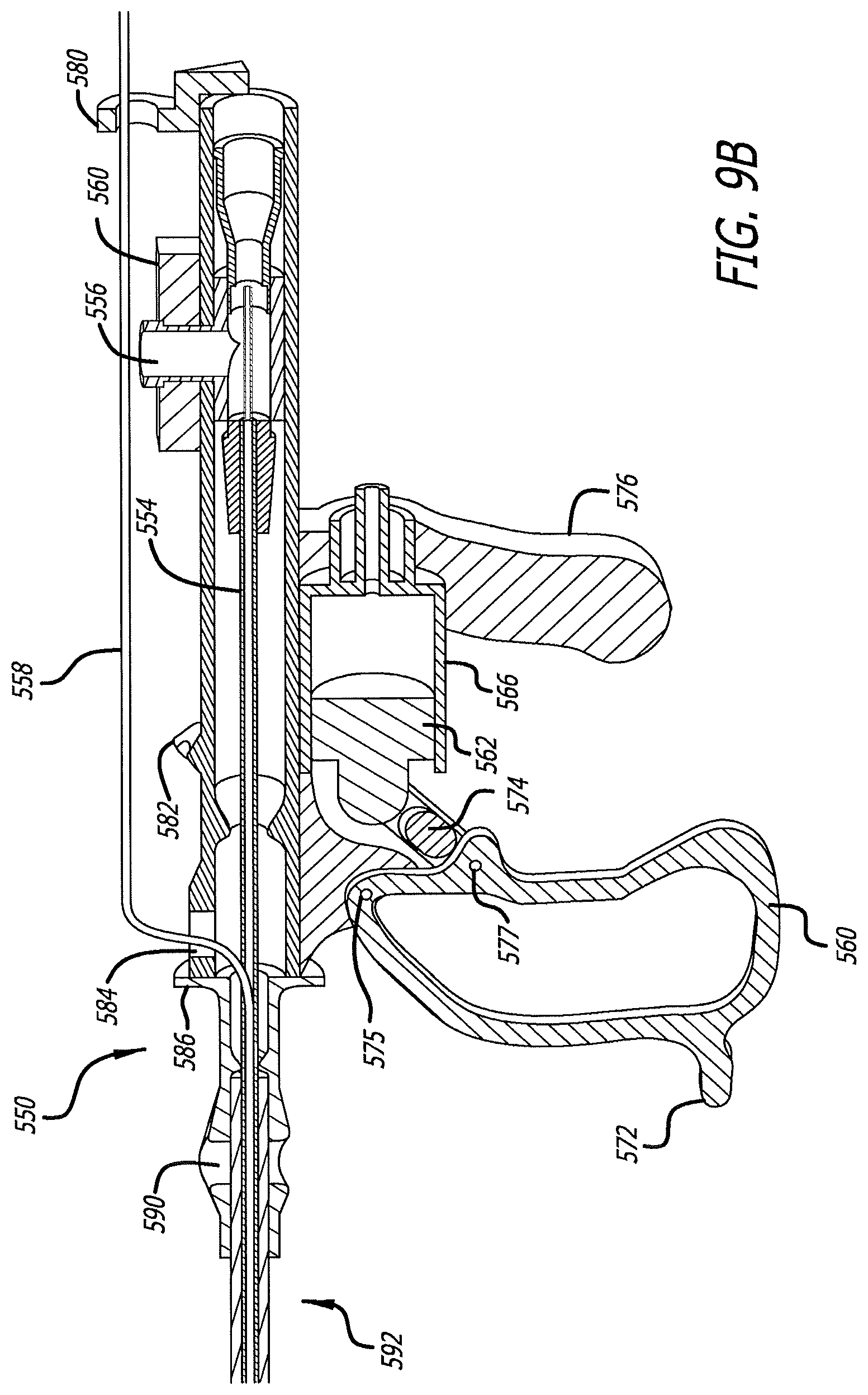
D00016

D00017

D00018

D00019

D00020

D00021

D00022

D00023

D00024

D00025

D00026

XML
uspto.report is an independent third-party trademark research tool that is not affiliated, endorsed, or sponsored by the United States Patent and Trademark Office (USPTO) or any other governmental organization. The information provided by uspto.report is based on publicly available data at the time of writing and is intended for informational purposes only.
While we strive to provide accurate and up-to-date information, we do not guarantee the accuracy, completeness, reliability, or suitability of the information displayed on this site. The use of this site is at your own risk. Any reliance you place on such information is therefore strictly at your own risk.
All official trademark data, including owner information, should be verified by visiting the official USPTO website at www.uspto.gov. This site is not intended to replace professional legal advice and should not be used as a substitute for consulting with a legal professional who is knowledgeable about trademark law.