Intra joint stabilization construct
Fallin , et al.
U.S. patent number 10,682,131 [Application Number 15/641,573] was granted by the patent office on 2020-06-16 for intra joint stabilization construct. This patent grant is currently assigned to CROSSROADS EXTREMITY SYSTEMS, LLC. The grantee listed for this patent is Mortise Medical, LLC. Invention is credited to T. Wade Fallin, Matthew Karam, Phinit Phisitkul, Justin Taber.
View All Diagrams
| United States Patent | 10,682,131 |
| Fallin , et al. | June 16, 2020 |
Intra joint stabilization construct
Abstract
The disclosure provides devices and methods of use pertaining to intra joint stabilization. Embodiments include a number of suture returning and suture locking anchors that feature elongated sleeves configured to protect the associated bone tunnels from suture wipering, which results in abrasion and enlargement of the bone tunnel and leads to migration of the suture anchors. Embodiments also include suture locking anchors that lock via an interference fit between the suture strand and a receiver of the anchor and a set screw, where the receiver and the set screw each feature a number of gradual, opposing tapers to facilitate gradual proximal-to-distal gripping and releasing of the suture strand to achieve an optimal locking force while preventing severing of the suture strand. Further embodiments include intra joint reinforcement and stabilization constructs formed using the disclosed devices. Other embodiments are disclosed.
| Inventors: | Fallin; T. Wade (Hyde Park, UT), Taber; Justin (Honolulu, HI), Karam; Matthew (North Liberty, IA), Phisitkul; Phinit (Coralville, IA) | ||||||||||
|---|---|---|---|---|---|---|---|---|---|---|---|
| Applicant: |
|
||||||||||
| Assignee: | CROSSROADS EXTREMITY SYSTEMS,
LLC (Memphis, TN) |
||||||||||
| Family ID: | 60892447 | ||||||||||
| Appl. No.: | 15/641,573 | ||||||||||
| Filed: | July 5, 2017 |
Prior Publication Data
| Document Identifier | Publication Date | |
|---|---|---|
| US 20180008255 A1 | Jan 11, 2018 | |
Related U.S. Patent Documents
| Application Number | Filing Date | Patent Number | Issue Date | ||
|---|---|---|---|---|---|
| 62358231 | Jul 5, 2016 | ||||
| 62425560 | Nov 22, 2016 | ||||
| 62456217 | Feb 8, 2017 | ||||
| 62458975 | Feb 14, 2017 | ||||
| Current U.S. Class: | 1/1 |
| Current CPC Class: | A61B 17/06166 (20130101); A61B 17/8869 (20130101); A61B 17/885 (20130101); A61B 17/0485 (20130101); A61B 17/1604 (20130101); A61B 90/06 (20160201); A61B 17/0401 (20130101); A61B 2017/0409 (20130101); A61B 2017/0441 (20130101); A61B 2017/0404 (20130101); A61B 2017/00526 (20130101); A61B 2090/061 (20160201); A61B 2017/0453 (20130101); A61B 2017/0464 (20130101); A61B 2017/0414 (20130101); A61B 2017/045 (20130101); A61B 2017/00867 (20130101); A61B 2017/0445 (20130101); A61B 2017/044 (20130101); A61B 17/848 (20130101); A61B 17/80 (20130101); A61B 2017/0403 (20130101) |
| Current International Class: | A61B 17/04 (20060101); A61B 90/00 (20160101); A61B 17/88 (20060101); A61B 17/16 (20060101); A61B 17/06 (20060101); A61B 17/80 (20060101); A61B 17/84 (20060101); A61B 17/00 (20060101) |
References Cited [Referenced By]
U.S. Patent Documents
| 2181746 | November 1939 | Siebrandt |
| 2291413 | July 1942 | Siebrandt |
| 2362957 | November 1944 | Hackett |
| 2427128 | September 1947 | Ettinger |
| 2485531 | October 1949 | William |
| 2489870 | November 1949 | William |
| 2511051 | June 1950 | William |
| 2706475 | April 1955 | Reynolds |
| 2715403 | August 1955 | Jordan |
| 3114367 | December 1963 | Carpenter |
| 3664022 | May 1972 | Small |
| 3727611 | April 1973 | Schultz |
| 3867932 | February 1975 | Huene |
| 3959960 | June 1976 | Santos |
| 4050464 | September 1977 | Hall |
| 4159716 | July 1979 | Borchers |
| 4364381 | December 1982 | Sher |
| D273326 | April 1984 | Peterson |
| 4586497 | May 1986 | Dapra |
| 4587963 | May 1986 | Leibinger |
| 4712542 | December 1987 | Daniel |
| 4787377 | November 1988 | Laboureau |
| 4945904 | August 1990 | Bolton |
| 4964862 | October 1990 | Arms |
| 4969471 | November 1990 | Daniel |
| 4969895 | November 1990 | McLeod |
| 5035701 | July 1991 | Kabbara |
| 5116340 | May 1992 | Songer |
| 5300077 | April 1994 | Howell |
| 5306290 | April 1994 | Martins |
| 5312410 | May 1994 | Miller |
| 5312412 | May 1994 | Whipple |
| 5409490 | April 1995 | Ethridge |
| 5431659 | July 1995 | Ross, Jr. |
| 5449361 | September 1995 | Preissman |
| 5476465 | December 1995 | Preissman |
| 5540698 | July 1996 | Preissman |
| 5545168 | August 1996 | Burke |
| 5570706 | November 1996 | Howell |
| 5578057 | November 1996 | Wenstrom, Jr. |
| 5584839 | December 1996 | Gieringer |
| 5643321 | January 1997 | McDevitt |
| 5713897 | February 1998 | Goble |
| 5725532 | March 1998 | Shoemaker |
| 5741281 | April 1998 | Martin |
| 5868748 | February 1999 | Burke |
| 5895389 | April 1999 | Schenk |
| 6001106 | December 1999 | Ryan |
| 6027523 | February 2000 | Schmieding |
| 6045573 | April 2000 | Wenstrom |
| 6254604 | July 2001 | Howell |
| 6254605 | July 2001 | Howell |
| 6368326 | April 2002 | Dakin |
| 6443955 | September 2002 | Ahrend |
| 6478753 | November 2002 | Reay |
| 6482208 | November 2002 | Ahrend |
| 6517564 | February 2003 | Grafton |
| 6527794 | March 2003 | McDevitt |
| 6547778 | April 2003 | Sklar |
| 6554852 | April 2003 | Oberlander |
| 6557426 | May 2003 | Reinemann, Jr. |
| 6616667 | September 2003 | Steiger |
| 6660023 | December 2003 | McDevitt |
| 6669698 | December 2003 | Tromanhauser |
| 6739068 | May 2004 | Rinner |
| 6761722 | July 2004 | Cole |
| 6780198 | August 2004 | Gregoire |
| 6866673 | March 2005 | Oren |
| 7060068 | June 2006 | Tromanhauser |
| 7081126 | July 2006 | McDevitt |
| 7083638 | August 2006 | Foerster |
| 7090690 | August 2006 | Foerster |
| 7160285 | January 2007 | Sklar |
| 7172626 | February 2007 | Andrews |
| 7211088 | May 2007 | Grafton |
| 7226469 | June 2007 | Benavitz |
| 7235091 | June 2007 | Thornes |
| 7326222 | February 2008 | Dreyfuss |
| 7431692 | October 2008 | Zollinger |
| 7442202 | October 2008 | Dreyfuss |
| 7455683 | November 2008 | Geissler |
| 7537596 | May 2009 | Jensen |
| 7556630 | July 2009 | Molz |
| 7572275 | August 2009 | Fallin |
| 7578824 | August 2009 | Justin |
| 7637926 | December 2009 | Foerster |
| 7871368 | January 2011 | Zollinger |
| 7875058 | January 2011 | Holmes, Jr. |
| 7887551 | February 2011 | Bojarski |
| 7901431 | March 2011 | Shurnas |
| 7963966 | June 2011 | Cole |
| 7998149 | August 2011 | Hamilton |
| 8083769 | December 2011 | Cauldwell |
| 8109936 | February 2012 | Tipirneni |
| 8114127 | February 2012 | West |
| 8114128 | February 2012 | Cauldwell |
| 8162997 | April 2012 | Struhl |
| 8167906 | May 2012 | Cauldwell |
| 8182495 | May 2012 | DiStefano |
| 8221455 | July 2012 | Shurnas |
| 8277459 | October 2012 | Sand |
| 8277484 | October 2012 | Barbieri |
| 8298247 | October 2012 | Sterrett |
| 8303591 | November 2012 | Foerster |
| 8317828 | November 2012 | Martinek |
| 8343186 | January 2013 | Dreyfuss |
| 8394123 | March 2013 | Cauldwell |
| 8414599 | April 2013 | Foerster |
| 8460379 | June 2013 | Albertorio |
| 8500745 | August 2013 | Kuenzi |
| 8506597 | August 2013 | Kaiser |
| 8579901 | November 2013 | Foerster |
| 8597328 | December 2013 | Cauldwell |
| 8613755 | December 2013 | Foerster |
| 8617185 | December 2013 | Bonutti |
| 8623049 | January 2014 | Ward |
| 8623051 | January 2014 | Bojarski |
| 8623052 | January 2014 | Dreyfuss |
| 8679122 | March 2014 | Bernstein |
| 8696719 | April 2014 | Lofthouse |
| 8715297 | May 2014 | Foerster |
| 8764763 | July 2014 | Foerster |
| 8764797 | July 2014 | Dreyfuss |
| 8790344 | July 2014 | Foerster |
| 8795286 | August 2014 | Sand |
| 8801755 | August 2014 | Dreyfuss |
| 8814902 | August 2014 | Bonutti |
| 8821541 | September 2014 | Dreyfuss |
| 8870876 | October 2014 | Lettmann |
| 8876900 | November 2014 | Guederian |
| 8882833 | November 2014 | Saylor |
| 8888815 | November 2014 | Holmes, Jr. |
| 8926626 | January 2015 | Mannava |
| 8939999 | January 2015 | Sterrett |
| 8945026 | February 2015 | Moser |
| 8961575 | February 2015 | Choinski |
| 8979850 | March 2015 | Johnstone |
| 8984720 | March 2015 | Gephart |
| 9017330 | April 2015 | Foerster |
| 9039682 | May 2015 | Lampropoulos et al. |
| 9072509 | July 2015 | Stoll, Jr. |
| 9107701 | August 2015 | Cole |
| 9131937 | September 2015 | Chan |
| 9138219 | September 2015 | Horrell |
| 9161748 | October 2015 | West |
| 9179907 | November 2015 | ElAttrache |
| 9179950 | November 2015 | Zajac |
| 9186133 | November 2015 | Gregoire |
| 9204872 | December 2015 | Loepke |
| 9259217 | February 2016 | Fritzinger |
| 9271715 | March 2016 | Cauldwell |
| 9277912 | March 2016 | Donate |
| 9521999 | December 2016 | Dreyfuss |
| 9526493 | December 2016 | Dreyfuss |
| 9532776 | January 2017 | Lo |
| 9549726 | January 2017 | Dreyfuss |
| 9622739 | April 2017 | Dreyfuss |
| 2001/0049483 | December 2001 | Reay |
| 2002/0087190 | July 2002 | Benavitz |
| 2002/0188297 | December 2002 | Dakin |
| 2003/0009171 | January 2003 | Tornier |
| 2003/0176920 | September 2003 | Sklar |
| 2004/0098045 | May 2004 | Grafton |
| 2004/0102788 | May 2004 | Huebner |
| 2004/0153153 | August 2004 | Elson |
| 2005/0065533 | March 2005 | Magen |
| 2005/0070906 | March 2005 | Clark |
| 2005/0222618 | October 2005 | Dreyfuss |
| 2005/0240226 | October 2005 | Foerster |
| 2006/0085006 | April 2006 | Ek |
| 2006/0161159 | July 2006 | Dreyfuss |
| 2006/0271060 | November 2006 | Gordon |
| 2006/0276804 | December 2006 | Molz |
| 2006/0293709 | December 2006 | Bojarski |
| 2007/0060922 | March 2007 | Dreyfuss |
| 2007/0060931 | March 2007 | Hamilton |
| 2007/0073299 | March 2007 | Dreyfuss |
| 2007/0083236 | April 2007 | Sikora |
| 2007/0088362 | April 2007 | Bonutti |
| 2007/0150003 | June 2007 | Dreyfuss |
| 2007/0198036 | August 2007 | Sklar |
| 2007/0225764 | September 2007 | Benavitz |
| 2007/0288027 | December 2007 | Grafton |
| 2008/0077182 | March 2008 | Geissler |
| 2009/0043153 | February 2009 | Zollinger |
| 2009/0228049 | September 2009 | Park |
| 2009/0306711 | December 2009 | Stone et al. |
| 2010/0010496 | January 2010 | Isaza |
| 2010/0160963 | June 2010 | Fallin |
| 2010/0191284 | July 2010 | Dreyfuss |
| 2010/0262185 | October 2010 | Gelfand |
| 2011/0022054 | January 2011 | DiStefano |
| 2011/0112576 | May 2011 | Nguyen |
| 2011/0184426 | July 2011 | Garces Martin |
| 2011/0224727 | September 2011 | Housman |
| 2012/0053626 | March 2012 | Koepke |
| 2012/0065677 | March 2012 | West |
| 2012/0123417 | May 2012 | Smith |
| 2012/0123428 | May 2012 | Berberich |
| 2012/0165867 | June 2012 | Denham et al. |
| 2012/0172936 | July 2012 | Horrell |
| 2012/0253410 | October 2012 | Taylor |
| 2013/0023930 | January 2013 | Stone et al. |
| 2013/0138150 | May 2013 | Baker |
| 2013/0165972 | June 2013 | Sullivan |
| 2013/0184708 | July 2013 | Robinson |
| 2013/0296937 | November 2013 | Dreyfuss |
| 2013/0345750 | December 2013 | Sullivan |
| 2014/0018828 | January 2014 | Foerster |
| 2014/0031882 | January 2014 | Schmuck |
| 2014/0039551 | February 2014 | Donahue |
| 2014/0074163 | March 2014 | West |
| 2014/0081322 | March 2014 | Sengun |
| 2014/0081323 | March 2014 | Hawkins |
| 2014/0081324 | March 2014 | Sengun |
| 2014/0081325 | March 2014 | Sengun |
| 2014/0114353 | April 2014 | Bojarski |
| 2014/0121701 | May 2014 | Dreyfuss |
| 2014/0128915 | May 2014 | Dreyfuss |
| 2014/0194907 | July 2014 | Bonutti |
| 2014/0194927 | July 2014 | Kaiser |
| 2014/0277134 | September 2014 | ElAttrache |
| 2014/0364905 | December 2014 | Lunn |
| 2014/0364909 | December 2014 | Dreyfuss |
| 2014/0371749 | December 2014 | Foerster |
| 2014/0379028 | December 2014 | Lo |
| 2015/0005779 | January 2015 | Tepic |
| 2015/0005819 | January 2015 | Dreyfuss |
| 2015/0012015 | January 2015 | Berelsman |
| 2015/0039029 | February 2015 | Wade |
| 2015/0051601 | February 2015 | Larsen |
| 2015/0073475 | March 2015 | Schaller |
| 2015/0073477 | March 2015 | Holmes, Jr. |
| 2015/0173739 | June 2015 | Rodriguez et al. |
| 2015/0201923 | July 2015 | Fan |
| 2015/0216576 | August 2015 | Foerster |
| 2015/0272567 | October 2015 | Feezor |
| 2015/0305737 | October 2015 | Conley |
| 2015/0313640 | November 2015 | O'Daly |
| 2015/0342594 | December 2015 | Stone |
| 2015/0342596 | December 2015 | Dreyfuss |
| 2015/0342651 | December 2015 | Cole |
| 2015/0351741 | December 2015 | Hawkins |
| 2016/0008041 | January 2016 | Makhlouf |
| 2016/0038201 | February 2016 | Cummings |
| 2016/0038267 | February 2016 | Allen |
| 2016/0051250 | February 2016 | Thornes |
| 2016/0051251 | February 2016 | Koepke |
| 2016/0066901 | March 2016 | Gregoire |
| 2016/0089131 | March 2016 | Wade |
| 2016/0192924 | July 2016 | Cauldwell |
| 2016/0235399 | August 2016 | Housman |
| 2016/0270902 | September 2016 | Snedeker et al. |
| 2016/0287302 | October 2016 | Horrell |
| 2016/0374661 | December 2016 | Housman et al. |
| 2017/0071592 | March 2017 | Feezor et al. |
| 551446 | Jan 1958 | CA | |||
| 132284 | Jan 1985 | EP | |||
| 2226791 | Apr 2005 | ES | |||
| 2002102236 | Apr 2002 | JP | |||
| 2011153417 | Dec 2011 | WO | |||
| 2012092027 | Jul 2012 | WO | |||
Other References
|
International Search Report and Written Opinion for Int. Appl. No. PCT/US2017/064173 dated Feb. 14, 2018, 8 pp. cited by applicant . International Search Report and Written Opinion for Int. Appl. No. PCT/US2017/064178 dated Mar. 9, 2018, 9 pp. cited by applicant . Akros Fibulink, Akros Medical, 2017, www.akrosmedical.com, 3 pp. cited by applicant . Deltoid Ligament Reconstruction Tunnel Sites, Arthrex, Inc., www.arthrex.com, 2014, 2 pp. cited by applicant . InternalBrace--Ligament Augmentaion Repair--Deltoid Ligament, Arthex, Inc., www.arthrex.com, 2015, 2 pp. cited by applicant . InternalBrace--Advanced Treatment for Ligament & Tendon Repair, Arthrex, Inc., www.arthrex.com, 2 pp. cited by applicant . InternalBrace--Ligament Augmentation Repair, Arthrex, Inc., www.arthrex.com, 2015, 2 pp. cited by applicant . Modified Brostrom-Gould Technique for Lateral Ankle Ligament Reconstruction--Surgical Technique, Arthrex, Inc., www.arthrex.com, 2015, 6 pp. cited by applicant . Knotless TightRope Syndesmosis Fixation--Surgical Technique, Arthrex, Inc., www.arthrex.com, 2015, 5 pp. cited by applicant . Get your athlete back in the game!--Syndesmosis TightRope, Arthrex, Inc., http://cptr.it/TRHAS, 2015, 1 pp. cited by applicant . ZipTight Fixation System, BioMet Sports Medicine, www.biometsportsmedicine.com, 2009, 8 pp. cited by applicant . Nelson, Owen A., "Examination and Repair of the AITFL in Transmalleolar Fractures", J. Orthop Trauma, vol. 20, No. 9, Oct. 2006, p. 637-643. cited by applicant . Invisiknot--Foot and Ankle Technique Guide--Ankle Syndesmosis Repair, Operative Technique, Smith & Nephew, Inc., www.smith-nephew.com, Jun. 2017, 8 pp. cited by applicant . Invisiknot--Ankle Syndesmosis Repair Kit, Smith & Nephew, Inc., www.smith-nephew.com, 1 pp. cited by applicant . Van Heest, Tyler J., et al., "Injureis to the Ankle Syndesmosis", J. Bone Joint Surg. Am. 2014;96:603-13, http://dx.dor.org/10.2106/JBJS.M.00094, 11 pp. cited by applicant. |
Primary Examiner: McEvoy; Thomas
Attorney, Agent or Firm: Meibos; David Maywood IP Law
Parent Case Text
REFERENCE TO PENDING PRIOR PATENT APPLICATIONS
This application claims the benefit under 35 U.S.C. 119(e) of U.S. Provisional Patent Application Nos. 62/358,231, filed Jul. 5, 2016 by Justin Taber and T. Wade Fallin for "LIGAMENT REINFORCEMENT DEVICES AND METHODS," 62/425,560 filed Nov. 22, 2016 by Justin Tabor, Phinit Phisitkul, and T. Wade Fallin for "LIGAMENT REINFORCEMENT DEVICES AND METHODS," 62/456,217, filed Feb. 8, 2017 by Justin Taber and T. Wade Fallin for "PLATE AND LOOP CONSTRUCT," and 62/458,975, filed Feb. 14, 2017 by Matthew Karam, Phinit Phisitkul, Justin Taber, and T. Wade Fallin for "PELVIC FRACTURE REPAIR," all of which patent applications are hereby incorporated herein by reference.
Claims
What is claimed is:
1. A method of at least one of reducing a joint or stabilizing bone, the method comprising: forming a first bone tunnel through a first bone; forming a second bone tunnel at least partially into a second bone; inserting a first anchor with a connected portion of a flexible synthetic strand through the first bone tunnel and into the second bone tunnel such that an end of the flexible synthetic strand extends out of the first bone tunnel; routing the end of the flexible synthetic strand through a second anchor comprising an axial hole and a receiver formed in a proximal portion of the second anchor, the receiver having internal threads extending over a proximal portion oriented at a proximal taper angle, a mid portion oriented at a mid taper angle, and a distal portion oriented at a distal taper angle; inserting the second anchor into the first bone tunnel; tensioning the flexible synthetic strand extending between the first and second anchors; and rotationally inserting a set screw into the receiver of the second anchor to lock the flexible synthetic strand relative to the second anchor, the set screw comprising external threads extending over a proximal portion oriented at an opposing proximal taper angle, a mid portion oriented at an opposing mid taper angle, and a distal portion oriented at an opposing distal taper angle, wherein: the proximal, the mid, and the distal taper angles of the receiver and the opposing proximal, the opposing mid, and the opposing distal taper angles of the set screw are configured such that the rotationally inserting the set screw into the receiver provides a gradual increase in a proximal compression force applied to the flexible synthetic strand extending between the proximal and the mid portions of the receiver and the set screw and a gradual decrease in a distal compression force applied to the flexible synthetic strand extending between the mid and the distal portions of the receiver and the set screw.
2. The method of claim 1, wherein the first bone and the second bone form a joint therebetween.
3. The method of claim 1, wherein at least one of the first anchor and the second anchor includes a polyaxial washer.
4. The method of claim 1, wherein the locking the flexible synthetic strand relative to the second anchor includes a reversible configuration so as to further allow unlocking the flexible synthetic strand relative to the second anchor.
5. The method of claim 1, wherein: the proximal taper angle of the receiver differs from the opposing proximal taper angle of the set screw; the mid taper angle of the receiver approximates the opposing mid taper angle of the set screw; and the distal taper angle of the receiver differs from the opposing distal taper angle of the set screw.
6. The method of claim 5, wherein the rotationally inserting the set screw into the receiver such that the mid portion of the set screw is positioned distal to a beginning of the mid portion of the receiver and an end of the mid portion of the set screw is positioned proximal to an end of the mid portion of the receiver provides first, second, third, fourth, and fifth zones of clearance between the set screw and the receiver, wherein the first zone provides a maximum proximal clearance between the set screw and the receiver, the third zone provides a minimum clearance between the set screw and the receiver and corresponds with a location at which the mid portions of the set screw and the receiver coincide to apply a maximum compression force to the flexible synthetic strand, and the fifth zone provides a maximum distal clearance between the set screw and the receiver.
7. A method of at least one of reducing a joint or stabilizing bone, the method comprising: forming a first bone tunnel through a first bone; forming a second bone tunnel through a second bone; inserting a first anchor with a connected portion of a flexible synthetic strand into the first bone tunnel and routing the flexible synthetic strand through the first and second bone tunnels such that an end of the flexible synthetic strand extends out of the second bone tunnel; routing the end of the flexible synthetic strand through a second anchor having a threaded receiver comprising a proximal portion, a mid portion, and a distal portion; inserting the second anchor into the second bone tunnel; tensioning the flexible synthetic strand extending between the first and second anchors; and locking the flexible synthetic strand relative to the second anchor by rotationally inserting a threaded set screw comprising a proximal portion, a mid portion, and a distal portion, into the threaded receiver, thereby achieving a progressively increasing interference fit about the flexible synthetic strand passing between the proximal portions and the mid portions of the threaded receiver and the threaded set screw and a progressively decreasing interference fit about the flexible synthetic strand passing between the mid portions and the distal portions of the threaded receiver and the threaded set screw.
8. The method of claim 7, wherein the first bone and the second bone form a joint therebetween.
9. The method of claim 7, wherein at least one of the first anchor and the second anchor includes a polyaxial washer.
10. The method of claim 7, further comprising rotationally removing the threaded set screw from the threaded receiver to unlock the flexible synthetic strand relative to the second anchor wherein the locking the flexible synthetic strand relative to the second anchor.
11. The method of claim 7, wherein: the threaded receiver comprises internal threads extending over the proximal portion oriented at a proximal taper angle, the mid portion oriented at a mid taper angle, and the distal portion oriented at a distal taper angle; the threaded set screw comprises external threads extending over the proximal portion oriented at an opposing proximal taper angle, the mid portion oriented at an opposing mid taper angle, and the distal portion oriented at an opposing distal taper angle; and the proximal, the mid, and the distal taper angles of the threaded receiver and the opposing proximal, the opposing mid, and the opposing distal taper angles of the threaded set screw are configured such that the rotationally inserting the threaded set screw into the threaded receiver provides a gradual increase in a proximal compression force applied to the flexible synthetic strand extending between the proximal and the mid portions of the threaded receiver and the threaded set screw and a gradual decrease in a distal compression force applied to the flexible synthetic strand extending between the mid and the distal portions of the threaded receiver and the threaded set screw.
12. The method of claim 11, wherein: the proximal taper angle of the threaded receiver differs from the opposing proximal taper angle of the threaded set screw; the mid taper angle of the threaded receiver approximates the opposing mid taper angle of the threaded set screw; and the distal taper angle of the threaded receiver differs from the opposing distal taper angle of the threaded set screw.
13. The method of claim 12, wherein the rotationally inserting the threaded set screw into the threaded receiver such that the mid portion of the threaded set screw is positioned distal to a beginning of the mid portion of the threaded receiver and an end of the mid portion of the threaded set screw is positioned proximal to an end of the mid portion of the threaded receiver provides first, second, third, fourth, and fifth zones of clearance between the threaded set screw and the threaded receiver, wherein the first zone provides a maximum proximal clearance between the threaded set screw and the threaded receiver, the third zone provides a minimum clearance between the threaded set screw and the threaded receiver and corresponds with a location at which the mid portions of the threaded set screw and the threaded receiver coincide to apply a maximum compression force to the flexible synthetic strand, and the fifth zone provides a maximum distal clearance between the threaded set screw and the threaded receiver.
Description
REFERENCE TO CO-FILED APPLICATIONS
This application was co-filed with the following U.S. patent application numbers on Jul. 5, 2017: 15/641,592, by Justin Taber and T. Wade Fallin for "EXTRA JOINT STABILIZATION CONSTRUCT,"; 15/641,600 by Justin Taber and T. Wade Fallin for "NONCIRCULAR BROACH AND METHODS OF USE,"; 15/641,618 by Phinit Phisitkul, Justin Taber, and T. Wade Fallin for "MULTIPLE SUTURE THREADER AND METHOD OF USE,"; and 15/642,053 by Justin Taber and T. Wade Fallin for "COMPRESSION AND TENSION INSTRUMENTS AND METHODS OF USE TO REINFORCE LIGAMENTS,"; all of which patent applications are incorporated herein by reference.
BACKGROUND
Ligaments interconnect bones of the skeletal system and are involved with the stabilization and kinematics of skeletal joints. Various injuries may occur that result in compromised ligament function. Such injuries include, for example, partial and complete tears and avulsion of the bone where a ligament attaches to a bone. Ligament injuries occur throughout the skeletal system.
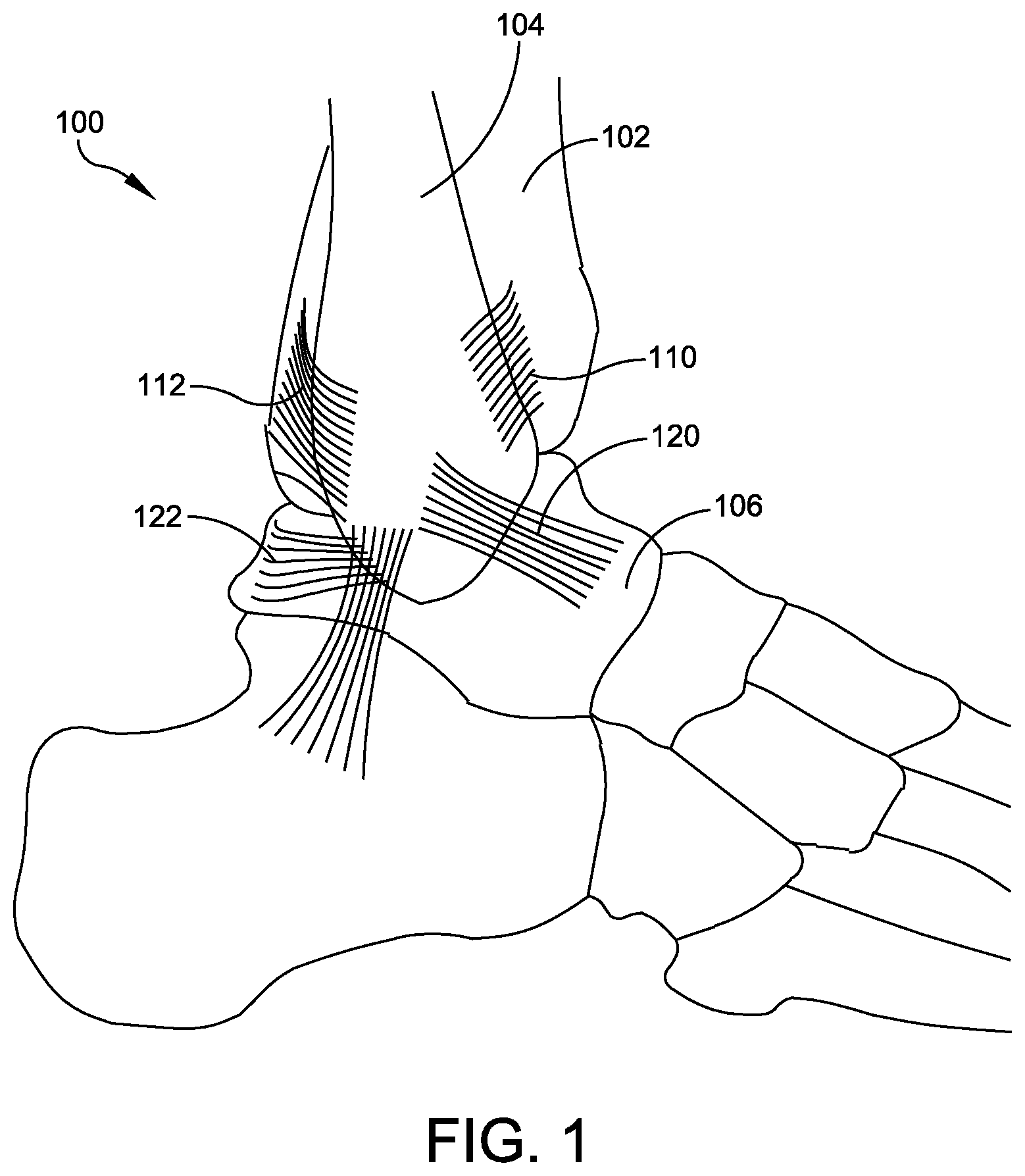
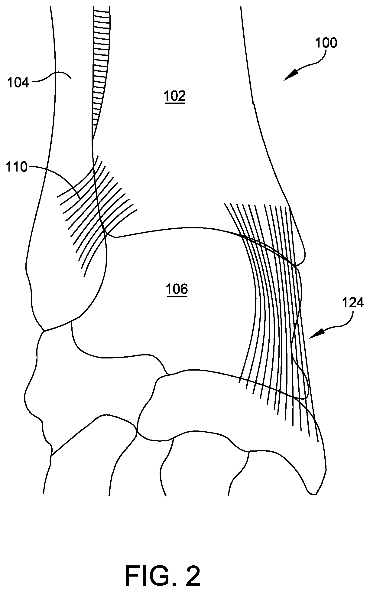
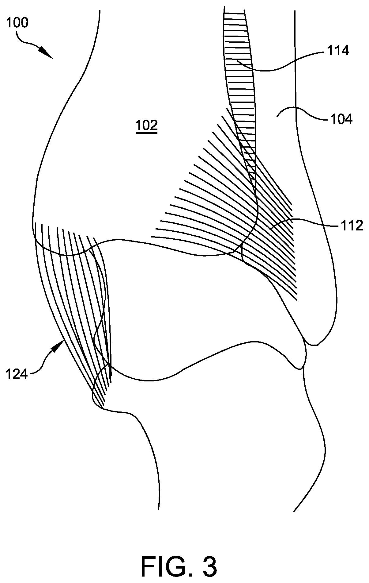
By way of example, the human ankle 100 is a complex junction of multiple bones and soft tissues as shown in FIGS. 1-3. The ankle includes joints between the tibia 102, fibula 104, and talus 106. The joint between the tibia 102 and fibula 104 is a syndesmosis or slightly movable joint in which the bones are joined together by connective tissue. The syndesmosis between the tibia and fibula includes the anterior inferior tibiofibular ligament (AITFL) 110, the posterior inferior tibiofibular ligament (PITFL) 112, and the interosseous ligament (IOL) 114 (FIG. 3). The syndesmosis ligaments are often injured in high ankle sprains. Other injury prone ligaments of the ankle joint include, among others, the anterior talofibular ligament (ATFL) 120, the posterior talofibular ligament (PTFL) 122 and the deltoid ligament complex 124 including superficial and deep deltoid ligaments. Current implants, instruments, and methods used to reinforce ligaments to promote healing and normal joint function present a number of challenges, and improvements are needed.
SUMMARY
This Summary is provided to introduce a selection of concepts in a simplified form that are further described below in the Detailed Description. This Summary is not intended to identify key aspects or essential aspects of the claimed subject matter. Moreover, this Summary is not intended for use as an aid in determining the scope of the claimed subject matter.
One embodiment provides an anchor for use in forming a flexible synthetic strand construct within a bone tunnel bored through a first bone portion, the bone tunnel having a first end adjacent to a first surface of the first bone portion and a second end near a second surface of the first bone portion. The anchor includes: (1) a head having a proximal side and a distal side, the distal side configured to abut the first surface of first the bone portion about the first end of the bone tunnel; (2) a longitudinal shank protruding distally from the head from a proximal end attached to the head to a distal end, the longitudinal shank defining a longitudinal axis and configured for insertion into the bone tunnel from the first end of the bone tunnel toward the second end of the bone tunnel, wherein: (a) an axial hole extends into the anchor along the longitudinal axis; (b) a length of the shank approximates a length of the bone tunnel; and (c) when, in passing from or to a separate strand fixation, a flexible synthetic strand enters or exits the axial hole at the distal end of the shank, the shank provides a bone tunnel protection sleeve that prevents transverse movement of the flexible synthetic strand relative to the bone tunnel, thereby preventing bone abrasion within the bone tunnel.
Another embodiment provides a knotless locking system for locking a flexible synthetic strand relative to a bone tunnel bored through a first bone portion, the bone tunnel having a first end adjacent to a first surface of the first bone portion and a second end near a second surface of the first bone portion. The locking system comprises a locking anchor and a set screw. The locking anchor includes: (1) a head; (2) a longitudinal shank protruding distally from the head, the shank having a proximal portion, a distal portion, and an axial hole extending therethrough, the shank defining a longitudinal axis and configured for insertion into the bone tunnel from the first end of the bone tunnel toward the second end of the bone tunnel; and (3) a receiver formed in the proximal portion of the shank, the receiver having internal threads extending over a proximal portion oriented at a proximal taper angle, a mid portion oriented at a mid taper angle, and a distal portion oriented at a distal taper angle. The set screw includes external threads extending over a proximal portion oriented at an opposing proximal taper angle, a mid portion oriented at an opposing mid taper angle, and a distal portion oriented at an opposing distal taper angle, wherein the proximal, the mid, and the distal taper angles of the receiver and the opposing proximal, the opposing mid, and the opposing distal taper angles of the set screw are configured such that when the set screw is rotationally inserted into the receiver, the set screw and the receiver provide a gradual increase in a proximal compression force applied to a length of the flexible synthetic strand extending between the proximal and the mid portions of the receiver and the set screw and a gradual decrease in a distal compression force applied to a length of the flexible synthetic strand extending between the mid and the distal portions of the receiver and the set screw.
Yet another embodiment provides an internal construct for stabilizing a joint between a first bone portion having a first bone tunnel that defines a longitudinal axis and a second bone portion having a second bone tunnel centered about the longitudinal axis. The internal construct comprises a flexible synthetic strand having first and second opposing ends tensioned between a first fixation within the first bone tunnel and a second fixation within the second bone tunnel, the first fixation comprising a locking anchor and a threaded set screw. The locking anchor includes (1) a head having a proximal side and a distal side, the distal side abutting a first surface of the first bone portion about a first end of the first bone tunnel; (2) a longitudinal shank protruding distally from the head, the shank having a proximal portion, a distal portion, and an axial hole extending therethrough, the shank inserted into the first bone tunnel from the first end of the first bone tunnel toward a second end of the first bone tunnel adjacent to the joint, the shank having a length that approximates a length of the first bone tunnel such that when the shank is inserted into the first bone tunnel, the distal portion of the shank extends to the second end of the first bone tunnel adjacent to the second surface of the first bone portion such that the shank provides a bone tunnel protection sleeve.
Additional objects, advantages and novel features of the technology will be set forth in part in the description which follows, and in part will become more apparent to those skilled in the art upon examination of the following, or may be learned from practice of the technology.
BRIEF DESCRIPTION OF THE DRAWINGS
Non-limiting and non-exhaustive embodiments of the present invention, including the preferred embodiment, are described with reference to the following figures, wherein like reference numerals refer to like parts throughout the various views unless otherwise specified. Illustrative embodiments of the invention are illustrated in the drawings, in which:
FIG. 1 illustrates a right view of a human ankle joint;
FIG. 2 illustrates a front view of a human ankle joint;
FIG. 3 illustrates a rear view of a human ankle joint;
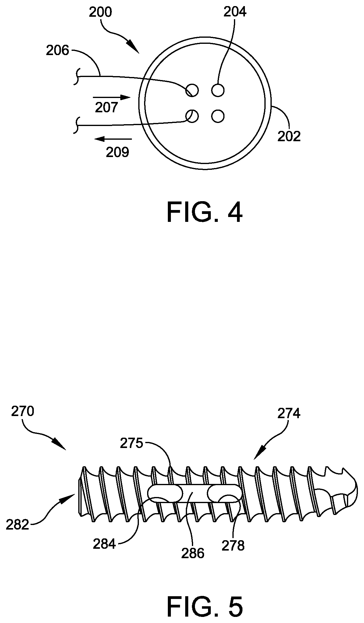
FIG. 4 illustrates a top view of one embodiment of button-like suture returning anchor;
FIG. 5 illustrates a side view of one embodiment of headless screw suture returning anchor;
FIGS. 6-12 illustrate various perspective, front, side, rear, and cross-sectional views of one embodiment of a polyaxial suture returning anchor;
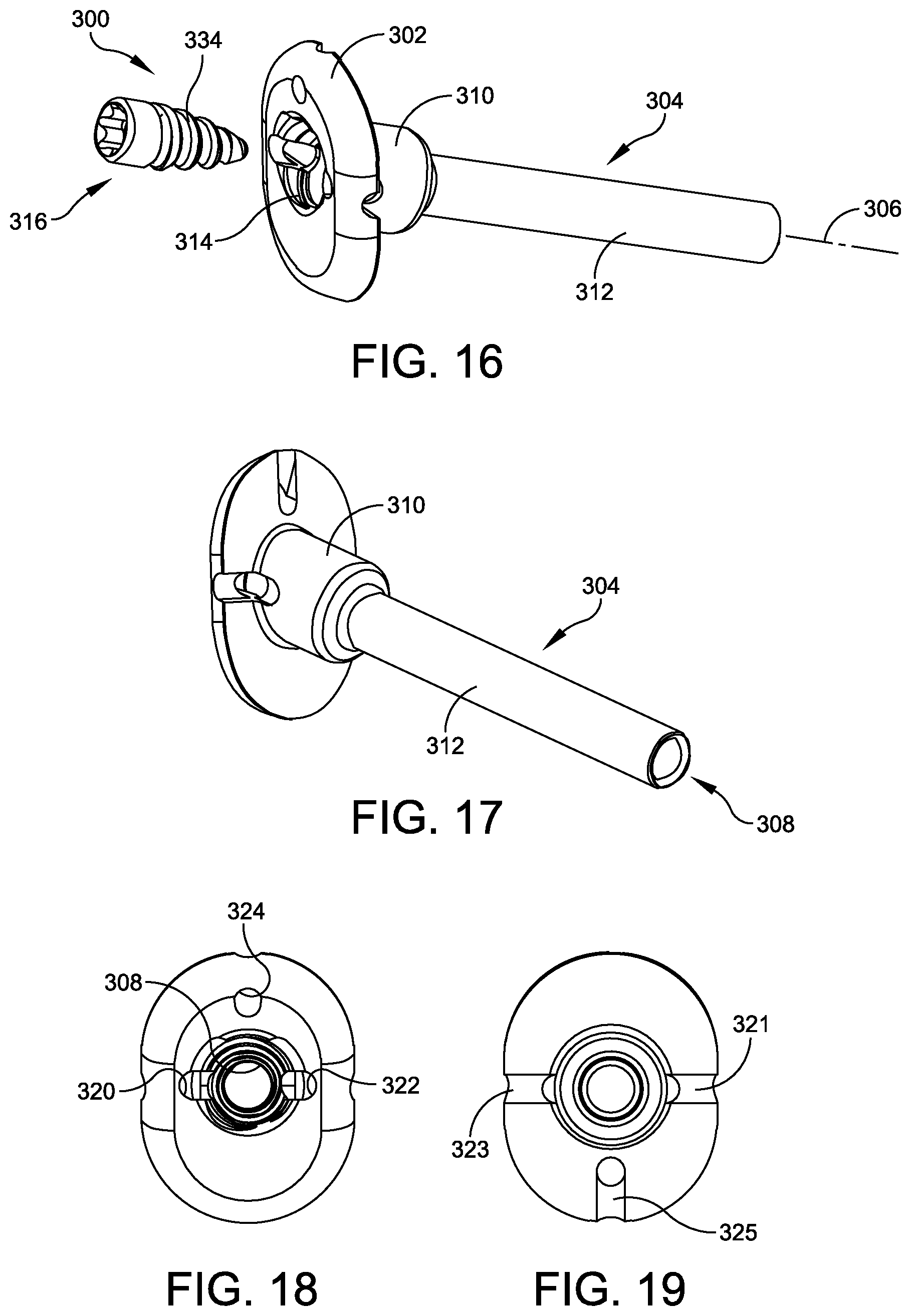
FIGS. 13-19 illustrate various perspective, front, side, rear, and cross-sectional views of one embodiment of a suture locking anchor;
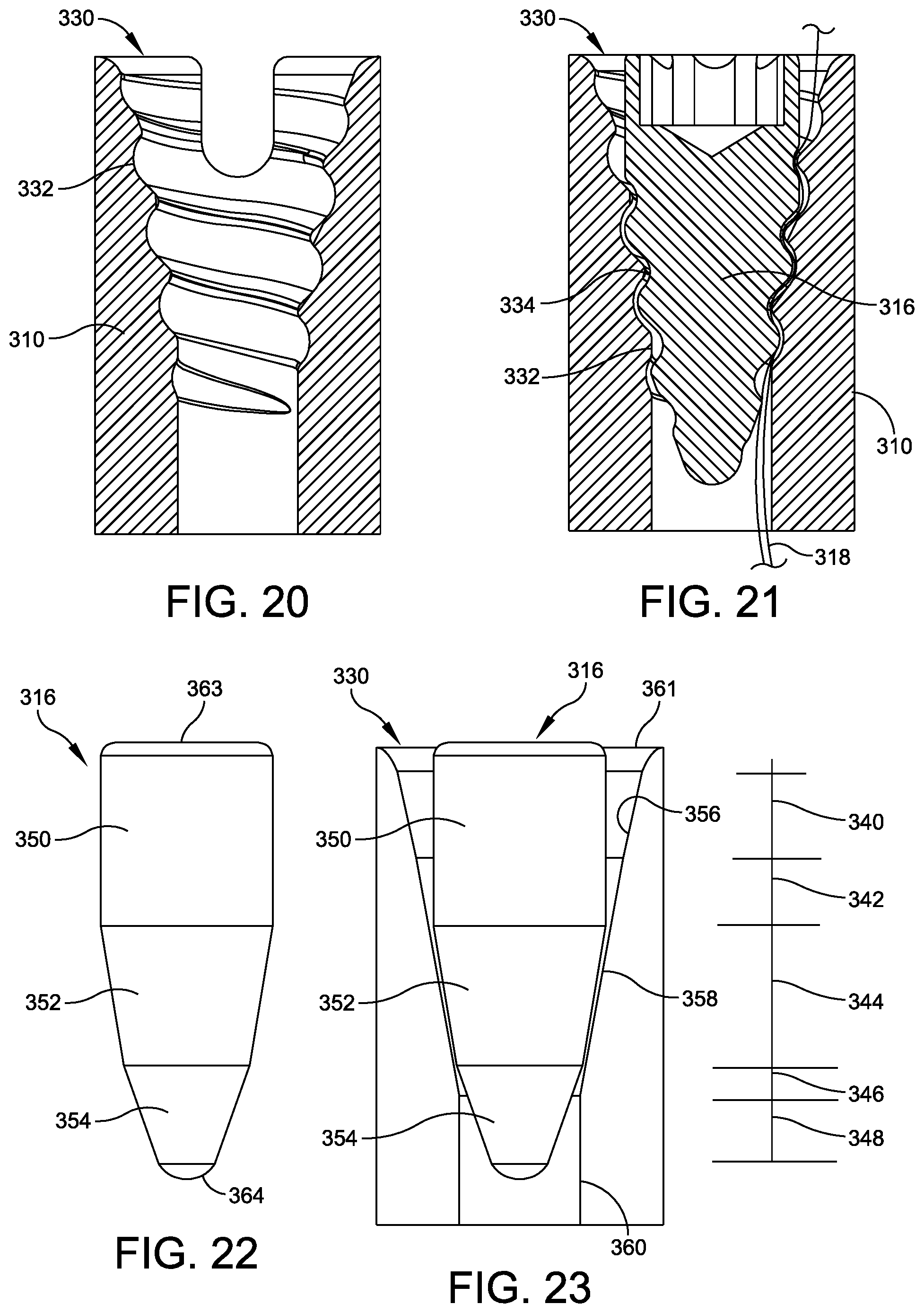
FIG. 20 illustrates a cross-sectional view of a receiver of a suture locking feature of the suture locking anchor of FIGS. 13-19;
FIG. 21 illustrates a cross-sectional view of the receiver of FIG. 20 having a set screw inserted therein to form an interference fit between a suture strand and the receiver and the set screw;
FIG. 22 illustrates a front view of the set screw of FIG. 21 without threading;
FIG. 23 illustrates the cross-sectional view of the set screw and the receiver of FIG. 21, without threading;
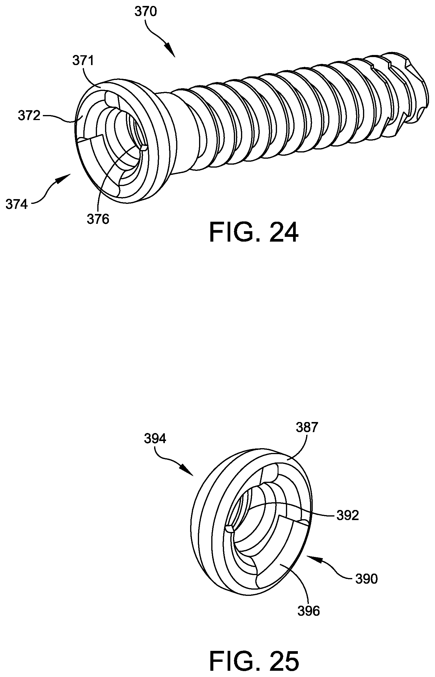
FIG. 24 illustrates a perspective view of one embodiment of a screw-type suture locking anchor having a countersunk head;
FIG. 25 illustrates a perspective view of one embodiment of a button-type suture locking anchor have a countersunk head;
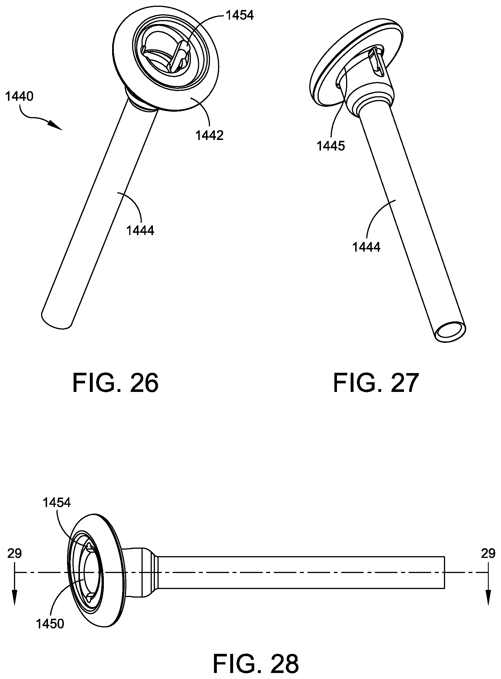
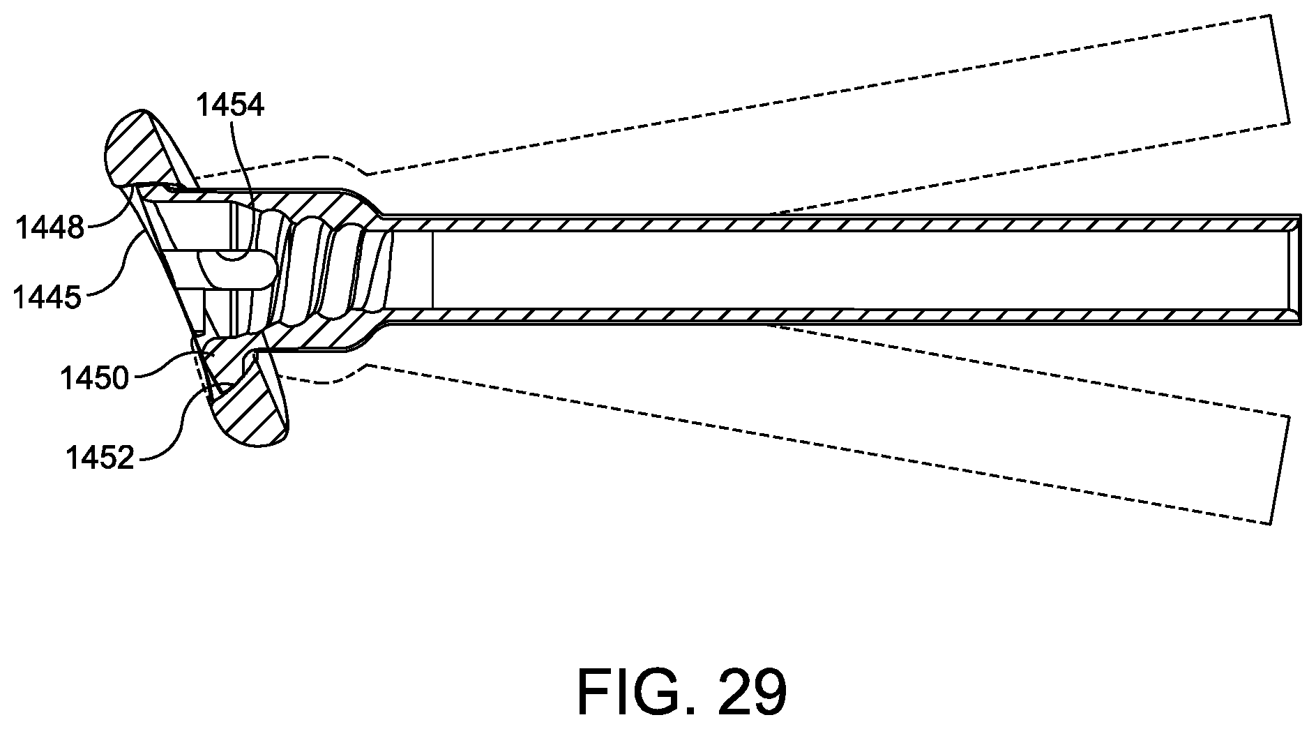
FIGS. 26-29 illustrate perspective, side, and cross-sectional views of one embodiment of a polyaxial suture locking anchor;
FIG. 30 illustrates an exploded view of one embodiment of a counter-torque anchor driver instrument in use with the suture locking anchor of FIGS. 13-19;
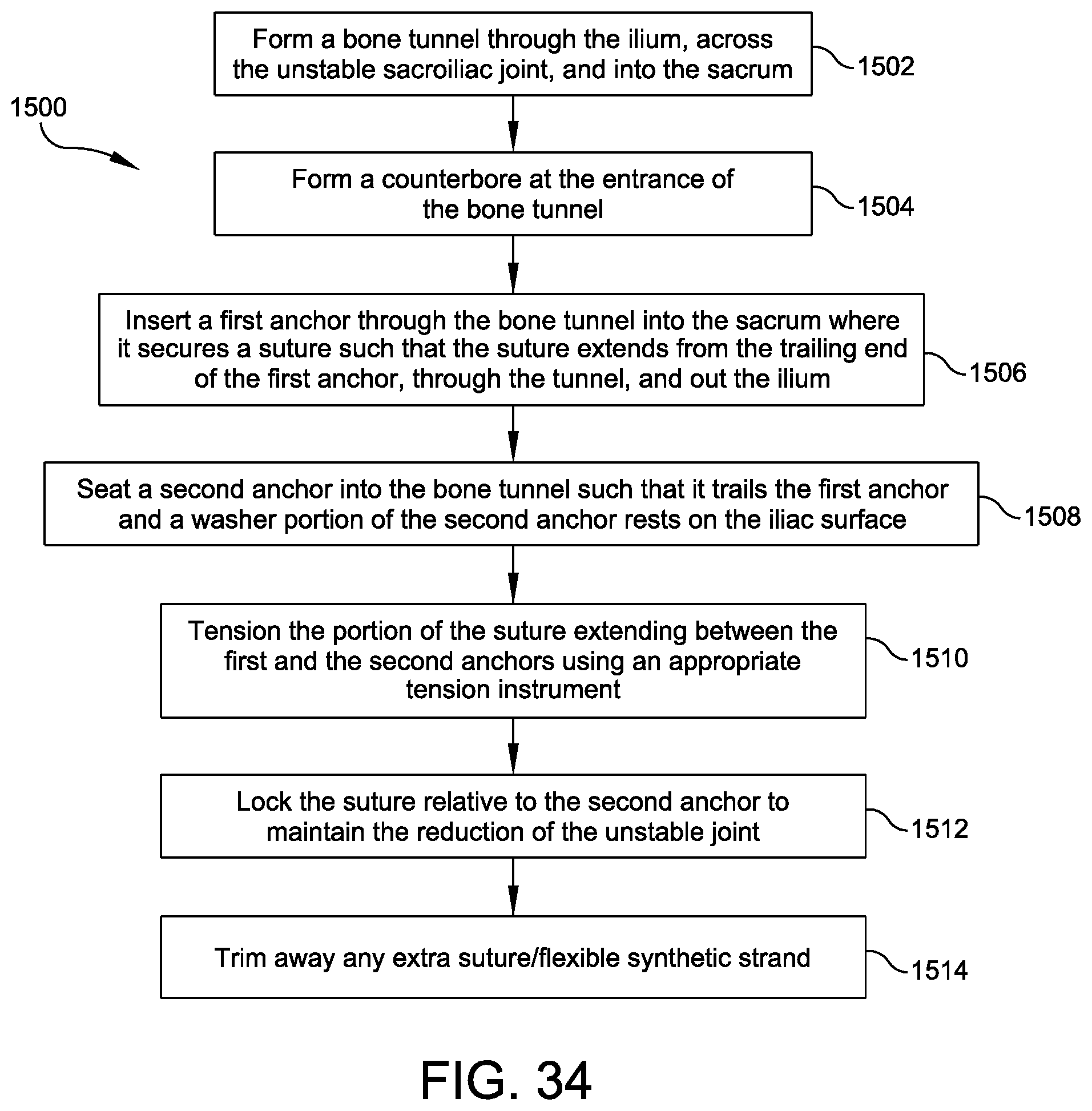
FIGS. 31-33 show partial sectional views through the sacrum parallel to the anatomic transverse plane of the pelvis and illustrate the steps of an operative sequence for reinforcing a sacroiliac fracture joint via a blind-hole bone tunnel using embodiments of the disclosed devices;
FIG. 34 provides a flowchart detailing the operative sequence illustrated by FIGS. 31-33;
FIG. 35 illustrates a side view of one embodiment of a syndesmosis reduction construct for an anterior inferior tibiofibular ligament (AITFL) using embodiments of the disclosed devices;
FIG. 36 provides a flowchart depicting an exemplary operative method for forming the syndesmosis reduction construct of FIG. 35;
FIG. 37 illustrates a side view of another embodiment of a syndesmosis reduction construct for an AITFL using embodiments of the disclosed devices and incorporating a bone plate;
FIGS. 38-40 provide graphic depictions of the syndesmosis reduction construct of FIG. 35, each figure showing progressively longer anchor sleeves that decrease a free span of suture extending between the sleeves;
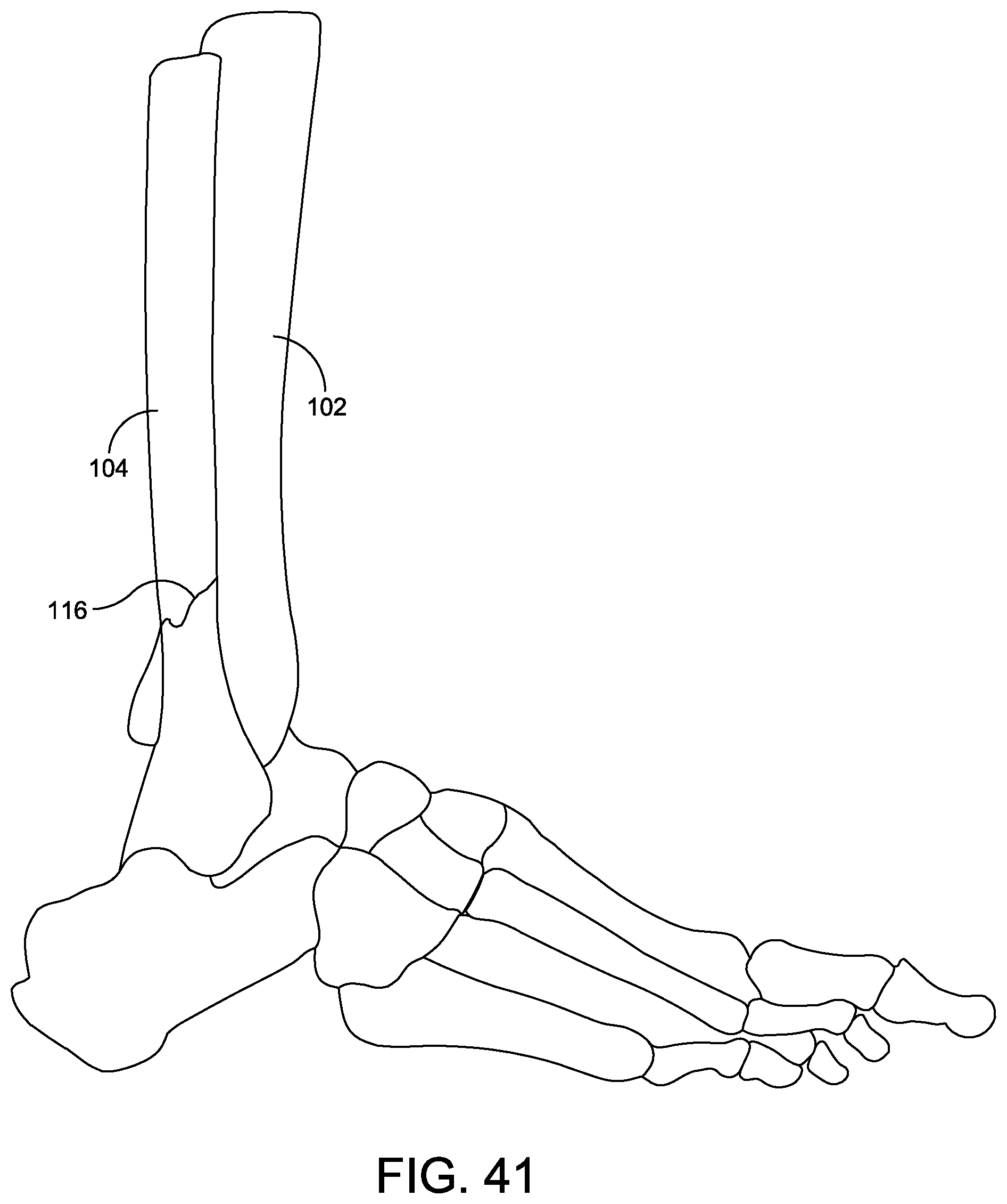
FIG. 41 illustrates a lateral view of a human ankle having a fracture of the fibular shaft;
FIG. 42-48 illustrate the steps of an operative sequence for a combined repair of the fibular fracture shown in FIG. 41 and a reinforcement of the syndesmosis joint between the tibia and fibula using embodiments of the disclosed devices;
FIG. 49 provides a flowchart detailing the operative sequence illustrated by FIGS. 42-48;
FIGS. 50-53 illustrate alternative steps of an operative sequence for forming a combined repair and reinforcement construct similar to that shown in FIG. 48; and
FIG. 54 provides a flowchart detailing the operative sequence illustrated by FIGS. 50-53.
DETAILED DESCRIPTION
Embodiments are described more fully below in sufficient detail to enable those skilled in the art to practice the system and method. However, embodiments may be implemented in many different forms and should not be construed as being limited to the embodiments set forth herein. The following detailed description is, therefore, not to be taken in a limiting sense.
The technology discussed herein relates to apparatus and corresponding methods of use for preparing ligament reinforcement and bone fracture repair constructs. Embodiments include a number of suture returning anchors, suture locking anchors, anchor locking drivers, bone protection sleeves, and intra joint ligament reinforcement and/or bone fracture repair constructs constructed via operative methods using the devices and instruments described herein.
The disclosed devices and/or constructs may be used in conjunction with and/or employ a flexible synthetic strand such as, for example, a suture, a suture tape, a cable, or another suitable flexible synthetic strand (hereinafter a "flexible strand," "flexible synthetic strand," or "suture").
Suture Returning Anchors
FIGS. 4-5 illustrate examples of suture returning anchors. In FIG. 4, a suture returning anchor 200 has a generally planar disc shaped body 202 in the form of a button with multiple holes 204 through the body 202. Suture 206 may be threaded through the holes 204 to secure the button to the suture. The suture 206 may be passed through a hole or tunnel in a bone such that the anchor 200 may then abut the surface of the bone adjacent the hole to prevent the suture from pulling through the hole. The anchor 200 is an example of a suture returning anchor because suture 206 may be threaded through one of the holes 204 in the anchor body in a first direction depicted by arrow 207 and then returned through another one of the holes 204 in a second, opposite direction depicted by arrow 209 such that ends of the suture 206 are provided together extending away from the anchor 200 on a common side of the anchor 200.
A suture returning anchor may be used, for example, when a suture from another portion of a reinforcement procedure needs to be anchored and tensioned using an approach from one side of the bone. The suture may have a first end fixed to another fixation structure and a second free end. The second end may be threaded through a suture returning anchor and returned so that pulling on the second end tensions the reinforcement construct. A suture returning anchor may also be used to supply two ends or a loop of suture that will be tensioned without sliding through the implant.
FIG. 5 illustrates another embodiment of a suture returning anchor 270 in the form of a headless screw that includes a shank 274 having an external spiral screw thread 275. The shank 274 includes a distal first transverse hole 278, an axial hole 282 opening at a proximal end of the shank 274, a second transverse hole 284, and relief grooves 286. A suture may be threaded into the axial hole 282 from the proximal end, out one of the openings of the second transverse hole 284, through the first transverse hole 278, in the other one of the openings of the second transverse hole 284, and out the axial hole 282 so that the suture is routed within the proximal portion of the shank. The relief grooves 286 may connect the openings of the first and the second transverse holes 278, 284 on each side of the shank 274. The relief grooves 286 allow a suture to pass from the axial hole 282 to the first transverse hole 278 while projecting less, or not at all, from an outer wall of the shank 274 to protect the suture from abrasion and to allow the suture to slide more easily while it is being routed and tensioned. A driver may be received in the axial hole 282 for driving the screw into a bone.
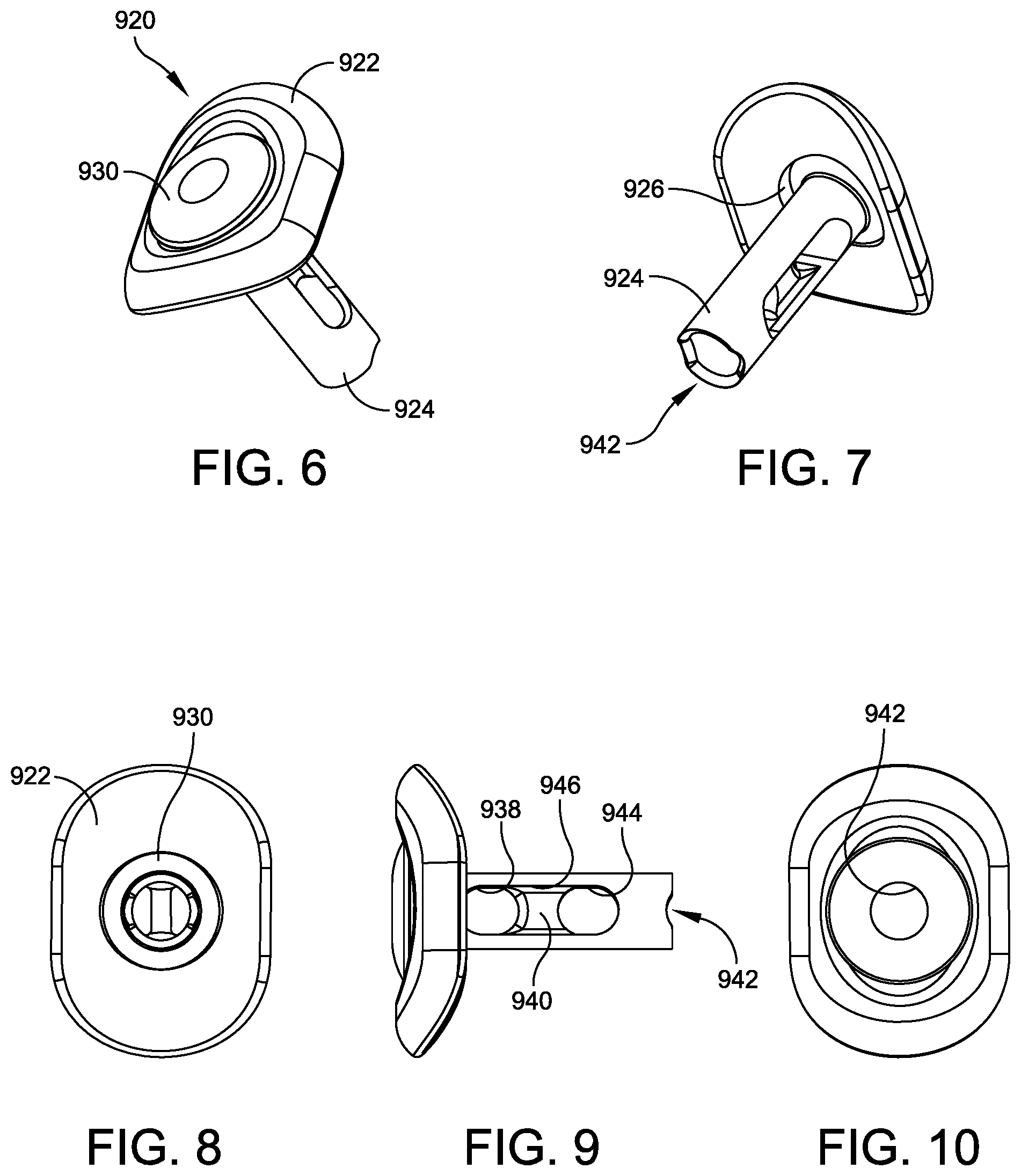
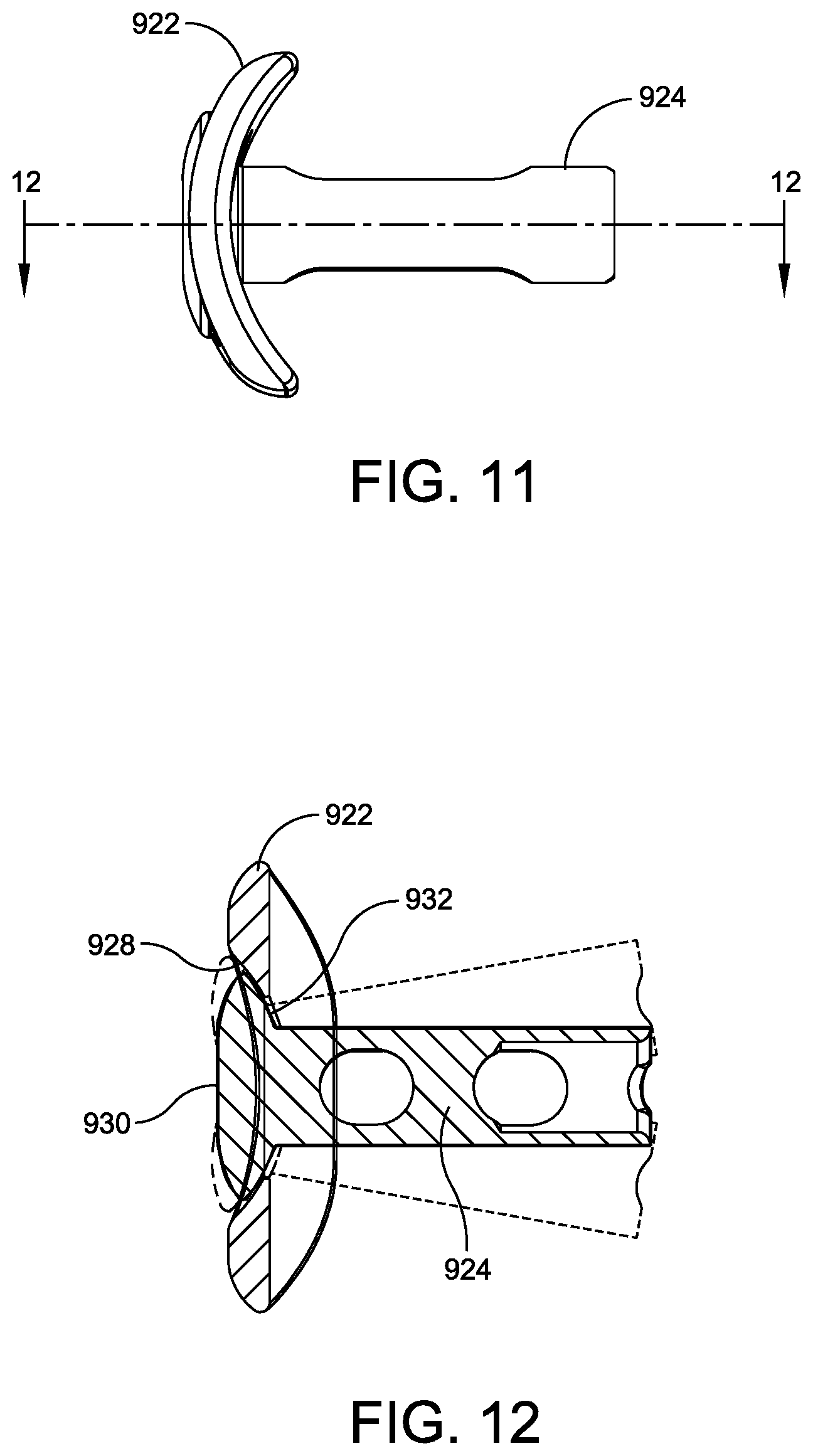
FIGS. 6-12 illustrate an example of a polyaxial suture returning anchor 920. In this embodiment, the anchor 920 is a two-piece anchor having a separate washer 922 and shank 924. The shank 924 extends from a proximal end at the washer 922 to a distal end spaced from the washer 922 and includes one or more transverse holes through which a suture, or flexible synthetic strand, may be threaded. In this embodiment, the shank 924 includes a first transverse hole 938 forming opposed openings on opposite sides of the shank 924 through which a suture may be threaded to provide a suture return. While the washer 922 abuts a bone, a suture may be pulled against a distal margin 940 of the hole to allow the suture to be tensioned. The shank further includes an axial hole 942 extending from an opening at its distal end toward its proximal end. A second transverse hole 944 extends through the shank 924 to form opposed openings on opposite sides of the shank 924 and which is offset distally from the first transverse hole. The second transverse hole 944 communicates with the axial hole 942.
A suture may be threaded into the axial hole 942 from the distal end, out one of the openings of the second transverse hole 944, through the first transverse hole 938, in the other of the openings of the second transverse hole 944, and out the axial hole 942 so that the suture is routed within the distal portion of the shank 924. The anchor shank 924 may further contain relief grooves 946 connecting the openings of the first and second transverse holes 938, 944 on each side of the shank 924. The relief grooves allow the suture to pass from the axial hole 942 to the first transverse hole 938 while projecting less, or not at all, from the shank sides to protect the suture from abrasion and to allow the suture to slide more easily while it is being routed and tensioned.
In the example of FIGS. 6-12 the washer 922 includes a hole 926 formed through it and a spherical seat 928 formed adjacent the hole 926. The shank 924 has a head 930 with a spherical seat 932 on its undersurface, adjacent the shank. The spherical seats 928 and 932 engage and permit the washer 922 to assume a range of angles relative to the shank 924 so that when the shank 924 is inserted into a tunnel in a bone and advanced so that the washer 922 is abutting the bone surface, the washer can angulate to match the angle between the bone tunnel and the bone surface. The adjustable polyaxial relationship between the shank 924 and the washer 922 permits the washer 922 to lie close to the bone in a low-profile manner.
Suture Locking Anchors
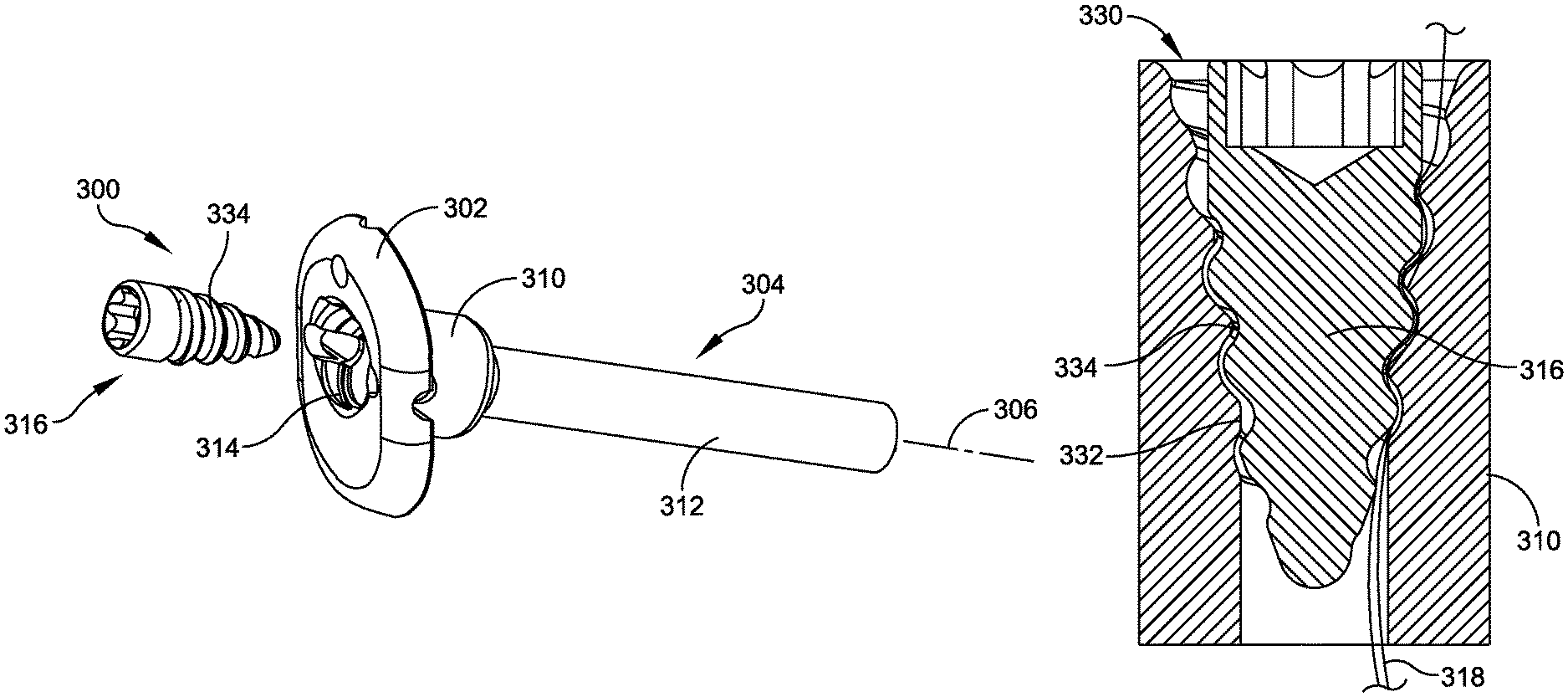
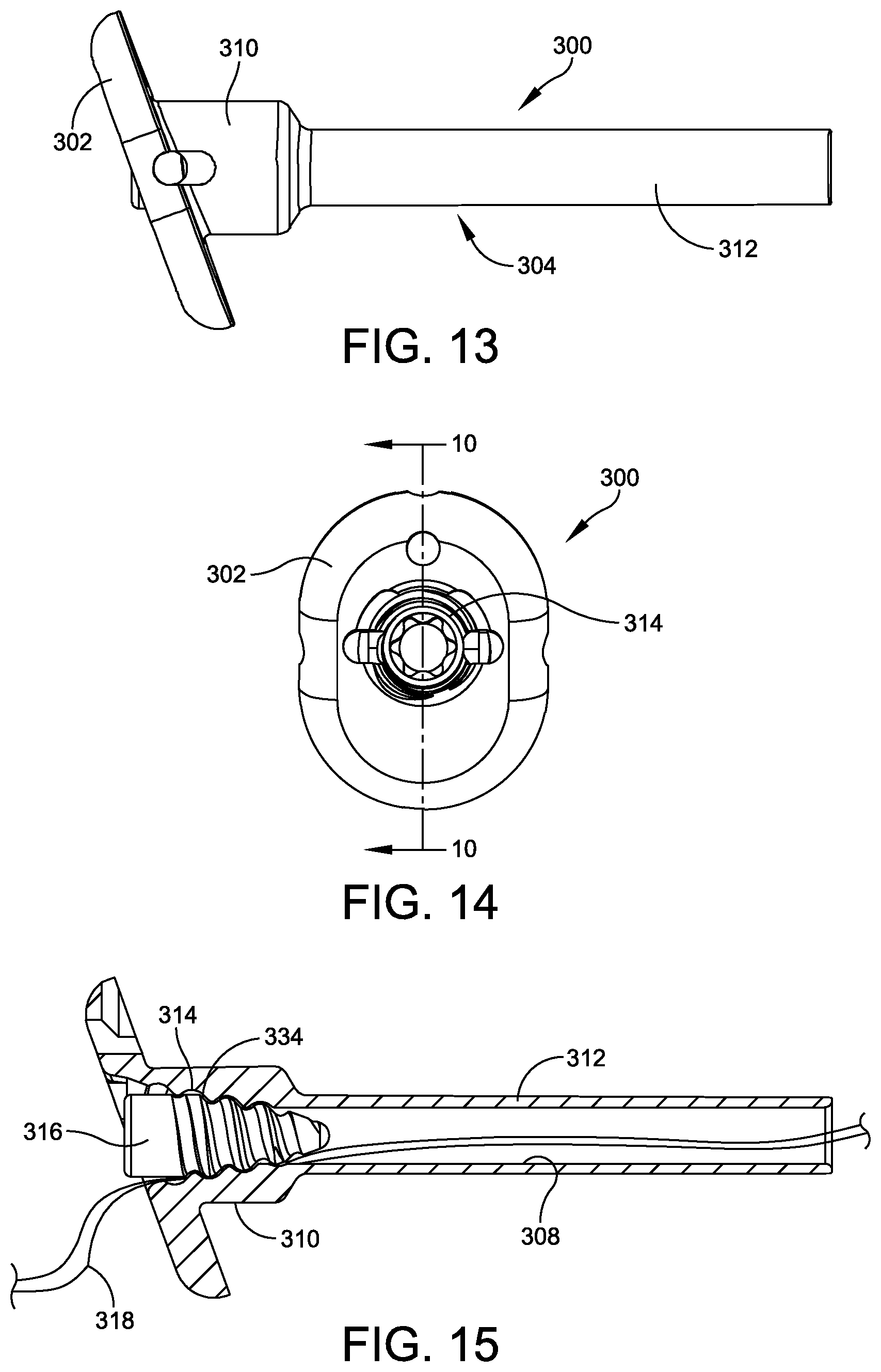
FIGS. 13-30 illustrate examples of suture locking anchors. FIGS. 13-19 illustrate a number of views of a suture locking anchor 300, which has a button-like head 302 and a stepped cylindrical shank 304 projecting outwardly from a distal side of the head 302 and defining a longitudinal axis 306. An axial hole 308 extends through the anchor 300. A proximal portion 310 of the shank has a larger diameter than a distal portion 312 of the shank 304. The proximal portion 310 includes internal threads 314 configured to receive external threads 334 of a set screw 316 to lock a suture within the axial hole 308.
In use, one or more sutures 318 or other flexible synthetic strands may be threaded through the axial hole 308, tensioned, and then locked in place by inserting the set screw 316 to create an interference engagement between the suture 318, the threads 334 of the set screw 316, and the threads 314 of the proximal portion 310 of the shank 304.
In the example of FIGS. 13-19, the head 302 is mounted at a non-perpendicular angle relative to the shank 304 to accommodate a suture path through a bone that is at a non-perpendicular angle to a surface of the bone against which the head 302 abuts. In this embodiment, the head 302 further includes supplemental suture holes 320, 322, 324 extending through the head 302 proximally-to-distally to allow additional sutures to be threaded through the head 302. Relief grooves 321, 323, 325 are provided on the distal surface of the head 302 and in communication with the supplemental suture holes 320, 322, 324 to provide relief for the additional sutures between the head 302 and the underlying bone.
In the example of FIGS. 13-19, the head 302 is generally oval shaped and presents a smooth surface to overlying soft tissues to reduce irritation of soft tissues. The shank 304 provides a tubular extension into a bone tunnel to protect the suture from abrasion from the bone as well as to protect the bone tunnel from abrasion or cutting from the suture.
Traditional button-style locking anchors sit on an exterior of the bone at an end of the bone tunnel and are locked via a suture knot that is tied off at the surface of the button, positioning the knot in a manner that irritates the surrounding soft tissues. Over time, the suture erodes the bone at the bone tunnel exit, and the button tends to sink or subside into the bone. Physicians have recorded up to 10 mm of migration of the button into the bone. As the bone degrades and the suture loosens, the button also develops a level of back-and-forth translational movement at the surface of the bone, which irritates both the bone and the surrounding tissues.
Embodiments of the suture locking anchor 300 avoid these complications. The shank 304 extends into a tightly fitted bone tunnel such that the shank 304 is press fit into the cortex, or the hard exterior shell, of the bone. This increased amount of surface area between the shank and the bone cortex, as well as the protective sheath the shank 304 and the head 302 provide to the suture 318 at the bone's surface and the knotless locking mechanism, serve to anchor the implant and prevent the head 302 from cutting or subsiding into the bone tunnel, resulting in a more stable, longer lasting reinforcement construct. Any extra suture length 318 is completely trimmable such that the resulting suture is flush with the anchor head 302 and locked set screw 316, further preventing tissue irritation.
FIGS. 20-23 illustrate the details of the suture locking feature of the example of FIGS. 13-19. FIG. 20 provides an enlarged view of the features of the internal portion of the proximal portion 310 of the shank 304, and FIG. 21 provides a cross-sectional view of the proximal portion 310 of the shank 304 in receipt of the set screw 316. The proximal portion 310 of the shank has a receiver 330 having a tapered receiver thread 332, and the set screw 316 has a tapered external thread 334. Both the receiver thread 332 and the set screw thread 334 are rounded knuckle threads. In addition, the receiver 330/receiver thread 332 and the set screw 316/set screw thread 334 feature multiple discrete taper angles that transition proximally to distally to provide for progressive gripping and releasing of the suture 318 to provide a strong grip on the suture while reducing the risk of suture damage.
To address the taper angles in greater detail, FIGS. 22-23 illustrate the set screw 316 and the receiver 330 without their knuckle threading to better illustrate the gradual transitions of their tapers. The set screw 316 is cylindrical at a proximal portion 350, has a relatively small angled taper over its mid portion 352, and has a relatively large angled taper over its distal portion 354 which terminates in a rounded tip 364. The receiver 330 has a relatively large angled taper at a proximal portion 356, has a relatively small angled taper over its mid portion 358, and is cylindrical at its distal portion 360. When the set screw 316 and the receiver 330 are mated, they provide progressively less clearance between them from the proximal end of the anchor 300 to their mid portions and progressively more clearance between them from their mid portions distally to the end of the set screw 316.
This opposing tapered configuration of the set screw 316 versus the receiver 330 incorporates the principal of the Morse taper for mating components. The opposing conical shapes of the set screw 316 and the receiver 330 are closely matched or approximated in taper angle at their mid portions 352, 358, while the opposing shapes of the set screw 316 and the receiver 330 differ in taper angle at their proximate portions 350, 356 and their distal portions 354, 360. This arrangement causes the respective surfaces of the set screw 316 and the receiver 330 to achieve an interference fit about the suture 318 over the mid portions 352, 358 of the set screw 312 and the receiver 330, with gradual transitions proximally leading into and distally leading out of the interference fit. This gradual transition of compression forces applied to the suture 318 disposed between the set screw 316 and the receiver 330 leads to an enhancement in suture fixation/locking strength, and simultaneously reduces the risk of severing the suture 318 that is present with greater magnitudes of compression force transition.
In one embodiment, the mid portions 352, 358 of the set screw 316 and the receiver 330 are of the same length and aligned. In this embodiment, there are three zones or amounts of clearance between the set screw 316 and the receiver 330 progressing in three steps from a relatively large amount of clearance proximally to a relatively small amount of clearance over their mid portions to a relatively large amount of clearance distally.
In an alternate embodiment, and as shown in the example of FIGS. 20-23, the set screw 316 can be driven so that the beginning of its mid portion 352 is positioned distal of the beginning of the receiver mid portion 358, and the end of the set screw mid portion 352 is positioned proximal of the end of the receiver mid portion 358, as shown in FIG. 23. This arrangement results in five clearance zones 340, 342, 344, 346, and 348 for an even more gradual progression of gripping and releasing of the suture 316. Any number of taper angle steps may be provided on the set screw 316 and the receiver 330, and any arrangement of overlap or radius blending may be provided to produce any number of progressive clearance steps to transition proximally to distally from no grip to maximum grip to no grip on the suture, protecting the suture through the gradual increase and decrease of stress placed on the suture 318.
Referring to FIG. 23, the first zone 340 provides a maximum clearance proximally and the clearance decreases distally at the angular difference between the cylindrical proximal portion 350 of the set screw 316 and the relatively larger angle of the proximal portion 356 of the receiver 330. The second zone 342 clearance decreases distally at the angular difference between the cylindrical proximal portion 350 of the set screw 316 and the relatively smaller angle of the mid portion 358 of the receiver 330. The third zone 344 provides the least clearance and corresponds to where the mid portions 352, 358 of the set screw 316 and the receiver 330 coincide. The fourth zone 346 clearance increases distally at the angular difference between the relatively smaller angle of the mid portion 358 of the receiver 330 and the relatively larger angle of the distal portion 354 of the set screw 316. The fifth zone 348 provides the most clearance distally and the clearance increases distally at the angular difference between the relatively larger angle of the distal portion 354 of the set screw 316 and the cylindrical portion 360 of the receiver 330.
In the illustrative example of FIGS. 20-23, the set screw 316 taper is cylindrical in the first proximal portion 350, 10 degrees per side in the second mid portion 352, and 20 degrees per side in the distal portion 354. The receiver 330 taper is 20 degrees per side in the first proximal portion 356, 10 degrees per side in a second mid portion 358, and cylindrical at a third distal portion 360. The resulting relief tapers corresponding to the five zones 340, 342, 344, 346, 348 illustrated in FIG. 23, proximally to distally, are 20 degrees, 10 degrees, 0 degrees, 10 degrees, and 20 degrees. In this embodiment, the proximal ends 361, 363 of the receiver 330 and the set screw 316 are chamfered and the distal end 364 of the set screw 316 is rounded to further eliminate any sharp edges to further smooth the path of the suture and to provide easier starting of the screw.
While the embodiment of FIGS. 20-23 features opposing tapers on the set screw 316 and the receiver 330, it should be understood that the invention contemplates any appropriate tapering configuration that provides a gradual increase and decrease of compression forces applied, proximally to distally, to the interference fit of the suture 318 between the set screw 316 and the receiver 330. For example, the set screw 316 may be entirely cylindrical through its proximal, mid, and distal portions, maintaining the above described configuration of the receiver 330. In another example, the proximal, mid, and distal portions 350, 352, 354 of the set screw 316 may be angled to form an egg-like or football shape, while the proximal, mid, and distal portions 356, 358, 360 of the receiver 330 remain cylindrical.
The locking feature discussed in relation to FIGS. 20-23 provides both a knotless and reversible mechanism for locking out the suture 318 relative to the locking anchor 300. Because an interference fit between the suture 318, the set screw 316, and the receiver 330 provides the compression force required to secure the suture 318 in tension relative to the anchor 300, the locking feature provides a knotless fixation, thereby reducing the probability of bone and/or tissue abrasion and/or aggravation that is often caused by knotted fixations. Moreover, because the locking mechanism protects the integrity of the suture through the gradual increase and decrease of stress placed on the suture 318, as discussed above, the knotless fixation is truly reversible in that the set screw 316 may be rotationally inserted to lock out the suture 318 relative to the anchor 300 without damaging the suture 318 and/or risking its structural integrity. As a result, a surgeon may lock and unlock the suture 318 relative to the anchor 300 multiple times to achieve an optimal fixation while maintaining confidence in the quality of the ultimate knotless fixation.
FIGS. 24-25 illustrate additional examples of suture locking anchors incorporating the tapered, knuckle-threaded suture-locking arrangement of FIGS. 20-23. In FIG. 24, an anchor 370 in the form of a bone screw has a proximal head 371 with an internal driver feature 372, an axial through hole 374, and a tapered threaded receiver 376 for receiving a set screw 316 like that shown in FIG. 21. FIG. 25 illustrates a suture locking anchor 394 in the form of a button with a proximal head 387 operable to seat in a spherical countersink in a bone plate. The anchor 394 includes an internal driver feature 396, and axial hole 390, and a tapered threaded receiver 392 for receiving a set screw like that shown in FIG. 25. Each of the respective proximal heads 371, 387 of the anchors 370, 394 may be countersunk such that they are configured to seat within, and reside flush with a surface of, a bone plate positioned upon and anchored to either the tibia 102 or the fibula 104 (FIGS. 1-3).
FIGS. 26-29 illustrate an example of a polyaxial suture locking anchor 1440 similar to the anchor 300 of FIG. 16. However, the anchor of the example of FIGS. 26-29 is a two-piece anchor having a separate washer 1442 and shank 1444. The washer has a hole 1445 formed through it and a spherical seat 1448 formed adjacent the hole. The shank 1444 has a head 1450 with a spherical seat 1452 on its undersurface, adjacent the shank 1444. The spherical seats 1448 and 1452 engage and permit the washer 1442 to assume a range of angles relative to the shank so that when the shank 1444 is inserted into a tunnel in a bone and advanced so that the washer is abutting the bone surface, the washer can angulate to match the angle between the bone tunnel and the bone surface. The adjustable polyaxial relationship between the shank 1444 and washer 1442 permits the washer 1442 to lie close to the bone in a low-profile manner.
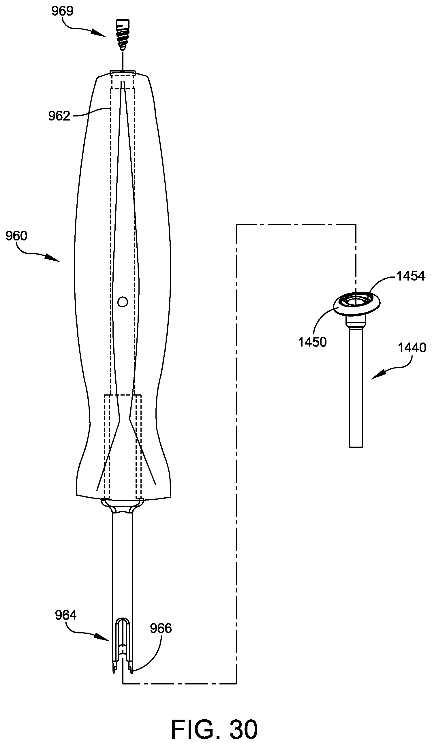
FIG. 30 illustrates a counter-torque instrument 960 having a hollow shaft 962 and an anchor engaging end 964. The counter-torque instrument 960 may be used to knotlessly lock a suture via an interference fit between a set screw such as set screw 969 and a number of appropriate anchors such as, for example, anchors 300, 370, 394, and 1440, discussed above. Focusing on anchor 1440 for purposes of example, the anchor engaging end 964 of the counter-torque instrument 960 includes spaced apart prongs 966. The prongs 966 are engageable with corresponding grooves 1454 formed in the head 1450 of the shank 1444 of the anchor 1440. This engagement provides a counter-torque force that holds the shank 1444 stationary and prevents the shank 1444 from rotating when the set screw 969 is driven or torqued down into the anchor 1440 using an appropriate set screw driver inserted through the hollow shaft 962. Thus, the surgeon may drive the set screw 969 into the anchor 1440 without fear of inadvertently torqueing or impacting the desired angular relationship between the shank 1444 and the washer 1442 of the polyaxial anchor 1440, which permits the washer 1442 to lie flush against the bone, as discussed above. This ability to counter any torsional forces generated by the driver and the set screw 969 upon the washer 1442 and/or the shank 1444 of the anchor 1440 is satisfying for the surgeon and results in more effective anchor placement and locking.
Intra Joint Constructs and Operative Sequences
FIGS. 31-54 illustrate a number of methods of according to examples of the invention in use to internally stabilize or reinforce ligaments across bone joints and/or to stabilize bone portions across bone fractures.
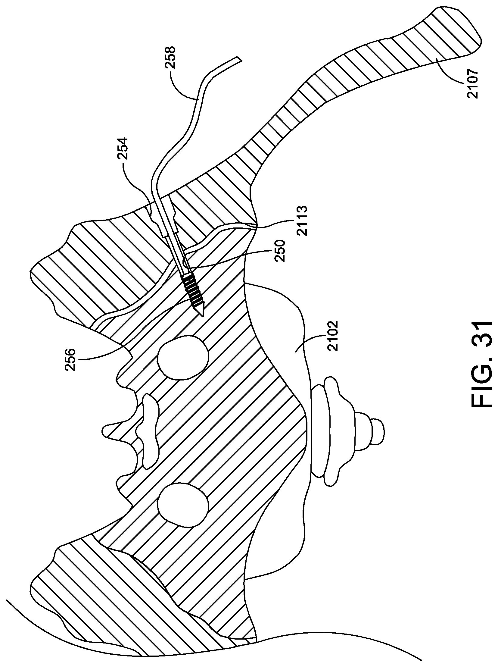
FIGS. 31-33 illustrate a repair construct in which exemplary devices are used to reinforce a fractured bone joint via a "blind hole" bone tunnel, into which a first anchor is fit, and a second anchor trails the first anchor within the blind-hole tunnel. More specifically and in one embodiment, exemplary devices are in use to repair a sacroiliac joint 2113 to stabilize the pelvis after an anterior-posterior compression fracture. FIG. 34 provides a flowchart depicting an exemplary method 1500 of reinforcing the sacroiliac joint 2113 according to the steps illustrated in FIGS. 31-33.
Referring to FIG. 31, a bone tunnel 250 is formed through the ilium 2107, across the unstable sacroiliac joint 2113, and into the sacrum 2102 (FIG. 34, 1502). A counterbore 254 is formed at the entrance of the tunnel 250 on the surface of the ilium 2107 (FIG. 34, 1504). A first anchor 256 is inserted through the tunnel 250 into the sacrum 2102 where it secures a flexible strand such as a suture 258 (FIG. 34, 1506). The flexible strand 258 extends from the trailing end of the first anchor 256 through the tunnel 250 and out the ilium 2107.
Referring to FIG. 32, the flexible strand 258 is placed through a second anchor 260 which is seated on the ilium 2107 (FIG. 34, 1506-1508). The second anchor 260 includes a tubular portion 262 that extends into the tunnel countersink 254 and a washer portion 264 that rests on the iliac surface. In the example of FIGS. 31-33, the tubular portion 262 and the washer portion 264 are separate pieces that engage on a cylindrical seat 266 to permit them to articulate relative to one another to adaptively align with the bone surface and tunnel 250. The anchors and the flexible synthetic strand or suture may include the examples disclosed above in FIGS. 13-29 and in FIGS. 5-13 of US patent application Ser. No. 15/641,592, entitled "EXTRA JOINT STABILIZATION CONSTRUCT" and co-filed with this application on Jul. 5, 2017.
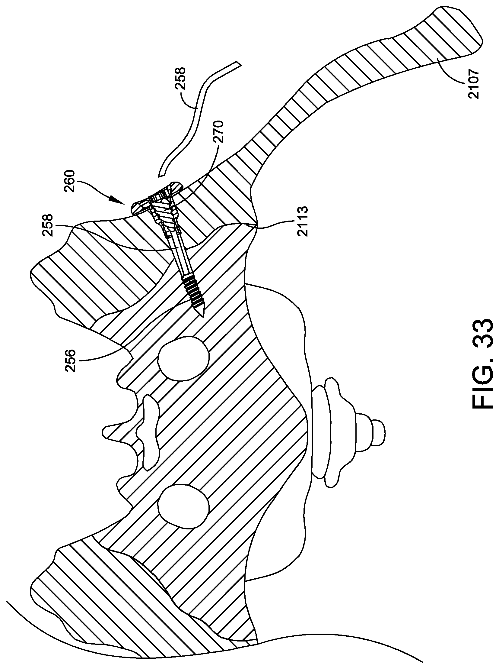
To tension the portion of the suture 258 extending between the anchors 256, 260 (FIG. 34, 1510), the end of the suture 258 may be pulled using an appropriate tension instrument of the type disclosed, for example, in FIGS. 12-15 of US patent application Ser. No. 15/642,053, entitled "COMPRESSION AND TENSION INSTRUMENTS AND METHODS OF USE TO REINFORCE LIGAMENTS" and co-filed with this application on Jul. 5, 2017. As a result, and as shown in FIG. 33, the unstable sacroiliac joint 2113 is reduced. The suture 258 may then be locked relative to the second anchor to maintain the reduction (FIG. 34, 1512). To lock, a locking set screw 270 may be advanced through a central cannulation in the tension instrument and threaded into internal threads 272 formed in the second anchor 260, thereby locking the suture 258 relative to the second anchor 260 via an interference fit between the set screw 270 and the internal threads 272 of the anchor 260. The tensioner may then be removed, and any excess length of the suture 258 may be trimmed away such that the suture 258 is flush with the anchor 260 (FIG. 34, 1514).
The sacroiliac joint 2113 repair discussed in FIGS. 31-34 may be used in place of or in conjunction with prior art iliosacral screws. The flexible construct shown in FIG. 33 is advantageous in that it provides controlled reduction of the unstable joint after placing the anchors. The joint may be tested while the tensioner is still attached, and the tension adjusted to the desired stability. The tension in the joint may be adjusted to any desired value prior to locking the suture 258 to the second anchor 260. The locking mechanism is knotless and reversible allowing for subsequent readjustment and relocking if needed and/or desired. The construct places a continuous and uninterrupted flexible member (e.g., the suture/flexible synthetic strand 258) across the joint 2113, which makes it less susceptible to failure than a rigid implant that may experience fatigue failure.
The construct of FIG. 33 may be applied at any desired location relative to the joint. The construct location may be more anterior or posterior or more superior or inferior. The first anchor 256 may be set more deeply into the sacrum. The first anchor 256 may be secured into the cortical bone on the opposite side of the sacrum from the unstable sacroiliac joint such that the suture 258 spans the sacrum. Multiple constructs may be applied to achieve a desired level of stability. Multiple constructs may be spaced apart superior-to-inferior and/or anterior-to-posterior. Further, while FIGS. 31-34 refer to the reinforcement of a sacroiliac joint 2113 to stabilize the pelvis after an anterior-posterior compression fracture, similar methods and devices may be employed as appropriate to stabilize a variety of bone joints within the body.
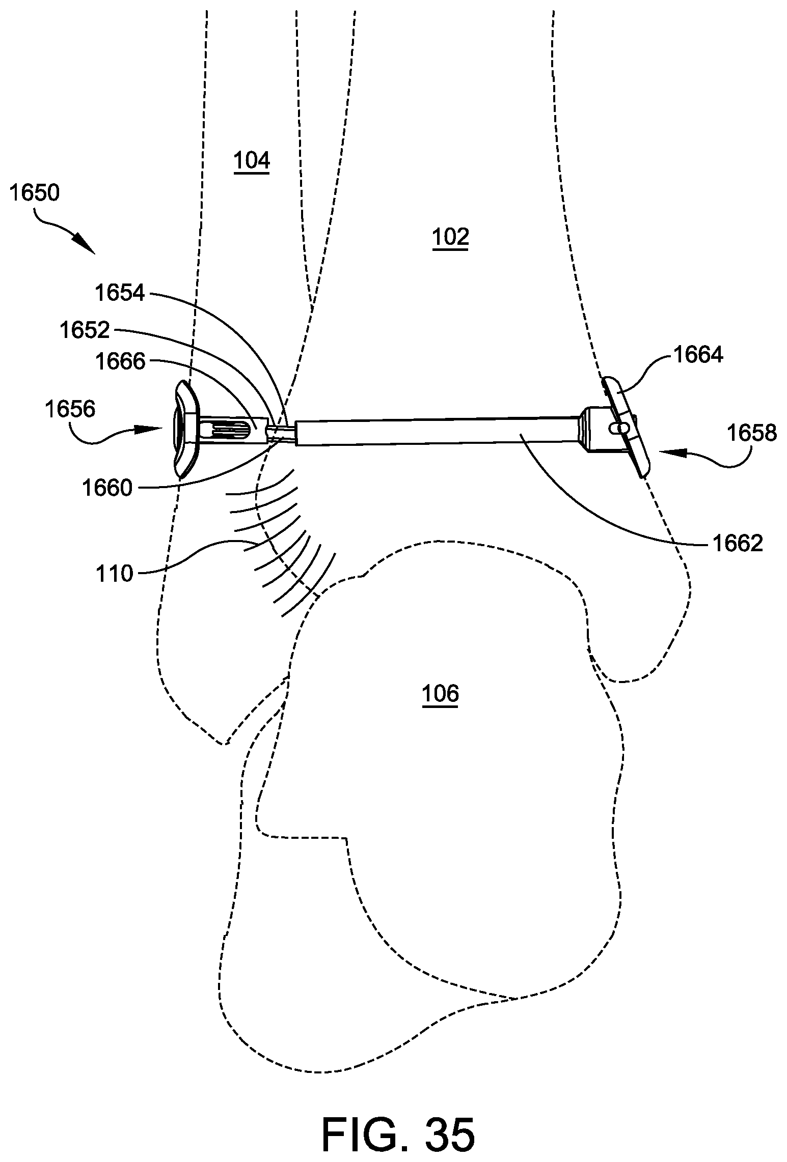
FIG. 35 illustrates exemplary devices in use to reinforce a ligament that extends across a joint between two bones. More specifically and in one embodiment, FIG. 35 illustrates a syndesmosis reduction construct 1650 for an anterior inferior tibiofibular ligament (AITFL) 110, while FIG. 36 provides a flowchart depicting an exemplary method 1600 of reinforcing the AITFL 110, as illustrated in FIG. 35.
Referring to FIG. 35, first a bone tunnel 1652 is formed through the fibula 104, and a second, coaxial and adjacent tunnel 1654 is formed within the tibia 102 (FIG. 36, 1602). A first suture returning anchor 1656 is inserted through the first tunnel 1652 into the fibula 104 (FIG. 36, 1604). The suture returning anchor may be, for example, the polyaxial suture returning anchor 920, discussed above in relation to FIGS. 6-12. A second suture locking anchor 1658 is inserted through the second tunnel 1654 into the tibia 102 (FIG. 36, 1606). The suture locking anchor may include, for example, the suture locking embodiments disclosed above in relation to FIGS. 13-29.
A flexible strand such as a suture 1660 may be threaded from the right through the second suture locking anchor 1658, returned via the first suture returning anchor 1656, and back through the first suture locking anchor 1658 (FIG. 36, 1608), such that both ends of the suture 1660 extend from the second suture locking anchor 1658, which is seated on the tibia 102.
The second anchor 1658 includes a tubular portion 1662 that extends into the tunnel 1654 and a washer portion 1664 that rests on the tibial surface. In the example of FIG. 35, the tubular portion 1662 and the washer portion 1664 are separate pieces that engage on a cylindrical seat to permit them to articulate relative to one another to adaptively align with the tunnel 1654 and the surface of the tibia 102, respectively.
To tension the suture 1660 extending between the first and second anchors 1656, 1658 (FIG. 36, 1610), the ends of the suture 1660 may be pulled using an appropriate tension instrument of the type disclosed, for example, in FIGS. 12-15 of US patent application Ser. No. 15/642,053, entitled "COMPRESSION AND TENSION INSTRUMENTS AND METHODS OF USE TO REINFORCE LIGAMENTS" and co-filed with this application on Jul. 5, 2017. As a result, and as shown in FIG. 35, the syndesmosis joint is reduced such that the ligament 110 is reinforced. The suture 1660 may then be locked relative to the second suture locking anchor 1658 to maintain the reduction (FIG. 36, 1612). The tensioner may then be removed, and any excess length of the suture 1660 may be trimmed away such that the suture 1660 is flush with the anchor 1658 (FIG. 36, 1614).
Like the sacroiliac joint repair of FIGS. 31-34, the ligament reinforcement construct 1650 discussed in relation to FIGS. 35-36 provides a continuous, uninterrupted strand from one anchor to the other along the direction of the native ligament, as well as a controlled reduction of the unstable joint after placing the anchors. The joint may be tested while the tensioner is still attached, and the tension adjusted to the desired stability. The tension may be adjusted prior to locking and readjusted as needed and/or desired. The construct places a continuous, uninterrupted flexible member (e.g., the suture 1660) across the joint, which makes it less susceptible to failure than a rigid implant that may experience fatigue failure.
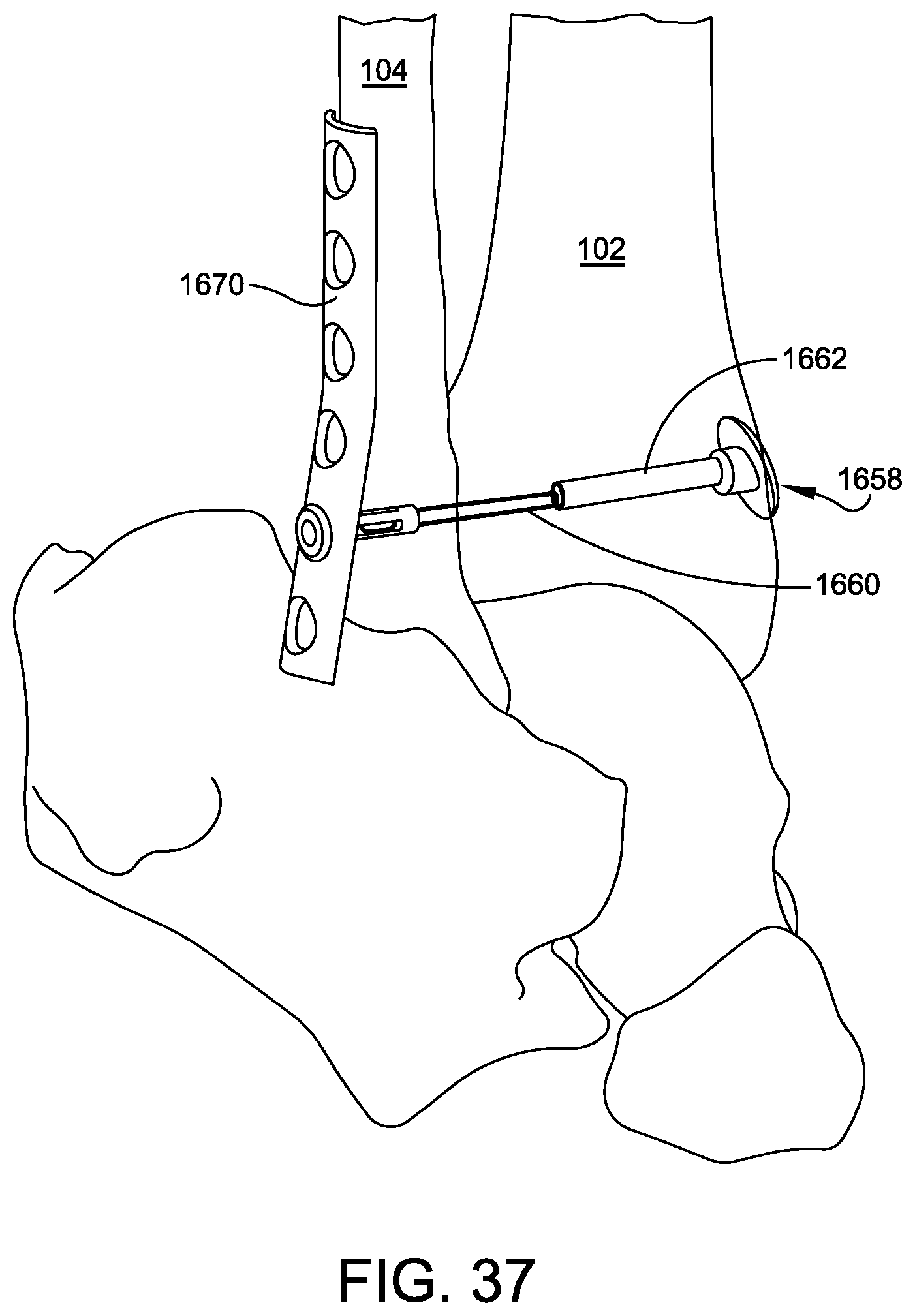
The construct 1650 of FIG. 35 may be applied at any desired location relative to the joint/ligament. The construct location may be more anterior or posterior (e.g., could be constructed to reinforce the PITFL 112) or more superior or inferior. Multiple constructs may be applied to achieve a desired level of stability. Multiple constructs may be spaced apart superior-to-inferior and/or anterior-to-posterior. Further, while FIGS. 35-36 refer to the reinforcement of the AITFL 110, similar methods and devices may be employed as appropriate to reinforce any ligament within the body. As shown in FIG. 37, the exemplary construct may be used in conjunction with a bone plate 1670.
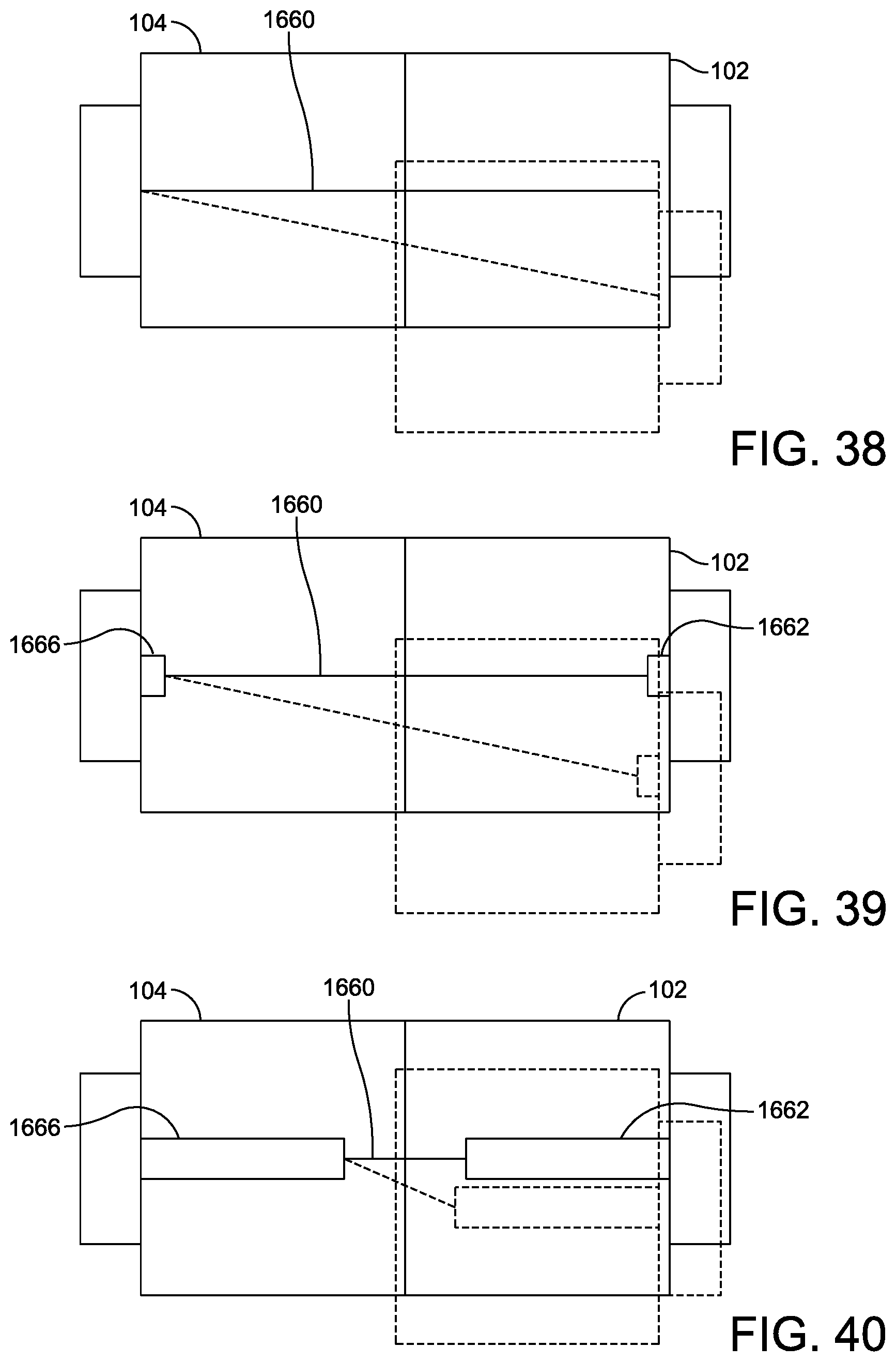
Focusing on FIG. 35, the tubular portion 1662 of the anchor 1658 serves as a suture sleeve that extends toward an end of the second bone tunnel 1654 and an inner surface of the tibia 102. Likewise, a tubular portion 1666 of the first anchor 1656 serves as a suture sleeve that extends toward an end of the bone tunnel 1652 and an inner surface of the fibula 104. The tubular portions/sheaths 1662, 1666 provide bone tunnel protection and limit transverse movement, or suture wipering, of the suture 1660 to within the space between the sleeves 1662, 1666. If the sleeves 1662 and 1666 extend to the end of the bone tunnel 1654/surface of the tibia 102 and the end of the bone tunnel 1652/surface of the fibula 104, respectively, then the suture 1660 is flexible only over a span of the natural ligament, and transverse movement or suture wipering is limited to the length of the span of the natural ligament across the joint between the bones (e.g., 1-2 mm). Because suture wipering over time abrades the bone within the bone tunnel and about the bone tunnel edges, utilizing anchors featuring hollow shafts/sheaths to contain the suture in turn reduces the abrasion of the bone caused by the suture. The further the tubular portions/sleeves 1662, 1666 extend toward the other bone, the less such suture wipering and resulting abrasion can occur.
To demonstrate, FIGS. 38-40 graphically depict that for a given amount of construct compliance--which includes suture stretch, slip, compression of the bones and the bone interface, and other factors, all represented here by a constant amount of bone overlap shown in dashed line--increasing the lengths of the tubular anchor sleeves 1662, 1666 decreases the amount of suture cutting or wipering that can occur. In other words, as the free span of the suture 1660 between the tubes/sleeves 1662, 1666 decreases from that shown in FIG. 38 to that shown in FIG. 40, there is less possible deviation in the relative positions of the bones 102, 104 and less cutting into the bones 102, 104 by the suture 1660.
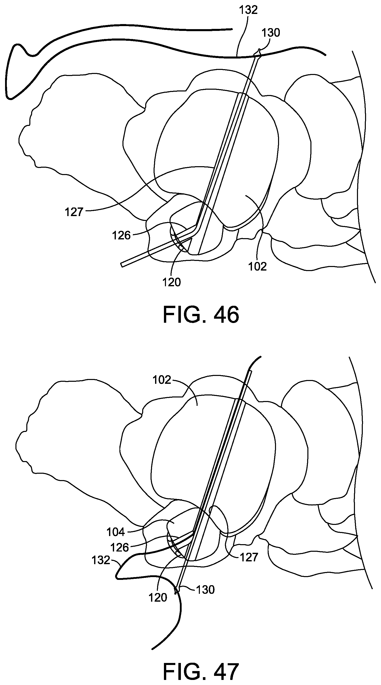
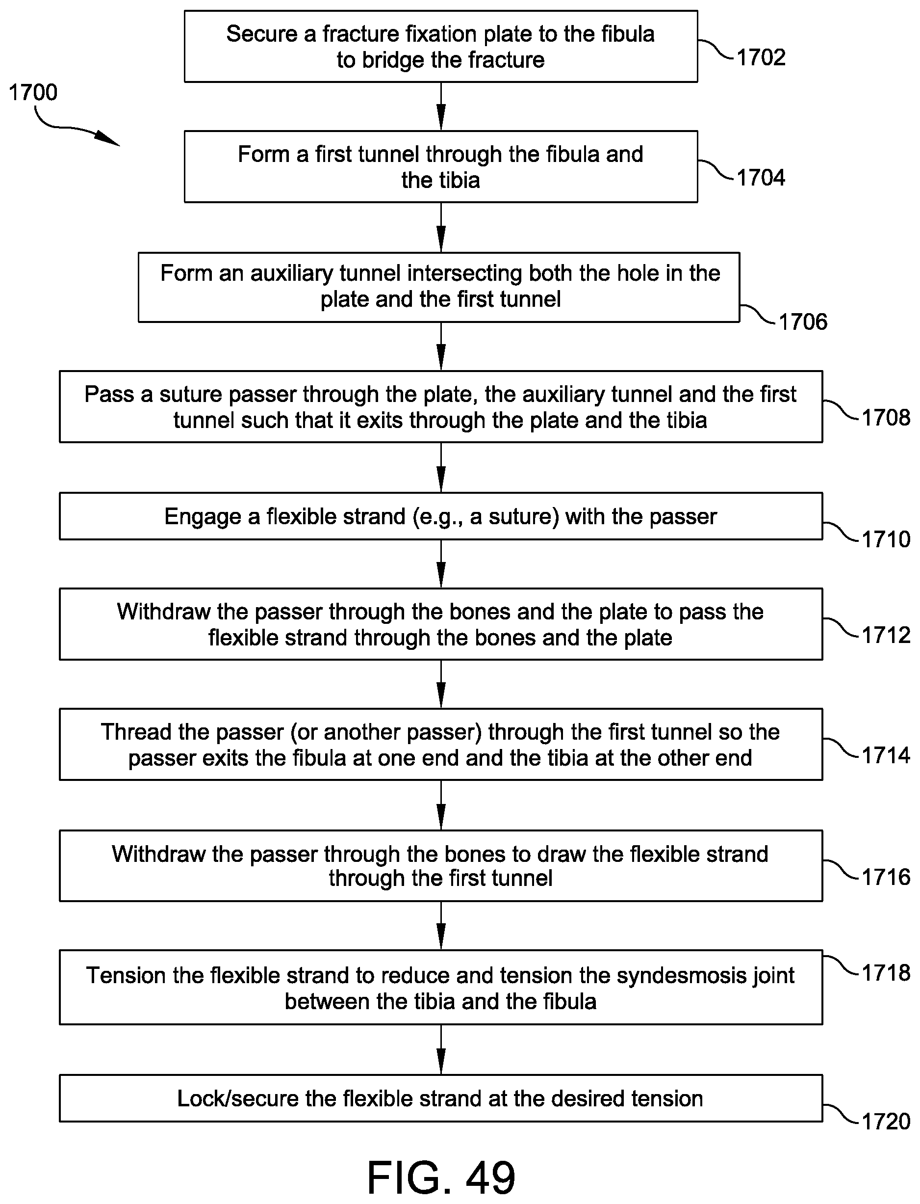
FIGS. 41-47 illustrate the steps of a method 1700 involved in a combined repair of a fibular fracture and a reinforcement of a syndesmosis joint according to exemplary devices and instruments of the invention, while FIG. 49 provides a flowchart depicting the method 1700 detailed in FIGS. 41-52. As background, FIG. 41 illustrates a lateral view of the human ankle 100 illustrating a fracture 116 of the fibular shaft 104.
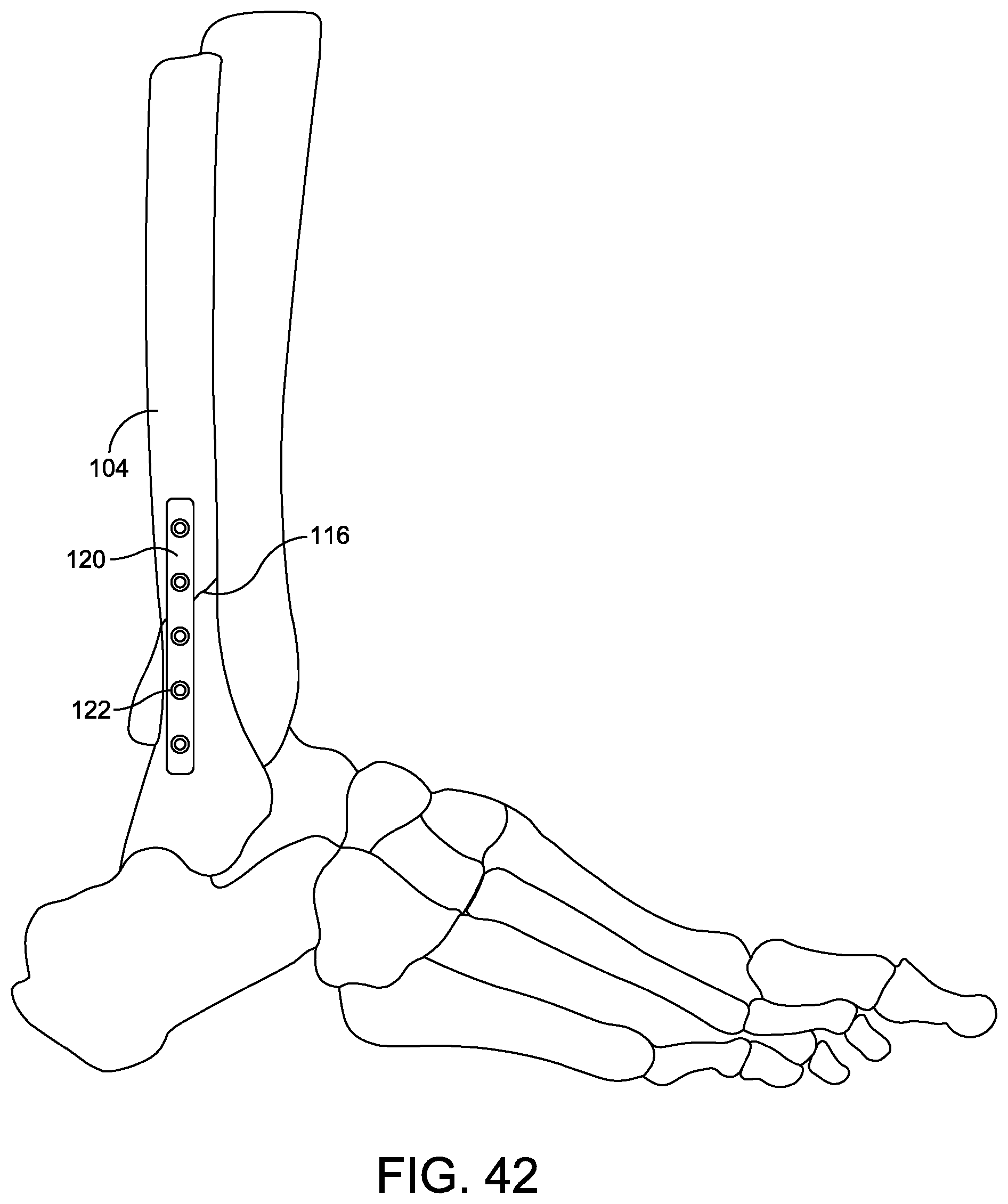
Referring to FIG. 42, a fracture fixation plate 120, as is known in the art, has been secured to the fibula 104 to bridge the fracture 116 and provide support to the fracture 116 while it heals (FIG. 49, 1702). Such a plate is typically secured by bone screws (not shown) inserted through holes 122 in the plate 120 and extending into the cortical bone on the opposite side of the bone from the plate 120. Embodiments discussed below enable a loop of flexible strand, rather than rigid hardware, to anchor the bone plate 120.
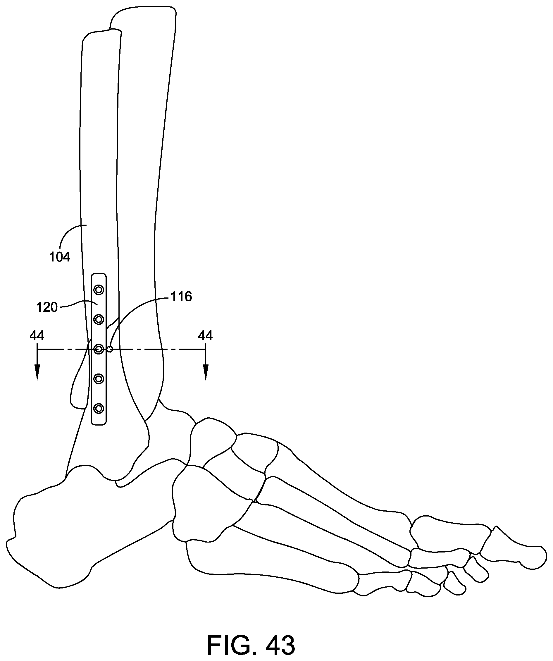
Turning to FIGS. 43-44, a first tunnel 127 has been formed through the fibula 104 and the tibia 102 to accept a stabilization element across the syndesmosis joint to stabilize the joint (FIG. 49, 1704), particularly the interosseous ligament 114. The first tunnel 127 is preferably formed adjacent the edge of the plate 120 and in the same direction as the native ligament to reinforce the ligament during healing. Preferably, the first tunnel 127 passes through the fibular ridge 125 and through the centroid of the fibula 104 and the tibia 102 at the level of fixation. In this embodiment, the first tunnel 127 is formed adjacent to an anterior edge of the plate 120. The first tunnel 127 may be spaced from the plate, more or less, and/or placed on the posterior side of the plate depending on surgeon preference and plate position. In the example of FIGS. 41-52, the plate 120 is positioned posteriorly to accommodate the preferred path for the first tunnel 120 through the bones.
The first tunnel 120 may be formed by drilling, punching, or other suitable tunnel forming means. The first tunnel 120 may be made free hand or with the aid of a guide such as a clamping and drill guide instrument like, for example, the clamp 600 disclosed in FIGS. 6-11 of US patent application Ser. No. 15/642,053, entitled "COMPRESSION AND TENSION INSTRUMENTS AND METHODS OF USE TO REINFORCE LIGAMENTS" 81243.0005) and co-filed with this application on Jul. 5, 2017.
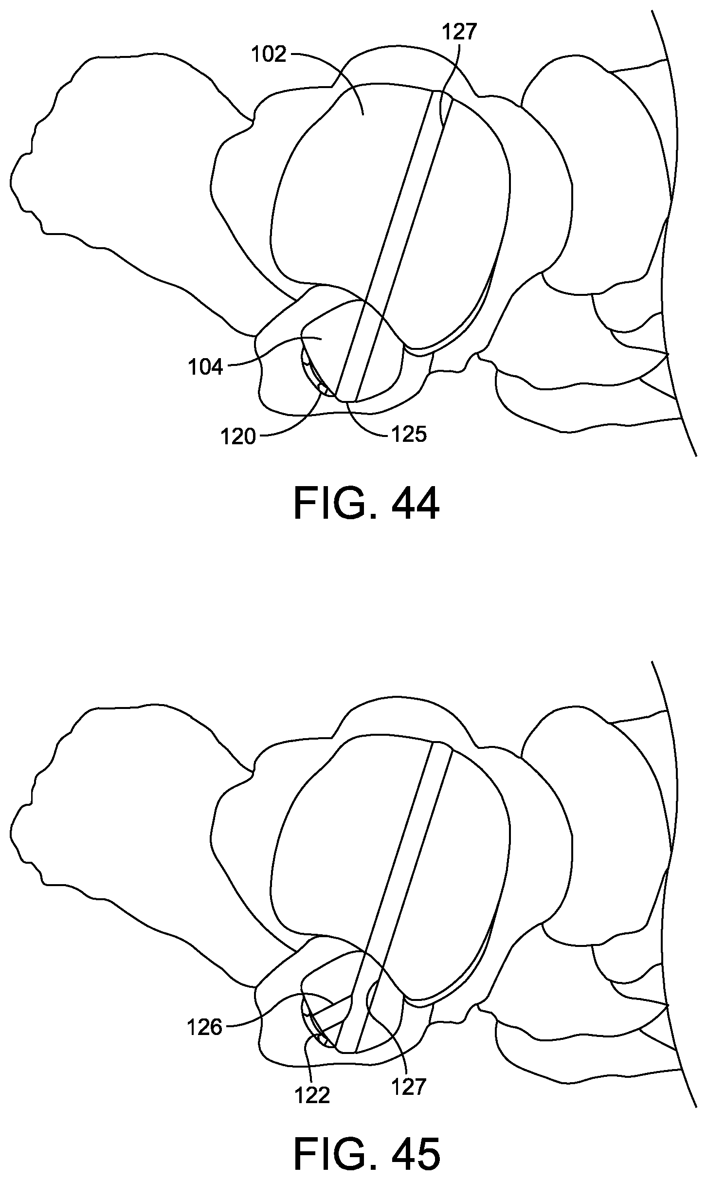
Referring to FIG. 45, an auxiliary tunnel 126 has been formed (FIG. 49, 1706). The auxiliary tunnel 126 intersects both the hole 122 in the plate 120 and the first tunnel 127. The drill may be inserted through a hole within the plate 120 such that the plate itself may serve as a drill guide for the auxiliary tunnel 126.
Next, as shown in FIG. 46, a suture passer 130 is passed through the plate 120, the auxiliary tunnel 126, and the first tunnel 127 such that it exits through the plate 120 and the tibia 102 (FIG. 49, 1708). A flexible synthetic strand 132 is then engaged with the passer 130 (FIG. 49, 1710). As discussed above, the flexible synthetic strand may be a high strength suture, suture tape, cable, or another suitable flexible synthetic strand.
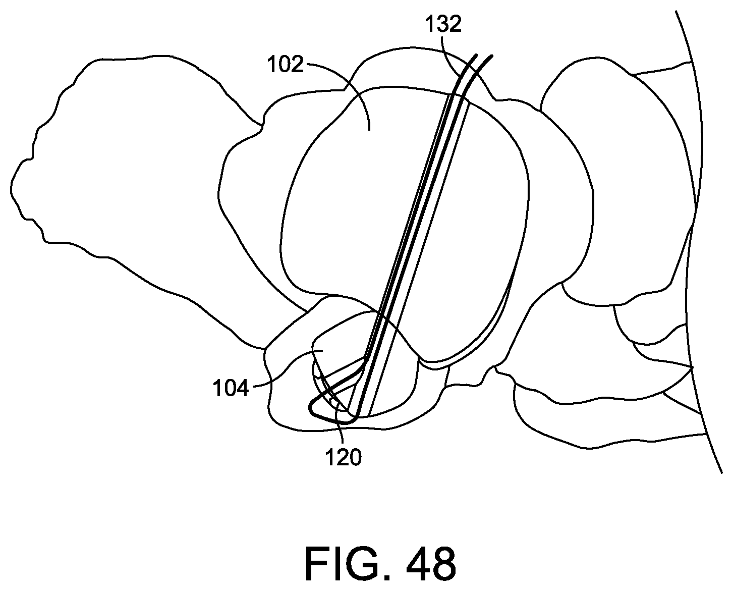
Referring to FIG. 47, the passer 130 has been withdrawn through the bones 102, 104 and the plate 120 to pass the flexible strand 132 through the bones and plate 120 (FIG. 49, 1712). The passer 130, or another passer with the flexible strand engaged 132 thereto, is then passed through the first tunnel 120 so it exits the fibula 102 at one end and the tibia 102 at the other end (FIG. 49, 1714).
FIG. 48 illustrates that the passer 130 has been withdrawn through the bones 102, 104 to pass the flexible strand 132 through the first tunnel 127 (FIG. 49, 1716). The flexible strand 132 is now looped around the anterior edge of the plate 120 with two legs of the flexible strand 132 extending across the syndesmosis joint between the tibia 102 and fibula 104. The ends of the flexible strand 132 may now be tensioned to reduce and properly tension the syndesmosis joint (FIG. 49, 1718). The tension may be applied manually by directly pulling on the ends of the flexible strand. Alternatively, a tensioning instrument, such as for example, the tension instrument 700 disclosed in FIGS. 12-15 of US patent application Ser. No. 15/642,053, entitled "COMPRESSION AND TENSION INSTRUMENTS AND METHODS OF USE TO REINFORCE LIGAMENTS" and co-filed with this application on Jul. 5, 2017, may be used to apply and/or indicate the tension. The flexible strand 132 may be secured by, for example, tying the ends over a button anchor, inserting an interference screw into the first tunnel, using one or more staples to secure the ends to the tibial bone surface adjacent the exit hole of the first tunnel 127, or securing the flexible strand with other knotless anchors such as those discussed above in relation to FIGS. 13-29 or disclosed in FIGS. 5-13 of US patent application Ser. No. 15/641,592, entitled "EXTRA JOINT STABILIZATION CONSTRUCT" and co-filed with this application on Jul. 5, 2017, and/or with other suitable means (FIG. 49, 1720).
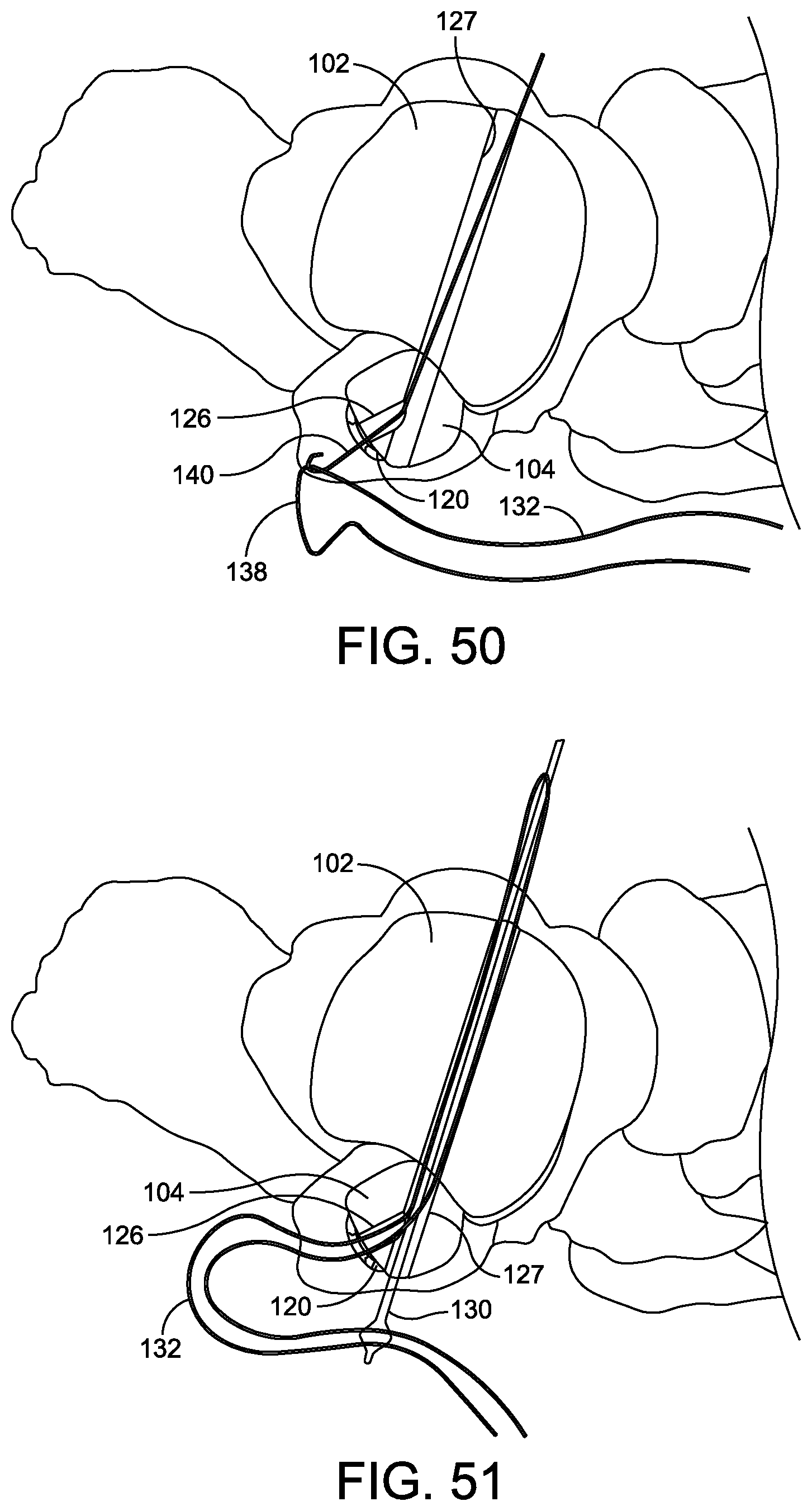
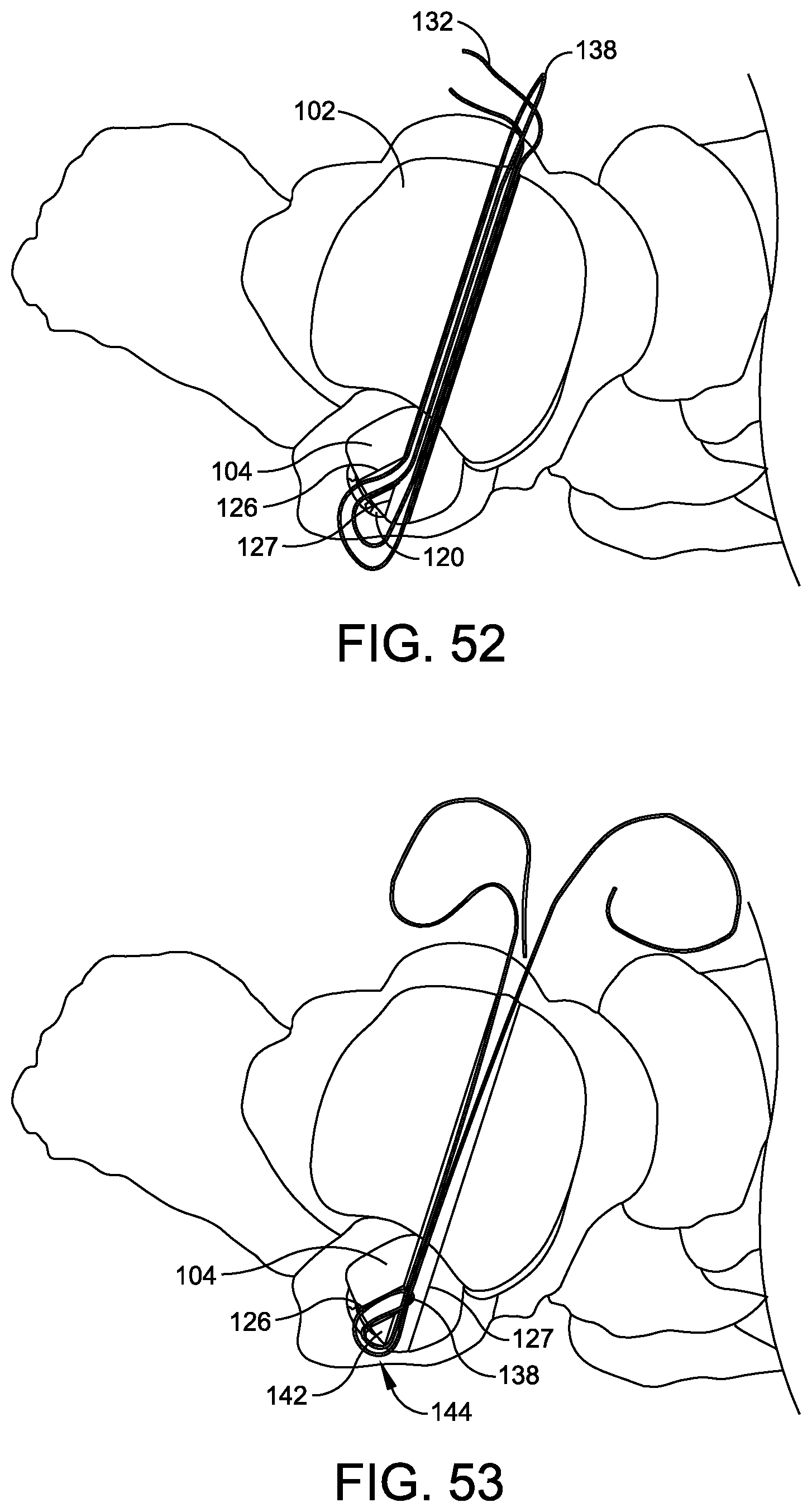
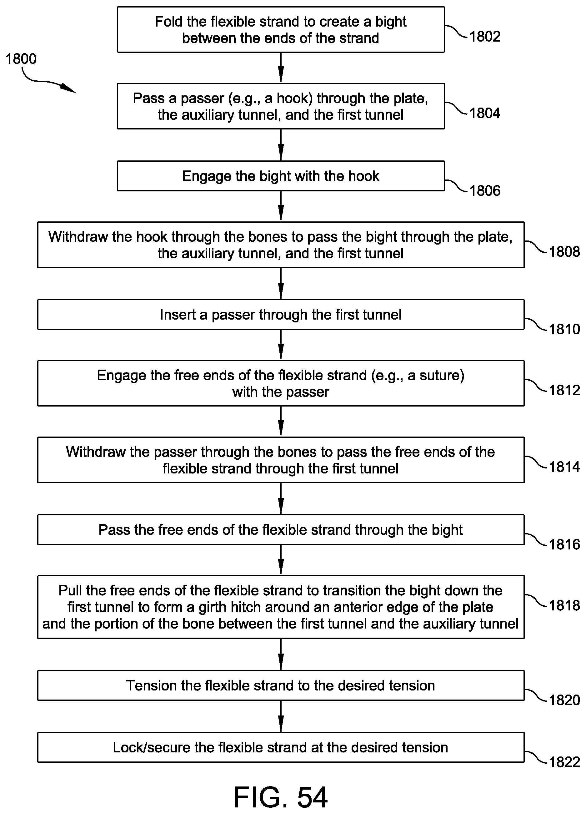
FIGS. 50-53 illustrate alternative steps for passing the flexible strand 130, while FIG. 54 provides a flowchart summarizing a corresponding method 1800. Referring to FIG. 50, the flexible strand 132 is folded to create a bight 138 between the ends of the strand (FIG. 54, 1802), preferably at the approximate center of the strand. A passer such as a hook 140 is passed through the plate 120, the auxiliary tunnel 126, and the first tunnel 127 (FIG. 54, 1804). While the passer 140 may be passed in either direction, it may be simpler to pass it retrograde through the plate 120 first to achieve the position shown in FIG. 50. Once the passer is in position, the bight 138 is engaged with the hook 140 (FIG. 54, 1806).
Referring to FIG. 51, the hook 140 has been withdrawn through the bones 102, 104 to pass the bight 138 through the plate 120, the auxiliary tunnel 126, and the first tunnel 127 to exit the tibia 102 (FIG. 54, 1808). A passer, such as passer 130, has been inserted through the first tunnel (FIG. 54, 1810), and the free ends of the flexible strand 132 are engaged with the passer (FIG. 54, 1812).
FIG. 52 illustrates the passer 130 having been withdrawn through the bones to pass the free ends of the flexible strand 132 through the first tunnel 127 (FIG. 54, 1814) before the free ends of the flexible strand 130 have been passed through the bight 138 (FIG. 54, 1816).
Referring to FIG. 53, the free ends of the flexible strand 132 have been pulled to transition the bight 138 down the first tunnel 127 and form a girth hitch 144 around the anterior edge of the plate 120 and the portion of bone 142 between the first tunnel 127 and the auxiliary tunnel 126 (FIG. 54, 1818). If needed, a push rod, forceps, or other device may be used to push on the bight 138 to aid its movement down the tunnel 127 as the free ends are pulled. Forming the girth hitch 144 as shown may improve the direction of the flexible strand 132 through the bones and reduce the tendency of the flexible strand to put pressure on the tunnel edges. The flexible strand 132 may be tensioned (FIG. 54, 1820) and secured (FIG. 54, 1822) as described above in relation to FIG. 48.
The syndesmosis reinforcement sequence according to examples of the invention achieves a very low profile with the flexible strand wrapping the plate edge to secure the bone plate, providing a flexible reinforcement with no rigid hardware spanning the joint. These benefits are accomplished while avoiding radiographic shadowing of the joint interface. Reinforcements according to examples of the invention can accommodate a variety of plate positions, such as more anterior or more posterior since the tunnel can align with, or be offset from, either the anterior or posterior edge of the plate. Reinforcements according to examples of the invention are easily revisable since the flexible strand can simply be cut and the fixation removed from the tibial side of the construct. Notably, the bone plate may be secured upon the fibula, as shown, or the tibia, as desired and/or appropriate.
Although the above embodiments have been described in language that is specific to certain structures, elements, compositions, and methodological steps, it is to be understood that the technology defined in the appended claims is not necessarily limited to the specific structures, elements, compositions and/or steps described. Rather, the specific aspects and steps are described as forms of implementing the claimed technology. Since many embodiments of the technology can be practiced without departing from the spirit and scope of the invention, the invention resides in the claims hereinafter appended.
* * * * *
References
D00000
D00001
D00002
D00003
D00004
D00005
D00006
D00007
D00008
D00009
D00010
D00011
D00012
D00013
D00014
D00015

D00016
D00017
D00018
D00019

D00020
D00021
D00022
D00023
D00024
D00025
D00026
D00027
D00028
D00029
D00030
D00031
XML
uspto.report is an independent third-party trademark research tool that is not affiliated, endorsed, or sponsored by the United States Patent and Trademark Office (USPTO) or any other governmental organization. The information provided by uspto.report is based on publicly available data at the time of writing and is intended for informational purposes only.
While we strive to provide accurate and up-to-date information, we do not guarantee the accuracy, completeness, reliability, or suitability of the information displayed on this site. The use of this site is at your own risk. Any reliance you place on such information is therefore strictly at your own risk.
All official trademark data, including owner information, should be verified by visiting the official USPTO website at www.uspto.gov. This site is not intended to replace professional legal advice and should not be used as a substitute for consulting with a legal professional who is knowledgeable about trademark law.