Surgical access system and related methods
Pimenta , et al.
U.S. patent number 10,653,308 [Application Number 15/071,540] was granted by the patent office on 2020-05-19 for surgical access system and related methods. This patent grant is currently assigned to NuVasive, Inc.. The grantee listed for this patent is NuVasive, Inc.. Invention is credited to Eric Finley, Scot Martinelli, Patrick Miles, Luiz Pimenta.


View All Diagrams
| United States Patent | 10,653,308 |
| Pimenta , et al. | May 19, 2020 |
Surgical access system and related methods
Abstract
A surgical access system including a tissue distraction assembly and a tissue retraction assembly, both of which may be equipped with one or more electrodes for use in detecting the existence of (and optionally the distance and/or direction to) neural structures before, during, and after the establishment of an operative corridor to a surgical target site. Some embodiments of the surgical access system may be particularly suited for establishing an operative corridor to a surgical target site in the spine. Such an operative corridor may be established through the retroperitoneal space and the psoas muscle during a direct lateral, retroperitoneal approach to the spine.
| Inventors: | Pimenta; Luiz (Sao Paula, BR), Miles; Patrick (San Diego, CA), Martinelli; Scot (Mountain Top, PA), Finley; Eric (Poway, CA) | ||||||||||
|---|---|---|---|---|---|---|---|---|---|---|---|
| Applicant: |
|
||||||||||
| Assignee: | NuVasive, Inc. (San Diego,
CA) |
||||||||||
| Family ID: | 34713643 | ||||||||||
| Appl. No.: | 15/071,540 | ||||||||||
| Filed: | March 16, 2016 |
Prior Publication Data
| Document Identifier | Publication Date | |
|---|---|---|
| US 20160192921 A1 | Jul 7, 2016 | |
Related U.S. Patent Documents
| Application Number | Filing Date | Patent Number | Issue Date | ||
|---|---|---|---|---|---|
| 14066098 | Oct 29, 2013 | 9314152 | |||
| 12983627 | Jan 3, 2011 | 8591432 | |||
| 12635869 | Dec 11, 2009 | 8303515 | |||
| 10967668 | Oct 18, 2004 | 7905840 | |||
| 60512594 | Oct 17, 2003 | ||||
| Current U.S. Class: | 1/1 |
| Current CPC Class: | A61B 5/04001 (20130101); A61B 5/4836 (20130101); A61B 1/32 (20130101); A61B 17/02 (20130101); A61B 2017/0256 (20130101) |
| Current International Class: | A61B 17/02 (20060101); A61B 5/00 (20060101); A61B 1/32 (20060101); A61B 5/04 (20060101) |
References Cited [Referenced By]
U.S. Patent Documents
| 208227 | September 1878 | Dorr |
| 509226 | November 1893 | Kellogg |
| 972983 | October 1910 | Arthur |
| 1003232 | October 1910 | Cerbo |
| 1044348 | June 1912 | Cerbo |
| 1328624 | January 1920 | Graham |
| 1548184 | August 1925 | Cameron |
| 1919120 | July 1933 | O'Connor et al. |
| 2594086 | April 1952 | Smith |
| 2704061 | March 1955 | Amspacker |
| 2704064 | June 1955 | Fizzell et al. |
| 2736002 | February 1956 | Oriel |
| 2808826 | October 1957 | Reiner et al. |
| 2840082 | June 1958 | Salvatore |
| 3364929 | January 1968 | Ide et al. |
| 3664329 | May 1972 | Naylor |
| 3682162 | August 1972 | Colyer |
| 3740839 | June 1973 | Otte et al. |
| 3785368 | January 1974 | McCarthy et al. |
| 3803716 | April 1974 | Garnier |
| 3830226 | August 1974 | Staub et al. |
| 3957036 | May 1976 | Normann |
| D245789 | September 1977 | Shea et al. |
| 4099519 | July 1978 | Warren |
| 4164214 | August 1979 | Stark et al. |
| 4207897 | June 1980 | Lloyd et al. |
| 4224949 | September 1980 | Scott et al. |
| 4226228 | October 1980 | Shin et al. |
| 4226288 | October 1980 | Collins, Jr. |
| 4235242 | November 1980 | Howson et al. |
| 4285347 | August 1981 | Hess |
| 4291705 | September 1981 | Severinghaus et al. |
| 4449532 | May 1984 | Storz |
| 4461300 | July 1984 | Christensen |
| 4512351 | April 1985 | Pohndorf |
| 4515168 | May 1985 | Chester et al. |
| 4519403 | May 1985 | Dickhudt |
| 4545373 | October 1985 | Christoudias |
| 4545374 | October 1985 | Jacobson |
| 4561445 | December 1985 | Berke et al. |
| 4562832 | January 1986 | Wilder et al. |
| 4573448 | March 1986 | Kambin |
| 4592369 | June 1986 | Davis et al. |
| 4595013 | June 1986 | Jones et al. |
| 4595018 | June 1986 | Rantala |
| 4611597 | September 1986 | Kraus |
| 4616635 | October 1986 | Caspar et al. |
| 4633889 | January 1987 | Talalla |
| 4658835 | April 1987 | Pohndorf |
| D295445 | April 1988 | Freeman |
| 4744371 | May 1988 | Harris |
| 4753223 | June 1988 | Bremer |
| 4759377 | July 1988 | Dykstra |
| 4784150 | November 1988 | Voorhies et al. |
| 4807642 | February 1989 | Brown |
| D300561 | April 1989 | Asa et al. |
| 4817587 | April 1989 | Janese |
| 4892105 | January 1990 | Prass |
| 4913134 | April 1990 | Luque |
| 4917274 | April 1990 | Asa et al. |
| 4917704 | April 1990 | Frey et al. |
| 4926865 | May 1990 | Oman |
| 4945896 | August 1990 | Gade |
| 4950257 | August 1990 | Hibbs et al. |
| 4962766 | October 1990 | Herzon |
| 4964411 | October 1990 | Johnson et al. |
| 5007902 | April 1991 | Witt |
| 5015247 | May 1991 | Michelson |
| 5045054 | September 1991 | Hood et al. |
| 5052373 | October 1991 | Michelson |
| 5058602 | October 1991 | Brody |
| 5081990 | January 1992 | Deletis |
| 5092344 | March 1992 | Lee |
| 5127403 | July 1992 | Brownlee |
| 5161533 | November 1992 | Prass et al. |
| 5171279 | December 1992 | Mathews |
| 5178133 | January 1993 | Pena |
| 5190561 | March 1993 | Graber |
| 5192327 | March 1993 | Brantigan |
| 5195541 | March 1993 | Obenchain |
| 5196015 | March 1993 | Neubardt |
| 5215100 | June 1993 | Spitz et al. |
| 5231974 | August 1993 | Giglio et al. |
| RE34390 | September 1993 | Culver |
| D340521 | October 1993 | Heinzelman et al. |
| 5255691 | October 1993 | Otten |
| 5261918 | November 1993 | Phillips et al. |
| 5282468 | February 1994 | Klepinski |
| 5284153 | February 1994 | Raymond et al. |
| 5284154 | February 1994 | Raymond et al. |
| 5295994 | March 1994 | Bonutti |
| 5299563 | April 1994 | Seton |
| 5312417 | May 1994 | Wilk |
| 5313956 | May 1994 | Knutsson et al. |
| 5313962 | May 1994 | Obenchain |
| 5327902 | July 1994 | Lemmen |
| 5331975 | July 1994 | Bonutti |
| 5333618 | August 1994 | Lekhtman et al. |
| 5342384 | August 1994 | Sugarbaker |
| 5357983 | October 1994 | Mathews |
| 5375067 | December 1994 | Berchin |
| 5375594 | December 1994 | Cueva |
| 5383876 | January 1995 | Nardella |
| 5395317 | March 1995 | Kambin |
| 5425772 | June 1995 | Brantigan |
| 5433739 | July 1995 | Sluijter et al. |
| 5450845 | September 1995 | Alexgaard |
| 5458638 | October 1995 | Kuslich et al. |
| 5472426 | December 1995 | Bonati et al. |
| 5474057 | December 1995 | Makower et al. |
| 5474558 | December 1995 | Neubardt |
| 5480440 | January 1996 | Kambin |
| 5482038 | January 1996 | Ruff |
| 5484437 | January 1996 | Michelson |
| 5487739 | January 1996 | Aebischer et al. |
| 5509893 | April 1996 | Pracas |
| 5514153 | May 1996 | Bonutti |
| 5540235 | July 1996 | Wilson |
| 5545222 | August 1996 | Bonutti |
| 5549656 | August 1996 | Reiss |
| 5560372 | October 1996 | Cory |
| 5562736 | October 1996 | Ray et al. |
| 5566678 | October 1996 | Cadwell |
| 5569290 | October 1996 | McAfee |
| 5571149 | November 1996 | Liss et al. |
| 5579781 | December 1996 | Cooke |
| 5593429 | January 1997 | Ruff |
| 5599279 | February 1997 | Slotman et al. |
| 5630813 | May 1997 | Kieturakis |
| 5653761 | August 1997 | Pisharodi |
| 5653762 | August 1997 | Pisharodi |
| 5667508 | September 1997 | Errico et al. |
| 5669909 | September 1997 | Zdeblick et al. |
| 5671752 | September 1997 | Sinderby et al. |
| 5681265 | October 1997 | Maeda et al. |
| 5688223 | November 1997 | Rosendahl |
| 5707359 | January 1998 | Bufalini |
| 5711307 | January 1998 | Smits |
| 5716415 | February 1998 | Steffee |
| 5720751 | February 1998 | Jackson |
| 5728046 | March 1998 | Mayer et al. |
| 5728159 | March 1998 | Stroever et al. |
| 5741253 | April 1998 | Michelson |
| 5741261 | April 1998 | Moskovitz et al. |
| 5759159 | June 1998 | Masreliez |
| 5762629 | June 1998 | Kambin |
| 5766252 | June 1998 | Henry et al. |
| 5772661 | June 1998 | Michelson |
| 5775331 | July 1998 | Raymond et al. |
| 5776144 | July 1998 | Leysieffer et al. |
| 5779642 | July 1998 | Nightengale |
| 5785658 | July 1998 | Benaron |
| 5792044 | August 1998 | Foley et al. |
| 5797854 | August 1998 | Hedgecock |
| 5797909 | August 1998 | Michelson |
| 5800550 | September 1998 | Sertich |
| 5813978 | September 1998 | Jako |
| 5814073 | September 1998 | Bonutti |
| 5814084 | September 1998 | Grivas et al. |
| 5830151 | November 1998 | Hadzic et al. |
| 5851191 | December 1998 | Gozani |
| 5851208 | December 1998 | Trott |
| 5853373 | December 1998 | Griffith et al. |
| 5860973 | January 1999 | Michelson |
| 5862314 | January 1999 | Jeddeloh |
| 5865845 | February 1999 | Thalgott |
| 5872314 | February 1999 | Clinton |
| 5885210 | March 1999 | Cox |
| 5885219 | March 1999 | Nightengale |
| 5888196 | March 1999 | Bonutti |
| 5888224 | March 1999 | Beckers et al. |
| 5891147 | April 1999 | Moskovitz et al. |
| 5893890 | April 1999 | Pisharodi |
| 5902231 | May 1999 | Foley et al. |
| 5910315 | June 1999 | Stevenson et al. |
| 5928139 | July 1999 | Koros et al. |
| 5928158 | July 1999 | Aristides |
| 5931777 | August 1999 | Sava |
| 5935131 | August 1999 | Bonutti et al. |
| 5938688 | August 1999 | Schiff |
| 5944658 | August 1999 | Koros et al. |
| 5954769 | September 1999 | Rosenlicht |
| 5968098 | October 1999 | Winslow |
| 5976094 | November 1999 | Gozani et al. |
| 5976146 | November 1999 | Ogawa et al. |
| 5993474 | November 1999 | Ouchi |
| 6004262 | December 1999 | Putz et al. |
| 6004312 | December 1999 | Finneran |
| 6004326 | December 1999 | Castro et al. |
| 6007487 | December 1999 | Foley et al. |
| 6008433 | December 1999 | Stone |
| 6010520 | January 2000 | Pattison |
| 6015436 | January 2000 | Schoenhoeffer |
| 6024696 | February 2000 | Hoftman et al. |
| 6024697 | February 2000 | Pisarik |
| 6027456 | February 2000 | Feler et al. |
| 6033405 | March 2000 | Winslow et al. |
| 6036638 | March 2000 | Nwawka |
| 6038469 | March 2000 | Karlsson et al. |
| 6038477 | March 2000 | Kayyali |
| 6039761 | March 2000 | Li et al. |
| 6042582 | March 2000 | Ray |
| 6045580 | April 2000 | Scarborough et al. |
| 6048342 | April 2000 | Zucherman et al. |
| 6050992 | April 2000 | Nichols |
| 6059829 | May 2000 | Schlaepfer et al. |
| 6063088 | May 2000 | Winslow |
| 6074343 | June 2000 | Nathanson et al. |
| 6080105 | June 2000 | Spears |
| 6083154 | July 2000 | Liu et al. |
| 6083225 | July 2000 | Winslow et al. |
| 6095987 | August 2000 | Schmulewitz |
| 6096080 | August 2000 | Nicholson et al. |
| 6104957 | August 2000 | Alo et al. |
| 6104960 | August 2000 | Duysens et al. |
| 6113638 | September 2000 | Williams et al. |
| 6120503 | September 2000 | Michelson |
| 6120506 | September 2000 | Kohrs et al. |
| 6126660 | October 2000 | Dietz |
| 6132386 | October 2000 | Gozani et al. |
| 6132387 | October 2000 | Gozani et al. |
| 6135965 | October 2000 | Turner et al. |
| 6139493 | October 2000 | Koros et al. |
| 6142931 | November 2000 | Kaji |
| 6146335 | November 2000 | Gozani |
| 6152871 | November 2000 | Foley et al. |
| 6159179 | December 2000 | Simonson |
| 6159211 | December 2000 | Boriani et al. |
| 6159215 | December 2000 | Urbahns et al. |
| 6159230 | December 2000 | Samuels |
| 6161047 | December 2000 | King et al. |
| 6174311 | January 2001 | Branch et al. |
| 6181961 | January 2001 | Prass |
| 6187000 | February 2001 | Davison et al. |
| 6193756 | February 2001 | Studer et al. |
| 6196969 | March 2001 | Bester et al. |
| 6200347 | March 2001 | Anderson et al. |
| 6206826 | March 2001 | Mathews et al. |
| 6206922 | March 2001 | Zdeblick et al. |
| 6217509 | April 2001 | Foley et al. |
| 6224545 | May 2001 | Cocchia et al. |
| 6224549 | May 2001 | Drongelen |
| 6224607 | May 2001 | Michelson |
| 6224631 | May 2001 | Kohrs |
| 6241771 | June 2001 | Gresser et al. |
| 6245082 | June 2001 | Gellman et al. |
| 6251140 | June 2001 | Marino et al. |
| 6258125 | July 2001 | Paul et al. |
| 6259945 | July 2001 | Epstein et al. |
| 6264651 | July 2001 | Underwood et al. |
| 6266558 | July 2001 | Gozani et al. |
| 6273905 | August 2001 | Streeter |
| 6277149 | August 2001 | Boyle et al. |
| 6292701 | September 2001 | Prass et al. |
| 6306100 | October 2001 | Prass |
| 6308712 | October 2001 | Shaw |
| 6312392 | November 2001 | Herzon |
| 6319257 | November 2001 | Carignan et al. |
| 6325764 | December 2001 | Griffith et al. |
| 6334068 | December 2001 | Hacker |
| 6348058 | February 2002 | Melkent et al. |
| 6360750 | March 2002 | Gerber et al. |
| 6371968 | April 2002 | Kogasaka et al. |
| 6371989 | April 2002 | Chauvin et al. |
| 6383221 | May 2002 | Scarborough et al. |
| 6395007 | May 2002 | Bhatnagar et al. |
| 6409766 | June 2002 | Brett |
| 6416465 | July 2002 | Brau |
| 6425859 | July 2002 | Foley et al. |
| 6425887 | July 2002 | McGuckin et al. |
| 6425901 | July 2002 | Zhu et al. |
| 6432048 | August 2002 | Francois |
| 6432140 | August 2002 | Lin |
| 6440142 | August 2002 | Ralph et al. |
| 6442814 | September 2002 | Landry et al. |
| 6450952 | September 2002 | Rioux et al. |
| 6451015 | September 2002 | Rittman, III et al. |
| 6454806 | September 2002 | Cohen et al. |
| 6466817 | October 2002 | Kaula et al. |
| 6468205 | October 2002 | Mollenauer et al. |
| 6468207 | October 2002 | Fowler, Jr. |
| 6468311 | October 2002 | Boyd et al. |
| 6491724 | December 2002 | Ferree |
| 6500116 | December 2002 | Knapp |
| 6500128 | December 2002 | Marino |
| 6520907 | February 2003 | Foley et al. |
| 6524320 | February 2003 | DiPoto |
| 6535759 | March 2003 | Epstein et al. |
| D472634 | April 2003 | Anderson |
| D472650 | April 2003 | Green |
| 6564078 | May 2003 | Marino et al. |
| 6579244 | June 2003 | Goodwin |
| 6595998 | July 2003 | Johnson et al. |
| 6599294 | July 2003 | Fuss et al. |
| 6620157 | September 2003 | Dabney et al. |
| 6626905 | September 2003 | Schmiel et al. |
| 6635086 | October 2003 | Lin |
| 6645194 | November 2003 | Briscoe et al. |
| 6648895 | November 2003 | Burkus et al. |
| 6672019 | January 2004 | Wenz et al. |
| 6676703 | January 2004 | Biscup |
| 6679833 | January 2004 | Smith et al. |
| 6706067 | March 2004 | Shimp et al. |
| 6719692 | April 2004 | Kleffner et al. |
| 6746484 | June 2004 | Liu et al. |
| 6755841 | June 2004 | Fraser et al. |
| 6760616 | July 2004 | Hoey et al. |
| 6761739 | July 2004 | Shepard |
| 6770074 | August 2004 | Michelson |
| 6796985 | September 2004 | Bolger et al. |
| 6810281 | October 2004 | Brock et al. |
| 6819956 | November 2004 | DiLorenzo |
| 6824564 | November 2004 | Crozet |
| 6829508 | December 2004 | Schulman et al. |
| 6830570 | December 2004 | Frey et al. |
| 6847849 | January 2005 | Mamo et al. |
| 6849047 | February 2005 | Goodwin |
| 6855105 | February 2005 | Jackson, III et al. |
| 6869398 | March 2005 | Obenchain |
| 6871099 | March 2005 | Whitehurst et al. |
| D503801 | April 2005 | Jackson |
| 6902569 | June 2005 | Parmer et al. |
| 6916330 | July 2005 | Simonson |
| 6926728 | August 2005 | Zucherman et al. |
| 6929606 | August 2005 | Ritland |
| 6942698 | September 2005 | Jackson |
| 6945933 | September 2005 | Branch |
| 6951538 | October 2005 | Ritland |
| 6964687 | November 2005 | Bernard et al. |
| 6979353 | December 2005 | Bresina |
| 6984245 | January 2006 | McGahan et al. |
| 6986788 | January 2006 | Paul et al. |
| 6989031 | January 2006 | Michelson |
| 7018416 | March 2006 | Hanson et al. |
| 7047082 | May 2006 | Schrom et al. |
| 7050848 | May 2006 | Hoey et al. |
| 7079883 | July 2006 | Marino et al. |
| 7089059 | August 2006 | Pless |
| D530423 | October 2006 | Miles et al. |
| 7166113 | January 2007 | Arambula et al. |
| 7177677 | February 2007 | Kaula et al. |
| 7198598 | April 2007 | Smith et al. |
| 7207949 | April 2007 | Miles et al. |
| 7226451 | June 2007 | Shluzas et al. |
| 7261688 | August 2007 | Smith et al. |
| 7470236 | December 2008 | Kelleher et al. |
| 7473222 | January 2009 | Dewey et al. |
| 7481766 | January 2009 | Lee et al. |
| 7522953 | April 2009 | Kaula et al. |
| 7556601 | July 2009 | Branch et al. |
| 7582058 | September 2009 | Miles et al. |
| 7643884 | January 2010 | Pond et al. |
| 7691057 | April 2010 | Miles et al. |
| 7693562 | April 2010 | Marino et al. |
| 7717959 | May 2010 | William et al. |
| 7819801 | October 2010 | Miles et al. |
| 7892173 | February 2011 | Miles et al. |
| 7905840 | March 2011 | Pimenta et al. |
| 7918891 | April 2011 | Curran et al. |
| 7920922 | April 2011 | Kaula et al. |
| 7935051 | May 2011 | Miles et al. |
| 7962191 | June 2011 | Marino et al. |
| 7963927 | June 2011 | Kelleher et al. |
| 7991463 | August 2011 | Kelleher et al. |
| 8000782 | August 2011 | Gharib et al. |
| 8005535 | August 2011 | Gharib et al. |
| 8016767 | September 2011 | Miles et al. |
| 8021430 | September 2011 | Michelson |
| 8055349 | November 2011 | Kaula et al. |
| 8068912 | November 2011 | Gharib et al. |
| 8114019 | February 2012 | Miles et al. |
| 8133173 | March 2012 | Miles et al. |
| 8137284 | March 2012 | Miles et al. |
| 8172750 | May 2012 | Miles et al. |
| 8182423 | May 2012 | Miles et al. |
| 8187179 | May 2012 | Miles et al. |
| 8187334 | May 2012 | Curran et al. |
| 8192356 | June 2012 | Miles et al. |
| 8192357 | June 2012 | Miles et al. |
| 8244343 | August 2012 | Gharib et al. |
| 8246686 | August 2012 | Curran et al. |
| 8251997 | August 2012 | Michelson |
| 8303458 | November 2012 | Fukano et al. |
| 8303498 | November 2012 | Miles et al. |
| 8303515 | November 2012 | Pimenta et al. |
| 8337410 | December 2012 | Kelleher et al. |
| 8343046 | January 2013 | Miles et al. |
| 8343224 | January 2013 | Lynn et al. |
| 8355780 | January 2013 | Miles et al. |
| 8361156 | January 2013 | Curran et al. |
| 8388527 | March 2013 | Miles |
| 8403841 | March 2013 | Miles et al. |
| 8439832 | May 2013 | Miles et al. |
| 8489170 | July 2013 | Marino et al. |
| 8500634 | August 2013 | Miles et al. |
| 8512235 | August 2013 | Miles et al. |
| 8523768 | September 2013 | Miles et al. |
| 8548579 | October 2013 | Gharib et al. |
| 8550994 | October 2013 | Miles et al. |
| 8556808 | October 2013 | Miles et al. |
| 8562521 | October 2013 | Miles et al. |
| 8574301 | November 2013 | Curran et al. |
| 8591432 | November 2013 | Pimenta et al. |
| 8602982 | December 2013 | Miles et al. |
| 8608804 | December 2013 | Curran et al. |
| 8628469 | January 2014 | Miles et al. |
| 8634904 | January 2014 | Kaula et al. |
| 8663100 | March 2014 | Miles et al. |
| 8672840 | March 2014 | Miles et al. |
| 8673005 | March 2014 | Pimenta et al. |
| 8679006 | March 2014 | Miles et al. |
| 8685105 | April 2014 | Curran et al. |
| 8696559 | April 2014 | Miles et al. |
| 8708899 | April 2014 | Miles et al. |
| 8738123 | May 2014 | Gharib et al. |
| 8740783 | June 2014 | Gharib et al. |
| 8747307 | June 2014 | Miles et al. |
| 8753270 | June 2014 | Miles et al. |
| 8753271 | June 2014 | Miles et al. |
| 8764649 | July 2014 | Miles et al. |
| 8768450 | July 2014 | Gharib et al. |
| 8780899 | July 2014 | Tillman et al. |
| 8812116 | August 2014 | Kaula et al. |
| 8814940 | August 2014 | Curran et al. |
| 8821396 | September 2014 | Miles et al. |
| 8915846 | December 2014 | Miles et al. |
| 8942801 | January 2015 | Miles et al. |
| 8945004 | February 2015 | Miles et al. |
| 8956283 | February 2015 | Miles et al. |
| 8958869 | February 2015 | Kelleher et al. |
| 8977352 | March 2015 | Gharib et al. |
| 9014776 | April 2015 | Marino et al. |
| 9037250 | May 2015 | Kaula et al. |
| 9180021 | November 2015 | Curran et al. |
| 9186261 | November 2015 | Pimenta et al. |
| 9204871 | December 2015 | Miles et al. |
| 9265493 | February 2016 | Miles et al. |
| 9301743 | April 2016 | Miles et al. |
| 9314152 | April 2016 | Pimenta et al. |
| 9387090 | July 2016 | Arnold et al. |
| 9456783 | October 2016 | Kaula et al. |
| 9468405 | October 2016 | Miles et al. |
| 9474627 | October 2016 | Curran et al. |
| 9486329 | November 2016 | Pimenta et al. |
| 9572562 | February 2017 | Miles et al. |
| 9610071 | April 2017 | Miles et al. |
| 9636233 | May 2017 | Arnold et al. |
| 2001/0037123 | November 2001 | Hancock |
| 2001/0039949 | November 2001 | Loubser |
| 2001/0056280 | December 2001 | Underwood et al. |
| 2002/0007129 | January 2002 | Marino |
| 2002/0010392 | January 2002 | Desai |
| 2002/0013514 | January 2002 | Brau |
| 2002/0016592 | February 2002 | Branch et al. |
| 2002/0065481 | May 2002 | Cory et al. |
| 2002/0072686 | June 2002 | Hoey et al. |
| 2002/0077632 | June 2002 | Tsou |
| 2002/0123744 | September 2002 | Reynard |
| 2002/0123780 | September 2002 | Grill et al. |
| 2002/0147387 | October 2002 | Paolitto et al. |
| 2002/0161415 | October 2002 | Cohen et al. |
| 2002/0193843 | December 2002 | Hill et al. |
| 2003/0032966 | February 2003 | Foley et al. |
| 2003/0070682 | April 2003 | Wilson et al. |
| 2003/0083688 | May 2003 | Simonson |
| 2003/0105503 | June 2003 | Marino |
| 2003/0105528 | June 2003 | Shimp et al. |
| 2003/0109928 | June 2003 | Pasquet et al. |
| 2003/0139648 | July 2003 | Foley et al. |
| 2003/0149341 | August 2003 | Clifton |
| 2003/0225405 | December 2003 | Weiner |
| 2003/0236544 | December 2003 | Lunsford et al. |
| 2004/0181165 | September 2004 | Hoey et al. |
| 2004/0199084 | October 2004 | Kelleher et al. |
| 2004/0225228 | November 2004 | Ferree |
| 2004/0230191 | November 2004 | Frey et al. |
| 2005/0004593 | January 2005 | Simonson |
| 2005/0004623 | January 2005 | Miles et al. |
| 2005/0033380 | February 2005 | Tanner et al. |
| 2005/0060006 | March 2005 | Pflueger et al. |
| 2005/0075578 | April 2005 | Gharib et al. |
| 2005/0080320 | April 2005 | Lee et al. |
| 2005/0149035 | July 2005 | Pimenta et al. |
| 2005/0149054 | July 2005 | Gorek |
| 2005/0182454 | August 2005 | Gharib et al. |
| 2005/0192575 | September 2005 | Pacheco |
| 2005/0203538 | September 2005 | Lo et al. |
| 2005/0228232 | October 2005 | Gillinov et al. |
| 2005/0277812 | December 2005 | Myles |
| 2006/0025703 | February 2006 | Miles et al. |
| 2006/0052826 | March 2006 | Kim et al. |
| 2006/0052828 | March 2006 | Kim et al. |
| 2006/0069315 | March 2006 | Miles et al. |
| 2006/0224078 | October 2006 | Hoey et al. |
| 2006/0235529 | October 2006 | Ralph et al. |
| 2006/0247658 | November 2006 | Pond, Jr. et al. |
| 2007/0016097 | January 2007 | Farquhar et al. |
| 2007/0021682 | January 2007 | Gharib et al. |
| 2007/0049931 | March 2007 | Justis et al. |
| 2007/0049962 | March 2007 | Marino et al. |
| 2007/0072475 | March 2007 | Justin et al. |
| 2007/0100212 | May 2007 | Pimenta et al. |
| 2007/0198062 | August 2007 | Miles et al. |
| 2007/0208228 | September 2007 | Pavento et al. |
| 2007/0260317 | November 2007 | Ankney et al. |
| 2007/0270842 | November 2007 | Bankoski et al. |
| 2007/0293782 | December 2007 | Marino |
| 2008/0058606 | March 2008 | Miles et al. |
| 2008/0058838 | March 2008 | Steinberg |
| 2008/0064976 | March 2008 | Kelleher et al. |
| 2008/0064977 | March 2008 | Kelleher et al. |
| 2008/0065135 | March 2008 | Marino et al. |
| 2008/0065144 | March 2008 | Marino et al. |
| 2008/0065178 | March 2008 | Kelleher et al. |
| 2008/0071191 | March 2008 | Kelleher et al. |
| 2008/0077138 | March 2008 | Cohen et al. |
| 2008/0097164 | April 2008 | Miles et al. |
| 2008/0103601 | May 2008 | Biro et al. |
| 2008/0146885 | June 2008 | Protopsaltis |
| 2008/0183214 | July 2008 | Copp et al. |
| 2008/0221394 | September 2008 | Melkent et al. |
| 2008/0288077 | November 2008 | Reo et al. |
| 2008/0300465 | December 2008 | Feigenwinter et al. |
| 2009/0030519 | January 2009 | Falahee |
| 2009/0124860 | May 2009 | Miles et al. |
| 2009/0132049 | May 2009 | Carver et al. |
| 2009/0138050 | May 2009 | Ferree |
| 2009/0138090 | May 2009 | Hurlbert et al. |
| 2009/0192403 | July 2009 | Gharib et al. |
| 2009/0204016 | August 2009 | Gharib et al. |
| 2010/0069783 | March 2010 | Miles et al. |
| 2010/0106251 | April 2010 | Kast |
| 2010/0130827 | May 2010 | Pimenta et al. |
| 2010/0152603 | June 2010 | Miles et al. |
| 2010/0160738 | June 2010 | Miles et al. |
| 2010/0174146 | July 2010 | Miles |
| 2010/0174148 | July 2010 | Miles et al. |
| 2010/0228350 | September 2010 | Gornet et al. |
| 2011/0046448 | February 2011 | Paolitto et al. |
| 2011/0218631 | September 2011 | Woodburn, Sr. et al. |
| 2011/0313530 | December 2011 | Gharib et al. |
| 2012/0238822 | September 2012 | Miles |
| 2012/0238893 | September 2012 | Farquhar et al. |
| 2013/0331943 | December 2013 | Arnold et al. |
| 2014/0235950 | August 2014 | Miles et al. |
| 2014/0288374 | September 2014 | Miles et al. |
| 2014/0288375 | September 2014 | Miles et al. |
| 2015/0150693 | June 2015 | Gharib et al. |
| 2015/0157227 | June 2015 | Kelleher et al. |
| 2015/0157228 | June 2015 | Marino et al. |
| 2015/0282948 | October 2015 | Arnold et al. |
| 2016/0120530 | May 2016 | Miles et al. |
| 2016/0174958 | June 2016 | Miles et al. |
| 2016/0174959 | June 2016 | Miles et al. |
| 2016/0192921 | July 2016 | Pimenta et al. |
| 2016/0374613 | December 2016 | Kaula et al. |
| 2017/0007421 | January 2017 | Curran et al. |
| 2017/0020503 | January 2017 | Miles et al. |
| 2017/0027712 | February 2017 | Pimenta et al. |
| 2017/0143514 | May 2017 | Gharib et al. |
| 2017/0143515 | May 2017 | Gharib et al. |
| 2017/0156580 | June 2017 | Miles et al. |
| 2017/0164938 | June 2017 | Miles et al. |
| 2017/0172558 | June 2017 | Miles et al. |
| 299 08 259 | Jul 1999 | DE | |||
| 100 48 790 | Apr 2002 | DE | |||
| 0 334 116 | Sep 1989 | EP | |||
| 0 567 424 | Oct 1993 | EP | |||
| 0 972 538 | Jan 2000 | EP | |||
| 1 002 500 | May 2000 | EP | |||
| 2 795 624 | Jan 2001 | FR | |||
| 793186 | May 1990 | JP | |||
| 10-14928 | Mar 1996 | JP | |||
| 3019990007098 | Nov 1999 | KR | |||
| 94/28824 | Dec 1994 | WO | |||
| 97/00702 | Jan 1997 | WO | |||
| 98/23324 | Jun 1998 | WO | |||
| 99/52446 | Oct 1999 | WO | |||
| 00/27291 | May 2000 | WO | |||
| 00/38574 | Jul 2000 | WO | |||
| 00/44288 | Aug 2000 | WO | |||
| WO-0062660 | Oct 2000 | WO | |||
| 00/66217 | Nov 2000 | WO | |||
| 00/67645 | Nov 2000 | WO | |||
| 01/08563 | Feb 2001 | WO | |||
| 01/37728 | May 2001 | WO | |||
| 01/60263 | Aug 2001 | WO | |||
| 02/054960 | Jul 2002 | WO | |||
| 02/058780 | Aug 2002 | WO | |||
| 02/71953 | Sep 2002 | WO | |||
| 02/87678 | Nov 2002 | WO | |||
| 03/005887 | Jan 2003 | WO | |||
| 03/026482 | Apr 2003 | WO | |||
| 03/037170 | May 2003 | WO | |||
| WO-03084398 | Oct 2003 | WO | |||
| WO-2004064634 | Aug 2004 | WO | |||
| 05/013805 | Feb 2005 | WO | |||
| 05/030318 | Apr 2005 | WO | |||
| 06/042241 | Apr 2006 | WO | |||
| 06/066217 | Jun 2006 | WO | |||
| WO-2007035925 | Mar 2007 | WO | |||
| WO-2007136784 | Nov 2007 | WO | |||
| WO-2009055034 | Apr 2009 | WO | |||
| WO-2011059491 | May 2011 | WO | |||
| WO-2011059498 | May 2011 | WO | |||
| WO-2012026981 | Mar 2012 | WO | |||
| WO-2012103254 | Aug 2012 | WO | |||
| WO-2013028571 | Feb 2013 | WO | |||
Other References
|
510(K) No. K002677, approved by the FDA on Nov. 13, 2000, 634 pages. cited by applicant . 510(K) No. K013215, approved by the FDA on Oct. 16, 2001, 376 pages. cited by applicant . Co-pending U.S. Appl. No. 15/498,296, filed Apr. 26, 2017. cited by applicant . Co-pending U.S. Appl. No. 90/013,464, filed Mar. 6, 2015. cited by applicant . Co-pending U.S. Appl. No. 90/013,546, filed Jul. 8, 2015. cited by applicant . Co-pending U.S. Appl. No. 90/013,605, filed Oct. 8, 2015. cited by applicant . Co-pending U.S. Appl. No. 95/001,247, filed Oct. 27, 2009. cited by applicant . Co-pending U.S. Appl. No. 95/001,888, filed Feb. 9, 2012. cited by applicant . Co-pending U.S. Appl. No. 95/001,890, filed Feb. 9, 2012. cited by applicant . European Search Report dated Apr. 7, 2015 for EP Application No. 12826211.0. cited by applicant . European Search Report dated Aug. 2, 2012 for EP Application No. 12001129.1. cited by applicant . European Search Report dated Sep. 28, 2009 for EP Application No. 02778359.6. cited by applicant . In re: NuVasive, Inc., in 2015-1670 decided on Dec. 7, 2016, 13 Pages. cited by applicant . In re: NuVasive, Inc., in 2015-1672, 2015-1673 decided on Nov. 9, 2016, 16 Pages. cited by applicant . In re: NuVasive, Inc., in 2015-1838 signed on May 10, 2017, 2 Pages. cited by applicant . In re: NuVasive, Inc., in 2015-1839, 2015-1840 signed on May 10, 2017, 2 Pages. cited by applicant . In re: NuVasive, Inc., in 2015-1841 decided on May 31, 2017, 16 Pages. cited by applicant . In re: NuVasive, Inc., in 2015-1842, 2015-1843 signed on May 10, 2017, 2 Pages. cited by applicant . In re: Warsaw Orthopedic, Inc. In 15-1050 filed Oct. 14, 2014. cited by applicant . In re: Warsaw Orthopedic, Inc. In 15-1058 filed Oct. 17, 2014. cited by applicant . International Search Report dated Jan. 12, 2011 for International Application No. PCT/US2010/002960. cited by applicant . International Search Report dated Feb. 9, 2005 for International Application PCT/US2004/031768. cited by applicant . International Search Report dated Mar. 27, 2003 for International Application PCT/US2002/022247. cited by applicant . International Search Report dated Jun. 5, 2003 for International Application No. PCT/US2002/030617. cited by applicant . International Search Report dated Jul. 24, 2012 for International Application No. PCT/US2012/022600. cited by applicant . International Search Report dated Oct. 29, 2012 for International Application No. PCT/US2012/051480. cited by applicant . International Search Report dated Dec. 13, 2011 for International Application No. PCT/US2011/001489. cited by applicant . International Search Report dated Dec. 24, 2008 for International Application No. PCT/US2008/012121. cited by applicant . International Search Report dated Mar. 23, 2011 for International Application No. PCT/US2010/002951. cited by applicant . Medtronic Sofamor Danek "UNION TM / UNION-L TM Anterior & Lateral Impacted Fusion Devices: Clear choice of stabilization," Medtronic Sofamor Danek, 2000, 4 pages. cited by applicant . Notice of allowance dated Jan. 14, 2016 for U.S. Appl. No. 14/066,098. cited by applicant . Notice of Allowance dated Mar. 30, 2017 for U.S. Appl. No. 14/263,797. cited by applicant . Notice of Allowance dated Apr. 12, 2017 for U.S. Appl. No. 15/272,071. cited by applicant . NuVasive, Inc. v. Medtronic, Inc. in 15-1674 filed May 26, 2015, Individual documents of the referenced court case are not being submitted herewith, as Applicant understands the documents to be readily accessible by the Examiner. However, Applicant can provide any of the documents upon request. cited by applicant . NuVasive, Inc. v. Medtronic, Inc. in 15-1712 filed Jun. 8, 2015, Individual documents of the referenced court case are not being submitted herewith, as Applicant understands the documents to be readily accessible by the Examiner. However, Applicant can provide any of the documents upon request. cited by applicant . NuVasive, Inc. v. Warsaw Orthopedic, Inc. in 15-1049 filed Oct. 14, 2014, Individual documents of the referenced court case are not being submitted herewith, as Applicant understands the documents to be readily accessible by the Examiner. However, Applicant can provide any of the documents upon request. cited by applicant . NuVasive Vertebral Body Access System, 2000, 1 page. cited by applicant . Office Action dated Jan. 11, 2012 for U.S. Appl. No. 11/982,185. cited by applicant . Office Action dated Jan. 12, 2012 for U.S. Appl. No. 11/489,020. cited by applicant . Office Action dated Jan. 21, 2011 for U.S. Appl. No. 11/982,185. cited by applicant . Office Action dated Feb. 26, 2016 for U.S. Appl. No. 14/622,585. cited by applicant . Office Action dated Mar. 16, 2009 for U.S. Appl. No. 11/489,020. cited by applicant . Office Action dated Mar. 29, 2017 for U.S. Appl. No. 15/448,395. cited by applicant . Office Action dated Apr. 5, 2017 for U.S. Appl. No. 15/445,854. cited by applicant . Office Action dated Apr. 6, 2017 for U.S. Appl. No. 15/439,889. cited by applicant . Office Action dated Apr. 7, 2017 for U.S. Appl. No. 15/059,215. cited by applicant . Office Action dated Apr. 29, 2010 for U.S. Appl. No. 11/982,185. cited by applicant . Office Action dated May 6, 2010 for U.S. Appl. No. 11/489,020. cited by applicant . Office Action dated May 8, 2014 for U.S. Appl. No. 13/964,836. cited by applicant . Office Action dated Jun. 17, 2009 for U.S. Appl. No. 11/982,185. cited by applicant . Office action dated Jul. 15, 2015 for U.S. Appl. No. 14/066,098. cited by applicant . Office Action dated Sep. 15, 2008 for U.S. Appl. No. 11/489,020. cited by applicant . Office Action dated Sep. 19, 2016 for U.S. Appl. No. 14/263,797. cited by applicant . Office Action dated Sep. 23, 2016 for U.S. Appl. No. 14/622,585. cited by applicant . Office Action dated Oct. 9, 2009 for U.S. Appl. No. 11/489,020. cited by applicant . Office Action dated Oct. 20, 2016 for U.S. Appl. No. 14/297,369. cited by applicant . Office Action dated Nov. 28, 2016 for U.S. Appl. No. 14/994,640. cited by applicant . Office Action dated Nov. 4, 2016 for U.S. Appl. No. 14/297,438. cited by applicant . Office Action dated Dec. 19, 2014 for U.S. Appl. No. 13/964,836. cited by applicant . Office action dated Dec. 22, 2014 for U.S. Appl. No. 14/066,098. cited by applicant . Patent Trial and Appeal Board Decision from IPR 2014-00087, dated Apr. 8, 2014, 31 pages. Individual documents of the referenced court case are not being submitted herewith, as Applicant understands the documents to be readily accessible by the Examiner. However, Applicant can provide any of the documents upon request. cited by applicant . Petition for Inter Partes Review by Medtronic, Inc. in IPR2013-00504 filed Aug. 14, 2013, Individual documents of the referenced court case are not being submitted herewith, as Applicant understands the documents to be readily accessible by the Examiner. However, Applicant can provide any of the documents upon request. cited by applicant . Petition for Inter Partes Review by Medtronic, Inc. in IPR2013-00506 filed Aug. 14, 2013, Individual documents of the referenced court case are not being submitted herewith, as Applicant understands the documents to be readily accessible by the Examiner. However, Applicant can provide any of the documents upon request. cited by applicant . Petition for Inter Partes Review by Medtronic, Inc. in IPR2013-00507 filed Aug. 14, 2013, Individual documents of the referenced court case are not being submitted herewith, as Applicant understands the documents to be readily accessible by the Examiner. However, Applicant can provide any of the documents upon request. cited by applicant . Petition for Inter Partes Review by Medtronic, Inc. in IPR2013-00508 filed Aug. 14, 2013, Individual documents of the referenced court case are not being submitted herewith, as Applicant understands the documents to be readily accessible by the Examiner. However, Applicant can provide any of the documents upon request. cited by applicant . Petition for Inter Partes Review by Medtronic, Inc. in IPR2014-00034 filed Oct. 8, 2013, Individual documents of the referenced court case are not being submitted herewith, as Applicant understands the documents to be readily accessible by the Examiner. However, Applicant can provide any of the documents upon request. cited by applicant . Petition for Inter Partes Review by Medtronic, Inc. in IPR2014-00035 filed Oct. 8, 2013, Individual documents of the referenced court case are not being submitted herewith, as Applicant understands the documents to be readily accessible by the Examiner. However, Applicant can provide any of the documents upon request. cited by applicant . Petition for Inter Partes Review by Medtronic, Inc. in IPR2014-00071 filed Oct. 16, 2013, Individual documents of the referenced court case are not being submitted herewith, as Applicant understands the documents to be readily accessible by the Examiner. However, Applicant can provide any of the documents upon request. cited by applicant . Petition for Inter Partes Review by Medtronic, Inc. in IPR2014-00073 filed Oct. 18, 2013, Individual documents of the referenced court case are not being submitted herewith, as Applicant understands the documents to be readily accessible by the Examiner. However, Applicant can provide any of the documents upon request. cited by applicant . Petition for Inter Partes Review by Medtronic, Inc. in IPR2014-00074 filed Oct. 18, 2013, Individual documents of the referenced court case are not being submitted herewith, as Applicant understands the documents to be readily accessible by the Examiner. However, Applicant can provide any of the documents upon request. cited by applicant . Petition for Inter Partes Review by Medtronic, Inc. in IPR2014-00075 filed Oct. 21, 2013, Individual documents of the referenced court case are not being submitted herewith, as Applicant understands the documents to be readily accessible by the Examiner. However, Applicant can provide any of the documents upon request. cited by applicant . Petition for Inter Partes Review by Medtronic, Inc. in IPR2014-00076 filed Oct. 21, 2013, Individual documents of the referenced court case are not being submitted herewith, as Applicant understands the documents to be readily accessible by the Examiner. However, Applicant can provide any of the documents upon request. cited by applicant . Petition for Inter Partes Review by Medtronic, Inc. in IPR2014-00081 filed Oct. 22, 2013, Individual documents of the referenced court case are not being submitted herewith, as Applicant understands the documents to be readily accessible by the Examiner. However, Applicant can provide any of the documents upon request. cited by applicant . Petition for Inter Partes Review by Medtronic, Inc. in IPR2014-00087 filed Oct. 22, 2013, Individual documents of the referenced court case are not being submitted herewith, as Applicant understands the documents to be readily accessible by the Examiner. However, Applicant can provide any of the documents upon request. cited by applicant . Petition for Inter Partes Review by Medtronic, Inc. in IPR2014-00487 filed Mar. 5, 2014, Individual documents of the referenced court case are not being submitted herewith, as Applicant understands the documents to be readily accessible by the Examiner. However, Applicant can provide any of the documents upon request. cited by applicant . Petition for Inter Partes Review by NuVasive, Inc. in IPR2013-00206 filed Mar. 22, 2013, Individual documents of the referenced court case are not being submitted herewith, as Applicant understands the documents to be readily accessible by the Examiner. However, Applicant can provide any of the documents upon request. cited by applicant . Petition for Inter Partes Review by NuVasive, Inc. in IPR2013-00208 filed Mar. 22, 2013, Individual documents of the referenced court case are not being submitted herewith, as Applicant understands the documents to be readily accessible by the Examiner. However, Applicant can provide any of the documents upon request. cited by applicant . Petition for Inter Partes Review by NuVasive, Inc. in IPR2013-00395 filed Jun. 27, 2013, Individual documents of the referenced court case are not being submitted herewith, as Applicant understands the documents to be readily accessible by the Examiner. However, Applicant can provide any of the documents upon request. cited by applicant . Petition for Inter Partes Review by NuVasive, Inc. in IPR2013-00396 filed Jun. 27, 2013, Individual documents of the referenced court case are not being submitted herewith, as Applicant understands the documents to be readily accessible by the Examiner. However, Applicant can provide any of the documents upon request. cited by applicant . Petition for Inter Partes Review by NuVasive, Inc. in IPR2015-00502 filed Dec. 24, 2014, Individual documents of the referenced court case are not being submitted herewith, as Applicant understands the documents to be readily accessible by the Examiner. However, Applicant can provide any of the documents upon request. cited by applicant . Warsaw Orthopedic, Inc. v. NuVasive, Inc. in 12-1263 filed Mar. 15, 2012. cited by applicant . Warsaw Orthopedic, Inc. v. NuVasive, Inc. in 12-1266 filed Mar. 15, 2012. cited by applicant . Warsaw Orthopedic, Inc. v. NuVasive, Inc. in 13-1576 filed Aug. 21, 2013. cited by applicant . Warsaw Orthopedic, Inc. v. NuVasive, Inc. in 13-1577 filed Aug. 21, 2013. cited by applicant . INS-1 Guide Dec. 31, 2000, Part I. cited by applicant . INS-1 Guide Dec. 31, 2000, Part II. cited by applicant . INS-1 Guide Dec. 31, 2000, Part III. cited by applicant. |
Primary Examiner: Henson; Devin B
Assistant Examiner: Nguyen; H.Q.
Parent Case Text
CROSS REFERENCE TO RELATED APPLICATIONS
This application is a continuation of U.S. patent application Ser. No. 14/066,098 (filed on Oct. 29, 2013), which is a continuation of U.S. patent application Ser. No. 12/983,627 (filed on Jan. 3, 2011), now U.S. Pat. No. 8,591,432, entitled "Surgical Access System and Related Methods," which is a continuation of U.S. patent application Ser. No. 12/635,869 (filed on Dec. 11, 2009), now U.S. Pat. No. 8,303,515, entitled "Surgical Access System and Related Methods," which is a continuation of U.S. patent application Ser. No. 10/967,668 (filed on Oct. 18, 2004), now U.S. Pat. No. 7,905,840, entitled "Surgical Access System and Related Methods," which claims the benefit of priority from U.S. Provisional Patent Application Ser. No. 60/512,594 (filed on Oct. 17, 2003) entitled "System and Methods for Performing Lateral Lumbar Surgery," the entire contents of all these prior applications are hereby expressly incorporated by reference into this disclosure as if set forth fully herein. The present application also incorporates by reference the following co-assigned patent applications in their entireties: PCT App. Ser. No. PCT/US02/22247, entitled "System and Methods for Determining Nerve Proximity, Direction, and Pathology During Surgery," filed on Jul. 11, 2002; PCT App. Ser. No. PCT/US02/30617, entitled "System and Methods for Performing Surgical Procedures and Assessments," filed on Sep. 25, 2002; PCT App. Ser. No. PCT/US02/35047, entitled "System and Methods for Performing Percutaneous Pedicle Integrity Assessments," filed on Oct. 30, 2002; and PCT App. Ser. No. PCT/US03/02056, entitled "System and Methods for Determining Nerve Direction to a Surgical Instrument," filed Jan. 15, 2003 (collectively "NeuroVision PCT Applications").
Claims
What is claimed is:
1. A method of inserting a spinal implant along a lateral path to a targeted lumbar disc space, the method comprising: while a user's finger is inserted through a skin incision, moving a tip portion of the user's finger through bodily tissue in a retroperitoneal space that is lateral from a psoas muscle and a targeted lumbar disc space and contacting the tip portion of the user's finger with the psoas muscle; after contacting the tip portion of the user's finger with the psoas muscle, advancing a dilator system along a lateral path to the targeted lumbar disc space, the dilator system comprising: a first cannulated dilator that is advanced to the targeted lumbar disc space, one or more sequential dilators that are advanced along the lateral path, wherein the first cannulated dilator comprises a central lumen configured to receive an elongate inner member, and wherein one or more of said first cannulated dilator, said one or more sequential dilators, and said elongate inner member includes a stimulation electrode that outputs electrical stimulation for nerve monitoring when the stimulation electrode is positioned in the lateral path; slidably advancing a multi-blade retractor assembly over an outermost dilator of the dilator system toward the targeted lumbar disc space along the lateral path, the multi-blade retractor assembly including a blade adjuster apparatus and a plurality of retractor blades extending from the blade adjuster apparatus, wherein the plurality of retractor blades are slidably advanced over the outermost dilator while in a first position in which the plurality of retractor blades are configured to simultaneously slide over the outermost dilator of the dilator system, wherein the blade adjuster apparatus is operable to adjust the plurality of retractor blades to a second position in which a first retractor blade is moved away from a second retractor blade; removing at least a portion of the dilator system after the multi-blade retractor assembly is advanced along the lateral path, wherein a lateral operative corridor to the targeted lumbar disc space is at least partially defined by the plurality of retractor blades; inserting a spinal implant that is releasably secured to an inserter tool through the lateral operative corridor maintained by the multi-blade retractor assembly and into the targeted lumbar disc space; and releasing the spinal implant from the inserter tool when the spinal implant is positioned in the targeted lumbar disc space.
2. The method of claim 1, further comprising moving arm portions of the blade adjuster apparatus so that the plurality of retractor blades are adjusted to the second position before the step of inserting the spinal implant.
3. The method of claim 2, further comprising releasably engaging a fixation element with one of the plurality of retractor blades so that at least a portion of the fixation element extends distally from the one of the plurality of retractor blades and anchors into a portion of the spine.
4. The method of claim 3, wherein the fixation element comprises a posterior shim element that releasably engages with a posterior-most retractor blade of the plurality of retractor blades.
5. The method of claim 3, further comprising releasably engaging retractor blade extenders with corresponding retractor blades of the plurality of retractor blades, the retractor blade extenders being different from the fixation element.
6. The method of claim 1, wherein the step of moving the tip portion of the user's finger through the bodily tissue separates fatty tissue in the retroperitoneal space before the dilator system is advanced into the retroperitoneal space.
7. The method of claim 1, further comprising activating one or more light emitting devices to direct light through the lateral operative corridor toward the targeted lumbar disc space, each of the one or more light emitting device being releasably coupled to a respective one of the plurality of retractor blades.
8. The method of claim 1, further comprising inserting at least one preparation tool through the lateral operative corridor formed by the multi-blade retractor assembly along the lateral path so as to remove a portion of a spinal disc from the targeted lumbar disc space.
9. The method of claim 8, further comprising inserting a sizer instrument into the targeted lumbar disc space before the spinal implant is inserted into the targeted lumbar disc space.
10. The method of claim 1, wherein the blade adjuster apparatus comprises: two pivotable arm portions and a knob element that is rotatable relative to a linear rack member having teeth.
11. The method of claim 1, wherein the elongate inner member is deliverable along the lateral path to the targeted lumbar disc space such that a distal tip portion of the elongate inner member penetrates into an annulus of a spinal disc at the targeted lumbar disc space.
12. The method of claim 1, wherein the elongate inner member comprises a K-wire.
13. The method of claim 1, wherein the first cannulated dilator is advanced to the targeted lumbar disc space together with the elongate inner member received within the central lumen of the first cannulated dilator.
14. The method of claim 1, wherein when the multi-blade retractor assembly is in the first position, each retractor blade of the plurality of retractor blades at least partially abuts a neighboring retractor blade of the plurality of retractor blades.
15. The method of claim 1, wherein the skin incision through which the user's finger is inserted is different from a skin penetration point of the first cannulated dilator.
16. The method of claim 1, wherein the step of advancing the dilator system along the lateral path to the targeted lumbar disc space comprises advancing the dilator system along a trans-psoas path through the psoas muscle.
17. The method of claim 1, wherein the step of slidably advancing the multi-blade retractor assembly along the lateral path comprises advancing the multi-blade retractor assembly along a trans-psoas path through the psoas muscle.
18. The method of claim 1, further comprising: activating a nerve monitoring system that delivers an electrical stimulation signal to the stimulation electrode of the first cannulated dilator during delivery of the first cannulated dilator along the lateral path to the targeted lumbar disc space, the nerve monitoring system detecting neuromuscular responses via a set of sensors in leg muscle myotomes associated with nerves in the vicinity of the targeted lumbar disc space; and during advancement of the first cannulated dilator along the lateral path to the targeted lumbar disc space, viewing a video display device of the nerve monitoring system that displays a numeric stimulation threshold that changes in response to the detection of said neuromuscular responses via said set of sensor in said leg muscle myotomes.
19. The method of claim 1, further comprising: activating a nerve monitoring system that delivers an electrical stimulation signal to the stimulation electrode of the elongate inner member during delivery of the elongate inner member along the lateral path to the targeted lumbar disc space, the nerve monitoring system detecting neuromuscular responses via a set of sensors in leg muscle myotomes associated with nerves in the vicinity of the targeted lumbar disc space; and during advancement of the elongate inner member along the lateral path to the targeted lumbar disc space, viewing a video display device of the nerve monitoring system that displays a numeric stimulation threshold that changes in response to the detection of said neuromuscular responses via said set of sensor in said leg muscle myotomes.
20. The method of claim 1, further comprising guiding the elongate inner member through the retroperitoneal space along the lateral path while covering a distal region of the elongate inner member with the tip portion of the user's finger.
Description
BACKGROUND OF THE INVENTION
I. Field of the Invention
The present invention relates generally to systems and methods for performing surgical procedures and, more particularly, for accessing a surgical target site in order to perform surgical procedures.
II. Discussion of the Prior Art
A noteworthy trend in the medical community is the move away from performing surgery via traditional "open" techniques in favor of minimally invasive or minimal access techniques. Open surgical techniques are generally undesirable in that they typically require large incisions and high amounts of tissue displacement to gain access to the surgical target site, which produces concomitantly high amounts of pain, lengthened hospitalization (increasing health care costs), and high morbidity in the patient population. Less-invasive surgical techniques (including so-called "minimal access" and "minimally invasive" techniques) are gaining favor due to the fact that they involve accessing the surgical target site via incisions of substantially smaller size with greatly reduced tissue displacement requirements. This, in turn, reduces the pain, morbidity and cost associated with such procedures. The access systems developed to date, however, fail in various respects to meet all the needs of the surgeon population.
One drawback associated with prior art surgical access systems relates to the ease with which the operative corridor can be created, as well as maintained over time, depending upon the particular surgical target site. For example, when accessing surgical target sites located beneath or behind musculature or other relatively strong tissue (such as, by way of example only, the psoas muscle adjacent to the spine), it has been found that advancing an operative corridor-establishing instrument directly through such tissues can be challenging and/or lead to unwanted or undesirable effects (such as stressing or tearing the tissues). While certain efforts have been undertaken to reduce the trauma to tissue while creating an operative corridor, such as (by way of example only) the sequential dilation system of U.S. Pat. No. 5,792,044 to Foley et al., these attempts are nonetheless limited in their applicability based on the relatively narrow operative corridor. More specifically, based on the generally cylindrical nature of the so-called "working cannula," the degree to which instruments can be manipulated and/or angled within the cannula can be generally limited or restrictive, particularly if the surgical target site is a relatively deep within the patient.
Efforts have been undertaken to overcome this drawback, such as shown in U.S. Pat. No. 6,524,320 to DiPoto, wherein an expandable portion is provided at the distal end of a cannula for creating a region of increased cross-sectional area adjacent to the surgical target site. While this system may provide for improved instrument manipulation relative to sequential dilation access systems (at least at deep sites within the patient), it is nonetheless flawed in that the deployment of the expandable portion may inadvertently compress or impinge upon sensitive tissues adjacent to the surgical target site. For example, in anatomical regions having neural and/or vasculature structures, such a blind expansion may cause the expandable portion to impinge upon these sensitive tissues and cause neural and/or vasculature compromise, damage and/or pain for the patient.
This highlights yet another drawback with the prior art surgical access systems, namely, the challenges in establishing an operative corridor through or near tissue having major neural structures which, if contacted or impinged, may result in neural impairment for the patient. Due to the threat of contacting such neural structures, efforts thus far have largely restricted to establishing operative corridors through tissue having little or substantially reduced neural structures, which effectively limits the number of ways a given surgical target site can be accessed. This can be seen, by way of example only, in the spinal arts, where the exiting nerve roots and neural plexus structures in the psoas muscle have rendered a lateral or far lateral access path (so-called trans-psoas approach) to the lumbar spine virtually impossible. Instead, spine surgeons are largely restricted to accessing the spine from the posterior (to perform, among other procedures, posterior lumbar interbody fusion (PLIF)) or from the anterior (to perform, among other procedures, anterior lumbar interbody fusion (ALIF)).
Posterior-access procedures involve traversing a shorter distance within the patient to establish the operative corridor, albeit at the price of oftentimes having to reduce or cut away part of the posterior bony structures (i.e. lamina, facets, spinous process) in order to reach the target site (which typically comprises the disc space). Anterior-access procedures are relatively simple for surgeons in that they do not involve reducing or cutting away bony structures to reach the surgical target site. However, they are nonetheless disadvantageous in that they require traversing through a much greater distance within the patient to establish the operative corridor, oftentimes requiring an additional surgeon to assist with moving the various internal organs out of the way to create the operative corridor.
The present invention is directed at eliminating, or at least minimizing the effects of, the above-identified drawbacks in the prior art.
SUMMARY OF THE INVENTION
The present invention accomplishes this goal by providing a novel access system and related methods which involve detecting the existence of (and optionally the distance and/or direction to) neural structures before, during, and after the establishment of an operative corridor through (or near) any of a variety of tissues having such neural structures which, if contacted or impinged, may otherwise result in neural impairment for the patient. It is expressly noted that, although described herein largely in terms of use in spinal surgery, the access system of the present invention is suitable for use in any number of additional surgical procedures wherein tissue having significant neural structures must be passed through (or near) in order to establish an operative corridor.
According to one broad aspect of the present invention, the access system comprises a tissue distraction assembly and a tissue retraction assembly, both of which may be equipped with one or more electrodes for use in detecting the existence of (and optionally the distance and/or direction to) neural structures. The tissue distraction assembly (in conjunction with one or more elements of the tissue retraction assembly) is capable of, as an initial step, distracting a region of tissue between the skin of the patient and the surgical target site. The tissue retraction assembly is capable of, as a secondary step, being introduced into this distracted region to thereby define and establish the operative corridor. Once established, any of a variety of surgical instruments, devices, or implants may be passed through and/or manipulated within the operative corridor depending upon the given surgical procedure. The electrode(s) are capable of, during both tissue distraction and retraction, detecting the existence of (and optionally the distance and/or direction to) neural structures such that the operative corridor may be established through (or near) any of a variety of tissues having such neural structures which, if contacted or impinged, may otherwise result in neural impairment for the patient. In this fashion, the access system of the present invention may be used to traverse tissue that would ordinarily be deemed unsafe or undesirable, thereby broadening the number of manners in which a given surgical target site may be accessed.
The tissue distraction assembly may include any number of components capable of performing the necessary distraction. By way of example only, the tissue distraction assembly may include a K-wire, an initial dilator of split construction, and one or more dilators of traditional (that is, non-split) construction for performing the necessary tissue distraction to receive the remainder of the tissue retractor assembly thereafter. One or more electrodes may be provided on one or more of the K-wire and dilator(s) to detect the presence of (and optionally the distance and/or direction to) neural structures during tissue distraction.
The tissue retraction assembly may include any number of components capable of performing the necessary retraction. By way of example only, the tissue retraction assembly may include one or more retractor blades extending from a handle assembly. The handle assembly may be manipulated to open the retractor assembly; that is, allowing the retractor blades to separate from one another (simultaneously or sequentially) to create an operative corridor to the surgical target site. In a preferred embodiment, this is accomplished by maintaining a posterior retractor blade in a fixed position relative to the surgical target site (so as to avoid having it impinge upon any exiting nerve roots near the posterior elements of the spine) while the additional retractor blades (i.e. cephalad-most and caudal-most blades) are moved or otherwise translated away from the posterior retractor blade (and each other) so as to create the operative corridor in a fashion that doesn't infringe upon the region of the exiting nerve roots.
The retractor blades may be optionally dimensioned to receive and direct a rigid shim element to augment the structural stability of the retractor blades and thereby ensure the operative corridor, once established, will not decrease or become more restricted, such as may result if distal ends of the retractor blades were permitted to "slide" or otherwise move in response to the force exerted by the displaced tissue. In a preferred embodiment, only the posterior retractor blade is equipped with such a rigid shim element. In an optional aspect, this shim element may be advanced into the disc space after the posterior retractor blade is positioned, but before the retractor is opened into the fully retracted position. The rigid shim element is preferably oriented within the disc space such that is distracts the adjacent vertebral bodies, which serves to restore disc height. It also preferably advances a sufficient distance within the disc space (preferably past the midline), which serves the dual purpose of preventing post-operative scoliosis and forming a protective barrier (preventing the migration of tissue (such as nerve roots) into the operative field and the inadvertent advancement of instruments outside the operative field).
The retractor blades may optionally be equipped with a mechanism for transporting or emitting light at or near the surgical target site to aid the surgeon's ability to visualize the surgical target site, instruments and/or implants during the given surgical procedure. According to one embodiment, this mechanism may comprise, but need not be limited to, coupling one or more light sources to the retractor blades such that the terminal ends are capable of emitting light at or near the surgical target site. According to another embodiment, this mechanism may comprise, but need not be limited to, constructing the retractor blades of suitable material (such as clear polycarbonate) and configuration such that light may be transmitted generally distally through the walls of the retractor blade light to shine light at or near the surgical target site. This may be performed by providing the retractor blades having light-transmission characteristics (such as with clear polycarbonate construction) and transmitting the light almost entirely within the walls of the retractor blade (such as by frosting or otherwise rendering opaque portions of the exterior and/or interior) until it exits a portion along the interior (or medially-facing) surface of the retractor blade to shine at or near the surgical target site. The exit portion may be optimally configured such that the light is directed towards the approximate center of the surgical target site and may be provided along the entire inner periphery of the retractor blade or one or more portions therealong.
According to another aspect of the invention, a minimally invasive lateral lumber surgery may be performed using various embodiments of the surgical access system. The surgical method may be accomplished by guiding at least a portion of the tissue distraction assembly to the surgical target site using a lateral, retroperitoneal approach. According to some embodiments, the access system is used to access the lumbar spine via a direct lateral, retroperitoneal approach. In such embodiments, blunt finger dissection may be used to safely enter the retroperitoneal space posteriorly and sweep the peritoneal cavity anteriorly. A distal end of the K-wire, and possibly other components of the tissue distraction assembly, are then escorted through the retroperitoneal space to the psoas muscle utilizing finger dissection. In some instances, the initial dilator is guided through the retroperitoneal space by a finger in contact with the distal end, so the potential of peritoneal disruption may be reduced.
BRIEF DESCRIPTION OF THE DRAWINGS
Many advantages of the present invention will be apparent to those skilled in the art with a reading of this specification in conjunction with the attached drawings, wherein like reference numerals are applied to like elements and wherein:
FIG. 1 is a perspective view of a tissue retraction assembly (in use) forming part of a surgical access system according to the present invention;
FIGS. 2-3 are perspective views illustrating the front and back of a shim element for use with a posterior retractor blade of the retractor according to the retractor of the present invention;
FIGS. 4-5 are perspective views illustrating the front and back of a narrow retractor extender for use with one of a cephalad and caudal retractor blade according to the retractor of the present invention;
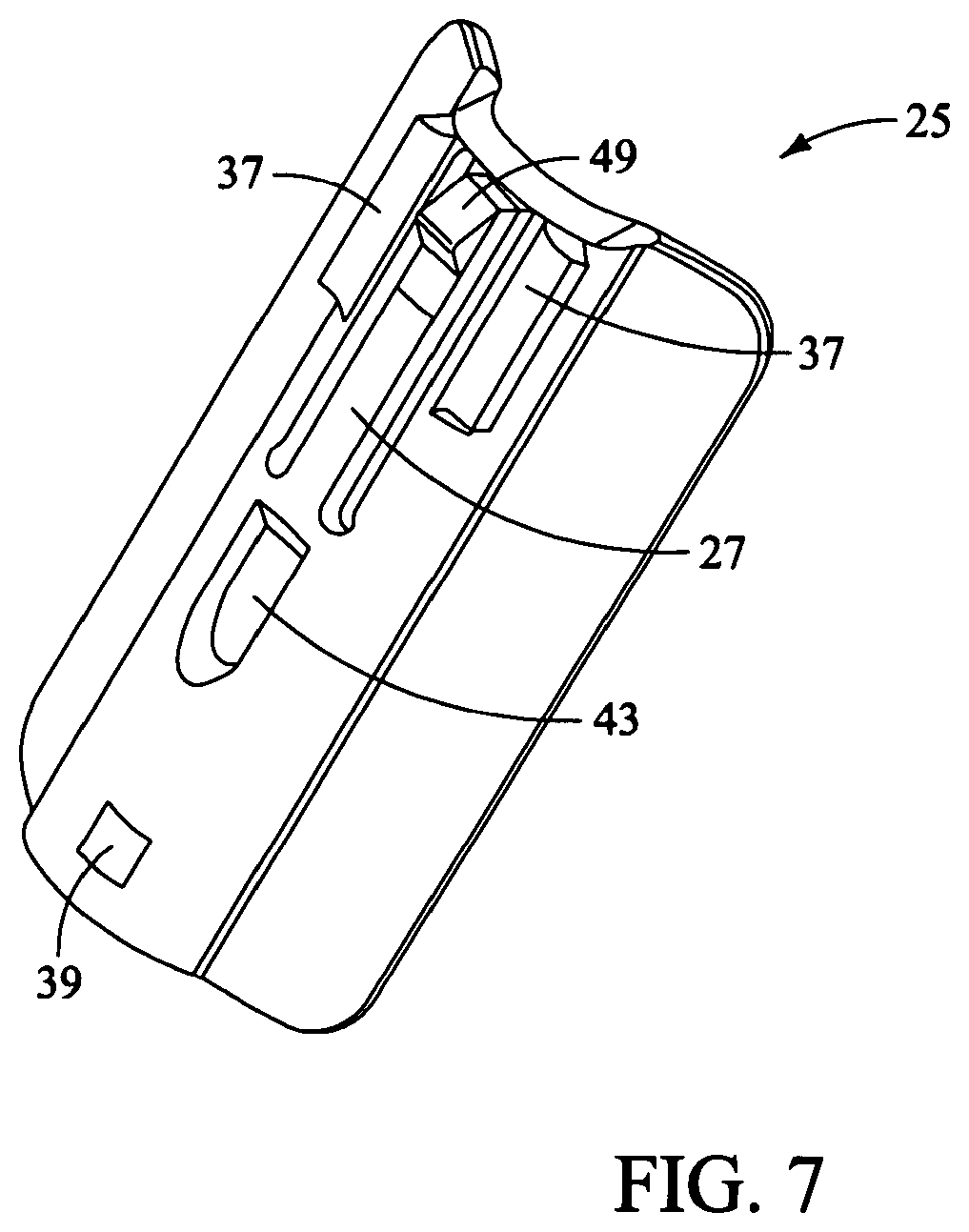
FIGS. 6-7 are perspective views illustrating the front and back of a wide retractor extender for use with one of a cephalad and caudal retractor blade according to the retractor of the present invention;
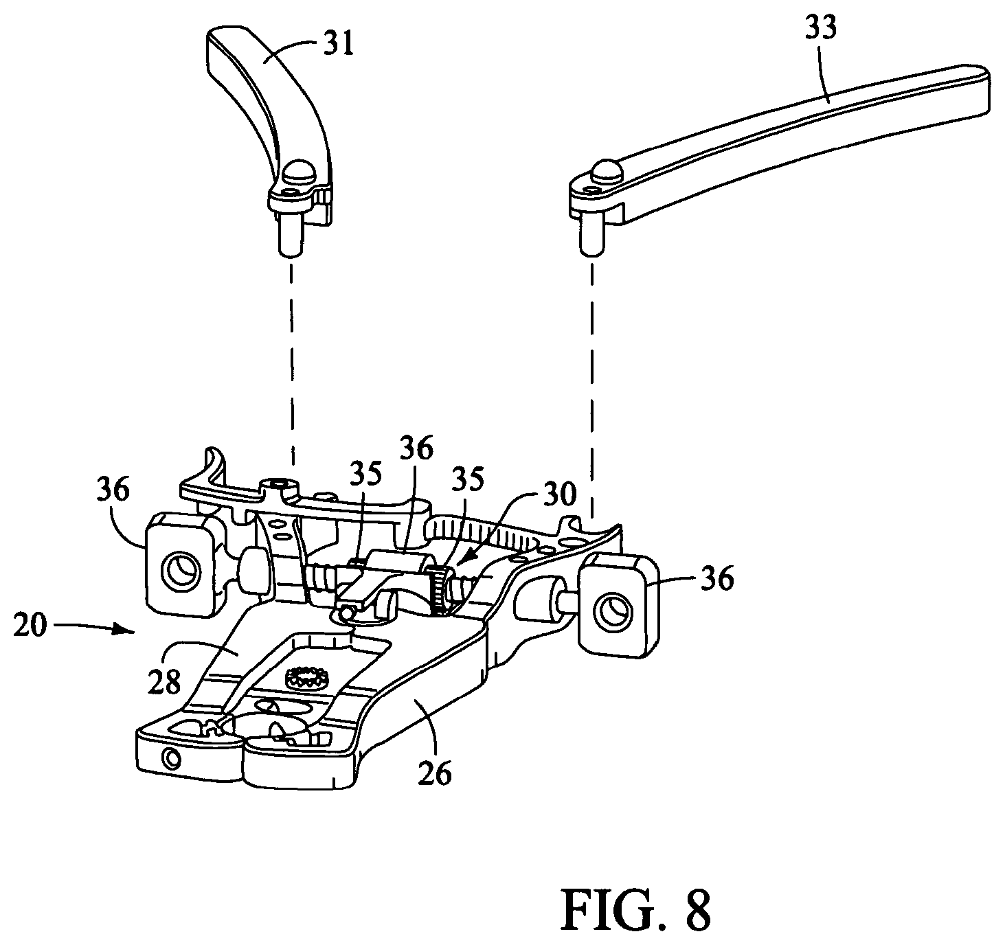
FIG. 8 is a perspective, partially exploded view of the retractor assembly of the present invention, without the retractor blades;
FIG. 9 is a perspective view illustrating the components and use of an initial distraction assembly (i.e. K-wire, an initial dilating cannula with handle, and a split-dilator housed within the initial dilating cannula) forming part of the surgical access system according to the present invention, for use in distracting to a surgical target site (i.e. annulus);
FIG. 10 is a perspective view illustrating the K-wire and split-dilator of the initial distraction assembly with the initial dilating cannula and handle removed;
FIG. 11 is a posterior view of the vertebral target site illustrating the split-dilator of the present invention in use distracting in a generally cephalad-caudal fashion according to one aspect of the present invention;
FIG. 12 is a side view illustrating the use of a secondary distraction assembly (comprising a plurality of dilating cannulae over the K-wire) to further distract tissue between the skin of the patient and the surgical target site according to the present invention;
FIG. 13 is a side view of a retractor assembly according to the present invention, comprising a handle assembly having three (3) retractor blades extending there from (posterior, cephalad-most, and caudal-most) disposed over the secondary distraction assembly of FIG. 12 (shown in a first, closed position);
FIG. 14 is a side view of a retractor assembly according to the present invention, comprising a handle assembly having three (3) retractor blades extending there from (posterior, cephalad-most, and caudal-most) with the secondary distraction assembly of FIG. 12 removed and shim element introduced;
FIGS. 15-16 are perspective and top views, respectively, of the retractor assembly in a second, opened (i.e. retracted) position to thereby create an operative corridor to a surgical target site according to the present invention;
FIGS. 17-18 are perspective and side views, respectively, of the retractor assembly in the second, opened (i.e. retracted) position (with the secondary distraction assembly removed) and with the retractor extenders of FIGS. 4-5 and 6-7 coupled to the retractor according to the present invention.
FIG. 19 is a perspective view of an exemplary nerve monitoring system capable of performing nerve monitoring before, during and after the creating of an operative corridor to a surgical target site using the surgical access system in accordance with the present invention;
FIG. 20 is a block diagram of the nerve monitoring system shown in FIG. 19; and
FIGS. 21-22 are screen displays illustrating exemplary features and information communicated to a user during the use of the nerve monitoring system of FIG. 19.
FIGS. 23-50 illustrate a method for accessing a surgical target site in the spine using a substantially lateral, retroperitoneal approach.
DESCRIPTION OF THE PREFERRED EMBODIMENT
Illustrative embodiments of the invention are described below. In the interest of clarity, not all features of an actual implementation are described in this specification. It will of course be appreciated that in the development of any such actual embodiment, numerous implementation-specific decisions must be made to achieve the developers' specific goals, such as compliance with system-related and business-related constraints, which will vary from one implementation to another. Moreover, it will be appreciated that such a development effort might be complex and time-consuming, but would nevertheless be a routine undertaking for those of ordinary skill in the art having the benefit of this disclosure. It is furthermore to be readily understood that, although discussed below primarily within the context of spinal surgery, the surgical access system of the present invention may be employed in any number of anatomical settings to provide access to any number of different surgical target sites throughout the body. The surgical access system disclosed herein boasts a variety of inventive features and components that warrant patent protection, both individually and in combination.
The present invention involves accessing a surgical target site in a fashion less invasive than traditional "open" surgeries and doing so in a manner that provides access in spite of the neural structures required to be passed through (or near) in order to establish an operative corridor to the surgical target site. Generally speaking, the surgical access system of the present invention accomplishes this by providing a tissue distraction assembly and a tissue retraction assembly, both of which may be equipped with one or more electrodes for use in detecting the existence of (and optionally the distance and/or direction to) neural structures. In some embodiments, the surgical access system may be used access a surgical target site on the spine via a substantially lateral, retroperitoneal approach (as shown, for example, in FIGS. 23-50).
These electrodes are preferably provided for use with a nerve surveillance system such as, by way of example, the type shown and described in the co-pending and commonly assigned NeuroVision PCT Applications referenced above, the entire contents of which are expressly incorporated by reference as if set forth herein in their entirety. Generally speaking, this nerve surveillance system is capable of detecting the existence of (and optionally the distance and/or direction to) neural structures during the distraction and retraction of tissue by detecting the presence of nerves by applying a stimulation signal to such instruments and monitoring the evoked EMG signals from the myotomes associated with the nerves being passed by the distraction and retraction systems of the present invention. In so doing, the system as a whole (including the surgical access system of the present invention) may be used to form an operative corridor through (or near) any of a variety of tissues having such neural structures, particularly those which, if contacted or impinged, may otherwise result in neural impairment for the patient. In this fashion, the access system of the present invention may be used to traverse tissue that would ordinarily be deemed unsafe or undesirable, thereby broadening the number of manners in which a given surgical target site may be accessed.
The tissue distraction assembly of the present invention (comprising a K-wire, an initial dilator, and a split-dilator disposed within the initial dilator) is employed to distract the tissues extending between the skin of the patient and a given surgical target site (preferably along the posterior region of the target intervertebral disc). A secondary distraction assembly (i.e. a plurality of sequentially dilating cannulae) may optionally be employed after the initial distraction assembly to further distract the tissue. Once distracted, the resulting void or distracted region within the patient is of sufficient size to accommodate a tissue retraction assembly of the present invention. More specifically, the tissue retraction assembly (comprising a plurality of retractor blades extending from a handle assembly) may be advanced relative to the secondary distraction assembly such that the retractor blades, in a first, closed position, are advanced over the exterior of the secondary distraction assembly. At that point, the handle assembly may be operated to move the retractor blades into a second, open or "retracted" position to create an operative corridor to the surgical target site.
According to one aspect of the invention, following (or before) this retraction, a posterior shim element (which is preferably slideably engaged with the posterior retractor blade) may be advanced such that a distal shim extension in positioned within the posterior region of the disc space. If done before retraction, this helps ensure that the posterior retractor blade will not move posteriorly during the retraction process, even though the other retractor blades (i.e. cephalad-most and caudal-most) are able to move and thereby create an operative corridor. Fixing the posterior retractor blade in this fashion serves several important functions. First, the distal end of the shim element serves to distract the adjacent vertebral bodies, thereby restoring disc height. It also rigidly couples the posterior retractor blade in fixed relation relative to the vertebral bodies. The posterior shim element also helps ensure that surgical instruments employed within the operative corridor are incapable of being advanced outside the operative corridor, preventing inadvertent contact with the exiting nerve roots during the surgery. Once in the appropriate retracted state, the cephalad-most and caudal-most retractor blades may be locked in position and, thereafter, retractor extenders advanced therealong to prevent the ingress or egress of instruments or biological structures (i.e. nerves, vasculature, etc. . . . ) into or out of the operative corridor. Once the operative corridor is established, any of a variety of surgical instruments, devices, or implants may be passed through and/or manipulated within the operative corridor depending upon the given surgical procedure.
FIG. 1 illustrates a tissue retraction assembly 10 forming part of a surgical access system according to the present invention. The retraction assembly 10 includes a plurality of retractor blades extending from a handle assembly 20. By way of example only, the handle assembly 20 is provided with a first retractor blade 12, a second retractor blade 16, and a third retractor blade 18. The retractor assembly 10 is shown in a fully retracted or "open" configuration, with the retractor blades 12, 16, 18 positioned a distance from one another so as to form an operative corridor 15 there between and extending to a surgical target site (e.g. an annulus of an intervertebral disc). Although shown and described below with regard to the three-bladed configuration, it is to be readily appreciated that the number of retractor blades may be increased or decreased without departing from the scope of the present invention. Moreover, although described and shown herein, for example in FIGS. 1, 9-18, and 23-50, with reference to a generally lateral approach to a spinal surgical target site (with the first blade 12 being the "posterior" blade, the second blade 16 being the "cephalad-most" blade, and the third blade 18 being the "caudal-most" blade), it will be appreciated that the retractor assembly 10 of the present invention may find use in any number of different surgical approaches, including generally posterior, generally postero-lateral, generally anterior and generally antero-lateral.
The retractor blades 12, 16, 18 may be equipped with various additional features or components. By way of example only, posterior retractor blade 12 may be equipped with a shim element 22 (shown more clearly in FIGS. 2-3). Shim element 22 serves to distract the adjacent vertebral bodies (thereby restoring disc height), helps secure the retractor assembly 10 relative to the surgical target site, and forms a protective barrier to prevent the ingress or egress of instruments or biological structures (i.e. nerves, vasculature, etc. . . . ) into or out of the operative corridor. Each of the remaining retractor blades (cephalad-most blade 16 and caudal-most blade 18) may be equipped with a retractor extender, such as the narrow retractor extender 24 shown in FIGS. 4-5 or the wide retractor extender 25 shown in FIGS. 6-7. The retractor extenders 24/25 extend from the cephalad-most and caudal-most retractor blades 16, 18 to form a protective barrier to prevent the ingress or egress of instruments or biological structures (i.e. nerves, vasculature, etc. . . . ) into or out of the operative corridor 15.
According to the present invention, any or all of the retractor blades 12, 16, 18, the shim element 22 and/or the retractor extenders 24/25 may be provided with one or more electrodes 39 (preferably at their distal regions) equipped for use with a nerve surveillance system, such as, by way of example, the type shown and described in the NeuroVision PCT Applications. Each of the shim element 22 and/or the retractor extenders 24/25 may also be equipped with a mechanism to selectively and releasably engage with the respective retractor blades 12, 16, 18. By way of example only, this may be accomplished by configuring the shim element 22 and/or the retractor extenders 24/25 with a tab element 27 capable of engaging with corresponding rachet-like grooves (shown at 29 in FIG. 1) along the inner-facing surfaces of the retractor blades 12, 16, 18. Each of the shim element 22 and/or the retractor extenders 24/25 is provided with a pair of engagement elements 37 having, by way of example only, a generally dove-tailed cross-sectional shape. The engagement elements 37 are dimensioned to engage with receiving portions on the respective retractor blades 12, 16, 18. In a preferred embodiment, each of the shim element 22 and/or the retractor extenders 24/25 are provided with an elongate slot 43 for engagement with an insertion tool (not shown). Each tab member 27 is also equipped with an enlarged tooth element 49 which engages within corresponding grooves 29 provided along the inner surface of the retractor blades 12, 16, 18.
The handle assembly 20 may be coupled to any number of mechanisms for rigidly registering the handle assembly 20 in fixed relation to the operative site, such as through the use of an articulating arm mounted to the operating table. The handle assembly 20 includes first and second arm members 26, 28 hingedly coupled via coupling mechanism shown generally at 30. The cephalad-most retractor blade 16 is rigidly coupled (generally perpendicularly) to the end of the first arm member 26. The caudal-most retractor blade 18 is rigidly coupled (generally perpendicularly) to the end of the second arm member 28. The posterior retractor blade 12 is rigidly coupled (generally perpendicularly to) a translating member 17, which is coupled to the handle assembly 20 via a linkage assembly shown generally at 14. The linkage assembly 14 includes a roller member 34 having a pair of manual knob members 36 which, when rotated via manual actuation by a user, causes teeth 35 on the roller member 34 to engage within ratchet-like grooves 37 in the translating member 17. Thus, manual operation of the knobs 36 causes the translating member 17 to move relative to the first and second arm members 26, 28.
Through the use of handle extenders 31, 33 (FIG. 8), the arms 26, 28 may be simultaneously opened such that the cephalad-most and caudal-most retractor blades 16, 18 move away from one another. In this fashion, the dimension and/or shape of the operative corridor 15 may be tailored depending upon the degree to which the translating member 17 is manipulated relative to the arms 26, 28. That is, the operative corridor 15 may be tailored to provide any number of suitable cross-sectional shapes, including but not limited to a generally circular cross-section, a generally ellipsoidal cross-section, and/or an oval cross-section. Optional light emitting devices 39 may be coupled to one or more of the retractor blades 12, 16, 18 to direct light down the operative corridor 15.
FIG. 9 illustrates an initial distraction assembly 40 forming part of the surgical access system according to the present invention. The initial distraction assembly 40 includes a K-wire 42, an initial dilating cannula 44 with handle 46, and a split-dilator 48 housed within the initial dilating cannula 44. In use, the K-wire 42 and split-dilator 48 are disposed within the initial dilating cannula 44 and the entire assembly 40 advanced through the tissue towards the surgical target site (i.e. annulus). One exemplary method for advancing an initial dilator towards a spinal target site is described in more detail later in connection with FIGS. 23-50. Again, this is preferably accomplished while employing the nerve detection and/or direction features described above. After the initial dilating assembly 40 is advanced such that the distal ends of the split-dilator 48 and initial dilator 44 are positioned within the disc space (FIG. 9), the initial dilator 44 and handle 46 are removed (FIG. 10) to thereby leave the split-dilator 48 and K-wire 42 in place. As shown in FIG. 11, the split-dilator 48 is thereafter split such that the respective halves 48a, 48b are separated from one another to distract tissue in a generally cephalad-caudal fashion relative to the target site. The split dilator 48 may thereafter be relaxed (allowing the dilator halves 48a, 48b to come together) and rotated such that the dilator halves 48a, 48b are disposed in the anterior-posterior plane. Once rotated in this manner, the dilator halves 48a, 48b are again separated to distract tissue in a generally anterior-posterior fashion. Each dilator halve 48a, 48b may be, according to the present invention, provided with one or more electrodes (preferably at their distal regions) equipped for use with a nerve surveillance system, such as, by way of example, the type shown and described in the NeuroVision PCT Applications.
Following this initial distraction, a secondary distraction may be optionally undertaken, such as via a sequential dilation system 50 as shown in FIG. 12. According to the present invention, the sequential dilation system 50 may include the K-wire 42, the initial dilator 44, and one or more supplemental dilators 52, 54 for the purpose of further dilating the tissue down to the surgical target site. Once again, each component of the secondary distraction assembly 50 (namely, the K-wire 42, the initial dilator 44, and the supplemental dilators 52, 54 may be, according to the present invention, provided with one or more electrodes (preferably at their distal regions) equipped for use with a nerve surveillance system, such as, by way of example, the type shown and described in the NeuroVision PCT Applications.
As shown in FIG. 13, the retraction assembly 10 of the present invention is thereafter advanced along the exterior of the sequential dilation system 50. This is accomplished by maintaining the retractor blades 12, 16, 18 in a first, closed position (with the retractor blades 12-16 in generally abutting relation to one another). Once advanced to the surgical target site, the sequential dilation assembly 50 may be removed and the shim element 22 engaged with the posterior retractor blade 12 such that the distal end thereof extends into the disc space as shown in FIG. 14. At this point, the handle assembly 20 may be operated to move the retractor blades 16, 18 into a second, open or "retracted" position as shown generally in FIGS. 15-16. As one can see, the posterior retractor blade 12 is allowed to stay in the same general position during this process, such that the cephalad-most and caudal-most retractor blades 14, 16 move away from the posterior retractor blade 12. At this point, the narrow and wide retractor extenders 24, 25 may be engaged with the caudal-most retractor blade 18 and cephalad-most retractor blade 16, respectively, as shown in FIGS. 17-18.
As mentioned above, any number of distraction components and/or retraction components (including but not limited to those described herein) may be equipped to detect the presence of (and optionally the distance and/or direction to) neural structures during the steps tissue distraction and/or retraction. This is accomplished by employing the following steps: (1) one or more stimulation electrodes are provided on the various distraction and/or retraction components; (2) a stimulation source (e.g. voltage or current) is coupled to the stimulation electrodes; (3) a stimulation signal is emitted from the stimulation electrodes as the various components are advanced towards or maintained at or near the surgical target site; and (4) the patient is monitored to determine if the stimulation signal causes muscles associated with nerves or neural structures within the tissue to innervate. If the nerves innervate, this may indicate that neural structures may be in close proximity to the distraction and/or retraction components.
Neural monitoring may be accomplished via any number of suitable fashions, including but not limited to observing visual twitches in muscle groups associated with the neural structures likely to found in the tissue, as well as any number of monitoring systems, including but not limited to any commercially available "traditional" electromyography (EMG) system (that is, typically operated by a neurophysiologist). Such monitoring may also be carried out via the surgeon-driven EMG monitoring system shown and described in the following commonly owned and co-pending NeuroVision PCT Applications referenced above. In any case (visual monitoring, traditional EMG and/or surgeon-driven EMG monitoring), the access system of the present invention may advantageously be used to traverse tissue that would ordinarily be deemed unsafe or undesirable, thereby broadening the number of manners in which a given surgical target site may be accessed. For example, the surgical access system may be advantageously used to traverse tissue through the retroperitoneal space and the psoas muscle during a substantially lateral, retroperitoneal approach to the lumbar spine, as shown in FIGS. 23-50.
FIGS. 19-20 illustrate, by way of example only, a monitoring system 120 of the type disclosed in the NeuroVision PCT Applications suitable for use with the surgical access system 10 of the present invention. The monitoring system 120 includes a control unit 122, a patient module 124, and an EMG harness 126 and return electrode 128 coupled to the patient module 124, and a cable 132 for establishing electrical communication between the patient module 124 and the surgical access system of the present invention (retractor assembly 10 of FIG. 1 and distraction assemblies 40, 50 of FIGS. 9-12). More specifically, this electrical communication can be achieved by providing, by way of example only, a hand-held stimulation controller 152 capable of selectively providing a stimulation signal (due to the operation of manually operated buttons on the hand-held stimulation controller 152) to one or more connectors 156a, 156b, 156c. The connectors 156a, 156b, 156c are suitable to establish electrical communication between the hand-held stimulation controller 152 and (by way of example only) the stimulation electrodes on the K-wire 42, the dilators 44, 48, 52, 54, the retractor blades 12, 16, 18 and/or the shim members 22, 24, 25 (collectively "surgical access instruments").
In order to use the monitoring system 120, then, these surgical access instruments must be connected to the connectors 156a, 156b and/or 156c, at which point the user may selectively initiate a stimulation signal (preferably, a current signal) from the control unit 122 to a particular surgical access instruments. Stimulating the electrode(s) on these surgical access instruments before, during and/or after establishing operative corridor will cause nerves that come into close or relative proximity to the surgical access instruments to depolarize, producing a response in a myotome associated with the innervated nerve.
The control unit 122 includes a touch screen display 140 and a base 142, which collectively contain the essential processing capabilities (software and/or hardware) for controlling the monitoring system 120. The control unit 122 may include an audio unit 118 that emits sounds according to a location of a surgical element with respect to a nerve. The patient module 124 is connected to the control unit 122 via a data cable 144, which establishes the electrical connections and communications (digital and/or analog) between the control unit 122 and patient module 124. The main functions of the control unit 122 include receiving user commands via the touch screen display 140, activating stimulation electrodes on the surgical access instruments, processing signal data according to defined algorithms, displaying received parameters and processed data, and monitoring system status and report fault conditions. The touch screen display 140 is preferably equipped with a graphical user interface (GUI) capable of communicating information to the user and receiving instructions from the user. The display 140 and/or base 142 may contain patient module interface circuitry (hardware and/or software) that commands the stimulation sources, receives digitized signals and other information from the patient module 124, processes the EM
D00000
D00001
D00002
D00003
D00004
D00005
D00006
D00007
D00008
D00009
D00010
D00011
D00012

D00013

D00014

D00015

D00016

D00017

D00018

D00019

D00020

D00021

D00022
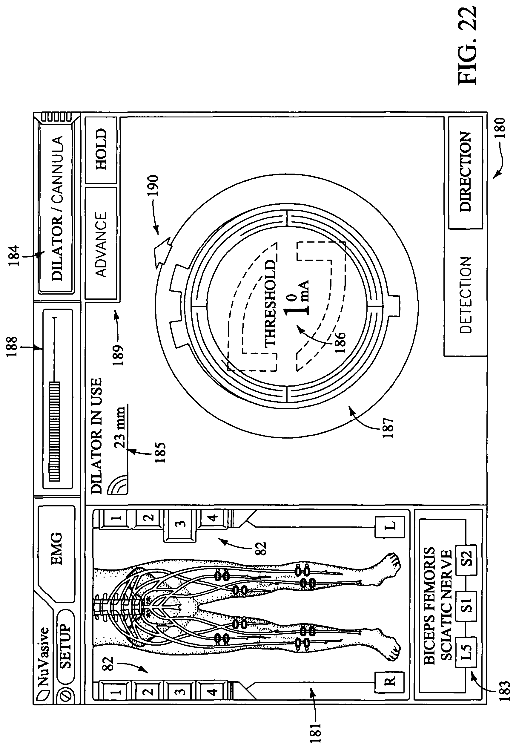
D00023

D00024

D00025

D00026
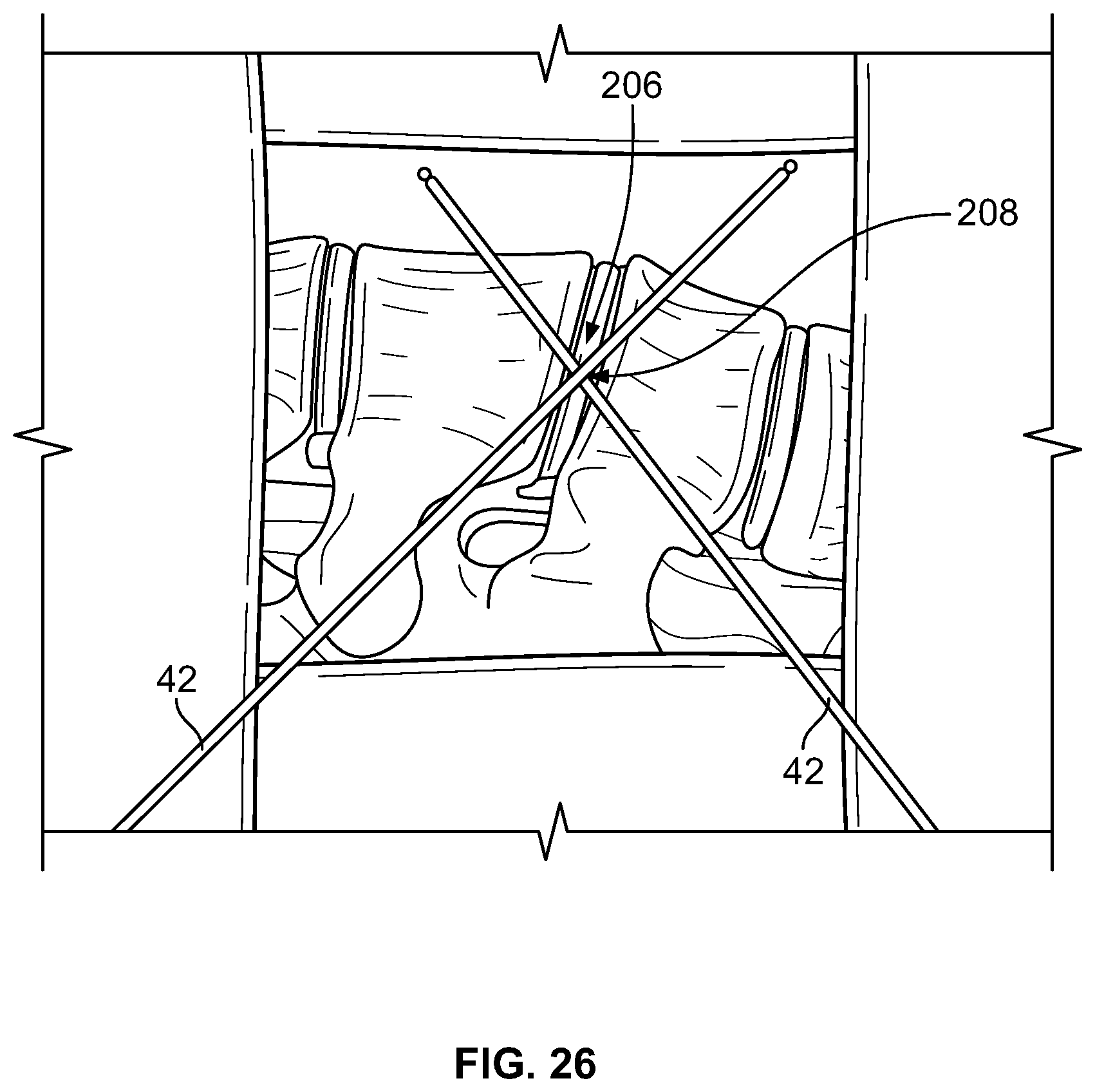
D00027

D00028

D00029
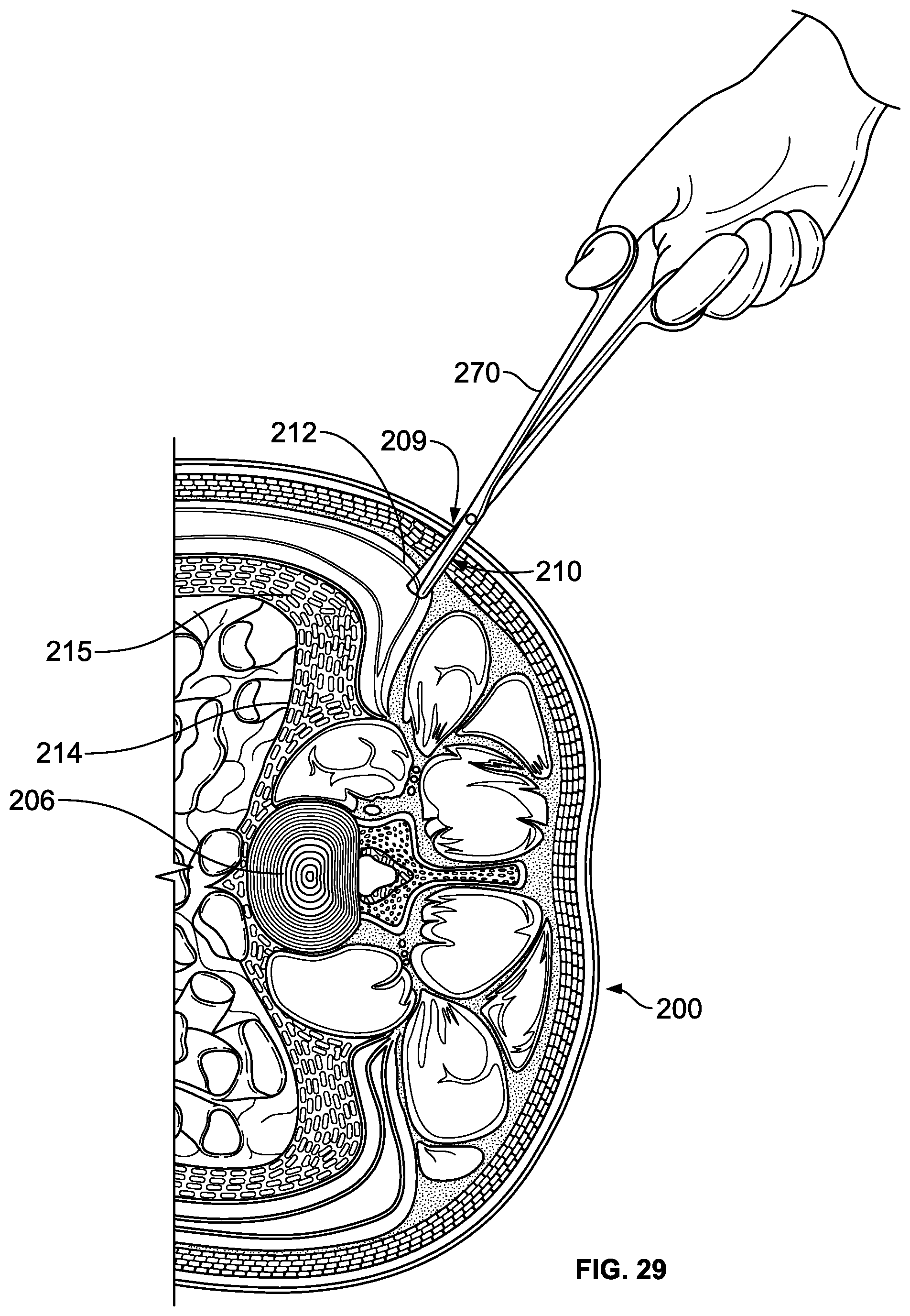
D00030

D00031
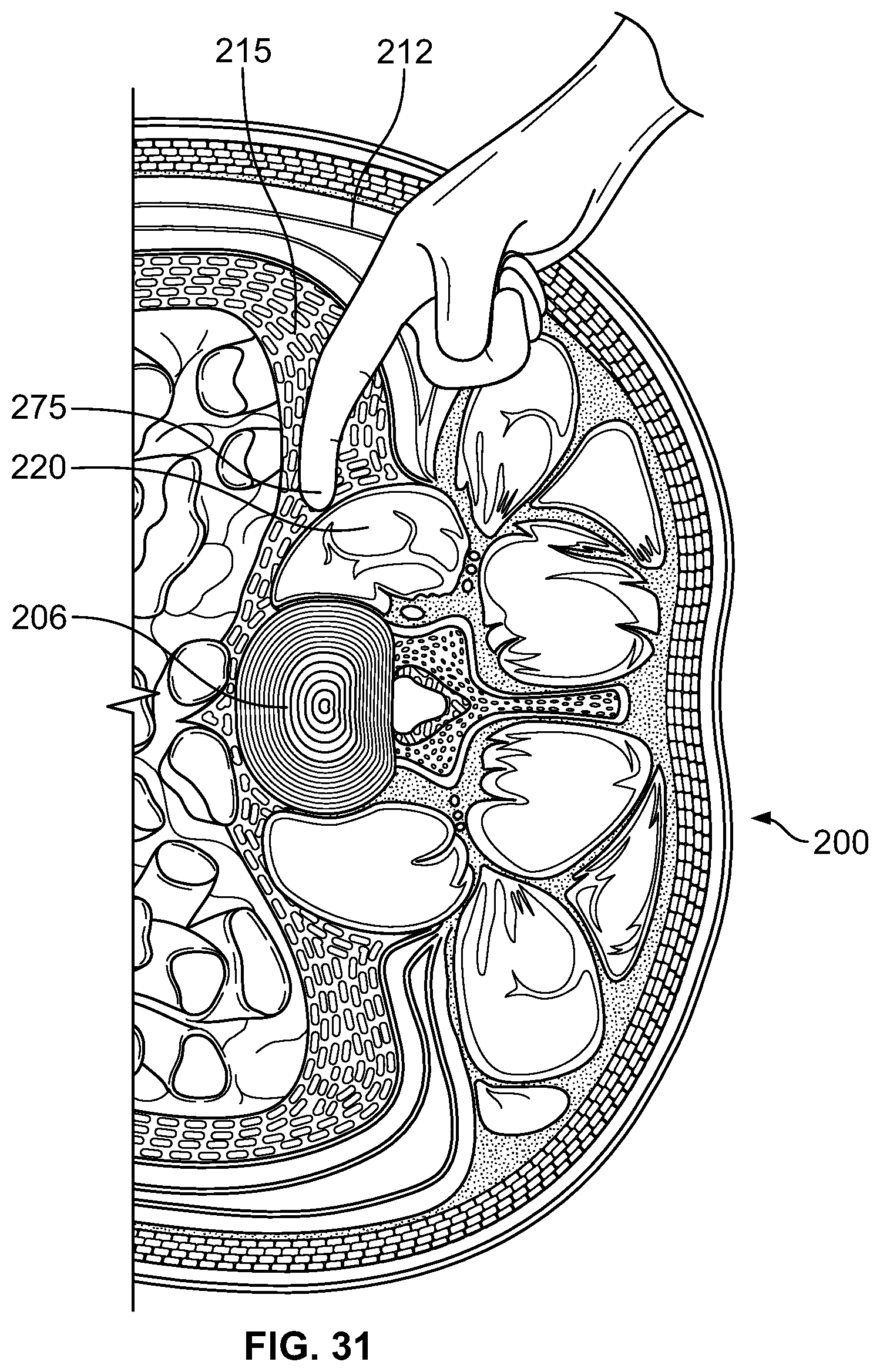
D00032
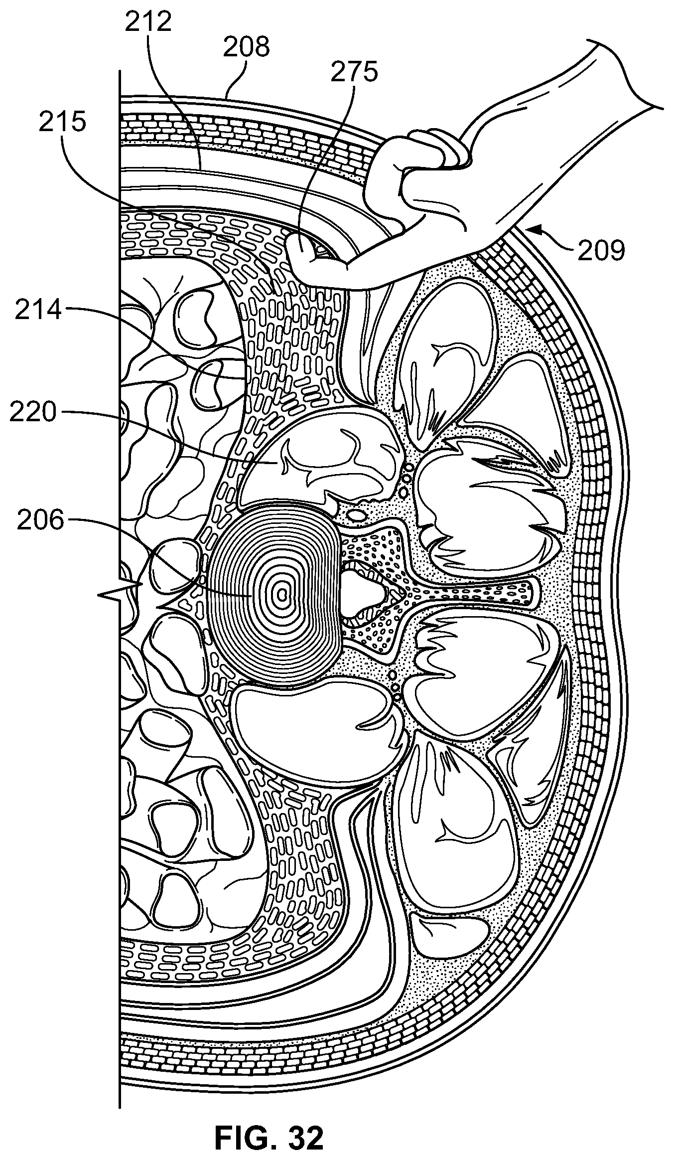
D00033

D00034

D00035

D00036

D00037

D00038
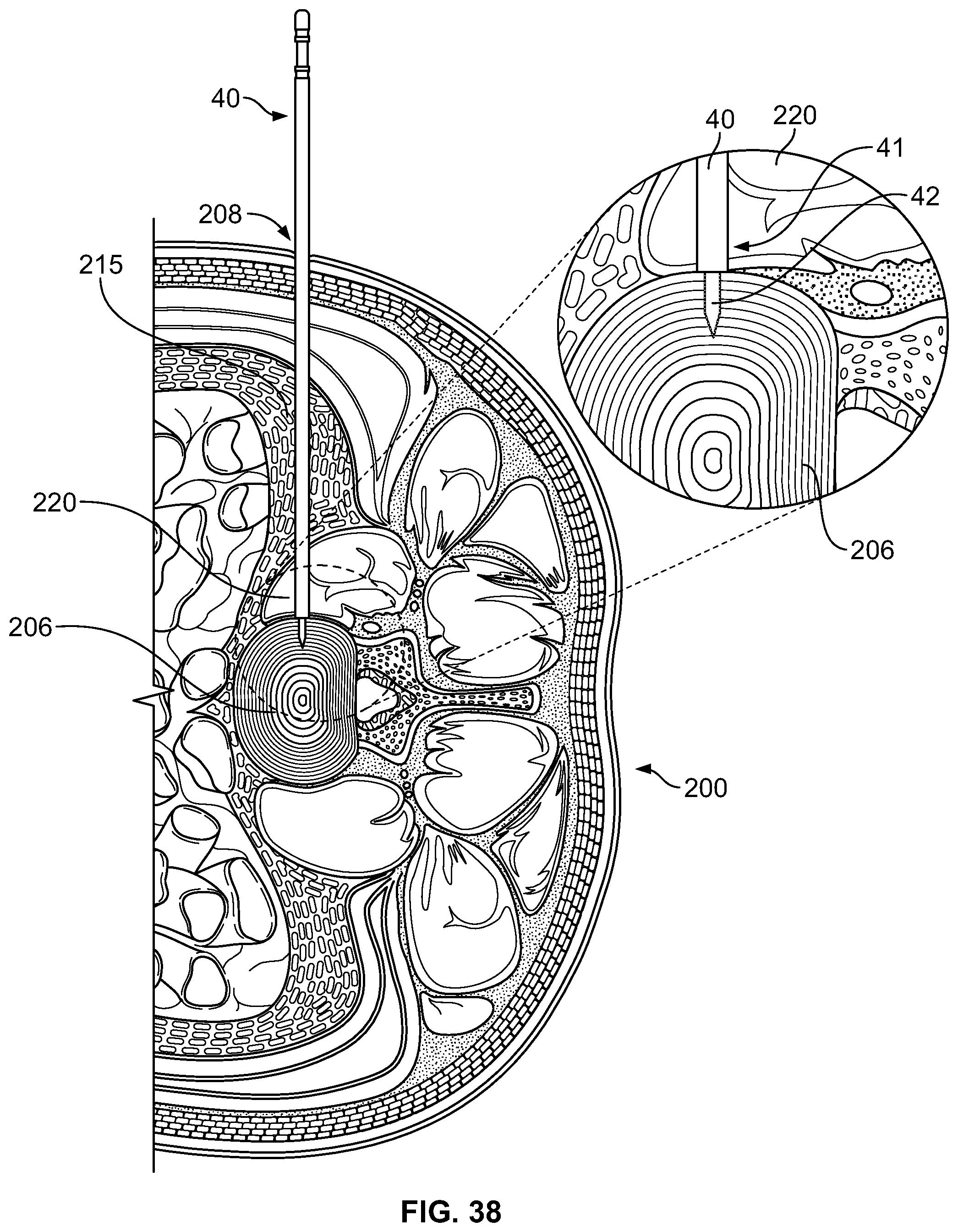
D00039

D00040
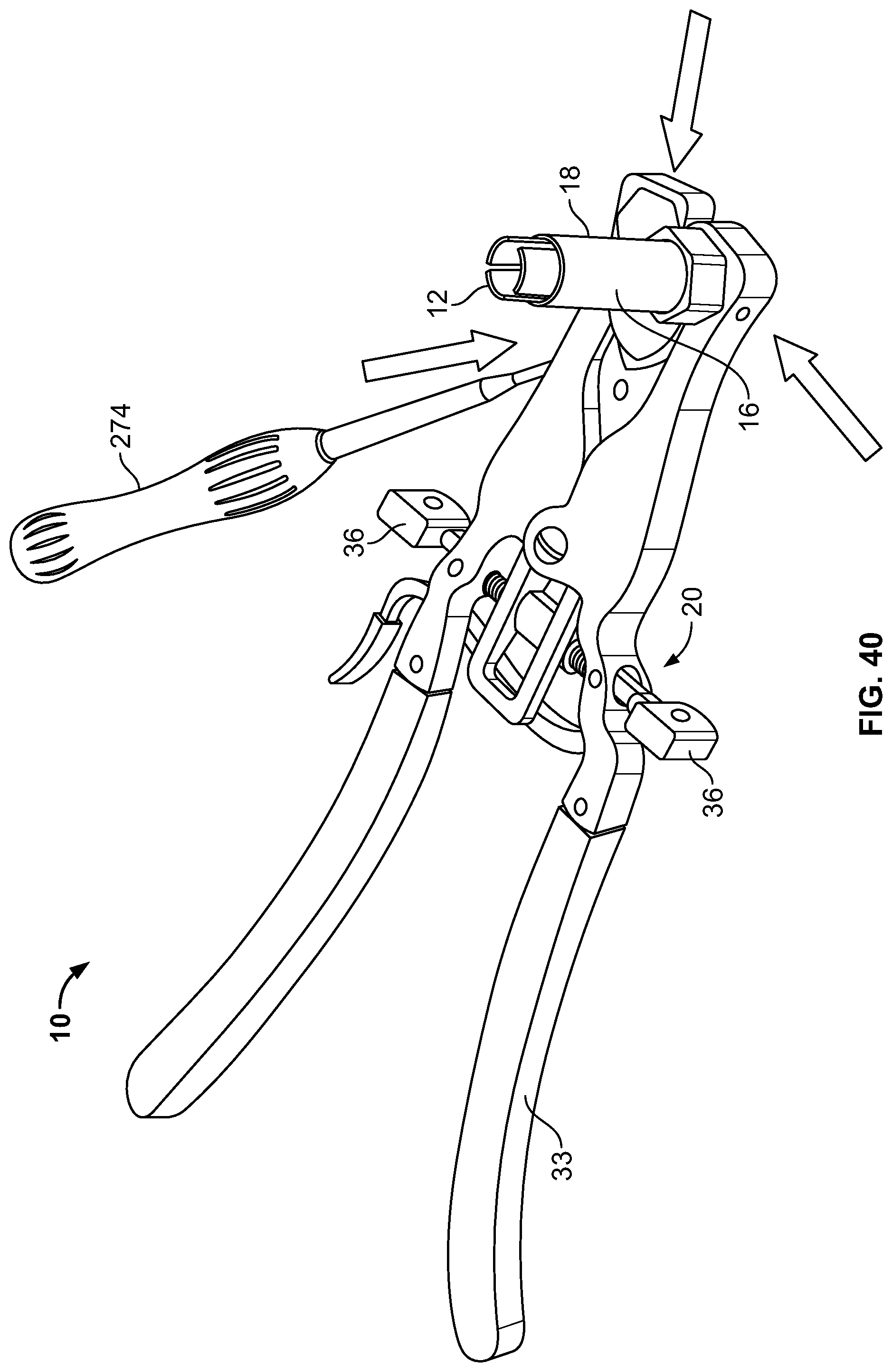
D00041
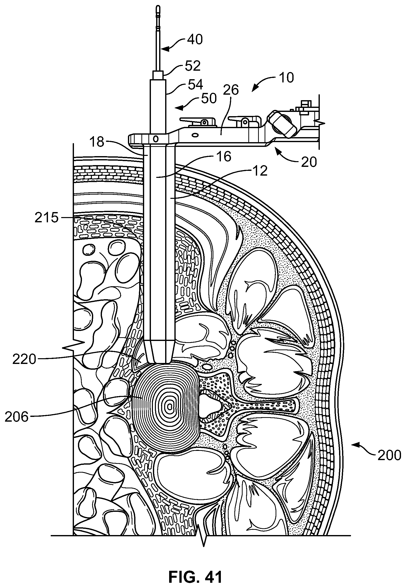
D00042

D00043

D00044
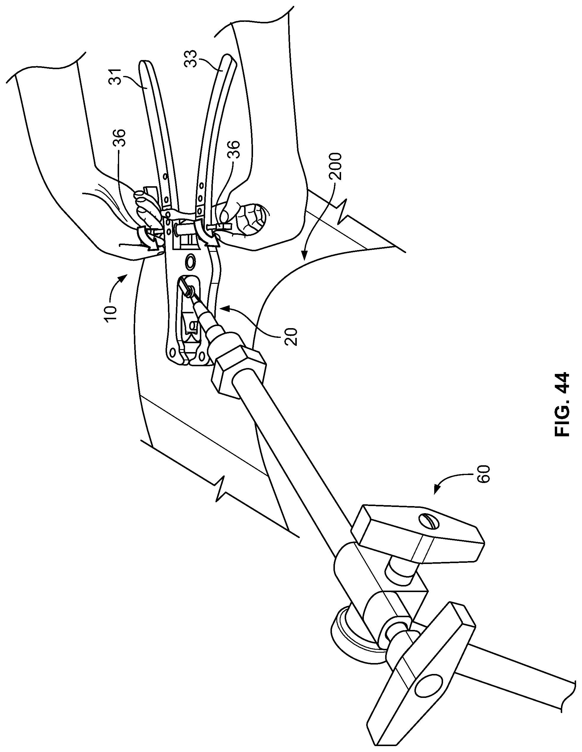
D00045
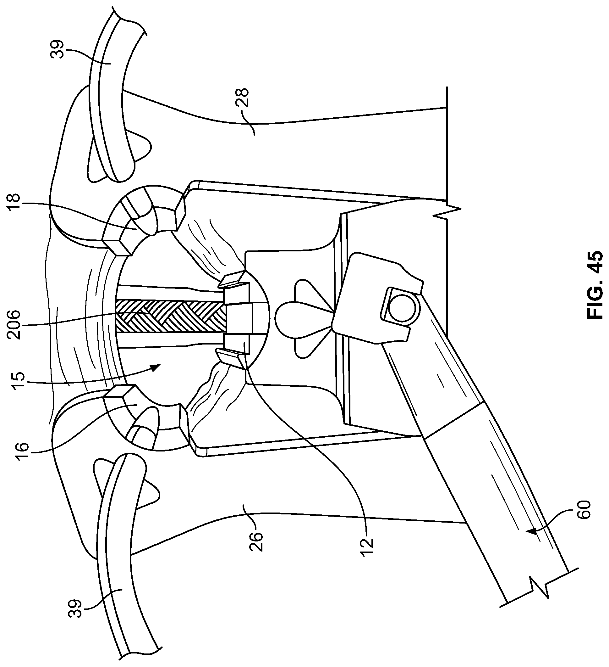
D00046

D00047

D00048

D00049

D00050

XML
uspto.report is an independent third-party trademark research tool that is not affiliated, endorsed, or sponsored by the United States Patent and Trademark Office (USPTO) or any other governmental organization. The information provided by uspto.report is based on publicly available data at the time of writing and is intended for informational purposes only.
While we strive to provide accurate and up-to-date information, we do not guarantee the accuracy, completeness, reliability, or suitability of the information displayed on this site. The use of this site is at your own risk. Any reliance you place on such information is therefore strictly at your own risk.
All official trademark data, including owner information, should be verified by visiting the official USPTO website at www.uspto.gov. This site is not intended to replace professional legal advice and should not be used as a substitute for consulting with a legal professional who is knowledgeable about trademark law.