Stabilizing device for a small arms weapon
Faifer
U.S. patent number 10,627,189 [Application Number 16/253,176] was granted by the patent office on 2020-04-21 for stabilizing device for a small arms weapon. The grantee listed for this patent is Sagi Faifer. Invention is credited to Sagi Faifer.


View All Diagrams
| United States Patent | 10,627,189 |
| Faifer | April 21, 2020 |
Stabilizing device for a small arms weapon
Abstract
A stabilizing device for a small arms weapon is disclosed. The stabilizing device may include a housing, a starboard side support member, a port side support member, and a primary hinge pin. The primary hinge pin, the starboard side support member, and the port side support member may form a joint. The stabilizing device further may include a webbing. The webbing may include one end secured to the starboard side support member and another end secured to the port side support member. The webbing may form a sling. The sling may be configured and dimensioned to rest on a body disposed between the first base and the second base. The body may be the forearm of an operator grasping the small arms weapon in a single hand. In one embodiment, the stabilizing device for a small arms weapon is connected to a pistol chassis.
| Inventors: | Faifer; Sagi (Mishmar Hashiva, IL) | ||||||||||
|---|---|---|---|---|---|---|---|---|---|---|---|
| Applicant: |
|
||||||||||
| Family ID: | 67298143 | ||||||||||
| Appl. No.: | 16/253,176 | ||||||||||
| Filed: | January 21, 2019 |
Prior Publication Data
| Document Identifier | Publication Date | |
|---|---|---|
| US 20190226798 A1 | Jul 25, 2019 | |
Related U.S. Patent Documents
| Application Number | Filing Date | Patent Number | Issue Date | ||
|---|---|---|---|---|---|
| 62620907 | Jan 23, 2018 | ||||
| 62620886 | Jan 23, 2018 | ||||
| Current U.S. Class: | 1/1 |
| Current CPC Class: | F41C 23/12 (20130101); F41A 3/72 (20130101); F41C 27/22 (20130101); F41C 23/04 (20130101); F41C 33/001 (20130101) |
| Current International Class: | F41C 23/12 (20060101); F41C 27/22 (20060101); F41C 33/00 (20060101); F41A 3/72 (20060101); F41C 23/04 (20060101) |
References Cited [Referenced By]
U.S. Patent Documents
| 22626 | January 1859 | Colt |
| 28433 | May 1860 | Alsop |
| 32003 | April 1861 | Savage |
| 46365 | February 1865 | Kinman |
| 202946 | April 1878 | Johnson |
| 223926 | January 1880 | Kinney |
| 287741 | October 1883 | Vickers, Jr. |
| 305537 | September 1884 | Schwatka |
| 461480 | October 1891 | Kellar |
| 517555 | April 1894 | Reed |
| 562487 | June 1896 | Quackenbush |
| 570145 | October 1896 | Pittavino |
| 593890 | November 1897 | Houston |
| 632098 | August 1899 | Capps |
| 681392 | August 1901 | Fugate |
| 723545 | March 1903 | Phillips |
| 815609 | March 1906 | Martin |
| 816074 | March 1906 | Cole |
| 899617 | September 1908 | Renfors et al. |
| 914675 | March 1909 | Renfors |
| 931328 | August 1909 | Marble |
| 1016695 | February 1912 | Kimmel |
| 1027556 | May 1912 | Marshall |
| 1111905 | September 1914 | Keeran |
| 1150763 | August 1915 | High |
| 1195055 | August 1916 | McNeal |
| 1196822 | September 1916 | Sues |
| 1206234 | November 1916 | Lovell |
| 1222264 | April 1917 | Cabanne |
| 1260285 | March 1918 | Cordell |
| 1266632 | May 1918 | Sachs |
| 1266633 | May 1918 | Sachs |
| 1276572 | August 1918 | Rodgers |
| 1283015 | October 1918 | Yung |
| 1315215 | September 1919 | Davidson |
| 1340127 | November 1920 | Welch |
| 1367996 | February 1921 | Sussman |
| 1371899 | March 1921 | Jenks et al. |
| 1431058 | October 1922 | Sutter |
| 1452123 | April 1923 | McCrudden |
| 1477445 | December 1923 | Petritsch |
| 1497794 | June 1924 | Saunders |
| 1519123 | December 1924 | Edwards |
| 1554556 | September 1925 | Camus |
| 1557865 | October 1925 | Neel et al. |
| 1569901 | January 1926 | Virdin |
| 1606609 | November 1926 | Wheeler, Jr. |
| 1671281 | May 1928 | Gorton |
| 1680186 | August 1928 | Von Frommer |
| 1877016 | September 1932 | Munson |
| 2139691 | December 1938 | Michal, Jr. |
| 2293128 | August 1942 | Fortin |
| 2424194 | July 1947 | Sampson et al. |
| 2433151 | December 1947 | Parsons |
| 2439137 | April 1948 | Keller |
| 2441487 | May 1948 | Howard |
| 2456280 | December 1948 | Humeston |
| 2495977 | January 1950 | Madsen |
| 2539008 | January 1951 | Brookhyser |
| 2611204 | September 1952 | Robinson, Jr. |
| 2683948 | July 1954 | Catron |
| 2789742 | April 1957 | De Salvo |
| 2873902 | February 1959 | Decker |
| 3011283 | December 1961 | Lunn et al. |
| 3100357 | August 1963 | Tellie |
| 3162966 | October 1964 | La Coss |
| 3184877 | May 1965 | Andrews |
| 3200528 | August 1965 | Christensen |
| 3209481 | October 1965 | Gilbert |
| 3235997 | February 1966 | Stoner |
| 3369316 | February 1968 | Miller |
| 3388494 | June 1968 | Kimball |
| 3442042 | May 1969 | Gilbert |
| 3553878 | January 1971 | Canon |
| 3609902 | October 1971 | Casull |
| 3641694 | February 1972 | Seidel et al. |
| 3648396 | March 1972 | Smith |
| 3685194 | August 1972 | Coon |
| 3740886 | June 1973 | Canon |
| 3782019 | January 1974 | Venturini |
| 3793759 | February 1974 | Deckard |
| 3798818 | March 1974 | Casul |
| D231828 | June 1974 | Canon |
| 3857323 | December 1974 | Ruger et al. |
| 3861273 | January 1975 | Seidel et al. |
| 4196742 | April 1980 | Owen |
| 4271623 | June 1981 | Beretta |
| 4291482 | September 1981 | Bresan |
| 4296566 | October 1981 | Campos |
| 4321765 | May 1982 | Gillum |
| 4397112 | August 1983 | York |
| 4398365 | August 1983 | Pokhis |
| 4513523 | April 1985 | Gal |
| 4515301 | May 1985 | A'Costa |
| 4579037 | April 1986 | Gillum |
| 4601123 | July 1986 | Swearengen et al. |
| 4640036 | February 1987 | Gal |
| 4660311 | April 1987 | Breitfeld et al. |
| 4674472 | June 1987 | Reis |
| 4735007 | April 1988 | Gal |
| 4735008 | April 1988 | Williams |
| 4776124 | October 1988 | Clifton |
| 4788785 | December 1988 | White |
| 4790095 | December 1988 | Campos |
| 4843749 | July 1989 | Griffith |
| 4858359 | August 1989 | Danz |
| 4989358 | February 1991 | Aronson et al. |
| 5018294 | May 1991 | McGuffee |
| 5056253 | October 1991 | Willumsen |
| 5092070 | March 1992 | Perkins |
| 5180874 | January 1993 | Troncoso, Jr. |
| 5351428 | October 1994 | Graham |
| 5379179 | January 1995 | Graves |
| 5445479 | August 1995 | Hillinger |
| 5479736 | January 1996 | Forrester |
| 5528846 | June 1996 | Baggett |
| 5761842 | June 1998 | Mantymaa |
| 5778588 | July 1998 | Allen, III et al. |
| 5778589 | July 1998 | Teague |
| 5819461 | October 1998 | Killian |
| D400954 | November 1998 | Ealovega |
| 5852253 | December 1998 | Baricos et al. |
| D411280 | June 1999 | Van Ek et al. |
| 5924233 | July 1999 | Stobel |
| 5930931 | August 1999 | Watson |
| 5930933 | August 1999 | Schleicher |
| 6016620 | January 2000 | Morgan |
| 6055760 | May 2000 | Cuson et al. |
| 6070809 | June 2000 | Price |
| 6112448 | September 2000 | Gray et al. |
| 6161741 | December 2000 | French |
| 6250009 | June 2001 | Leontuk |
| 6267335 | July 2001 | Barrett |
| 6318014 | November 2001 | Porter |
| 6324728 | December 2001 | Blankenheim |
| 6367187 | April 2002 | Bubits |
| 6560911 | May 2003 | Sharp |
| 6634128 | October 2003 | Vastag |
| 6678986 | January 2004 | Roush |
| 6729061 | May 2004 | DeJarnette, Jr. |
| 6789344 | September 2004 | Cain |
| 6829856 | December 2004 | Moorman |
| 6920713 | July 2005 | Love |
| 7028427 | April 2006 | Crawford |
| 7059502 | June 2006 | Johnson |
| 7065914 | June 2006 | Wagner, II |
| 7197844 | April 2007 | Benson |
| 7398616 | July 2008 | Weir |
| 7437847 | October 2008 | Mabry |
| 7552557 | June 2009 | Mabry |
| 7637882 | December 2009 | Carman, Jr. et al. |
| 7698848 | April 2010 | Bentley |
| 7849626 | December 2010 | Fluhr |
| D631122 | January 2011 | Domagtoy |
| 7909301 | March 2011 | Faifer |
| 7992336 | August 2011 | Phillips |
| 8051596 | November 2011 | Thomas et al. |
| 8061072 | November 2011 | Crose |
| 8091264 | January 2012 | Goertz |
| 8109026 | February 2012 | Bentley et al. |
| 8191301 | June 2012 | Hatfield |
| 8205374 | June 2012 | Lamm |
| 8438771 | May 2013 | Boone |
| 8448366 | May 2013 | Faifer |
| D683808 | June 2013 | Elkaim |
| 8549783 | October 2013 | Marquez |
| 8677669 | March 2014 | Vesligaj |
| D706896 | June 2014 | Bosco |
| 8776421 | July 2014 | Vesligaj |
| D716406 | October 2014 | Storey |
| 8869444 | October 2014 | Bosco |
| 8887432 | November 2014 | Oz |
| 9354012 | May 2016 | Faifer |
| 9354021 | May 2016 | Bosco |
| D764622 | August 2016 | Bosco |
| 9441898 | September 2016 | Istvanovics et al. |
| 9453699 | September 2016 | Barnett |
| 9459073 | October 2016 | Kloeppel |
| 9500439 | November 2016 | Dietrich et al. |
| D774618 | December 2016 | Bosco et al. |
| 9546843 | January 2017 | Sroufe et al. |
| D780279 | February 2017 | Bosco et al. |
| 9631893 | April 2017 | Glimer |
| D785744 | May 2017 | Bosco et al. |
| 9651335 | May 2017 | Denbleyker |
| 9664477 | May 2017 | Reavis, III |
| D792936 | July 2017 | Eitan et al. |
| D792937 | July 2017 | Eitan et al. |
| 9696110 | July 2017 | Hollis |
| 9746283 | August 2017 | Braun |
| D801467 | October 2017 | Rodgers et al. |
| 10165765 | January 2019 | Ching |
| 2002/0007579 | January 2002 | Bubits |
| 2002/0078617 | June 2002 | Percival |
| 2005/0115140 | June 2005 | Little |
| 2005/0235546 | October 2005 | Wonisch et al. |
| 2005/0262753 | December 2005 | Lahti |
| 2007/0017138 | January 2007 | Young |
| 2008/0060247 | March 2008 | Thomele et al. |
| 2009/0038200 | February 2009 | Keng |
| 2009/0049731 | February 2009 | Seuk |
| 2009/0282718 | November 2009 | Bartley |
| 2010/0084524 | April 2010 | Faifer |
| 2010/0154272 | June 2010 | Lamm |
| 2011/0030258 | February 2011 | Fiatikchi et al. |
| 2011/0107644 | May 2011 | Faifer |
| 2011/0131861 | June 2011 | Seuk |
| 2011/0154710 | June 2011 | Hatfield |
| 2012/0131829 | May 2012 | Fistikchi et al. |
| 2012/0266513 | October 2012 | Gnesda |
| 2013/0134286 | May 2013 | Yan |
| 2013/0167424 | July 2013 | Nail et al. |
| 2013/0185975 | July 2013 | Johnson |
| 2014/0053447 | February 2014 | Singh |
| 2014/0144061 | May 2014 | Bosco |
| 2014/0182181 | July 2014 | Bosco |
| 2015/0285577 | October 2015 | Faifer |
| 2016/0265872 | September 2016 | Tarazi |
| 2016/0282084 | September 2016 | Hollis |
| 2017/0082389 | March 2017 | Dix |
| 2017/0153084 | June 2017 | Tarazi |
| 2017/0248385 | August 2017 | Yehle |
| 2018/0058794 | March 2018 | Scalf |
| 2018/0216907 | August 2018 | Roberts |
| 2018/0224234 | August 2018 | Macy |
| 2019/0017777 | January 2019 | Wilson |
| 2019/0041156 | February 2019 | Beachli |
| 2019/0063869 | February 2019 | Keller |
| 2019/0195595 | June 2019 | Kielsmeier |
Attorney, Agent or Firm: Law Office of Arthur M. Antonelli, PLLC
Parent Case Text
CROSS-REFERENCE TO RELATED APPLICATIONS
This application claims the benefit of U.S. Provisional Application No. 62/620,907 filed on Jan. 23, 2018. Also, this application claims the benefit of U.S. Provisional Application No. 62/620,886 filed on Jan. 23, 2018. The disclosure of each of these applications is incorporated by reference herein in their entirety.
Claims
What is claimed is:
1. A stabilizing device for a small arms weapon comprising: an elongated member comprising a distal end for connecting to a small arms weapon, a a proximal end spaced from the distal end along a first longitudinal axis, and a housing near the proximal end of the elongated member, the housing comprising a front wall which comprises a front borehole, a rear wall which comprises a rear borehole, and a chamber disposed in the housing between the front wall and the rear wall; a primary hinge pin positioned in the front borehole and the rear bore hole; a starboard side support member which comprises a first leading element, and a first base, the first leading element comprising a first interior ring structure disposed about the primary hinge pin, and; a port side support member which comprises a second leading element, and a second base, the second leading element including a second interior ring structure disposed about the primary hinge pin such that the primary hinge pin, the first interior ring structure, and the second interior ring structure form a joint; a spring next to the first interior ring structure and the second interior ring structure, the spring being configured and dimensioned to bias the first base and the second base toward each other; and a webbing which comprises one end secured to the first base and another end secured to the second base, the webbing forming a sling between the starboard side support member and the port side support member, the sling being configured and dimensioned to rest on a body disposed between the first base and the second base.
2. A firearm apparatus comprising: a pistol chassis; and a stabilizing device for a small arms weapon of claim 1 connected to the pistol chassis.
Description
FIELD OF THE INVENTION
The invention generally relates to a stabilizing device for a small arms weapon. More particularly, the invention relates to a forearm supported stabilizing device for a firearm or pistol chassis.
BACKGROUND
Attachments for pistols are known in the related art. These attachments may be secured to a pistol to provide a platform for mounting tactical accessories. These attachments may be cumbersome to assemble, handle or deploy.
SUMMARY
Hence, the present disclosure is directed toward a forearm supported stabilizing device for a small arms weapon. More particularly, a stabilizing device for a small arms weapon is disclosed. The stabilizing device may include an elongated member which further may include a distal end for connecting to a small arms weapon, a proximal end spaced from the distal end along a first longitudinal axis, and a housing near the proximal end of the elongated member. The housing may include a front wall which may include a front borehole, a rear wall which may include a rear borehole, and a chamber disposed in the housing between the front wall and the rear wall. The stabilizing device further may include a primary hinge pin positioned in the front borehole and the rear bore hole.
Additionally, the stabilizing device may include a starboard side support member. The starboard side support member may include a first leading element and a first base. The first leading element may include a first interior ring structure disposed about the primary hinge pin. Also, the stabilizing device may include a port side support member. The port side support member may include a second leading element and a second base. The second leading element may include a second interior ring structure disposed about the primary hinge pin. The primary hinge pin, the first interior ring structure, and the second interior ring structure form a joint.
A spring may be disposed next to the first interior ring structure and the second interior ring structure. The spring may be configured and dimensioned to bias the first base and the second base toward each other.
The stabilizing device further may include a webbing. The webbing may include one end secured to the first base and another end secured to the second base. The webbing may form a sling between the starboard side support member and the port side support member. The sling may be configured and dimensioned to rest on a body disposed between the first base and the second base. The body may be the forearm of an operator grasping the small arms weapon in a single hand. In one embodiment, the stabilizing device for a small arms weapon is connected to a pistol chassis.
DESCRIPTION OF THE DRAWINGS
In the accompanying drawings, which form part of this specification and are to be read in conjunction therewith and in which like reference numerals are used to indicate like parts in the various views:
FIG. 1 is a perspective view of an exemplary small arms weapon and forearm supported stabilizing device, the forearm supported stabilizing device being in a deployed configuration;
FIG. 2 is a perspective view of part of the small arms weapon and the forearm supported stabilizing device of FIG. 1;
FIG. 3 is a top view of the forearm supported stabilizing device of FIG. 2;
FIG. 4 is a starboard side view of the forearm supported stabilizing device of FIG. 2;
FIG. 5 is a rear view of the small arms weapon and forearm supported stabilizing device of FIG. 1;
FIG. 6 is a partial sectional view of the device of FIG. 4 along line 6-6;
FIG. 7 is a partial sectional view of the device of FIG. 5 along line 7-7;
FIG. 8 is a perspective view of FIG. 6;
FIG. 9 is a cross sectional view of the device of FIG. 4 along line 9-9;
FIG. 10 is a cross-sectional view of the device of FIG. 4 along line 10-10 shown in a closed configuration;
FIG. 11 is a cross-sectional view of the device of FIG. 4 along line 10-10 shown in an open configuration;
FIG. 12 is an exploded view of the forearm supported stabilizing device of FIG. 2;
FIG. 13 is a cross-sectional view of the device of FIG. 4 along line 10-10 shown in a closed and stabilized configuration;
FIG. 14 is a cross-sectional view of the device of FIG. 13 in an open and stabilized configuration;
FIG. 15 is a port side view of the small arms weapon and forearm supported stabilizing device of FIG. 1 an open and stabilized configuration;
FIG. 16 is a perspective view of the small arms weapon and the forearm supported stabilizing device of FIG. 1, the forearm supported stabilizing device being in a folded configuration;
FIG. 17 is a partial sectional view of the coupling element and latching mechanism of FIG. 1, in a locked configuration;
FIG. 18 is an exploded view of the coupling element and latching mechanism of FIG. 1;
DESCRIPTION
FIG. 1 shows a perspective view of an exemplary small arms weapon 10 connected to an illustrative embodiment of a proximal accessory 12 that includes a forearm supported stabilizing device 14. Although the small arms weapon of FIG. 1 includes a pistol 16 and a chassis 18, other small arm weapons 10 may be substituted in their places and connected to the proximal accessory.
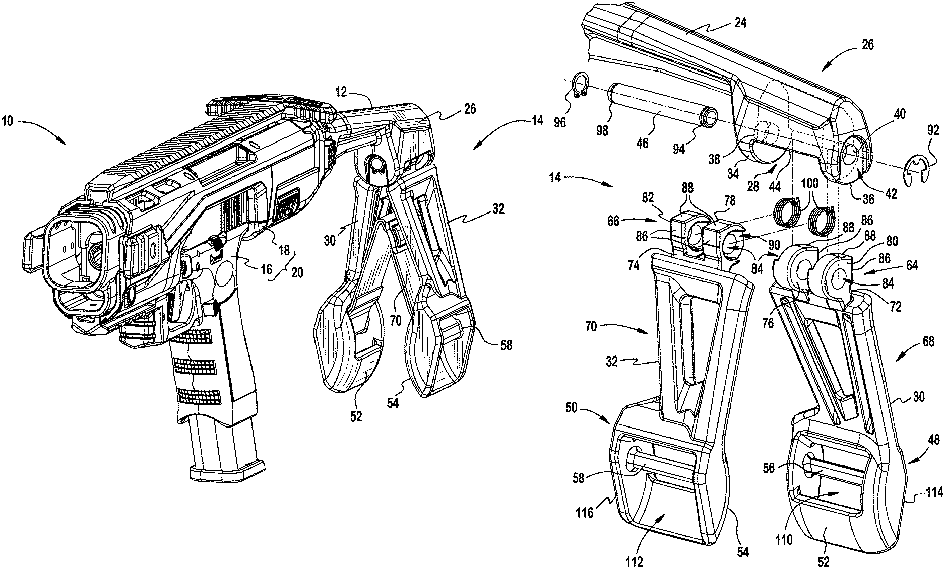
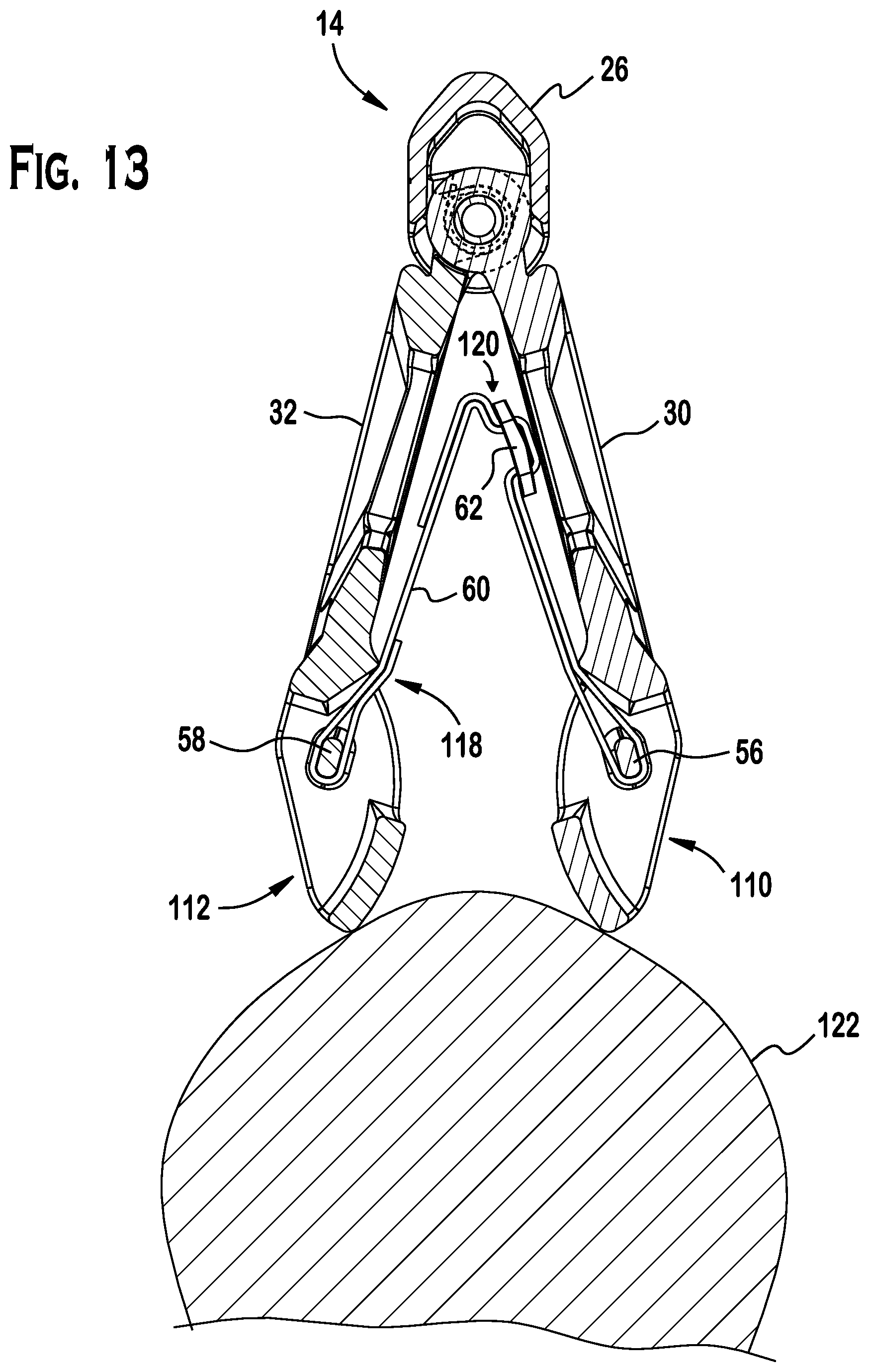
In the disclosed embodiment, the pistol 12 and the chassis 14 may be combined to form a firearm apparatus 20. The proximal accessory 12 may be secured to the firearm apparatus 15. The distal end 22 of the proximal accessory 12 may be integral to the small arms weapon or may be connected thereto. The proximal accessory 12 may further include a forearm supported stabilizing device 14. The forearm supported stabilizing device 14 may be adapted to engage with the forearm of an operator of the small arms weapon 10 to aid in positioning (see e.g., FIG. 13) or stabilizing (see e.g., FIG. 14) the small arms weapon during use (see e.g., FIG. 15). Referring to FIG. 2, the forearm supported stabilizing device 14 may be spaced from the distal end 22 of the proximal accessory by a stein 24. The stem may further include a housing 26 that includes a chamber 28 (see e.g., FIG. 12) which receives a starboard side support member 30 and a port side support member 32.
Referring to FIG. 12, the housing may include a front wall 34 and a rear wall 36. The chamber may be situated between the front wall and the rear wall. The front wall 34 may include a front borehole 38, and the rear wall 36 may include a rear borehole 40. The front borehole may be aligned with the rear borehole. The rear wall 36 may include a recess 42 around the rear borehole. Further, the housing 26 may define an opening 44 to the chamber between the rear wall and the front wall. The support members 30, 32 may be interposed in the chamber 28 and connected by a primary hinge pin 46 that is disposed in the front borehole and the rear borehole. Each of the support members 30, 32 may include a base 48, 50. Each base 48, 50 may include an inner surface 52, 54 and an anchor 56, 58. Referring to FIG. 4 and FIG. 5, the forearm supported stabilizing device 14 may include a webbing (or strap) 60. One end of the webbing 60 may be secured to or around the port side anchor 58 and the opposite end of the webbing 60 may be secured to or around the starboard side anchor 56. The webbing may have an effective length between the support members. Also, the webbing may include a mechanism (e.g., a buckle 62) which selectively allows for the effective length of the webbing to be increased or decreased.
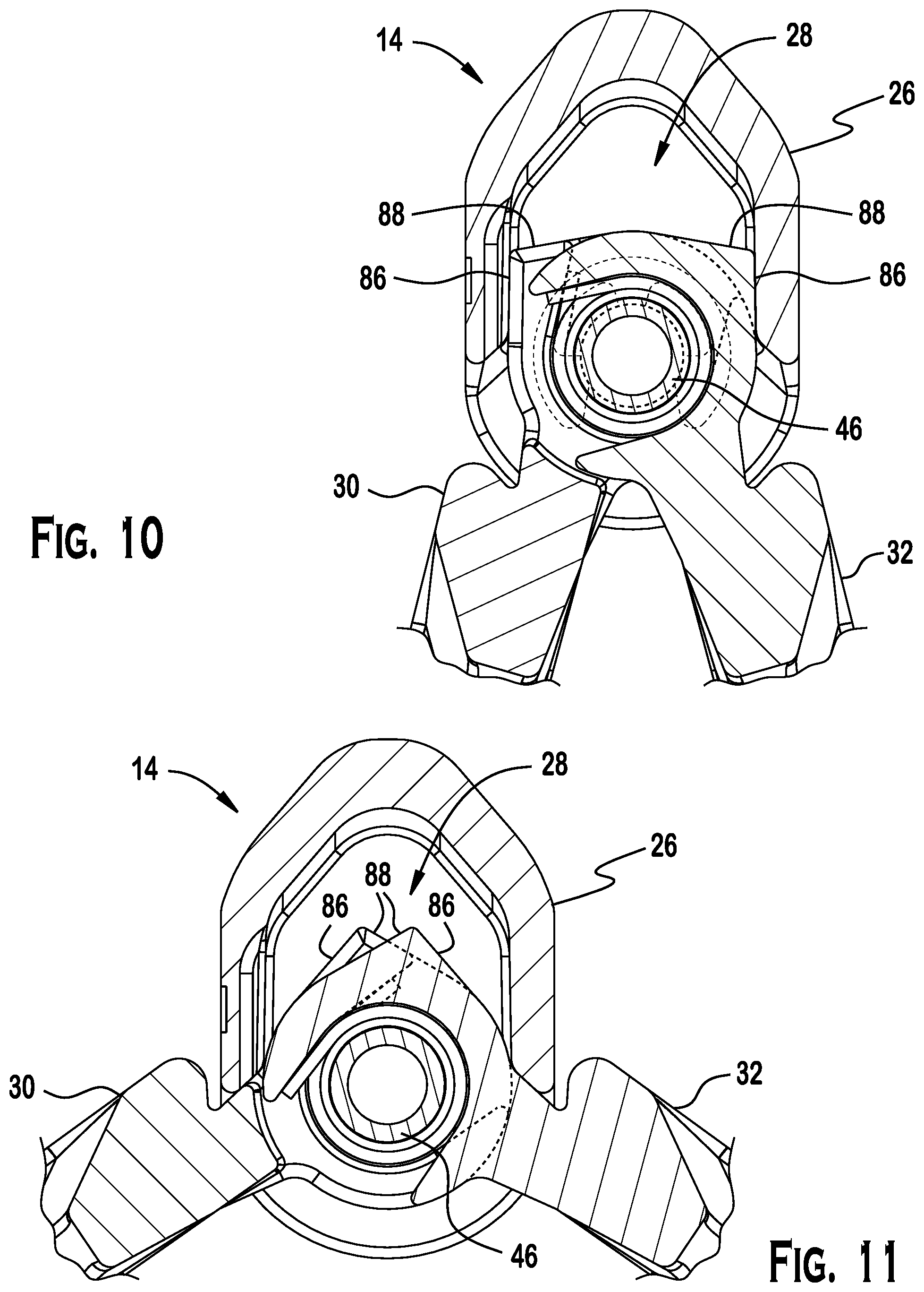
Referring to FIG. 12, each support member 30, 32 may include a head 64, 66 that is spaced from the base 48, 50, as well as a frame 68, 70 that connects the head to the base. The head may include a leading element 72, 74. The leading element may include an interior ring structure 76, 78 and an exterior ring structure 80, 82. The interior ring structure and an exterior ring structure may include a bore 84, a side recess 90, and two flat faces 86, 88. The two flat faces may intersect to form a corner. In one example, the two flat faces may form an oblique angle. In another example, the two flat faces may form a right angle. Referring to FIG. 11, one face 88 may define a blocking surface that limits rotation of the base away from the base of the other support member. Referring to FIG. 10, the other face 86 may define another blocking surface that limits rotation of the base toward the base of the other support member.
Referring to FIG. 12, each interior ring structure and exterior ring structure may be received on the primary hinge pin 46. For example, the primary hinge pin 46 may be inserted in the front borehole 38, the respective bores 84 in the leading elements 72, 74 of the starboard side support member 30 and the port side support member 32, as well as in the rear borehole 40. The primary hinge pin may be secured on one side of the housing by a ring clip 92. The ring clip 92 may mate with a circumferential groove 94 in primary hinge pin. Similarly, the opposite end of the primary hinge pin may be secured on the other side of the housing by a retaining ring 96. The retaining ring may interlock with a circumferential groove 98 on the primary hinge pin 46.
Referring to FIGS. 6, 7 and 8, the side recesses 90 on the leading element 72 of the starboard support member may face the side recesses 90 on the leading element 74 of the port side support member. A torsion spring 100 may be positioned on the primary hinge pin between the respective recesses 90 of the starboard side and port side support members. The torsion spring(s) 100 may be configured and dimensioned to bias the bases 48, 50 of the respective support members toward each other (see e.g., FIG. 5). Moreover, the torsion spring (s) may bias blocking surface(s) 86 of the respective leading elements against the housing to stop inward rotation of each base (see e.g., FIGS. 9 and 10). Such an orientation of the support arm stabilizing device 14 may be identified as a ready configuration.
Referring to FIG. 11, work against the torsion springs) 100 may be required to move the bases 48, 50 of each respective support member away from each other (see also, FIG. 14). Each support member 30, 32 may move independently away from the other support member until the other blocking face 88 of each respective support member contacts the opposite side of the housing. For example, without limitation, each support member 30, 32 may be free to rotate against a spring bias through approximately 80 degrees of travel. Thus, the leading elements 72, 74 of each respective support arm 30, 32 may interleave one with the other, and further may pivot relative to the other as the support arms rotate individually between a generally closed position (see e.g., FIGS. 5, 10, and 15) and an open position (see e.g., FIGS. 11, 14 and 15).
Referring to FIGS. 5, 12, 13 and 14, the base 48, 50 of each support member 30, 32 may include an inner surface 52, 54. The inner surface 52, 54 may be smooth and rounded to facilitate passage of an operator's forearm between the support members during use. Also, each support member 30, 32 may include a passage 110, 112 extending from the inner surface 52, 54 to an exterior surface 114, 116 of the support member. A strut or anchor 56, 58 may be disposed between side walls of the passage 110, 112. The anchor 56, 58 may divide the passage into an upper passage and a lower passage.
As shown in FIG. 13 and FIG. 14, one end of the webbing or strap 70 may be wrapped around the anchor 58 and sewn or otherwise secured (e.g., with Velcro, rivets or a buckle) back on to itself so as to provide a secure connection between the webbing 60 and the anchor 58. In a similar manner, the opposite end of the webbing 60 or strap may be wrapped around the other anchor 56 so as to provide a secure connection between the webbing and the other anchor 56. In the exemplary embodiment, a secure connection at one end of the webbing is a sewn connection 118; whereas, a secure connection at the other portion is a buckled connection 120. The buckled connection 120 may be manipulated to lengthen or shorten the effective length of the webbing or strap that is secured to the respective anchors. Also, the opening in the base may include space for the webbing (or strap) and buckle to be recessed from the exterior portion of each respective base to facilitate a streamlined exterior and prevent snagging of the webbing or strap 60 on the external environment.
Referring to FIGS. 14 and 15, the webbing (or strap) 60 and buckle 62 may rest firmly on the forearm 122 of an operator that is properly grasping the weapon 12. Further, the support members 30, 32 may be free to rotate to accommodate the dimensions of the forearm. Generally, the webbing (or strap) 60 may extend between the support members 30, 32 and may further provide a self-adjusting or automatically regulated surface for securely resting the support members on an operator's forearm. Further, the ability of each support 30, 32 member to pivot independently to a fixed position may provide lateral purchase against the forearm in a firing position in which the firearm assembly is generally not in alignment with the forearm. Hence, proximal accessory 12 is configured and dimensioned to stabilize the small arms weapon 10 or firearm apparatus 20 against an operator's forearm 122. This may be useful in situations in which the small arms weapon or firearm assembly is operated with a single hand.
Referring to FIGS. 2, 3 and 4, the small arms weapon 10 and proximal accessory 12 may include a coupling mechanism 124 (see also, FIG. 18) for securing the proximal accessory 12 to the small arms weapon 10. The small arms weapon 10 and proximal accessory 12 further may include a latching mechanism 126 see also, FIG. 17) which may lock the proximal accessory 12 to the chassis 14 in a deployed configuration 128 (see e.g., FIG. 15) or selectively unlock the proximal accessory 12 from the chassis to allow the proximal accessory to be positioned in a folded configuration 130 (see e.g., FIG. 16). In other embodiments, however, the proximal accessory 12 can be fixed to the chassis in a deployed configuration or may be connected directly to the weapon.
Referring to FIG. 18, the proximal end 132 of the chassis 18 may include an exterior latch housing 134. The exterior latch housing may include a catch 136 and opposing fastener receiving bores 138. The distal end 140 of the proximal accessory 12 may include an interior latch housing 142 and the coupling element 144. The interior latch housing 142 may include a spring guide 146 and a set of fastener pin receiving holes 148. A compression spring 150 may be seated around the spring guide 146 and further may press against the latch 152. The latch 152 may include a button 154 and an elongated aperture 156 extending from one side to another side of the latch. The latch may further include a hook 158. The hook may include a first blocking face 160, a second blocking face 162 next to the first blocking face, and a third blocking face 164 spaced from the first and second blocking faces, respectively. A retaining pin 166 may be positioned in the retaining pin receiving holes 148 of the interior latch housing and through the elongated aperture 156 to retain the latch 152 and compression spring 150. Thus, the interior latch housing, compression spring, latch and retaining pin may be part of a latch assembly 168.
The latch assembly 168 may be inserted into the exterior latch housing 134. A coupling mechanism 124 may be used to secure the latch assembly 168 to the exterior latch housing 134. For example, a secondary hinge pin 170 and mating fastener 172 may be positioned in the opposing fastener receiving holes 138, as well as the fastener receiving hole 174 in the coupling element 144 to secure the proximal accessory 12 to the small arms weapon 10. Accordingly, the latch assembly 168 and the catch 136 may be part of a spring loaded latching mechanism 126.
In use, an operator may grasp the pistol grip of a firearm assembly with a dominant hand and then load the weapon by pulling the charging handle reward with the other hand. At the same time the support members may be forced downward on to the forearm of the user. The inner surfaces of the support members may slide around the forearm, spreading the lower portions of the support members and applying tension to the strap. The tensioned strap may conform to the forearm and apply pressure against the forearm, and thereby stabilizing the position of the firearm assembly in horizontal and vertical directions. As the pressure from the firearm assembly is reduced or withdrawn the spring bias in the hinge and the rounded inner surfaces of the support members allow the arm support to move generally unencumbered away from the forearm. Similarly, the arm support may automatically regulate and stabilize the firearm assembly from recoil. The strap length may be adjusted at the buckle achieve a secure fit between the arm support and the user's forearm.
While it has been illustrated and described what at present are considered to be preferred embodiments of the present invention, it will be understood by those skilled in the art that various changes and modifications may be made, and equivalents may be substituted for elements thereof without departing from the true scope of the invention. For example, the shape, materials of construction, and spring force of the springs may be adapted for use with a particular type of small arms weapon. Additionally, features and or elements from any embodiment may be used singly or in combination with other embodiments. Therefore, it is intended that this invention not be limited to the particular embodiment disclosed herein, but that the invention include all embodiments falling within the scope and the spirit of the present invention.
* * * * *
D00000
D00001
D00002
D00003
D00004
D00005
D00006
D00007
D00008
D00009
D00010
D00011
D00012

D00013

D00014

XML
uspto.report is an independent third-party trademark research tool that is not affiliated, endorsed, or sponsored by the United States Patent and Trademark Office (USPTO) or any other governmental organization. The information provided by uspto.report is based on publicly available data at the time of writing and is intended for informational purposes only.
While we strive to provide accurate and up-to-date information, we do not guarantee the accuracy, completeness, reliability, or suitability of the information displayed on this site. The use of this site is at your own risk. Any reliance you place on such information is therefore strictly at your own risk.
All official trademark data, including owner information, should be verified by visiting the official USPTO website at www.uspto.gov. This site is not intended to replace professional legal advice and should not be used as a substitute for consulting with a legal professional who is knowledgeable about trademark law.