Capsule with control member
Trombetta , et al.
U.S. patent number 10,611,507 [Application Number 14/463,770] was granted by the patent office on 2020-04-07 for capsule with control member. This patent grant is currently assigned to 2266170 Ontario Inc.. The grantee listed for this patent is 2266170 Ontario Inc.. Invention is credited to YuCheng Fu, Stephen Leung, Dennis Dwight Paynter, Liberatore A. Trombetta.


| United States Patent | 10,611,507 |
| Trombetta , et al. | April 7, 2020 |
Capsule with control member
Abstract
A capsule is provided for use in a machine for preparing a consumable product from capsules. The capsule includes a body that defines an interior space with an opening. Ingredients are disposed within the interior space for preparing a desired product, a portion of the ingredients being non-permanently bound into a cluster. The cluster acts as a control member for controlling a flow of fluid for a period of time within the capsule. A cover is disposed over the opening.
| Inventors: | Trombetta; Liberatore A. (Ancaster, CA), Fu; YuCheng (Mississauga, CA), Paynter; Dennis Dwight (Grapevine, TX), Leung; Stephen (Markham, CA) | ||||||||||
|---|---|---|---|---|---|---|---|---|---|---|---|
| Applicant: |
|
||||||||||
| Assignee: | 2266170 Ontario Inc.
(Mississauga, ON, CA) |
||||||||||
| Family ID: | 52480604 | ||||||||||
| Appl. No.: | 14/463,770 | ||||||||||
| Filed: | August 20, 2014 |
Prior Publication Data
| Document Identifier | Publication Date | |
|---|---|---|
| US 20150056340 A1 | Feb 26, 2015 | |
Related U.S. Patent Documents
| Application Number | Filing Date | Patent Number | Issue Date | ||
|---|---|---|---|---|---|
| 61867819 | Aug 20, 2013 | ||||
| Current U.S. Class: | 1/1 |
| Current CPC Class: | B65B 7/28 (20130101); B65B 1/02 (20130101); B65B 31/028 (20130101); B65D 85/8043 (20130101); B65B 3/022 (20130101); B65B 7/2878 (20130101); B65B 29/02 (20130101); B65B 29/06 (20130101); B65B 7/2842 (20130101); B65B 3/10 (20130101) |
| Current International Class: | B65B 29/02 (20060101); B65B 1/02 (20060101); B65B 29/06 (20060101); B65B 7/28 (20060101); B65D 85/804 (20060101); B65B 3/10 (20060101); B65B 3/02 (20060101); B65B 31/02 (20060101); B65D 85/80 (20060101) |
| Field of Search: | ;426/77,78,79,80,81,82,83,84,595 ;99/295 |
References Cited [Referenced By]
U.S. Patent Documents
| 1951357 | March 1934 | Hall |
| 2113715 | April 1938 | Wilcox |
| 2987221 | June 1961 | Milton |
| 3110121 | November 1963 | Corrinet |
| 3282703 | November 1966 | Broadhurst |
| 3399806 | September 1968 | Lucas |
| 3713936 | January 1973 | Ramsay |
| 4101627 | July 1978 | Menier |
| 4131064 | December 1978 | Ryan et al. |
| 4220673 | September 1980 | Strobel |
| 4235160 | November 1980 | Olney et al. |
| 4306367 | December 1981 | Otto |
| 4440796 | April 1984 | Lunder et al. |
| 4471689 | September 1984 | Piana |
| 4518639 | May 1985 | Phillips |
| 4559729 | December 1985 | White |
| 4619830 | October 1986 | Napier |
| 4701365 | October 1987 | Iwaski |
| 4728425 | March 1988 | Sandvig |
| 4859337 | August 1989 | Woltermann |
| 4865737 | September 1989 | McMichael |
| 4867993 | September 1989 | Nordskog |
| 4981588 | January 1991 | Poulallion |
| 4983410 | January 1991 | Dinos |
| 4995310 | February 1991 | van der Lijn et al. |
| 4996066 | February 1991 | Love et al. |
| 5008013 | April 1991 | Favre et al. |
| 5076433 | December 1991 | Howes |
| 5298267 | March 1994 | Gruenbacher |
| 5331793 | July 1994 | Pophal et al. |
| 5390587 | February 1995 | Wu |
| 5447631 | September 1995 | Mahlich |
| 5456929 | October 1995 | Mifune et al. |
| 5496573 | March 1996 | Tsuji et al. |
| 5536290 | July 1996 | Stark et al. |
| 5575383 | November 1996 | Seeley |
| 5601716 | February 1997 | Heinrich et al. |
| 5605710 | February 1997 | Prindonoff et al. |
| 5738786 | April 1998 | Winnington-Ingram |
| 5806582 | September 1998 | Howes |
| 5840189 | November 1998 | Sylvan et al. |
| 5858437 | January 1999 | Anson |
| 5866185 | February 1999 | Burkett |
| 5871096 | February 1999 | Yakich |
| 5871644 | February 1999 | Simon et al. |
| 5882716 | March 1999 | Munz-Schaerer et al. |
| 5885314 | March 1999 | Oussoren et al. |
| 5895672 | April 1999 | Cooper |
| 5896686 | April 1999 | Howes |
| 5897899 | April 1999 | Fond |
| 5923242 | July 1999 | Slagle et al. |
| 5957279 | September 1999 | Howes |
| 5971195 | October 1999 | Reidinger et al. |
| 6025000 | February 2000 | Fond et al. |
| 6146270 | November 2000 | Huard et al. |
| 6189438 | February 2001 | Bielfeldt et al. |
| 6220147 | April 2001 | Priley |
| 6223937 | May 2001 | Schmidt |
| 6440256 | August 2002 | Gordon et al. |
| 6514555 | February 2003 | Fayard et al. |
| 6548433 | April 2003 | Gbur et al. |
| 6557597 | May 2003 | Riesterer |
| 6561232 | May 2003 | Frutin |
| 6589577 | July 2003 | Lazaris et al. |
| 6607762 | August 2003 | Lazaris et al. |
| 6622615 | September 2003 | Heczko |
| 6644173 | November 2003 | Lazaris et al. |
| 6645537 | November 2003 | Sweeney et al. |
| 6658989 | December 2003 | Sweeney et al. |
| 6720070 | April 2004 | Hamaguchi et al. |
| 6740345 | May 2004 | Cai |
| 6758130 | July 2004 | Sargent et al. |
| 6810788 | November 2004 | Hale |
| 6841185 | January 2005 | Sargent et al. |
| 6854378 | February 2005 | Jarisch et al. |
| 6869627 | March 2005 | Perkovic et al. |
| 6913777 | July 2005 | Rebhorn et al. |
| 6959832 | November 2005 | Sawada |
| 6992586 | January 2006 | Rosenfeld |
| 7067038 | June 2006 | Trokhan et al. |
| 7153530 | December 2006 | Masek et al. |
| 7279188 | October 2007 | Arrick et al. |
| 7311209 | December 2007 | Bentz et al. |
| 7325479 | February 2008 | Laigneau et al. |
| 7328651 | February 2008 | Halliday et al. |
| 7387063 | June 2008 | Vu et al. |
| 7412921 | August 2008 | Hu et al. |
| 7444925 | November 2008 | Machlich |
| 7490542 | February 2009 | Macchi et al. |
| 7543527 | June 2009 | Schmed |
| 7552672 | June 2009 | Schmed |
| 7552673 | June 2009 | Levin |
| 7624673 | June 2009 | Zanetti |
| 7594470 | September 2009 | Scarchilli et al. |
| 7640842 | January 2010 | Bardazzi |
| 7681492 | March 2010 | Suggi et al. |
| 7685930 | March 2010 | Mandralis et al. |
| 7698992 | April 2010 | Wei |
| 7763300 | July 2010 | Sargent et al. |
| 7798055 | September 2010 | Mandralis et al. |
| 7854192 | December 2010 | Denisart et al. |
| 7856920 | December 2010 | Schmed et al. |
| 7856921 | December 2010 | Arrick et al. |
| 7910145 | March 2011 | Reati |
| 8062682 | November 2011 | Mandralis et al. |
| 8225771 | July 2012 | Andre |
| 8286547 | October 2012 | Lassota |
| 8361527 | January 2013 | Winkler et al. |
| 8409646 | April 2013 | Yoakim et al. |
| 8425957 | April 2013 | Steenhof et al. |
| 8474368 | July 2013 | Kilber et al. |
| 8475854 | July 2013 | Skalski et al. |
| 8481097 | July 2013 | Skalski et al. |
| 8573114 | November 2013 | Huang et al. |
| 8591978 | November 2013 | Skalski et al. |
| 8673379 | March 2014 | Skalski et al. |
| 8740020 | June 2014 | Marina et al. |
| 8834948 | September 2014 | Estabrook et al. |
| 8960078 | February 2015 | Hristov et al. |
| 2002/0020659 | February 2002 | Sweeney et al. |
| 2003/0005826 | January 2003 | Sargent et al. |
| 2003/0039731 | February 2003 | Dalton et al. |
| 2003/0087005 | May 2003 | Baron |
| 2005/0016383 | January 2005 | Kirschner et al. |
| 2005/0051478 | March 2005 | Karanikos et al. |
| 2005/0158426 | July 2005 | Hu et al. |
| 2005/0287251 | December 2005 | Lazaris et al. |
| 2006/0236871 | October 2006 | Ternite et al. |
| 2006/0246187 | November 2006 | Egolf et al. |
| 2007/0144356 | June 2007 | Rivera |
| 2007/0148290 | June 2007 | Ternite |
| 2007/0275125 | November 2007 | Catani |
| 2008/0015098 | January 2008 | Littlejohn et al. |
| 2008/0142115 | June 2008 | Vogt et al. |
| 2008/0156196 | July 2008 | Doglioni et al. |
| 2008/0202075 | August 2008 | Kronawittleithner et al. |
| 2008/0245236 | October 2008 | Ternite et al. |
| 2009/0022855 | January 2009 | Steenhof et al. |
| 2009/0110775 | April 2009 | Rijskamp et al. |
| 2009/0133584 | May 2009 | De Graaff et al. |
| 2009/0165228 | July 2009 | Kilkenny |
| 2009/0175986 | July 2009 | Doglioni Majer |
| 2009/0186141 | July 2009 | Almblad et al. |
| 2009/0206084 | August 2009 | Woolf et al. |
| 2009/0211458 | August 2009 | Denisart et al. |
| 2009/0260690 | October 2009 | Bell |
| 2009/0311389 | December 2009 | Zoss et al. |
| 2009/0324791 | December 2009 | Ohresser et al. |
| 2010/0003379 | January 2010 | Zoss et al. |
| 2010/0028495 | February 2010 | Novak et al. |
| 2010/0116772 | May 2010 | Teys |
| 2010/0215808 | August 2010 | Versini |
| 2010/0239733 | September 2010 | Yoakim et al. |
| 2010/0303964 | December 2010 | Beaulieu et al. |
| 2011/0003040 | January 2011 | Graf et al. |
| 2011/0033580 | February 2011 | Bieshuevel et al. |
| 2011/0041469 | February 2011 | Hale |
| 2011/0045144 | February 2011 | Boussemart et al. |
| 2011/0076361 | March 2011 | Peterson et al. |
| 2011/0183048 | July 2011 | Noble et al. |
| 2011/0185911 | August 2011 | Rapparini |
| 2011/0247975 | October 2011 | Rapparini |
| 2012/0006205 | January 2012 | Vanni |
| 2012/0024160 | February 2012 | Van et al. |
| 2012/0052163 | March 2012 | Doleac et al. |
| 2012/0070542 | March 2012 | Camera et al. |
| 2012/0097602 | April 2012 | Tedford |
| 2012/0100264 | April 2012 | Bucher et al. |
| 2012/0114825 | May 2012 | Imison |
| 2012/0121764 | May 2012 | Lai et al. |
| 2012/0171334 | July 2012 | Yoakim |
| 2012/0174794 | July 2012 | Fraij |
| 2012/0180670 | July 2012 | Yoakim |
| 2012/0180671 | July 2012 | Baudet |
| 2012/0183649 | July 2012 | Burkhalter |
| 2012/0186457 | July 2012 | Ozanne |
| 2012/0196008 | August 2012 | York |
| 2012/0199007 | August 2012 | Larzul |
| 2012/0199010 | August 2012 | Mariller |
| 2012/0199011 | August 2012 | Cheng |
| 2012/0201933 | August 2012 | Dran et al. |
| 2012/0207893 | August 2012 | Kreuger |
| 2012/0207894 | August 2012 | Webster |
| 2012/0210876 | August 2012 | Glucksman |
| 2012/0210878 | August 2012 | Mariller |
| 2012/0210879 | August 2012 | Mariller |
| 2012/0231123 | September 2012 | Kamerbeek |
| 2012/0231124 | September 2012 | Kamerbeek |
| 2012/0231126 | September 2012 | Lo Faro |
| 2012/0231133 | September 2012 | Kamerbeek |
| 2012/0251668 | October 2012 | Wong |
| 2012/0251669 | October 2012 | Kamerbeek |
| 2012/0251670 | October 2012 | Kamerbeek |
| 2012/0251671 | October 2012 | Kamerbeek |
| 2012/0251692 | October 2012 | Kamerbeek |
| 2012/0251693 | October 2012 | Kamerbeek |
| 2012/0251694 | October 2012 | Kamerbeek |
| 2012/0258204 | October 2012 | Tsuji |
| 2012/0258210 | October 2012 | Wong |
| 2012/0258219 | October 2012 | Wong |
| 2012/0258221 | October 2012 | Wong |
| 2012/0260806 | October 2012 | Rolfes |
| 2012/0263829 | October 2012 | Kamerbeek |
| 2012/0263830 | October 2012 | Kamerbeek |
| 2012/0263833 | October 2012 | Wong |
| 2012/0266755 | October 2012 | Baudet |
| 2012/0269933 | October 2012 | Rapparini |
| 2012/0272830 | November 2012 | Gugerli |
| 2012/0276252 | November 2012 | Bunke |
| 2012/0276255 | November 2012 | Verbeek |
| 2012/0297987 | November 2012 | Lee |
| 2012/0301581 | November 2012 | Abegglen |
| 2012/0307024 | December 2012 | Howes |
| 2012/0308688 | December 2012 | Peterson |
| 2012/0312174 | December 2012 | Lambert |
| 2012/0321755 | December 2012 | Macaulay |
| 2012/0321756 | December 2012 | Estabrook et al. |
| 2012/0328739 | December 2012 | Nocera |
| 2012/0328740 | December 2012 | Nocera |
| 2012/0328744 | December 2012 | Nocera |
| 2013/0004629 | January 2013 | Clark |
| 2013/0004637 | January 2013 | Gugerli |
| 2013/0008316 | January 2013 | Hoeglauer |
| 2013/0011521 | January 2013 | Weijers et al. |
| 2013/0017303 | January 2013 | Vu |
| 2013/0025466 | January 2013 | Fu |
| 2013/0032034 | February 2013 | Jarisch |
| 2013/0047863 | February 2013 | Larzul |
| 2013/0059039 | March 2013 | Trombetta |
| 2013/0059903 | March 2013 | Deuber |
| 2013/0068109 | March 2013 | Pribus et al. |
| 2013/0084368 | April 2013 | Linck et al. |
| 2013/0095219 | April 2013 | de Graaff et al. |
| 2013/0115342 | May 2013 | Van et al. |
| 2013/0122153 | May 2013 | Ferrier et al. |
| 2013/0122167 | May 2013 | Winkler et al. |
| 2013/0142931 | June 2013 | Fin et al. |
| 2013/0259982 | October 2013 | Abegglen et al. |
| 2013/0340626 | December 2013 | Oh |
| 2013/0344205 | December 2013 | Oh |
| 2014/0013958 | January 2014 | Krasne et al. |
| 2014/0037802 | February 2014 | Cardoso |
| 2014/0099388 | April 2014 | Wang et al. |
| 2014/0106036 | April 2014 | Cardoso |
| 2015/0050391 | February 2015 | Rapparini |
| 2012891 | Sep 1991 | CA | |||
| 2276927 | Jan 2000 | CA | |||
| 2517840 | Apr 2004 | CA | |||
| 2516417 | Sep 2004 | CA | |||
| 2689804 | Mar 2008 | CA | |||
| 2686347 | Dec 2008 | CA | |||
| 2807489 | Feb 2012 | CA | |||
| 2824199 | Aug 2012 | CA | |||
| 2759782 | Nov 2012 | CA | |||
| 2801236 | Mar 2013 | CA | |||
| 202537195 | Nov 2012 | CN | |||
| 202960136 | Jun 2013 | CN | |||
| 0047169 | Mar 1982 | EP | |||
| 0145499 | Jun 1985 | EP | |||
| 0432126 | Jun 1991 | EP | |||
| 1593329 | Nov 2005 | EP | |||
| 1859683 | Nov 2007 | EP | |||
| 2230195 | Sep 2010 | EP | |||
| 2345351 | Jul 2011 | EP | |||
| 2409608 | Jan 2012 | EP | |||
| 1208782 | Aug 2014 | EP | |||
| 2930522 | Oct 2009 | FR | |||
| 803486 | Oct 1958 | GB | |||
| 962038 | Jun 1964 | GB | |||
| 2074838 | Nov 1981 | GB | |||
| 662737 | Mar 1994 | JP | |||
| 11171249 | Jun 1999 | JP | |||
| 20140031693 | Mar 2014 | KR | |||
| 9212660 | Aug 1992 | WO | |||
| 0145616 | Jun 2001 | WO | |||
| 03082065 | Oct 2003 | WO | |||
| 2004083071 | Sep 2004 | WO | |||
| 2009114119 | Sep 2009 | WO | |||
| 2010013146 | Feb 2010 | WO | |||
| 2010066705 | Jun 2010 | WO | |||
| 2010085824 | Aug 2010 | WO | |||
| 2011095518 | Aug 2010 | WO | |||
| 201006516 | Sep 2010 | WO | |||
| 2010137956 | Dec 2010 | WO | |||
| 2012031106 | Mar 2012 | WO | |||
| 2012069505 | May 2012 | WO | |||
| 2014056862 | Apr 2014 | WO | |||
| 2014112556 | Dec 2014 | WO | |||
Other References
|
International Search Report & Written Opinion in PCT/CA2014/050800 dated Nov. 21, 2014. cited by applicant. |
Primary Examiner: Lachica; Ericson M
Attorney, Agent or Firm: Manelli Selter PLLC Stemberger; Edward
Claims
We claim:
1. A capsule, for use in a machine that is adapted for injecting a fluid into a capsule for preparing a consumable product, said capsule comprising: a body defining an interior space with an opening; a filter disposed in said interior space to define an ingredients chamber; an axis defined through said opening and said ingredients chamber in said body for receiving an injection of fluid from the machine; insoluble ingredients disposed in said ingredients chamber for preparing a desired consumable product by extraction or infusion from the injection of fluid from the machine, a portion of said insoluble ingredients being non-permanently bound into a cluster that is disposed on the line of said axis; and a cover disposed over said opening.
2. The capsule of claim 1, wherein said cluster comprises compressed ingredients.
3. The capsule of claim 1, wherein said cluster includes a binder material that is adapted to bind said portion of ingredients together.
4. The capsule of claim 3 wherein said ingredients are provided in a dry state and said binder material is provided in a liquid state.
5. The capsule of claim 1, wherein said cluster includes a soluble container that is adapted to contain a portion of ingredients.
6. The capsule of claim 1 wherein said cluster includes a tablet that is adapted to contain a portion of ingredients.
7. The capsule of claim 1, wherein said cluster comprises a first region within said ingredients chamber and at least a portion of the remainder of said ingredients comprises a second region within said ingredients chamber.
8. The capsule of claim 7, wherein said second region at least partially surrounds said first region.
9. The capsule of claim 1, wherein said cluster comprises a non-permanent structure that is adapted to at least partially dissolve or break apart within said capsule when exposed to a flow of fluid over a period of time.
10. The capsule of claim 1, wherein said ingredients comprise roast ground coffee.
11. A capsule, for use in a machine that is adapted for injecting a fluid into a capsule for preparing a consumable product, said capsule comprising: a body defining an interior space with an opening; a filter disposed in said interior space to define an ingredients chamber; an axis defined through said opening and said ingredients chamber in said body for receiving an injection of fluid from the machine insoluble ingredients disposed in said ingredients chamber for preparing a consumable product by extraction or infusion from the injection of fluid from the machine, a portion of said insoluble ingredients forming a control member that is disposed on the line of said axis, wherein said control member comprises a non-permanent structure that is adapted to at least partially dissolve or break apart within said capsule when exposed to the injection of fluid over a period of time; and a cover disposed over said opening.
12. The capsule of claim 11, wherein said control member comprises a cluster formed of compressed ingredients.
13. The capsule of claim 11, wherein said control member comprises a cluster that includes a binder material that is adapted to bind said portion of ingredients together.
14. The capsule of claim 13, wherein said ingredients are provided in a dry state and said binder material is provided in a liquid state.
15. The capsule of claim 11, wherein said control member comprises a soluble container that is adapted to contain said portion of ingredients.
16. The capsule of claim 11, wherein said control member is disposed in a first region within said ingredients chamber and at least a portion of the remainder of said ingredients is disposed in a second region within said ingredients chamber.
17. The capsule of claim 16, wherein said second region at least partially surrounds said first region.
18. The capsule of claim 11, wherein said ingredients comprise roast ground coffee.
19. The capsule of claim 1 wherein said cluster disperses the flow of fluid for a period of time.
20. The capsule of claim 1 wherein said cluster is also disposed along an axis that is transverse to said axis for receiving an injection of fluid from the machine.
21. The capsule of claim 1 wherein said cluster absorbs the flow of fluid for a period of time.
22. The capsule of claim 11 wherein said control member disperses the flow of fluid for a period of time.
23. The capsule of claim 11 wherein said control member absorbs the flow of fluid for a period of time.
Description
FIELD
This specification relates to consumable products and in particular to capsules, for use in capsule machines, for preparing a consumable product.
BACKGROUND
The following background discussion is not an admission that anything discussed below is citable as prior art or common general knowledge. The documents listed below are incorporated herein in their entirety by this reference to them.
Single serve capsules for use in machines to prepare a desired consumable product are becoming increasingly popular. Such capsules come in a variety of formats containing ingredients for producing beverages such as coffee, tea, hot chocolate or soup broth.
Capsule machines typically include an injection system for injecting a fluid, such as hot water, into a capsule for mixing with ingredients disposed within the capsule to prepare a desired consumable product. A dispensing system may also be provided to dispense the prepared product from the capsule for delivery to a receptacle such as a user's cup or bowl.
A problem with conventional capsules is that it can be difficult to control the manner in which ingredients are exposed to fluid that is injected into the capsule. It may be desirable for example for certain ingredients to be mixed with fluid within the capsule for a longer period of time than other ingredients. It may also be desirable for certain ingredients to be separated from other ingredients within the capsule prior to, or for a desired period following, injection of fluid into the capsule.
Another problem with conventional capsules is that the fluid injected into the capsule may form one or more channels through the ingredients contained within the capsule along one or more axes of injection. This can result in fluid being dispensed from the capsule prior to adequately mixing with ingredients. Furthermore, some ingredients may not be sufficiently saturated with fluid to optimize the preparation of the desired product.
It is known to provide permanent structural elements within a capsule to manage the flow of fluid that is injected into the capsule. A problem with permanent structural elements is that they add to the cost and complexity of manufacturing the capsule. Permanent structural elements may also occupy space within the capsule which may be better utilized for other purposes.
There is a need for an improved capsule for use in a capsule machine.
SUMMARY
In one aspect the invention provides a capsule, for use in a machine for preparing consumable products from capsules, said capsule comprising:
a body defining an interior space with an opening;
ingredients disposed in said interior space for preparing a desired consumable product, a portion of said ingredients being non-permanently bound into a cluster; and
a cover disposed over said opening.
In another aspect, the invention provides a capsule, for use in a machine for preparing consumable products from capsules, said capsule comprising:
a body defining an interior space with an opening;
ingredients disposed in said interior space for preparing a consumable product, a portion of said ingredients forming a control member for controlling a flow of fluid for a period of time within said capsule; and
a cover disposed over said opening.
Other aspects and features of the teachings disclosed herein will become apparent, to those ordinarily skilled in the art, upon review of the following description of the specific examples of the specification.
DRAWINGS
The drawings included herewith are for illustrating various examples of articles, methods, and apparatuses of the present specification and are not intended to limit the scope of what is taught in any way. For simplicity and clarity of illustration, where considered appropriate, reference numerals may be repeated among the drawings to indicate corresponding or analogous elements.
FIG. 1 is a sectional view of a capsule in accordance with the present invention;
FIGS. 2(a)-2(d) are schematic views of clusters defining control members for a capsule in accordance with the present invention; and
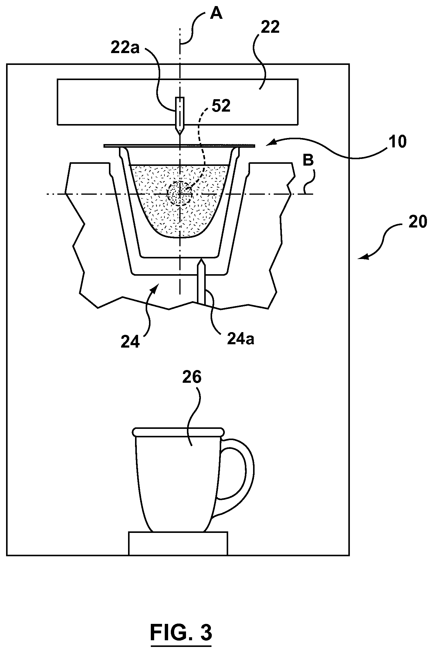
FIG. 3 is a schematic view of a capsule machine for use with a capsule in accordance with the present invention.
DESCRIPTION OF VARIOUS EMBODIMENTS
Various apparatuses or methods will be described below to provide examples of the claimed invention. The claimed invention is not limited to apparatuses or methods having all of the features of any one apparatus or method described below or to features common to multiple or all of the apparatuses described below. The claimed invention may reside in a combination or sub-combination of the apparatus elements or method steps described below. It is possible that an apparatus or method described below is not an example of the claimed invention. The applicant(s), inventor(s) and/or owner(s) reserve all rights in any invention disclosed in an apparatus or method described below that is not claimed in this document and do not abandon, disclaim or dedicate to the public any such invention by its disclosure in this document.
A capsule in accordance with the present invention is shown generally at 10 in the figures. Capsule 10 includes a body 12, filter 14 (when required), ingredients 16 and cover 18. Capsule may be sized to provide a single serving of a desired product or multiple servings.
Ingredients 16 include soluble and/or insoluble ingredients that are a precursor to forming a desired product. Preferably, ingredients 16 are provided in a dry state. Soluble ingredients may include instant coffee, chocolate, soup stock or other ingredients in powdered, crystallized or other forms adapted for solubility or contained within a soluble film or pouch. Insoluble ingredients may include tea leaves, coffee grounds, herbs or other ingredients adapted for forming a consumable product by extraction or infusion. Ingredients 16 may also include active ingredients (eg foaming agents), natural health additives, regulated drugs, alcohol or other soluble or insoluble ingredients.
Ingredients 16 may be disposed in a plurality of distinct regions R1, R2 . . . Rn within capsule 10. The same type of ingredients 16 may be disposed in each region R or different types of ingredients 16 may be disposed in different regions R. The density, cohesion or other physical properties of ingredients 16 may also vary between regions R.
Capsule 10 is sized and configured for use in a machine 20 that is adapted for preparing a product from capsule 10. Machine 20 may include an injection system 22 for injecting a fluid, typically heated water, into the capsule for mixing with ingredients 16. Injection system 22 may include a nozzle 22a disposed on machine 20 that is adapted to pierce cover 18 to inject fluid into capsule 10. Injection system 22 may alternatively have at least one component disposed on capsule 10, such as on cover 18, and adapted to pierce body 12 and interact with machine 20 to inject fluid into capsule 10.
Machine may also include a dispensing system 24 for dispensing product from capsule 10 into a desired receptacle 26 such as a bowl or cup. Dispensing system 24 may include a hollow probe 24a that is adapted to pierce capsule 10 to dispense a prepared product from capsule 10.
Body 12 of capsule 10 includes a sidewall 30 and an end wall 32 together defining an interior space 34. An opening 36 is defined at one end of body 12 and a flange 38 extends around the perimeter of opening 36 to receive cover 18 and to support capsule 10 within machine 20.
In another embodiment, body 12 may be formed with no end wall 32 and no sidewall 30 or a partial sidewall 30. Flange 38 may still extend around the perimeter of opening 36 to receive cover 18 and to support capsule 10 within machine 20. Filter 14 may be secured to flange 38 or to partial sidewall 30.
Filter 14 is adapted to be disposed within body 12 to define at least one ingredients chamber for receiving one or more ingredients 16 and in particular insoluble ingredients 16 that are not intended to be dispensed into receptacle 26 (for example coffee grounds or tea leaves).
Filter 14 is preferably adapted to be phobic to the fluid being injected into capsule 10. In most instances, the fluid will comprise water (either heated or cooled) and a hydrophobic filter 14 is desired. Filter 14 may be formed of materials that are phobic to fluid such as polyolefins (eg, polyethylene, polypropylene) and mixtures of polyolefins with other polymers or filter 14 may be coated with materials that are phobic to fluid such as a polyethylene coating.
Preferably, filter 14 is formed of a moldable non-woven filtration material that includes a plurality of multi-component fibers that are bound or interlocked by non-woven manufacturing techniques (such as spun bond techniques) to form a web having channels extending from one side of filter 14 to the other. The desired diameter for channels after forming is between 20 and 100 .mu.m, more preferably between 40 to 80 .mu.m. More details of a preferred filtration material for filter 14 are provided in US patent publication 20140127364 which is hereby incorporated in its entirety herein by reference.
Filter 14 may be secured to flange 38 or to an interior surface of capsule 10 (such as to sidewall 30). Capsule 10 may be provided without filter 14 in instances where ingredients are soluble or where it is desired that insoluble ingredients 16 are dispensed together with fluid into receptacle 26 (this requires that dispensing system be adapted to dispense insoluble ingredients 16).
Cover 18 is disposed over opening 36 and secured to body 12 such as by sealing cover 18 directly to flange 38 or indirectly with a portion of filter 14 located between.
A control member 50 may be defined by a cluster 52 of ingredients 16 disposed within capsule 10 as described further below. Control member 50 may comprise a first region R1 of ingredients 16 within capsule 10. The remainder of ingredients 16 for capsule 10 may comprise a second region R2 or capsule 10. Second region R2 may partially or fully surround first region R1. Ingredients 16 in second region R2 may be loosely disposed within capsule while ingredients in first region R1 are contained within cluster 52.
Control member 50 is disposed at a location 54 within capsule 10 that is adapted for controlling the flow of fluid injected into capsule 10. Such fluid control may comprise dispersing a flow of fluid for a period of time, absorbing a flow of fluid for a period of time or otherwise controlling or altering the flow of fluid within capsule 10. Control member 50 comprises a non-permanent structure that is adapted to at least partially dissolve or break apart within capsule when exposed to a flow of fluid over a set period of time (such as the period of time required to inject the desired amount of fluid into capsule 10).
Location 54 is selected according to the type of capsule machine 20 and injection system 22 for which capsule 10 is intended to be used as well as the type of ingredients 16 disposed within capsule 10. Location 54 for K-cup.TM. brewers for example may be along a central axis A of capsule 10 in line with the flow of fluid that is injected into capsule 10 through injection nozzle 22a. Location 54 may also be along a transverse axis B where cluster 52 is formed as a layer or crust. In some instances it may be desirable for location 54 to be at a lower portion of capsule 10 and in other instances in may be preferable for location 54 to be at an upper location of capsule.
Cluster 52 comprises a portion of ingredients 16 that are non permanently bound together on their own or with the addition of a binder material. Cluster 52 is adapted to at least partially break apart or dissolve over a desired dwell time T within capsule, when exposed to the flow of fluid in a desired manner from a desired injection system 22.
Cluster 52 may be formed by compressing a portion of ingredients 16 by a desired amount as depicted in FIG. 2(a). The compression can be achieved by a compacting device or an auger system with a relatively high taper which delivers a compacted power to a container. The compression may occur during the process of filling capsule with ingredients or it may occur at a prior stage to filling capsule. Cluster 52 of compressed ingredients is adapted to dissolve or break apart over a period of time when exposed to a flow of fluid within capsule. A cluster 52 of compressed ingredients 16 allows a greater amount of ingredients 16 to be disposed within the same space within capsule 10. Cluster 52 (or region R1) has a higher density of ingredients 16 than ingredients disposed outside of cluster 52 in region R2.
Alternatively, cluster 52 may be formed with a desired binder material 56 as depicted in FIG. 2(b). Binder material 56 is preferably in a liquid state. For example, binder material 56 may be a neutral binder material or it may be an active binder material. A neutral binder material does not add any noticeable flavor, odour, sensory, health benefit or function to the consumable product produced from capsule 10 but may combine or agglomerate with a portion of ingredients 16 to form cluster 52. Examples of neutral binder materials include polyethylene glycol, polypropylene glycol, ethyl alcohol etc. An active binder material provides flavor, odour, sensory, health benefit or function to the consumable product and also may combine or agglomerate with a portion of ingredients 16 to form cluster 52. Examples of an active binder material include Ethyl-2-methybutyrate (apple), 1-octen-3-ol, (mushroom), p-menthene-8-thiol (Grapefruit), 5-methyl-2-hepten-4-one (Hazelnut). The active binder is employed either directly at a high concentration or diluted with a neutral material. Both neutral and active binder materials are preferably highly water soluble.
Alternatively, cluster 52 may be formed with a soluble container 58 that is adapted to contain the portion of ingredients 16 as depicted in FIG. 2(c). For example, soluble container 58 may be formed of soluble gels or films, preferably with water-soluble film. The portion of ingredients 16 contained within soluble container 58 may include liquid ingredients (such as a concentrate) or other ingredients that must be kept separated within capsule (such as foaming agents or other active ingredients).
Preferred materials for soluble container 58 include protein or carbohydrate based materials which could be starch based (e.g., amylose film and amylopectin film), protein based (e.g., gelatin film, casein film), polysaccharide based (e.g., pullulan film, cellulose film), alginate sodium film and pectin film, to name a few. For example, the Vivos.TM. edible water soluble film from MonoSol can be employed as a soluble container 58 for ingredients 16. The dissolution rate of soluble container 58, and thus cluster 52, is dependent on the material type. Within the same type, the dissolution rate is normally slower when having heavier material density or molecular weight. Preferably the film thickness for soluble container 58 is in the range of 10-100 .mu.m, more preferably 20-80 .mu.m and most preferably 30-70 .mu.m.
Alternatively, cluster 52 may be provided as a tablet 60 as illustrated in FIG. 2(d). Tablet 60 may contain active or functional ingredients, which can be separated from the rest of ingredients. For instance, a food flavor in a tablet format can be used in this application to add certain flavor into food product.
Control member 50 is sized to control at least a portion of the flow of fluid injected into capsule 10 to other locations within the capsule. Preferably, for a single serve capsule, a single control member 50 has a width in the range of 1 to 25 millimeters and more preferably in the range of 5 to 15 millimeters. Multiple control members 50 comprising one or more types of clusters 52 may be disposed within capsule 10, in which case each control member 50 may have a smaller size.
While the above description provides examples of one or more processes or apparatuses, it will be appreciated that other processes or apparatuses may be within the scope of the accompanying claims.
* * * * *
D00000
D00001
D00002
XML
uspto.report is an independent third-party trademark research tool that is not affiliated, endorsed, or sponsored by the United States Patent and Trademark Office (USPTO) or any other governmental organization. The information provided by uspto.report is based on publicly available data at the time of writing and is intended for informational purposes only.
While we strive to provide accurate and up-to-date information, we do not guarantee the accuracy, completeness, reliability, or suitability of the information displayed on this site. The use of this site is at your own risk. Any reliance you place on such information is therefore strictly at your own risk.
All official trademark data, including owner information, should be verified by visiting the official USPTO website at www.uspto.gov. This site is not intended to replace professional legal advice and should not be used as a substitute for consulting with a legal professional who is knowledgeable about trademark law.