Methods and apparatus for delivering staples to a target tissue
Euteneuer , et al. Feb
U.S. patent number 10,568,622 [Application Number 14/733,458] was granted by the patent office on 2020-02-25 for methods and apparatus for delivering staples to a target tissue. This patent grant is currently assigned to Rotation Medical, Inc.. The grantee listed for this patent is Rotation Medical, Inc.. Invention is credited to Charles L. Euteneuer, Diane M. Feehan, Duane Frion, Rebecca McCarville, Nathaniel Zenz-Olson.


View All Diagrams
| United States Patent | 10,568,622 |
| Euteneuer , et al. | February 25, 2020 |
Methods and apparatus for delivering staples to a target tissue
Abstract
A device for attaching a sheet-like implant to a target tissue includes a pilot member and a staple push rod. In some embodiments, the pilot member has a distal end and at least a pair of prongs extending from the distal end. The prongs are configured to form pilot holes when the distal end of the pilot member is pressed against the target tissue. The staple push rod is disposed within at least a portion of the pilot member and slidable relative thereto. The staple push rod includes at least a pair of stakes. Each stake is dimensioned to engage a surface of a staple to apply pushing forces thereto. Each stake is positioned relative to a prong along an inner surface of the pilot member so that the stakes advance into the pilot holes when the stakes are moved in a distal direction. Methods for attaching a sheet-like implant to a target tissue are also disclosed.
| Inventors: | Euteneuer; Charles L. (St. Michael, MN), McCarville; Rebecca (Spring Park, MN), Frion; Duane (Brooklyn Center, MN), Zenz-Olson; Nathaniel (Blaine, MN), Feehan; Diane M. (Corcoran, MN) | ||||||||||
|---|---|---|---|---|---|---|---|---|---|---|---|
| Applicant: |
|
||||||||||
| Assignee: | Rotation Medical, Inc.
(Plymouth, MN) |
||||||||||
| Family ID: | 42370951 | ||||||||||
| Appl. No.: | 14/733,458 | ||||||||||
| Filed: | June 8, 2015 |
Prior Publication Data
| Document Identifier | Publication Date | |
|---|---|---|
| US 20150272573 A1 | Oct 1, 2015 | |
Related U.S. Patent Documents
| Application Number | Filing Date | Patent Number | Issue Date | ||
|---|---|---|---|---|---|
| 13889687 | May 8, 2013 | 9095337 | |||
| 12794551 | Sep 2, 2014 | 8821536 | |||
| 61313051 | Mar 11, 2010 | ||||
| 61253800 | Oct 21, 2009 | ||||
| 61184198 | Jun 4, 2009 | ||||
| Current U.S. Class: | 1/1 |
| Current CPC Class: | A61F 2/08 (20130101); A61F 2/30749 (20130101); A61B 17/068 (20130101); A61B 17/0682 (20130101); A61B 17/0644 (20130101); A61B 17/0642 (20130101); A61F 2/0063 (20130101); A61B 17/064 (20130101); A61B 2017/0046 (20130101); A61B 2017/00004 (20130101); A61F 2220/0016 (20130101); A61B 17/0643 (20130101); A61B 2017/0645 (20130101); A61B 17/0491 (20130101); A61B 2017/00862 (20130101) |
| Current International Class: | A61B 17/068 (20060101); A61F 2/30 (20060101); A61F 2/00 (20060101); A61F 2/08 (20060101); A61B 17/064 (20060101); A61B 17/04 (20060101); A61B 17/00 (20060101) |
References Cited [Referenced By]
U.S. Patent Documents
| 511238 | December 1893 | Hieatzman |
| 765793 | July 1904 | Ruckel |
| 1728316 | September 1929 | Von Wachenfeldt |
| 1855546 | April 1932 | File |
| 1868100 | July 1932 | Goodstein |
| 1910688 | May 1933 | Goodstein |
| 1940351 | December 1933 | Howard |
| 2034785 | March 1936 | Wappler |
| 2075508 | March 1937 | Davidson |
| 2131321 | September 1938 | Hart |
| 2158242 | May 1939 | Maynard |
| 2199025 | April 1940 | Conn |
| 2201610 | May 1940 | Dawson, Jr. |
| 2254620 | September 1941 | Miller |
| 2277931 | March 1942 | Moe |
| 2283814 | May 1942 | La Place |
| 2316297 | April 1943 | Southerland et al. |
| 2421193 | May 1947 | Gardner |
| 2571813 | October 1951 | Austin |
| 2630316 | March 1953 | Foster |
| 2684070 | July 1954 | Kelsey |
| 2744251 | May 1956 | Vollmer |
| 2790341 | April 1957 | Keep et al. |
| 2817339 | December 1957 | Sullivan |
| 2825162 | March 1958 | Flood |
| 2881762 | April 1959 | Lowrie |
| 2910067 | October 1959 | White |
| 3068870 | December 1962 | Levin |
| 3077812 | February 1963 | Dietrich |
| 3103666 | September 1963 | Bone |
| 3123077 | March 1964 | Alcamo |
| 3209754 | October 1965 | Brown |
| 3221746 | December 1965 | Noble |
| 3470834 | October 1969 | Bone |
| 3527223 | September 1970 | Shein |
| 3570497 | March 1971 | Lemole |
| 3577837 | May 1971 | Bader, Jr. |
| 3579831 | May 1971 | Stevens et al. |
| 3643851 | February 1972 | Green et al. |
| 3687138 | September 1972 | Jarvik |
| 3716058 | February 1973 | Tanner, Jr. |
| 3717294 | February 1973 | Green |
| 3757629 | September 1973 | Schneider |
| 3777538 | December 1973 | Weatherly et al. |
| 3837555 | September 1974 | Green |
| 3845772 | November 1974 | Smith |
| 3875648 | April 1975 | Bone |
| 3960147 | June 1976 | Murray |
| 3976079 | August 1976 | Samuels et al. |
| 4014492 | March 1977 | Rothfuss |
| 4127227 | November 1978 | Green |
| 4259959 | April 1981 | Walker |
| 4263903 | April 1981 | Griggs |
| 4265226 | May 1981 | Cassimally |
| 4317451 | March 1982 | Cerwin et al. |
| 4400833 | August 1983 | Kurland |
| 4422567 | December 1983 | Haynes |
| 4454875 | June 1984 | Pratt et al. |
| 4480641 | November 1984 | Failla et al. |
| 4485816 | December 1984 | Krumme |
| 4526174 | July 1985 | Froehlich |
| 4549545 | October 1985 | Levy |
| 4570623 | February 1986 | Ellison et al. |
| 4595007 | June 1986 | Mericle |
| 4624254 | November 1986 | McGarry et al. |
| 4627437 | December 1986 | Bedi et al. |
| 4632100 | December 1986 | Somers et al. |
| 4635637 | January 1987 | Schreiber |
| 4669473 | June 1987 | Richards et al. |
| 4696300 | September 1987 | Anderson |
| 4719917 | January 1988 | Barrows et al. |
| 4738255 | April 1988 | Goble et al. |
| 4741330 | May 1988 | Hayhurst |
| 4762260 | August 1988 | Richards et al. |
| 4799495 | January 1989 | Hawkins et al. |
| 4809695 | March 1989 | Gwathmey et al. |
| 4821721 | April 1989 | Chin |
| 4851005 | July 1989 | Hunt et al. |
| 4858608 | August 1989 | McQuilkin |
| 4884572 | December 1989 | Bays et al. |
| 4887601 | December 1989 | Richards |
| 4924866 | May 1990 | Yoon |
| 4930674 | June 1990 | Barak |
| 4968315 | November 1990 | Gatturna |
| 4976715 | December 1990 | Bays et al. |
| 4994073 | February 1991 | Green |
| 4997436 | March 1991 | Oberlander |
| 5002563 | March 1991 | Pyka et al. |
| 5013316 | May 1991 | Goble et al. |
| 5015249 | May 1991 | Nakao et al. |
| 5037422 | August 1991 | Hayhurst et al. |
| 5041129 | August 1991 | Hayhurst et al. |
| 5046513 | September 1991 | Gatturna et al. |
| 5053047 | October 1991 | Yoon |
| 5059206 | October 1991 | Winters |
| 5062563 | November 1991 | Green et al. |
| 5100417 | March 1992 | Cerier et al. |
| 5102421 | April 1992 | Anspach, Jr. |
| 5116357 | May 1992 | Eberbach |
| 5122155 | June 1992 | Eberbach |
| 5123913 | June 1992 | Wilk et al. |
| RE34021 | August 1992 | Mueller et al. |
| 5141515 | August 1992 | Eberbach |
| 5141520 | August 1992 | Goble et al. |
| 5156609 | October 1992 | Nakao et al. |
| 5156616 | October 1992 | Meadows et al. |
| 5167665 | December 1992 | McKinney |
| 5171259 | December 1992 | Inoue |
| 5174295 | December 1992 | Christian et al. |
| 5174487 | December 1992 | Rothfuss et al. |
| 5176682 | January 1993 | Chow |
| 5176692 | January 1993 | Wilk et al. |
| 5203787 | April 1993 | Noblitt et al. |
| 5217472 | June 1993 | Green et al. |
| 5222961 | June 1993 | Nakao |
| 5224946 | July 1993 | Hayhurst et al. |
| 5242457 | September 1993 | Akopov et al. |
| 5246441 | September 1993 | Ross et al. |
| 5251642 | October 1993 | Handlos |
| 5261914 | November 1993 | Warren |
| 5269753 | December 1993 | Wilk |
| 5269783 | December 1993 | Sander |
| 5282829 | February 1994 | Hermes |
| 5289963 | March 1994 | McGarry et al. |
| 5290217 | March 1994 | Campos |
| 5304187 | April 1994 | Green et al. |
| 5333624 | August 1994 | Tovey |
| 5342396 | August 1994 | Cook |
| 5350400 | September 1994 | Esposito et al. |
| 5352229 | October 1994 | Goble et al. |
| 5354292 | October 1994 | Braeuer et al. |
| 5364408 | November 1994 | Gordon |
| 5366460 | November 1994 | Eberbach |
| 5370650 | December 1994 | Tovey et al. |
| 5372604 | December 1994 | Trott |
| 5380334 | January 1995 | Torrie et al. |
| 5383477 | January 1995 | DeMatteis |
| 5397332 | March 1995 | Kammerer et al. |
| 5403326 | April 1995 | Harrison et al. |
| 5405360 | April 1995 | Tovey |
| 5411522 | May 1995 | Trott |
| 5411523 | May 1995 | Goble |
| 5417691 | May 1995 | Hayhurst |
| 5417712 | May 1995 | Whittaker et al. |
| 5425490 | June 1995 | Goble et al. |
| 5441502 | August 1995 | Bartlett |
| 5441508 | August 1995 | Gazielly et al. |
| 5456720 | October 1995 | Schultz et al. |
| 5464403 | November 1995 | Kieturakis et al. |
| 5478354 | December 1995 | Tovey et al. |
| 5486197 | January 1996 | Le et al. |
| 5497933 | March 1996 | DeFonzo et al. |
| 5500000 | March 1996 | Feagin et al. |
| 5501695 | March 1996 | Anspach, Jr. et al. |
| 5503623 | April 1996 | Tilton, Jr. |
| 5505735 | April 1996 | Li |
| 5507754 | April 1996 | Green et al. |
| 5520700 | May 1996 | Beyar et al. |
| 5522817 | June 1996 | Sander et al. |
| 5545180 | August 1996 | Le et al. |
| 5560532 | October 1996 | DeFonzo et al. |
| 5562689 | October 1996 | Green et al. |
| 5569306 | October 1996 | Thal et al. |
| 5582616 | December 1996 | Bolduc et al. |
| 5584835 | December 1996 | Greenfield |
| 5618314 | April 1997 | Harwin et al. |
| 5622257 | April 1997 | Deschenes et al. |
| 5628751 | May 1997 | Sander et al. |
| 5643319 | July 1997 | Green et al. |
| 5643321 | July 1997 | McDevitt |
| 5647874 | July 1997 | Hayhurst |
| 5649963 | July 1997 | McDevitt |
| 5662683 | September 1997 | Kay |
| 5667513 | September 1997 | Torrie et al. |
| 5674245 | October 1997 | Ilgen |
| 5681342 | October 1997 | Benchetrit |
| 5702215 | December 1997 | Li |
| 5713903 | February 1998 | Sander et al. |
| 5720753 | February 1998 | Sander et al. |
| 5725541 | March 1998 | Anspach, III et al. |
| 5741282 | April 1998 | Anspach, III et al. |
| 5766246 | June 1998 | Mulhauser et al. |
| 5782864 | July 1998 | Lizardi |
| 5797909 | August 1998 | Michelson |
| 5797931 | August 1998 | Bito et al. |
| 5797963 | August 1998 | McDevitt |
| 5807403 | September 1998 | Beyar et al. |
| 5830221 | November 1998 | Stein et al. |
| 5836961 | November 1998 | Kieturakis et al. |
| 5868762 | February 1999 | Cragg et al. |
| 5873891 | February 1999 | Sohn |
| 5885258 | March 1999 | Sachdeva et al. |
| 5885294 | March 1999 | Pedlick et al. |
| 5893856 | April 1999 | Jacob et al. |
| 5904696 | May 1999 | Rosenman |
| 5919184 | July 1999 | Tilton, Jr. |
| 5922026 | July 1999 | Chin |
| 5948000 | September 1999 | Larsen et al. |
| 5957939 | September 1999 | Heaven et al. |
| 5957953 | September 1999 | Dipoto et al. |
| 5968044 | October 1999 | Nicholson et al. |
| 5980557 | November 1999 | Iserin et al. |
| 5988171 | November 1999 | Sohn |
| 5989265 | November 1999 | Bouquet De La Joliniere et al. |
| 5997552 | December 1999 | Person et al. |
| 6063088 | May 2000 | Winslow |
| 6156045 | December 2000 | Ulbrich et al. |
| 6179840 | January 2001 | Bowman |
| 6193731 | February 2001 | Oppelt et al. |
| 6193733 | February 2001 | Adams |
| 6245072 | June 2001 | Zdeblick et al. |
| 6302885 | October 2001 | Essiger |
| 6312442 | November 2001 | Kieturakis et al. |
| 6315789 | November 2001 | Cragg |
| 6318616 | November 2001 | Pasqualucci et al. |
| 6322563 | November 2001 | Cummings et al. |
| 6325805 | December 2001 | Ogilvie et al. |
| 6387113 | May 2002 | Hawkins et al. |
| 6391333 | May 2002 | Li et al. |
| 6413274 | July 2002 | Pedros |
| 6425900 | July 2002 | Knodel et al. |
| 6436110 | August 2002 | Bowman et al. |
| 6447522 | September 2002 | Gambale et al. |
| 6447524 | September 2002 | Knodel et al. |
| 6478803 | November 2002 | Kapec et al. |
| 6482178 | November 2002 | Andrews et al. |
| 6482210 | November 2002 | Skiba et al. |
| 6506190 | January 2003 | Walshe |
| 6511499 | January 2003 | Schmieding et al. |
| 6517564 | February 2003 | Grafton et al. |
| 6524316 | February 2003 | Nicholson et al. |
| 6527795 | March 2003 | Lizardi |
| 6530933 | March 2003 | Yeung et al. |
| 6540769 | April 2003 | Miller, III |
| 6551333 | April 2003 | Kuhns et al. |
| 6554852 | April 2003 | Oberlander |
| 6569186 | May 2003 | Winters et al. |
| 6575976 | June 2003 | Grafton |
| 6599289 | July 2003 | Bojarski et al. |
| 6620185 | September 2003 | Harvie et al. |
| 6629988 | October 2003 | Weadock |
| 6638297 | October 2003 | Huitema |
| 6648893 | November 2003 | Dudasik |
| 6666872 | December 2003 | Barreiro et al. |
| 6673094 | January 2004 | McDevitt et al. |
| 6685728 | February 2004 | Sinnott et al. |
| 6692506 | February 2004 | Ory et al. |
| 6723099 | April 2004 | Goshert |
| 6726704 | April 2004 | Loshakove et al. |
| 6726705 | April 2004 | Peterson et al. |
| 6740100 | May 2004 | Demopulos et al. |
| 6746472 | June 2004 | Frazier et al. |
| 6764500 | July 2004 | Muijs Van De Moer et al. |
| 6770073 | August 2004 | McDevitt et al. |
| 6779701 | August 2004 | Bailly et al. |
| 6800081 | October 2004 | Parodi |
| 6835206 | December 2004 | Jackson |
| 6849078 | February 2005 | Durgin et al. |
| 6887259 | May 2005 | Lizardi |
| 6926723 | August 2005 | Mulhauser et al. |
| 6932834 | August 2005 | Lizardi et al. |
| 6939365 | September 2005 | Fogarty et al. |
| 6946003 | September 2005 | Wolowacz et al. |
| 6949117 | September 2005 | Gambale et al. |
| 6964685 | November 2005 | Murray et al. |
| 6966916 | November 2005 | Kumar |
| 6972027 | December 2005 | Fallin et al. |
| 6984241 | January 2006 | Lubbers et al. |
| 6991597 | January 2006 | Gellman et al. |
| 7008435 | March 2006 | Cummins |
| 7021316 | April 2006 | Leiboff |
| 7025772 | April 2006 | Gellman et al. |
| 7033379 | April 2006 | Peterson |
| 7037324 | May 2006 | Martinek |
| 7048171 | May 2006 | Thornton et al. |
| 7063711 | June 2006 | Loshakove et al. |
| 7083638 | August 2006 | Foerster |
| 7087064 | August 2006 | Hyde |
| 7112214 | September 2006 | Peterson et al. |
| 7118581 | October 2006 | Friden |
| 7144413 | December 2006 | Wilford et al. |
| 7144414 | December 2006 | Harvie et al. |
| 7150750 | December 2006 | Damarati |
| 7153314 | December 2006 | Laufer et al. |
| 7160314 | January 2007 | Sgro et al. |
| 7160326 | January 2007 | Ball |
| 7163551 | January 2007 | Anthony et al. |
| 7163563 | January 2007 | Schwartz et al. |
| 7169157 | January 2007 | Kayan |
| 7189251 | March 2007 | Kay |
| 7201754 | April 2007 | Stewart et al. |
| 7214232 | May 2007 | Bowman et al. |
| 7226469 | June 2007 | Benavitz et al. |
| 7229452 | June 2007 | Kayan |
| 7247164 | July 2007 | Ritchart et al. |
| 7303577 | December 2007 | Dean |
| 7309337 | December 2007 | Colleran et al. |
| 7320692 | January 2008 | Bender et al. |
| 7320701 | January 2008 | Haut et al. |
| 7322935 | January 2008 | Palmer et al. |
| 7326231 | February 2008 | Phillips et al. |
| 7343920 | March 2008 | Toby et al. |
| 7368124 | May 2008 | Chun et al. |
| 7377934 | May 2008 | Lin et al. |
| 7381213 | June 2008 | Lizardi |
| 7390329 | June 2008 | Westra et al. |
| 7399304 | July 2008 | Gambale et al. |
| 7404824 | July 2008 | Webler et al. |
| 7416554 | August 2008 | Lam et al. |
| 7452368 | November 2008 | Liberatore et al. |
| 7460913 | December 2008 | Kuzma et al. |
| 7463933 | December 2008 | Wahlstrom et al. |
| 7465308 | December 2008 | Sikora et al. |
| 7481832 | January 2009 | Meridew et al. |
| 7485124 | February 2009 | Kuhns et al. |
| 7497854 | March 2009 | Gill et al. |
| 7500972 | March 2009 | Voegele et al. |
| 7500980 | March 2009 | Gill et al. |
| 7500983 | March 2009 | Kaiser et al. |
| 7503474 | March 2009 | Hillstead et al. |
| 7506791 | March 2009 | Omaits et al. |
| 7559941 | July 2009 | Zannis et al. |
| 7572276 | August 2009 | Lim et al. |
| 7585311 | September 2009 | Green et al. |
| 7766208 | August 2010 | Epperly et al. |
| 7771440 | August 2010 | Ortiz et al. |
| 7776057 | August 2010 | Laufer et al. |
| 7780685 | August 2010 | Hunt et al. |
| 7785255 | August 2010 | Malkani |
| 7807192 | October 2010 | Li et al. |
| 7819880 | October 2010 | Zannis et al. |
| 7918879 | April 2011 | Yeung et al. |
| 8114101 | February 2012 | Criscuolo et al. |
| 8197837 | June 2012 | Jamiolkowski et al. |
| 8821536 | September 2014 | Euteneuer et al. |
| 2002/0077687 | June 2002 | Ahn |
| 2002/0090725 | July 2002 | Simpson et al. |
| 2002/0123767 | September 2002 | Prestel |
| 2002/0165559 | November 2002 | Grant et al. |
| 2003/0073979 | April 2003 | Naimark et al. |
| 2003/0125748 | July 2003 | Li et al. |
| 2003/0212456 | November 2003 | Lipchitz et al. |
| 2004/0059416 | March 2004 | Murray et al. |
| 2004/0138705 | July 2004 | Heino et al. |
| 2004/0167519 | August 2004 | Weiner et al. |
| 2005/0015021 | January 2005 | Shiber |
| 2005/0049618 | March 2005 | Masuda et al. |
| 2005/0051597 | March 2005 | Toledano |
| 2005/0059996 | March 2005 | Bauman et al. |
| 2005/0060033 | March 2005 | Vacanti et al. |
| 2005/0107807 | May 2005 | Nakao |
| 2005/0113736 | May 2005 | Orr et al. |
| 2005/0171569 | August 2005 | Girard et al. |
| 2005/0187576 | August 2005 | Whitman et al. |
| 2005/0240222 | October 2005 | Shipp |
| 2005/0274768 | December 2005 | Cummins et al. |
| 2006/0074423 | April 2006 | Alleyne et al. |
| 2006/0178743 | August 2006 | Carter |
| 2006/0235442 | October 2006 | Huitema |
| 2006/0293760 | December 2006 | Dedeyne |
| 2007/0078477 | April 2007 | Heneveld, Sr. et al. |
| 2007/0083236 | April 2007 | Sikora et al. |
| 2007/0112361 | May 2007 | Schonholz et al. |
| 2007/0179531 | August 2007 | Thornes |
| 2007/0185506 | August 2007 | Jackson |
| 2007/0190108 | August 2007 | Datta et al. |
| 2007/0219558 | September 2007 | Deutsch |
| 2007/0270804 | November 2007 | Chudik |
| 2007/0288023 | December 2007 | Pellegrino et al. |
| 2008/0027470 | January 2008 | Hart et al. |
| 2008/0051888 | February 2008 | Ratcliffe et al. |
| 2008/0065153 | March 2008 | Allard et al. |
| 2008/0090936 | April 2008 | Fujimura et al. |
| 2008/0125869 | May 2008 | Paz et al. |
| 2008/0135600 | June 2008 | Hiranuma et al. |
| 2008/0173691 | July 2008 | Mas et al. |
| 2008/0188874 | August 2008 | Henderson |
| 2008/0188936 | August 2008 | Ball et al. |
| 2008/0195119 | August 2008 | Ferree |
| 2008/0200949 | August 2008 | Hiles et al. |
| 2008/0241213 | October 2008 | Chun et al. |
| 2008/0272173 | November 2008 | Coleman et al. |
| 2008/0306408 | December 2008 | Lo |
| 2009/0001122 | January 2009 | Prommersberger et al. |
| 2009/0012521 | January 2009 | Axelson, Jr. et al. |
| 2009/0030434 | January 2009 | Paz et al. |
| 2009/0069806 | March 2009 | De La Mora Levy et al. |
| 2009/0076541 | March 2009 | Chin et al. |
| 2009/0105535 | April 2009 | Green et al. |
| 2009/0112085 | April 2009 | Eby |
| 2009/0134198 | May 2009 | Knodel et al. |
| 2009/0156986 | June 2009 | Trenhaile |
| 2009/0156997 | June 2009 | Trenhaile |
| 2009/0182245 | July 2009 | Zambelli |
| 2009/0242609 | October 2009 | Kanner |
| 2010/0145367 | June 2010 | Ratcliffe |
| 2010/0147922 | June 2010 | Olson |
| 2010/0163598 | July 2010 | Belzer |
| 2010/0191332 | July 2010 | Euteneuer et al. |
| 2010/0241227 | September 2010 | Euteneuer et al. |
| 2010/0249801 | September 2010 | Sengun et al. |
| 2010/0256675 | October 2010 | Romans |
| 2010/0274278 | October 2010 | Fleenor et al. |
| 2010/0292715 | November 2010 | Nering et al. |
| 2010/0292791 | November 2010 | Lu et al. |
| 2010/0312250 | December 2010 | Euteneuer et al. |
| 2010/0312275 | December 2010 | Euteneuer et al. |
| 2010/0327042 | December 2010 | Amid et al. |
| 2011/0000950 | January 2011 | Euteneuer et al. |
| 2011/0004221 | January 2011 | Euteneuer et al. |
| 2011/0011917 | January 2011 | Loulmet |
| 2011/0034942 | February 2011 | Levin et al. |
| 2011/0040310 | February 2011 | Levin et al. |
| 2011/0040311 | February 2011 | Levin et al. |
| 2011/0066166 | March 2011 | Levin et al. |
| 2011/0106154 | May 2011 | DiMatteo et al. |
| 2011/0114700 | May 2011 | Baxter, III et al. |
| 2011/0224702 | September 2011 | Van Kampen et al. |
| 2011/0264149 | October 2011 | Pappalardo et al. |
| 2012/0160893 | June 2012 | Harris et al. |
| 2012/0193391 | August 2012 | Michler et al. |
| 2012/0209401 | August 2012 | Euteneuer et al. |
| 2012/0211543 | August 2012 | Euteneuer |
| 2012/0248171 | October 2012 | Bailly et al. |
| 2012/0316608 | December 2012 | Foley |
| 2013/0153627 | June 2013 | Euteneuer et al. |
| 2013/0153628 | June 2013 | Euteneuer |
| 2013/0158554 | June 2013 | Euteneuer et al. |
| 2013/0158587 | June 2013 | Euteneuer et al. |
| 2013/0158661 | June 2013 | Euteneuer et al. |
| 2013/0172920 | July 2013 | Euteneuer et al. |
| 2013/0172997 | July 2013 | Euteneuer et al. |
| 2013/0184716 | July 2013 | Euteneuer et al. |
| 2013/0240598 | September 2013 | Euteneuer et al. |
| 2013/0245627 | September 2013 | Euteneuer et al. |
| 2013/0245682 | September 2013 | Euteneuer et al. |
| 2013/0245706 | September 2013 | Euteneuer et al. |
| 2013/0245707 | September 2013 | Euteneuer et al. |
| 2013/0245762 | September 2013 | Van Kampen et al. |
| 2013/0245774 | September 2013 | Euteneuer et al. |
| 2390508 | May 2001 | CA | |||
| 0142225 | May 1985 | EP | |||
| 0298400 | Jan 1989 | EP | |||
| 0390613 | Oct 1990 | EP | |||
| 0543499 | May 1993 | EP | |||
| 0548998 | Jun 1993 | EP | |||
| 0557963 | Sep 1993 | EP | |||
| 0589306 | Mar 1994 | EP | |||
| 0908152 | Apr 1999 | EP | |||
| 1491157 | Dec 2004 | EP | |||
| 1559379 | Aug 2005 | EP | |||
| 2030576 | Mar 2009 | EP | |||
| 2154688 | Sep 1985 | GB | |||
| 2397240 | Jul 2004 | GB | |||
| 58188442 | Nov 1983 | JP | |||
| 2005506122 | Mar 2005 | JP | |||
| 2006515774 | Jun 2006 | JP | |||
| 8505025 | Nov 1985 | WO | |||
| 0176456 | Oct 2001 | WO | |||
| 0234140 | May 2002 | WO | |||
| 03105670 | Dec 2003 | WO | |||
| 2004000138 | Dec 2003 | WO | |||
| 2004093690 | Nov 2004 | WO | |||
| 2005016389 | Feb 2005 | WO | |||
| 2006086679 | Aug 2006 | WO | |||
| 2007014910 | Feb 2007 | WO | |||
| 2007030676 | Mar 2007 | WO | |||
| 2007078978 | Jul 2007 | WO | |||
| 2007082088 | Jul 2007 | WO | |||
| 2008111073 | Sep 2008 | WO | |||
| 2008111078 | Sep 2008 | WO | |||
| 2008139473 | Nov 2008 | WO | |||
| 2009079211 | Jun 2009 | WO | |||
| 2009143331 | Nov 2009 | WO | |||
| 2011095890 | Aug 2011 | WO | |||
| 2011128903 | Oct 2011 | WO | |||
Other References
|
Bahler et al.; Trabecular Bypass Stents Decrease Intraocular Pressure in Cultured Human Anterior Segments; Am. J. Opthalmology; 138(6): 988-994; Dec. 2004. cited by applicant . Chamay et al.; Digital Contracture Deformity After Implantation of a Silicone Prosthesis: Light and Electron Microscopic Study; The Journal of Hand Surgery; 3(3): 266-270; May 1978. cited by applicant . D'Ermo et al.; Our Results with the Operation of ab externo; Ophthalmologica; 168: 347-355; 1971. cited by applicant . France et al.; Biomechanical Evaluation of Rotator Cuff Fixation Methods; The American Journal of Sports Medicine; 17(2): 176-181; Mar-Apr. 1989. cited by applicant . Goodship et al.; An Assessment of Filamentous Carbon Fibre for the Treatment of Tendon Injury in the Horse; Veterinary Record; 106: 217-221; Mar. 8, 1980. cited by applicant . Hunter et al.; Flexor-Tendon Reconstruction in Severely Damaged Hands; The Journal of Bone and Joint Surgery (American Volume); 53-A(5): 329-358; Jul. 1971. cited by applicant . Johnstone et al.; Microsurgery of Schlemm's Canal and the Human Aqueous Outflow System; Am. J. Opthalmology; 76(6): 906-917; Dec. 1973. cited by applicant . Kowalsky et al.; Evaluation of Suture Abrasion Against Rotator Cuff Tendon and Proximal Humerus Bone; Arthroscopy: The Journal of Arthroscopic and Related Surgery; 24(3): 329-334; Mar. 2008. cited by applicant . Lee et al.; Aqueous-Venous and Intraocular Pressure; Preliminary Report of Animal Studies; Investigative Ophthalmology; 5(1):59-64; Feb. 1966. cited by applicant . Maepea et al.; The Pressures in the Episcleral Veins, Schlemm's Canal and the Trabecular Meshwork in Monkeys: Effects of Changes in Intraocular Pressure; Exp. Eye Res.; 49: 645-663; Oct. 1989. cited by applicant . Nicolle et al.; A Silastic Tendon Prosthesis as an Adjunct to Flexor Tendon Grafting: An Experimental and Clinical Evaluation; British Journal of Plastic Surgery; 22(3-4): 224-236; 1969. cited by applicant . Rubin et al.; The Use of Acellular Biologic Tissue Patches in Foot and Ankle Surgery; Clinics in Podiatric Medicine and Surgery; 22: 533-552; Oct. 2005. cited by applicant . Schultz; Canaloplasty Procedure Shows Promise for Open-Angle Glaucoma in European Study; Ocular Surgery News; pp. 34-35; Mar. 1, 2007. cited by applicant . Spiegel et al.; Schlemm's Canal Implant: A New Method to Lower Intraocular Pressure in Patients with POAG; Ophthalmic Surgery and Lasers; 30(6): 492-494; Jun. 1999. cited by applicant . Stetson et al.; Arthroscopic Treatment of Partial Rotator Cuff Tears; Operative Techniques in Sports Medicine; 12 (2): 135-148; Apr. 2004. cited by applicant . Valdez et al.; Repair of Digital Flexor Tendon Lacerations in the Horse, Using Carbon Fiber Implants; JAYMA; 177 (5): 427-435; Sep. 1, 1980. cited by applicant . Wikipedia, The Free Encyclopedia; Rotator Cuff Tear; Downloaded from: <http://en.wikipedia.org/Rotator_cuff_tear> on Dec. 6, 2012; 14 pages. cited by applicant . Alexander et al.; Ligament and Tendon Repair with an Absorbable Polymer-Coated Carbon Fiber Stent; Bulletin of the Hospital for Joint Diseases Orthopaedic Institute; 46(2): 155-173; Fall 1986. cited by applicant. |
Primary Examiner: McEvoy; Thomas M
Attorney, Agent or Firm: Seager, Tufte & Wickhelm LLP
Parent Case Text
CROSS REFERENCE TO RELATED APPLICATIONS
This application is a continuation of U.S. application Ser. No. 13/889,687, filed May 8, 2013, which is a continuation of U.S. application Ser. No. 12/794,551, filed Jun. 4, 2010, which claims the benefit of U.S. provisional application Ser. No. 61/313,051 filed Mar. 11, 2010; U.S. provisional application Ser. No. 61/253,800, filed Oct. 21, 2009; and U.S. provisional application Ser. No. 61/184,198, filed Jun. 4, 2009, the disclosures of each incorporated herein by reference.
Claims
What is claimed is:
1. A device for attaching a sheet-like implant to a target tissue, comprising: a sheath having a proximal end, a distal end, and a pair of pilot-hole forming members extending distally therefrom; and a single staple push rod slidably disposed within the sheath and having fixed at a distal end thereof a pair of stakes, the pair of stakes having opposing laterally outward surfaces, the pair of stakes configured and adapted to directly and releasably engage a staple disposed at least partially within the sheath such that a portion of the staple is positioned between the laterally outward surfaces of the pair of stakes and an interior surface of the sheath, the single staple push rod being sized and adapted to impart a distally directed force to a staple disposed at least partially within the sheath such that the staple moves distally relative to the sheath distally beyond the pair of pilot-hole forming members, wherein the pair of pilot-hole forming members form pilot-holes when pressed against the target tissue, wherein the pair of stakes is positioned relative to the pair of pilot-hole forming members so that the pair of stakes advances distally into the pair of pilot-holes formed by the pair of pilot-hole forming members while the pair of pilot-hole forming members is in the pilot-holes when the pair of stakes is advanced distally relative to the sheath to extend distally beyond the distal ends of the pair of pilot-hole forming members.
2. The device of claim 1, wherein the pair of stakes diverge from one another to expand against an inner wall of the sheath.
3. The device of claim 1, further comprising a staple engaged with the pair of stakes, the staple comprising a first arm with a first passage extending at least partially through the first arm, a second arm with a second passage extending at least partially through the second arm, and a bridge connecting the first arm and the second arm.
4. The device of claim 3, wherein each stake is dimensioned such that at least a portion of each stake extends into one of the first passage or of the second passage of the staple when the staple is engaged with the pair of stakes.
5. The device of claim 3, wherein the pair of stakes apply a pushing force to the staple when the single staple push rod is advanced distally relative to the sheath, and wherein the pair of stakes impart a laterally outward component to the pushing force.
6. The device of claim 3, wherein the first passage extends from a proximal surface on the first arm to a distal surface on the first arm, wherein the second passage extends from a proximal surface on the second arm to a distal surface on the second arm, wherein each stake of the pair of stakes has a distal portion configured to extend into one of the first passage or of the second passage of the staple and to have a proximal portion wider than the distal portion, and wherein the proximal portion of each stake of the pair of stakes imparts a pushing force on the proximal surface of one of the first and second arms of the staple when the single staple push rod is advanced distally with respect to the sheath.
7. The device of claim 3, wherein each passage of each arm has a proximal opening and a distal opening, and wherein each stake extends through one of the first passage of the first arm or the second passage of the second arm and distally of the respective distal opening.
8. The device of claim 3, wherein each arm of the staple comprises a trunk portion and a fluke portion, wherein the fluke portion is offset from the trunk portion, and wherein the first passage and the second passage extend at least partially through the fluke portion of each arm.
9. The device of claim 8, wherein the pair of pilot-hole forming members have greater lengths than the fluke portion of each arm.
10. The device of claim 8, wherein the pair of stakes are configured to apply pushing forces to the staple offset from the trunk portion of each arm when the single staple push rod is advanced distally with respect to the sheath.
11. An apparatus for attaching a sheet-like implant to a target tissue, comprising: a tube member having a proximal end and a distal end, the distal end of the tube member forming a pair of distally extending pilot-hole forming prongs; a single staple push rod having a proximal end and a distal end and disposed at least partially within the tube member, the single staple push rod slidable relative to the tube member, wherein the distal end of the single staple push rod comprises a pair of stakes; and a staple engaged with the pair of stakes, the staple comprising a first arm with a first passage extending at least partially through the first arm, a second arm with a second passage extending at least partially through the second arm, and a bridge connecting the first arm and the second arm, wherein the pair of stakes is configured and adapted to directly and releasably engage the staple, wherein the pair of stakes is configured and adapted to impart a distally directed force on the staple such that the staple moves distally relative to the tube member distally beyond the pair of distally extending pilot-hole forming prongs, and wherein the pair of stakes is positioned relative to the pair of distally extending pilot-hole forming prongs so that the pair of stakes advance distally into pilot-holes formed by the pair of distally extending pilot-hole forming prongs while the pair of distally extending pilot-hole forming prongs is in the pilot-holes when the pair of stakes is advanced distally relative to the tube member to extend distally beyond the distal ends of the pair of pilot-hole forming members.
12. The apparatus of claim 11, wherein the pair of stakes apply a pushing force including a laterally outward component to the staple when the single staple push rod is advanced distally with respect to the tube member.
13. The apparatus of claim 11, wherein the pair of stakes apply a pushing force to a proximally facing surface of the first arm and to a proximally facing surface of the second arm.
14. The apparatus of claim 11, wherein the first arm comprises a first trunk portion and a first fluke portion offset from the first trunk portion and the second arm comprises a second trunk portion and a second fluke portion offset from the second trunk portion, wherein the first passage extends at least partially through the first fluke portion in a first direction with respect to a longitudinal axis of the first trunk portion, wherein the second passage extends at least partially through the second fluke portion in a second direction with respect to a longitudinal axis of the second trunk portion, wherein the first trunk portion and the second trunk portion are configured to bend under reaction forces when placed in tissue causing the first fluke portion and the second fluke portion to rotate such that the first passage extends at least partially through the first fluke portion in a third direction with respect to the longitudinal axis of the first trunk portion and the second passage extends at least partially through the second fluke portion in a fourth direction with respect to the longitudinal axis of the second trunk portion, wherein the first direction is different from the third direction and the second direction is different from the fourth direction.
15. The apparatus of claim 14, wherein the first trunk portion and the second trunk portion are configured to bend under reaction forces when placed in tissue causing the first fluke portion and the second fluke portion to rotate in opposite directions.
16. An apparatus for attaching a sheet-like implant to a target tissue, comprising: a sheath having a proximal end, a distal end, and a pair of distally extending pilot-hole forming prongs extending distally therefrom; a single staple push rod having a proximal end and a distal end and disposed at least partially within the sheath, the single staple push rod slidable relative to the sheath, wherein the distal end of the single staple push rod comprises a pair of stakes; and a staple disposed on the pair of stakes of the single staple push rod, the staple comprising a first arm with a first passage extending at least partially through the first arm, a second arm with a second passage extending at least partially through the second arm, and a bridge connecting the first arm and the second arm, wherein each stake of the pair of stakes includes a shoulder to directly push against and releasably engage the staple, wherein the shoulder of each stake of the pair of stakes is configured and adapted to impart a distally directed force on the staple such that the staple moves distally relative to the sheath distally beyond the pair of distally extending pilot-hole forming prongs, wherein a portion of the first arm extends distally beyond a distal opening of the first passage, and wherein a portion of the second arm extends distally beyond a distal opening of the second passage, and wherein the pair of distally extending pilot-hole forming prongs is in pilot-holes formed thereby when the pair of stakes is advanced distally relative to the sheath to extend distally beyond the distal ends of the pair of pilot-hole forming members.
17. The apparatus of claim 16, wherein the pair of stakes diverge from one another.
18. The apparatus of claim 16, wherein the first arm comprises a first trunk portion and a first fluke portion offset from the first trunk portion and the second arm comprises a second trunk portion and a second fluke portion offset from the second trunk portion, and wherein the first passage extends at least partially through the first fluke portion and the second passage extends at least partially through the second fluke portion.
19. The apparatus of claim 16, wherein the pair of stakes are positioned relative to the pair of distally extending pilot-hole forming prongs so that the pair of stakes advance into pilot-holes formed by the pair of distally extending pilot-hole forming prongs while the pair of distally extending pilot-hole forming prongs is in the pilot-holes when the pair of stakes are advanced distally relative to the sheath.
Description
INCORPORATION BY REFERENCE
All publications and patent applications mentioned in this specification are herein incorporated by reference to the same extent as if each individual publication or patent application was specifically and individually indicated to be incorporated by reference.
FIELD OF THE INVENTION
The present invention relates generally to orthopedic medicine and surgery. More particularly, the present invention relates to methods and apparatus for delivery and fixation of sheet-like materials, such as for treating articulating joints.
BACKGROUND OF THE INVENTION
The glenohumeral joint of the shoulder is found where the head of the humerus mates with a shallow depression in the scapula. This shallow depression is known as the glenoid fossa. Six muscles extend between the humerus and scapula and actuate the glenohumeral joint. These six muscles include the deltoid, the teres major, and the four rotator cuff muscles. As disclosed by Ball et al. in U.S. Patent Publication No. US 2008/0188936 A1 and as illustrated in FIG. 1 the rotator cuff muscles are a complex of four muscles. These four muscles are the supraspinatus, the infraspinatus, the subscapularis, and the teres minor. The centering and stabilizing roles played by the rotator cuff muscles are critical to the proper function of the shoulder. The rotator cuff muscles provide a wide variety of moments to rotate the humerus and to oppose unwanted components of the deltoid and pectoralis muscle forces.
The four muscles of the rotator cuff arise from the scapula 12. The distal tendons of the rotator cuff muscles splay out and interdigitate to form a common continuous insertion on the humerus 14. The subscapularis 16 arises from the anterior aspect of the scapula 12 and attaches over much of the lesser tuberosity of the humerous. The supraspinatus muscle 18 arises from the supraspinatus fossa of the posterior scapula, passes beneath the acromion and the acromioclavicular joint, and attaches to the superior aspect of the greater tuberosity 11. The infraspinatus muscle 13 arises from the infraspinous fossa of the posterior scapula and attaches to the posterolateral aspect of the greater tuberosity 11. The teres minor 15 arises from the lower lateral aspect of the scapula 12 and attaches to the lower aspect of the greater tuberosity 11.
The mechanics of the rotator cuff muscles 10 are complex. The rotator cuff muscles 10 rotate the humerus 14 with respect to the scapula 12, compress the humeral head 17 into the glenoid fossa providing a critical stabilizing mechanism to the shoulder (known as concavity compression), and provide muscular balance. The supraspinatus and infraspinatus provide 45 percent of abduction and 90 percent of external rotation strength. The supraspinatus and deltoid muscles are equally responsible for producing torque about the shoulder joint in the functional planes of motion.
The rotator cuff muscles 10 are critical elements of this shoulder muscle balance equation. The human shoulder has no fixed axis. In a specified position, activation of a muscle creates a unique set of rotational moments. For example, the anterior deltoid can exert moments in forward elevation, internal rotation, and cross-body movement. If forward elevation is to occur without rotation, the cross-body and internal rotation moments of this muscle must be neutralized by other muscles, such as the posterior deltoid and infraspinatus. The timing and magnitude of these balancing muscle effects must be precisely coordinated to avoid unwanted directions of humeral motion. Thus the simplified view of muscles as isolated motors, or as members of force couples must give way to an understanding that all shoulder muscles function together in a precisely coordinated way--opposing muscles canceling out undesired elements leaving only the net torque necessary to produce the desired action. Injury to any of these soft tissues can greatly inhibit ranges and types of motion of the arm.
With its complexity, range of motion and extensive use, a fairly common soft tissue injury is damage to the rotator cuff or rotator cuff tendons. Damage to the rotator cuff is a potentially serious medical condition that may occur during hyperextension, from an acute traumatic tear or from overuse of the joint. With its critical role in abduction, rotational strength and torque production, the most common injury associated with the rotator cuff region is a strain or tear involving the supraspinatus tendon. A tear in the supraspinitus tendon 19 is schematically depicted in FIG. 2. A tear at the insertion site of the tendon with the humerus, may result in the detachment of the tendon from the bone. This detachment may be partial or full, depending upon the severity of the injury. Additionally, the strain or tear can occur within the tendon itself. Injuries to the supraspinatus tendon 19 and recognized modalities for treatment are defined by the type and degree of tear. The first type of tear is a full thickness tear as also depicted in FIG. 2, which as the term indicates is a tear that extends through the thickness of the supraspinatus tendon regardless of whether it is completely torn laterally. The second type of tear is a partial thickness tear which is further classified based on how much of the thickness is torn, whether it is greater or less than 50% of the thickness.
The accepted treatment for a full thickness tear or a partial thickness tear greater than 50% includes reconnecting the torn tendon via sutures. For the partial thickness tears greater than 50%, the tear is completed to a full thickness tear by cutting the tendon prior to reconnection. In contrast to the treatment of a full thickness tear or a partial thickness tear of greater than 50%, the treatment for a partial thickness tear less than 50% usually involves physical cessation from use of the tendon, i.e., rest. Specific exercises can also be prescribed to strengthen and loosen the shoulder area. In many instances, the shoulder does not heal and the partial thickness tear can be the source of chronic pain and stiffness. Further, the pain and stiffness may cause restricted use of the limb which tends to result in further degeneration or atrophy in the shoulder. Surgical intervention may be required for a partial thickness tear of less than 50%, however, current treatment interventions do not include repair of the tendon, rather the surgical procedure is directed to arthroscopic removal of bone to relieve points of impingement or create a larger tunnel between the tendon and bone that is believed to be causing tendon damage. As part of the treatment, degenerated tendon may also be removed using a debridement procedure in which tendon material is ablated. Again, the tendon partial tear is not repaired. Several authors have reported satisfactory early post operative results from these procedures, but over time recurrent symptoms have been noted. In the event of recurrent symptoms, many times a patient will "live with the pain". This may result in less use of the aim and shoulder which further causes degeneration of the tendon and may lead to more extensive damage. A tendon repair would then need to be done in a later procedure if the prescribed treatment for partial tear was unsuccessful in relieving pain and stiffness or over time the tear propagated through injury or degeneration to a full thickness tear or a partial thickness tear greater than 50% with attendant pain and debilitation. A subsequent later procedure would include the more drastic procedure of completing the tear to full thickness and suturing the ends of the tendon back together. This procedure requires extensive rehabilitation, has relatively high failure rates and subjects the patient who first presented and was treated with a partial thickness tear less than 50% to a second surgical procedure.
As described above, adequate treatments do not currently exist for repairing a partial thickness tear of less than 50% in the supraspinatus tendon. Current procedures attempt to alleviate impingement or make room for movement of the tendon to prevent further damage and relieve discomfort but do not repair or strengthen the tendon. Use of the still damaged tendon can lead to further damage or injury. Prior damage may result in degeneration that requires a second more drastic procedure to repair the tendon. Further, if the prior procedure was only partially successful in relieving pain and discomfort, a response may be to use the shoulder less which leads to degeneration and increased likelihood of further injury along with the need for more drastic surgery. There is a large need for surgical techniques and systems to treat partial thickness tears of less than 50% and prevent future tendon damage by strengthening or repairing the native tendon having the partial thickness tear.
SUMMARY OF THE INVENTION
According to aspects of the invention, a device for attaching a sheet-like implant to a target tissue is disclosed. In some embodiments, the device includes a pilot member and a staple push rod. In these embodiments, the pilot member has a distal end and at least a pair of prongs extending from the distal end. The prongs are configured to form pilot holes when the distal end of the pilot member is pressed against the target tissue. The staple push rod is disposed within at least a portion of the pilot member and slidable relative thereto. The staple push rod includes at least a pair of stakes. Each stake is dimensioned to engage a surface of a staple to apply pushing forces thereto. Each stake is positioned relative to a prong along an inner surface of the pilot member so that the stakes advance into the pilot holes when the stakes are moved in a distal direction.
In some embodiments of the invention, the stakes are biased to expand against an inner surface of the pilot member. Each stake has a distal portion and a proximal portion. Each distal portion may be dimensioned to extend into a passage defined by a staple. Each proximal portion may have a width larger than a width of each distal portion so that a shoulder of each proximal portion contacts a proximal surface of the staple to apply pushing forces thereto.
In some embodiments, the device also includes a staple which is carried by the staple push rod. The staple includes first and second arms, each having proximal and distal ends. A bridge extends from the proximal end of the first aim to the proximal end of the second arm. A first fluke of the staple has a proximal end abutting the distal end of the first arm. A second fluke of the staple has a proximal end abutting the distal end of the second arm. In some of these embodiments, each stake of the staple push rod has a distal portion and a proximal portion. Each distal portion extends into a passage defined by a fluke. Each proximal portion has a width larger than a width of each distal portion. This allows a shoulder of each proximal portion to contact a distal surface of a fluke to apply pushing forces thereto. The pushing forces place the first arm, the second arm, and the bridge in tension when the flukes are pushed into the target tissue. Each stake may be configured to bend at a location slightly distal of the shoulder when each fluke rotates.
In some embodiments, the proximal portion of each stake has a proximal thickness, and the distal portion of each stake has a distal thickness. The distal thickness may be configured to be less than the proximal thickness to facilitate bending of each stake at a location slightly distal of each shoulder. In some embodiments, each stake bends proximate the proximal end of a fluke when the flukes rotate. The proximal portions of the stakes may be configured with sufficient length so that there is a gap between the staple push rod and the bridge portion of staple. This allows the staple to be placed in tension without the bridge portion of the staple contacting the staple push rod.
In some embodiments, each prong of the pilot member has a length that is greater than a length of each fluke of the staple. The device may be configured such that the pushing forces include a first force applied to a proximal surface of the first fluke at a location that is offset from the first arm. The proximal portions of the stakes may be biased to diverge from one another so that the pushing force applied to each fluke has a laterally outward component. In some embodiments, a distal-most portion of each stake extends across a leading edge of each fluke.
According to aspects of the invention, methods for attaching a sheet-like implant to target tissue are also disclosed. In some embodiments, the methods include the step of providing a device that includes a pilot member. The pilot member has a distal end and at least a pair of prongs extending from the distal end. The device further includes a staple push rod carrying a staple. The staple comprises first and second arms each having proximal and distal ends. A bridge extends from the proximal end of the first arm to the proximal end of the second arm. The staple further comprises a first fluke having a proximal end abutting the distal end of the first arm, and a second fluke having a proximal end abutting the distal end of the second arm. The staple push rod of the device includes a pair of stakes, each having distal and proximal portions. Each distal portion extends into a passage defined by a fluke. Each proximal portion has a width larger than a width of each distal portion so that a shoulder of each proximal portion contacts a distal surface of a fluke.
The above methods further include the step of piercing the target tissue with the first prong of the pilot member to create a first pilot hole, and piercing the target tissue with the second prong to create a second pilot hole. The first fluke is positioned near the first pilot hole and the second fluke is positioned near the second pilot hole. The staple push rod is advanced in a distal direction so that the stakes apply pushing forces to the flukes. This causes the flukes to advance into the pilot holes and causes the first arm, the second arm, and the bridge to be placed in tension. The first arm provides a first reaction force when placed in tension and the second arm provides a second reaction force when placed in tension. The pushing forces and reaction forces cooperate to produce a moment applied to each fluke. The moment applied to each fluke causes each fluke to rotate so that each fluke assumes a locked position. When in the locked position, the longitudinal axis of each fluke is skewed relative to a longitudinal axis of the pilot member.
In some embodiments, a first moment having a first direction is applied to the first fluke, and a second moment having a second direction is applied to the second fluke. In these embodiments, the first direction is different from the second direction. In some embodiments, the first direction is generally opposite the second direction. The first direction may be a clockwise direction while the second direction is a counter-clockwise direction. In some embodiments, a first pushing force is applied to the proximal surface of the first fluke at a location that is offset from the first arm. The first pushing force may be in a direction that is generally parallel to a central axis of the first pilot hole.
In some embodiments, the flukes are advanced into the pilot holes while the prongs are disposed in the pilot holes. The methods may further include the step of moving the pilot member in a proximal direction relative to the target tissue until a distal end of the first prong is located proximal of the first fluke and a distal end of the second prong is located proximally of the second fluke. The step of advancing the staple push rod in a distal direction may include actuating a mechanism that produces relative motion between the staple push rod and the pilot member while applying a distally directed force to the pilot member.
In some of the above embodiments, moving the pilot member in a proximal direction relative to the target tissue includes producing relative motion between the staple push rod and the pilot member while applying a distally directed force to the pilot member. The first fluke may assume a first locking position and the second fluke may assume a second locking position while a distal end of the first prong is located proximal of the first fluke and a distal end of the second prong is located proximally of the second fluke.
According to aspects of the invention, a device for attaching a sheet-like implant to a target tissue is disclosed. In some embodiments the device includes a pilot member, a staple push rod slidably disposed within at least a portion of the pilot member, and a staple carried by the push rod. In these embodiments, the pilot member has a distal end and at least a pair of prongs extending from the distal end. The staple comprises first and second arms, each having proximal and distal ends. A bridge extends from the proximal end of the first aim to the proximal end of the second arm. A first fluke of the staple has a proximal end abutting the distal end of the first arm, and a second fluke of the staple has a proximal end abutting the distal end of the second arm. The staple push rod includes a pair of stakes, each having distal and proximal portions. The distal portion of each stake extends into a passage defined by a fluke. Each proximal portion has a width larger than a width of each distal portion.
With the above arrangement, a shoulder of each proximal portion contacts a distal surface of a fluke to apply pushing forces thereto. The pushing forces place the first arm, the second arm, and the bridge in tension when the flukes are pushed into the target tissue. The first arm provides a first reaction force when placed in tension, and the second arm provides a second reaction force when placed in tension. The pushing forces and the reaction forces cooperate to produce a moment applied to each fluke. The moment applied to each fluke causes each fluke to rotate so that each fluke assumes a locked position. When in the locked position, the longitudinal axis of each fluke is skewed relative to an arm of the staple.
Further aspects of the present invention will become apparent after review of the Detailed Description with reference to the following drawings.
BRIEF DESCRIPTION OF THE DRAWINGS
FIG. 1 is a simplified perspective view of the human rotator cuff and associated anatomical structure. FIGS. 2A and 2B are alternative perspective views of the tissue fastener or staple of FIG. 1 illustrating other features in accordance with the present disclosure;
FIG. 2 is a schematic depiction of a full thickness tear in the supraspinatus tendon of the rotator cuff of FIG. 1. FIGS. 4A-4B are partial cross sectional views of the fastener of FIG. 1 depicting a projection in a first retracted state and a second deployed or extended state, respectively;
FIG. 3 is a stylized anterior view of a patient with a shoulder of patient being shown in cross-section for purposes of illustration.
FIG. 4 is a stylized anterior view of a shoulder including a humerus and a scapula. The head of the humerus is shown mating with the glenoid fossa of the scapula at a glenohumeral joint and a sheet-like material is fixed to the tendon.
FIG. 5 is a stylized perspective view illustrating an exemplary procedure for treating a shoulder of a patient.
FIG. 6 is a stylized perspective view of a shoulder including a supraspinatus having a distal tendon with a sheet-like material fixed thereto. A proximal end of the supraspinatus is fixed to the scapula and the distal tendon of the supraspinatus is fixed to the humerus.
FIG. 7A, FIG. 7B, and FIG. 7C are multiple plan views illustrating an exemplary staple in accordance with the present detailed description.
FIG. 8 is a perspective view further illustrating the staple shown in the previous Figure.
FIG. 9 is a perspective view showing a staple push rod that may be used in conjunction with the staple shown in the previous Figure.
FIG. 10A and FIG. 10B illustrate multiple plan views of an exemplary fixation tool in accordance with the present detailed description.
FIG. 11A is a further enlarged partial cross-sectional view of a distal portion of the fixation tool shaft shown in the previous Figure.
FIG. 11B is an additional partial cross-sectional view showing a staple carried by a staple push rod and a fixation tool shaft disposed about the staple push rod.
FIG. 12A through FIG. 12C are a sequence of plan views illustrating an exemplary method and apparatus in accordance with the present detailed description.
FIG. 13A, FIG. 13B, FIG. 13C and FIG. 13D are multiview projections illustrating a fixation tool shaft shown in the previous Figures.
FIG. 14 is an enlarged axial view of the fixation tool shaft shown in the previous Figure.
FIG. 15 is an additional enlarged axial view of the fixation tool shaft shown in the previous Figure.
FIG. 16 is an exploded isometric view of an exemplary fixation tool in accordance with this detailed description.
DETAILED DESCRIPTION OF THE INVENTION
The following detailed description should be read with reference to the drawings in which similar elements in different drawings are numbered the same. The drawings, which are not necessarily to scale, depict illustrative embodiments and are not intended to limit the scope of the invention.
As used herein, the term "tissue" refers to soft tissue, such as a tendon, and/or bone tissue, depending on the context in which it is used.
FIG. 3 is a stylized anterior view of a patient 20. For purposes of illustration, a shoulder 22 of patient 20 is shown in cross-section in FIG. 3. Shoulder 22 includes a humerus 14 and a scapula 12. In FIG. 3, a head 24 of humerus 14 can be seen mating with a glenoid fossa of scapula 12 at a glenohumeral joint. With reference to FIG. 3, it will be appreciated that the glenoid fossa comprises a shallow depression in scapula 12. The movement of humerus 14 relative to scapula 12 is controlled by a number of muscles including: the deltoid, the supraspinatus, the infraspinatus, the subscapularis, and the teres minor. For purposes of illustration, only the supraspinatus 26 is shown in FIG. 3.
With reference to FIG. 3, it will be appreciated that a distal tendon 28 of the supraspinatus 26 meets humerus 14 at an insertion point. Scapula 12 of shoulder 22 includes an acromium 32. In FIG. 3, a subacromial bursa 34 is shown extending between acromium 32 of scapula 12 and head 24 of humerus 14. In FIG. 3, subacromial bursa 34 is shown overlaying supraspinatus 26. Subacromial bursa 34 is one of the hundreds of bursae found the human body. Each bursa comprises a fluid filled sac. The presence of these bursae in the body reduces friction between bodily tissues. Injury and/or infection of the bursa can cause it to become inflamed. This condition is sometimes referred to as bursitis.
The exemplary methods and apparatus described herein may be used to fix tendon repair implants to various target tissues. For example, a tendon repair implant may be fixed to one or more tendons associated with an articulating joint, such as the glenohumeral joint. The tendons to be treated may be torn, partially torn, have internal micro-tears, be untorn, and/or be thinned due to age, injury or overuse. Applicants believe that the methods and apparatus of the present application and related devices may provide very beneficial therapeutic effect on a patient experiencing joint pain believed to be caused by partial thickness tears and/or internal microtears. By applying a tendon repair implant early before a full tear or other injury develops, the implant may cause the tendon to thicken and/or at least partially repair itself, thereby avoiding more extensive joint damage, pain, and the need for more extensive joint repair surgery.
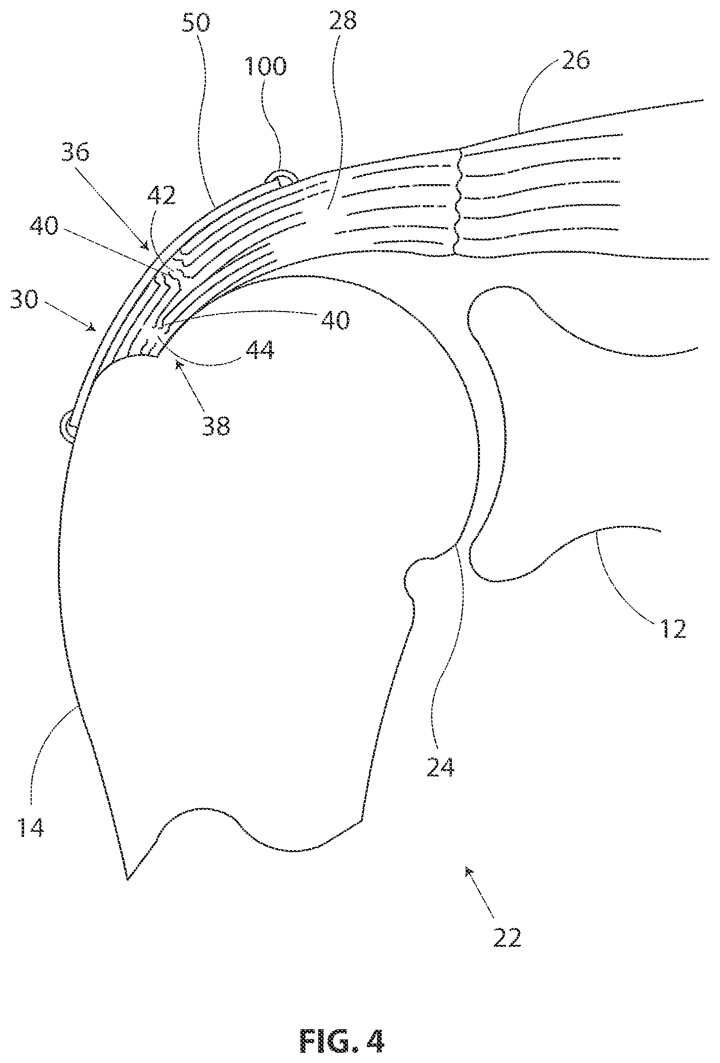
FIG. 4 is a stylized anterior view of a shoulder 22 including a humerus 14 and a scapula 12. In FIG. 4, a head 24 of humerus 14 is shown mating with a glenoid fossa of scapula 12 at a glenohumeral joint. A supraspinatus 26 is also shown in FIG. 4. This muscle (along with others) control the movement of humerus 14 relative to scapula 12. A distal tendon 28 of supraspinatus 26 meets humerus 14 at an insertion point 30.
In the embodiment of FIG. 4, distal tendon 28 includes a first damaged portion 36. A number of loose tendon fibers 40 in first damaged portion 36 are visible in FIG. 4. First damaged portion 36 includes a first tear 42 extending partially through distal tendon 28. First tear 42 may therefore be referred to as a partial thickness tear. With reference to FIG. 4, it will be appreciated that first tear 42 begins on the side of distal tendon 28 facing the subacromial bursa (shown in the previous Figure) and ends midway through distal tendon 28. Accordingly, first tear 42 may be referred to as a bursal side tear.
With reference to FIG. 4, it will be appreciated that distal tendon 28 includes a second damaged portion 38 located near insertion point 30. In the embodiment of FIG. 4, second damaged portion 38 of distal tendon 28 has become frayed and a number of loose tendon fibers 40 are visible in FIG. 4. Second damaged portion 38 of distal tendon 28 includes second tear 44. With reference to FIG. 4, it will be appreciated that second tear 44 begins on the side of distal tendon 28 facing the humerus 14. Accordingly, second damaged portion 38 may be referred to as an articular side tear.
In the embodiment of FIG. 4, a sheet-like implant 50 has been placed over the bursal side of distal tendon 28. With reference to FIG. 4, it will be appreciated that sheet-like implant 50 extends over insertion point 30, first tear 42 and second tear 44. Some useful methods in accordance with this detailed description may include placing a tendon repair implant on the bursal side of a tendon regardless of whether the tears being treated are on the bursal side, articular side or within the tendon. In some cases the exact location and nature of the tears being treated may be unknown. A tendon repair implant may be applied to the bursal side of a tendon to treat shoulder pain that is most likely caused by one or more partial thickness tears in the tendon. In the embodiment of FIG. 4, sheet-like implant 50 is fixed to distal tendon 28 and to humerus 14 by a plurality of staples 100 as described herein in detail.
FIG. 5 is a stylized perspective view illustrating an exemplary procedure for treating a shoulder 22 of a patient 20. The procedure illustrated in FIG. 5 may include, for example, fixing tendon repair implants to one or more tendons of shoulder 22. The tendons treated may be torn, partially torn, have internal micro-tears, be untorn, and/or be thinned due to age, injury or overuse.
Shoulder 22 of FIG. 5 has been inflated to create a cavity therein. In the exemplary embodiment of FIG. 5A, a fluid supply 52 is pumping a continuous flow of saline into the cavity. This flow of saline exits the cavity via a fluid drain 54. A camera 56 provides images from inside the cavity. The images provided by camera 56 may be viewed on a display 58.
Camera 56 may be used to visually inspect the tendons of shoulder 22 for damage. A tendon repair implant in accordance with this disclosure may be fixed to a bursal surface of the tendon regardless of whether there are visible signs of tendon damage. Applicants believe that the methods and apparatus of the present application and related devices may provide very beneficial therapeutic effect on a patient experiencing joint pain believed to be caused by internal microtears, but having no clear signs of tendon tears. By applying a tendon repair implant early before a full tear or other injury develops, the implant may cause the tendon to thicken and/or at least partially repair itself, thereby avoiding more extensive joint damage, pain, and the need for more extensive joint repair surgery.
A delivery system 60 can be seen extending from shoulder 22 in FIG. 5. Delivery system 60 comprises a sheath that is fixed to a handle. The sheath defines a lumen and a distal opening fluidly communicating the lumen. In the embodiment of FIG. 5, the distal opening of the sheath has been placed in fluid communication with the cavity created in shoulder 22.
A tendon repair implant is at least partially disposed in the lumen defined by the sheath of delivery system 60. Delivery system 60 can be used to place the tendon repair implant inside shoulder 22. Delivery system 60 can also be used to hold the tendon repair implant against the tendon. In some embodiments, the tendon repair implant is folded into a compact configuration when inside the lumen of the sheath. When this is the case, delivery system 60 may be used to unfold the tendon repair implant into an expanded shape.
The tendon repair implant may be fixed to the tendon while it is held against the tendon by delivery system 60. Various attachment elements may be used to fix the tendon repair implant to the tendon. Examples of attachment elements that may be suitable in some applications include sutures, tissue anchors, bone anchors, and staples. In the exemplary embodiment of FIG. 5, the shaft of a fixation tool 70 is shown extending into shoulder 22. In one exemplary embodiment, fixation tool 70 is capable of fixing the tendon repair implant to the tendon with one or more staples while the tendon repair implant is held against the tendon by delivery system 60.
FIG. 6 is a stylized perspective view of a shoulder 22 including a supraspinatus 26 having a distal tendon 28. With reference to FIG. 6, it will be appreciated that a tendon repair implant 50 has been fixed to a surface of distal tendon 28. Tendon repair implant 50 may comprise, for example, various sheet-like structures without deviating from the spirit and scope of the present detailed description. In some useful embodiments, the sheet-like structure may comprise a plurality of fibers. The fibers may be interlinked with one another. When this is the case, the sheet-like structure may comprise a plurality of apertures comprising the interstitial spaces between fibers. Various processes may be used to interlink the fibers with one another. Examples of processes that may be suitable in some applications including weaving, knitting, and braiding. In some embodiment, the sheet-like structure may comprise a laminate including multiple layers of film with each layer of film defining a plurality of micro-machined or formed holes. The sheet-like structure of the tendon repair implant may also comprise a plurality of electro-spun nanofiber filaments forming a composite sheet. Additionally, the sheet-like structure may comprise a synthetic sponge material that defines a plurality of pores. The sheet-like structure may also comprise a reticulated foam material. Reticulated foam materials that may be suitable in some applications are available from Biomerix Corporation of Freemont, Calif. which identifies these materials using the trademark BIOMATERIAL.TM..
Various attachment elements may be used to fix tendon repair implant 50 to distal tendon 28 without deviating from the spirit and scope of this detailed description. Examples of attachment elements that may be suitable in some applications include sutures, tissue anchors, bone anchors, and staples. In the exemplary embodiment of FIG. 6, a plurality of staples 100 are fixing tendon repair implant 50 to distal tendon 28. In some exemplary methods, a plurality of staples 100 may be applied using a fixation tool. The fixation tool may then be withdrawn from the body of the patient. Distal tendon 28 meets humerus 14 at an insertion point 30. With reference to FIG. 6, it will be appreciated that sheet-like implant 50 extends over insertion point 30. Tendon repair implant may be applied to distal tendon 28, for example, using the procedure illustrated in the previous Figure.
FIG. 7A, FIG. 7B, and FIG. 7C are multiple plan views illustrating an exemplary staple 100 in accordance with the present detailed description. FIG. 7A, FIG. 7B, and FIG. 7C may be collectively referred to as FIG. 7. A proximal direction is illustrated with an arrow P in FIG. 7. A distal direction is illustrated with a second arrow D in FIG. 7.
Staple 100 comprises a first arm 102A, a second arm 102B, and a bridge 104 extending from the proximal end of first arm 102A to the proximal end of second arm 102B. The distal end of first arm 102A abuts the proximal end of a first fluke 106A. Similarly, the distal end of second arm 102B abuts the proximal end of a second fluke 106B. In FIG. 7, first fluke 106A and second fluke 106B are shown extending distally from first arm 102A and second arm 102B, respectively. With reference to FIG. 7, it will be appreciated that first fluke 106A has a lateral extent that is larger than a lateral extent of first arm 102A. First fluke 106A is mounted eccentrically to first arm 102A in the embodiment of FIG. 7. Second fluke 106B is mounted eccentrically to second arm 102B and second fluke 106B has a lateral extent that is larger than a lateral extent of second arm 102B. First fluke 106A includes a first proximal surface 108A projecting at an outward angle in a proximal direction away from the distal end of first arm 102A. Second fluke 106B includes a second proximal surface 108B projecting at an outward angle in a proximal direction away from the distal end of second arm 102B.
With reference to FIG. 7A, it will be appreciated that first fluke 106A includes a first point 120A and a first barb 122A. Second fluke 106B includes a second point 120B and a second barb 122B. In FIG. 7, first point 120A and second point 120B are shown generally pointing in the distal direction indicated by arrow D. Also in FIG. 7, first barb 122A and second barb 122B are shown generally pointing in the proximal direction indicated by arrow P.
With reference to FIG. 7A it will be appreciated that first fluke 106A defines a first passageway 124A and second fluke 106B defines a second passageway 124B. In the exemplary embodiment of FIG. 7, first passageway 124A extends through first fluke 106A and second passageway 124B extends through second fluke 106B. It will be appreciated, however, that first passageway 124A may extend through other portions of staple 100 in some embodiments. Similarly, second passageway 124B may extend through other portions of staple 100 in some embodiments. With reference to FIG. 7B it will be appreciated that, first passageway 124A and second passageway 124B each have a generally square cross-sectional shape. It will be appreciated, however, that first passageway 124A and second passageway 124B may have various cross-sectional shapes without deviating from the spirit and scope of the present detailed description. Further, each passageway can extend partially through the length of each fluke rather than all the way through to provide a cavity rather than a passageway.
With reference to FIG. 7C, it will be appreciated that first barb 122A of first fluke 106A defines a first notch 126A. In the exemplary embodiment of FIG. 7, first notch 126A divides first barb 122A into a first sub-barb and a second sub-barb. Second barb 122B of second fluke 106B defines a second notch 126B. In the exemplary embodiment of FIG. 7, second notch 126B divides second barb 122B into a first sub-barb and a second sub-barb.
FIG. 8 is a perspective view showing staple 100 shown in the previous Figure. Staple 100 comprises a first arm 102A, a second arm 102B, and a bridge 104 extending from the proximal end of first arm 102A to the proximal end of second arm 102B. The distal end of first arm 102A abuts the proximal end of a first fluke 106A. With reference to FIG. 8 it will be appreciated that first fluke 106A defines a first passageway 124A. In the exemplary embodiment of FIG. 8, first passageway 124A has a generally square cross-sectional shape. It will be appreciated, however, that first passageway 124A may have various cross-sectional shapes without deviating from the spirit and scope of the present detailed description.
A second fluke 106B extends distally from second arm 102B with the proximal end of second fluke 106B abutting the distal end of second arm 102B. With reference to FIG. 8, it will be appreciated that second fluke 106B has a lateral extent that is larger than a lateral extent of second arm 102B. Second fluke 106B is mounted eccentrically to second arm 102B in the embodiment of FIG. 8. Similarly, first fluke 106A is mounted eccentrically to first arm 102A and first fluke 106A has a lateral extent that is larger than a lateral extent of first arm 102A.
A proximal direction is illustrated with an arrow P in FIG. 8. A distal direction is illustrated with a second arrow D in FIG. 8. With reference to FIG. 8A, it will be appreciated that first fluke 106A of first arm 102A includes a first point 120A and a first barb 122A. Second fluke 106B includes a second point 120B and a second barb 122B. In FIG. 8, first point 120A and second point 120B are shown generally pointing in the distal direction indicated by arrow D. Also in FIG. 8, first barb 122A and second barb 122B are shown generally pointing in the proximal direction indicated by arrow P. With reference to FIG. 8, it will be appreciated that first fluke 106A includes a first proximal surface 108A projecting at an outward angle in a proximal direction away from the distal end of first arm 102A. Second fluke 106B includes a second proximal surface 108B projecting at an outward angle in a proximal direction away from the distal end of second arm 102B.
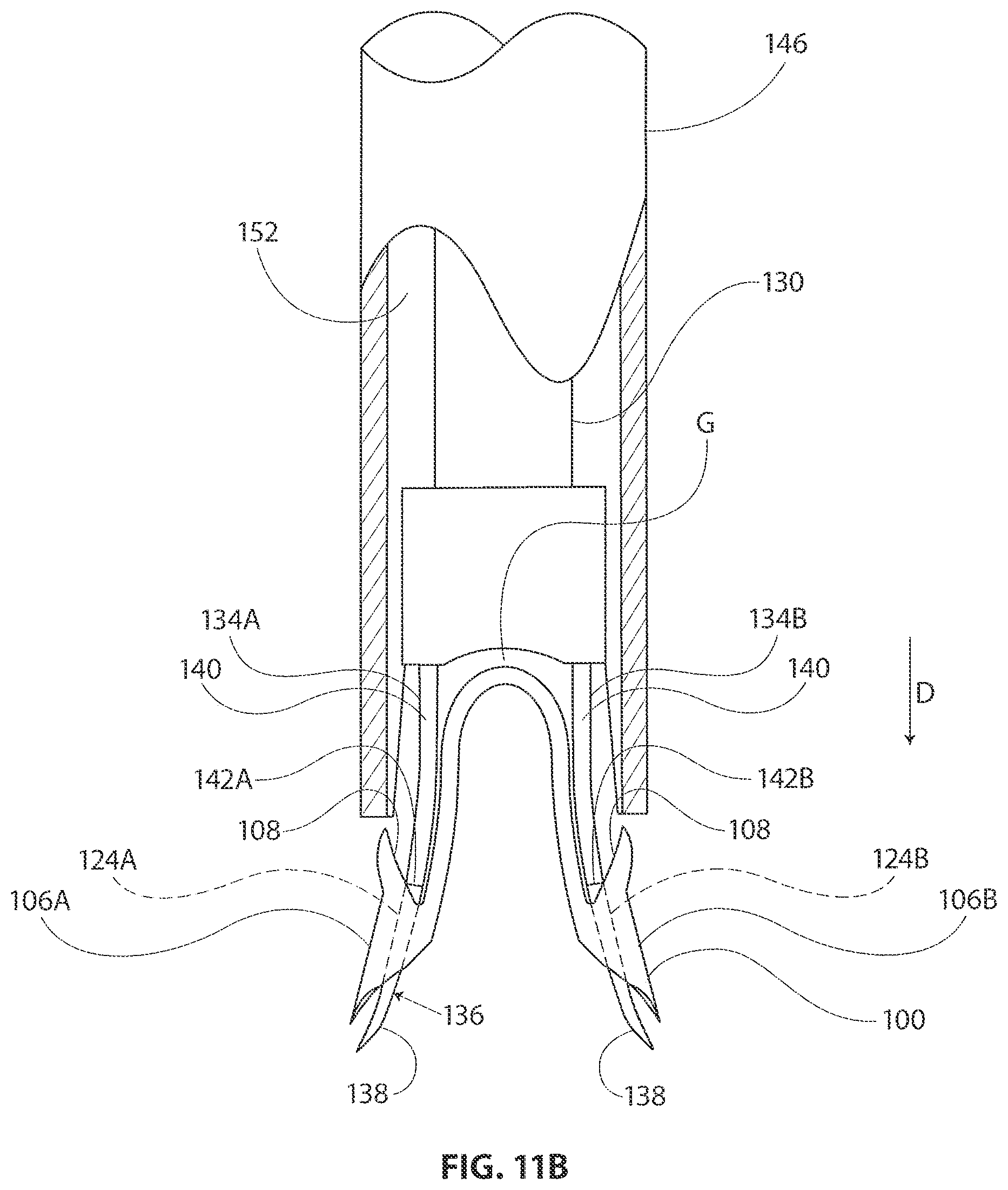
FIG. 9 is a perspective view showing a staple push rod 130 that may be used in conjunction with staple 100 shown in the previous Figure. Staple push rod 130 includes a shaft 132 and a pair of stakes 134 extending distally beyond a distal end of shaft 132. The distal direction is indicated with an arrow D in FIG. 9. Stakes 134 include a first stake 134A and a second stake 134B. First stake 134A and second stake 134B form a fork 136.
In the embodiment of FIG. 9, each stake 134 has a distal portion 138 and a proximal portion 140. In some useful embodiments, each distal portion 138 is dimensioned to extend into a passage defined by a staple. In the embodiment of FIG. 9, each proximal portion 140 has a width larger than a width of each distal portion 138 so that a shoulder of each proximal portion 140 contacts a proximal surface of the staple to apply pushing forces thereto. First stake 134A comprises a first shoulder 142A and second stake 134B comprises a second shoulder 142B. Although depicted as a shoulder to provide pushing force to the staple, other designs can be utilized. For example, any larger cross section proximal portion can provide a pushing force, such as a conical increase in profile. In the embodiment of FIG. 9, proximal portion 140 of first stake 134A and the proximal portion 140 of second stake 134B diverge from one another as they extend in distal direction D away from shaft 132. In some applications, this arrangement may cause pushing forces applied to two flukes of a staple to have a laterally outward component.
In FIG. 9, first stake 134A and second stake 134B are shown assuming a substantially unstressed state. It will be appreciated that first stake 134A and second stake 134B can be resiliently urged to assume shapes other than the shape shown in FIG. 9. For example, first stake 134A and second stake 134B may be urged together so that fork 136 can be inserted into a lumen having a diameter smaller than the distance between the distal points of first stake 134A and second stake 134B shown in FIG. 9.
FIG. 10A and FIG. 10B illustrate multiple plan views of an exemplary fixation tool 144 in accordance with the present detailed description. Fixation tool 144 incorporates staple push rod 130 and is useful in delivering staple 100. FIG. 10A and FIG. 10B may be referred to collectively as FIG. 10. It is customary to refer to multi-view projections using terms such as front view, top view, and side view. In accordance with this convention, FIG. 10A may be referred to as a top view of fixation tool 144 and FIG. 10B may be referred to as a side view of fixation tool 144. The terms top view and side view are used herein as a convenient method for differentiating between the views shown in FIG. 10. It will be appreciated that the elements shown in FIG. 10 may assume various orientations without deviating from the spirit and scope of this detailed description. Accordingly, the terms top view and side view should not be interpreted to limit the scope of the invention recited in the attached claims.
In the embodiment of FIG. 10, fixation tool 144 comprises a pilot member or fixation tool shaft 146 that is attached to a handle 148. Fixation tool shaft 146 comprises a wall 150 defining a lumen 152. With reference to FIG. 10, it will be appreciated that fixation tool shaft 146 includes a first prong 154A and a second prong 156B that extend distally beyond a distal end 158 of lumen 152.
In FIG. 10, a staple 100 can be seen residing in lumen 152 of fixation tool shaft 146. For purposes of illustration, a distal portion of fixation tool shaft 146 is enlarged in FIG. 10 to better show staple 100. Staple 100 comprises a first aim 102A, a second arm 102B, and a bridge 104 extending from the proximal end of first arm 102A to the proximal end of second arm 102B. The distal end of first arm 102A abuts the proximal end of a first fluke 106A. Similarly, the distal end of second arm 102B abuts the proximal end of a second fluke 106B. In FIG. 10, first fluke 106A and second fluke 106B are shown extending distally from first arm 102A and second arm 102B, respectively.
Staple push rod 130 includes a shaft 132 and a pair of stakes 134 extending distally beyond a distal end of shaft 132. The distal direction is indicated with an arrow D in FIG. 10. Stakes 134 include a first stake 134A and a second stake 134B. In FIG. 10, a distal portion of each stake 134 can be seen extending through a passageway defined by staple 100. In the embodiment of FIG. 10, a trigger 160 is pivotably coupled to handle 148 of fixation tool 144. Trigger 160 is operatively coupled to staple push rod 130. In operation, staple push rod 130 will be advanced and/or retracted in an axial direction when trigger 160 is pivoted relative to handle 148.
FIG. 11A is a further enlarged top view of a distal portion of fixation tool shaft 146 shown in the previous Figure. For purposes of illustration, fixation tool shaft 146 is shown in partial cross-section in FIG. 11A so that staple 100 is visible residing in lumen 152. With reference to FIG. 11A, it will be appreciated that staple 100 is disposed on a distal portion of staple push rod 130. Staple 100 comprises a first arm 102A, a second arm 102B, and a bridge 104 extending from the proximal end of first arm 102A to the proximal end of second arm 102B. The distal end of first arm 102A abuts the proximal end of a first fluke 106A. Similarly, the distal end of second arm 102B abuts the proximal end of a second fluke 106B. In FIG. 11, first fluke 106A and second fluke 106B are shown extending distally from first arm 102A and second aim 102B, respectively.
First fluke 106A of staple 100 defines a first passageway 124A. In FIG. 11A, a distal portion 138 of first stake 134A of staple push rod 130 can be seen extending through first passageway 124A defined by first fluke 106A. A distal portion 138 of second stake 134B of staple push rod 130 can be seen extending through a second passageway 124B defined by second fluke 106B of staple 100.
In FIG. 11A, a first shoulder 142A of first stake 134A is shown contacting proximal surface 108 of first fluke. Distal portion 138 of first stake 134A extends distally of first shoulder 142A and proximal portion 140 of first stake 134A extends proximally of first shoulder 142A. In some useful embodiments, the proximal portion of first stake 134A has a first thickness and the distal portion of first stake 134A has a second thickness different from the first thickness. In some particularly useful embodiments, the second thickness is less than the first thickness. In some applications, this may increase the flexibility of the distal portion of first stake 134A so that it bends more easily, and so that it withdraws from the staple with minimal force.
A second shoulder 142B of second stake 134B is shown contacting proximal surface 108 of second fluke 106 in FIG. 11A. A distal portion 138 of second stake 134B extends distally of second shoulder 142B and a proximal portion 140 of second stake 134B extends proximally of second shoulder 142B. In some useful embodiments, the proximal portion of second stake 134B has a first thickness and the distal portion of second stake 134B has a second thickness different from the first thickness. In some particularly useful embodiments, the second thickness is less than the first thickness. In some applications, this may increase the flexibility of the distal portion of first stake 134A so that it bends more easily, and so that it withdraws from the staple with minimal force.
With reference to FIG. 11A, it will be appreciated that there is a gap G between staple push rod 130 and bridge 104 of staple 100. In some applications, gap G allows staple 100 to be placed in tension without bridge 104 contacting staple push rod 130. Staple 100 may be placed in tension, for example, as staple 100 is advanced into a target tissue.
FIG. 11B is an additional top view showing a distal portion of fixation tool shaft 146, staple push rod 130, and staple 100. By comparing FIG. 11A and FIG. 11B, it will be appreciated that staple push rod 130 and staple 100 have been advanced in a distal direction D relative to fixation tool shaft 146. In FIG. 11B, staple 100 is shown extending out of lumen 152 defined by fixation tool shaft 146.
In FIG. 11B, a distal portion 138 of first stake 134A of staple push rod 130 can be seen extending through a first passageway 124A defined by first fluke 106A of staple 100. In FIG. 11B, a first shoulder 142A of first stake 134A is shown contacting proximal surface 108 of first fluke 106A. Distal portion 138 of first stake 134A extends distally of first shoulder 142A and proximal portion 140 of first stake 134A extends proximally of first shoulder 142A. In some useful embodiments, the proximal portion of first stake 134A has a first width and the distal portion of first stake 134A has a second width different from the first width. In some particularly useful embodiments, the first width is greater than the first width. The arrangement allows the proximal portion of stake to engage a proximal surface of the staple to apply pushing forces to the staple.
In FIG. 11B, a distal portion 138 of second stake 134B of staple push rod 130 can be seen extending through a second passageway 124B defined by second fluke 106B of staple 100. In FIG. 11B, a second shoulder 142B of second stake 134B is shown contacting proximal surface 108 of second fluke 106B. In the embodiment of FIG. 11B, proximal portion 140 of second stake 134B may apply pushing force to proximal surface 108 of second stake 134B. Proximal portion 140 of second stake 134B extends proximally of second shoulder 142B and distal portion 138 of second stake 134B extends distally of second shoulder 142B. In the embodiment of FIG. 11B, proximal portion 140 of second stake 134B has a width larger than the width of distal portion 138 of second stake 134B so that the shoulder 142 of second stake 134B contacts proximal surface 108 of second fluke 106B to apply pushing forces thereto.
In the embodiment of FIG. 11B, first stake 134A and second stake 134B are in a substantially unstressed state. It will be appreciated that first stake 134A and second stake 134B can be resiliently urged to assume shapes other than the shape shown in FIG. 11. For example, first stake 134A and second stake 134B may be urged together so that fork 136 of staple push rod 130 and staple 100 can be inserted into lumen 152 defined by fixation tool shaft 146.
With reference to FIG. 11B, it will be appreciated that there is a gap G between staple push rod 130 and bridge 104 of staple 100. In some applications, gap G allows staple 100 to be placed in tension without bridge 104 contacting staple push rod 130. In some applications, placing staple 100 under tension may urge first fluke 106 and second fluke 106 into orientations which lock staple 100 into a target tissue. For example, first fluke 106A and second fluke 106B may be rotated so that a barb of each fluke engages the target tissue. When this is the case, the tension on the staple may keep first fluke 106A and second fluke 106B in the rotated position. Also when this is the case, the barbs of the rotated flukes may inhibit staple pullout.
FIG. 12A through FIG. 12C are a sequence of plan views illustrating an exemplary method in accordance with the present detailed description. FIG. 12A, FIG. 12B, and FIG. 12C may be collectively referred to as FIG. 12. The exemplary method illustrated in FIG. 12 may be used, for example, to fix a tendon repair implant 50 to a target tissue T using a staple 100.
At FIG. 12A, a fixation tool 144 has been used to form a first pilot hole 162A and a second pilot hole 162B in target tissue T. In the embodiment of FIG. 12, fixation tool 144 includes a fixation tool shaft 146 comprising a wall 150 defining a lumen 152. With reference to FIG. 12, it will be appreciated that fixation tool shaft 146 includes a first prong 154A and a second prong 156B that extend distally beyond a distal end 158 of lumen 152. In the embodiment of FIG. 12A, first prong 154A and second prong 156B have been urged into tissue T to form first pilot hole 162A and second pilot hole 162B. In FIG. 12A a distally directed force F applied to fixation tool shaft 146 is illustrated using an arrow. Force F may be produced, for example, by pushing on a handle that is fixed to a proximal portion of fixation tool shaft 146. It will be appreciated that in some embodiments, such as the embodiment depicted in FIG. 6, one of the first and second pilot holes may be formed through the sheet-like implant and the target tissue, and the other pilot hole may be formed directly in the target tissue without passing through the sheet-like implant. In other words, in various embodiments staples may straddle the perimeter edge of the sheet-like implant (as shown in FIG. 6), may be applied adjacent to the perimeter, and/or be applied to a central region of the implant. In some embodiments, the staples may be used to attach the implant to soft tissue and/or to bone. In FIG. 12A, a staple 100 can be seen residing in lumen 152 of fixation tool shaft 146. For purposes of illustration, fixation tool shaft 146 is shown in partial cross-section in FIG. 12A so that staple 100 is visible residing in lumen 152. With reference to FIG. 12, it will be appreciated that staple 100 is carried by a fork 136 comprising a first stake 134A and a second stake 134B. In FIG. 12A, a distal portion of first stake 134A of staple push rod 130 can be seen extending through a first passageway defined by first fluke 106A. A distal portion of second stake 134B of staple push rod 130 can be seen extending through a second passageway defined by second fluke 106B of staple 100.
In some useful embodiments, each stake is positioned relative to a prong along an inner surface of fixation tool shaft 146 so that the stakes advance into the pilot holes when the stakes are moved in a distal direction. Staple push rod 130 is slidably disposed within lumen 152 defined by along fixation tool shaft 146. Fixation tool 144 includes a mechanism that is capable of creating relative axial motion between staple push rod 130 and fixation tool shaft 146 so that staple push rod 130 slides along fixation tool shaft 146.
At FIG. 12B, relative motion has been created between staple push rod 130 and fixation tool shaft 146 while distally directed force F has been continuously applied to fixation tool shaft 146. By comparing FIG. 12B and FIG. 12A, it will be appreciated that first stake 134A and second stake 134B have been advanced in a distal direction D. With reference to FIG. 12, it will also be appreciated that first stake 134A and second stake 134B have advanced into first pilot hole 162A and second pilot hole 162B, respectively. In FIG. 12B, first fluke 106A is shown residing in first pilot hole 162. Second fluke 106B is residing in second pilot hole 162 in the embodiment of FIG. 12B.
At FIG. 12C, additional relative motion has been created between staple push rod 130 and fixation tool shaft 146 while distally directed force F has been continuously applied to fixation tool shaft 146. By comparing FIG. 12C and FIG. 12B, it will be appreciated that the relative motion between staple push rod 130 and fixation tool shaft 146 has moved fixation tool shaft 146 in a proximal direction P.
By comparing FIG. 12C and FIG. 12B, it will also be appreciated that first arm 102A of staple 100 has been bent and first fluke 106A has been rotated to a toggled position. In the exemplary embodiment of FIG. 12C, force applied to first fluke 106A by first shoulder 142A has caused first fluke 106A to rotate. Also in the embodiment of FIG. 12C, the rotation of first fluke 106A has caused some bending in the distal portion 138 of first stake 134A. With continuing reference to FIG. 12C and FIG. 12B, it will be appreciated that second arm 102B of staple 100 has been bent and second fluke 106A has been rotated to a toggled position. In the exemplary embodiment of FIG. 12C, force applied to second fluke 106b by second shoulder 142B has caused second fluke 106B to rotate. Also in the embodiment of FIG. 12C, the rotation of second fluke 106B has caused some bending in the distal portion 138 of second stake 134B.
With reference to FIG. 12C, it will be appreciated that a first through hole 164A and a second through hole 164B have been formed in tendon repair implant 50. In the embodiment of FIG. 12, first through hole 164A and a second through hole 164B were created by urging first prong 154A and second prong 156B of fixation tool shaft 146 through tendon repair implant 50.
FIG. 13A, FIG. 13B, and FIG. 13C are multiview projections illustrating a fixation tool shaft 146 shown in the previous Figures. FIG. 13D is a cross-sectional view of fixation tool shaft 146 sectioned along cutting plane D-D illustrated in FIG. 13C. These Figures may be collectively referred to as FIG. 13. Fixation tool shaft 146 of FIG. 13 comprises a wall 150 defining a lumen 152. A first prong 154A and a second prong 156B of fixation tool shaft 146 extend distally beyond a distal end 158 of lumen 152.
With reference to FIG. 13, it will be appreciated that fixation tool shaft 146 comprises a proximal portion 170, a distal portion 168 and an intermediate portion 166 disposed between proximal portion 170 and distal portion 168. In the embodiment of FIG. 13, distal portion 168 has an axial extent DA, a major lateral extent LA and a minor lateral extent LB. With reference to FIG. 13, it will be appreciated that axial extent DA is greater than both minor lateral extent LB and major lateral extent LA.
FIG. 14 is an enlarged axial view of fixation tool shaft 146 shown in the previous Figure. With reference to FIG. 14, it will be appreciated that proximal portion 170 of fixation tool shaft 146 comprises a wall 150 having an outer surface 172. In FIG. 14, outer surface 172 is illustrated using a circle. Thus, it will be appreciated that proximal portion 170 of fixation tool shaft 146 has a generally cylindrical outer shape in the exemplary embodiment of FIG. 14. In the exemplary embodiment of FIG. 14, fixation tool shaft 146 has a generally uniform wall thickness. Accordingly, the shape of proximal portion 170 may be generally described as a cylindrical tube. The shape of distal portion 168 may be described as a cylindrical-tube that has been partially flattened. In the exemplary embodiment of FIG. 14, distal portion 168 of fixation tool shaft 146 has a major lateral extent LA and a minor lateral extent LB. With reference to FIG. 14, it will be appreciated that major lateral extent LA is greater than minor lateral extent LB.
FIG. 15 is an additional enlarged axial view of fixation tool shaft 146. With reference to FIG. 15, it will be appreciated that distal portion 168 of fixation tool shaft 146 comprises a first major side SA, a second major side SB, a first minor side SC, and a second minor side SD. In the exemplary embodiment of FIG. 15, each minor side has a first central radius RA and each major side has a second central radius RB. With reference to FIG. 15, it will be appreciated that second central radius RB is greater than first central radius RA. In the exemplary embodiment of FIG. 15, first major side SA, second major side SB, first minor side SC, and second minor side SD each have a generally convex shape. In the exemplary embodiment of FIG. 15, each minor side is generally more convex than each major side.
FIG. 16 is an exploded isometric view of an exemplary fixation tool 144 in accordance with this detailed description. In the embodiment of FIG. 16, fixation tool 144 comprises a fixation tool shaft 146 and a handle 148. In FIG. 16, handle 148 is exploded into two pieces. A proximal portion of fixation tool shaft 146 is fixed to handle 148 when fixation tool 144 is in an assembled state. Fixation tool shaft 146 comprises a wall 150 defining a lumen 152.
When fixation tool 144 is in an assembled state a staple push rod 130 extends into lumen 152 of fixation tool shaft 146. Staple push rod 130 comprises a fork 136 and a shaft 132. Fork 136 comprises a first stake 134A and a second stake 134B. Shaft 132 is coupled between fork 136 and a lever 174. Lever 174 is coupled to a trigger 160. Trigger 160 is pivotably coupled to handle 148 of fixation tool 144 when fixation tool 144 is in an assembled state. In operation, staple push rod 130 will be advanced and/or retracted in an axial direction when trigger 160 is pivoted relative to handle 148.
While exemplary embodiments of the present invention have been shown and described, modifications may be made, and it is therefore intended in the appended claims and subsequently filed claims to cover all such changes and modifications which fall within the true spirit and scope of the invention.
* * * * *
References
D00000
D00001
D00002
D00003
D00004
D00005
D00006
D00007
D00008
D00009
D00010
D00011
D00012

D00013

D00014

D00015
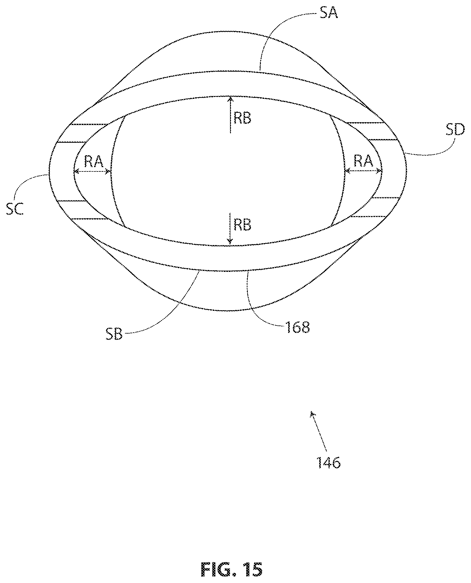
D00016

XML
uspto.report is an independent third-party trademark research tool that is not affiliated, endorsed, or sponsored by the United States Patent and Trademark Office (USPTO) or any other governmental organization. The information provided by uspto.report is based on publicly available data at the time of writing and is intended for informational purposes only.
While we strive to provide accurate and up-to-date information, we do not guarantee the accuracy, completeness, reliability, or suitability of the information displayed on this site. The use of this site is at your own risk. Any reliance you place on such information is therefore strictly at your own risk.
All official trademark data, including owner information, should be verified by visiting the official USPTO website at www.uspto.gov. This site is not intended to replace professional legal advice and should not be used as a substitute for consulting with a legal professional who is knowledgeable about trademark law.