Surgical instrument
Woodruff , et al. J
U.S. patent number 10,524,854 [Application Number 14/947,449] was granted by the patent office on 2020-01-07 for surgical instrument. This patent grant is currently assigned to Ethicon LLC. The grantee listed for this patent is Ethicon Endo-Surgery, Inc.. Invention is credited to Donna L. Korvick, David K. Norvell, Gwendolyn P. Payne, Patrick A. Weizman, Scott A. Woodruff, Aron O. Zingman.


View All Diagrams
| United States Patent | 10,524,854 |
| Woodruff , et al. | January 7, 2020 |
Surgical instrument
Abstract
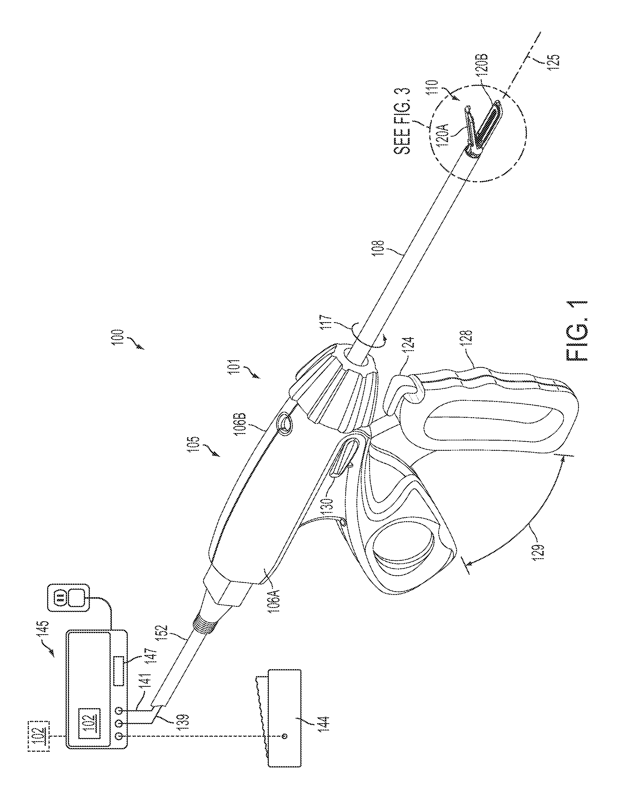
A surgical instrument can comprise a first jaw and second jaw, wherein the first jaw is movable relative to the second jaw to capture tissue having a tissue thickness. A tissue cutting force monitor is configured to determine the tissue thickness of the captured tissue and communicate the tissue thickness to a controller, wherein the controller is configured to adjust the speed of a tissue-cutting element during a cutting portion of a firing stroke based on the tissue thickness communicated from the tissue cutting force monitor. The controller is configured to reduce the speed of the tissue-cutting element when the tissue cutting force monitor communicates a thicker tissue thickness to the controller. The controller is configured to increase the speed of the tissue-cutting element when the tissue cutting force monitor communicates a thinner tissue thickness to the controller.
| Inventors: | Woodruff; Scott A. (Boston, MA), Weizman; Patrick A. (Liberty Township, OH), Payne; Gwendolyn P. (Cincinnati, OH), Korvick; Donna L. (Bridgewater, NJ), Norvell; David K. (Monroe, OH), Zingman; Aron O. (Cambridge, MA) | ||||||||||
|---|---|---|---|---|---|---|---|---|---|---|---|
| Applicant: |
|
||||||||||
| Assignee: | Ethicon LLC (Guaynabo,
PR) |
||||||||||
| Family ID: | 45494210 | ||||||||||
| Appl. No.: | 14/947,449 | ||||||||||
| Filed: | November 20, 2015 |
Prior Publication Data
| Document Identifier | Publication Date | |
|---|---|---|
| US 20160074108 A1 | Mar 17, 2016 | |
Related U.S. Patent Documents
| Application Number | Filing Date | Patent Number | Issue Date | ||
|---|---|---|---|---|---|
| 12842507 | Jul 23, 2010 | 9192431 | |||
| Current U.S. Class: | 1/1 |
| Current CPC Class: | A61B 18/1447 (20130101); A61B 18/1445 (20130101); A61B 2018/00589 (20130101); A61B 2018/00309 (20130101); A61B 2017/320094 (20170801); A61B 2018/00702 (20130101); A61B 2018/00619 (20130101); A61B 2018/0063 (20130101); A61B 2018/00601 (20130101); A61B 2017/320095 (20170801); A61B 2018/1455 (20130101); A61B 2018/00773 (20130101); A61B 2018/00196 (20130101); A61B 2018/00791 (20130101); A61B 2017/320093 (20170801); A61B 2018/00875 (20130101) |
| Current International Class: | A61B 18/14 (20060101); A61B 17/32 (20060101); A61B 18/00 (20060101) |
References Cited [Referenced By]
U.S. Patent Documents
| 969528 | September 1910 | Disbrow |
| 1570025 | January 1926 | Young |
| 1813902 | July 1931 | Bovie |
| 2188497 | January 1940 | Calva |
| 2366274 | January 1945 | Luth et al. |
| 2425245 | August 1947 | Johnson |
| 2442966 | June 1948 | Wallace |
| 2458152 | January 1949 | Eakins |
| 2510693 | June 1950 | Green |
| 2597564 | May 1952 | Bugg |
| 2704333 | March 1955 | Calosi et al. |
| 2736960 | March 1956 | Armstrong |
| 2748967 | June 1956 | Roach |
| 2845072 | July 1958 | Shafer |
| 2849788 | September 1958 | Creek |
| 2867039 | January 1959 | Zach |
| 2874470 | February 1959 | Richards |
| 2990616 | July 1961 | Balamuth et al. |
| RE25033 | August 1961 | Balamuth et al. |
| 3015961 | January 1962 | Roney |
| 3033407 | May 1962 | Alfons |
| 3053124 | September 1962 | Balamuth et al. |
| 3082805 | March 1963 | Royce |
| 3166971 | January 1965 | Stoecker |
| 3322403 | May 1967 | Murphy |
| 3432691 | March 1969 | Shoh |
| 3433226 | March 1969 | Boyd |
| 3489930 | January 1970 | Shoh |
| 3513848 | May 1970 | Winston et al. |
| 3514856 | June 1970 | Camp et al. |
| 3525912 | August 1970 | Wallin |
| 3526219 | September 1970 | Balamuth |
| 3554198 | January 1971 | Tatoian et al. |
| 3580841 | May 1971 | Cadotte et al. |
| 3606682 | September 1971 | Camp et al. |
| 3614484 | October 1971 | Shoh |
| 3616375 | October 1971 | Inoue |
| 3629726 | December 1971 | Popescu |
| 3636943 | January 1972 | Balamuth |
| 3668486 | June 1972 | Silver |
| 3702948 | November 1972 | Balamuth |
| 3703651 | November 1972 | Blowers |
| 3776238 | December 1973 | Peyman et al. |
| 3777760 | December 1973 | Essner |
| 3805787 | April 1974 | Banko |
| 3809977 | May 1974 | Balamuth et al. |
| 3830098 | August 1974 | Antonevich |
| 3854737 | December 1974 | Gilliam, Sr. |
| 3862630 | January 1975 | Balamuth |
| 3875945 | April 1975 | Friedman |
| 3885438 | May 1975 | Harris, Sr. et al. |
| 3900823 | August 1975 | Sokal et al. |
| 3918442 | November 1975 | Nikolaev et al. |
| 3924335 | December 1975 | Balamuth et al. |
| 3946738 | March 1976 | Newton et al. |
| 3955859 | May 1976 | Stella et al. |
| 3956826 | May 1976 | Perdreaux, Jr. |
| 4005714 | February 1977 | Hiltebrandt |
| 4012647 | March 1977 | Balamuth et al. |
| 4034762 | July 1977 | Cosens et al. |
| 4058126 | November 1977 | Leveen |
| 4074719 | February 1978 | Semm |
| 4156187 | May 1979 | Murry et al. |
| 4167944 | September 1979 | Banko |
| 4188927 | February 1980 | Harris |
| 4200106 | April 1980 | Douvas et al. |
| 4203430 | May 1980 | Takahashi |
| 4203444 | May 1980 | Bonnell et al. |
| 4220154 | September 1980 | Semm |
| 4237441 | December 1980 | van Konynenburg et al. |
| 4281785 | August 1981 | Brooks |
| 4300083 | November 1981 | Heiges |
| 4302728 | November 1981 | Nakamura |
| 4304987 | December 1981 | van Konynenburg |
| 4306570 | December 1981 | Matthews |
| 4314559 | February 1982 | Allen |
| 4445063 | April 1984 | Smith |
| 4463759 | August 1984 | Garito et al. |
| 4491132 | January 1985 | Aikins |
| 4492231 | January 1985 | Auth |
| 4494759 | January 1985 | Kieffer |
| 4504264 | March 1985 | Kelman |
| 4512344 | April 1985 | Barber |
| 4526571 | July 1985 | Wuchinich |
| 4535773 | August 1985 | Yoon |
| 4541638 | September 1985 | Ogawa et al. |
| 4545374 | October 1985 | Jacobson |
| 4545926 | October 1985 | Fouts, Jr. et al. |
| 4549147 | October 1985 | Kondo |
| 4550870 | November 1985 | Krumme et al. |
| 4553544 | November 1985 | Nomoto et al. |
| 4562838 | January 1986 | Walker |
| 4574615 | March 1986 | Bower et al. |
| 4582236 | April 1986 | Hirose |
| 4617927 | October 1986 | Manes |
| 4633119 | December 1986 | Thompson |
| 4634420 | January 1987 | Spinosa et al. |
| 4640279 | February 1987 | Beard |
| 4641053 | February 1987 | Takeda |
| 4646738 | March 1987 | Trott |
| 4646756 | March 1987 | Watmough et al. |
| 4649919 | March 1987 | Thimsen et al. |
| 4662068 | May 1987 | Polonsky |
| 4674502 | June 1987 | Imonti |
| 4694835 | September 1987 | Strand |
| 4708127 | November 1987 | Abdelghani |
| 4712722 | December 1987 | Hood et al. |
| 4735603 | April 1988 | Goodson et al. |
| 4761871 | August 1988 | O'Connor et al. |
| 4808154 | February 1989 | Freeman |
| 4819635 | April 1989 | Shapiro |
| 4827911 | May 1989 | Broadwin et al. |
| 4830462 | May 1989 | Karny et al. |
| 4832683 | May 1989 | Idemoto et al. |
| 4836186 | June 1989 | Scholz |
| 4838853 | June 1989 | Parisi |
| 4844064 | July 1989 | Thimsen et al. |
| 4849133 | July 1989 | Yoshida et al. |
| 4850354 | July 1989 | McGurk-Burleson et al. |
| 4852578 | August 1989 | Companion et al. |
| 4860745 | August 1989 | Farin et al. |
| 4862890 | September 1989 | Stasz et al. |
| 4865159 | September 1989 | Jamison |
| 4867157 | September 1989 | McGurk-Burleson et al. |
| 4878493 | November 1989 | Pasternak et al. |
| 4880015 | November 1989 | Nierman |
| 4881550 | November 1989 | Kothe |
| 4896009 | January 1990 | Pawlowski |
| 4903696 | February 1990 | Stasz et al. |
| 4910389 | March 1990 | Sherman et al. |
| 4915643 | April 1990 | Samejima et al. |
| 4920978 | May 1990 | Colvin |
| 4922902 | May 1990 | Wuchinich et al. |
| 4936842 | June 1990 | D'Amelio et al. |
| 4954960 | September 1990 | Lo et al. |
| 4965532 | October 1990 | Sakurai |
| 4979952 | December 1990 | Kubota et al. |
| 4981756 | January 1991 | Rhandhawa |
| 5001649 | March 1991 | Lo et al. |
| 5013956 | May 1991 | Kurozumi et al. |
| 5015227 | May 1991 | Broadwin et al. |
| 5020514 | June 1991 | Heckele |
| 5026370 | June 1991 | Lottick |
| 5026387 | June 1991 | Thomas |
| 5035695 | July 1991 | Weber, Jr. et al. |
| 5042707 | August 1991 | Taheri |
| 5061269 | October 1991 | Muller |
| 5075839 | December 1991 | Fisher et al. |
| 5084052 | January 1992 | Jacobs |
| 5099840 | March 1992 | Goble et al. |
| 5104025 | April 1992 | Main et al. |
| 5105117 | April 1992 | Yamaguchi |
| 5106538 | April 1992 | Barma et al. |
| 5108383 | April 1992 | White |
| 5109819 | May 1992 | Custer et al. |
| 5112300 | May 1992 | Ureche |
| 5113139 | May 1992 | Furukawa |
| 5123903 | June 1992 | Quaid et al. |
| 5126618 | June 1992 | Takahashi et al. |
| D327872 | July 1992 | McMills et al. |
| 5152762 | October 1992 | McElhenney |
| 5156633 | October 1992 | Smith |
| 5160334 | November 1992 | Billings et al. |
| 5162044 | November 1992 | Gahn et al. |
| 5163421 | November 1992 | Bernstein et al. |
| 5163537 | November 1992 | Radev |
| 5163945 | November 1992 | Ortiz et al. |
| 5167619 | December 1992 | Wuchinich |
| 5167725 | December 1992 | Clark et al. |
| 5172344 | December 1992 | Ehrlich |
| 5174276 | December 1992 | Crockard |
| D332660 | January 1993 | Rawson et al. |
| 5176677 | January 1993 | Wuchinich |
| 5176695 | January 1993 | Dulebohn |
| 5184605 | February 1993 | Grzeszykowski |
| 5188102 | February 1993 | Idemoto et al. |
| D334173 | March 1993 | Liu et al. |
| 5190517 | March 1993 | Zieve et al. |
| 5190541 | March 1993 | Abele et al. |
| 5196007 | March 1993 | Ellman et al. |
| 5205459 | April 1993 | Brinkerhoff et al. |
| 5209719 | May 1993 | Baruch et al. |
| 5213569 | May 1993 | Davis |
| 5214339 | May 1993 | Naito |
| 5217460 | June 1993 | Knoepfler |
| 5218529 | June 1993 | Meyer et al. |
| 5221282 | June 1993 | Wuchinich |
| 5222937 | June 1993 | Kagawa |
| 5226909 | July 1993 | Evans et al. |
| 5226910 | July 1993 | Kajiyama et al. |
| 5231989 | August 1993 | Middleman et al. |
| 5234428 | August 1993 | Kaufman |
| 5241236 | August 1993 | Sasaki et al. |
| 5241968 | September 1993 | Slater |
| 5242339 | September 1993 | Thornton |
| 5242460 | September 1993 | Klein et al. |
| 5246003 | September 1993 | DeLonzor |
| 5254129 | October 1993 | Alexander |
| 5257988 | November 1993 | L'Esperance, Jr. |
| 5258006 | November 1993 | Rydell et al. |
| 5261922 | November 1993 | Hood |
| 5263957 | November 1993 | Davison |
| 5264925 | November 1993 | Shipp et al. |
| 5275166 | January 1994 | Vaitekunas et al. |
| 5275607 | January 1994 | Lo et al. |
| 5275609 | January 1994 | Pingleton et al. |
| 5282800 | February 1994 | Foshee et al. |
| 5282817 | February 1994 | Hoogeboom et al. |
| 5285795 | February 1994 | Ryan et al. |
| 5285945 | February 1994 | Brinkerhoff et al. |
| 5290286 | March 1994 | Parins |
| 5300068 | April 1994 | Rosar et al. |
| 5304115 | April 1994 | Pflueger et al. |
| D347474 | May 1994 | Olson |
| 5307976 | May 1994 | Olson et al. |
| 5309927 | May 1994 | Welch |
| 5312023 | May 1994 | Green et al. |
| 5312425 | May 1994 | Evans et al. |
| 5318563 | June 1994 | Malis et al. |
| 5318564 | June 1994 | Eggers |
| 5318589 | June 1994 | Lichtman |
| 5322055 | June 1994 | Davison et al. |
| 5324299 | June 1994 | Davison et al. |
| 5326013 | July 1994 | Green et al. |
| 5326342 | July 1994 | Pflueger et al. |
| 5330471 | July 1994 | Eggers |
| 5330502 | July 1994 | Hassler et al. |
| 5339723 | August 1994 | Huitema |
| 5342356 | August 1994 | Ellman et al. |
| 5342359 | August 1994 | Rydell |
| 5344420 | September 1994 | Hilal et al. |
| 5345937 | September 1994 | Middleman et al. |
| 5346502 | September 1994 | Estabrook et al. |
| 5353474 | October 1994 | Good et al. |
| 5357164 | October 1994 | Imabayashi et al. |
| 5357423 | October 1994 | Weaver et al. |
| 5359994 | November 1994 | Krauter et al. |
| 5361583 | November 1994 | Huitema |
| 5366466 | November 1994 | Christian et al. |
| 5368557 | November 1994 | Nita et al. |
| 5370645 | December 1994 | Klicek et al. |
| 5371429 | December 1994 | Manna |
| 5374813 | December 1994 | Shipp |
| D354564 | January 1995 | Medema |
| 5381067 | January 1995 | Greenstein et al. |
| 5383874 | January 1995 | Jackson et al. |
| 5387207 | February 1995 | Dyer et al. |
| 5387215 | February 1995 | Fisher |
| 5389098 | February 1995 | Tsuruta et al. |
| 5394187 | February 1995 | Shipp |
| 5395312 | March 1995 | Desai |
| 5395363 | March 1995 | Billings et al. |
| 5395364 | March 1995 | Anderhub et al. |
| 5396266 | March 1995 | Brimhall |
| 5396900 | March 1995 | Slater et al. |
| 5400267 | March 1995 | Denen et al. |
| 5403312 | April 1995 | Yates et al. |
| 5403334 | April 1995 | Evans et al. |
| 5408268 | April 1995 | Shipp |
| D358887 | May 1995 | Feinberg |
| 5411481 | May 1995 | Allen et al. |
| 5417709 | May 1995 | Slater |
| 5419761 | May 1995 | Narayanan et al. |
| 5421829 | June 1995 | Olichney et al. |
| 5423844 | June 1995 | Miller |
| 5428504 | June 1995 | Bhatla |
| 5429131 | July 1995 | Scheinman et al. |
| 5438997 | August 1995 | Sieben et al. |
| 5441499 | August 1995 | Fritzsch |
| 5443463 | August 1995 | Stern et al. |
| 5445638 | August 1995 | Rydell et al. |
| 5445639 | August 1995 | Kuslich et al. |
| 5449370 | September 1995 | Vaitekunas |
| 5451053 | September 1995 | Garrido |
| 5451220 | September 1995 | Ciervo |
| 5451227 | September 1995 | Michaelson |
| 5456684 | October 1995 | Schmidt et al. |
| 5458598 | October 1995 | Feinberg et al. |
| 5465895 | November 1995 | Knodel et al. |
| 5471988 | December 1995 | Fujio et al. |
| 5472443 | December 1995 | Cordis et al. |
| 5476479 | December 1995 | Green et al. |
| 5478003 | December 1995 | Green et al. |
| 5480409 | January 1996 | Riza |
| 5483501 | January 1996 | Park et al. |
| 5484436 | January 1996 | Eggers et al. |
| 5486162 | January 1996 | Brumbach |
| 5486189 | January 1996 | Mudry et al. |
| 5490860 | February 1996 | Middle et al. |
| 5496317 | March 1996 | Goble et al. |
| 5500216 | March 1996 | Julian et al. |
| 5501654 | March 1996 | Failla et al. |
| 5504650 | April 1996 | Katsui et al. |
| 5505693 | April 1996 | Mackool |
| 5507297 | April 1996 | Slater et al. |
| 5507738 | April 1996 | Ciervo |
| 5509922 | April 1996 | Aranyi et al. |
| 5511556 | April 1996 | DeSantis |
| 5520704 | May 1996 | Castro et al. |
| 5522839 | June 1996 | Pilling |
| 5527331 | June 1996 | Kresch et al. |
| 5531744 | July 1996 | Nardella et al. |
| 5540681 | July 1996 | Strul et al. |
| 5540693 | July 1996 | Fisher |
| 5542916 | August 1996 | Hirsch et al. |
| 5548286 | August 1996 | Craven |
| 5549637 | August 1996 | Crainich |
| 5553675 | September 1996 | Pitzen et al. |
| 5558671 | September 1996 | Yates |
| 5562609 | October 1996 | Brumbach |
| 5562610 | October 1996 | Brumbach |
| 5562659 | October 1996 | Morris |
| 5563179 | October 1996 | Stone et al. |
| 5569164 | October 1996 | Lurz |
| 5571121 | November 1996 | Heifetz |
| 5573424 | November 1996 | Poppe |
| 5573534 | November 1996 | Stone |
| 5577654 | November 1996 | Bishop |
| 5584830 | December 1996 | Ladd et al. |
| 5591187 | January 1997 | Dekel |
| 5593414 | January 1997 | Shipp et al. |
| 5599350 | February 1997 | Schulze et al. |
| 5600526 | February 1997 | Russell et al. |
| 5601601 | February 1997 | Tal et al. |
| 5603773 | February 1997 | Campbell |
| 5607436 | March 1997 | Pratt et al. |
| 5607450 | March 1997 | Zvenyatsky et al. |
| 5609573 | March 1997 | Sandock |
| 5611813 | March 1997 | Lichtman |
| 5618304 | April 1997 | Hart et al. |
| 5618307 | April 1997 | Donlon et al. |
| 5618492 | April 1997 | Auten et al. |
| 5620447 | April 1997 | Smith et al. |
| 5624452 | April 1997 | Yates |
| 5626587 | May 1997 | Bishop et al. |
| 5626595 | May 1997 | Sklar et al. |
| 5628760 | May 1997 | Knoepfler |
| 5630420 | May 1997 | Vaitekunas |
| 5632432 | May 1997 | Schulze et al. |
| 5632717 | May 1997 | Yoon |
| 5640741 | June 1997 | Yano |
| D381077 | July 1997 | Hunt |
| 5647871 | July 1997 | Levine et al. |
| 5649937 | July 1997 | Bito et al. |
| 5651780 | July 1997 | Jackson et al. |
| 5653713 | August 1997 | Michelson |
| 5655100 | August 1997 | Ebrahim et al. |
| 5658281 | August 1997 | Heard |
| 5662662 | September 1997 | Bishop et al. |
| 5662667 | September 1997 | Knodel |
| 5665085 | September 1997 | Nardella |
| 5665100 | September 1997 | Yoon |
| 5669922 | September 1997 | Hood |
| 5674219 | October 1997 | Monson et al. |
| 5674220 | October 1997 | Fox et al. |
| 5674235 | October 1997 | Parisi |
| 5678568 | October 1997 | Uchikubo et al. |
| 5688270 | November 1997 | Yates et al. |
| 5690269 | November 1997 | Bolanos et al. |
| 5693051 | December 1997 | Schulze et al. |
| 5694936 | December 1997 | Fujimoto et al. |
| 5695510 | December 1997 | Hood |
| 5700261 | December 1997 | Brinkerhoff |
| 5704534 | January 1998 | Huitema et al. |
| 5707369 | January 1998 | Vaitekunas et al. |
| 5709680 | January 1998 | Yates et al. |
| 5711472 | January 1998 | Bryan |
| 5713896 | February 1998 | Nardella |
| 5715817 | February 1998 | Stevens-Wright et al. |
| 5716366 | February 1998 | Yates |
| 5717306 | February 1998 | Shipp |
| 5720742 | February 1998 | Zacharias |
| 5720744 | February 1998 | Eggleston et al. |
| 5723970 | March 1998 | Bell |
| 5728130 | March 1998 | Ishikawa et al. |
| 5730752 | March 1998 | Alden et al. |
| 5733074 | March 1998 | Stock et al. |
| 5735848 | April 1998 | Yates et al. |
| 5741226 | April 1998 | Strukel et al. |
| 5743906 | April 1998 | Parins et al. |
| 5752973 | May 1998 | Kieturakis |
| 5755717 | May 1998 | Yates et al. |
| 5762255 | June 1998 | Chrisman et al. |
| 5766164 | June 1998 | Mueller et al. |
| 5772659 | June 1998 | Becker et al. |
| 5776155 | July 1998 | Beaupre et al. |
| 5779701 | July 1998 | McBrayer et al. |
| 5782834 | July 1998 | Lucey et al. |
| 5792135 | August 1998 | Madhani et al. |
| 5792138 | August 1998 | Shipp |
| 5792165 | August 1998 | Klieman et al. |
| 5796188 | August 1998 | Bays |
| 5797941 | August 1998 | Schulze et al. |
| 5797958 | August 1998 | Yoon |
| 5797959 | August 1998 | Castro et al. |
| 5800432 | September 1998 | Swanson |
| 5800449 | September 1998 | Wales |
| 5805140 | September 1998 | Rosenberg et al. |
| 5807393 | September 1998 | Williamson, IV et al. |
| 5808396 | September 1998 | Boukhny |
| 5810811 | September 1998 | Yates et al. |
| 5810859 | September 1998 | DiMatteo et al. |
| 5817033 | October 1998 | DeSantis et al. |
| 5817084 | October 1998 | Jensen |
| 5817093 | October 1998 | Williamson, IV et al. |
| 5817119 | October 1998 | Klieman et al. |
| 5823197 | October 1998 | Edwards |
| 5827271 | October 1998 | Buysse et al. |
| 5827323 | October 1998 | Klieman et al. |
| 5828160 | October 1998 | Sugishita |
| 5833696 | November 1998 | Whitfield et al. |
| 5836897 | November 1998 | Sakurai et al. |
| 5836909 | November 1998 | Cosmescu |
| 5836943 | November 1998 | Miller, III |
| 5836957 | November 1998 | Schulz et al. |
| 5836990 | November 1998 | Li |
| 5843109 | December 1998 | Mehta et al. |
| 5851212 | December 1998 | Zirps et al. |
| 5853412 | December 1998 | Mayenberger |
| 5858018 | January 1999 | Shipp et al. |
| 5865361 | February 1999 | Milliman et al. |
| 5873873 | February 1999 | Smith et al. |
| 5873882 | February 1999 | Straub et al. |
| 5876401 | March 1999 | Schulze et al. |
| 5878193 | March 1999 | Wang et al. |
| 5879364 | March 1999 | Bromfield et al. |
| 5880668 | March 1999 | Hall |
| 5883615 | March 1999 | Fago et al. |
| 5891142 | April 1999 | Eggers et al. |
| 5893835 | April 1999 | Witt et al. |
| 5897523 | April 1999 | Wright et al. |
| 5897569 | April 1999 | Kellogg et al. |
| 5903607 | May 1999 | Tailliet |
| 5904681 | May 1999 | West, Jr. |
| 5906625 | May 1999 | Bito et al. |
| 5906627 | May 1999 | Spaulding |
| 5906628 | May 1999 | Miyawaki et al. |
| 5910129 | June 1999 | Koblish et al. |
| 5911699 | June 1999 | Anis et al. |
| 5913823 | June 1999 | Hedberg et al. |
| 5916229 | June 1999 | Evans |
| 5921956 | July 1999 | Grinberg et al. |
| 5929846 | July 1999 | Rosenberg et al. |
| 5935143 | August 1999 | Hood |
| 5935144 | August 1999 | Estabrook |
| 5938633 | August 1999 | Beaupre |
| 5944718 | August 1999 | Austin et al. |
| 5944737 | August 1999 | Tsonton et al. |
| 5947984 | September 1999 | Whipple |
| 5954717 | September 1999 | Behl et al. |
| 5954736 | September 1999 | Bishop et al. |
| 5954746 | September 1999 | Holthaus et al. |
| 5957882 | September 1999 | Nita et al. |
| 5957943 | September 1999 | Vaitekunas |
| 5968007 | October 1999 | Simon et al. |
| 5968060 | October 1999 | Kellogg |
| 5974342 | October 1999 | Petrofsky |
| D416089 | November 1999 | Barton et al. |
| 5980510 | November 1999 | Tsonton et al. |
| 5980546 | November 1999 | Hood |
| 5984938 | November 1999 | Yoon |
| 5989274 | November 1999 | Davison et al. |
| 5989275 | November 1999 | Estabrook et al. |
| 5993465 | November 1999 | Shipp et al. |
| 5993972 | November 1999 | Reich et al. |
| 5994855 | November 1999 | Lundell et al. |
| 6003517 | December 1999 | Sheffield et al. |
| 6013052 | January 2000 | Durman et al. |
| 6024741 | February 2000 | Williamson, IV et al. |
| 6024744 | February 2000 | Kese et al. |
| 6024750 | February 2000 | Mastri et al. |
| 6027515 | February 2000 | Cimino |
| 6031526 | February 2000 | Shipp |
| 6033375 | March 2000 | Brumbach |
| 6033399 | March 2000 | Gines |
| 6036667 | March 2000 | Manna et al. |
| 6036707 | March 2000 | Spaulding |
| 6039734 | March 2000 | Goble |
| 6048224 | April 2000 | Kay |
| 6050943 | April 2000 | Slayton et al. |
| 6050996 | April 2000 | Schmaltz et al. |
| 6051010 | April 2000 | DiMatteo et al. |
| 6056735 | May 2000 | Okada et al. |
| 6063098 | May 2000 | Houser et al. |
| 6066132 | May 2000 | Chen et al. |
| 6066151 | May 2000 | Miyawaki et al. |
| 6068627 | May 2000 | Orszulak et al. |
| 6068629 | May 2000 | Haissaguerre et al. |
| 6068647 | May 2000 | Witt et al. |
| 6074389 | June 2000 | Levine et al. |
| 6077285 | June 2000 | Boukhny |
| 6080149 | June 2000 | Huang et al. |
| 6083191 | July 2000 | Rose |
| 6086584 | July 2000 | Miller |
| 6090120 | July 2000 | Wright et al. |
| 6091995 | July 2000 | Ingle et al. |
| 6096033 | August 2000 | Tu et al. |
| 6099483 | August 2000 | Palmer et al. |
| 6099542 | August 2000 | Cohn et al. |
| 6099550 | August 2000 | Yoon |
| 6109500 | August 2000 | Alli et al. |
| 6110127 | August 2000 | Suzuki |
| 6113594 | September 2000 | Savage |
| 6117152 | September 2000 | Huitema |
| H001904 | October 2000 | Yates et al. |
| 6126629 | October 2000 | Perkins |
| 6126658 | October 2000 | Baker |
| 6129735 | October 2000 | Okada et al. |
| 6129740 | October 2000 | Michelson |
| 6132368 | October 2000 | Cooper |
| 6132427 | October 2000 | Jones et al. |
| 6132429 | October 2000 | Baker |
| 6132448 | October 2000 | Perez et al. |
| 6139320 | October 2000 | Hahn |
| 6139561 | October 2000 | Shibata et al. |
| 6142615 | November 2000 | Qiu et al. |
| 6142994 | November 2000 | Swanson et al. |
| 6144402 | November 2000 | Norsworthy et al. |
| 6147560 | November 2000 | Erhage et al. |
| 6152902 | November 2000 | Christian et al. |
| 6152923 | November 2000 | Ryan |
| 6154198 | November 2000 | Rosenberg |
| 6159160 | December 2000 | Hsei et al. |
| 6159175 | December 2000 | Strukel et al. |
| 6162194 | December 2000 | Shipp |
| 6162208 | December 2000 | Hipps |
| 6165150 | December 2000 | Banko |
| 6174309 | January 2001 | Wrublewski et al. |
| 6174310 | January 2001 | Kirwan, Jr. |
| 6176857 | January 2001 | Ashley |
| 6179853 | January 2001 | Sachse et al. |
| 6183426 | February 2001 | Akisada et al. |
| 6187003 | February 2001 | Buysse et al. |
| 6190386 | February 2001 | Rydell |
| 6193709 | February 2001 | Miyawaki et al. |
| 6204592 | March 2001 | Hur |
| 6205855 | March 2001 | Pfeiffer |
| 6206844 | March 2001 | Reichel et al. |
| 6206876 | March 2001 | Levine et al. |
| 6210337 | April 2001 | Dunham et al. |
| 6210402 | April 2001 | Olsen et al. |
| 6210403 | April 2001 | Klicek |
| 6214023 | April 2001 | Whipple et al. |
| 6228080 | May 2001 | Gines |
| 6231565 | May 2001 | Tovey et al. |
| 6233476 | May 2001 | Strommer et al. |
| 6238366 | May 2001 | Savage et al. |
| 6245065 | June 2001 | Panescu et al. |
| 6251110 | June 2001 | Wampler |
| 6252110 | June 2001 | Uemura et al. |
| D444365 | July 2001 | Bass et al. |
| D445092 | July 2001 | Lee |
| D445764 | July 2001 | Lee |
| 6254623 | July 2001 | Haibel, Jr. et al. |
| 6257241 | July 2001 | Wampler |
| 6258034 | July 2001 | Hanafy |
| 6259230 | July 2001 | Chou |
| 6267761 | July 2001 | Ryan |
| 6270831 | August 2001 | Kumar et al. |
| 6273852 | August 2001 | Lehe et al. |
| 6274963 | August 2001 | Estabrook et al. |
| 6277115 | August 2001 | Saadat |
| 6277117 | August 2001 | Tetzlaff et al. |
| 6278218 | August 2001 | Madan et al. |
| 6280407 | August 2001 | Manna et al. |
| 6283981 | September 2001 | Beaupre |
| 6287344 | September 2001 | Wampler et al. |
| 6290575 | September 2001 | Shipp |
| 6292700 | September 2001 | Morrison et al. |
| 6299591 | October 2001 | Banko |
| 6306131 | October 2001 | Hareyama et al. |
| 6306157 | October 2001 | Shchervinsky |
| 6309400 | October 2001 | Beaupre |
| 6311783 | November 2001 | Harpell |
| 6319221 | November 2001 | Savage et al. |
| 6325795 | December 2001 | Lindemann et al. |
| 6325799 | December 2001 | Goble |
| 6325811 | December 2001 | Messerly |
| 6328751 | December 2001 | Beaupre |
| 6332891 | December 2001 | Himes |
| 6338657 | January 2002 | Harper et al. |
| 6340352 | January 2002 | Okada et al. |
| 6340878 | January 2002 | Oglesbee |
| 6350269 | February 2002 | Shipp et al. |
| 6352532 | March 2002 | Kramer et al. |
| 6356224 | March 2002 | Wohlfarth |
| 6358246 | March 2002 | Behl et al. |
| 6358264 | March 2002 | Banko |
| 6364888 | April 2002 | Niemeyer et al. |
| 6379320 | April 2002 | Lafon et al. |
| D457958 | May 2002 | Dycus et al. |
| 6383194 | May 2002 | Pothula |
| 6384690 | May 2002 | Wilhelmsson et al. |
| 6387109 | May 2002 | Davison et al. |
| 6388657 | May 2002 | Natoli |
| 6390973 | May 2002 | Ouchi |
| 6391026 | May 2002 | Hung et al. |
| 6391042 | May 2002 | Cimino |
| 6398779 | June 2002 | Buysse et al. |
| 6402743 | June 2002 | Orszulak et al. |
| 6402748 | June 2002 | Schoenman et al. |
| 6405733 | June 2002 | Fogarty et al. |
| 6409722 | June 2002 | Hoey et al. |
| H002037 | July 2002 | Yates et al. |
| 6416486 | July 2002 | Wampler |
| 6419675 | July 2002 | Gallo, Sr. |
| 6423073 | July 2002 | Bowman |
| 6423082 | July 2002 | Houser et al. |
| 6425906 | July 2002 | Young et al. |
| 6428538 | August 2002 | Blewett et al. |
| 6428539 | August 2002 | Baxter et al. |
| 6430446 | August 2002 | Knowlton |
| 6432118 | August 2002 | Messerly |
| 6436114 | August 2002 | Novak et al. |
| 6436115 | August 2002 | Beaupre |
| 6440062 | August 2002 | Ouchi |
| 6443968 | September 2002 | Holthaus et al. |
| 6443969 | September 2002 | Novak et al. |
| 6449006 | September 2002 | Shipp |
| 6454781 | September 2002 | Witt et al. |
| 6454782 | September 2002 | Schwemberger |
| 6458128 | October 2002 | Schulze |
| 6458142 | October 2002 | Faller et al. |
| 6464689 | October 2002 | Qin et al. |
| 6464702 | October 2002 | Schulze et al. |
| 6468270 | October 2002 | Hovda et al. |
| 6475215 | November 2002 | Tanrisever |
| 6480796 | November 2002 | Wiener |
| 6485490 | November 2002 | Wampler et al. |
| 6491690 | December 2002 | Goble et al. |
| 6491701 | December 2002 | Tierney et al. |
| 6491708 | December 2002 | Madan et al. |
| 6497715 | December 2002 | Satou |
| 6500112 | December 2002 | Khouri |
| 6500176 | December 2002 | Truckai et al. |
| 6500188 | December 2002 | Harper et al. |
| 6500312 | December 2002 | Wedekamp |
| 6503248 | January 2003 | Levine |
| 6506208 | January 2003 | Hunt et al. |
| 6511478 | January 2003 | Burnside et al. |
| 6511480 | January 2003 | Tetzlaff et al. |
| 6511493 | January 2003 | Moutafis et al. |
| 6514252 | February 2003 | Nezhat et al. |
| 6514267 | February 2003 | Jewett |
| 6517565 | February 2003 | Whitman et al. |
| 6524251 | February 2003 | Rabiner et al. |
| 6524316 | February 2003 | Nicholson et al. |
| 6527736 | March 2003 | Attinger et al. |
| 6531846 | March 2003 | Smith |
| 6533784 | March 2003 | Truckai et al. |
| 6537272 | March 2003 | Christopherson et al. |
| 6537291 | March 2003 | Friedman et al. |
| 6543452 | April 2003 | Lavigne |
| 6543456 | April 2003 | Freeman |
| 6544260 | April 2003 | Markel et al. |
| 6551309 | April 2003 | LePivert |
| 6554829 | April 2003 | Schulze et al. |
| 6558376 | May 2003 | Bishop |
| 6561983 | May 2003 | Cronin et al. |
| 6562035 | May 2003 | Levin |
| 6562037 | May 2003 | Paton et al. |
| 6565558 | May 2003 | Lindenmeier et al. |
| 6572563 | June 2003 | Ouchi |
| 6572632 | June 2003 | Zisterer et al. |
| 6572639 | June 2003 | Ingle et al. |
| 6575969 | June 2003 | Rittman, III et al. |
| 6582427 | June 2003 | Goble et al. |
| 6582451 | June 2003 | Marucci et al. |
| 6584360 | June 2003 | Francischelli et al. |
| D477408 | July 2003 | Bromley |
| 6585735 | July 2003 | Frazier et al. |
| 6588277 | July 2003 | Giordano et al. |
| 6589200 | July 2003 | Schwemberger et al. |
| 6589239 | July 2003 | Khandkar et al. |
| 6590733 | July 2003 | Wilson et al. |
| 6599288 | July 2003 | Maguire et al. |
| 6602252 | August 2003 | Mollenauer |
| 6607540 | August 2003 | Shipp |
| 6610059 | August 2003 | West, Jr. |
| 6610060 | August 2003 | Mulier et al. |
| 6611793 | August 2003 | Burnside et al. |
| 6616450 | September 2003 | Mossle et al. |
| 6619529 | September 2003 | Green et al. |
| 6620161 | September 2003 | Schulze et al. |
| 6622731 | September 2003 | Daniel et al. |
| 6623482 | September 2003 | Pendekanti et al. |
| 6623500 | September 2003 | Cook et al. |
| 6623501 | September 2003 | Heller et al. |
| 6626848 | September 2003 | Neuenfeldt |
| 6626926 | September 2003 | Friedman et al. |
| 6629974 | October 2003 | Penny et al. |
| 6633234 | October 2003 | Wiener et al. |
| 6635057 | October 2003 | Harano et al. |
| 6644532 | November 2003 | Green et al. |
| 6651669 | November 2003 | Burnside |
| 6652513 | November 2003 | Panescu et al. |
| 6652539 | November 2003 | Shipp et al. |
| 6652545 | November 2003 | Shipp et al. |
| 6656132 | December 2003 | Ouchi |
| 6656198 | December 2003 | Tsonton et al. |
| 6660017 | December 2003 | Beaupre |
| 6662127 | December 2003 | Wiener et al. |
| 6663941 | December 2003 | Brown et al. |
| 6666860 | December 2003 | Takahashi |
| 6666875 | December 2003 | Sakurai et al. |
| 6669690 | December 2003 | Okada et al. |
| 6669710 | December 2003 | Moutafis et al. |
| 6673248 | January 2004 | Chowdhury |
| 6676660 | January 2004 | Wampler et al. |
| 6678621 | January 2004 | Wiener et al. |
| 6679875 | January 2004 | Honda et al. |
| 6679882 | January 2004 | Kornerup |
| 6679899 | January 2004 | Wiener et al. |
| 6682501 | January 2004 | Nelson et al. |
| 6682544 | January 2004 | Mastri et al. |
| 6685700 | February 2004 | Behl et al. |
| 6685701 | February 2004 | Orszulak et al. |
| 6685703 | February 2004 | Pearson et al. |
| 6689145 | February 2004 | Lee et al. |
| 6689146 | February 2004 | Himes |
| 6690960 | February 2004 | Chen et al. |
| 6695840 | February 2004 | Schulze |
| 6702821 | March 2004 | Bonutti |
| 6716215 | April 2004 | David et al. |
| 6719692 | April 2004 | Kleffner et al. |
| 6719765 | April 2004 | Bonutti |
| 6719776 | April 2004 | Baxter et al. |
| 6722552 | April 2004 | Fenton, Jr. |
| 6723091 | April 2004 | Goble et al. |
| D490059 | May 2004 | Conway et al. |
| 6731047 | May 2004 | Kauf et al. |
| 6733498 | May 2004 | Paton et al. |
| 6733506 | May 2004 | McDevitt et al. |
| 6736813 | May 2004 | Yamauchi et al. |
| 6739872 | May 2004 | Turri |
| 6740079 | May 2004 | Eggers et al. |
| D491666 | June 2004 | Kimmell et al. |
| 6743245 | June 2004 | Lobdell |
| 6746284 | June 2004 | Spink, Jr. |
| 6746443 | June 2004 | Morley et al. |
| 6752815 | June 2004 | Beaupre |
| 6755825 | June 2004 | Shoenman et al. |
| 6761698 | July 2004 | Shibata et al. |
| 6762535 | July 2004 | Take et al. |
| 6766202 | July 2004 | Underwood et al. |
| 6770072 | August 2004 | Truckai et al. |
| 6773409 | August 2004 | Truckai et al. |
| 6773435 | August 2004 | Schulze et al. |
| 6773443 | August 2004 | Truwit et al. |
| 6773444 | August 2004 | Messerly |
| 6775575 | August 2004 | Bommannan et al. |
| 6778023 | August 2004 | Christensen |
| 6783524 | August 2004 | Anderson et al. |
| 6786382 | September 2004 | Hoffman |
| 6786383 | September 2004 | Stegelmann |
| 6789939 | September 2004 | Schrodinger et al. |
| 6790173 | September 2004 | Saadat et al. |
| 6790216 | September 2004 | Ishikawa |
| 6794027 | September 2004 | Araki et al. |
| 6796981 | September 2004 | Wham et al. |
| D496997 | October 2004 | Dycus et al. |
| 6800085 | October 2004 | Selmon et al. |
| 6802843 | October 2004 | Truckai et al. |
| 6808525 | October 2004 | Latterell et al. |
| 6809508 | October 2004 | Donofrio |
| 6810281 | October 2004 | Brock et al. |
| 6811842 | November 2004 | Ehrnsperger et al. |
| 6814731 | November 2004 | Swanson |
| 6819027 | November 2004 | Saraf |
| 6821273 | November 2004 | Mollenauer |
| 6827712 | December 2004 | Tovey et al. |
| 6828712 | December 2004 | Battaglin et al. |
| 6835082 | December 2004 | Gonnering |
| 6835199 | December 2004 | McGuckin, Jr. et al. |
| 6840938 | January 2005 | Morley et al. |
| 6843789 | January 2005 | Goble |
| 6849073 | February 2005 | Hoey et al. |
| 6860878 | March 2005 | Brock |
| 6860880 | March 2005 | Treat et al. |
| 6863676 | March 2005 | Lee et al. |
| 6866671 | March 2005 | Tierney et al. |
| 6869439 | March 2005 | White et al. |
| 6875220 | April 2005 | Du et al. |
| 6877647 | April 2005 | Green et al. |
| 6882439 | April 2005 | Ishijima |
| 6887209 | May 2005 | Kadziauskas et al. |
| 6887252 | May 2005 | Okada et al. |
| 6893435 | May 2005 | Goble |
| 6898536 | May 2005 | Wiener et al. |
| 6899685 | May 2005 | Kermode et al. |
| 6905497 | June 2005 | Truckai et al. |
| 6908463 | June 2005 | Treat et al. |
| 6908472 | June 2005 | Wiener et al. |
| 6913579 | July 2005 | Truckai et al. |
| 6915623 | July 2005 | Dey et al. |
| 6923804 | August 2005 | Eggers et al. |
| 6923806 | August 2005 | Hooven et al. |
| 6926712 | August 2005 | Phan |
| 6926716 | August 2005 | Baker et al. |
| 6926717 | August 2005 | Garito et al. |
| 6929602 | August 2005 | Hirakui et al. |
| 6929622 | August 2005 | Chian |
| 6929632 | August 2005 | Nita et al. |
| 6929644 | August 2005 | Truckai et al. |
| 6933656 | August 2005 | Matsushita et al. |
| D509589 | September 2005 | Wells |
| 6942660 | September 2005 | Pantera et al. |
| 6942677 | September 2005 | Nita et al. |
| 6945981 | September 2005 | Donofrio et al. |
| 6946779 | September 2005 | Birgel |
| 6948503 | September 2005 | Refior et al. |
| 6953461 | October 2005 | McClurken et al. |
| D511145 | November 2005 | Donofrio et al. |
| 6974450 | December 2005 | Weber et al. |
| 6976844 | December 2005 | Hickok et al. |
| 6976969 | December 2005 | Messerly |
| 6977495 | December 2005 | Donofrio |
| 6979332 | December 2005 | Adams |
| 6981628 | January 2006 | Wales |
| 6984220 | January 2006 | Wuchinich |
| 6988295 | January 2006 | Tillim |
| 6994708 | February 2006 | Manzo |
| 6994709 | February 2006 | Iida |
| 7000818 | February 2006 | Shelton, IV et al. |
| 7001335 | February 2006 | Adachi et al. |
| 7001379 | February 2006 | Behl et al. |
| 7001382 | February 2006 | Gallo, Sr. |
| 7011657 | March 2006 | Truckai et al. |
| 7014638 | March 2006 | Michelson |
| 7025732 | April 2006 | Thompson et al. |
| 7033357 | April 2006 | Baxter et al. |
| 7037306 | May 2006 | Podany et al. |
| 7041083 | May 2006 | Chu et al. |
| 7041088 | May 2006 | Nawrocki et al. |
| 7041102 | May 2006 | Truckai et al. |
| 7044949 | May 2006 | Orszulak et al. |
| 7052496 | May 2006 | Yamauchi |
| 7055731 | June 2006 | Shelton, IV et al. |
| 7063699 | June 2006 | Hess et al. |
| 7066893 | June 2006 | Hibner et al. |
| 7066895 | June 2006 | Podany |
| 7066936 | June 2006 | Ryan |
| 7070597 | July 2006 | Truckai et al. |
| 7074218 | July 2006 | Washington et al. |
| 7074219 | July 2006 | Levine et al. |
| 7077039 | July 2006 | Gass et al. |
| 7077845 | July 2006 | Hacker et al. |
| 7077853 | July 2006 | Kramer et al. |
| 7083618 | August 2006 | Couture et al. |
| 7083619 | August 2006 | Truckai et al. |
| 7087054 | August 2006 | Truckai et al. |
| 7090672 | August 2006 | Underwood et al. |
| 7094235 | August 2006 | Francischelli |
| 7101371 | September 2006 | Dycus et al. |
| 7101372 | September 2006 | Dycus et al. |
| 7101373 | September 2006 | Dycus et al. |
| 7101378 | September 2006 | Salameh et al. |
| 7104834 | September 2006 | Robinson et al. |
| 7108695 | September 2006 | Witt et al. |
| 7111769 | September 2006 | Wales et al. |
| 7112201 | September 2006 | Truckai et al. |
| D531311 | October 2006 | Guerra et al. |
| 7117034 | October 2006 | Kronberg |
| 7118564 | October 2006 | Ritchie et al. |
| 7118570 | October 2006 | Tetzlaff et al. |
| 7124932 | October 2006 | Isaacson et al. |
| 7125409 | October 2006 | Truckai et al. |
| 7128720 | October 2006 | Podany |
| 7131860 | November 2006 | Sartor et al. |
| 7131970 | November 2006 | Moses et al. |
| 7135018 | November 2006 | Ryan et al. |
| 7135030 | November 2006 | Schwemberger et al. |
| 7137980 | November 2006 | Buysse et al. |
| 7143925 | December 2006 | Shelton, IV et al. |
| 7144403 | December 2006 | Booth |
| 7147138 | December 2006 | Shelton, IV |
| 7153315 | December 2006 | Miller |
| D536093 | January 2007 | Nakajima et al. |
| 7156189 | January 2007 | Bar-Cohen et al. |
| 7156846 | January 2007 | Dycus et al. |
| 7156853 | January 2007 | Muratsu |
| 7157058 | January 2007 | Marhasin et al. |
| 7159750 | January 2007 | Racenet et al. |
| 7160296 | January 2007 | Pearson et al. |
| 7160298 | January 2007 | Lawes et al. |
| 7160299 | January 2007 | Baily |
| 7163548 | January 2007 | Stulen et al. |
| 7169144 | January 2007 | Hoey et al. |
| 7169146 | January 2007 | Truckai et al. |
| 7169156 | January 2007 | Hart |
| 7179254 | February 2007 | Pendekanti et al. |
| 7179271 | February 2007 | Friedman et al. |
| 7186253 | March 2007 | Truckai et al. |
| 7189233 | March 2007 | Truckai et al. |
| 7195631 | March 2007 | Dumbauld |
| D541418 | April 2007 | Schechter et al. |
| 7198635 | April 2007 | Danek et al. |
| 7204820 | April 2007 | Akahoshi |
| 7207471 | April 2007 | Heinrich et al. |
| 7207997 | April 2007 | Shipp et al. |
| 7210881 | May 2007 | Greenberg |
| 7211079 | May 2007 | Treat |
| 7217128 | May 2007 | Atkin et al. |
| 7217269 | May 2007 | Ei-Galley et al. |
| 7220951 | May 2007 | Truckai et al. |
| 7223229 | May 2007 | Inman et al. |
| 7225964 | June 2007 | Mastri et al. |
| 7226448 | June 2007 | Bertolero et al. |
| 7229455 | June 2007 | Sakurai et al. |
| 7232440 | June 2007 | Dumbauld et al. |
| 7235071 | June 2007 | Gonnering |
| 7235073 | June 2007 | Levine et al. |
| 7241294 | July 2007 | Reschke |
| 7244262 | July 2007 | Wiener et al. |
| 7251531 | July 2007 | Mosher et al. |
| 7252641 | August 2007 | Thompson et al. |
| 7252667 | August 2007 | Moses et al. |
| 7258688 | August 2007 | Shah et al. |
| 7267677 | September 2007 | Johnson et al. |
| 7267685 | September 2007 | Butaric et al. |
| 7269873 | September 2007 | Brewer et al. |
| 7273483 | September 2007 | Wiener et al. |
| D552241 | October 2007 | Bromley et al. |
| 7282048 | October 2007 | Goble et al. |
| 7285895 | October 2007 | Beaupre |
| 7287682 | October 2007 | Ezzat et al. |
| 7297149 | November 2007 | Vitali et al. |
| 7300431 | November 2007 | Dubrovsky |
| 7300435 | November 2007 | Wham et al. |
| 7300446 | November 2007 | Beaupre |
| 7300450 | November 2007 | Vleugels et al. |
| 7303531 | December 2007 | Lee et al. |
| 7303557 | December 2007 | Wham et al. |
| 7306597 | December 2007 | Manzo |
| 7307313 | December 2007 | Ohyanagi et al. |
| 7309849 | December 2007 | Truckai et al. |
| 7311706 | December 2007 | Schoenman et al. |
| 7311709 | December 2007 | Truckai et al. |
| 7317955 | January 2008 | McGreevy |
| 7318831 | January 2008 | Alvarez et al. |
| 7326236 | February 2008 | Andreas et al. |
| 7329257 | February 2008 | Kanehira et al. |
| 7331410 | February 2008 | Yong et al. |
| 7335165 | February 2008 | Truwit et al. |
| 7335997 | February 2008 | Wiener |
| 7337010 | February 2008 | Howard et al. |
| 7353068 | April 2008 | Tanaka et al. |
| 7354440 | April 2008 | Truckal et al. |
| 7357287 | April 2008 | Shelton, IV et al. |
| 7357802 | April 2008 | Palanker et al. |
| 7361172 | April 2008 | Cimino |
| 7364577 | April 2008 | Wham et al. |
| 7367976 | May 2008 | Lawes et al. |
| 7371227 | May 2008 | Zeiner |
| RE40388 | June 2008 | Gines |
| 7380695 | June 2008 | Doll et al. |
| 7380696 | June 2008 | Shelton, IV et al. |
| 7381209 | June 2008 | Truckai et al. |
| 7384420 | June 2008 | Dycus et al. |
| 7390317 | June 2008 | Taylor et al. |
| 7396356 | July 2008 | Mollenauer |
| 7403224 | July 2008 | Fuller et al. |
| 7404508 | July 2008 | Smith et al. |
| 7407077 | August 2008 | Ortiz et al. |
| 7408288 | August 2008 | Hara |
| 7412008 | August 2008 | Lliev |
| 7416101 | August 2008 | Shelton, IV et al. |
| 7416437 | August 2008 | Sartor et al. |
| D576725 | September 2008 | Shumer et al. |
| 7419490 | September 2008 | Falkenstein et al. |
| 7422139 | September 2008 | Shelton, IV et al. |
| 7422463 | September 2008 | Kuo |
| 7422582 | September 2008 | Malackowski et al. |
| D578643 | October 2008 | Shumer et al. |
| D578644 | October 2008 | Shumer et al. |
| D578645 | October 2008 | Shumer et al. |
| 7431704 | October 2008 | Babaev |
| 7431720 | October 2008 | Pendekanti et al. |
| 7435582 | October 2008 | Zimmermann et al. |
| 7441684 | October 2008 | Shelton, IV et al. |
| 7442193 | October 2008 | Shields et al. |
| 7445621 | November 2008 | Dumbauld et al. |
| 7455208 | November 2008 | Wales et al. |
| 7462181 | December 2008 | Kraft et al. |
| 7464846 | December 2008 | Shelton, IV et al. |
| 7472815 | January 2009 | Shelton, IV et al. |
| 7473145 | January 2009 | Ehr et al. |
| 7473253 | January 2009 | Dycus et al. |
| 7473263 | January 2009 | Johnston et al. |
| 7479148 | January 2009 | Beaupre |
| 7479160 | January 2009 | Branch et al. |
| 7481775 | January 2009 | Weikel, Jr. et al. |
| 7488285 | February 2009 | Honda et al. |
| 7488319 | February 2009 | Yates |
| 7491201 | February 2009 | Shields et al. |
| 7494468 | February 2009 | Rabiner et al. |
| 7494501 | February 2009 | Ahlberg et al. |
| 7498080 | March 2009 | Tung et al. |
| 7502234 | March 2009 | Goliszek et al. |
| 7503893 | March 2009 | Kucklick |
| 7503895 | March 2009 | Rabiner et al. |
| 7506790 | March 2009 | Shelton, IV |
| 7506791 | March 2009 | Omaits et al. |
| 7510107 | March 2009 | Timm et al. |
| 7513025 | April 2009 | Fischer |
| 7517349 | April 2009 | Truckai et al. |
| 7524320 | April 2009 | Tierney et al. |
| 7530986 | May 2009 | Beaupre et al. |
| 7534243 | May 2009 | Chin et al. |
| 7535233 | May 2009 | Kojovic et al. |
| D594983 | June 2009 | Price et al. |
| 7540871 | June 2009 | Gonnering |
| 7540872 | June 2009 | Schechter et al. |
| 7543730 | June 2009 | Marczyk |
| 7544200 | June 2009 | Houser |
| 7549564 | June 2009 | Boudreaux |
| 7550216 | June 2009 | Ofer et al. |
| 7553309 | June 2009 | Buysse et al. |
| 7554343 | June 2009 | Bromfield |
| 7559450 | July 2009 | Wales et al. |
| 7559452 | July 2009 | Wales et al. |
| 7566318 | July 2009 | Haefner |
| 7567012 | July 2009 | Namikawa |
| 7568603 | August 2009 | Shelton, IV et al. |
| 7569057 | August 2009 | Liu et al. |
| 7572266 | August 2009 | Young et al. |
| 7572268 | August 2009 | Babaev |
| 7578820 | August 2009 | Moore et al. |
| 7582084 | September 2009 | Swanson et al. |
| 7582086 | September 2009 | Privitera et al. |
| 7582087 | September 2009 | Tetzlaff et al. |
| 7582095 | September 2009 | Shipp et al. |
| 7585181 | September 2009 | Olsen |
| 7586289 | September 2009 | Andruk et al. |
| 7587536 | September 2009 | McLeod |
| 7588176 | September 2009 | Timm et al. |
| 7594925 | September 2009 | Danek et al. |
| 7597693 | October 2009 | Garrison |
| 7601119 | October 2009 | Shahinian |
| 7601136 | October 2009 | Akahoshi |
| 7604150 | October 2009 | Boudreaux |
| 7607557 | October 2009 | Shelton, IV et al. |
| 7621930 | November 2009 | Houser |
| 7628791 | December 2009 | Garrison et al. |
| 7628792 | December 2009 | Guerra |
| 7632267 | December 2009 | Dahla |
| 7632269 | December 2009 | Truckai et al. |
| 7641653 | January 2010 | Dalla Betta et al. |
| 7641671 | January 2010 | Crainich |
| 7644848 | January 2010 | Swayze et al. |
| 7645240 | January 2010 | Thompson et al. |
| 7645277 | January 2010 | McClurken et al. |
| 7645278 | January 2010 | Ichihashi et al. |
| 7648499 | January 2010 | Orszulak et al. |
| 7654431 | February 2010 | Hueil et al. |
| 7655003 | February 2010 | Lorang et al. |
| 7658311 | February 2010 | Boudreaux |
| 7659833 | February 2010 | Warner et al. |
| 7662151 | February 2010 | Crompton, Jr. et al. |
| 7665647 | February 2010 | Shelton, IV et al. |
| 7666206 | February 2010 | Taniguchi et al. |
| 7667592 | February 2010 | Ohyama et al. |
| 7670334 | March 2010 | Hueil et al. |
| 7670338 | March 2010 | Albrecht et al. |
| 7674263 | March 2010 | Ryan |
| 7678069 | March 2010 | Baker et al. |
| 7678105 | March 2010 | McGreevy et al. |
| 7678125 | March 2010 | Shipp |
| 7682366 | March 2010 | Sakurai et al. |
| 7686770 | March 2010 | Cohen |
| 7686826 | March 2010 | Lee et al. |
| 7688028 | March 2010 | Phillips et al. |
| 7691095 | April 2010 | Bednarek et al. |
| 7691098 | April 2010 | Wallace et al. |
| 7699846 | April 2010 | Ryan |
| 7703459 | April 2010 | Saadat et al. |
| 7703653 | April 2010 | Shah et al. |
| 7708735 | May 2010 | Chapman et al. |
| 7708751 | May 2010 | Hughes et al. |
| 7708768 | May 2010 | Danek et al. |
| 7713202 | May 2010 | Boukhny et al. |
| 7714481 | May 2010 | Sakai |
| 7717312 | May 2010 | Beetel |
| 7717915 | May 2010 | Miyazawa |
| 7721935 | May 2010 | Racenet et al. |
| 7722527 | May 2010 | Bouchier et al. |
| 7722607 | May 2010 | Dumbauld et al. |
| D618797 | June 2010 | Price et al. |
| 7726537 | June 2010 | Olson et al. |
| 7727177 | June 2010 | Bayat |
| 7738969 | June 2010 | Bleich |
| 7740594 | June 2010 | Hibner |
| 7751115 | July 2010 | Song |
| 7753904 | July 2010 | Shelton, IV et al. |
| 7753908 | July 2010 | Swanson |
| 7762445 | July 2010 | Heinrich et al. |
| D621503 | August 2010 | Otten et al. |
| 7766210 | August 2010 | Shelton, IV et al. |
| 7766693 | August 2010 | Sartor et al. |
| 7766910 | August 2010 | Hixson et al. |
| 7768510 | August 2010 | Tsai et al. |
| 7770774 | August 2010 | Mastri et al. |
| 7770775 | August 2010 | Shelton, IV et al. |
| 7771425 | August 2010 | Dycus et al. |
| 7771444 | August 2010 | Patel et al. |
| 7775972 | August 2010 | Brock et al. |
| 7776036 | August 2010 | Schechter et al. |
| 7776037 | August 2010 | Odom |
| 7778733 | August 2010 | Nowlin et al. |
| 7780054 | August 2010 | Wales |
| 7780593 | August 2010 | Ueno et al. |
| 7780651 | August 2010 | Madhani et al. |
| 7780659 | August 2010 | Okada et al. |
| 7780663 | August 2010 | Yates et al. |
| 7784662 | August 2010 | Wales et al. |
| 7784663 | August 2010 | Shelton, IV |
| 7789883 | September 2010 | Takashino et al. |
| 7793814 | September 2010 | Racenet et al. |
| 7796969 | September 2010 | Kelly et al. |
| 7798386 | September 2010 | Schall et al. |
| 7799020 | September 2010 | Shores et al. |
| 7799045 | September 2010 | Masuda |
| 7803152 | September 2010 | Honda et al. |
| 7803156 | September 2010 | Eder et al. |
| 7806891 | October 2010 | Nowlin et al. |
| 7810693 | October 2010 | Broehl et al. |
| 7811283 | October 2010 | Moses et al. |
| 7815641 | October 2010 | Dodde et al. |
| 7819298 | October 2010 | Hall et al. |
| 7819299 | October 2010 | Shelton, IV et al. |
| 7819819 | October 2010 | Quick et al. |
| 7819872 | October 2010 | Johnson et al. |
| 7821143 | October 2010 | Wiener |
| D627066 | November 2010 | Romero |
| 7824401 | November 2010 | Manzo et al. |
| 7832408 | November 2010 | Shelton, IV et al. |
| 7832611 | November 2010 | Boyden et al. |
| 7832612 | November 2010 | Baxter, III et al. |
| 7834484 | November 2010 | Sartor |
| 7837699 | November 2010 | Yamada et al. |
| 7845537 | December 2010 | Shelton, IV et al. |
| 7846155 | December 2010 | Houser et al. |
| 7846159 | December 2010 | Morrison et al. |
| 7846160 | December 2010 | Payne et al. |
| 7846161 | December 2010 | Dumbauld et al. |
| 7854735 | December 2010 | Houser et al. |
| D631155 | January 2011 | Peine et al. |
| 7861906 | January 2011 | Doll et al. |
| 7862560 | January 2011 | Marion |
| 7871392 | January 2011 | Sartor |
| 7876030 | January 2011 | Taki et al. |
| D631965 | February 2011 | Price et al. |
| 7877852 | February 2011 | Unger et al. |
| 7878991 | February 2011 | Babaev |
| 7879033 | February 2011 | Sartor et al. |
| 7879035 | February 2011 | Garrison et al. |
| 7879070 | February 2011 | Ortiz et al. |
| 7892606 | February 2011 | Thies et al. |
| 7896875 | March 2011 | Heim et al. |
| 7897792 | March 2011 | Iikura et al. |
| 7901400 | March 2011 | Wham et al. |
| 7901423 | March 2011 | Stulen et al. |
| 7905881 | March 2011 | Masuda et al. |
| 7909220 | March 2011 | Viola |
| 7909820 | March 2011 | Lipson et al. |
| 7909824 | March 2011 | Masuda et al. |
| 7918848 | April 2011 | Lau et al. |
| 7919184 | April 2011 | Mohapatra et al. |
| 7922061 | April 2011 | Shelton, IV et al. |
| 7922651 | April 2011 | Yamada et al. |
| 7931649 | April 2011 | Couture et al. |
| D637288 | May 2011 | Houghton |
| D638540 | May 2011 | Ijiri et al. |
| 7935114 | May 2011 | Takashino et al. |
| 7936203 | May 2011 | Zimlich |
| 7951095 | May 2011 | Makin et al. |
| 7951165 | May 2011 | Golden et al. |
| 7955331 | June 2011 | Truckai et al. |
| 7956620 | June 2011 | Gilbert |
| 7959050 | June 2011 | Smith et al. |
| 7959626 | June 2011 | Hong et al. |
| 7963963 | June 2011 | Francischelli et al. |
| 7967602 | June 2011 | Lindquist |
| 7972328 | July 2011 | Wham et al. |
| 7972329 | July 2011 | Refior et al. |
| 7976544 | July 2011 | McClurken et al. |
| 7980443 | July 2011 | Scheib et al. |
| 7981050 | July 2011 | Ritchart et al. |
| 7981113 | July 2011 | Truckai et al. |
| 7997278 | August 2011 | Utley et al. |
| 7998157 | August 2011 | Culp et al. |
| 8020743 | September 2011 | Shelton, IV |
| 8028885 | October 2011 | Smith et al. |
| 8033173 | October 2011 | Ehlert et al. |
| 8038693 | October 2011 | Allen |
| 8048070 | November 2011 | O'Brien et al. |
| 8052672 | November 2011 | Laufer et al. |
| 8056720 | November 2011 | Hawkes |
| 8056787 | November 2011 | Boudreaux et al. |
| 8057468 | November 2011 | Konesky |
| 8057498 | November 2011 | Robertson |
| 8058771 | November 2011 | Giordano et al. |
| 8061014 | November 2011 | Smith et al. |
| 8066167 | November 2011 | Measamer et al. |
| 8070036 | December 2011 | Knodel |
| 8070711 | December 2011 | Bassinger et al. |
| 8070762 | December 2011 | Escudero et al. |
| 8075555 | December 2011 | Truckai et al. |
| 8075558 | December 2011 | Truckai et al. |
| 8089197 | January 2012 | Rinner et al. |
| 8092475 | January 2012 | Cotter et al. |
| 8096459 | January 2012 | Ortiz et al. |
| 8097012 | January 2012 | Kagarise |
| 8100894 | January 2012 | Mucko et al. |
| 8105323 | January 2012 | Buysse et al. |
| 8114104 | February 2012 | Young et al. |
| 8118276 | February 2012 | Sanders et al. |
| 8128624 | March 2012 | Couture et al. |
| 8133218 | March 2012 | Daw et al. |
| 8136712 | March 2012 | Zingman |
| 8141762 | March 2012 | Bedi et al. |
| 8142421 | March 2012 | Cooper et al. |
| 8142461 | March 2012 | Houser et al. |
| 8147485 | April 2012 | Wham et al. |
| 8147508 | April 2012 | Madan et al. |
| 8152801 | April 2012 | Goldberg et al. |
| 8152825 | April 2012 | Madan et al. |
| 8157145 | April 2012 | Shelton, IV et al. |
| 8161977 | April 2012 | Shelton, IV et al. |
| 8162966 | April 2012 | Connor et al. |
| 8172846 | May 2012 | Brunnett et al. |
| 8172870 | May 2012 | Shipp |
| 8177800 | May 2012 | Spitz et al. |
| 8182502 | May 2012 | Stulen et al. |
| 8186560 | May 2012 | Hess et al. |
| 8186877 | May 2012 | Klimovitch et al. |
| 8187267 | May 2012 | Pappone et al. |
| D661801 | June 2012 | Price et al. |
| D661802 | June 2012 | Price et al. |
| D661803 | June 2012 | Price et al. |
| D661804 | June 2012 | Price et al. |
| 8197472 | June 2012 | Lau et al. |
| 8197479 | June 2012 | Olson et al. |
| 8197502 | June 2012 | Smith et al. |
| 8207651 | June 2012 | Gilbert |
| 8210411 | July 2012 | Yates et al. |
| 8221415 | July 2012 | Francischelli |
| 8226580 | July 2012 | Govari et al. |
| 8226675 | July 2012 | Houser et al. |
| 8231607 | July 2012 | Takuma |
| 8235917 | August 2012 | Joseph et al. |
| 8236018 | August 2012 | Yoshimine et al. |
| 8236019 | August 2012 | Houser |
| 8236020 | August 2012 | Smith et al. |
| 8241235 | August 2012 | Kahler et al. |
| 8241271 | August 2012 | Millman et al. |
| 8241282 | August 2012 | Unger et al. |
| 8241283 | August 2012 | Guerra et al. |
| 8241284 | August 2012 | Dycus et al. |
| 8241312 | August 2012 | Messerly |
| 8246575 | August 2012 | Viola |
| 8246615 | August 2012 | Behnke |
| 8246616 | August 2012 | Amoah et al. |
| 8246618 | August 2012 | Bucciaglia et al. |
| 8251994 | August 2012 | McKenna et al. |
| 8252012 | August 2012 | Stulen |
| 8253303 | August 2012 | Giordano et al. |
| 8257377 | September 2012 | Wiener et al. |
| 8257387 | September 2012 | Cunningham |
| 8262563 | September 2012 | Bakos et al. |
| 8267300 | September 2012 | Boudreaux |
| 8267935 | September 2012 | Couture et al. |
| 8273087 | September 2012 | Kimura et al. |
| D669992 | October 2012 | Schafer et al. |
| D669993 | October 2012 | Merchant et al. |
| 8277446 | October 2012 | Heard |
| 8277447 | October 2012 | Garrison et al. |
| 8277471 | October 2012 | Wiener et al. |
| 8282669 | October 2012 | Gerber et al. |
| 8286846 | October 2012 | Smith et al. |
| 8287485 | October 2012 | Kimura et al. |
| 8287528 | October 2012 | Wham et al. |
| 8287532 | October 2012 | Carroll et al. |
| 8292886 | October 2012 | Kerr et al. |
| 8292888 | October 2012 | Whitman |
| 8292905 | October 2012 | Taylor et al. |
| 8298223 | October 2012 | Wham et al. |
| 8298225 | October 2012 | Gilbert |
| 8298232 | October 2012 | Unger |
| 8298233 | October 2012 | Mueller |
| 8303576 | November 2012 | Brock |
| 8303579 | November 2012 | Shibata |
| 8303580 | November 2012 | Wham et al. |
| 8303583 | November 2012 | Hosier et al. |
| 8303613 | November 2012 | Crandall et al. |
| 8306629 | November 2012 | Mioduski et al. |
| 8308040 | November 2012 | Huang et al. |
| 8319400 | November 2012 | Houser et al. |
| 8323302 | December 2012 | Robertson et al. |
| 8323310 | December 2012 | Kingsley |
| 8328761 | December 2012 | Widenhouse et al. |
| 8328802 | December 2012 | Deville et al. |
| 8328833 | December 2012 | Cuny |
| 8328834 | December 2012 | Isaacs et al. |
| 8333778 | December 2012 | Smith et al. |
| 8333779 | December 2012 | Smith et al. |
| 8334468 | December 2012 | Palmer et al. |
| 8334635 | December 2012 | Voegele et al. |
| 8337407 | December 2012 | Quistgaard et al. |
| 8338726 | December 2012 | Palmer et al. |
| 8344596 | January 2013 | Nield et al. |
| 8348880 | January 2013 | Messerly et al. |
| 8348947 | January 2013 | Takashino et al. |
| 8348967 | January 2013 | Stulen |
| 8357103 | January 2013 | Mark et al. |
| 8357149 | January 2013 | Govari et al. |
| 8357158 | January 2013 | McKenna et al. |
| 8361066 | January 2013 | Long et al. |
| 8361072 | January 2013 | Dumbauld et al. |
| 8361569 | January 2013 | Saito et al. |
| 8366727 | February 2013 | Witt et al. |
| 8372064 | February 2013 | Douglass et al. |
| 8372099 | February 2013 | Deville et al. |
| 8372101 | February 2013 | Smith et al. |
| 8372102 | February 2013 | Stulen et al. |
| 8374670 | February 2013 | Selkee |
| 8377044 | February 2013 | Coe et al. |
| 8377059 | February 2013 | Deville et al. |
| 8377085 | February 2013 | Smith et al. |
| 8382748 | February 2013 | Geisel |
| 8382775 | February 2013 | Bender et al. |
| 8382782 | February 2013 | Robertson et al. |
| 8382792 | February 2013 | Chojin |
| 8397971 | March 2013 | Yates et al. |
| 8403945 | March 2013 | Whitfield et al. |
| 8403948 | March 2013 | Deville et al. |
| 8403949 | March 2013 | Palmer et al. |
| 8403950 | March 2013 | Palmer et al. |
| 8409234 | April 2013 | Stahler et al. |
| 8414577 | April 2013 | Boudreaux et al. |
| 8418073 | April 2013 | Mohr et al. |
| 8418349 | April 2013 | Smith et al. |
| 8419757 | April 2013 | Smith et al. |
| 8419758 | April 2013 | Smith et al. |
| 8419759 | April 2013 | Dietz |
| 8423182 | April 2013 | Robinson et al. |
| 8425410 | April 2013 | Murray et al. |
| 8425545 | April 2013 | Smith et al. |
| 8430811 | April 2013 | Hess et al. |
| 8430876 | April 2013 | Kappus et al. |
| 8430897 | April 2013 | Novak et al. |
| 8430898 | April 2013 | Wiener et al. |
| 8435257 | May 2013 | Smith et al. |
| 8439912 | May 2013 | Cunningham et al. |
| 8439939 | May 2013 | Deville et al. |
| 8444637 | May 2013 | Podmore et al. |
| 8444662 | May 2013 | Palmer et al. |
| 8444664 | May 2013 | Balanev et al. |
| 8453906 | June 2013 | Huang et al. |
| 8454639 | June 2013 | Du et al. |
| 8459525 | June 2013 | Yates et al. |
| 8460284 | June 2013 | Aronow et al. |
| 8460288 | June 2013 | Tamai et al. |
| 8460292 | June 2013 | Truckai et al. |
| 8461744 | June 2013 | Wiener et al. |
| 8469981 | June 2013 | Robertson et al. |
| 8479969 | July 2013 | Shelton, IV |
| 8480703 | July 2013 | Nicholas et al. |
| 8484833 | July 2013 | Cunningham et al. |
| 8485413 | July 2013 | Scheib et al. |
| 8485970 | July 2013 | Widenhouse et al. |
| 8486057 | July 2013 | Behnke, II |
| 8486096 | July 2013 | Robertson et al. |
| 8491578 | July 2013 | Manwaring et al. |
| 8491625 | July 2013 | Horner |
| 8496682 | July 2013 | Guerra et al. |
| D687549 | August 2013 | Johnson et al. |
| 8506555 | August 2013 | Ruiz Morales |
| 8509318 | August 2013 | Tailliet |
| 8512336 | August 2013 | Couture |
| 8512359 | August 2013 | Whitman et al. |
| 8512364 | August 2013 | Kowalski et al. |
| 8512365 | August 2013 | Wiener et al. |
| 8518067 | August 2013 | Masuda et al. |
| 8521331 | August 2013 | Itkowitz |
| 8523882 | September 2013 | Huitema et al. |
| 8523889 | September 2013 | Stulen et al. |
| 8528563 | September 2013 | Gruber |
| 8529437 | September 2013 | Taylor et al. |
| 8529565 | September 2013 | Masuda et al. |
| 8531064 | September 2013 | Robertson et al. |
| 8535311 | September 2013 | Schall |
| 8535340 | September 2013 | Allen |
| 8535341 | September 2013 | Allen |
| 8540128 | September 2013 | Shelton, IV et al. |
| 8546996 | October 2013 | Messerly et al. |
| 8546999 | October 2013 | Houser et al. |
| 8551077 | October 2013 | Main et al. |
| 8551086 | October 2013 | Kimura et al. |
| 8562592 | October 2013 | Conlon et al. |
| 8562598 | October 2013 | Falkenstein et al. |
| 8562600 | October 2013 | Kirkpatrick et al. |
| 8562604 | October 2013 | Nishimura |
| 8568390 | October 2013 | Mueller |
| 8568400 | October 2013 | Gilbert |
| 8568412 | October 2013 | Brandt et al. |
| 8569997 | October 2013 | Lee |
| 8573461 | November 2013 | Shelton, IV et al. |
| 8573465 | November 2013 | Shelton, IV |
| 8574231 | November 2013 | Boudreaux et al. |
| 8574253 | November 2013 | Gruber et al. |
| 8579176 | November 2013 | Smith et al. |
| 8579897 | November 2013 | Vakharia et al. |
| 8579928 | November 2013 | Robertson et al. |
| 8585727 | November 2013 | Polo |
| 8588371 | November 2013 | Ogawa et al. |
| 8591459 | November 2013 | Clymer et al. |
| 8591506 | November 2013 | Wham et al. |
| 8591536 | November 2013 | Robertson |
| D695407 | December 2013 | Price et al. |
| D696631 | December 2013 | Price et al. |
| 8597193 | December 2013 | Grunwald et al. |
| 8602031 | December 2013 | Reis et al. |
| 8602288 | December 2013 | Shelton, IV et al. |
| 8603089 | December 2013 | Viola |
| 8608044 | December 2013 | Hueil et al. |
| 8608745 | December 2013 | Guzman et al. |
| 8613383 | December 2013 | Beckman et al. |
| 8616431 | December 2013 | Timm et al. |
| 8622274 | January 2014 | Yates et al. |
| 8623011 | January 2014 | Spivey |
| 8623016 | January 2014 | Fischer |
| 8623027 | January 2014 | Price et al. |
| 8623044 | January 2014 | Timm et al. |
| 8628529 | January 2014 | Aldridge et al. |
| 8632461 | January 2014 | Glossop |
| 8638428 | January 2014 | Brown |
| 8640788 | February 2014 | Dachs, II et al. |
| 8647350 | February 2014 | Mohan et al. |
| 8650728 | February 2014 | Wan et al. |
| 8652120 | February 2014 | Giordano et al. |
| 8652132 | February 2014 | Tsuchiya et al. |
| 8652155 | February 2014 | Houser et al. |
| 8657489 | February 2014 | Ladurner et al. |
| 8659208 | February 2014 | Rose et al. |
| 8663220 | March 2014 | Wiener et al. |
| 8663222 | March 2014 | Anderson et al. |
| 8663223 | March 2014 | Masuda et al. |
| 8663262 | March 2014 | Smith et al. |
| 8668691 | March 2014 | Heard |
| 8668710 | March 2014 | Slipszenko et al. |
| 8684253 | April 2014 | Giordano et al. |
| 8685016 | April 2014 | Wham et al. |
| 8685020 | April 2014 | Weizman et al. |
| 8690582 | April 2014 | Rohrbach et al. |
| 8696366 | April 2014 | Chen et al. |
| 8696665 | April 2014 | Hunt et al. |
| 8696666 | April 2014 | Sanai et al. |
| 8702609 | April 2014 | Hadjicostis |
| 8702704 | April 2014 | Shelton, IV et al. |
| 8704425 | April 2014 | Giordano et al. |
| 8708213 | April 2014 | Shelton, IV et al. |
| 8709031 | April 2014 | Stulen |
| 8709035 | April 2014 | Johnson et al. |
| 8715270 | May 2014 | Weitzner et al. |
| 8715277 | May 2014 | Weizman |
| 8721640 | May 2014 | Taylor et al. |
| 8721657 | May 2014 | Kondoh et al. |
| 8734443 | May 2014 | Hixson et al. |
| 8747238 | June 2014 | Shelton, IV et al. |
| 8747351 | June 2014 | Schultz |
| 8747404 | June 2014 | Boudreaux et al. |
| 8749116 | June 2014 | Messerly et al. |
| 8752264 | June 2014 | Ackley et al. |
| 8752749 | June 2014 | Moore et al. |
| 8753338 | June 2014 | Widenhouse et al. |
| 8754570 | June 2014 | Voegele et al. |
| 8758342 | June 2014 | Bales et al. |
| 8758352 | June 2014 | Cooper et al. |
| 8764735 | July 2014 | Coe et al. |
| 8764747 | July 2014 | Cummings et al. |
| 8767970 | July 2014 | Eppolito |
| 8770459 | July 2014 | Racenet et al. |
| 8771269 | July 2014 | Sherman et al. |
| 8771270 | July 2014 | Burbank |
| 8771293 | July 2014 | Surti et al. |
| 8773001 | July 2014 | Wiener et al. |
| 8777944 | July 2014 | Frankhouser et al. |
| 8779648 | July 2014 | Giordano et al. |
| 8783541 | July 2014 | Shelton, IV et al. |
| 8784415 | July 2014 | Malackowski et al. |
| 8784418 | July 2014 | Romero |
| 8790342 | July 2014 | Stulen et al. |
| 8795274 | August 2014 | Hanna |
| 8795276 | August 2014 | Dietz et al. |
| 8795327 | August 2014 | Dietz et al. |
| 8800838 | August 2014 | Shelton, IV |
| 8801710 | August 2014 | Ullrich et al. |
| 8808204 | August 2014 | Irisawa et al. |
| 8808319 | August 2014 | Houser et al. |
| 8814856 | August 2014 | Elmouelhi et al. |
| 8814870 | August 2014 | Paraschiv et al. |
| 8820605 | September 2014 | Shelton, IV |
| 8821388 | September 2014 | Naito et al. |
| 8827992 | September 2014 | Koss et al. |
| 8834466 | September 2014 | Cummings et al. |
| 8834518 | September 2014 | Faller et al. |
| 8844789 | September 2014 | Shelton, IV et al. |
| 8845537 | September 2014 | Tanaka et al. |
| 8845630 | September 2014 | Mehta et al. |
| 8848808 | September 2014 | Dress |
| 8851354 | October 2014 | Swensgard et al. |
| 8852184 | October 2014 | Kucklick |
| 8858547 | October 2014 | Brogna |
| 8862955 | October 2014 | Cesari |
| 8864749 | October 2014 | Okada |
| 8864757 | October 2014 | Klimovitch et al. |
| 8864761 | October 2014 | Johnson et al. |
| 8870865 | October 2014 | Frankhouser et al. |
| 8876726 | November 2014 | Amit et al. |
| 8876858 | November 2014 | Braun |
| 8882766 | November 2014 | Couture et al. |
| 8882791 | November 2014 | Stulen |
| 8888776 | November 2014 | Dietz et al. |
| 8888783 | November 2014 | Young |
| 8888809 | November 2014 | Davison et al. |
| 8899462 | December 2014 | Kostrzewski et al. |
| 8900259 | December 2014 | Houser et al. |
| 8906016 | December 2014 | Boudreaux et al. |
| 8906017 | December 2014 | Rioux et al. |
| 8911438 | December 2014 | Swoyer et al. |
| 8911460 | December 2014 | Neurohr et al. |
| 8920412 | December 2014 | Fritz et al. |
| 8920421 | December 2014 | Rupp |
| 8926607 | January 2015 | Norvell et al. |
| 8926608 | January 2015 | Bacher et al. |
| 8926620 | January 2015 | Chasmawala et al. |
| 8931682 | January 2015 | Timm et al. |
| 8932282 | January 2015 | Gilbert |
| 8932299 | January 2015 | Bono et al. |
| 8936614 | January 2015 | Allen, IV |
| 8939974 | January 2015 | Boudreaux et al. |
| 8951248 | February 2015 | Messerly et al. |
| 8951272 | February 2015 | Robertson et al. |
| 8956349 | February 2015 | Aldridge et al. |
| 8960520 | February 2015 | McCuen |
| 8961515 | February 2015 | Twomey et al. |
| 8961547 | February 2015 | Dietz et al. |
| 8967443 | March 2015 | McCuen |
| 8968283 | March 2015 | Kharin |
| 8968294 | March 2015 | Maass et al. |
| 8968355 | March 2015 | Malkowski et al. |
| 8974447 | March 2015 | Kimball et al. |
| 8974477 | March 2015 | Yamada |
| 8974479 | March 2015 | Ross et al. |
| 8979843 | March 2015 | Timm et al. |
| 8979844 | March 2015 | White et al. |
| 8979890 | March 2015 | Boudreaux |
| 8986287 | March 2015 | Park et al. |
| 8986297 | March 2015 | Daniel et al. |
| 8986302 | March 2015 | Aldridge et al. |
| 8989903 | March 2015 | Weir et al. |
| 8991678 | March 2015 | Wellman et al. |
| 8992422 | March 2015 | Spivey et al. |
| 9005199 | April 2015 | Beckman et al. |
| 9011437 | April 2015 | Woodruff et al. |
| 9011471 | April 2015 | Timm et al. |
| 9017326 | April 2015 | DiNardo et al. |
| 9017355 | April 2015 | Smith et al. |
| 9023071 | May 2015 | Miller et al. |
| 9028397 | May 2015 | Naito |
| 9028476 | May 2015 | Bonn |
| 9028478 | May 2015 | Mueller |
| 9028494 | May 2015 | Shelton, IV et al. |
| 9028519 | May 2015 | Yates et al. |
| 9031667 | May 2015 | Williams |
| 9033973 | May 2015 | Krapohl et al. |
| 9035741 | May 2015 | Hamel et al. |
| 9039690 | May 2015 | Kersten et al. |
| 9039695 | May 2015 | Giordano et al. |
| 9039731 | May 2015 | Joseph |
| 9043018 | May 2015 | Mohr |
| 9044227 | June 2015 | Shelton, IV et al. |
| 9044238 | June 2015 | Orszulak |
| 9044243 | June 2015 | Johnson et al. |
| 9044245 | June 2015 | Condie et al. |
| 9044256 | June 2015 | Cadeddu et al. |
| 9044261 | June 2015 | Houser |
| 9050093 | June 2015 | Aldridge et al. |
| 9050098 | June 2015 | Deville et al. |
| 9050123 | June 2015 | Krause et al. |
| 9050124 | June 2015 | Houser |
| 9055961 | June 2015 | Manzo et al. |
| 9059547 | June 2015 | McLawhorn |
| 9060770 | June 2015 | Shelton, IV et al. |
| 9060775 | June 2015 | Wiener et al. |
| 9060776 | June 2015 | Yates et al. |
| 9066723 | June 2015 | Beller et al. |
| 9066747 | June 2015 | Robertson |
| 9072523 | July 2015 | Houser et al. |
| 9072535 | July 2015 | Shelton, IV et al. |
| 9072536 | July 2015 | Shelton, IV et al. |
| 9072539 | July 2015 | Messerly et al. |
| 9084624 | July 2015 | Larkin et al. |
| 9089327 | July 2015 | Worrell et al. |
| 9089360 | July 2015 | Messerly et al. |
| 9095362 | August 2015 | Dachs, II et al. |
| 9095367 | August 2015 | Olson et al. |
| 9101385 | August 2015 | Shelton, IV et al. |
| 9107689 | August 2015 | Robertson et al. |
| 9107690 | August 2015 | Bales, Jr. et al. |
| 9113900 | August 2015 | Buysse et al. |
| 9113907 | August 2015 | Allen, IV et al. |
| 9113940 | August 2015 | Twomey |
| 9119657 | September 2015 | Shelton, IV et al. |
| 9119957 | September 2015 | Gantz et al. |
| 9125662 | September 2015 | Shelton, IV |
| 9125667 | September 2015 | Stone et al. |
| 9144453 | September 2015 | Rencher et al. |
| 9147965 | September 2015 | Lee |
| 9149324 | October 2015 | Huang et al. |
| 9149325 | October 2015 | Worrell et al. |
| 9161803 | October 2015 | Yates et al. |
| 9165114 | October 2015 | Jain et al. |
| 9168054 | October 2015 | Turner et al. |
| 9168085 | October 2015 | Juzkiw et al. |
| 9168089 | October 2015 | Buysse et al. |
| 9179912 | November 2015 | Yates et al. |
| 9186204 | November 2015 | Nishimura et al. |
| 9186796 | November 2015 | Ogawa |
| 9192380 | November 2015 | (Tarinelli) Racenet et al. |
| 9192421 | November 2015 | Garrison |
| 9192428 | November 2015 | Houser et al. |
| 9192431 | November 2015 | Woodruff et al. |
| 9198714 | December 2015 | Worrell et al. |
| 9198776 | December 2015 | Young |
| 9204879 | December 2015 | Shelton, IV |
| 9204891 | December 2015 | Weitzman |
| 9204918 | December 2015 | Germain et al. |
| 9204923 | December 2015 | Manzo et al. |
| 9216050 | December 2015 | Condie et al. |
| 9216051 | December 2015 | Fischer et al. |
| 9216062 | December 2015 | Duque et al. |
| 9220483 | December 2015 | Frankhouser et al. |
| 9220527 | December 2015 | Houser et al. |
| 9220559 | December 2015 | Worrell et al. |
| 9226750 | January 2016 | Weir et al. |
| 9226751 | January 2016 | Shelton, IV et al. |
| 9226766 | January 2016 | Aldridge et al. |
| 9226767 | January 2016 | Stulen et al. |
| 9232979 | January 2016 | Parihar et al. |
| 9237891 | January 2016 | Shelton, IV |
| 9237921 | January 2016 | Messerly et al. |
| 9241060 | January 2016 | Fujisaki |
| 9241692 | January 2016 | Gunday et al. |
| 9241728 | January 2016 | Price et al. |
| 9241730 | January 2016 | Babaev |
| 9241731 | January 2016 | Boudreaux et al. |
| 9241768 | January 2016 | Sandhu et al. |
| 9247953 | February 2016 | Palmer et al. |
| 9254165 | February 2016 | Aronow et al. |
| 9259234 | February 2016 | Robertson et al. |
| 9259265 | February 2016 | Harris et al. |
| 9265567 | February 2016 | Orban, III et al. |
| 9265926 | February 2016 | Strobl et al. |
| 9277962 | March 2016 | Koss et al. |
| 9282974 | March 2016 | Shelton, IV |
| 9283027 | March 2016 | Monson et al. |
| 9283045 | March 2016 | Rhee et al. |
| 9289256 | March 2016 | Shelton, IV et al. |
| 9295514 | March 2016 | Shelton, IV et al. |
| 9301759 | April 2016 | Spivey et al. |
| 9305497 | April 2016 | Seo et al. |
| 9307388 | April 2016 | Liang et al. |
| 9307986 | April 2016 | Hall et al. |
| 9308009 | April 2016 | Madan et al. |
| 9308014 | April 2016 | Fischer |
| 9314261 | April 2016 | Bales, Jr. et al. |
| 9314292 | April 2016 | Trees et al. |
| 9314301 | April 2016 | Ben-Haim et al. |
| 9326754 | May 2016 | Polster |
| 9326787 | May 2016 | Sanai et al. |
| 9326788 | May 2016 | Batross et al. |
| 9333025 | May 2016 | Monson et al. |
| 9333034 | May 2016 | Hancock |
| 9339289 | May 2016 | Robertson |
| 9339323 | May 2016 | Eder et al. |
| 9339326 | May 2016 | McCullagh et al. |
| 9345534 | May 2016 | Artale et al. |
| 9345900 | May 2016 | Wu et al. |
| 9351642 | May 2016 | Nadkarni et al. |
| 9351726 | May 2016 | Leimbach et al. |
| 9351754 | May 2016 | Vakharia et al. |
| 9352173 | May 2016 | Yamada et al. |
| 9358065 | June 2016 | Ladtkow et al. |
| 9364230 | June 2016 | Shelton, IV et al. |
| 9370400 | June 2016 | Parihar |
| 9370611 | June 2016 | Ross et al. |
| 9375230 | June 2016 | Ross et al. |
| 9375232 | June 2016 | Hunt et al. |
| 9375256 | June 2016 | Cunningham et al. |
| 9375267 | June 2016 | Kerr et al. |
| 9385831 | July 2016 | Marr et al. |
| 9386983 | July 2016 | Swensgard et al. |
| 9393037 | July 2016 | Olson et al. |
| 9398911 | July 2016 | Auld |
| 9402680 | August 2016 | Ginnebaugh et al. |
| 9402682 | August 2016 | Worrell et al. |
| 9408606 | August 2016 | Shelton, IV |
| 9408622 | August 2016 | Stulen et al. |
| 9408660 | August 2016 | Strobl et al. |
| 9414853 | August 2016 | Stulen et al. |
| 9414880 | August 2016 | Monson et al. |
| 9421060 | August 2016 | Monson et al. |
| 9427249 | August 2016 | Robertson et al. |
| 9439668 | September 2016 | Timm et al. |
| 9439669 | September 2016 | Wiener et al. |
| 9439671 | September 2016 | Akagane |
| 9445832 | September 2016 | Wiener et al. |
| 9451967 | September 2016 | Jordan et al. |
| 9456863 | October 2016 | Moua |
| 9456864 | October 2016 | Witt et al. |
| 9468498 | October 2016 | Sigmon, Jr. |
| 9486236 | November 2016 | Price et al. |
| 9492146 | November 2016 | Kostrzewski et al. |
| 9492224 | November 2016 | Boudreaux et al. |
| 9498245 | November 2016 | Voegele et al. |
| 9498275 | November 2016 | Wham et al. |
| 9504483 | November 2016 | Houser et al. |
| 9504520 | November 2016 | Worrell et al. |
| 9504524 | November 2016 | Behnke, II |
| 9504855 | November 2016 | Messerly et al. |
| 9510850 | December 2016 | Robertson et al. |
| 9510906 | December 2016 | Boudreaux et al. |
| 9522029 | December 2016 | Yates et al. |
| 9522032 | December 2016 | Behnke |
| 9526564 | December 2016 | Rusin |
| 9526565 | December 2016 | Strobl |
| 9545253 | January 2017 | Worrell et al. |
| 9554846 | January 2017 | Boudreaux |
| 9554854 | January 2017 | Yates et al. |
| 9560995 | February 2017 | Addison et al. |
| 9561038 | February 2017 | Shelton, IV et al. |
| 9574644 | February 2017 | Parihar |
| 9597143 | March 2017 | Madan et al. |
| 9610091 | April 2017 | Johnson et al. |
| 9610114 | April 2017 | Baxter, III et al. |
| 9615877 | April 2017 | Tyrrell et al. |
| 9623237 | April 2017 | Turner et al. |
| 9636135 | May 2017 | Stulen |
| 9636165 | May 2017 | Larson et al. |
| 9638770 | May 2017 | Dietz et al. |
| 9642644 | May 2017 | Houser et al. |
| 9642669 | May 2017 | Takashino et al. |
| 9643052 | May 2017 | Tchao et al. |
| 9649111 | May 2017 | Shelton, IV et al. |
| 9649126 | May 2017 | Robertson et al. |
| 9655670 | May 2017 | Larson et al. |
| 9662131 | May 2017 | Omori et al. |
| 9668806 | June 2017 | Unger et al. |
| 9675374 | June 2017 | Stulen et al. |
| 9675375 | June 2017 | Houser et al. |
| 9687290 | June 2017 | Keller |
| 9700309 | July 2017 | Jaworek et al. |
| 9700339 | July 2017 | Nield |
| 9700343 | July 2017 | Messerly et al. |
| 9705456 | July 2017 | Gilbert |
| 9707004 | July 2017 | Houser et al. |
| 9707027 | July 2017 | Ruddenklau et al. |
| 9707030 | July 2017 | Davison et al. |
| 9713507 | July 2017 | Stulen et al. |
| 9717548 | August 2017 | Couture |
| 9717552 | August 2017 | Cosman et al. |
| 9724118 | August 2017 | Schulte et al. |
| 9724152 | August 2017 | Horlle et al. |
| 9737326 | August 2017 | Worrell et al. |
| 9737355 | August 2017 | Yates et al. |
| 9737358 | August 2017 | Beckman et al. |
| 9743929 | August 2017 | Leimbach et al. |
| 9743946 | August 2017 | Faller et al. |
| 9743947 | August 2017 | Price et al. |
| 9757142 | September 2017 | Shimizu |
| 9757186 | September 2017 | Boudreaux et al. |
| 9764164 | September 2017 | Wiener et al. |
| 9770285 | September 2017 | Zoran et al. |
| 9782214 | October 2017 | Houser et al. |
| 9788851 | October 2017 | Dannaher et al. |
| 9795405 | October 2017 | Price et al. |
| 9795436 | October 2017 | Yates et al. |
| 9795808 | October 2017 | Messerly et al. |
| 9801648 | October 2017 | Houser et al. |
| 9802033 | October 2017 | Hibner et al. |
| 9808308 | November 2017 | Faller et al. |
| 9814514 | November 2017 | Shelton, IV et al. |
| 9820768 | November 2017 | Gee et al. |
| 9820771 | November 2017 | Norton et al. |
| 9820806 | November 2017 | Lee et al. |
| 9839443 | December 2017 | Brockman et al. |
| 9848901 | December 2017 | Robertson et al. |
| 9848902 | December 2017 | Price et al. |
| 9848937 | December 2017 | Trees et al. |
| 9861428 | January 2018 | Trees et al. |
| 9867651 | January 2018 | Wham |
| 9867670 | January 2018 | Brannan et al. |
| 9872725 | January 2018 | Worrell et al. |
| 9872726 | January 2018 | Morisaki |
| 9877720 | January 2018 | Worrell et al. |
| 9877776 | January 2018 | Boudreaux |
| 9883884 | February 2018 | Neurohr et al. |
| 9888958 | February 2018 | Evans et al. |
| 9907563 | March 2018 | Germain et al. |
| 9913656 | March 2018 | Stulen |
| 9913680 | March 2018 | Voegele et al. |
| 9918730 | March 2018 | Trees et al. |
| 9925003 | March 2018 | Parihar et al. |
| 9949785 | April 2018 | Price et al. |
| 9949788 | April 2018 | Boudreaux |
| 9962182 | May 2018 | Dietz et al. |
| 9987033 | June 2018 | Neurohr et al. |
| 10004526 | June 2018 | Dycus et al. |
| 10010339 | July 2018 | Witt et al. |
| 10010341 | July 2018 | Houser et al. |
| 10022142 | July 2018 | Aranyi et al. |
| 10022567 | July 2018 | Messerly et al. |
| 10022568 | July 2018 | Messerly et al. |
| 10028761 | July 2018 | Leimbach et al. |
| 10028786 | July 2018 | Mucilli et al. |
| 10034684 | July 2018 | Weisenburgh, II et al. |
| 10034704 | July 2018 | Asher et al. |
| 10045794 | August 2018 | Witt et al. |
| 10045810 | August 2018 | Schall et al. |
| 10045819 | August 2018 | Jensen et al. |
| 10070916 | September 2018 | Artale |
| 10085762 | October 2018 | Timm et al. |
| 10085792 | October 2018 | Johnson et al. |
| 10092310 | October 2018 | Boudreaux et al. |
| 10092344 | October 2018 | Mohr et al. |
| 10092348 | October 2018 | Boudreaux |
| 10111699 | October 2018 | Boudreaux |
| 10111703 | October 2018 | Cosman, Jr. et al. |
| 10117667 | November 2018 | Robertson et al. |
| 10117702 | November 2018 | Danziger et al. |
| 10130410 | November 2018 | Strobl et al. |
| 10130412 | November 2018 | Wham |
| 2001/0025173 | September 2001 | Ritchie et al. |
| 2001/0025183 | September 2001 | Shahidi |
| 2001/0025184 | September 2001 | Messerly |
| 2001/0031950 | October 2001 | Ryan |
| 2001/0039419 | November 2001 | Francischelli et al. |
| 2002/0002377 | January 2002 | Cimino |
| 2002/0002380 | January 2002 | Bishop |
| 2002/0019649 | February 2002 | Sikora et al. |
| 2002/0022836 | February 2002 | Goble et al. |
| 2002/0029036 | March 2002 | Goble et al. |
| 2002/0029055 | March 2002 | Bonutti |
| 2002/0049551 | April 2002 | Friedman et al. |
| 2002/0052617 | May 2002 | Anis et al. |
| 2002/0077550 | June 2002 | Rabiner et al. |
| 2002/0107517 | August 2002 | Witt et al. |
| 2002/0115997 | August 2002 | Truckai |
| 2002/0156466 | October 2002 | Sakurai et al. |
| 2002/0156493 | October 2002 | Houser et al. |
| 2003/0014053 | January 2003 | Nguyen et al. |
| 2003/0014087 | January 2003 | Fang et al. |
| 2003/0036705 | February 2003 | Hare et al. |
| 2003/0050572 | March 2003 | Brautigam et al. |
| 2003/0055443 | March 2003 | Spotnitz |
| 2003/0109875 | June 2003 | Tetzlaff et al. |
| 2003/0114851 | June 2003 | Truckai et al. |
| 2003/0130693 | July 2003 | Levin et al. |
| 2003/0139741 | July 2003 | Goble et al. |
| 2003/0144680 | July 2003 | Kellogg et al. |
| 2003/0158548 | August 2003 | Phan et al. |
| 2003/0171747 | September 2003 | Kanehira et al. |
| 2003/0199794 | October 2003 | Sakurai et al. |
| 2003/0204199 | October 2003 | Novak et al. |
| 2003/0212332 | November 2003 | Fenton et al. |
| 2003/0212363 | November 2003 | Shipp |
| 2003/0212392 | November 2003 | Fenton et al. |
| 2003/0212422 | November 2003 | Fenton et al. |
| 2003/0225332 | December 2003 | Okada et al. |
| 2003/0229344 | December 2003 | Dycus et al. |
| 2004/0030254 | February 2004 | Babaev |
| 2004/0030330 | February 2004 | Brassell et al. |
| 2004/0047485 | March 2004 | Sherrit et al. |
| 2004/0054364 | March 2004 | Aranyi et al. |
| 2004/0064151 | April 2004 | Mollenauer |
| 2004/0087943 | May 2004 | Dycus et al. |
| 2004/0092921 | May 2004 | Kadziauskas et al. |
| 2004/0092992 | May 2004 | Adams et al. |
| 2004/0097911 | May 2004 | Murakami et al. |
| 2004/0097912 | May 2004 | Gonnering |
| 2004/0097919 | May 2004 | Wellman et al. |
| 2004/0097996 | May 2004 | Rabiner et al. |
| 2004/0116952 | June 2004 | Sakurai et al. |
| 2004/0122423 | June 2004 | Dycus et al. |
| 2004/0132383 | July 2004 | Langford et al. |
| 2004/0138621 | July 2004 | Jahns et al. |
| 2004/0142667 | July 2004 | Lochhead et al. |
| 2004/0147934 | July 2004 | Kiester |
| 2004/0147945 | July 2004 | Fritzsch |
| 2004/0158237 | August 2004 | Abboud et al. |
| 2004/0167508 | August 2004 | Wham et al. |
| 2004/0176686 | September 2004 | Hare et al. |
| 2004/0176751 | September 2004 | Weitzner et al. |
| 2004/0193150 | September 2004 | Sharkey et al. |
| 2004/0193153 | September 2004 | Sartor et al. |
| 2004/0199193 | October 2004 | Hayashi et al. |
| 2004/0215132 | October 2004 | Yoon |
| 2004/0243147 | December 2004 | Lipow |
| 2004/0249374 | December 2004 | Tetzlaff et al. |
| 2004/0260273 | December 2004 | Wan |
| 2004/0260300 | December 2004 | Gorensek et al. |
| 2004/0267311 | December 2004 | Viola et al. |
| 2005/0015125 | January 2005 | Mioduski et al. |
| 2005/0020967 | January 2005 | Ono |
| 2005/0021018 | January 2005 | Anderson et al. |
| 2005/0021065 | January 2005 | Yamada et al. |
| 2005/0021078 | January 2005 | Vleugels et al. |
| 2005/0033278 | February 2005 | McClurken et al. |
| 2005/0033337 | February 2005 | Muir et al. |
| 2005/0070800 | March 2005 | Takahashi |
| 2005/0088285 | April 2005 | Jei |
| 2005/0090817 | April 2005 | Phan |
| 2005/0096683 | May 2005 | Ellins et al. |
| 2005/0099824 | May 2005 | Dowling et al. |
| 2005/0131390 | June 2005 | Heinrich et al. |
| 2005/0143769 | June 2005 | White et al. |
| 2005/0149108 | July 2005 | Cox |
| 2005/0165429 | July 2005 | Douglas et al. |
| 2005/0171522 | August 2005 | Christopherson |
| 2005/0177184 | August 2005 | Easley |
| 2005/0182339 | August 2005 | Lee et al. |
| 2005/0188743 | September 2005 | Land |
| 2005/0192610 | September 2005 | Houser et al. |
| 2005/0192611 | September 2005 | Houser |
| 2005/0222598 | October 2005 | Ho et al. |
| 2005/0234484 | October 2005 | Houser et al. |
| 2005/0249667 | November 2005 | Tuszynski et al. |
| 2005/0256405 | November 2005 | Makin et al. |
| 2005/0261588 | November 2005 | Makin et al. |
| 2005/0262175 | November 2005 | Iino et al. |
| 2005/0267464 | December 2005 | Truckai et al. |
| 2005/0271807 | December 2005 | Iljima et al. |
| 2005/0273090 | December 2005 | Nieman et al. |
| 2005/0288659 | December 2005 | Kimura et al. |
| 2006/0025757 | February 2006 | Heim |
| 2006/0030797 | February 2006 | Zhou et al. |
| 2006/0058825 | March 2006 | Ogura et al. |
| 2006/0063130 | March 2006 | Hayman et al. |
| 2006/0064086 | March 2006 | Odom |
| 2006/0066181 | March 2006 | Bromfield et al. |
| 2006/0074442 | April 2006 | Noriega et al. |
| 2006/0079874 | April 2006 | Faller et al. |
| 2006/0079879 | April 2006 | Faller et al. |
| 2006/0095046 | May 2006 | Trieu et al. |
| 2006/0109061 | May 2006 | Dobson et al. |
| 2006/0159731 | July 2006 | Shoshan |
| 2006/0190034 | August 2006 | Nishizawa et al. |
| 2006/0206100 | September 2006 | Eskridge et al. |
| 2006/0206115 | September 2006 | Schomer et al. |
| 2006/0211943 | September 2006 | Beaupre |
| 2006/0217729 | September 2006 | Eskridge et al. |
| 2006/0224160 | October 2006 | Trieu et al. |
| 2006/0247558 | November 2006 | Yamada |
| 2006/0253050 | November 2006 | Yoshimine et al. |
| 2006/0264809 | November 2006 | Hansmann et al. |
| 2006/0264995 | November 2006 | Fanton et al. |
| 2006/0270916 | November 2006 | Skwarek et al. |
| 2006/0271030 | November 2006 | Francis et al. |
| 2006/0293656 | December 2006 | Shadduck et al. |
| 2007/0016235 | January 2007 | Tanaka et al. |
| 2007/0016236 | January 2007 | Beaupre |
| 2007/0021738 | January 2007 | Hasser et al. |
| 2007/0027468 | February 2007 | Wales et al. |
| 2007/0055228 | March 2007 | Berg et al. |
| 2007/0056596 | March 2007 | Fanney et al. |
| 2007/0060935 | March 2007 | Schwardt et al. |
| 2007/0063618 | March 2007 | Bromfield |
| 2007/0067123 | March 2007 | Jungerman |
| 2007/0073185 | March 2007 | Nakao |
| 2007/0073341 | March 2007 | Smith et al. |
| 2007/0074584 | April 2007 | Talarico et al. |
| 2007/0106317 | May 2007 | Shelton et al. |
| 2007/0118115 | May 2007 | Artale et al. |
| 2007/0130771 | June 2007 | Ehlert et al. |
| 2007/0135803 | June 2007 | Belson |
| 2007/0149881 | June 2007 | Rabin |
| 2007/0156163 | July 2007 | Davison et al. |
| 2007/0166663 | July 2007 | Telles et al. |
| 2007/0173803 | July 2007 | Wham et al. |
| 2007/0173813 | July 2007 | Odom |
| 2007/0173872 | July 2007 | Neuenfeldt |
| 2007/0185474 | August 2007 | Nahen |
| 2007/0191712 | August 2007 | Messerly et al. |
| 2007/0191713 | August 2007 | Eichmann et al. |
| 2007/0203483 | August 2007 | Kim et al. |
| 2007/0208336 | September 2007 | Kim et al. |
| 2007/0208340 | September 2007 | Ganz et al. |
| 2007/0219481 | September 2007 | Babaev |
| 2007/0232926 | October 2007 | Stulen et al. |
| 2007/0232928 | October 2007 | Wiener et al. |
| 2007/0236213 | October 2007 | Paden et al. |
| 2007/0239101 | October 2007 | Kellogg |
| 2007/0249941 | October 2007 | Salehi et al. |
| 2007/0260242 | November 2007 | Dycus et al. |
| 2007/0265560 | November 2007 | Soltani et al. |
| 2007/0265613 | November 2007 | Edelstein et al. |
| 2007/0265616 | November 2007 | Couture et al. |
| 2007/0265620 | November 2007 | Kraas et al. |
| 2007/0275348 | November 2007 | Lemon |
| 2007/0287933 | December 2007 | Phan et al. |
| 2007/0288055 | December 2007 | Lee |
| 2008/0005213 | January 2008 | Holtzman |
| 2008/0013809 | January 2008 | Zhu et al. |
| 2008/0015575 | January 2008 | Odom et al. |
| 2008/0039746 | February 2008 | Hissong et al. |
| 2008/0051812 | February 2008 | Schmitz et al. |
| 2008/0058775 | March 2008 | Darian et al. |
| 2008/0058845 | March 2008 | Shimizu et al. |
| 2008/0071269 | March 2008 | Hilario et al. |
| 2008/0077145 | March 2008 | Boyden et al. |
| 2008/0082039 | April 2008 | Babaev |
| 2008/0082098 | April 2008 | Tanaka et al. |
| 2008/0097501 | April 2008 | Blier |
| 2008/0114355 | May 2008 | Whayne et al. |
| 2008/0114364 | May 2008 | Goldin et al. |
| 2008/0122496 | May 2008 | Wagner |
| 2008/0125768 | May 2008 | Tahara et al. |
| 2008/0147058 | June 2008 | Horrell et al. |
| 2008/0147062 | June 2008 | Truckai et al. |
| 2008/0147092 | June 2008 | Rogge et al. |
| 2008/0171938 | July 2008 | Masuda et al. |
| 2008/0177268 | July 2008 | Daum et al. |
| 2008/0188755 | August 2008 | Hart |
| 2008/0200940 | August 2008 | Eichmann et al. |
| 2008/0208108 | August 2008 | Kimura |
| 2008/0208231 | August 2008 | Ota et al. |
| 2008/0214967 | September 2008 | Aranyi et al. |
| 2008/0234709 | September 2008 | Houser |
| 2008/0243162 | October 2008 | Shibata et al. |
| 2008/0255413 | October 2008 | Zemlok |
| 2008/0281200 | November 2008 | Voic et al. |
| 2008/0281315 | November 2008 | Gines |
| 2008/0287944 | November 2008 | Pearson et al. |
| 2008/0287948 | November 2008 | Newton et al. |
| 2008/0296346 | December 2008 | Shelton, IV et al. |
| 2008/0300588 | December 2008 | Groth et al. |
| 2009/0012516 | January 2009 | Curtis et al. |
| 2009/0023985 | January 2009 | Ewers |
| 2009/0048537 | February 2009 | Lydon et al. |
| 2009/0048589 | February 2009 | Takashino et al. |
| 2009/0054886 | February 2009 | Yachi et al. |
| 2009/0054889 | February 2009 | Newton et al. |
| 2009/0054894 | February 2009 | Yachi |
| 2009/0076506 | March 2009 | Baker |
| 2009/0082716 | March 2009 | Akahoshi |
| 2009/0082766 | March 2009 | Unger et al. |
| 2009/0088785 | April 2009 | Masuda |
| 2009/0090763 | April 2009 | Zemlok |
| 2009/0118751 | May 2009 | Wiener et al. |
| 2009/0143799 | June 2009 | Smith et al. |
| 2009/0143800 | June 2009 | Deville et al. |
| 2009/0163807 | June 2009 | Sliwa |
| 2009/0182322 | July 2009 | D'Amelio et al. |
| 2009/0182331 | July 2009 | D'Amelio et al. |
| 2009/0182332 | July 2009 | Long et al. |
| 2009/0216157 | August 2009 | Yamada |
| 2009/0223033 | September 2009 | Houser |
| 2009/0240244 | September 2009 | Malis et al. |
| 2009/0248021 | October 2009 | McKenna |
| 2009/0254077 | October 2009 | Craig |
| 2009/0254080 | October 2009 | Honda |
| 2009/0264909 | October 2009 | Beaupre |
| 2009/0270771 | October 2009 | Takahashi |
| 2009/0270812 | October 2009 | Litscher et al. |
| 2009/0270853 | October 2009 | Yachi et al. |
| 2009/0270891 | October 2009 | Beaupre |
| 2009/0270899 | October 2009 | Carusillo et al. |
| 2009/0287205 | November 2009 | Ingle |
| 2009/0299141 | December 2009 | Downey et al. |
| 2009/0327715 | December 2009 | Smith et al. |
| 2010/0004508 | January 2010 | Naito et al. |
| 2010/0022825 | January 2010 | Yoshie |
| 2010/0030233 | February 2010 | Whitman et al. |
| 2010/0036370 | February 2010 | Mirel et al. |
| 2010/0049180 | February 2010 | Wells et al. |
| 2010/0057118 | March 2010 | Dietz et al. |
| 2010/0063525 | March 2010 | Beaupre et al. |
| 2010/0063528 | March 2010 | Beaupre |
| 2010/0081863 | April 2010 | Hess et al. |
| 2010/0081864 | April 2010 | Hess et al. |
| 2010/0081883 | April 2010 | Murray et al. |
| 2010/0094323 | April 2010 | Isaacs et al. |
| 2010/0106173 | April 2010 | Yoshimine |
| 2010/0158307 | June 2010 | Kubota et al. |
| 2010/0168741 | July 2010 | Sanai et al. |
| 2010/0187283 | July 2010 | Crainich et al. |
| 2010/0204721 | August 2010 | Young et al. |
| 2010/0222714 | September 2010 | Muir et al. |
| 2010/0222752 | September 2010 | Collins, Jr. et al. |
| 2010/0228250 | September 2010 | Brogna |
| 2010/0234906 | September 2010 | Koh |
| 2010/0274160 | October 2010 | Yachi et al. |
| 2010/0274278 | October 2010 | Fleenor et al. |
| 2010/0298743 | November 2010 | Nield et al. |
| 2010/0331742 | December 2010 | Masuda |
| 2011/0004233 | January 2011 | Muir et al. |
| 2011/0028964 | February 2011 | Edwards |
| 2011/0087220 | April 2011 | Felder et al. |
| 2011/0125149 | May 2011 | El-Galley et al. |
| 2011/0125151 | May 2011 | Strauss et al. |
| 2011/0238010 | September 2011 | Kirschenman et al. |
| 2011/0276049 | November 2011 | Gerhardt |
| 2011/0278343 | November 2011 | Knodel et al. |
| 2011/0279268 | November 2011 | Konishi et al. |
| 2011/0284014 | November 2011 | Cadeddu et al. |
| 2011/0290856 | December 2011 | Shelton, IV et al. |
| 2011/0295295 | December 2011 | Shelton, IV et al. |
| 2011/0306967 | December 2011 | Payne et al. |
| 2011/0313415 | December 2011 | Fernandez et al. |
| 2012/0004655 | January 2012 | Kim et al. |
| 2012/0016413 | January 2012 | Timm |
| 2012/0022519 | January 2012 | Huang et al. |
| 2012/0022526 | January 2012 | Aldridge et al. |
| 2012/0022583 | January 2012 | Sugalski et al. |
| 2012/0059289 | March 2012 | Nield et al. |
| 2012/0071863 | March 2012 | Lee et al. |
| 2012/0078139 | March 2012 | Aldridge et al. |
| 2012/0078244 | March 2012 | Worrell et al. |
| 2012/0080344 | April 2012 | Shelton, IV |
| 2012/0101495 | April 2012 | Young et al. |
| 2012/0109186 | May 2012 | Parrott et al. |
| 2012/0116265 | May 2012 | Houser et al. |
| 2012/0116266 | May 2012 | Houser et al. |
| 2012/0116381 | May 2012 | Houser et al. |
| 2012/0143211 | June 2012 | Kishi |
| 2012/0150049 | June 2012 | Zielinski et al. |
| 2012/0150169 | June 2012 | Zielinksi et al. |
| 2012/0172904 | July 2012 | Muir et al. |
| 2012/0253328 | October 2012 | Cunningham et al. |
| 2012/0265241 | October 2012 | Hart et al. |
| 2012/0296371 | November 2012 | Kappus et al. |
| 2013/0023925 | January 2013 | Mueller |
| 2013/0035685 | February 2013 | Fischer et al. |
| 2013/0085510 | April 2013 | Stefanchik et al. |
| 2013/0123776 | May 2013 | Monson et al. |
| 2013/0158659 | June 2013 | Bergs et al. |
| 2013/0158660 | June 2013 | Bergs et al. |
| 2013/0165929 | June 2013 | Muir et al. |
| 2013/0214025 | August 2013 | Zemlok et al. |
| 2013/0253256 | September 2013 | Griffith et al. |
| 2013/0296843 | November 2013 | Boudreaux et al. |
| 2013/0338647 | December 2013 | Bacher et al. |
| 2014/0001231 | January 2014 | Shelton, IV et al. |
| 2014/0001234 | January 2014 | Shelton, IV et al. |
| 2014/0005640 | January 2014 | Shelton, IV et al. |
| 2014/0005678 | January 2014 | Shelton, IV et al. |
| 2014/0005702 | January 2014 | Timm et al. |
| 2014/0005705 | January 2014 | Weir et al. |
| 2014/0005718 | January 2014 | Shelton, IV et al. |
| 2014/0012299 | January 2014 | Stoddard et al. |
| 2014/0014544 | January 2014 | Bugnard et al. |
| 2014/0114327 | April 2014 | Boudreaux et al. |
| 2014/0121569 | May 2014 | Schafer et al. |
| 2014/0135804 | May 2014 | Weisenburgh, II et al. |
| 2014/0194874 | July 2014 | Dietz et al. |
| 2014/0194875 | July 2014 | Reschke et al. |
| 2014/0246475 | September 2014 | Hall et al. |
| 2014/0263541 | September 2014 | Leimbach et al. |
| 2014/0276659 | September 2014 | Juergens et al. |
| 2014/0276754 | September 2014 | Gilbert et al. |
| 2014/0276797 | September 2014 | Batchelor et al. |
| 2014/0276970 | September 2014 | Messerly et al. |
| 2014/0330271 | November 2014 | Dietz et al. |
| 2015/0032100 | January 2015 | Coulson et al. |
| 2015/0032150 | January 2015 | Ishida et al. |
| 2015/0080876 | March 2015 | Worrell et al. |
| 2015/0080887 | March 2015 | Sobajima et al. |
| 2015/0080912 | March 2015 | Sapre |
| 2015/0088178 | March 2015 | Stulen et al. |
| 2015/0112335 | April 2015 | Boudreaux et al. |
| 2015/0157356 | June 2015 | Gee |
| 2015/0164533 | June 2015 | Felder et al. |
| 2015/0164534 | June 2015 | Felder et al. |
| 2015/0164535 | June 2015 | Felder et al. |
| 2015/0164536 | June 2015 | Czarnecki et al. |
| 2015/0164537 | June 2015 | Cagle et al. |
| 2015/0164538 | June 2015 | Aldridge et al. |
| 2015/0182276 | July 2015 | Wiener et al. |
| 2015/0182277 | July 2015 | Wiener et al. |
| 2015/0230853 | August 2015 | Johnson et al. |
| 2015/0230861 | August 2015 | Woloszko et al. |
| 2015/0257780 | September 2015 | Houser |
| 2015/0272659 | October 2015 | Boudreaux et al. |
| 2015/0272660 | October 2015 | Boudreaux et al. |
| 2015/0313667 | November 2015 | Allen, IV |
| 2015/0320480 | November 2015 | Cosman, Jr. et al. |
| 2015/0320481 | November 2015 | Cosman, Jr. et al. |
| 2015/0340586 | November 2015 | Wiener et al. |
| 2016/0030076 | February 2016 | Faller et al. |
| 2016/0045248 | February 2016 | Unger et al. |
| 2016/0051316 | February 2016 | Boudreaux |
| 2016/0051317 | February 2016 | Boudreaux |
| 2016/0058492 | March 2016 | Yates et al. |
| 2016/0128762 | May 2016 | Harris et al. |
| 2016/0144204 | May 2016 | Akagane |
| 2016/0157927 | June 2016 | Corbett et al. |
| 2016/0175024 | June 2016 | Yates et al. |
| 2016/0175029 | June 2016 | Witt et al. |
| 2016/0175032 | June 2016 | Yang |
| 2016/0199123 | July 2016 | Thomas et al. |
| 2016/0199125 | July 2016 | Jones |
| 2016/0206342 | July 2016 | Robertson et al. |
| 2016/0228171 | August 2016 | Boudreaux |
| 2016/0262786 | September 2016 | Madan et al. |
| 2016/0270840 | September 2016 | Yates et al. |
| 2016/0270841 | September 2016 | Strobl et al. |
| 2016/0270842 | September 2016 | Strobl et al. |
| 2016/0270843 | September 2016 | Boudreaux et al. |
| 2016/0278848 | September 2016 | Boudreaux et al. |
| 2016/0287311 | October 2016 | Friedrichs |
| 2016/0296249 | October 2016 | Robertson |
| 2016/0296250 | October 2016 | Olson et al. |
| 2016/0296251 | October 2016 | Olson et al. |
| 2016/0296252 | October 2016 | Olson et al. |
| 2016/0296268 | October 2016 | Gee et al. |
| 2016/0296270 | October 2016 | Strobl et al. |
| 2016/0317217 | November 2016 | Batross et al. |
| 2016/0338726 | November 2016 | Stulen et al. |
| 2016/0346001 | December 2016 | Vakharia et al. |
| 2016/0367273 | December 2016 | Robertson et al. |
| 2016/0367281 | December 2016 | Gee et al. |
| 2016/0374708 | December 2016 | Wiener et al. |
| 2016/0374709 | December 2016 | Timm et al. |
| 2016/0374712 | December 2016 | Stulen et al. |
| 2016/0374752 | December 2016 | Hancock et al. |
| 2017/0000512 | January 2017 | Conlon et al. |
| 2017/0000513 | January 2017 | Conlon et al. |
| 2017/0000516 | January 2017 | Stulen et al. |
| 2017/0000541 | January 2017 | Yates et al. |
| 2017/0000542 | January 2017 | Yates et al. |
| 2017/0000553 | January 2017 | Wiener et al. |
| 2017/0000554 | January 2017 | Yates et al. |
| 2017/0056056 | March 2017 | Wiener et al. |
| 2017/0056058 | March 2017 | Voegele et al. |
| 2017/0086876 | March 2017 | Wiener et al. |
| 2017/0086908 | March 2017 | Wiener et al. |
| 2017/0086909 | March 2017 | Yates et al. |
| 2017/0086910 | March 2017 | Wiener et al. |
| 2017/0086911 | March 2017 | Wiener et al. |
| 2017/0086912 | March 2017 | Wiener et al. |
| 2017/0086913 | March 2017 | Yates et al. |
| 2017/0086914 | March 2017 | Wiener et al. |
| 2017/0090507 | March 2017 | Wiener et al. |
| 2017/0095267 | April 2017 | Messerly et al. |
| 2017/0105757 | April 2017 | Weir et al. |
| 2017/0105782 | April 2017 | Scheib et al. |
| 2017/0105786 | April 2017 | Scheib et al. |
| 2017/0105791 | April 2017 | Yates et al. |
| 2017/0143371 | May 2017 | Witt et al. |
| 2017/0143877 | May 2017 | Witt et al. |
| 2017/0189095 | July 2017 | Danziger et al. |
| 2017/0189096 | July 2017 | Danziger et al. |
| 2017/0189101 | July 2017 | Yates et al. |
| 2017/0196586 | July 2017 | Witt et al. |
| 2017/0196587 | July 2017 | Witt et al. |
| 2017/0202570 | July 2017 | Shelton, IV et al. |
| 2017/0202571 | July 2017 | Shelton, IV et al. |
| 2017/0202572 | July 2017 | Shelton, IV et al. |
| 2017/0202591 | July 2017 | Shelton, IV et al. |
| 2017/0202592 | July 2017 | Shelton, IV et al. |
| 2017/0202593 | July 2017 | Shelton, IV et al. |
| 2017/0202594 | July 2017 | Shelton, IV et al. |
| 2017/0202595 | July 2017 | Shelton, IV |
| 2017/0202596 | July 2017 | Shelton, IV et al. |
| 2017/0202597 | July 2017 | Shelton, IV et al. |
| 2017/0202598 | July 2017 | Shelton, IV et al. |
| 2017/0202599 | July 2017 | Shelton, IV et al. |
| 2017/0202605 | July 2017 | Shelton, IV et al. |
| 2017/0202607 | July 2017 | Shelton, IV et al. |
| 2017/0202608 | July 2017 | Shelton, IV et al. |
| 2017/0202609 | July 2017 | Shelton, IV et al. |
| 2017/0207467 | July 2017 | Shelton, IV et al. |
| 2017/0209167 | July 2017 | Nield |
| 2017/0238991 | August 2017 | Worrell et al. |
| 2017/0245875 | August 2017 | Timm et al. |
| 2017/0312014 | November 2017 | Strobl et al. |
| 2017/0312015 | November 2017 | Worrell et al. |
| 2017/0312016 | November 2017 | Strobl et al. |
| 2017/0319228 | November 2017 | Worrell et al. |
| 2017/0319265 | November 2017 | Yates et al. |
| 2017/0348064 | December 2017 | Stewart et al. |
| 2018/0014872 | January 2018 | Dickerson |
| 2018/0028257 | February 2018 | Yates et al. |
| 2018/0036061 | February 2018 | Yates et al. |
| 2018/0036065 | February 2018 | Yates et al. |
| 2018/0042658 | February 2018 | Shelton, IV et al. |
| 2018/0064961 | March 2018 | Wiener et al. |
| 2018/0098785 | April 2018 | Price et al. |
| 2018/0098808 | April 2018 | Yates et al. |
| 2018/0116706 | May 2018 | Wiener et al. |
| 2018/0146976 | May 2018 | Clauda et al. |
| 2018/0177545 | June 2018 | Boudreaux et al. |
| 2018/0235691 | August 2018 | Voegele et al. |
| 2018/0280083 | October 2018 | Parihar et al. |
| 2003241752 | Sep 2003 | AU | |||
| 2535467 | Apr 1993 | CA | |||
| 1233944 | Nov 1999 | CN | |||
| 1253485 | May 2000 | CN | |||
| 2460047 | Nov 2001 | CN | |||
| 1634601 | Jul 2005 | CN | |||
| 1640365 | Jul 2005 | CN | |||
| 1694649 | Nov 2005 | CN | |||
| 1775323 | May 2006 | CN | |||
| 1922563 | Feb 2007 | CN | |||
| 2868227 | Feb 2007 | CN | |||
| 1951333 | Apr 2007 | CN | |||
| 101035482 | Sep 2007 | CN | |||
| 101040799 | Sep 2007 | CN | |||
| 101396300 | Apr 2009 | CN | |||
| 101467917 | Jul 2009 | CN | |||
| 101474081 | Jul 2009 | CN | |||
| 101674782 | Mar 2010 | CN | |||
| 101883531 | Nov 2010 | CN | |||
| 102160045 | Aug 2011 | CN | |||
| 202027624 | Nov 2011 | CN | |||
| 102834069 | Dec 2012 | CN | |||
| 101313865 | Jan 2013 | CN | |||
| 3904558 | Aug 1990 | DE | |||
| 9210327 | Nov 1992 | DE | |||
| 4300307 | Jul 1994 | DE | |||
| 4323585 | Jan 1995 | DE | |||
| 19608716 | Apr 1997 | DE | |||
| 29623113 | Oct 1997 | DE | |||
| 20004812 | Sep 2000 | DE | |||
| 20021619 | Mar 2001 | DE | |||
| 10042606 | Aug 2001 | DE | |||
| 10201569 | Jul 2003 | DE | |||
| 0171967 | Feb 1986 | EP | |||
| 0336742 | Oct 1989 | EP | |||
| 0136855 | Nov 1989 | EP | |||
| 0342448 | Nov 1989 | EP | |||
| 0443256 | Aug 1991 | EP | |||
| 0456470 | Nov 1991 | EP | |||
| 0238667 | Feb 1993 | EP | |||
| 0340803 | Aug 1993 | EP | |||
| 0598976 | Jun 1994 | EP | |||
| 0630612 | Dec 1994 | EP | |||
| 0424685 | May 1995 | EP | |||
| 0677275 | Oct 1995 | EP | |||
| 0482195 | Jan 1996 | EP | |||
| 0695535 | Feb 1996 | EP | |||
| 0705571 | Apr 1996 | EP | |||
| 0741996 | Nov 1996 | EP | |||
| 0612570 | Jun 1997 | EP | |||
| 0557806 | May 1998 | EP | |||
| 0640317 | Sep 1999 | EP | |||
| 1108394 | Jun 2001 | EP | |||
| 1138264 | Oct 2001 | EP | |||
| 0908148 | Jan 2002 | EP | |||
| 1229515 | Aug 2002 | EP | |||
| 0722696 | Dec 2002 | EP | |||
| 1285634 | Feb 2003 | EP | |||
| 0908155 | Jun 2003 | EP | |||
| 0705570 | Apr 2004 | EP | |||
| 0765637 | Jul 2004 | EP | |||
| 0870473 | Sep 2005 | EP | |||
| 0624346 | Nov 2005 | EP | |||
| 1594209 | Nov 2005 | EP | |||
| 1199044 | Dec 2005 | EP | |||
| 1609428 | Dec 2005 | EP | |||
| 1199043 | Mar 2006 | EP | |||
| 1293172 | Apr 2006 | EP | |||
| 0875209 | May 2006 | EP | |||
| 1433425 | Jun 2006 | EP | |||
| 1256323 | Aug 2006 | EP | |||
| 1698289 | Sep 2006 | EP | |||
| 1704824 | Sep 2006 | EP | |||
| 1749479 | Feb 2007 | EP | |||
| 1767157 | Mar 2007 | EP | |||
| 1254637 | Aug 2007 | EP | |||
| 1815950 | Aug 2007 | EP | |||
| 1839599 | Oct 2007 | EP | |||
| 1844720 | Oct 2007 | EP | |||
| 1862133 | Dec 2007 | EP | |||
| 1875875 | Jan 2008 | EP | |||
| 1878399 | Jan 2008 | EP | |||
| 1915953 | Apr 2008 | EP | |||
| 1532933 | May 2008 | EP | |||
| 1199045 | Jun 2008 | EP | |||
| 1707143 | Jun 2008 | EP | |||
| 1943957 | Jul 2008 | EP | |||
| 1964530 | Sep 2008 | EP | |||
| 1972264 | Sep 2008 | EP | |||
| 1974771 | Oct 2008 | EP | |||
| 1435852 | Dec 2008 | EP | |||
| 1498082 | Dec 2008 | EP | |||
| 1707131 | Dec 2008 | EP | |||
| 1477104 | Jan 2009 | EP | |||
| 2014218 | Jan 2009 | EP | |||
| 1849424 | Apr 2009 | EP | |||
| 2042112 | Apr 2009 | EP | |||
| 2042117 | Apr 2009 | EP | |||
| 2060238 | May 2009 | EP | |||
| 1832259 | Jun 2009 | EP | |||
| 2074959 | Jul 2009 | EP | |||
| 1810625 | Aug 2009 | EP | |||
| 2090256 | Aug 2009 | EP | |||
| 2092905 | Aug 2009 | EP | |||
| 2105104 | Sep 2009 | EP | |||
| 1747761 | Oct 2009 | EP | |||
| 2106758 | Oct 2009 | EP | |||
| 2111813 | Oct 2009 | EP | |||
| 2131760 | Dec 2009 | EP | |||
| 1769766 | Feb 2010 | EP | |||
| 2151204 | Feb 2010 | EP | |||
| 2153791 | Feb 2010 | EP | |||
| 2200145 | Jun 2010 | EP | |||
| 1214913 | Jul 2010 | EP | |||
| 2238938 | Oct 2010 | EP | |||
| 2243439 | Oct 2010 | EP | |||
| 2298154 | Mar 2011 | EP | |||
| 2305144 | Apr 2011 | EP | |||
| 1510178 | Jun 2011 | EP | |||
| 1946708 | Jun 2011 | EP | |||
| 2335630 | Jun 2011 | EP | |||
| 1502551 | Jul 2011 | EP | |||
| 1728475 | Aug 2011 | EP | |||
| 2353518 | Aug 2011 | EP | |||
| 2361562 | Aug 2011 | EP | |||
| 2365608 | Sep 2011 | EP | |||
| 2420197 | Feb 2012 | EP | |||
| 2422721 | Feb 2012 | EP | |||
| 1927321 | Apr 2012 | EP | |||
| 2436327 | Apr 2012 | EP | |||
| 2529681 | Dec 2012 | EP | |||
| 1767164 | Jan 2013 | EP | |||
| 2316359 | Mar 2013 | EP | |||
| 2090238 | Apr 2013 | EP | |||
| 2578172 | Apr 2013 | EP | |||
| 1586275 | May 2013 | EP | |||
| 1616529 | Sep 2013 | EP | |||
| 1997438 | Nov 2013 | EP | |||
| 2508143 | Feb 2014 | EP | |||
| 2583633 | Oct 2014 | EP | |||
| 2076195 | Dec 2015 | EP | |||
| 2113210 | Mar 2016 | EP | |||
| 2510891 | Jun 2016 | EP | |||
| 2227155 | Jul 2016 | EP | |||
| 2859858 | Dec 2016 | EP | |||
| 2115068 | Jun 1998 | ES | |||
| 1482943 | Aug 1977 | GB | |||
| 2032221 | Apr 1980 | GB | |||
| 2317566 | Apr 1998 | GB | |||
| 2379878 | Nov 2004 | GB | |||
| 2472216 | Feb 2011 | GB | |||
| 2447767 | Aug 2011 | GB | |||
| S50100891 | Aug 1975 | JP | |||
| S5968513 | May 1984 | JP | |||
| S59141938 | Aug 1984 | JP | |||
| S62221343 | Sep 1987 | JP | |||
| S62227343 | Oct 1987 | JP | |||
| S62292153 | Dec 1987 | JP | |||
| S62292154 | Dec 1987 | JP | |||
| S63109386 | May 1988 | JP | |||
| S63315049 | Dec 1988 | JP | |||
| H01151452 | Jun 1989 | JP | |||
| H01198540 | Aug 1989 | JP | |||
| H0271510 | May 1990 | JP | |||
| H02286149 | Nov 1990 | JP | |||
| H02292193 | Dec 1990 | JP | |||
| H0337061 | Feb 1991 | JP | |||
| H0425707 | Feb 1992 | JP | |||
| H0464351 | Feb 1992 | JP | |||
| H0430508 | Mar 1992 | JP | |||
| H04150847 | May 1992 | JP | |||
| H04152942 | May 1992 | JP | |||
| H0595955 | Apr 1993 | JP | |||
| H05115490 | May 1993 | JP | |||
| H0670938 | Mar 1994 | JP | |||
| H06104503 | Apr 1994 | JP | |||
| H06217988 | Aug 1994 | JP | |||
| H06507081 | Aug 1994 | JP | |||
| H 07500514 | Jan 1995 | JP | |||
| H07508910 | Oct 1995 | JP | |||
| H07308323 | Nov 1995 | JP | |||
| H0824266 | Jan 1996 | JP | |||
| H08229050 | Sep 1996 | JP | |||
| H08275951 | Oct 1996 | JP | |||
| H08299351 | Nov 1996 | JP | |||
| H08336544 | Dec 1996 | JP | |||
| H08336545 | Dec 1996 | JP | |||
| H09503146 | Mar 1997 | JP | |||
| H09135553 | May 1997 | JP | |||
| H09140722 | Jun 1997 | JP | |||
| H105237 | Jan 1998 | JP | |||
| H10295700 | Nov 1998 | JP | |||
| H11501543 | Feb 1999 | JP | |||
| H11128238 | May 1999 | JP | |||
| H1192235 | Jul 1999 | JP | |||
| H11253451 | Sep 1999 | JP | |||
| H11318918 | Nov 1999 | JP | |||
| 2000041991 | Feb 2000 | JP | |||
| 2000070279 | Mar 2000 | JP | |||
| 2000210299 | Aug 2000 | JP | |||
| 2000271145 | Oct 2000 | JP | |||
| 2000287987 | Oct 2000 | JP | |||
| 2001029353 | Feb 2001 | JP | |||
| 2001502216 | Feb 2001 | JP | |||
| 2001309925 | Nov 2001 | JP | |||
| 2002059380 | Feb 2002 | JP | |||
| 2002177295 | Jun 2002 | JP | |||
| 2002186901 | Jul 2002 | JP | |||
| 2002204808 | Jul 2002 | JP | |||
| 2002238919 | Aug 2002 | JP | |||
| 2002263579 | Sep 2002 | JP | |||
| 2002301086 | Oct 2002 | JP | |||
| 2002306504 | Oct 2002 | JP | |||
| 2002330977 | Nov 2002 | JP | |||
| 2002542690 | Dec 2002 | JP | |||
| 2003000612 | Jan 2003 | JP | |||
| 2003010201 | Jan 2003 | JP | |||
| 2003510158 | Mar 2003 | JP | |||
| 2003116870 | Apr 2003 | JP | |||
| 2003126104 | May 2003 | JP | |||
| 2003126110 | May 2003 | JP | |||
| 2003153919 | May 2003 | JP | |||
| 2003530921 | Oct 2003 | JP | |||
| 2003310627 | Nov 2003 | JP | |||
| 2003339730 | Dec 2003 | JP | |||
| 2004129871 | Apr 2004 | JP | |||
| 2004147701 | May 2004 | JP | |||
| 2005003496 | Jan 2005 | JP | |||
| 2005027026 | Jan 2005 | JP | |||
| 2005040222 | Feb 2005 | JP | |||
| 2005066316 | Mar 2005 | JP | |||
| 2005074088 | Mar 2005 | JP | |||
| 2005507679 | Mar 2005 | JP | |||
| 2005534451 | Nov 2005 | JP | |||
| 2005337119 | Dec 2005 | JP | |||
| 2006006410 | Jan 2006 | JP | |||
| 2006068396 | Mar 2006 | JP | |||
| 2006075376 | Mar 2006 | JP | |||
| 2006081664 | Mar 2006 | JP | |||
| 2006114072 | Apr 2006 | JP | |||
| 2006512149 | Apr 2006 | JP | |||
| 2006116194 | May 2006 | JP | |||
| 2006158525 | Jun 2006 | JP | |||
| 2006217716 | Aug 2006 | JP | |||
| 2006218296 | Aug 2006 | JP | |||
| 2006288431 | Oct 2006 | JP | |||
| 2007050181 | Mar 2007 | JP | |||
| 2007-524459 | Aug 2007 | JP | |||
| 2007229454 | Sep 2007 | JP | |||
| 2007527747 | Oct 2007 | JP | |||
| 2007296369 | Nov 2007 | JP | |||
| 200801876 | Jan 2008 | JP | |||
| 2008018226 | Jan 2008 | JP | |||
| 200833644 | Feb 2008 | JP | |||
| 2008036390 | Feb 2008 | JP | |||
| 2008508065 | Mar 2008 | JP | |||
| 2008119250 | May 2008 | JP | |||
| 2008515562 | May 2008 | JP | |||
| 2008521503 | Jun 2008 | JP | |||
| 2008188160 | Aug 2008 | JP | |||
| D1339835 | Aug 2008 | JP | |||
| 2008212679 | Sep 2008 | JP | |||
| 2008536562 | Sep 2008 | JP | |||
| 2008284374 | Nov 2008 | JP | |||
| 2009511206 | Mar 2009 | JP | |||
| 2009082711 | Apr 2009 | JP | |||
| 2009517181 | Apr 2009 | JP | |||
| 4262923 | May 2009 | JP | |||
| 2009523567 | Jun 2009 | JP | |||
| 2009148557 | Jul 2009 | JP | |||
| 2009236177 | Oct 2009 | JP | |||
| 2009254819 | Nov 2009 | JP | |||
| 2010000336 | Jan 2010 | JP | |||
| 2010009686 | Jan 2010 | JP | |||
| 2010514923 | May 2010 | JP | |||
| 2010121865 | Jun 2010 | JP | |||
| 2010534522 | Nov 2010 | JP | |||
| 2010540186 | Dec 2010 | JP | |||
| 2011505198 | Feb 2011 | JP | |||
| 2012/075899 | Apr 2012 | JP | |||
| 2012071186 | Apr 2012 | JP | |||
| 2012235658 | Nov 2012 | JP | |||
| 5208761 | Jun 2013 | JP | |||
| 5714508 | May 2015 | JP | |||
| 2015515339 | May 2015 | JP | |||
| 5836543 | Dec 2015 | JP | |||
| 100789356 | Dec 2007 | KR | |||
| 2154437 | Aug 2000 | RU | |||
| 22035 | Mar 2002 | RU | |||
| 2201169 | Mar 2003 | RU | |||
| 2304934 | Aug 2007 | RU | |||
| 2405603 | Dec 2010 | RU | |||
| 850068 | Jul 1981 | SU | |||
| WO-8103272 | Nov 1981 | WO | |||
| WO-9222259 | Dec 1992 | WO | |||
| WO-9307817 | Apr 1993 | WO | |||
| WO-9308757 | May 1993 | WO | |||
| WO-9314708 | Aug 1993 | WO | |||
| WO-9316646 | Sep 1993 | WO | |||
| WO-9320877 | Oct 1993 | WO | |||
| WO-9322973 | Nov 1993 | WO | |||
| WO-9400059 | Jan 1994 | WO | |||
| WO-9421183 | Sep 1994 | WO | |||
| WO-9424949 | Nov 1994 | WO | |||
| WO-9509572 | Apr 1995 | WO | |||
| WO-9510978 | Apr 1995 | WO | |||
| WO-9534259 | Dec 1995 | WO | |||
| WO-9630885 | Oct 1996 | WO | |||
| WO-9635382 | Nov 1996 | WO | |||
| WO-9639086 | Dec 1996 | WO | |||
| WO-9710764 | Mar 1997 | WO | |||
| WO-9800069 | Jan 1998 | WO | |||
| WO-9816156 | Apr 1998 | WO | |||
| WO-9826739 | Jun 1998 | WO | |||
| WO-9835621 | Aug 1998 | WO | |||
| WO-9837815 | Sep 1998 | WO | |||
| WO-9840020 | Sep 1998 | WO | |||
| WO-9847436 | Oct 1998 | WO | |||
| WO-9857588 | Dec 1998 | WO | |||
| WO-9920213 | Apr 1999 | WO | |||
| WO-9923960 | May 1999 | WO | |||
| WO-9940857 | Aug 1999 | WO | |||
| WO-9940861 | Aug 1999 | WO | |||
| WO-9952489 | Oct 1999 | WO | |||
| WO-0024330 | May 2000 | WO | |||
| WO-0024331 | May 2000 | WO | |||
| WO-0025691 | May 2000 | WO | |||
| WO-0064358 | Nov 2000 | WO | |||
| WO-0074585 | Dec 2000 | WO | |||
| WO-0124713 | Apr 2001 | WO | |||
| WO-0128444 | Apr 2001 | WO | |||
| WO-0154590 | Aug 2001 | WO | |||
| WO-0167970 | Sep 2001 | WO | |||
| WO-0172251 | Oct 2001 | WO | |||
| WO-0195810 | Dec 2001 | WO | |||
| WO-0224080 | Mar 2002 | WO | |||
| WO-0238057 | May 2002 | WO | |||
| WO-02062241 | Aug 2002 | WO | |||
| WO-02080797 | Oct 2002 | WO | |||
| WO-03001986 | Jan 2003 | WO | |||
| WO-03013374 | Feb 2003 | WO | |||
| WO-03020339 | Mar 2003 | WO | |||
| WO-03028541 | Apr 2003 | WO | |||
| WO-03030708 | Apr 2003 | WO | |||
| WO-03068046 | Aug 2003 | WO | |||
| WO-03082133 | Oct 2003 | WO | |||
| WO-2004011037 | Feb 2004 | WO | |||
| WO-2004012615 | Feb 2004 | WO | |||
| WO-2004026104 | Apr 2004 | WO | |||
| WO-2004032754 | Apr 2004 | WO | |||
| WO-2004032762 | Apr 2004 | WO | |||
| WO-2004032763 | Apr 2004 | WO | |||
| WO-2004037095 | May 2004 | WO | |||
| WO-2004060141 | Jul 2004 | WO | |||
| WO-2004078051 | Sep 2004 | WO | |||
| WO-2004098426 | Nov 2004 | WO | |||
| WO-2004112618 | Dec 2004 | WO | |||
| WO-2005052959 | Jun 2005 | WO | |||
| WO-2005117735 | Dec 2005 | WO | |||
| WO-2005122917 | Dec 2005 | WO | |||
| WO-2006012797 | Feb 2006 | WO | |||
| WO-2006021269 | Mar 2006 | WO | |||
| WO-2006036706 | Apr 2006 | WO | |||
| WO-2006042210 | Apr 2006 | WO | |||
| WO-2006055166 | May 2006 | WO | |||
| WO-2006058223 | Jun 2006 | WO | |||
| WO-2006063199 | Jun 2006 | WO | |||
| WO-2006083988 | Aug 2006 | WO | |||
| WO-2006101661 | Sep 2006 | WO | |||
| WO-2006119139 | Nov 2006 | WO | |||
| WO-2006119376 | Nov 2006 | WO | |||
| WO-2006129465 | Dec 2006 | WO | |||
| WO-2007008703 | Jan 2007 | WO | |||
| WO-2007008710 | Jan 2007 | WO | |||
| WO-2007038538 | Apr 2007 | WO | |||
| WO-2007040818 | Apr 2007 | WO | |||
| WO-2007047380 | Apr 2007 | WO | |||
| WO-2007047531 | Apr 2007 | WO | |||
| WO-2007056590 | May 2007 | WO | |||
| WO-2007087272 | Aug 2007 | WO | |||
| WO-2007089724 | Aug 2007 | WO | |||
| WO-2007143665 | Dec 2007 | WO | |||
| WO-2008016886 | Feb 2008 | WO | |||
| WO-2008020964 | Feb 2008 | WO | |||
| WO-2008042021 | Apr 2008 | WO | |||
| WO-2008045348 | Apr 2008 | WO | |||
| WO-2008049084 | Apr 2008 | WO | |||
| WO-2008051764 | May 2008 | WO | |||
| WO-2008089174 | Jul 2008 | WO | |||
| WO-2008099529 | Aug 2008 | WO | |||
| WO-2008101356 | Aug 2008 | WO | |||
| WO-2008118709 | Oct 2008 | WO | |||
| WO-2008130793 | Oct 2008 | WO | |||
| WO-2009010565 | Jan 2009 | WO | |||
| WO-2009018067 | Feb 2009 | WO | |||
| WO-2009018406 | Feb 2009 | WO | |||
| WO-2009022614 | Feb 2009 | WO | |||
| WO-2009027065 | Mar 2009 | WO | |||
| WO-2009036818 | Mar 2009 | WO | |||
| WO-2009039179 | Mar 2009 | WO | |||
| WO-2009046234 | Apr 2009 | WO | |||
| WO-2009059741 | May 2009 | WO | |||
| WO-2009073402 | Jun 2009 | WO | |||
| WO-2009082477 | Jul 2009 | WO | |||
| WO-2009088550 | Jul 2009 | WO | |||
| WO-2009120992 | Oct 2009 | WO | |||
| WO-2009141616 | Nov 2009 | WO | |||
| WO-2009149234 | Dec 2009 | WO | |||
| WO-2010017149 | Feb 2010 | WO | |||
| WO-2010017266 | Feb 2010 | WO | |||
| WO-2010068783 | Jun 2010 | WO | |||
| WO-2010104755 | Sep 2010 | WO | |||
| WO-2011008672 | Jan 2011 | WO | |||
| WO-2011/044338 | Apr 2011 | WO | |||
| WO-2011044343 | Apr 2011 | WO | |||
| WO-2011052939 | May 2011 | WO | |||
| WO-2011060031 | May 2011 | WO | |||
| WO-2011084768 | Jul 2011 | WO | |||
| WO-2011089717 | Jul 2011 | WO | |||
| WO-2011100321 | Aug 2011 | WO | |||
| WO-2011144911 | Nov 2011 | WO | |||
| WO-2012044597 | Apr 2012 | WO | |||
| WO-2012044606 | Apr 2012 | WO | |||
| WO-2012061638 | May 2012 | WO | |||
| WO-2012061722 | May 2012 | WO | |||
| WO-2012128362 | Sep 2012 | WO | |||
| WO-2012135705 | Oct 2012 | WO | |||
| WO-2012135721 | Oct 2012 | WO | |||
| WO-2012/150567 | Nov 2012 | WO | |||
| WO-2012166510 | Dec 2012 | WO | |||
| WO-2013018934 | Feb 2013 | WO | |||
| WO-2013034629 | Mar 2013 | WO | |||
| WO-2013062978 | May 2013 | WO | |||
| WO-2013102602 | Jul 2013 | WO | |||
| WO-2013154157 | Oct 2013 | WO | |||
| WO-2014092108 | Jun 2014 | WO | |||
| WO-2015197395 | Dec 2015 | WO | |||
| WO-2016009921 | Jan 2016 | WO | |||
Other References
|
Arnoczky et al., "Thermal Modification of Conective Tissues: Basic Science Considerations and Clinical Implications," J. Am Acad Orthop Surg, vol. 8, No. 5, pp. 305-313 (Sep./Oct. 2000). cited by applicant . AST Products, Inc., "Principles of Video Contact Angle Analysis," 20 pages, (2006). cited by applicant . Campbell et al, "Thermal Imaging in Surgery," p. 19-3, in Medical Infrared Imaging, N. A. Diakides and J. D. Bronzino, Eds. (2008). cited by applicant . Chen et al., "Heat-Induced Changes in the Mechanics of a Collagenous Tissue: Isothermal Free Shrinkage," Transactions of the ASME, vol. 119, pp. 372-378 (Nov. 1997). cited by applicant . Chen et al., "Heat-Induced Changes in the Mechanics of a Collagenous Tissue: Isothermal, Isotonic Shrinkage," Transactions of the ASME, vol. 120, pp. 382-388 (Jun. 1998). cited by applicant . Chen et al., "Heat-induced changes in the mechanics of a collagenous tissue: pseudoelastic behavior at 37.degree. C," Journal of Biomechanics, 31, pp. 211-216 (1998). cited by applicant . Chen et al., "Phenomenological Evolution Equations for Heat-Induced Shrinkage of a Collagenous Tissue," IEEE Transactions on Biomedical Engineering, vol. 45, No. 10, pp. 1234-1240 (Oct. 1998). cited by applicant . Covidien 501(k) Summary Sonicision, dated Feb. 24, 2011 (7 pages). cited by applicant . Covidien Brochure, [Value Analysis Brief], LigaSure Advance.TM. Pistol Grip, dated Rev. Apr. 2010 (7 pages). cited by applicant . Covidien Brochure, LigaSure Atlas.TM. Hand Switching Instruments, dated Dec. 2008 (2 pages). cited by applicant . Covidien Brochure, LigaSure Impact.TM. Instrument LF4318, dated Feb. 2013 (3 pages). cited by applicant . Covidien Brochure, The LigaSure Precise.TM. Instrument, dated Mar. 2011 (2 pages). cited by applicant . Covidien Brochure, The LigaSure.TM. 5 mm Blunt Tip Sealer/Divider Family, dated Apr. 2013 (2 pages). cited by applicant . Dean, D.A., "Electrical Impedance Spectroscopy Study of Biological Tissues," J. Electrostat, 66(3-4), Mar. 2008, pp. 165-177. Accessed Apr. 10, 2018: https://www.ncbi.nlm.nih.gov/pmc/articles/PMC2597841/. cited by applicant . Douglas, S.C. "Introduction to Adaptive Filter". Digital Signal Processing Handbook. Ed. Vijay K. Madisetti and Douglas B. Williams. Boca Raton: CRC Press LLC, 1999. cited by applicant . Erbe Electrosurgery VIO.RTM. 200 S, (2012), p. 7, 12 pages, accessed Mar. 31, 2014 at http://www.erbe-med. com/erbe/media/Marketing materialien/85140170 ERBE EN VIO 200 S D027541. cited by applicant . F. A. Duck, "Optical Properties of Tissue Including Ultraviolet and Infrared Radiation," pp. 43-71 in Physical Properties of Tissue (1990). cited by applicant . Fowler, K.R., "A Programmable, Arbitrary Waveform Electrosurgical Device," IEEE Engineering in Medicine and Biology Society 10th Annual International Conference, pp. 1324, 1325 (1988). cited by applicant . Gerhard, Glen C., "Surgical Electrotechnology: Quo Vadis?," IEEE Transactions on Biomedical Engineering, vol. BME-31, No. 12, pp. 787-792, Dec. 1984. cited by applicant . Gibson, "Magnetic Refrigerator Successfully Tested," U.S. Department of Energy Research News, accessed online on Aug. 6, 2010 at http://www.eurekalert.org/features/doe/2001-11/dl-mrs062802.php (Nov. 1, 2001). cited by applicant . Glaser and Subak-Sharpe, Integrated Circuit Engineering, Addison-Wesley Publishing, Reading, MA (1979). (book--not attached). cited by applicant . Gooch et al., "Recommended Infection-Control Practices for Dentistry, 1993," Published: May 28, 1993; [retrieved on Aug. 23, 2008]. Retrieved from the internet: URL: http//wonder.cdc.gov/wonder/prevguid/p0000191/p0000191.asp (15 pages). cited by applicant . Graff, K.F., "Elastic Wave Propagation in a Curved Sonic Transmission Line," IEEE Transactions on Sonics and Ultrasonics, SU-17(1), 1-6 (1970). cited by applicant . Harris et al., "Altered Mechanical Behavior of Epicardium Due to Isothermal Heating Under Biaxial Isotonic Loads," Journal of Biomechanical Engineering, vol. 125, pp. 381-388 (Jun. 2003). cited by applicant . Harris et al., "Kinetics of Thermal Damage to a Collagenous Membrane Under Biaxial Isotonic Loading," IEEE Transactions on Biomedical Engineering, vol. 51, No. 2, pp. 371-379 (Feb. 2004). cited by applicant . Hayashi et al., "The Effect of Thermal Heating on the Length and Histologic Properties of the Glenohumeral Joint Capsule," American Journal of Sports Medicine, vol. 25, Issue 1, 11 pages (Jan. 1997), URL: http://www.mdconsult.com/das/article/body/156183648-2/jorg=journal&source- =MI&sp=1 . . . , accessed Aug. 25, 2009. cited by applicant . Henriques. F.C., "Studies in thermal injury V. The predictability and the significance of thermally induced rate processes leading to irreversible epidermal injury." Archives of Pathology, 434, pp. 489-502 (1947). cited by applicant . http://www.4-traders.com/JOHNSON-JOHNSON-4832/news/Johnson-Johnson-Ethicon- -E . . . . cited by applicant . http://www.apicalinstr.com/generators.htm. cited by applicant . http://www.dotmed.com/listing/electrosurical-unit/ethicon/ultracision-g110- -/1466724. cited by applicant . http://www.medicalexpo.com/medical-manufacturer/electrosurgical-generator-- 6951.html. cited by applicant . http://www.megadyne.com/es_generator.php. cited by applicant . http://www.valleylab.com/product/es/generators/index.html. cited by applicant . http:/www.ethicon.com/gb-en/healthcare-professionals/products/energy-devic- es/capital//ge . . . . cited by applicant . https://www.kjmagnetics.com/fieldcalculator.asp, retrieved Jul. 11, 2016, backdated to Nov. 11, 2011 via https://web.archive.org/web/20111116164447/http://www.kjmagnetics.com/fie- ldcalculator.asp. cited by applicant . Humphrey, J.D., "Continuum Thermomechanics and the Clinical Treatment of Disease and Injury," Appl. Mech. Rev., vol. 56, No. 2 pp. 231-260 (Mar. 2003). cited by applicant . Huston et al., "Magnetic and Magnetostrictive Properties of Cube Textured Nickel for Magnetostrictive Transducer Applications," IEEE Transactions on Magnetics, vol. 9(4), pp. 636-640 (Dec. 1973). cited by applicant . Hormann et al., "Reversible and irreversible denaturation of collagen fibers." Biochemistry, 10, pp. 932-937 (1971). cited by applicant . Incropera et al., Fundamentals of Heat and Mass Transfer, Wiley, New York (1990). (Book--not attached). cited by applicant . Jang, J. et al. "Neuro-fuzzy and Soft Computing." Prentice Hall, 1997, pp. 13-89, 199-293, 335-393, 453-496, 535-549. cited by applicant . Kurt Gieck & Reiner Gieck, Engineering Formulas .sctn. Z.7 (7th ed. 1997). cited by applicant . LaCourse, J.R.; Vogt, M.C.; Miller, W.T., III; Selikowitz, S.M., "Spectral Analysis Interpretation of Electrosurgical Generator Nerve and Muscle Stimulation," IEEE Transactions on Biomedical Engineering, vol. 35, No. 7, pp. 505-509, Jul. 1988. cited by applicant . Lee et al., "A multi-sample denaturation temperature tester for collagenous biomaterials," Med. Eng. Phy., vol. 17, No. 2, pp. 115-121 (Mar. 1995). cited by applicant . Leonard I. Malis, M.D., "The Value of Irrigation During Bipolar Coagulation," 1989. cited by applicant . Lim et al., "A Review of Mechanism Used in Laparoscopic Surgical Instruments," Mechanism and Machine Theory, vol. 38, pp. 1133-1147, (2003). cited by applicant . Makarov, S. N., Ochmann, M., Desinger, K., "The longitudinal vibration response of a curved fiber used for laser ultrasound surgical therapy," Journal of the Acoustical Society of America 102, 1191-1199 (1997). cited by applicant . Moran et al., "Thermally Induced Shrinkage of Joint Capsule," Clinical Orthopaedics and Related Research, No. 281, pp. 248-255 (Dec. 2000). cited by applicant . Morley, L. S. D., "Elastic Waves in a Naturally Curved Rod," Quarterly Journal of Mechanics and Applied Mathematics, 14: 155-172 (1961). cited by applicant . National Semiconductors Temperature Sensor Handbook--http://www.national.com/appinfo/tempsensors/files/temphb.pdf; accessed online: Apr. 1, 2011. cited by applicant . Orr et al., "Overview of Bioheat Transfer," pp. 367-384 in Optical-Thermal Response of Laser-Irradiated Tissue, A. J. Welch and M. J. C. van Gemert, eds., Plenum, New York (1995). cited by applicant . Sherrit et al., "Novel Horn Designs for Ultrasonic/Sonic Cleaning Welding, Soldering, Cutting and Drilling," Proc. SPIE Smart Structures Conference, vol. 4701, Paper No. 34, San Diego, CA, pp. 353-360, Mar. 2002. cited by applicant . Sullivan, "Cost-Constrained Selection of Strand Diameter and Number in a Litz-Wire Transformer Winding," IEEE Transactions on Power Electronics, vol. 16, No. 2, Mar. 2001, pp. 281-288. cited by applicant . Sullivan, "Optimal Choice for Number of Strands in a Litz-Wire Transformer Winding," IEEE Transactions on Power Electronics, vol. 14, No. 2, Mar. 1999, pp. 283-291. cited by applicant . Technology Overview, printed from www.harmonicscalpel.com, Internet site, website accessed on Jun. 13, 2007, (3 pages). cited by applicant . Wall et al., "Thermal modification of collagen," J Shoulder Elbow Surg, No. 8, pp. 339-344 (Jul./Aug. 1999). cited by applicant . Walsh, S. J., White, R. G., "Vibrational Power Transmission in Curved Beams," Journal of Sound and Vibration, 233(3), 455-488 (2000). cited by applicant . Weir, C.E., "Rate of shrinkage of tendon collagen--heat, entropy and free energy of activation of the shrinkage of untreated tendon. Effect of acid salt, pickle, and tannage on the activation of tendon collagen." Journal of the American Leather Chemists Association, 44, pp. 108-140 (1949). cited by applicant . Wells et al., "Altered Mechanical Behavior of Epicardium Under Isothermal Biaxial Loading," Transactions of the ASME, Journal of Biomedical Engineering, vol. 126, pp. 492-497 (Aug. 2004). cited by applicant . Wright, et al., "Time-Temperature Equivalence of Heat-Induced Changes in Cells and Proteins," Feb., 1998. ASME Journal of Biomechanical Engineering, vol. 120, pp. 22-26. cited by applicant. |
Primary Examiner: Della; Jaymi E
Parent Case Text
CROSS REFERENCE TO RELATED APPLICATIONS
The present application is a continuation application claiming priority under 35 U.S.C. .sctn. 120 to U.S. patent application Ser. No. 12/842,507, entitled ELECTROSURGICAL CUTTING AND SEALING INSTRUMENT, filed Jul. 23, 2010, which issued on Nov. 24, 2015 as U.S. Pat. No. 9,192,431, the entire disclosure of which is incorporated by reference herein.
Claims
What is claimed is:
1. A surgical instrument, comprising: a handle comprising a trigger; an end effector, comprising: a first jaw; a second jaw, wherein said first jaw is moveable relative to said second jaw to capture tissue having a tissue thickness; and a distal end; a shaft comprising a tissue-cutting element, wherein said tissue-cutting element is moveable toward said distal end during a firing stroke, wherein the firing stroke comprises a cutting portion during which said tissue-cutting element is configured to incise the captured tissue, and wherein said tissue-cutting element is configured to move at an adjustable speed during the cutting portion of the firing stroke; an electric motor configured to drive said shaft during the firing stroke; a controller in communication with said electric motor, wherein said controller is configured to implement the firing stroke upon actuation of said trigger; and a tissue cutting force monitor positioned intermediate said shaft and said electric motor, wherein said tissue cutting force monitor is configured to determine the tissue thickness of the captured tissue and communicate the tissue thickness to said controller, wherein said controller is configured to adjust the speed of said tissue-cutting element during the cutting portion of the firing stroke based on the tissue thickness communicated from said tissue cutting force monitor, wherein said controller is configured to reduce the speed of said tissue-cutting element when said tissue cutting force monitor communicates a thicker tissue thickness to said controller, and wherein said controller is configured to increase the speed of said tissue-cutting element when said tissue cutting force monitor communicates a thinner tissue thickness to said controller.
2. A surgical instrument, comprising: a handle comprising a trigger; an end effector, comprising: a first jaw; a second jaw, wherein said first jaw is moveable relative to said second jaw to capture tissue having a tissue thickness; and a distal end; a shaft comprising a tissue-cutting element, wherein said tissue-cutting element is moveable toward said distal end during a firing stroke, wherein the firing stroke comprises a cutting portion during which said tissue-cutting element is configured to incise the captured tissue, and wherein said tissue-cutting element is configured to move at an adjustable speed during the cutting portion of the firing stroke; an electric motor configured to drive said shaft during the firing stroke; and a feedback system, comprising: a controller in communication with said electric motor; and a tissue cutting force monitor configured to determine the tissue thickness of the captured tissue; wherein said feedback system is configured to adjust the speed of said tissue-cutting element during the cutting portion of the firing stroke based on the tissue thickness determined by said tissue cutting force monitor, wherein said feedback system is configured to reduce the speed of said tissue-cutting element when said tissue cutting force monitor determines a thicker tissue thickness, and wherein said feedback system is configured to increase the speed of said tissue-cutting element when said tissue cutting force monitor determines a thinner tissue thickness.
3. A surgical instrument, comprising: a handle comprising a trigger; an end effector, comprising: a distal end; a first jaw; and a second jaw, wherein said first jaw is moveable relative to said second jaw to capture tissue within said end effector; a tissue cutting edge configured to incise the tissue during a tissue cutting stroke; an electric motor configured to drive said tissue cutting edge toward said distal end during the tissue cutting stroke; and a control system in communication with said electric motor, wherein said control system is configured to operate said electric motor in response to an actuation of said trigger, and wherein said control system is configured to drive said tissue cutting edge at a first speed when said tissue cutting edge is cutting tissue having a first thickness and a slower speed when said tissue cutting edge is cutting tissue that is thicker than the first thickness.
Description
BACKGROUND
The present invention relates to medical devices and methods. More particularly, the present invention relates to electrosurgical instruments and methods for sealing and transecting tissue.
In various circumstances, a surgical instrument can be configured to apply energy to tissue in order to treat and/or destroy the tissue. In certain circumstances, a surgical instrument can comprise one or more electrodes which can be positioned against and/or positioned relative to the tissue such that electrical current can flow from one electrode, through the tissue, and to the other electrode. The surgical instrument can comprise an electrical input, a supply conductor electrically coupled with the electrodes, and/or a return conductor which can be configured to allow current to flow from the electrical input, through the supply conductor, through the electrodes and the tissue, and then through the return conductor to an electrical output, for example. In various circumstances, heat can be generated by the current flowing through the tissue, wherein the heat can cause one or more hemostatic seals to form within the tissue and/or between tissues. Such embodiments may be particularly useful for sealing blood vessels, for example. The surgical instrument can also comprise a cutting element that can be moved relative to the tissue and the electrodes in order to transect the tissue.
By way of example, energy applied by a surgical instrument may be in the form of radio frequency ("RF") energy. RF energy is a form of electrical energy that may be in the frequency range of 300 kilohertz (kHz) to 1 megahertz (MHz). In application, RF surgical instruments transmit low frequency radio waves through electrodes, which cause ionic agitation, or friction, increasing the temperature of the tissue. Since a sharp boundary is created between the affected tissue and that surrounding it, surgeons can operate with a high level of precision and control, without much sacrifice to the adjacent normal tissue. The low operating temperatures of RF energy enables surgeons to remove, shrink or sculpt soft tissue while simultaneously sealing blood vessels. RF energy works particularly well on connective tissue, which is primarily comprised of collagen and shrinks when contacted by heat.
In various open, endoscopic, and/or laparoscopic surgeries, for example, it may be necessary to coagulate, seal, and/or fuse tissue. One means of sealing tissue relies upon the application of electrical energy to tissue captured within an end effector of a surgical instrument in order to cause thermal effects within the tissue. Various mono-polar and bi-polar radio frequency (RF) surgical instruments and surgical techniques have been developed for such purposes. In general, the delivery of RF energy to the captured tissue elevates the temperature of the tissue and, as a result, the energy can at least partially denature proteins within the tissue. Such proteins, such as collagen, for example, may be denatured into a proteinaceous amalgam that intermixes and fuses, or "welds", together as the proteins renature. As the treated region heals over time, this biological "weld" may be reabsorbed by the body's wound healing process.
In certain arrangements of a bi-polar radio frequency (RF) surgical instrument, the surgical instrument can comprise opposing first and second jaws, wherein the face of each jaw can comprise an electrode. In use, the tissue can be captured between the jaw faces such that electrical current can flow between the electrodes in the opposing jaws and through the tissue positioned therebetween. Such instruments may have to seal or "weld" many types of tissues, such as anatomic structures having walls with irregular or thick fibrous content, bundles of disparate anatomic structures, substantially thick anatomic structures, and/or tissues with thick fascia layers such as large diameter blood vessels, for example. With particular regard to sealing large diameter blood vessels, for example, such applications may require a high strength tissue weld immediately post-treatment.
The foregoing discussion is intended only to illustrate various aspects of the related art in the field of the invention at the time, and should not be taken as a disavowal of claim scope.
SUMMARY
In various embodiments, a surgical instrument is disclosed including a handle comprising a trigger and an end effector comprising a first jaw, a second jaw, and a distal end. The first jaw is moveable relative to the second jaw to capture tissue having a tissue thickness. The surgical instrument further includes a shaft comprising a tissue-cutting element, wherein the tissue-cutting element is moveable toward the distal end during a firing stroke, wherein the firing stroke comprises a cutting portion during which the tissue-cutting element is configured to incise the captured tissue, and wherein the tissue-cutting element is configured to move at an adjustable speed during the cutting portion of the firing stroke. The surgical instrument further includes an electric motor configured to drive the shaft during the firing stroke and a controller in communication with the electric motor, wherein the controller is configured to implement the firing stroke upon actuation of the trigger. The surgical instrument further includes a tissue cutting force monitor positioned intermediate the shaft and the electric motor, wherein the tissue cutting force monitor is configured to determine the tissue thickness of the captured tissue and communicate the tissue thickness to the controller, wherein the controller is configured to adjust the speed of the tissue-cutting element during the cutting portion of the firing stroke based on the tissue thickness communicated from the tissue cutting force monitor, wherein the controller is configured to reduce the speed of the tissue-cutting element when the tissue cutting force monitor communicates a thicker tissue thickness to the controller, and wherein the controller is configured to increase the speed of the tissue-cutting element when the tissue cutting force monitor communicates a thinner tissue thickness to the controller.
In various embodiments, a surgical instrument is disclosed including a handle comprising a trigger and an end effector comprising a first jaw, a second jaw, and a distal end. The first jaw is moveable relative to the second jaw to capture tissue having a tissue thickness. The surgical instrument further comprises a shaft comprising a tissue-cutting element, wherein the tissue-cutting element is moveable toward the distal end during a firing stroke, wherein the firing stroke comprises a cutting portion during which the tissue-cutting element is configured to incise the captured tissue, and wherein the tissue-cutting element is configured to move at an adjustable speed during the cutting portion of the firing stroke. The surgical instrument further comprises an electric motor configured to drive the shaft during the firing stroke and a feedback system comprising a controller in communication with the electric motor and a tissue cutting force monitor configured to determine the tissue thickness of the captured tissue. The feedback system is configured to adjust the speed of the tissue-cutting element during the cutting portion of the firing stroke based on the tissue thickness determined by the tissue cutting force monitor, wherein the feedback system is configured to reduce the speed of the tissue-cutting element when the tissue cutting force monitor determines a thicker tissue thickness, and wherein the feedback system is configured to increase the speed of the tissue-cutting element when the tissue cutting force monitor determines a thinner tissue thickness.
In various embodiments, a surgical instrument is disclosed comprising a handle comprising a trigger and an end effector comprising a distal end, a first jaw, and a second jaw, wherein the first jaw is moveable relative to the second jaw to capture tissue within the end effector. The surgical instrument further includes a tissue cutting edge configured to incise the tissue during a tissue cutting stroke and an electric motor configured to drive the tissue cutting edge toward the distal end during the tissue cutting stroke. The surgical instrument further includes a control system in communication with the electric motor, wherein the control system is configured to operate the electric motor in response to an actuation of the trigger, and wherein the control system is configured to drive the tissue cutting edge at a first speed when the tissue cutting edge is cutting tissue having a first thickness and a slower speed when the tissue cutting edge is cutting tissue that is thicker than the first thickness.
The foregoing discussion should not be taken as a disavowal of claim scope.
FIGURES
Various features of the embodiments described herein are set forth with particularity in the appended claims. The various embodiments, however, both as to organization and methods of operation, together with advantages thereof, may be understood in accordance with the following description taken in conjunction with the accompanying drawings as follows.
FIG. 1 is a perspective view of a surgical instrument according to a non-limiting embodiment.
FIG. 2 is a side view of a handle of the surgical instrument of FIG. 1 with a half of a handle body removed to illustrate some of the components therein.
FIG. 3 is a perspective view of an end effector of the surgical instrument of FIG. 1 illustrated in an open configuration; the distal end of an axially moveable member is illustrated in a retracted position.
FIG. 4 is a perspective view of the end effector of the surgical instrument of FIG. 1 illustrated in a closed configuration; the distal end of the axially moveable member is illustrated in a partially advanced position.
FIG. 5 is a perspective sectional view of a portion of an axially moveable member of the surgical instrument of FIG. 1; the axially moveable member is shown at least partially shaped like an I-beam.
FIG. 6 is a sectional view of the end effector of FIG. 1
FIG. 7 is a schematic representation of an actuation assembly in accordance with one non-limiting embodiment.
FIG. 8 a cross-sectional view of the engagement between the internal shaft of FIG. 7 and the moveable locking member in accordance with one non-limiting embodiment.
FIG. 9 is a schematic representation of an actuation assembly in accordance with one non-limiting embodiment.
FIG. 10 is a simplified representation of an actuation assembly in accordance with one non-limiting embodiment.
FIG. 10A is a close-up view of the damper of FIG. 10 in accordance with one non-limiting embodiment.
FIG. 11 is a simplified representation of an actuation assembly in accordance with one non-limiting embodiment.
FIGS. 12-15 illustrate a representation of an electrosurgical instrument comprising a linear actuator in accordance with one non-limiting embodiment.
FIG. 16 is a block diagram of a control system of an electrosurgical instrument in accordance with one non-limiting embodiment.
FIG. 17 is a flow chart of the operation of an electrosurgical instrument having a linear actuator in accordance with one non-limiting embodiment.
FIGS. 18-21 illustrate an electrosurgical instrument having a damper in accordance with one non-limiting embodiment.
FIG. 18A is an enlarged cross-sectional view of the damper in FIGS. 18-21.
FIGS. 22-25 illustrate an electrosurgical instrument with a damper having two check valves
FIG. 22A is an enlarged cross-sectional view of the damper in FIGS. 22-25.
FIG. 26 illustrates a damper that is coupled to a tab of a trigger in accordance with one non-limiting embodiment.
FIG. 26A is an enlarged view of the damper in FIG. 26.
FIG. 27 illustrates a rotary damper in accordance with one non-limiting embodiment.
FIG. 27A is a cross-sectional view of the damper in FIG. 27 taken along line 27A-27A.
FIG. 28 illustrates an electrosurgical instrument incorporating an electromagnetic brake assembly in accordance with one non-limiting embodiment.
FIG. 29 illustrates an electromagnetic brake assembly in accordance with one non-limiting embodiment.
FIG. 30 illustrates an electromagnetic brake assembly in accordance with one non-limiting embodiment.
FIG. 31 is a partial cut-away view of an electrosurgical instrument having an electromagnetic brake assembly in accordance with one non-limiting embodiment.
FIG. 32 illustrates an enlarged view of a brake pad in accordance with one non-limiting embodiment.
FIGS. 33A and 33B, illustrate the electromagnetic brake assembly in FIG. 31 in various stages of operation.
FIG. 34 is a partial cut-away view of an electrosurgical instrument having an electromagnetic brake assembly in accordance with one non-limiting embodiment.
FIG. 35 illustrates an electrosurgical instrument having electromagnetic gates to regulate the operational stroke in accordance with one non-limiting embodiment.
FIGS. 36A, 36B, and 36C are enlarged side views of the trigger web and the electromagnet engaging surface in FIG. 35 during an operational stroke in accordance with one non-limiting embodiment.
FIG. 37 is a partial cut-away view of an electrosurgical instrument having a feedback indicator in accordance with one non-limiting embodiment.
FIGS. 38A, 38B, 38C, and 38D illustrate the progression of feedback signals provided by the feedback indicator in FIG. 37 in accordance with one non-limiting embodiment.
Corresponding reference characters indicate corresponding parts throughout the several views. The exemplifications set out herein illustrate various embodiments of the invention, in one form, and such exemplifications are not to be construed as limiting the scope of the invention in any manner.
DETAILED DESCRIPTION
Various embodiments are directed to apparatuses, systems, and methods for the treatment of tissue. Numerous specific details are set forth to provide a thorough understanding of the overall structure, function, manufacture, and use of the embodiments as described in the specification and illustrated in the accompanying drawings. It will be understood by those skilled in the art, however, that the embodiments may be practiced without such specific details. In other instances, well-known operations, components, and elements have not been described in detail so as not to obscure the embodiments described in the specification. Those of ordinary skill in the art will understand that the embodiments described and illustrated herein are non-limiting examples, and thus it can be appreciated that the specific structural and functional details disclosed herein may be representative and illustrative. Variations and changes thereto may be made without departing from the scope of the claims.
Reference throughout the specification to "various embodiments," "some embodiments," "one embodiment," or "an embodiment", or the like, means that a particular feature, structure, or characteristic described in connection with the embodiment is included in at least one embodiment. Thus, appearances of the phrases "in various embodiments," "in some embodiments," "in one embodiment," or "in an embodiment", or the like, in places throughout the specification are not necessarily all referring to the same embodiment. Furthermore, the particular features, structures, or characteristics may be combined in any suitable manner in one or more embodiments. Thus, the particular features, structures, or characteristics illustrated or described in connection with one embodiment may be combined, in whole or in part, with the features structures, or characteristics of one or more other embodiments without limitation.
The entire disclosures of the following non-provisional United States patents are hereby incorporated by reference herein:
U.S. Pat. No. 7,381,209, entitled ELECTROSURGICAL INSTRUMENT;
U.S. Pat. No. 7,354,440, entitled ELECTROSURGICAL INSTRUMENT AND METHOD OF USE;
U.S. Pat. No. 7,311,709, entitled ELECTROSURGICAL INSTRUMENT AND METHOD OF USE;
U.S. Pat. No. 7,309,849, entitled POLYMER COMPOSITIONS EXHIBITING A PTC PROPERTY AND METHODS OF FABRICATION;
U.S. Pat. No. 7,220,951, entitled SURGICAL SEALING SURFACES AND METHODS OF USE;
U.S. Pat. No. 7,189,233, entitled ELECTROSURGICAL INSTRUMENT;
U.S. Pat. No. 7,186,253, entitled ELECTROSURGICAL JAW STRUCTURE FOR CONTROLLED ENERGY DELIVERY;
U.S. Pat. No. 7,169,146, entitled ELECTROSURGICAL PROBE AND METHOD OF USE;
U.S. Pat. No. 7,125,409, entitled ELECTROSURGICAL WORKING END FOR CONTROLLED ENERGY DELIVERY; and
U.S. Pat. No. 7,112,201, entitled ELECTROSURGICAL INSTRUMENT AND METHOD OF USE.
Various embodiments of systems and methods of the invention relate to creating thermal "welds" or "fusion" within native tissue volumes. The alternative terms of tissue "welding" and tissue "fusion" may be used interchangeably herein to describe thermal treatments of a targeted tissue volume that result in a substantially uniform fused-together tissue mass, for example, in welding blood vessels that exhibit substantial burst strength immediately post-treatment. The strength of such welds is particularly useful for (i) permanently sealing blood vessels in vessel transection procedures; (ii) welding organ margins in resection procedures; (iii) welding other anatomic ducts wherein permanent closure is required; and also (iv) for performing vessel anastomosis, vessel closure or other procedures that join together anatomic structures or portions thereof. The welding or fusion of tissue as disclosed herein is to be distinguished from "coagulation", "hemostasis" and other similar descriptive terms that generally relate to the collapse and occlusion of blood flow within small blood vessels or vascularized tissue. For example, any surface application of thermal energy can cause coagulation or hemostasis--but does not fall into the category of "welding" as the term is used herein. Such surface coagulation does not create a weld that provides any substantial strength in the treated tissue.
At the molecular level, the phenomena of truly "welding" tissue as disclosed herein may result from the thermally-induced denaturation of collagen and other protein molecules in a targeted tissue volume to create a transient liquid or gel-like proteinaceous amalgam. A selected energy density is provided in the targeted tissue to cause hydrothermal breakdown of intra- and intermolecular hydrogen crosslinks in collagen and other proteins. The denatured amalgam is maintained at a selected level of hydration--without desiccation--for a selected time interval which can be very brief. The targeted tissue volume is maintained under a selected very high level of mechanical compression to insure that the unwound strands of the denatured proteins are in close proximity to allow their intertwining and entanglement. Upon thermal relaxation, the intermixed amalgam results in protein entanglement as re-crosslinking or renaturation occurs to thereby cause a uniform fused-together mass.
It will be appreciated that the terms "proximal" and "distal" may be used throughout the specification with reference to a clinician manipulating one end of an instrument used to treat a patient. The term "proximal" refers to the portion of the instrument closest to the clinician and the term "distal" refers to the portion located furthest from the clinician. It will be further appreciated that for conciseness and clarity, spatial terms such as "vertical," "horizontal," "up," and "down" may be used herein with respect to the illustrated embodiments. However, surgical instruments may be used in many orientations and positions, and these terms are not intended to be limiting and absolute.
Various embodiments disclosed herein provide electrosurgical jaw structures adapted for transecting captured tissue between the jaws and for contemporaneously welding the captured tissue margins with controlled application of RF energy. The jaw structures may comprise a scoring element which may cut or score tissue independently of the tissue capturing and welding functions of the jaw structures. The jaw structures may comprise first and second opposing jaws that carry positive temperature coefficient (PTC) bodies for modulating RF energy delivery to the engaged tissue.
A surgical instrument can be configured to supply energy, such as electrical energy and/or heat energy, to the tissue of a patient. For example, various embodiments disclosed herein provide electrosurgical jaw structures adapted for transecting captured tissue between the jaws and for contemporaneously welding the captured tissue margins with controlled application of RF energy. In some embodiments, the electrosurgical jaw structures may be adapted to coagulate the captured tissue rather than weld the captured tissue. All such arrangements and implementations are intended to be within the scope of this disclosure.
Referring now to FIG. 1, an electrosurgical system 100 is shown in accordance with various embodiments. The electrosurgical system 100 includes an electrosurgical instrument 101 that may comprise a proximal handle 105, a distal working end or end effector 110 and an introducer or elongate shaft 108 disposed in-between. The end effector 110 may comprise a set of openable-closeable jaws with straight or curved jaws--an upper first jaw 120A and a lower second jaw 120B. The first jaw 120A and the second jaw 120B may each comprise an elongate slot or channel 142A and 142B (see FIG. 3), respectively, disposed outwardly along their respective middle portions.
The electrosurgical system 100 can be configured to supply energy, such as electrical energy, ultrasonic energy, and/or heat energy, for example, to the tissue of a patient. In one embodiment, the electrosurgical system 100 includes a generator 145 in electrical communication with the electrosurgical instrument 101. The generator 145 is connected to electrosurgical instrument 101 via a suitable transmission medium such as a cable 152. In one embodiment, the generator 145 is coupled to a controller, such as a control unit 102, for example. In various embodiments, the control unit 102 may be formed integrally with the generator 145 or may be provided as a separate circuit module or device electrically coupled to the generator 145 (shown in phantom to illustrate this option). Although in the presently disclosed embodiment, the generator 145 is shown separate from the electrosurgical instrument 101, in one embodiment, the generator 145 (and/or the control unit 102) may be formed integrally with the electrosurgical instrument 101 to form a unitary electrosurgical system 100.
The generator 145 may comprise an input device 147 located on a front panel of the generator 145 console. The input device 147 may comprise any suitable device that generates signals suitable for programming the operation of the generator 145, such as a keyboard, or input port, for example. In one embodiment, various electrodes in the first jaw 120A and the second jaw 120B may be coupled to the generator 145. A cable 152 may comprise multiple electrical conductors for the application of electrical energy to positive (+) and negative (-) electrodes of the electrosurgical instrument 101. The control unit 102 may be used to activate electrical source 145. In various embodiments, the generator 145 may comprise an RF source, an ultrasonic source, a direct current source, and/or any other suitable type of electrical energy source, for example.
In various embodiments, the electrosurgical system 100 may comprise at least one supply conductor 139 and at least one return conductor 141, wherein current can be supplied to electrosurgical instrument 101 via the supply conductor 139 and wherein the current can flow back to the generator 145 via return conductor 141. In various embodiments, the supply conductor 139 and the return conductor 141 may comprise insulated wires and/or any other suitable type of conductor. In certain embodiments, as described below, the supply conductor 139 and the return conductor 141 may be contained within and/or may comprise the cable 152 extending between, or at least partially between, the generator 145 and the end effector 110 of the electrosurgical instrument 101. In any event, the generator 145 can be configured to apply a sufficient voltage differential between the supply conductor 139 and the return conductor 141 such that sufficient current can be supplied to the end effector 110.
Moving now to FIG. 2, a side view of the handle 105 is shown with half of a first handle body 106A (see FIG. 1) removed to illustrate various components within second handle body 106B. The handle 105 may comprise a lever arm 128 (e.g., a trigger) which may be pulled along a path 129. The lever arm 128 may be coupled to an axially moveable member 140 disposed within elongate shaft 108 by a shuttle 146 operably engaged to an extension 127 of lever arm 128. The shuttle 146 may further be connected to a biasing device, such as a spring 141, which may also be connected to the second handle body 106B, to bias the shuttle 146 and thus the axially moveable member 140 in a proximal direction, thereby urging the jaws 120A and 120B to an open position as seen in FIG. 1. Also, referring to FIGS. 1 and 2, a locking member 131 (see FIG. 2) may be moved by a locking switch 130 (see FIG. 1) between a locked position, where the shuttle 146 is substantially prevented from moving distally as illustrated, and an unlocked position, where the shuttle 146 may be allowed to freely move in the distal direction, toward the elongate shaft 108. The handle 105 can be any type of pistol-grip or other type of handle known in the art that is configured to carry actuator levers, triggers or sliders for actuating the first jaw 120A and the second jaw 120B. The elongate shaft 108 may have a cylindrical or rectangular cross-section, for example, and can comprise a thin-wall tubular sleeve that extends from handle 105. The elongate shaft 108 may include a bore extending therethrough for carrying actuator mechanisms, for example, the axially moveable member 140, for actuating the jaws and for carrying electrical leads for delivery of electrical energy to electrosurgical components of the end effector 110.
The end effector 110 may be adapted for capturing and transecting tissue and for the contemporaneously welding the captured tissue with controlled application of energy (e.g., RF energy). The first jaw 120A and the second jaw 120B may close to thereby capture or engage tissue about a longitudinal axis 125 defined by the axially moveable member 140. The first jaw 120A and second jaw 120B may also apply compression to the tissue. In some embodiments, the elongate shaft 108, along with first jaw 120A and second jaw 120B, can be rotated a full 360.degree. degrees, as shown by arrow 117 (FIG. 1), relative to handle 105 through, for example, a rotary triple contact. The first jaw 120A and the second jaw 120B can remain openable and/or closeable while rotated.
FIGS. 3 and 4 illustrate perspective views of the end effector 110 in accordance with one non-limiting embodiment. FIG. 3 shows end the effector 110 in an open configuration and FIG. 4 shows the end effector 110 in a closed configuration. As noted above, the end effector 110 may comprise the upper first jaw 120A and the lower second jaw 120B. Further, the first jaw 120A and second jaw 120B may each have tissue-gripping elements, such as teeth 143, disposed on the inner portions of first jaw 120A and second jaw 120B. The first jaw 120A may comprise an upper first jaw body 161A with an upper first outward-facing surface 162A and an upper first energy delivery surface 175A. The second jaw 120B may comprise a lower second jaw body 161B with a lower second outward-facing surface 162B and a lower second energy delivery surface 175B. The first energy delivery surface 175A and the second energy delivery surface 175B may both extend in a "U" shape about the distal end of the end effector 110.
Referring briefly now to FIG. 5, a portion of the axially moveable member 140 is shown. The lever arm 128 of the handle 105 (FIG. 2) may be adapted to actuate the axially moveable member 140 which also functions as a jaw-closing mechanism. For example, the axially moveable member 140 may be urged distally as the lever arm 128 is pulled proximally along the path 129 via the shuttle 146, as shown in FIG. 2 and discussed above. The axially moveable member 140 may comprise one or several pieces, but in any event, may be movable or translatable with respect to the elongate shaft 108 and/or the jaws 120A, 120B. Also, in at least one embodiment, the axially moveable member 140 may be made of 17-4 precipitation hardened stainless steel. The distal end of axially moveable member 140 may comprise a flanged "I"-beam configured to slide within the channels 142A and 142B in jaws 120A and 120B. The axially moveable member 140 may slide within the channels 142A, 142B to open and close first jaw 120A and second jaw 120B. The distal end of the axially moveable member 140 may also comprise an upper flange or "c"-shaped portion 140A and a lower flange or "c"-shaped portion 140B. The flanges 140A and 140B respectively define inner cam surfaces 144A and 144B for engaging outward facing surfaces of first jaw 120A and second jaw 120B. The opening-closing of jaws 120A and 120B can apply very high compressive forces on tissue using cam mechanisms which may include movable "I-beam" axially moveable member 140 and the outward facing surfaces 162A, 162B of jaws 120A, 120B.
More specifically, referring now to FIGS. 3-5, collectively, the inner cam surfaces 144A and 144B of the distal end of axially moveable member 140 may be adapted to slidably engage the first outward-facing surface 162A and the second outward-facing surface 162B of the first jaw 120A and the second jaw 120B, respectively. The channel 142A within first jaw 120A and the channel 142B within the second jaw 120B may be sized and configured to accommodate the movement of the axially moveable member 140, which may comprise a tissue-cutting element 148, for example, comprising a sharp distal edge. FIG. 4, for example, shows the distal end of the axially moveable member advanced at least partially through channels 142A and 142B (FIG. 3). The advancement of the axially moveable member 140 may close the end effector 110 from the open configuration shown in FIG. 3. In the closed position shown by FIG. 4, the upper first jaw 120A and lower second jaw 120B define a gap or dimension D between the first energy delivery surface 175A and second energy delivery surface 175B of first jaw 120A and second jaw 120B, respectively. In various embodiments, dimension D can equal from about 0.0005'' to about 0.040'', for example, and in some embodiments, between about 0.001'' to about 0.010'', for example. Also, the edges of the first energy delivery surface 175A and the second energy delivery surface 175B may be rounded to prevent the dissection of tissue.
FIG. 6 is a sectional view of the end effector 110 in accordance with one non-limiting embodiment. In one embodiment, the engagement, or tissue-contacting, surface 175B of the lower jaw 120B is adapted to deliver energy to tissue, at least in part, through a conductive-resistive matrix, such as a variable resistive positive temperature coefficient (PTC) body, as discussed in more detail below. At least one of the upper and lower jaws 120A, 120B may carry at least one electrode 170 configured to deliver the energy from the generator 145 to the captured tissue. The engagement, or tissue-contacting, surface 175A of upper jaw 120A may carry a similar conductive-resistive matrix (i.e., a PTC material), or in some embodiments the surface may be a conductive electrode or an insulative layer, for example. Alternatively, the engagement surfaces of the jaws can carry any of the energy delivery components disclosed in U.S. Pat. No. 6,773,409, filed Sep. 19, 2001, entitled SURGICAL SYSTEM FOR APPLYING ULTRASONIC ENERGY TO TISSUE, the entire disclosure of which is incorporated herein by reference.
The first energy delivery surface 175A and the second energy delivery surface 175B may each be in electrical communication with the generator 145. The first energy delivery surface 175A and the second energy delivery surface 175B may be configured to contact tissue and deliver electrosurgical energy to captured tissue which are adapted to seal or weld the tissue. The control unit 102 regulates the electrical energy delivered by electrical generator 145 which in turn delivers electrosurgical energy to the first energy delivery surface 175A and the second energy delivery surface 175B. The energy delivery may be initiated by an activation button 124 (FIG. 2) operably engaged with the lever arm 128 and in electrical communication with the generator 145 via cable 152. In one embodiment, the electrosurgical instrument 101 may be energized by the generator 145 by way of a foot switch 144 (FIG. 1). When actuated, the foot switch 144 triggers the generator 145 to deliver electrical energy to the end effector 110, for example. The control unit 102 may regulate the power generated by the generator 145 during activation. Although the foot switch 144 may be suitable in many circumstances, other suitable types of switches can be used.
As mentioned above, the electrosurgical energy delivered by electrical generator 145 and regulated, or otherwise controlled, by the control unit 102 may comprise radio frequency (RF) energy, or other suitable forms of electrical energy. Further, the opposing first and second energy delivery surfaces 175A and 175B may carry variable resistive positive temperature coefficient (PTC) bodies that are in electrical communication with the generator 145 and the control unit 102. Additional details regarding electrosurgical end effectors, jaw closing mechanisms, and electrosurgical energy-delivery surfaces are described in the following U.S. patents and published patent applications: U.S. Pat. Nos. 7,087,054; 7,083,619; 7,070,597; 7,041,102; 7,011,657; 6,929,644; 6,926,716; 6,913,579; 6,905,497; 6,802,843; 6,770,072; 6,656,177; 6,533,784; and 6,500,176; and U.S. Pat. App. Pub. Nos. 2010/0036370 and 2009/0076506, all of which are incorporated herein in their entirety by reference and made a part of this specification.
In one embodiment, the generator 145 may be implemented as an electrosurgery unit (ESU) capable of supplying power sufficient to perform bipolar electrosurgery using radio frequency (RF) energy. In one embodiment, the ESU can be a bipolar ERBE ICC 350 sold by ERBE USA, Inc. of Marietta, Ga. In some embodiments, such as for bipolar electrosurgery applications, a surgical instrument having an active electrode and a return electrode can be utilized, wherein the active electrode and the return electrode can be positioned against, adjacent to and/or in electrical communication with, the tissue to be treated such that current can flow from the active electrode, through the positive temperature coefficient (PTC) bodies and to the return electrode through the tissue. Thus, in various embodiments, the electrosurgical system 100 may comprise a supply path and a return path, wherein the captured tissue being treated completes, or closes, the circuit. In one embodiment, the generator 145 may be a monopolar RF ESU and the electrosurgical instrument 101 may comprise a monopolar end effector 110 in which one or more active electrodes are integrated. For such a system, the generator 145 may require a return pad in intimate contact with the patient at a location remote from the operative site and/or other suitable return path. The return pad may be connected via a cable to the generator 145.
During operation of electrosurgical instrument 101, the user generally grasps tissue, supplies energy to the captured tissue to form a weld or a seal, and then drives a tissue-cutting element 148 at the distal end of the axially moveable member 140 through the captured tissue. According to various embodiments, the translation of the axial movement of the axially moveable member 140 may be paced, or otherwise controlled, to aid in driving the axially moveable member 140 at a suitable rate of travel. By controlling the rate of the travel, the likelihood that the captured tissue has been properly and functionally sealed prior to transection with the cutting element 148 is increased.
FIG. 7 is a schematic representation of an actuation assembly 200 in accordance with one non-limiting embodiment with some of the components thereof omitted for clarity. Additionally various components of the actuation assembly 200 have been expanded or altered in scale for convenience. The actuation assembly 200 may be used, for example, with instruments similar to electrosurgical instrument 101 in order to regulate or otherwise control the axial movement of an axially moveable member 240. The actuation assembly 200 may comprise an axially moveable member 240 which has at its distal end 242 a tissue-cutting element, such as a sharp distal edge 243, for example. The axially moveable member 240 may define a longitudinal axis 246. The axially moveable member 240 may also comprise a rack 244 configured to engage a drive gear 246. The drive gear 246 may be coupled to an internal shaft 248, which may define a longitudinal axis 250. In one embodiment the longitudinal axis 250 of the internal shaft 248 is substantially perpendicular to the longitudinal axis 246 of the axially moveable member 240. In some embodiments, a trigger gear 252 may also be coupled to the internal shaft 248. A portion of a trigger assembly 227 may comprise a rack 254 that is configured to engage the trigger gear 252. The actuation assembly 200 may also comprise a moveable locking member 256 this is selectably engagable with the internal shaft 248 or other component of the actuation assembly 200. The actuation assembly 200 may also comprise a spring, such as torsional spring 251, which distally drives the axially moveable member 240. One end of the torsional spring 251 may be coupled to the internal shaft 248 when the other end the torsional spring 251 may be attached to a portion of the actuation assembly 200 that remains stationary relative to the rotating internal shaft 248. Rotation of the internal shaft 248 winds the torsional spring 251 to generate potential energy which may be selectably transferred to the internal shaft 248, as described in more detail below.
Referring briefly to FIG. 8, a cross-sectional view of the engagement between the internal shaft 248 and the moveable locking member 256 is provided in accordance with one non-limiting embodiment. The internal shaft 248 may comprise a plurality of facets 258 positioned around its circumference. The facets 258 may longitudinally span the entire internal shaft 248, or may be positioned on a portion of the internal shaft 248, such as the portion proximate the moveable locking member 256. The movable locking member 256 may comprise a pawl 260 that engages the facets 258 of the internal shaft 248. The movable locking member 256 may be able to pivot in the direction indicated by arrow 262 to allow the internal shaft 248 to rotate in a first direction indicated by arrow 264. When the pawl 260 is engaged with a facet 258, the internal shaft 248 is prohibited from rotating in a second direction indicated by arrow 266. When the pawl 260 is disengaged from the facet 248, such as by movement of the pawl in the direction indicated by arrow 268, the internal shaft 248 may rotate in the directions indicated by arrow 266 and arrow 264.
Referring again to FIG. 7, the operation of the actuation assembly 200 allows for a controlled distal translation of the axially moveable member 240. In accordance with one embodiment, at the beginning of the operational stroke, the portion of a trigger assembly 227 comprising the rack 254 is moved in the direction indicated by arrow 270. As the rack 254 translates relative to the trigger gear 252, the trigger gear 252 rotates in the direction indicated by arrow 271. As the trigger gear 252 rotates, the internal shaft 248 rotates as well, which winds the torsional spring 251. The drive gear 246 also rotates in the direction indicated by arrow 271, which due to its engagement with the rack 244 of the axially moveable member 240, draws the axially moveable member 240 in the proximal direction indicated by arrow 272. The moveable locking member 256 keeps the internal shaft 248 from rotating in the direction indicated by arrow 274, despite the rotational force of the torsional spring 251 bearing on the internal shaft 248. When the activation button 124 (FIG. 2) is pressed, the movable locking member 256 may withdraw from engagement with the internal shaft 248. The coupling of the activation button 124 to the movable locking member 256 may be made using any suitable technique, such as a mechanical linkage, for example. In some embodiments, a tab on the trigger assembly 227 contacts the movable locking member 256 to move it from engagement with the internal shaft 228 once the torsional gear 251 is wound. Accordingly, any suitable technique may be used to disengage the movable locking member 256 from the internal shaft 248.
With the movable locking member 256 no longer locking the internal shaft 248, the internal shaft 248 rotates in the direction indicated by arrow 274 as the torsional spring 251 unwinds. Consequently, the drive gear 246 also rotates, and through its engagement with the rack 244, the axially moveable member 240 is driven in the distal direction indicated by arrow 276. The rate of travel of the axially moveable member 240 is generally dependent on the spring constant of the torsional spring 251, as opposed to the user's interaction with the trigger.
In various embodiments, the parameters of the components of the actuation assembly 200 may be altered to achieve the desired performance. For example, the size or strength of the torsional spring 251 may be changed. In one embodiment the gear ratio between the trigger gear 252 and the drive gear 246 may be a 1:1 ratio, while in other embodiments a different ratio is used. In some embodiments, as shown in FIG. 9, a single gear 280 may engage both the rack 254 of the trigger assembly 257 and the rack 244 of the axially moveable member 240. In some embodiments, a dashpot, such as damper 312 (FIG. 10), may be used to further control the translation of axially moveable member 240.
FIG. 10 is a simplified representation of an actuation assembly 300 in accordance with one non-limiting embodiment with some of the components thereof omitted for clarity. The actuation assembly 300 is associated with a handle 302 and an axially moveable member 306 extending distally from the handle. An end effector similar to the end effector 110 illustrated in FIG. 3 may be coupled to the distal end of an elongate shaft 304. The axially moveable member 306 may extend from the end effector and into the handle 302. As described in more detail below, a trigger 307 is operably coupled to the axially moveable member 306. In various embodiments, an advance spring 308 and a return spring 310 are each operably connected to the axially moveable member 306. The advance spring 308 and the return spring 310 may have different spring constants. In one embodiment, the advance spring 308 has a higher spring constant than the return spring 310. The actuation assembly 300 may further comprise a damper 312 configured to regulate (i.e., slow) the translation of the axially moveable member 306.
FIG. 10A provides a close-up view of the damper 312 in accordance with one non-limiting embodiment. The damper 312 comprises a barrel 314 and a plunger 316, wherein an outer surface of the plunger 316 is in sealing engagement with an inner surface of the barrel 314 to create a variable volume cavity 315. While the damper 312 is illustrated as having a barrel and plunger arrangement, any suitable damping device may be used, such as mechanical or hydraulics dashpots, for example. This disclosure is not limited to any particular damper arrangement. The plunger 316 may be coupled to, for example, the proximal end of the axially moveable member 306. The plunger may be movable between a first and second position within the barrel 314. The damper 312 may define a first port 318 having a first flow path and a second port 320 having a second flow path. In one embodiment, the damper 312 comprises a check valve 322 positioned in the second flow path. During operation, air may flow in both directions through the first flow path, while air may only exit the variable volume cavity 315 through the second flow path. As is to be appreciated, the size and number of ports in the barrel 314 may be varied to achieve the desired dampening.
Referring again to FIG. 10, the trigger 307 may pivot or rotate about a pivot 324 such that as the bottom trigger portion 307a is rotated in the direction indicated by arrow 326, the top trigger portion 307b is rotated in the direction indicated by arrow 328. The top trigger portion 307b may be coupled to an end of the advance spring 308. The other end of the advance spring 308 may be coupled to the axially moveable member 306, such as via a linkage 324. One end of the return spring 310 may also be coupled to the axially moveable member 306, such as via the linkage 324. The other end of the return spring 310 may be fixed to a mount 326. The advance spring 308 and the return spring 310 may exert biasing forces on the axially moveable member 306 in generally opposite longitudinal directions.
When the bottom trigger portion 307a is squeezed by a user, the top trigger portion 307b exerts a longitudinal force on both the advance spring 308 and the return spring 310 in the direction indicated by arrow 328. As described above, the squeezing of the trigger 307 may close the jaws of an associated end effector to capture tissue. As the user squeezes the trigger 307, both springs 308, 310 expand, the axially moveable member 306 distally translates in order to transect the captured tissue. The rate of travel of the axially moveable member 306 is regulated as a function of the spring constants of the springs 308, 310 and the dampening effects of the damper 312. Referring to FIG. 10A, as the plunger 316 distally translates in the barrel 314, the variable volume cavity 315 expands and a low pressure, below atmosphere, is generated. In order to reach equilibrium, ambient air enters the variable volume cavity 315 through the first port 318. In the illustrated embodiment, the check valve 322 prohibits air form entering the variable volume cavity 315 through the second port 320. As is to be appreciated, the damping coefficient of the damper 312 is a function of the rate of the ingress of the air through the first port 318. In some embodiments, the size of the first port 318 may be variable to provide a selectable damping coefficient. As the user continues to squeeze and rotate the bottom trigger portion 307a, the top trigger portion 307b will continue to exert a substantially linearly applied force on the springs 308, 310 which continue to expand. Since the advance spring 308 is stronger (i.e., has a higher spring constant) than the return spring 310, the axially moveable member 306, via the linkage 324, will be drawn distally in order to transect captured tissue. As the axially moveable member 306 is translated distally by the force applied through the advance spring 308, the return spring 310 expands between the linkage 324 and the mount 326.
When the user releases the trigger assembly 307, the expanded return spring 310 exerts a linear force on the linkage 324 to proximally translate axially moveable member 306. The proximal translation of the axially moveable member 306 will drive the plunger 316 (FIG. 10A) into the barrel 314, thus reducing the size of the variable volume chamber 315. Air will be expelled from the variable volume chamber 315 via both the first portion 318 and the second port 320. Thus, when the plunger 316 travels in the proximal direction, the damping coefficient of the damper 312 is less than when the plunger 316 travels distally.
The advance spring 308 and the return spring 310 may be any suitable types of biasing members, such as pistons, coil springs, rubber bands, and/or any other suitable elastic member, for example. In one embodiment, illustrated in FIG. 11, linear compression springs may be used as biasing members. FIG. 11 is a simplified representation of an actuation assembly 340 in accordance with one alternative non-limiting embodiment with some of the components thereof omitted for clarity. As illustrated, the actuation assembly 340 may comprise a return spring 342 and an advance spring 344. The overall operation of the actuation assembly 340 may be generally similar to the operation of the actuation assembly 300 illustrated in FIG. 10, with the exchange of linear compression springs for linear expansion springs. Accordingly, as the lower trigger portion 307a is rotated in the direction indicated by arrow 326, the upper trigger portion 307b compresses the springs 342, 344 similar to the above. The damper 312 serves to regulate the rate of distal and proximal translation of the axially moveable member 306.
According to various embodiments, the pacing of the axial movement of the axially moveable member may driven by an electric motor or any other type of suitable linearly actuating device, such as an electroactive polymer (EAP) actuator, for example. FIGS. 12-15 illustrate a representation of an electrosurgical instrument 400 comprising a linear actuator 402 in accordance with one non-limiting embodiment. For clarity, various components have been omitted. The electrosurgical instrument 400 may comprise a proximal handle 405, a distal working end or end effector 410 and an introducer or elongate shaft 408 disposed in-between. An axially moveable member 440 may couple the end effector 410 and a trigger assembly 407. The end effector 410 may comprise a set of openable-closeable jaws with straight or curved jaws, similar to the end effector 110 illustrated in FIG. 3, for example. In one embodiment, the linear actuator 402 comprises a lead screw 420 and an electric motor 422 coupled to the lead screw 420. The electric motor 422 may be coupled to a power source 424 via cabling 426. As is to be appreciated, the power supply 424 may be any suitable power source and may be a separate unit (as illustrated), or carried on-board the electrosurgical instrument 400. In some embodiments, other techniques may be used to impart linear motion to the axially moveable member 440. For example, similar to FIG. 9, the axially moveable member 440 may comprise a rack and the motor 422 may rotate a drive gear operably engaged to the rack.
A nut assembly 424 may be slideably engaged to the axially moveable member 440 and the lead screw 420. The nut assembly 424 may interface the axially moveable member 440 at a clearance 429. The clearance 429 may be, for example, a portion of the axially moveable member 440 having a reduced diameter. Either end of clearance 429 may have a proximal stop 428 and a distal stop 430. The proximal and distal stops 428, 430 may each be a lip, as illustrated. It is noted that the clearance 429 illustrated in FIGS. 12-15 has been expanded for clarity and is not necessarily drawn to any particular scale. As discussed in more detail below, the clearance 429 generally allows for the opening and closing of the jaws of the end effector 410, while prohibited the cutting of tissue until the tissue has been properly sealed.
The trigger assembly 407 may be operatively engaged with axially moveable member 440 at a trigger interface 432. The trigger interface 432 may include a distal sensor 434 and a proximal sensor 436. The trigger interface 432 may also include a distal trigger stop 433 and a proximal trigger stop 435. The electrosurgical instrument 400 may also comprise a button 438. When the button 438 is engaged, electrical energy (i.e., RF energy) may be supplied to captured tissue via the end effector 410.
With reference to FIGS. 12-15, the operation of the electrosurgical instrument 400 in accordance with one non-limiting embodiment will be described. In FIG. 12, the jaws of the end effector 410 are in an open position allowing tissue to be captured therebetween. A gap 444 is present between the nut assembly 424 and the proximal stop 428. In FIG. 13, the trigger assembly 407 has been rotated (i.e., squeezed) in the direction indicated by arrow 446. As the trigger assembly 407 rotates it engages the distal trigger stop 433 which is coupled to the axially moveable member 440. As the axially moveable member 440 moves in the direction indicated by arrow 448, the jaws of the end effector 410 are closed, similar to the end effector 110 illustrated in FIG. 4. The progression of the axially moveable member 440 in the direction indicated by arrow 448 is impeded when the proximal stop 428 engages the nut assembly 424. Accordingly, at this stage in the operational stroke, the distance of travel of axially moveable member 440 is generally limited to the length of the gap 444 (FIG. 12). In one embodiment, this distance is long enough to cause the jaws of the end effector 410 to clamp tissue, while keeping a cutting element at the distal end of the axially moveable member 440 from contacting the captured tissue. Generally, by providing the clearance 429 on the axially moveable member 440, a relatively small amount of trigger assembly manipulation may be performed by the user to open and close the jaws of the end effector without distally driving the cutting element into the tissue. The cutting element is only driven through the tissue when the linear actuator 402 is activated. As is to be appreciated, the clearance 429 may sized based on the particular arrangement of the electrosurgical instrument 400. For example, in one embodiment, the clearance 429 may be less than about 0.5 inches in length as measured between the proximal stop 428 and a distal stop 430. In one embodiment, the clearance 429 may be less than about 0.2 inches, for example, in length as measured between the proximal stop 428 and a distal stop 430. As is to be appreciated, the size of the clearance 429 for any electrosurgical instrument 400 will at least partially depend on the relative size of the nut assembly 424 since a gap 444 is required between the nut assembly 424 and the distal stop 430.
Referring now to FIG. 14, when the button 438 is activated by the user, energy flows through electrodes in the end effector 410 to energize the captured tissue (not illustrated). When the button 438 is activated and the trigger 407 is squeezed, the motor 422 of the linear actuator 402 rotates lead screw 420 in the direction indicated by arrow 450 (FIG. 15). In one embodiment, the motor 422 will only be activated when both the button 438 is activated to deliver the RF energy to the tissue and the trigger 407 is squeezed. By requiring the user to complete both actions before activating the linear actuator 402, the possibility of a "cold cut" (e.g., cutting the tissue before it has been welded) is greatly reduced or eliminated. The squeezing of the trigger 407 may be sensed by the distal sensor 434. The distal sensor 434 may be, for example, a pressure sensor that supplies a signal to an associated controller. As the lead screw 420 rotates, the nut assembly 424 travels in the direction indicated by arrow 448, owing to the operative engagement of threads on the lead screw 420 and a threaded aperture in the nut assembly 424. As the nut assembly 424 travels along the lead screw 420, the nut assembly 424 will engage the axially moveable member 440 at the distal stop 430. The nut assembly 424 will then push the axially moveable member 440 in the distal direction as the user continues to squeeze the trigger 407 and lead screw 420 continues to rotate. A cutting element 452 positioned on the distal end of the axially moveable member 440 progresses through and transects the captured tissue. When the user opens the trigger 407, the trigger 407 can move toward and activate the proximal sensor 436. Activation of the proximal sensor 436 will cause the motor 422 to rotate the lead screw 420 in the opposite direction, and owing to the threaded engagement between the lead screw 420 and the nut assembly 424, the nut assembly 424 will translate through the gap 444 (FIG. 12) and engage the axially moveable member 440 at the proximal stop 428. The nut assembly 424 will then push the axially moveable member 440 in the proximal direction as the user continues to open the trigger 407 and lead screw 420 continues to rotate. In one embodiment, the motor 422 may rotate the lead screw 420 faster during the proximal progression of the axially moveable member 440 as compared to the distal progression. As is to be appreciated, a controller 502 (FIG. 16) may be used to receive the inputs from various components of the electrosurgical instrument 440, such as the button 438 and the sensors 434, 436, and selectively supply energy to the motor 422.
The speed of the motor 422 may be changed based on any particular application. In one embodiment, at least one of the proximal sensor 436 and the distal sensor 434 measures the amount of force exerted by the user during the trigger actuation. In one embodiment, the displacement of the trigger is monitored. In any event, as the force exerted by the user increases (or the displacement of the trigger increases), the speed of the motor 422 is also increased. Therefore, for applications involving large amounts of captured tissue, for example, the user can selectively increase or decrease the speed of the motor through manipulation of the trigger.
The maximum rate of travel of the axially moveable member 440 is determined by the linear actuator 402. In various embodiments, the rate of travel of the axially moveable member 440 may be adjustable by the user. In some embodiments, the electrosurgical instrument 400 may comprise a force transducer 442. The force transducer 442 may be any type of load cell suitable to produce a signal indicative of the force. The force transducer 442 may supply information to the controller indicative to characteristics of the captured tissue. For example, thicker tissue will generally require more time to properly seal and will provide more resistance to the axially moveable member 440 as it passes through the tissue. Comparatively, thinner tissue will generally require less time to properly seal and will provide less resistance to the axially moveable member 440 as it passes through the tissue. Information from the force transducer 442 may be supplied to the controller 502 (FIG. 16) and the speed of the motor 422 may be adjusted to compensate for the tissue characteristics. Accordingly, the rotational speed of the lead screw 420 may be reduced when cutting thicker tissue in order to lengthen the amount of time the captured tissue is exposed to the RF energy. The rotational speed of the lead screw 420 may be increased when cutting thinner tissue to shorten the amount of time the captured tissue is exposed to the RF energy and reduce the likelihood of charring or excess heating. In any event, the use of the linear actuator 402 helps to ensure a steady and regulated translation of the axially moveable member through the tissue, even with end effectors having a relatively long jaw length.
In various embodiments, the electrosurgical instrument 440 may have an encoder 460 associated with the linear actuator 402. The encoder 460 may supply information to an associated controller to aid in the cutting of the captured tissue, such as speed data. The encoder 460 may be any type of suitable encoder, such as a rotary encoder to monitor the rotation of the lead screw 420. The linear displacement of the axially moveable member 440 may then be determined as a function of the threaded coupling between the nut assembly 424 to the lead screw 420.
FIG. 16 is a block diagram of a control system 500 of an electrosurgical instrument in accordance with one non-limiting embodiment. A controller 502 receives various inputs from the components, such as an encoder 560, a force transducer 542, a button 538, a distal sensor 534, and a proximal sensor 536. When an activation signal is received from the button 538, the controller 502 may send a signal to an RF source 504 which, in turn, provides RF energy to an electrode 506. When the controller 502 receives an activation signal from both the button 538 and the distal sensor 534, the controller 502 may supply current to the motor 522. As described above, information received from the encoder 560 and the force transducer 542 may provide a feedback loop to aid in the motor control. For example, the encoder 560 may indicate that the axially moveable member has reached the distal end of its stroke indicating to the controller 502 to cease supplying current to the motor 522. When the proximal sensor 536 supplies a signal to the controller 502, the controller 502 may rotate the motor 522 in an opposite direction. The encoder 560 may indicate that the axially moveable member has reached the proximal of its stroke indicating to the controller 502 to cease supplying current to the motor 522.
FIG. 17 is a flow chart 580 of the operation of an electrosurgical instrument having a linear actuator in accordance with one non-limiting embodiment. At 582, the instrument is in a standby mode. In standby mode, the jaws are in the open position and ready to engage tissue. At 584, a main trigger, such as trigger 407 (FIG. 14) is moved from a first position to a second position in order to capture tissue between the jaws. At 586, a button, such as button 538, for example, or any other type of triggering or activation device, is activated to supply electrical energy to the captured tissue. At 588, while the button is activated, the main trigger is moved from the second position to a third position to activate a linear actuator and cut the captured tissue. At 590, an axially moveable member is distally advanced using a linear actuator. At 592, the main trigger is moved from the third position back to the first position and the linear actuator is activated to move the axially moveable member in the proximal direction to open the jaws of the end effector.
In various embodiments, a dashpot may be coupled to a trigger-actuated axially moveable member in order to regulate the rate of travel of axially moveable member. FIGS. 18-21 illustrate an electrosurgical instrument 600 with various components removed, or otherwise simplified, for clarity. The electrosurgical instrument 600 has a handle 602 and an elongate shaft 604 extending distally from the handle. An end effector 610 similar to the end effector 110 illustrated in FIG. 3 may be coupled to the distal end of the elongate shaft 604. An axially moveable member 606 may extend from the distal end of the elongate shaft 604 into the handle 602. A trigger 607 is coupled to the axially moveable member 606. The electrosurgical instrument 600 may further comprise a damper 612 (shown in cross-section) configured to regulate the translation of the axially moveable member 606. Generally, movement of the trigger 607 corresponds to movement of the axially moveable member 606 in the distal and proximal direction due to a pivot 616 and a linkage 614 connecting the trigger 607 to the axially moveable member 606.
The damper 612 may be associated with the axially moveable member 606 such that it controls the speed of the axially moveable member 606 during the operational stroke of the electrosurgical instrument 600. FIG. 18A is an enlarged cross-sectional view of the damper 612 in accordance with one non-limiting embodiment. In one embodiment, the damper 612 comprises a barrel 620 and a plunger 622, wherein an outer diameter of the plunger 622 is in sealing engagement with an inner diameter of the barrel 620. As is to be appreciated, an o-ring 640, or other type of sealing device may be positioned around the periphery of the plunger 622 to aid in creating a seal with the barrel 620. Furthermore, as illustrated, the plunger 622 may be coupled to the axially moveable member 606. The plunger 622 may be formed unitary with the axially moveable member 606 or otherwise coupled thereto. The damper 612 may also have a spring 624, or other biasing element, to bias the axially moveable member 606 in the proximal direction. In the illustrated embodiment, a spring 624 is positioned intermediate the plunger 622 and a distal end 626 of the damper 612.
Still referring to FIG. 18A, the distal end 626 may have at least one inlet orifice 628 and at least one outlet orifice 630. The inlet orifice 628 may have a check valve 632 which permits air to flow into the barrel 620 while restricting air to flow out of the barrel 620 through that orifice. The check valve 632 may pivot in the direction indicated by arrow 633. In one embodiment, the outlet orifice 630 is an open aperture allowing free flow of air (or other fluid) in and out of the barrel 620. The inlet orifice 628 and the outlet orifice 630 may have different cross sectional areas, with the outlet orifice 630 being smaller than the inlet orifice 630. In some embodiments, the area of the outlet orifice 630 is variable. The distal end 626 may also have a center orifice 634 which is sized to accommodate the axially moveable member 606. In various embodiments, a o-ring 636, or other sealing device, may be used to maintain a seal between the distal end 626 of the damper 612 and the axially moveable member 606. The barrel 620 and the distal surface of the plunger 622 define a variable volume cavity 642. The volume of the variable volume cavity 642 decreases as the plunger 622 is distally translated and increases in volume as the plunger 622 is proximally translated.
Referring again to FIGS. 18-21, the operation of the electrosurgical instrument 600 in accordance with one non-limiting embodiment will now be described. In FIG. 18 the electrosurgical instrument 600 is configured to begin the operational stroke. The plunger 622 is positioned at the proximal end of the barrel 620 and the jaws of the end effector 610 are in an open position. FIG. 19 illustrates the electrosurgical instrument 600 as the trigger 607 is rotated (or squeezed) in the direction indicated by arrow 650. As the trigger 607 is rotated, the plunger 622 is translated in the direction indicated by arrow 652. The biasing force of the spring 624 is overcome and the variable volume cavity 642 is reduced in the volume. Air is expelled from the variable volume cavity via the outlet port 630 (FIG. 18A). Due to the operation of the check valve 632, air is not expelled, or substantially expelled, through the inlet port 628 (FIG. 18A). Thus, when the user actuates the trigger 607, the speed of the axially moveable member 606 is controlled by the cross sectional area of the outlet port 630. The expelling of air (or other fluid) from the variable volume cavity 642 acts as a resistive force to the rotation of the trigger 607 to slow the operational stroke of the axially moveable member 606. As the plunger 622 translates within the barrel 620 the axially moveable member 606 is distally translated and the end effector 610 closes its jaws to capture and transect tissue therebetween with a cutting element 607. As the plunger 622 distally translates within the barrel 620, the spring 624 is compressed to create a stored energy which biases the end effector 610 open at the end of the cycle.
As shown in FIG. 20, the axially moveable member 606 may continue to distally translate to move the plunger 622 toward the distal end 626 of the barrel 620. The spring 624 is compressed between the plunger 622 and the distal end 626 of the barrel 620. As is to be appreciated, energy may be introduced into the captured tissue to sufficiently weld the tissue prior to and during the operational stroke. As illustrated in FIG. 21, rotation of the trigger 607 in the direction indicated by arrow 654 translates the plunger 622 in the direction indicated by arrow 656 (e.g., proximally). As the plunger 622 is translated proximally, the volume of the variable volume cavity 642 is increased. The increase in volume generates a low pressure which draws air (or other fluid) into the variable volume cavity 642. Due to the operation of the check valve 632 (FIG. 18A), air is permitted to enter the variable volume cavity 642 through both the inlet port 628 and the outlet port 630. Therefore, the plunger 622 may translate proximalyl with less resistance as compared to distal translation.
FIGS. 22-25 illustrates the electrosurgical instrument 600 with a damper 660 having two check valves. The spring 624 is positioned external to the damper 660 such that it provides a biasing force to the trigger 607. FIG. 22A is an enlarged cross-sectional view of the damper 660. The damper 660 comprises a barrel 662 which receives the plunger 622. A variable volume cavity 664 is formed between the plunger 622 and the distal end 666 of the barrel 662. The damper 660 further has a first orifice 668 and a second orifice 670 positioned in the distal end 666 of the barrel 662. A first check valve 672 is positioned proximate the first orifice 668 and a second check valve 674 is positioned proximate the second orifice 670. The first check valve 672 defines a first outlet 676 and the second check valve 674 defines a second outlet 678. When the plunger 622 is translated in the distal direction, air is forced from the variable volume cavity 664 through the first outlet 676 and the second outlet 678. When the plunger 622 is translated in the proximal direction, the check valves 672, 674 open and air is drawn into the variable volume cavity 664 through the first orifice 668 and the second orifice 670. The total cross-sectional area of the first and second orifices 668, 670 may be greater than the total cross-sectional area of the first and second outlets 676, 678.
A damper may be coupled to the trigger and/or axially moveable member of an electrosurgical instrument using any suitable configuration. FIG. 26 illustrates an embodiment of a damper 680 that is coupled to a tab 682 of the trigger 607 via a shaft 686. The damper 680 comprises a barrel 688 that may have an inlet port 681 and outlet port 683 arrangement similar to the configuration illustrated in FIG. 18A. As is to be appreciated, however, any suitable configuration of orifices may be used. The shaft 686 is coupled to a plunger 684. In some embodiments, the shaft 686 and/or the plunger 684 may be integral with the trigger 607. Rotation of the trigger 607 in the direction indicated by arrow 650 drives the plunger 684 into the barrel 688. As the plunger 684 drives into the barrel 688, the volume of a variable volume cavity 690 inside the barrel 688 is reduced. Fluid inside the variable volume cavity 690 is expelled through outlet port 683. Thus, the damper 680 regulates the translation of axially moveable member 606 by providing resistance to the trigger 607 when the user attempts to squeeze the trigger too fast. FIG. 26A is an illustration of the damper 680 in accordance with another non-limiting embodiment. A sealing member 694 (e.g., an o-ring) may establish a seal between the shaft 686 and an orifice 695 of the barrel 688. The barrel 688 may be filled with a highly viscous fluid 692. The plunger 684 may separate the barrel 688 into a first cavity 691 and a second cavity 693. As the plunger 684 is translated within the barrel 688, one of the cavities increases in volume while the other cavity decreases in volume. The highly viscous fluid 692 may flow between the two cavities via a gap 696 between the plunger 684 and the inner wall of the barrel 688. In some embodiments, the plunger 684 may have orifices that fluidly couple the first cavity 691 to the second cavity 693. During the operational stroke, the plunger 684 is translated in the barrel 688 and the highly viscous fluid 692 generally opposes the motion of the plunger 684 to ultimately regulate the translation of the axially moveable member.
As is to be appreciated, any type of damper may be used. As illustrated in FIG. 27, in some embodiments, a rotary damper 700 may be used to regulate the movement of an axially moveable member 702. The rotary damper 700 may comprise a sealed volume 704. In one embodiment, the sealed volume 704 is a cavity formed within a trigger 706. The trigger may be rotatable about a pivot 708. At least one fin 710 may be fixed with respect to the trigger 706. As illustrated, the fins 710 may radiate from the pivot 708. While two fins 710 are illustrated in FIG. 27, it is to be appreciated that any number of fins 710 may be used. Furthermore, the fins 710 may be straight, curved, or a combination of straight and curved sections. In some embodiments, the fins may be attached to inner surface of the 712 of the sealed volume 704 and extend toward the pivot 708. In any event, the sealed volume 704 may be filled with a fluid 714, such as a highly viscous silicone fluid, for example. Protrusions 713 may extend into the sealed volume 704 and move relative with respect to the fins 710 during rotation of the trigger 706. The protrusions 713 may be any size or shape. As the trigger 706 is rotated in the direction indicated by arrow 716, the interaction of the viscous fluid 714, the fins 710, and the protrusions 713 will provide a resistive force to slow the rotation of the trigger. FIG. 27A is a cross-sectional view of the damper 700 taken along line 27A-27A. The damper 700 is rotatable about a central axis 701. While the fins 710 are illustrated in FIG. 27A as being generally rectangular, it is to be appreciated that any suitable shape may be used. Furthermore, the fins 710 and/or protrusions 713 may be solid, as illustrated, or may be discontinuous (e.g., vented or perforated) to achieve the desired fluid flow during rotation of the damper 700.
Referring again to FIG. 27, a return spring 720, or other biasing element, may be coupled to the trigger 706 and the handle 722 in order to urge the trigger 706 to its starting position after it is moved in the direction indicated by arrow 724. During an operational stroke, the amount of counter force the trigger 706 experiences, (e.g., the dampening effect) will depend at least partially on the size of a gap 718 between the pivot 708 and protrusions 713. As with the other dampers described herein, the faster the trigger 706 is rotated, the higher the resistive force supplied by the rotary damper 700 will be. In other words, the resistive force may be proportional to the velocity of the trigger actuation. If the user actuates the trigger 706 in a slow and controlled manner, the rotary damper 700 will provide relatively little resistive force. If, however, the user actuates the trigger 706 aggressively, the rotary damper 700 will provide a higher resistive force to slow the trigger actuation 716.
As is to be appreciated, any suitable type of damper may be used to regulate the stroke of the trigger. For example, in some embodiments, the damper may comprise a magnetorheological fluid damper or a solenoid having a variable resistance.
In some embodiments, other techniques may be used to regulate the translation of the axially moveable member. FIG. 28 illustrates an electrosurgical instrument 800 incorporating an electromagnetic brake assembly 802 in accordance with one non-limiting embodiment. The electrosurgical instrument 800 may have an end effector (not illustrated) similar to the end effector 110 illustrated in FIG. 3 coupled to the distal end of an elongate shaft 804. An axially moveable member 806 may extend from the distal end of the elongate shaft 804 into the handle 808. A trigger 810 is coupled to the axially moveable member 806. In one embodiment, the trigger 810 comprises a toothed section 812 and the axially moveable member 806 comprises a rack 814. The toothed section 812 of the trigger 810 is engaged to the rack 814 such that rotational movement of the trigger 810 about a pivot 816 is transferred into distal and proximal linear movement of the axially moveable member 806. The rack 814 may have two general sections 818, 820. During an operational stroke, the toothed section 812 first engages a first section 818 and the end effector captures and clamps tissue between two jaws, for example. As a second section 820 of the rack 814 engages the toothed section 812, a cutting element may be driven through the captured tissue as described in greater detail below. The electromagnetic brake assembly 802 may regulate the stroke of the moveable cutting element 806 when the second section 820 of the rack 814 is engaged to the toothed section 812. By regulating this portion of the stroke, the likelihood of advancing the moveable cutting element 806 too quickly (e.g., before the captured tissue has been sufficiently welded) is reduced. Some embodiments may comprise other implementations of electrically actuated brake assemblies. For example, the brake assembly may comprise an element that responds to external electrical stimulation by displaying a significant shape or size displacement, such as an electroactive polymer (EAP), for example. In some embodiments, the brake assembly may comprise a other components, such as a solenoid, a magnetorheological fluid damper, a reed relay, and/or a stepper motor, for example. All such embodiments are intended to be included in this disclosure.
FIG. 29 is an illustration of the electromagnetic brake assembly 802 in accordance with one non-limiting embodiment. The electromagnetic brake assembly 802 may comprise a collar 830. When a controller 832 supplies current from a power source 834 a magnetic field around the collar 830 is generated. The axially moveable member 806 is positioned proximate the collar 830 and is has a ferrous component, for example, that is attracted to or repulsed by magnetic fields. The controller 832 may receive information via an input 836 to determine if a magnetic field should be generated and/or the strength of the magnetic field. The input 836 may be an indication of tissue temperature, tissue impedance, or time, for example. In one embodiment, if the captured tissue has not reached suitable temperature to sufficiently weld tissue, the electromagnetic brake 802 may be activated. Specifically, a magnetic field may be generated to attract the axially moveable member 806 to the collar 830. When the axially moveable member 806 is attracted to the collar 830, the distal progression of the axially moveable member 806 is halted or slowed depending on the intensity of the magnetic field generated. Once the temperature of the captured tissue has reached a sufficient level, the magnetic field of the collar 830 may be reduced or eliminated to allow the axially moveable member 806 to continue its distal translation.
As is to be appreciated, while the collar 830 is illustrated as having a ringed cross-sectional shape, any suitable cross-sectional shape may be used. For example, the collar 830 may have a rectangular, triangular, trapezoidal, or other closed-form shape. In some embodiments, multiple collars 830 having the same or different shapes may be used. This disclosure is not limited to any particular size, shape, or arrangement of the collar(s) 830. FIG. 30 is an illustration of an electromagnetic brake assembly 840 in accordance with another non-limiting embodiment. In this embodiment, a brake element 842 is positioned proximate the trigger 810. When the brake element 842 is energized by the controller 832 a magnetic field is generated which attracts the trigger 810. Similar to the collar 830 illustrated in FIG. 29, the brake element 842 may serve to regulate to movement of axially moveable member 806 by selectively engaging the trigger 810. When the trigger 810 is attracted to the brake element 842, the distal progression of the axially moveable member 806 is halted or slowed depending on the intensity of the magnetic field generated.
FIG. 31 is a partial cut-away view of an electrosurgical instrument 900 having an electromagnetic brake assembly in accordance with one non-limiting embodiment. A partial cross-section is provided to illustrate an electromagnetic brake assembly 902. For the sake of clarity, various components have been omitted from the electrosurgical instrument 900. The electrosurgical instrument 900 may have an end effector (not illustrated) similar to the end effector 110 illustrated in FIG. 3 coupled to the distal end of an elongate shaft 904. An axially moveable member 906 may extend from the distal end of the elongate shaft 904 into the handle 908. A trigger 910 is coupled to the axially moveable member 906. In one embodiment, the trigger 910 comprises a pivot 912. A surface 914 of the trigger 910 may comprise a series of trigger ridges 916. In one embodiment, the trigger ridges 916 radiate outward from the pivot 912. The trigger ridges 916 are dimensioned to engage a brake pad 918. FIG. 32 illustrates an enlarged view of the brake pad 918. The brake pad 918 may comprise pad ridges 920 with troughs 922 positioned intermediate adjacent pad ridges 920. The troughs 922 are dimensioned to receive the trigger ridges 916.
Referring again to FIG. 31, the brake pad 918 may be coupled to an electromagnetic solenoid 924, or other component capable of selectably translating the brake pad 918 between a disengaged position and an engaged position (e.g., an electroactive polymer actuator). The solenoid 924 may be energized by a controller 832 (FIG. 30). When the solenoid 924 is activated, the brake pad 918 is driven toward the trigger ridges 916 such that they engage with the pad ridges 920. When the ridges 916, 920 are engaged, the trigger 910 is locked and may not be further rotated by the user. When the solenoid 924 is de-activated, the brake pad 918 is retracted and the trigger ridges 916 disengage from the pad ridges 920 to allow the trigger 910 to continue its rotation. During operation, the user may simply apply pressure to the trigger 910 and the electromagnetic brake assembly 902 will continually lock and un-lock the trigger 910 in order to regulate the stroke. Similar to the embodiments illustrated in FIGS. 29 and 30, a controller may use information from various inputs to determine if the trigger 910 should be locked or unlocked. As is to be appreciated, the trigger ridges 916 and the brake pad 918 may be made from any suitable material or polymer, such as a thermal set rigid plastic, for example. In some embodiments, the polymer is a nylon or rubber polymer, for example. In other embodiments, the trigger ridges 916 and the brake pad 918 are made from a metal alloy, such as medical grade stainless steel, for example.
FIGS. 33A and 33B, illustrate the electromagnetic brake assembly 902 in various stages of operation. The brake pad 918 is coupled to a pad housing 926 that is coupled to the solenoid 924. While the ridges 916, 920 are illustrated in a saw tooth configuration, it is appreciated that any suitable type of ridge shapes may be implemented. As illustrated, the operation of the solenoid may be controlled by a controller 932. The controller 932 may receive information from a sensor 934. The information may be, for example, tissue temperature information or tissue impedance information. In FIG. 33A, the brake pad 918 is separated (i.e., disengaged) from the trigger ridges 916 of the trigger 910. In this position, the trigger 910 may rotate with respect to the brake pad 918. In FIG. 33B, the solenoid 924 has translated the brake pad 918 in the direction indicated by arrow 930. In this position, the brake pad 918 is engaged to the trigger ridges 916 of the trigger 910 to inhibit the rotation of the trigger 910 with respect to the brake pad 918. This position may be maintained until any number of conditions are satisfied, such as a tissue temperature condition or a time-based condition. In at least one embodiment, the brake pad 918 can lock the trigger 910 in position until the temperature and/or impedance of the tissue being treated has exceeded a certain temperature and/or impedance. In such an embodiment, the advancement of movable member 906, and cutting member associated therewith, can be delayed until a sufficient quantity of energy has been supplied to the tissue, as indicated by the sensed temperature and/or impedance. In such circumstances, the tissue may not be incised until the tissue has received a minimum amount of energy. In some embodiments, the brake can be operated on a time delay, i.e., an amount of time between the initial application of energy to the tissue and the release of the brake.
FIG. 34 is a partial cut-away view of an electrosurgical instrument having an electromagnetic brake assembly 902 in accordance with one non-limiting embodiment. As illustrated, the trigger ridges 916 are positioned around a periphery of the trigger 910. The brake pad 918 is positioned to engage the trigger ridges 916 when the brake pad 918 is moved toward the trigger 910 by the solenoid 924. The brake pad 918 may have a curved portion 920 to mate with the periphery of the trigger 910. As is to be appreciated, while FIG. 31 and FIG. 34 illustrate two embodiments of the brake pad 918, the present disclosure is not limited to any particular brake pad configuration.
FIG. 35 illustrates an electrosurgical instrument 1000 having electromagnetic gates to regulate the operational stroke. The electrosurgical instrument 1000 may have an end effector 1010 similar to the end effector 110 illustrated in FIG. 3 that is coupled to the distal end of an elongate shaft 1004. An axially moveable member 1006 may extend from the distal end of the elongate shaft 1004 into a handle 1002. A trigger 1007 is coupled to the axially moveable member 1006. In one embodiment, the trigger 1007 comprises a trigger web 1008 that is received by the handle 1002 during a trigger stroke. The electrosurgical instrument 1000 may be electrically coupled to an electrical source 1045. The electrical source 1045 may be connected to the electrosurgical instrument 1000 via a suitable transmission medium such as a cable 1052. In one embodiment, the electrical source 1045 is coupled to a controller 1046.
The electrosurgical instrument 1000 may comprise an electromagnet engaging surface 1014 positioned proximate the trigger 1007 in the handle 1002. In various embodiments, the electromagnet engaging surface 1014 may be ferrous. The electrosurgical instrument 1000 may also comprise a plurality of electromagnetic gates 1012 positioned proximate to the trigger 1007. In one embodiment, the plurality of electromagnetic gates 1012 are coupled to the trigger web 1008 such that they pass proximate the electromagnet engaging surface 1014 during a trigger stroke. The electromagnetic gates 1012 may be selectively magnetized and de-magnetized by the controller 1046 in order to control the trigger actuation during the operational stroke.
FIGS. 36A-C are enlarged side views of the trigger web 1008 and the electromagnet engaging surface 1014 during an operational stroke in accordance with one non-limiting embodiment. As illustrated in FIG. 36A, electromagnetic gates 1012a-c are coupled to the trigger web 1008 and are in electrical communication with the controller 1046 via signal lines. In one embodiment, at the start of an operational stroke, all of the electromagnetic gates 1012a-c are energized such that they create a corresponding magnetic field. The electromagnet engaging surface 1014 is attracted to the magnetic field of first electromagnetic gate 1012a. The trigger 1007 will remain in this position until the first electromagnetic gate 1012a is deactivated. Once the first electromagnetic gate 1012a is deactivated, the user may actuate the trigger 1007 to move the trigger 1007 in the direction indicated by arrow 1016. The electromagnet engaging surface 1014 will then be attracted to the magnetic field of the second electromagnetic gate 1012b (FIG. 36B). The trigger 1007 will remain in this position until the second electromagnetic gate 1012b is deactivated. Once the second electromagnetic gate 1012b is deactivated, the user may actuate the trigger 1007 to move the trigger 1007 in the direction indicated by arrow 1016. The electromagnet engaging surface 1014 will then be attracted to the magnetic field of the third electromagnetic gate 1012c (FIG. 36C). The trigger 1007 will remain in this position until the third electromagnetic gate 1012c is deactivated. Once the third electromagnetic gate 1012c is deactivated, the user may actuate the trigger 1007 to move the trigger 1007 in the direction indicated by arrow 1016 to complete the operational stroke, if the operational stroke has not yet been completed.
While FIGS. 36A-C illustrate three electromagnetic gates 1012a-c, it is to be appreciated that any number of electromagnetic gates may be used. For example, in some embodiments, two electromagnetic gates may be used, while in other embodiments, thirty electromagnetic gates may be used, for example. Additionally, similar to embodiments illustrated in FIG. 33A-B, various sensors 934 may supply information to the controller 1046 which is used to determine which electromagnetic gates to activate or deactivate. Such information may include, for example, tissue temperature information, tissue impedance information, or time delay information. Furthermore, in some embodiments, the electromagnet engaging surface 1014 may be coupled to the trigger 1007 and the electromagnetic gates 1012 may be coupled to the handle 1002. In either event, the advancement of the axially moveable member 1006 can be staggered such that the axially moveable member 1006 can be moved incrementally in the distal direction. In at least one such embodiment, the movement of the axially movable member 1006, and a cutting member associated therewith, can be delayed until a significant amount of energy has been applied to the tissue being treated. In some circumstances, the tissue may not be incised until the tissue has received a minimum amount of energy. In certain circumstances, the rate in which the axially movable member 1006 may be moved distally may be impeded, or slowed, until a certain amount of energy has been applied, and/or a certain temperature or impedance of the tissue has been reached, wherein, thereafter the axially movable member 1006 may be permitted to move distally at a faster rate or at a rate which is unimpeded by the gates. Thus, in certain embodiments, the trigger may be sequentially held at every gate for the same amount of time while, in other embodiments, the trigger may be held at different gates for different amounts of time.
In various embodiments, feedback signals may be provided to the user during the operational stroke of the electrosurgical instrument. FIG. 37 is a cut-away view of an electrosurgical instrument 1100 having a feedback indicator 1102 in accordance with one non-limiting embodiment. For the sake of clarity, various components have been omitted from the electrosurgical instrument 1100. The electrosurgical instrument 1100 may have an end effector (not illustrated) similar to the end effector 110 illustrated in FIG. 3 coupled to the distal end of an elongate shaft 1104. An axially moveable member 1106 may extend from the distal end of the elongate shaft 1104 into the handle 1108. A trigger 1110 is coupled to axially moveable member 1106.
The trigger 1110 may be a ratcheting trigger that has multiple positions along the operational stroke. As illustrated, the trigger 1110 may comprise a hub 1164 that rotates about a pivot 1166 during an operational stroke. The hub may define a plurality of notches or detents 1168 that rotate past a pawl 1160 during an operational stroke. The pawl 1160 may be biased toward the hub by a spring 1162. The pawl 1160 may comprise, for example, a ball bearing to engage the individual detents 1168, for example. The number of detents 1168 may correspond to the number of discrete trigger positions along the operational stroke. The detents 1168 may be evenly spaced around the periphery of the hub 1168 or the distance separating adjacent detents may vary. When the user actuates the trigger, the engagement of the pawl 1160 with the detent 1168 provides tactile feedback to the user. The discrete positions may be implemented using a pawl and ratchet, or any other suitable technique. In one embodiment, the trigger has at five positions (e.g., five detents), for example, although any suitable number of positions may be used.
Still referring to FIG. 37, in a first position 1112, the trigger 1110 is un-actuated and the jaws on the end effector are open and capable of grasping tissue. At a second position 1114, the axially moveable member 1106 is distally advanced to close the jaws of the end effector. At this point in the operational stroke, energy may be applied to the captured tissue. At a third position 1116, the axially moveable member 1106 has started to transect the captured tissue. At a fourth position 1118, the axially moveable member 1106 has continued to travel through the captured tissue and at the fifth position 1120 the tissue has been completely transected. As is to be appreciated, various embodiments the operational stroke may have more or less discrete positions, as determined by the number of detents 1168.
The feedback indicator 1102 is configured to convey operational information to the user. In one embodiment, the feedback indicator 1102 is a series of lights (e.g., light emitting diodes). In one embodiment, the feedback indicator 1102 is positioned proximate the trigger 1110 and provides a vibratory signal to the hand of the user. In one embodiment, the feedback indicator 1102 is a sound-emitting device that provided audio signals to the user. In one embodiment, the feedback indicator 1102 is a combination of multiple forms of feedback, such as a tactile and audio, for example. In one embodiment, the feedback indicator 1102 is located in a position remote from the electrosurgical device 1100, such as on an external power supply, for example. For illustration purposes only, the operation of the feedback indicator 1102 will be described in the context of a series of lights mounted on the handle 1108 of the electrosurgical instrument 1100.
FIGS. 38A-D illustrate the progression of feedback signals provided by the feedback indicator 1102 in accordance with one non-limiting embodiment. The feedback indicator comprises a first indicator 1131, a second indicator 1132, a third indicator 1133, and a fourth indicator 1134. In one embodiment indicators, 1131-1134 are light emitting diodes (LEDs) which may be toggled between a green indication and a red indication during the operational stroke. In some embodiments, the LEDs may be white LEDs that are toggled between an on and an off state during an operational stroke. In other embodiments, other forms of visual indicators may be used, such as an LCD screen, for example. As illustrated in FIG. 33A, the feedback indicator 1102 may be electrically coupled to a controller 1140. The controller 1140 may receive information from a sensor 1148, such as a tissue impedance sensor. The controller 1140 may comprise one or more processors 1142 and one or more computer memories 1146. For convenience, only one processor 1142 and only one memory 1146 are shown in FIG. 38A. The processor 1142 may be implemented as an integrated circuit (IC) having one or multiple cores. The memory 1146 may comprise volatile and/or non-volatile memory units. Volatile memory units may comprise random access memory (RAM), for example. Non-volatile memory units may comprise read only memory (ROM), for example, as well as mechanical non-volatile memory systems, such as, for example, a hard disk drive, an optical disk drive, etc. The RAM and/or ROM memory units may be implemented as discrete memory ICs, for example.
The feedback indicator 1102 may provide information to the user during various stages in the operational stroke. For example, it may provide information to the user which helps the user control the pacing of the operational stroke to increase the likelihood that an adequate tissue seal has been created. In one embodiment, the feedback indicator 1102 provides feedback when the jaws are closed and the axially moveable member is about to transect the captured tissue (e.g., the second position 1114). The movement of the trigger 1110 into the second position can be detected by the controller. Upon detecting the change in the position, the controller may illuminate the first indicator 1131. When the first indicator 1131 is illuminated, the user may apply energy to the captured tissue. For example, the user may depress a button 1150 (FIG. 37) positioned on the trigger 1110. The sensor 1148 may monitor a characteristic or property the captured tissue, such as impedance, and when the tissue has reached a certain impedance level, the second indicator 1132 may be illuminated, as illustrated in FIG. 38B. When the user sees the second indicator 1132 illuminate (or otherwise toggle its state), the user may actuate the trigger 1110 to the next position (e.g., the third position 1116) to begin the cutting stroke. The sensor 1148 may continue monitor the characteristic or property the captured tissue, such as impedance, for example, and when the tissue has reached a certain impedance level, the third indicator 1133 may be illuminated, as illustrated in FIG. 38C. When the user sees the third indicator 1133 illuminate (or otherwise toggle its state), the user may actuate the trigger 1110 to the next position (e.g., the fourth position 1118) to continue its cutting stroke. The sensor 1148 may continue monitor the characteristic or property the captured tissue, such as impedance, for example, and when the tissue has reached a certain impedance level, the fourth indicator 1134 may be illuminated, as illustrated in FIG. 38D. When the user sees the fourth indicator 1134 illuminate (or otherwise toggle its state), the user may actuate the trigger 1110 to the next position (e.g., the fifth position 1120) to complete its cutting stroke.
In another aspect of the invention, the invention can provide a controller coupled to a voltage source that includes algorithms that convert energy delivery from a continuous mode to a pulsed mode upon the system reaching a selected parameter such as an impedance level. For example, the controller can alter energy delivery to a pulsed mode upon the combination of a matrix CM in the jaw of the surgical instrument and the engaged tissue reaching a particular impedance level. It has been found that such a pulsed mode of energy delivery will allow moisture within the tissue to re-hydrate the engaged tissue to further prevent tissue desiccation, while still maintaining the targeted tissue temperature.
The embodiments of the devices described herein may be introduced inside a patient using minimally invasive or open surgical techniques. In some instances it may be advantageous to introduce the devices inside the patient using a combination of minimally invasive and open surgical techniques. Minimally invasive techniques may provide more accurate and effective access to the treatment region for diagnostic and treatment procedures. To reach internal treatment regions within the patient, the devices described herein may be inserted through natural openings of the body such as the mouth, anus, and/or vagina, for example. Minimally invasive procedures performed by the introduction of various medical devices into the patient through a natural opening of the patient are known in the art as NOTES.TM. procedures. Some portions of the devices may be introduced to the tissue treatment region percutaneously or through small--keyhole--incisions.
Endoscopic minimally invasive surgical and diagnostic medical procedures are used to evaluate and treat internal organs by inserting a small tube into the body. The endoscope may have a rigid or a flexible tube. A flexible endoscope may be introduced either through a natural body opening (e.g., mouth, anus, and/or vagina) or via a trocar through a relatively small--keyhole--incision incisions (usually 0.5-1.5 cm). The endoscope can be used to observe surface conditions of internal organs, including abnormal or diseased tissue such as lesions and other surface conditions and capture images for visual inspection and photography. The endoscope may be adapted and configured with working channels for introducing medical instruments to the treatment region for taking biopsies, retrieving foreign objects, and/or performing surgical procedures.
The devices disclosed herein may be designed to be disposed of after a single use, or they may be designed to be used multiple times. In either case, however, the device may be reconditioned for reuse after at least one use. Reconditioning may include a combination of the steps of disassembly of the device, followed by cleaning or replacement of particular pieces, and subsequent reassembly. In particular, the device may be disassembled, and any number of particular pieces or parts of the device may be selectively replaced or removed in any combination. Upon cleaning and/or replacement of particular parts, the device may be reassembled for subsequent use either at a reconditioning facility, or by a surgical team immediately prior to a surgical procedure. Those of ordinary skill in the art will appreciate that the reconditioning of a device may utilize a variety of different techniques for disassembly, cleaning/replacement, and reassembly. Use of such techniques, and the resulting reconditioned device, are all within the scope of this application.
Preferably, the various embodiments of the devices described herein will be processed before surgery. First, a new or used instrument is obtained and if necessary cleaned. The instrument can then be sterilized. In one sterilization technique, the instrument is placed in a closed and sealed container, such as a plastic or TYVEK.RTM. bag. The container and instrument are then placed in a field of radiation that can penetrate the container, such as gamma radiation, x-rays, or high-energy electrons. The radiation kills bacteria on the instrument and in the container. The sterilized instrument can then be stored in the sterile container. The sealed container keeps the instrument sterile until it is opened in the medical facility. Other sterilization techniques can be done by any number of ways known to those skilled in the art including beta or gamma radiation, ethylene oxide, and/or steam.
Although the various embodiments of the devices have been described herein in connection with certain disclosed embodiments, many modifications and variations to those embodiments may be implemented. For example, different types of end effectors may be employed. Also, where materials are disclosed for certain components, other materials may be used. The foregoing description and following claims are intended to cover all such modification and variations.
Any patent, publication, or other disclosure material, in whole or in part, that is said to be incorporated by reference herein is incorporated herein only to the extent that the incorporated materials does not conflict with existing definitions, statements, or other disclosure material set forth in this disclosure. As such, and to the extent necessary, the disclosure as explicitly set forth herein supersedes any conflicting material incorporated herein by reference. Any material, or portion thereof, that is said to be incorporated by reference herein, but which conflicts with existing definitions, statements, or other disclosure material set forth herein will only be incorporated to the extent that no conflict arises between that incorporated material and the existing disclosure material.
* * * * *
References
-
ncbi.nlm.nih.gov/pmc/articles/PMC2597841
-
erbe-med
-
eurekalert.org/features/doe/2001-11/dl-mrs062802.php
-
mdconsult.com/das/article/body/156183648-2/jorg=journal&source=MI&sp=1
-
4-traders.com/JOHNSON-JOHNSON-4832/news/Johnson-Johnson-Ethicon-E
-
apicalinstr.com/generators.htm
-
dotmed.com/listing/electrosurical-unit/ethicon/ultracision-g110-/1466724
-
medicalexpo.com/medical-manufacturer/electrosurgical-generator-6951.html
-
megadyne.com/es_generator.php
-
valleylab.com/product/es/generators/index.html
-
ethicon.com/gb-en/healthcare-professionals/products/energy-devices/capital//ge
-
kjmagnetics.com/fieldcalculator.asp
-
-
national.com/appinfo/tempsensors/files/temphb.pdf
-
harmonicscalpel.com
D00000
D00001
D00002
D00003
D00004
D00005
D00006
D00007
D00008
D00009
D00010
D00011
D00012

D00013

D00014
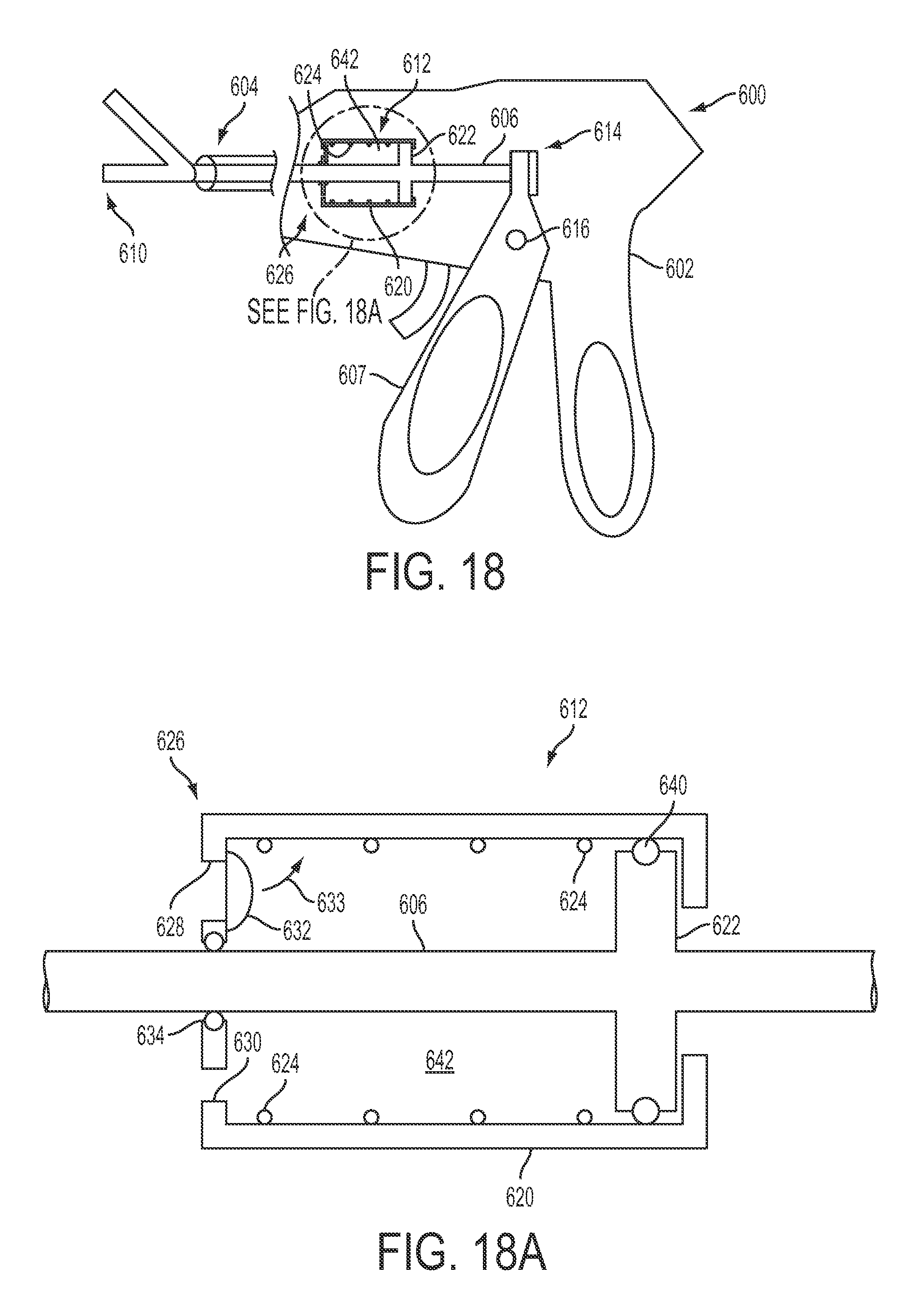
D00015

D00016
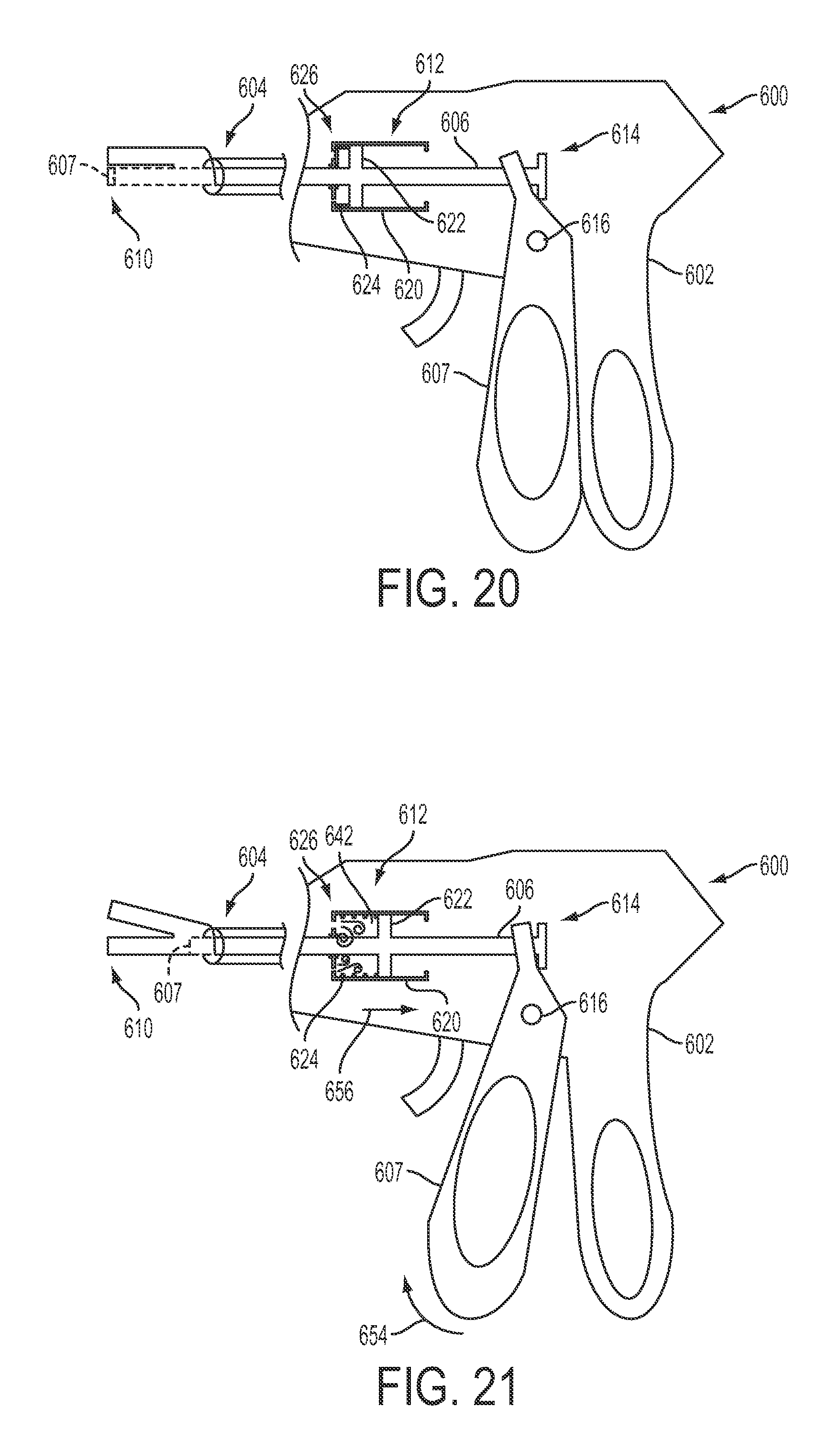
D00017

D00018
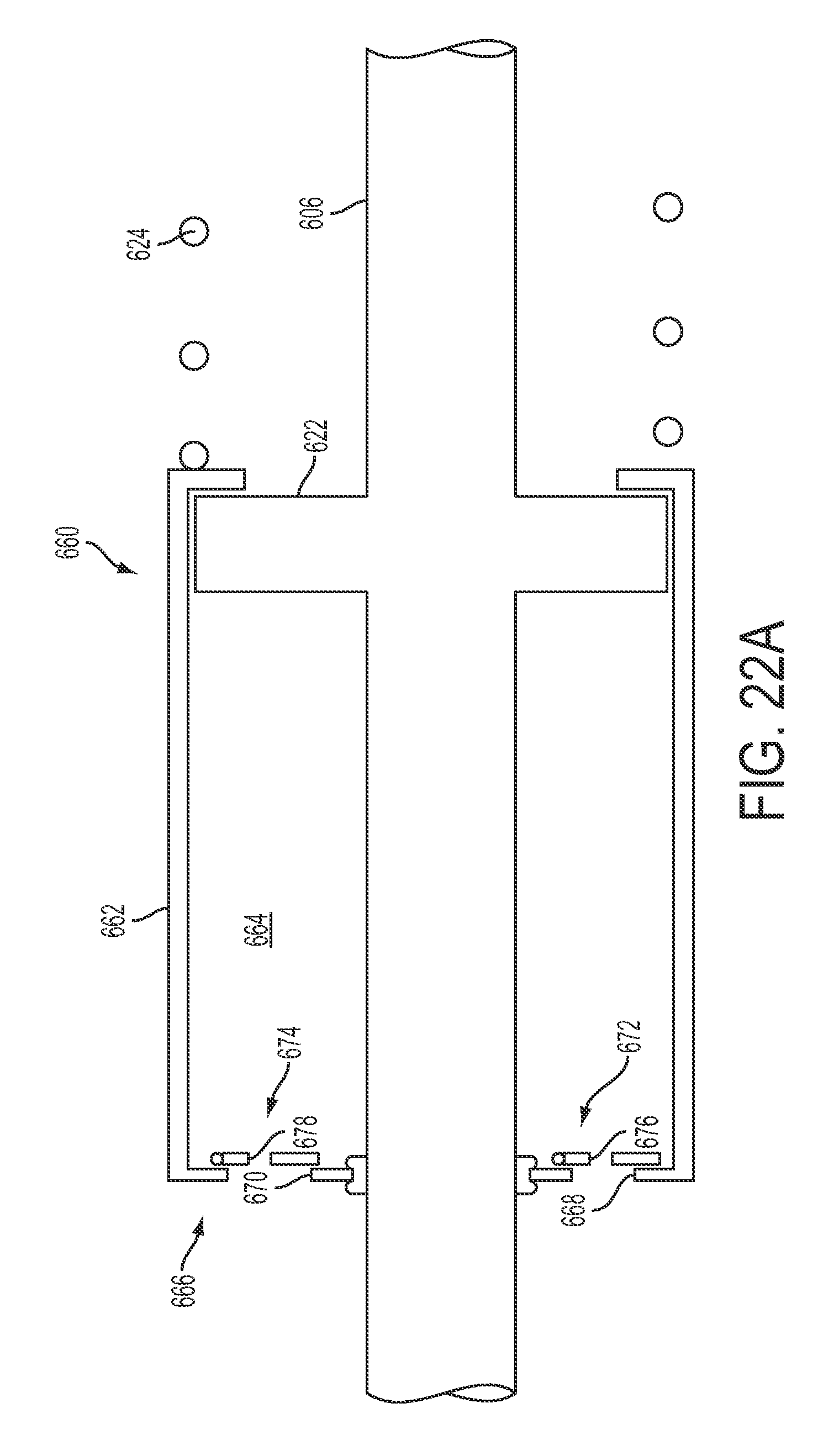
D00019

D00020

D00021

D00022
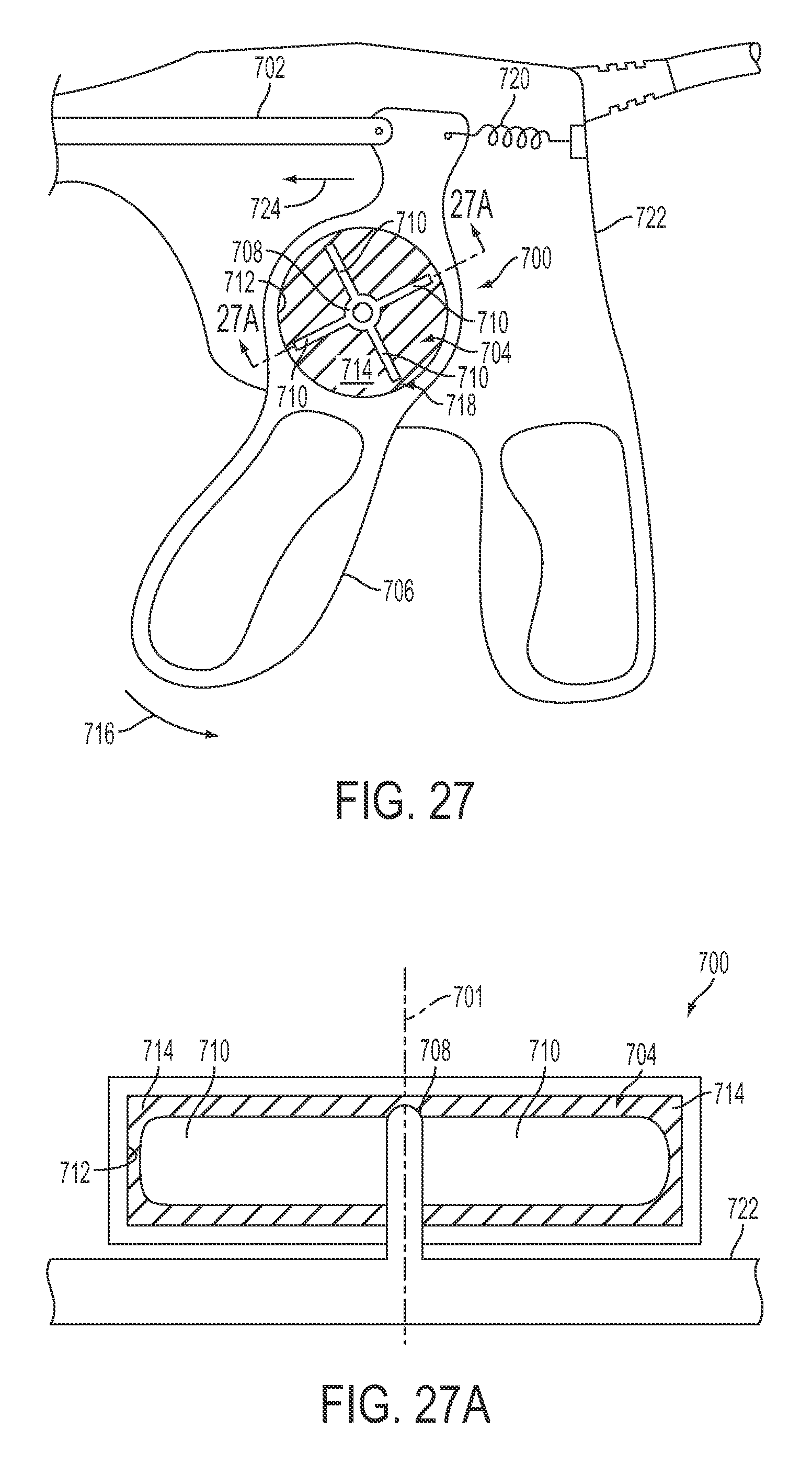
D00023

D00024
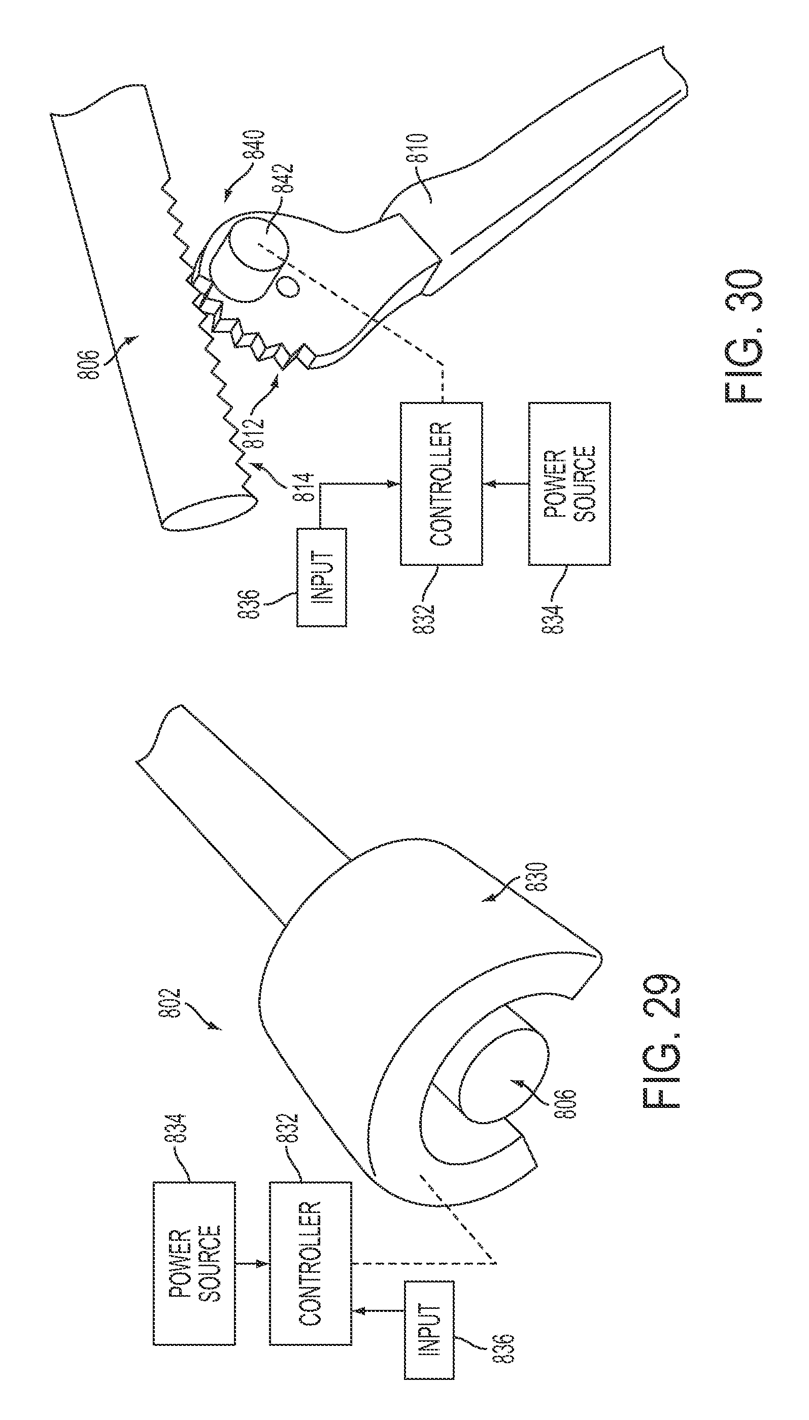
D00025
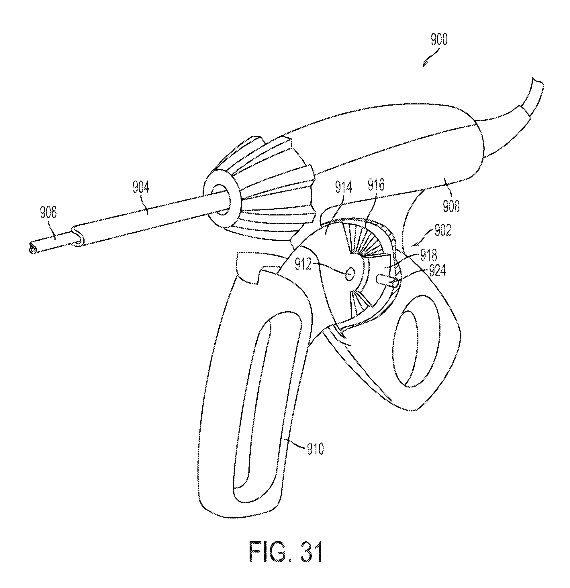
D00026
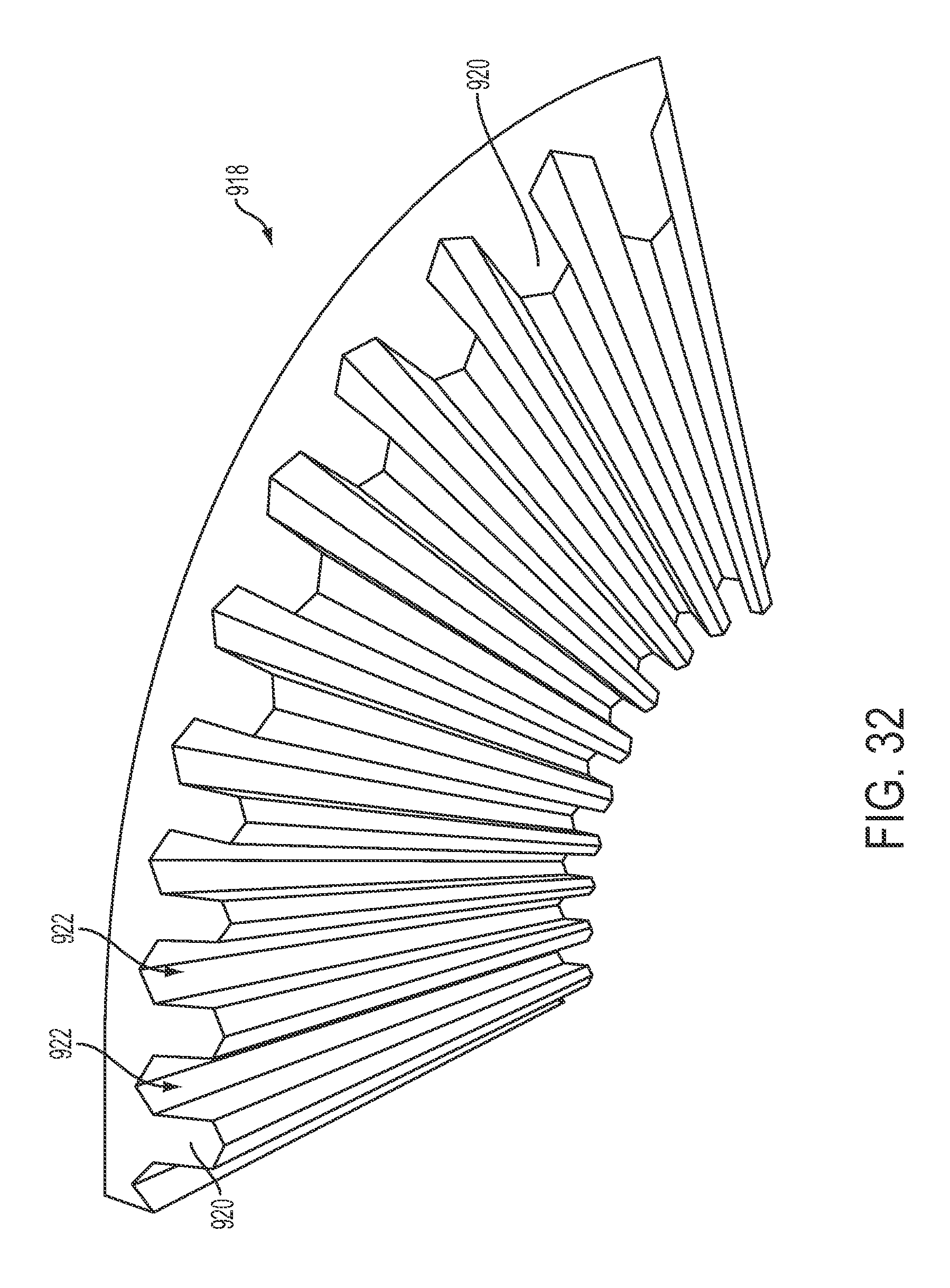
D00027
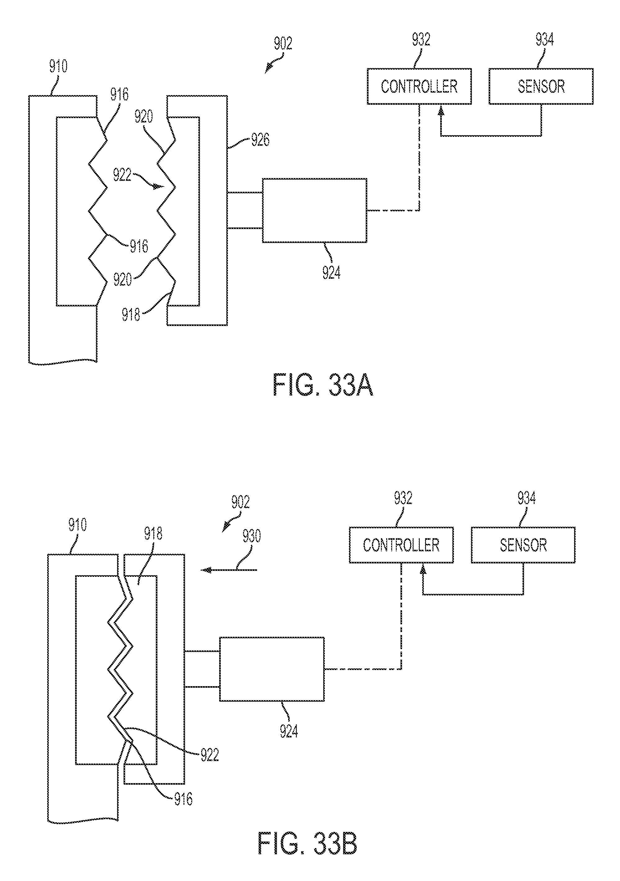
D00028

D00029

D00030
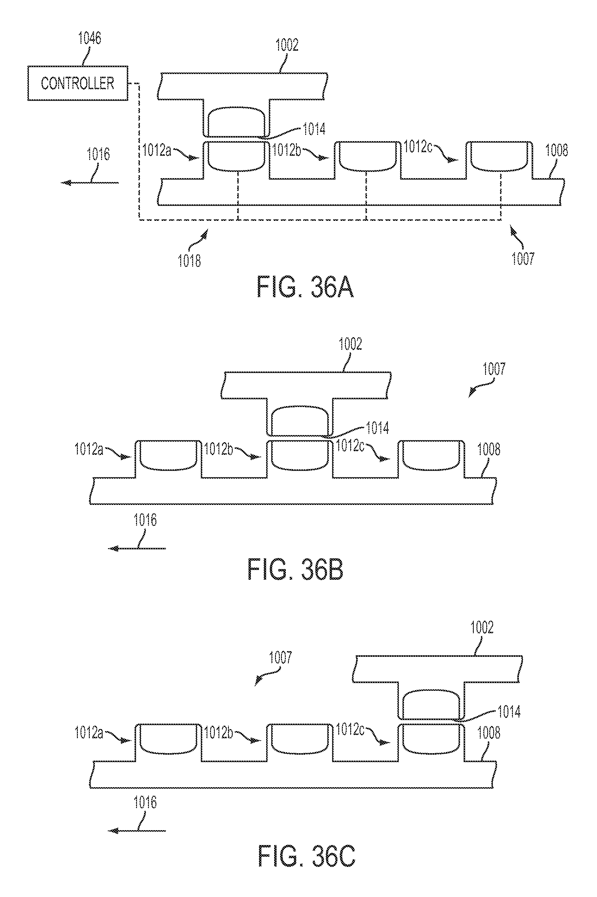
D00031
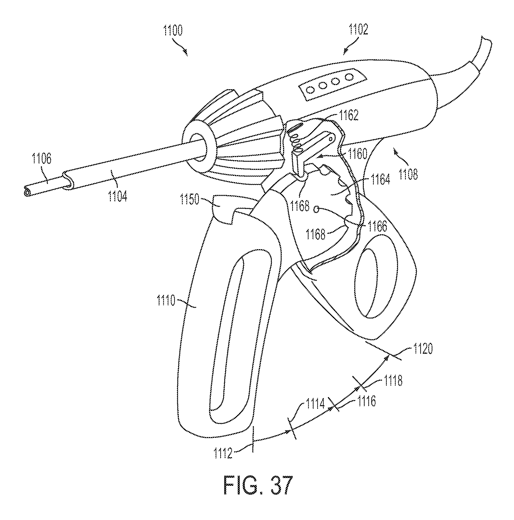
D00032
XML
uspto.report is an independent third-party trademark research tool that is not affiliated, endorsed, or sponsored by the United States Patent and Trademark Office (USPTO) or any other governmental organization. The information provided by uspto.report is based on publicly available data at the time of writing and is intended for informational purposes only.
While we strive to provide accurate and up-to-date information, we do not guarantee the accuracy, completeness, reliability, or suitability of the information displayed on this site. The use of this site is at your own risk. Any reliance you place on such information is therefore strictly at your own risk.
All official trademark data, including owner information, should be verified by visiting the official USPTO website at www.uspto.gov. This site is not intended to replace professional legal advice and should not be used as a substitute for consulting with a legal professional who is knowledgeable about trademark law.