Carton for containers
Holley, Jr. Dec
U.S. patent number 10,518,951 [Application Number 14/973,983] was granted by the patent office on 2019-12-31 for carton for containers. This patent grant is currently assigned to Graphic Packaging International, LLC. The grantee listed for this patent is Graphic Packaging International, Inc. Invention is credited to John Murdick Holley, Jr..


| United States Patent | 10,518,951 |
| Holley, Jr. | December 31, 2019 |
Carton for containers
Abstract
A carrier for holding a plurality of containers. The carrier comprises a plurality of panels extending at least partially around an interior of the carrier. The plurality of panels can comprise at least a front panel and a side panel. A central panel can at least partially divide the interior of the carrier into a front portion and a back portion, and the side panel can extend at least partially between the front panel and the central panel. A handle can comprise a handle feature extending in at least the side panel.
| Inventors: | Holley, Jr.; John Murdick (Lawrenceville, GA) | ||||||||||
|---|---|---|---|---|---|---|---|---|---|---|---|
| Applicant: |
|
||||||||||
| Assignee: | Graphic Packaging International,
LLC (Atlanta, GA) |
||||||||||
| Family ID: | 56128597 | ||||||||||
| Appl. No.: | 14/973,983 | ||||||||||
| Filed: | December 18, 2015 |
Prior Publication Data
| Document Identifier | Publication Date | |
|---|---|---|
| US 20160176594 A1 | Jun 23, 2016 | |
Related U.S. Patent Documents
| Application Number | Filing Date | Patent Number | Issue Date | ||
|---|---|---|---|---|---|
| 62124599 | Dec 23, 2014 | ||||
| Current U.S. Class: | 1/1 |
| Current CPC Class: | B65D 71/0022 (20130101); B65D 2571/00444 (20130101); B65D 2571/00839 (20130101); B65D 2571/00388 (20130101); B65D 2571/00802 (20130101); B65D 2571/0066 (20130101); B65D 2571/00271 (20130101); B65D 2571/00141 (20130101) |
| Current International Class: | B65D 71/58 (20060101) |
References Cited [Referenced By]
U.S. Patent Documents
| 2222211 | November 1940 | Arneson |
| 2225822 | December 1940 | Crook |
| 2227330 | December 1940 | Turner |
| 2331312 | October 1943 | Dorfman |
| 2336857 | December 1943 | Gies et al. |
| 2457308 | December 1948 | Hall et al. |
| 2458281 | January 1949 | Lupton |
| 2460108 | January 1949 | Smith et al. |
| 2525686 | October 1950 | Kowal |
| 2535741 | December 1950 | Lighter |
| 2537615 | January 1951 | Arneson |
| 2660361 | November 1953 | Tyrseck |
| 2689061 | September 1954 | Gray |
| 2721001 | October 1955 | Hasselhoff |
| 2772020 | November 1956 | Kramer |
| 2776072 | January 1957 | Forrer |
| 2783916 | March 1957 | Hodapp |
| 2887245 | May 1959 | Levkoff |
| 2977021 | March 1961 | Shiels, Jr. |
| 2991908 | July 1961 | Conescu |
| 2993619 | July 1961 | Arneson |
| 3029977 | April 1962 | Arneson |
| 3053411 | September 1962 | Struble et al. |
| 3128906 | April 1964 | Forrer |
| 3190487 | June 1965 | Wood |
| 3191800 | June 1965 | Kowal |
| 3194478 | July 1965 | Weiss |
| 3229849 | January 1966 | Spillson |
| 3236414 | February 1966 | Slevin, Jr. |
| 3313466 | April 1967 | Keith |
| 3343742 | September 1967 | Siegler |
| 3352452 | November 1967 | Graser |
| 3373917 | March 1968 | Cox |
| 3432073 | March 1969 | Forrer |
| 3554401 | January 1971 | Wood |
| 3572544 | March 1971 | Forrer |
| 3579653 | May 1971 | Kuhn |
| 3624790 | November 1971 | Stout |
| 3661297 | May 1972 | Wood |
| 3669306 | June 1972 | Forrer |
| 3672539 | June 1972 | Forrer |
| 3709400 | January 1973 | Arneson |
| 3721335 | March 1973 | Grant |
| 3722738 | March 1973 | Wright |
| 3754680 | August 1973 | Wood |
| 3384053 | January 1974 | Stout |
| 3794210 | February 1974 | Stout |
| 3860113 | January 1975 | Helms |
| 3893565 | July 1975 | Rossi et al. |
| 3917059 | November 1975 | Wood |
| 3917060 | November 1975 | Wood |
| 3917061 | November 1975 | Stout |
| 4000813 | January 1977 | Stout |
| 4010847 | March 1977 | Wood et al. |
| 4029205 | June 1977 | Wood |
| 4153158 | May 1979 | Graser et al. |
| 4171046 | October 1979 | Bonczyk |
| 4187944 | February 1980 | Wood |
| 4205748 | June 1980 | Wilson |
| 4217983 | August 1980 | Stout |
| 4243138 | January 1981 | Wilson |
| 4250992 | February 1981 | Gilbert |
| 4253564 | March 1981 | Engdahl, Jr. |
| 4293091 | October 1981 | Gerard |
| 4308950 | January 1982 | Wood |
| 4318470 | March 1982 | Montealegre |
| 4319682 | March 1982 | Wright et al. |
| 4362240 | December 1982 | Elward |
| 4374561 | February 1983 | Stout et al. |
| 4377252 | March 1983 | Schillinger |
| 4406365 | September 1983 | Kulig |
| 4413729 | November 1983 | Wood |
| 4450956 | May 1984 | Wood |
| 4469222 | September 1984 | Graser |
| 4480746 | November 1984 | Wood |
| 4482055 | November 1984 | Boyle |
| 4509640 | April 1985 | Joyce |
| 4544092 | October 1985 | Palmer |
| 4591090 | May 1986 | Collins et al. |
| 4610349 | September 1986 | Schwartz et al. |
| 4722437 | February 1988 | Walsh |
| 4770294 | September 1988 | Graser |
| 4782943 | November 1988 | Blackman |
| 4782944 | November 1988 | Engdahl, Jr. |
| 4792038 | December 1988 | Cooper |
| 4852731 | August 1989 | Cooper |
| 4927009 | May 1990 | Stout |
| 4972944 | November 1990 | McNeill |
| 5029698 | July 1991 | Stout |
| 5040672 | August 1991 | DeMaio et al. |
| 5072876 | December 1991 | Wilson |
| 5123588 | June 1992 | Harris |
| 5161732 | November 1992 | Clein et al. |
| 5167325 | December 1992 | Sykora |
| 5191976 | March 1993 | Stout et al. |
| 5221001 | June 1993 | Eisman |
| 5234103 | August 1993 | Schuster |
| 5246113 | September 1993 | Schuster |
| 5282348 | February 1994 | Dampier et al. |
| 5359830 | November 1994 | Olson et al. |
| 5363954 | November 1994 | Dampier et al. |
| 5400901 | March 1995 | Harrelson |
| 5458234 | October 1995 | Harris |
| 5482203 | January 1996 | Stout |
| 5484053 | January 1996 | Harris |
| 5499712 | March 1996 | Harrelson |
| 5518110 | May 1996 | Harrelson |
| 5531319 | July 1996 | Harrelson |
| 5538130 | July 1996 | Harrelson |
| 5538131 | July 1996 | Harrelson |
| 5547074 | August 1996 | Plaxico et al. |
| 5579625 | December 1996 | Olson et al. |
| 5579904 | December 1996 | Holley, Jr. |
| 5590762 | January 1997 | Harrelson |
| 5593027 | January 1997 | Sutherland |
| 5611425 | March 1997 | Holley, Jr. |
| 5620094 | April 1997 | Naumann |
| 5638956 | June 1997 | Sutherland |
| 5645162 | July 1997 | Harrelson |
| 5649620 | July 1997 | Harrelson |
| 5657864 | August 1997 | Harrelson |
| 5657865 | August 1997 | Harrelson |
| 5680930 | October 1997 | Stone |
| 5682982 | November 1997 | Stonehouse |
| 5682985 | November 1997 | Plaxico et al. |
| 5695051 | December 1997 | Hart |
| 5709298 | January 1998 | Harris |
| D394205 | May 1998 | Bates |
| 5765685 | June 1998 | Roosa |
| 5775487 | July 1998 | Harrelson |
| 5819920 | October 1998 | Sutherland |
| 5855316 | January 1999 | Spivey |
| 5871090 | February 1999 | Doucette et al. |
| 5878877 | March 1999 | Sutherland |
| 5884756 | March 1999 | Holley, Jr. et al. |
| 5941377 | August 1999 | Haft et al. |
| 5947273 | September 1999 | Dalrymple et al. |
| 5979645 | November 1999 | Holley |
| 6003665 | December 1999 | Stout |
| 6041920 | March 2000 | Hart et al. |
| 6102197 | August 2000 | Negelen |
| 6112977 | September 2000 | Sutherland et al. |
| 6131729 | October 2000 | Eckermann et al. |
| 6155962 | December 2000 | Dalrymple et al. |
| 6168013 | January 2001 | Gomes |
| 6230881 | May 2001 | Collura |
| 6247585 | June 2001 | Holley, Jr. |
| 6315111 | November 2001 | Sutherland |
| 6321906 | November 2001 | Wein |
| 6341689 | January 2002 | Jones |
| 6371287 | April 2002 | Jones et al. |
| 6571941 | June 2003 | Holley, Jr. |
| 6695137 | February 2004 | Jones et al. |
| 6736260 | May 2004 | Gomes et al. |
| 6802802 | October 2004 | Woog |
| 6814228 | November 2004 | Sutherland |
| 6938756 | September 2005 | Schuster |
| 7011209 | March 2006 | Sutherland et al. |
| 7025197 | April 2006 | Sutherland |
| 7070045 | July 2006 | Theelen |
| 7128206 | October 2006 | Kohler |
| 7134547 | November 2006 | Aclair |
| 7207934 | April 2007 | Schuster |
| 7374038 | May 2008 | Smalley |
| 7448492 | November 2008 | Sutherland |
| 7472791 | January 2009 | Spivey, Sr. |
| 7552820 | June 2009 | Kohler |
| 7578385 | August 2009 | Holley |
| 7604116 | October 2009 | Schuster |
| 7644817 | January 2010 | Sutherland |
| 7677387 | March 2010 | Brand et al. |
| 7753195 | July 2010 | Cuomo |
| 7762395 | July 2010 | Sutherland et al. |
| 7762397 | July 2010 | Coltri-Johnson et al. |
| 7793780 | September 2010 | Smalley |
| 8020695 | September 2011 | Brand |
| 8297437 | October 2012 | Smalley et al. |
| 8453832 | June 2013 | Skolik et al. |
| 8770397 | July 2014 | Holley, Jr. |
| 9061810 | June 2015 | Brand |
| 2002/0077236 | June 2002 | Chalendar et al. |
| 2002/0117407 | August 2002 | Holley |
| 2003/0111363 | June 2003 | Theelen |
| 2003/0159950 | August 2003 | Jones et al. |
| 2003/0213705 | November 2003 | Woog |
| 2004/0026269 | February 2004 | Cuomo |
| 2004/0050722 | March 2004 | Schuster |
| 2004/0094435 | May 2004 | Auclair et al. |
| 2004/0104134 | June 2004 | Skolik et al. |
| 2005/0211577 | September 2005 | Bakx |
| 2005/0218014 | October 2005 | Schuster |
| 2005/0230273 | October 2005 | Kohler |
| 2006/0091024 | May 2006 | Cuomo |
| 2006/0148629 | July 2006 | Cuomo |
| 2006/0157545 | July 2006 | Auclair |
| 2006/0231440 | October 2006 | Holley, Jr. |
| 2007/0000980 | January 2007 | Oliveira |
| 2007/0017839 | January 2007 | Sutherland |
| 2007/0029211 | February 2007 | Cuomo |
| 2007/0029212 | February 2007 | Smalley |
| 2007/0151873 | July 2007 | Schuster |
| 2008/0041735 | February 2008 | Cuomo |
| 2008/0210581 | September 2008 | Brand |
| 2009/0008273 | January 2009 | Smalley |
| 2010/0006458 | January 2010 | Wilkins et al. |
| 2010/0072086 | March 2010 | Smalley |
| 2010/0320098 | December 2010 | Brand |
| 2011/0127318 | June 2011 | Philips |
| 2015/0321816 | November 2015 | Holley |
| 9004439 | Jun 1990 | DE | |||
| 1 319 607 | Jun 2003 | EP | |||
| 1 852 359 | Nov 2007 | EP | |||
| 2 102 073 | Sep 2010 | EP | |||
| 2 825 074 | Nov 2002 | FR | |||
| 926874 | May 1963 | GB | |||
| WO 97/05026 | Feb 1997 | WO | |||
| WO 99/01356 | Jan 1999 | WO | |||
| WO 2006/020525 | Feb 2006 | WO | |||
| WO 2006/113824 | Oct 2006 | WO | |||
| WO 2008/089124 | Jul 2008 | WO | |||
Other References
|
International Search Report and Written Opinion for PCT/US2015/066591 dated Apr. 12, 2016. cited by applicant. |
Primary Examiner: Reynolds; Steven A.
Assistant Examiner: Pagan; Javier A
Attorney, Agent or Firm: Womble Bond Dickinson (US) LLP
Parent Case Text
CROSS-REFERENCE TO RELATED APPLICATIONS
This application claims the benefit of U.S. Provisional Patent Application No. 62/124,599, filed on Dec. 23, 2014.
INCORPORATION BY REFERENCE
The disclosure of U.S. Provisional Patent Application No. 62/124,599, which was filed on Dec. 23, 2014, is hereby incorporated by reference for all purposes as if presented herein in its entirety.
Claims
What is claimed is:
1. A carrier for holding a plurality of containers, the carrier comprising: a plurality of panels extending at least partially around an interior of the carrier, the plurality of panels comprising at least a front panel and a side panel; a central panel at least partially dividing the interior of the carrier into a front portion and a back portion, the side panel extending at least partially between the front panel and the central panel; a handle comprising a handle feature extending in at least the side panel; and a reinforcing structure, the reinforcing structure at least partially overlapping at least one panel of the plurality of panels, the reinforcing structure comprises a front reinforcing panel foldably connected to a top marginal portion of the front panel and positioned in at least partial face-to-face contact with a top portion of the top panel, a side reinforcing panel foldably connected to a top marginal portion of the side panel and positioned in at least partial face-to-face contact with a top portion of the side panel, and a central reinforcing panel foldably connected to a top marginal portion of the central panel and positioned in at least partial face-to-face contact with a top portion of the central panel, such that the reinforcing structure reinforces a top portion of the carrier.
2. The carrier of claim 1, wherein the handle feature comprises a handle opening extending in the side panel.
3. The carrier of claim 1, wherein the handle feature comprises a handle flap foldably connected to the side panel.
4. The carrier of claim 3, wherein the side panel is foldably connected to the central panel along a first fold line, the handle flap is foldably connected to the side panel along a second fold line, and the second fold line extends from the first fold line.
5. The carrier of claim 4, wherein the handle further comprises a handle opening extending in the side panel adjacent the central panel and the handle flap.
6. The carrier of claim 1, further comprising a central flap being at least partially overlapped with the central panel, wherein the side panel is foldably connected to the front panel and the central flap.
7. The carrier of claim 1, wherein the side panel is foldably connected to the central panel and to the front panel.
8. The carrier of claim 7, wherein the side panel is a first side panel, the plurality of panels further comprises a second side panel foldably connected to the front panel, the second side panel is foldably connected to a central flap, and the central flap is at least partially overlapped with the central panel.
9. The carrier of claim 8, wherein the handle is a first handle and the handle feature is a first handle feature, the carrier further comprising a second handle comprising a second handle feature extending in at least the second side panel.
10. The carrier of claim 9, wherein the first handle feature comprises a first handle opening in the first side panel, and the second handle feature comprises a second handle opening in the second side panel.
11. The carrier of claim 9, wherein the first handle feature comprises a first handle flap foldably connected to the first side panel, and the second handle feature comprises a second handle flap foldably connected to the second side panel.
12. The carrier of claim 8, wherein the side reinforcing panel is a first side reinforcing panel at least partially overlapping the first side panel, and the reinforcing structure further comprises a second side reinforcing panel at least partially overlapping the second side panel.
13. The carrier of claim 12, wherein the handle is a first handle comprising a first handle opening in the first side panel and a second handle opening in the first side reinforcing panel, the second handle opening being generally aligned with the first handle opening, the carrier further comprising a second handle comprising a third handle opening in the second side panel and a fourth handle opening in the second side reinforcing panel, the fourth handle opening being generally aligned with the third handle opening.
14. The carrier of claim 1, wherein front panel is foldably connected to a bottom panel, the plurality of panels further comprises a back panel, and the back panel is foldably connected to the bottom panel.
15. The carrier of claim 1, wherein the side panel is a front side panel, and the plurality of panels further comprises at least a back panel and a back side panel.
16. The carrier of claim 15, wherein the handle feature is a first handle feature, and the handle further comprises a second handle feature extending the back side panel.
17. The carrier of claim 16, wherein the first handle feature comprises a first handle opening in the front side panel, and the second handle feature comprises a second handle opening in the back side panel.
18. The carrier of claim 17, wherein the reinforcing structure is a front reinforcing structure and the carrier further comprises a back reinforcing structure, the side reinforcing panel is a front side reinforcing panel of the front reinforcing structure and at least partially overlaps the front side panel, the back reinforcing structure comprising at least a back side reinforcing panel at least partially overlapping the back side panel, and the handle further comprises a third handle opening in the front side reinforcing panel and a fourth handle opening in the back side reinforcing panel, the third handle opening and the fourth handle opening being generally aligned with the respective first handle opening and second handle opening.
19. The carrier of claim 16, wherein the first handle feature comprises a first handle flap foldably connected to the front side panel, and the second handle feature comprises a second handle flap foldably connected to the back side panel.
20. The carrier of claim 1, wherein the side panel is foldably connected to the front panel and the central panel, and the side reinforcing panel is foldably connected to the front reinforcing panel and the central reinforcing panel.
21. The carrier of claim 1, wherein the reinforcing structure is foldably connected to the at least one panel.
22. The carrier of claim 1, wherein the handle further comprises a handle opening in the side reinforcing panel, and the handle opening is at least partially aligned with the handle feature in the side panel.
23. The carrier of claim 22, wherein the side reinforcing panel is foldably connected to the side panel.
24. The carrier of claim 1, further comprising a divider flap foldably connected to the central panel and extending from the central panel to the front panel, wherein the divider flap comprises an attachment flap engaging the front panel.
25. The carrier of claim 1, wherein at least one panel of the plurality of panels comprises a height, and the height is substantially equal to or greater than an article height of at least one article of the plurality of articles.
26. The carrier of claim 1, wherein at least one of the front reinforcing panel, the side reinforcing panel, and the central reinforcing panel is foldably connected to at least one of the respective top marginal portion of the front panel, the top marginal portion of the side panel, and the top marginal portion of the central panel at a respective longitudinal fold line.
27. A blank for forming a carrier for holding a plurality of containers, the blank comprising: a plurality of panels comprising at least a front panel and a side panel; a central panel for at least partially dividing the carrier formed from the blank into a front portion and a back portion, the side panel being for extending at least partially between the front panel and the central panel when the carrier is formed from the blank; a handle comprising a handle feature extending in at least the side panel; and a reinforcing structure for reinforcing a top portion of the carrier formed from the blank, the reinforcing structure being for at least partially overlapping at least one panel of the plurality of panels in the carrier formed from the blank, the reinforcing structure comprises a front reinforcing panel foldably connected to a top marginal portion of the front panel and for being positioned in at least partial face-to-face contact with a top portion of the front panel in the carrier formed from the blank, a side reinforcing panel foldably connected to a top marginal portion of the side panel and for being positioned in at least partial face-to-face contact with a top portion of the side panel in the carrier formed from the blank, and a central reinforcing panel foldably connected to a top marginal portion of the side panel and for being positioned in at least partial face-to-face contact with a top portion of the central panel in the carrier formed from the blank.
28. The blank of claim 27, wherein the handle feature comprises a handle opening extending in the side panel.
29. The blank of claim 27, wherein the handle feature comprises a handle flap foldably connected to the side panel.
30. The blank of claim 27, wherein the side panel is foldably connected to the central panel and to the front panel.
31. The blank of claim 30, wherein the side panel is a first side panel, the plurality of panels further comprises a second side panel foldably connected to the front panel, the second side panel is foldably connected to a central flap, and the central flap is for being at least partially overlapped with the central panel when the carrier is formed from the blank.
32. The blank of claim 31, wherein the handle is a first handle and the handle feature is a first handle feature, the carrier further comprising a second handle comprising a second handle feature extending in at least the second side panel.
33. The blank of claim 27, wherein front panel is foldably connected to a bottom panel, the plurality of panels further comprises a back panel, and the back panel is foldably connected to the bottom panel.
34. The blank of claim 27, wherein the side panel is a front side panel, and the plurality of panels further comprises at least a back panel and a back side panel.
35. The blank of claim 34, wherein the handle feature is a first handle feature, and the handle further comprises a second handle feature extending the back side panel.
36. The blank of claim 27, wherein the side panel is foldably connected to the front panel and the central panel, and the side reinforcing panel is foldably connected to the front reinforcing panel and the central reinforcing panel.
37. The blank of claim 27, wherein the reinforcing structure is foldably connected to the at least one panel.
38. The blank of claim 27, wherein the handle further comprises a handle opening in the side reinforcing panel, and the handle opening is for being at least partially aligned with the handle feature in the side panel when the carrier is formed from the blank.
39. The blank of claim 38, wherein the side reinforcing panel is foldably connected to the side panel.
40. The blank of claim 27, further comprising a divider flap foldably connected to the central panel and an attachment flap foldably connected to the divider flap, wherein the divider flap is for extending from the central panel to the front panel and the attachment flap is for engaging the front panel when the carrier is formed from the blank.
41. A method of forming a carrier for holding a plurality of containers, the method comprising: obtaining a blank comprising a plurality of panels, a central panel, a handle feature, and a reinforcing structure, the plurality of panels comprising at least a front panel and a side panel, the handle feature extending in at least the side panel, and the reinforcing structure comprising a front reinforcing panel foldably connected to a top marginal portion of the front panel, a side reinforcing panel foldably connected to a top marginal portion of the side panel, and a central reinforcing panel foldably connected to a top marginal portion of the central panel; and forming an interior of the carrier by positioning the panels of the plurality of panels to extend at least partially around the interior of the carrier, positioning the central panel to at least partially divide the interior of the carrier into a front portion and a back portion, the side panel extending at least partially between the front panel and the central panel; reinforcing a top portion of the carrier by positioning the front reinforcing panel in at least partial face-to-face contact with a top portion of the front panel, positioning the side reinforcing panel in at least partial face-to-face contact with a top portion of the side panel to at least partially overlap the side panel, and positioning the central reinforcing panel in at least partial face-to-face contact with a top portion of the central panel; wherein the handle feature at least partially forms a handle in the carrier.
42. The method of claim 41, wherein the side panel is a first side panel, the handle is a first handle, and the handle feature is a first handle feature, the plurality of panels further comprises a second side panel, the positioning the panels of the plurality of panels comprising disposing the second side panel generally opposite to the first side panel, and the blank further comprises a second handle comprising a second handle feature extending in the second side panel.
43. The method of claim 41, wherein the front panel is foldably connected to a bottom panel, the plurality of panels further comprises a back panel, the back panel is foldably connected to the bottom panel, and the method further comprises positioning the front panel and the back panel respectively opposite to the central panel so that the bottom panel extends from the front panel to the back panel and the central panel extends adjacent the bottom panel.
44. The method of claim 41, wherein the side panel is a front side panel and the handle feature is a first handle feature, the plurality of panels further comprises a back panel and a back side panel, the back side panel extends at least partially between the central panel and the back panel, and the handle further comprises a second handle feature extending in the back side panel.
45. The method of claim 41, wherein the reinforcing structure is foldably connected to the at least one panel.
46. The method of claim 41, wherein the handle further comprises a handle opening extending in the side reinforcing panel, and positioning the side reinforcing panel comprises disposing the handle opening to be generally aligned with the handle feature.
Description
BACKGROUND OF THE DISCLOSURE
The present disclosure generally relates to carriers or cartons for holding and displaying containers. More specifically, the present disclosure relates to basket-style carriers.
SUMMARY OF THE DISCLOSURE
In general, one aspect of the disclosure is directed to a carrier for holding a plurality of containers. The carrier comprises a plurality of panels extending at least partially around an interior of the carrier. The plurality of panels can comprise at least a front panel and a side panel. A central panel can at least partially divide the interior of the carrier into a front portion and a back portion, and the side panel can extend at least partially between the front panel and the central panel. A handle can comprise a handle feature extending in at least the side panel.
In another aspect, the disclosure is generally directed to a blank for forming a carrier for holding a plurality of containers. The blank comprises a plurality of panels comprising at least a front panel and a side panel. A central panel can be for at least partially dividing the carrier formed from the blank into a front portion and a back portion. The side panel can be for extending at least partially between the front panel and the central panel when the carrier is formed from the blank. A handle can comprise a handle feature extending in at least the side panel.
In another aspect, the disclosure is generally directed to a method of forming a carrier for containing a plurality of containers. The method comprises obtaining a blank comprising a plurality of panels, a central panel, and a handle feature. The plurality of panels can comprise at least a front panel and a side panel. The handle feature can extend in at least the side panel. The method further can comprise forming an interior of the carrier by positioning the panels of the plurality of panels to extend at least partially around the interior of the carrier and positioning the central panel to at least partially divide the interior of the carrier into a front portion and a back portion. The side panel can extend at least partially between the front panel and the central panel. The handle feature can at least partially form a handle in the carrier.
Those skilled in the art will appreciate the above stated advantages and other advantages and benefits of various additional embodiments reading the following detailed description of the embodiments with reference to the below-listed drawing figures.
According to common practice, the various features of the drawings discussed below are not necessarily drawn to scale. Dimensions of various features and elements in the drawings may be expanded or reduced to more clearly illustrate the embodiments of the disclosure.
BRIEF DESCRIPTION OF THE DRAWINGS
FIG. 1 is an exterior plan view of a blank used to form a carrier according to an exemplary embodiment of the disclosure.
FIGS. 2-4 are views showing folding of the blank of FIG. 1 to form the carrier according to the exemplary embodiment of the disclosure.
FIG. 5 is a plan view of the carrier formed from the blank of FIG. 1 in a flattened configuration.
FIG. 6 is an exterior perspective view of the assembled carrier according to the exemplary embodiment of the disclosure.
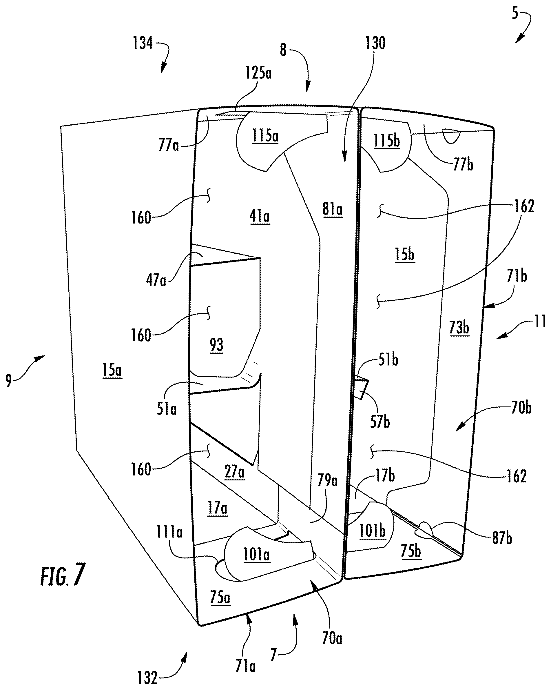
FIG. 7 is a top perspective view of the carrier of FIG. 6.
FIG. 8 is an exterior perspective view of a package including the assembled carrier of FIG. 6 with containers received therein.
Corresponding parts are designated by corresponding reference numbers throughout the drawings.
DETAILED DESCRIPTION OF THE EXEMPLARY EMBODIMENT
The present disclosure generally relates to carriers, packages, constructs, sleeves, cartons, or the like, for holding and displaying containers such as jars, bottles, cans, etc. The containers can be used for packaging food and beverage products, for example. The containers can be made from materials suitable in composition for packaging the particular food or beverage item, and the materials include, but are not limited to, plastics such as PET, LDPE, LLDPE, HDPE, PP, PS, PVC, EVOH, and Nylon; and the like; aluminum and/or other metals; glass; or any combination thereof.
Carriers according to the present disclosure can accommodate containers of numerous different shapes. For the purpose of illustration and not for the purpose of limiting the scope of the disclosure, the following detailed description describes beverage containers (e.g., glass and/or aluminum bottles or plastic containers) at least partially disposed within the carrier embodiments. In this specification, the terms "inner," "interior," "outer," "exterior," "lower," "bottom," "upper," "top," "front," "forward," "back," and "rearward" indicate orientations determined in relation to fully erected carriers.
FIG. 1 is a plan view of an exterior side 1 of the blank 3 used to form a package or basket-style carrier 5 (FIGS. 6-8), in accordance with an exemplary embodiment of the present disclosure. As shown in FIG. 8, the carrier 5 is sized to contain six containers C, three containers being contained in a front portion 9 of the carrier and three containers being contained in a back portion 11 of the carrier. The carrier can be sized and shaped to hold containers of a different or same quantity in more than one layer and/or in different row/column arrangements (e.g., 1.times.6, 3.times.4, 2.times.6.times.2, 3.times.5, 4.times.5, 2.times.9, 2.times.6, 4.times.4, etc.). In the illustrated embodiment, the carrier 5 includes handles 7, 8 (FIGS. 8-10). As will be discussed below in more detail, the handles 7, 8, are formed from various features in the blank 3.
The carrier blank 3 has a longitudinal axis L1 and a lateral or transverse axis L2. The carrier blank 3 has a front portion 9, a back portion 11, a bottom panel 12 foldably connected to the front portion and the back portion. In the illustrated embodiment, the front portion 9 and back portion 11 are for being folded about a lateral centerline CL (FIG. 1) when the carrier blank 3 is formed into the carrier 5. In one embodiment, a lateral intermediate fold line 14 in the bottom panel 12 can extend along the centerline CL. As discussed in more detail below, the carrier blank 3 is formed into the carrier 5 by folding the carrier blank about the centerline CL (e.g., the intermediate fold line 14) so that the front portion 9 and the back portion 11 are generally overlapped.
In the illustrated embodiment, the front portion 9, comprises a front panel 15a foldably connected to a first side panel 17a and a second side panel 19a. A front central flap 27a is foldably connected to the first side panel 17a at a longitudinal fold line 29a. Longitudinal fold lines 31a, 33a foldably connect the respective first and second side panel 17a, 19a to the front panel 15a. A lateral fold line 35a connects the bottom panel 12 to the front panel 15a.
As shown in FIG. 1, the front portion 9 includes a front central panel 41a foldably connected to the second side panel 19a at a longitudinal fold line 43a. A first divider flap 47a is foldably connected to the front central panel 41a along a longitudinal fold line 49a. A second divider flap 51a is foldably connected to the front central panel 41a at two longitudinal fold lines 53a that are spaced apart by a portion of the first divider flap 47a. Each of the divider flaps 47a, 51a includes a respective attachment flap 55a, 57a. The attachment flaps 55a, 57a are foldably connected to the respective divider flaps 47a, 51a at respective longitudinal fold lines 59a, 61a. A generally U-shaped cut 60a extends between the fold lines 59a, and a generally U-shaped cut 62a extends between the fold lines 61a. The first divider flap 47a and the attachment flap 55a are at least partially defined by a tear or cut line 63a, the cut 60a, and the fold lines 49a, 59a. The second divider flap 51a is at least partially defined by the cut line 63a, the cut 62a, the fold lines 53a, 61a, and a tear or cut line 65a that extends from a longitudinal edge of the blank 3 to the fold lines 53a. The central panel 41a, any of the divider flaps 47a, 51a, and/or any of the attachment flaps 55a, 57a could be omitted or could be otherwise shaped, arranged, positioned, and/or configured without departing from the disclosure.
As shown in FIG. 1, the front portion 9 can include a front reinforcing structure 70a foldably connected to the front panel 15a, the front side panels 17a, 19a, the front central flap 27a, and the front central panel 41a along a lateral fold line 71a. The front reinforcing structure 70a can include a front reinforcing panel 73a, side reinforcing panels 75a, 77a, and central reinforcing panels 79a, 81a. The front reinforcing panel 73a can be foldably connected to the side reinforcing panels 75a, 77a along respective longitudinal fold lines 83a, 85a and separated from the side reinforcing panels 75a, 77a, along respective slots or openings 87a. The side reinforcing panels 75a, 77a are foldably connected to the respective central reinforcing panels 79a, 81a along respective fold lines or fold areas 89a, 91a. In the illustrated embodiment, the fold areas 89a, 91a each can include two spaced, parallel fold lines (which can be interrupted by respective handle features as described in more detail below). As shown in FIG. 1, the front reinforcing panel 73a, the side reinforcing panels 75a, 77a, and the central reinforcing panels 79a, 81a are foldably connected to the respective front panel 15a, side panels 17a, 19a, front central flap 27a, and front central panel 41a along the lateral fold line 71a. In one embodiment, the slots 87a and/or the fold areas 89a, 91a can help with folding of the panels when forming the carrier 5 while the reinforcing panels 73a, 75a, 77a, 79a, 81a overlap the respective front panel 15a, side panels 17a, 19a, central flap 27a, and central panel 41a and the fold lines 83a, 85a and fold areas 89a, 91a overlap the respective fold lines 31a, 33a, 29a, 43a. The front reinforcing structure 70a could be omitted or could be otherwise shaped, arranged, positioned, and/or configured without departing from the disclosure.
In the illustrated embodiment, the features of the back portion 11 of the blank 3 include a back panel 15b, a first side panel 17b, and a second side panel 19b, that are generally a mirror-image of the corresponding panel or flap of the front portion 9. A back central flap 27b is also similarly configured to (e.g., generally a mirror image of) the front central flap 27a, and a back central panel 41b is similarly configured to (e.g., generally a mirror image of) the front central panel 41a. Additionally, back divider flaps 47b, 51b and attachment flaps 55b, 57b are similarly configured to (e.g., generally a mirror image of) the front divider flaps 47a, 51a and attachment flaps 55a, 57a. Further, a back reinforcing structure 70b, including reinforcing panels 73b, 75b, 77b, 79b, 81b, is similarly configured to (e.g., generally a mirror image of) the front reinforcing structure 70a, including respective reinforcing panels 73a, 75a, 77a, 79a, 81a. Alternatively, one or more of the features of the back portion 11 could be different than the respective feature(s) of the front portion 9. Corresponding components (e.g., panels, flaps, fold lines, cuts, etc.) have been designated by corresponding reference numbers that differ by the "a" or "b" suffix, with the "a" components corresponding to the front portion 9 and the "b" components corresponding to the back portion 11 of the blank 3.
As shown in FIG. 1, the front panel 15a is foldably connected to the bottom panel 12 along the lateral fold line 35a, and the back panel 15b is foldably connected to the bottom panel 12 along a lateral fold line 35b. An intermediate panel 93 can be foldably connected to the back central panel 41b along a fold line 95 and can be separable from the front central panel 41a and the divider flap 51a along a cut or tear line 96. Alternatively, the intermediate panel 93 could be spaced from the front central panel 41a by a cutout or opening, for example. In the illustrated embodiment, the intermediate panel is separable from the divider flap 51b along a tear or cut line 97. The front portion 9 is generally spaced from the back portion by the bottom panel 12, and a cutout or opening 99 can be formed between the front central panel 41a, the front side panel 19a, the bottom panel 12, the intermediate panel 93, the back central panel 41b, and the back side panel 19b. The blank 3 could be otherwise shaped, arranged, positioned, and/or configured without departing from the disclosure.
In the illustrated embodiment, the features that form the handles 7, 8 can include handle features formed in the front side panels 17a, 19a, back side panels 17b, 19b, and side reinforcing panels 75a, 77a, 75b, 77b. As shown in FIG. 1, features 100a for forming the handle 7 can include a first handle flap 101a foldably connected to the first side panel 17a along a lateral fold line 103a adjacent an opening 105a. The first handle flap 101a can be separable from the first side panel 17a along a curved tear or cut line 107a and can be separable from the front central flap 27a along a longitudinal tear or cut line 109a. As shown in FIG. 1, the opening 105a can interrupt the fold line 29a and can extend along an edge of the central flap 27a and/or can extend into the central flap 27a. In the illustrated embodiment, a handle opening 111a can be formed in the side reinforcing panel 75a adjacent the central reinforcing panel 79a so that the opening 111a interrupts the fold area 89a. As shown in FIG. 1, features 100b for forming the handle 7 can include a corresponding second handle flap 101b foldably connected to the first side panel 17b along a lateral fold line 103b adjacent an opening 105b. The second handle flap 101b can be separable from the first side panel 17b along a curved tear or cut line 107b and can be separable from the back central flap 27b along a longitudinal tear or cut line 109b. As shown in FIG. 1, the opening 105b can interrupt the fold line 29b and can extend along an edge of the central flap 27b and/or can extend into the central flap 27b. A handle opening 111b can be formed in the side reinforcing panel 75b adjacent the central reinforcing panel 79b so that the opening 111b interrupts the fold area 89b. In one embodiment, the handle features 100b generally can be similarly configured to (e.g., generally a mirror image of) the handle features 100a. Any of the handle features 100a, 100b could be omitted or could be otherwise shaped, arranged, positioned, and/or configured without departing from the disclosure. For example, the handle 7 could include one or more handle flaps could be foldably connected to one or both of the side reinforcing panels 75a, 75b alternatively or in addition to the handle flaps 101a, 101b.
Similarly, in the illustrated embodiment, handle features 114a for forming the handle 8 can include a first handle flap 115a foldably connected to the second side panel 19a along a lateral fold line 117a adjacent an opening 119a. The first handle flap 115a can be separable from the second side panel 19a along a curved tear or cut line 121a and from the front central panel 41a along a longitudinal tear or cut line 123a. As shown in FIG. 1, the opening 119a can interrupt the fold line 43a and can extend along an edge of the central panel 41a and/or can extend into the central panel 41a. In the illustrated embodiment, a handle opening 125a can be formed in the side reinforcing panel 77a adjacent the central reinforcing panel 81a so that the opening 125a interrupts the fold area 91a. As shown in FIG. 1, features 114b for forming the handle 8 can include a corresponding second handle flap 115b foldably connected to the second side panel 19b along a lateral fold line 117b adjacent an opening 119b. The second handle flap 115b can be separable from the second side panel 19b along a curved tear or cut line 121b and from the back central panel 41b along a longitudinal tear or cut line 123b. As shown in FIG. 1, the opening 119b can interrupt the fold line 43b and can extend along an edge of the central panel 41b and/or can extend into the central panel 41b. A handle opening 125b can be formed in the side reinforcing panel 77b adjacent the central reinforcing panel 81b so that the opening 125b interrupts the fold area 91b. In one embodiment, the handle features 114b generally can be similarly configured to (e.g., generally a mirror image of) the handle features 114a. Any of the handle features 114a, 114b could be omitted or could be otherwise shaped, arranged, positioned, and/or configured without departing from the disclosure. For example, the handle 8 could include one or more handle flaps could be foldably connected to one or both of the side reinforcing panels 77a, 77b alternatively or in addition to the handle flaps 115a, 115b.
As shown in FIG. 1, in the front reinforcing structure 70a, the front reinforcing panel 73a and the central reinforcing panel 81a have portions that are narrower than the side reinforcing panels 75a, 77a and the central reinforcing panel 79a (e.g., in the longitudinal direction L1). The front reinforcing panel 73a and the central reinforcing panel 81a can be tapered adjacent to the wider side reinforcing panels 75a, 77a and central reinforcing panel 79a. Accordingly, the front reinforcing structure 70a can extend around the handle features 100a, 114a while the narrower front reinforcing panel 73a and central reinforcing panel 81a can help reduce the amount of blank material needed. The back reinforcing structure 70b is similarly configured in the illustrated embodiment. In an alternative embodiment, the front reinforcing structure 70a and/or the back reinforcing structure 70b could have a consistent width (e.g., the longitudinal distance between the fold line 71a, 71b and the respective edge of the respective reinforcing structure 70a, 70b). For example, the front reinforcing panel 73a and the central reinforcing panel 81a could be widened to correspond to the side reinforcing panels 75a, 77a and the central reinforcing panel 79a. Alternatively, the side reinforcing panels 75a, 77a and the central reinforcing panel 79a could be narrowed to correspond to the front reinforcing panel 73a and the central reinforcing panel 81a, in which case the openings 111a, 125a would be replaced by cutouts that define portions of the edges of the respective side reinforcing panels 75a, 77a.
Any of the panels, flaps, fold lines, cuts, or other features could be omitted or could be otherwise shaped, arranged, positioned, and/or configured in the blank 3 without departing from the disclosure. The blank 3 could be sized and/or shaped to accommodate more or less than six containers C without departing from this disclosure.
With reference to FIGS. 2-5, in one exemplary method of erection, the carrier 5 can be erected from the blank 3 by positioning the panels 15a, 15b, 17a, 17b, 19a, 19b, the central flaps 27a, 27b, the central panels 41a, 41b, the reinforcing structures 70a, 70b, and the dividers 47, 51, 87, 91 relative to each other to form the front portion 9 and the back portion 11 of the carrier 5. Particularly, FIG. 2 generally shows an interior surface 2 of the blank 3 after exemplary first folds of the blank, including folding the reinforcing structures 70a, 70b along the respective lateral fold lines 71a, 71b. Accordingly, the front reinforcing panels 73a, 75a, 77a, 79a, 81a generally overlap the respective front panel 15a, side panels 17a, 19a, front central flap 27a, and front central panel 41a. Similarly, the back reinforcing panels 73b, 75b, 77b, 79b, 81b generally overlap the respective back panel 15b, side panels 17b, 19b, back central flap 27b, and back central panel 41b. As shown in FIG. 2, the handle openings 111a, 111b, 125a, 125b can be generally aligned with the respective handle flaps 101a, 101b, 115a, 115b and the respective openings 105a, 105b, 119a, 119b when the respective side reinforcing panels 75a, 75b, 77a, 77b overlap the respective side panels 17a, 17b, 19a, 19b.
As shown in FIG. 3, the front and back central panels 41a, 41b can be folded about respective fold lines 43a, 43b so that the central panels are generally in face-to-face relationship with portions of the respective second side panels 19a, 19b and the respective front and back panels 15a, 15b. Additionally, after folding along the fold lines 43a, 43b, the central reinforcing panel 81a generally can overlap the front reinforcing panel 73a and the side reinforcing panel 77a, and the central reinforcing panel 81b generally can overlap the back reinforcing panel 73b and the side reinforcing panel 77b. Glue or other adhesive can be selectively applied to the blank 3 to adhesively connect the attachment flaps 55a, 57a to the front panel 15a and to adhesively connect the attachment flaps 55b, 57b to the back panel 15b. As shown in FIG. 3, the intermediate panel 93 can be folded along the fold line 95, away from the front central panel 41a and at least partially in face-to-face contact with the back central panel 41b and the divider flaps 47b, 51b. In one embodiment, the intermediate panel 93 can be at least partially glued to the back central panel 41b.
As shown in FIG. 4, the first side panels 17a, 17b can be folded about respective fold lines 31a, 31b so that the first side panels 17a, 17b and central flaps 27a, 27b generally overlap portions of the respective front panel 15a, back panel 15b, front central panel 41a, and back central panel 41b. In one embodiment, the central flaps 27a, 27b generally are disposed in face-to-face contact with portions of the respective front and back central panels 41a, 41b after folding along the fold lines 31a, 31b. Additionally, after folding along fold lines 31a, 31b, the side reinforcing panel 75a and the central reinforcing panel 79a generally can overlap the front reinforcing panel 73a, and the side reinforcing panel 75b and the central reinforcing panel 79b generally can overlap the back reinforcing panel 73b in the view shown in FIG. 4. Portions of the front central flap 27a can be selectively glued to portions of the front central panel 41a, and portions of the back central flap 27b can be selectively glued to portions of the back central panel 41b. For example, in one embodiment, glue could be applied to the central flaps 27a, 27b and the central panels 41a, 41b before and/or after folding portions of the blank 3.
In the illustrated embodiment, the partially assembled blank 3 of FIG. 4 can be folded about the lateral centerline CL (i.e., the intermediate fold line 14 in the bottom panel 12) so that the front portion 9 generally overlaps the back portion 11 (FIG. 5). As shown in FIG. 5, folding along the intermediate fold line 14 can position portions of the bottom panel 12 on either side of the intermediate fold line 14 generally in overlapping relationship. Portions of the front central panel 41a and the front central flap 27a can be selectively glued to portions of the respective back central panel 41b and back central flap 27b and/or the intermediate panel 93 to generally form a central wall or bulkhead 130 (FIGS. 6-8) between the front portion 9 and the back portion 11. In one embodiment, glue could be applied to the central flaps 27a, 27b and the central panels 41a, 41b before and/or after folding portions of the blank 3. In one embodiment, the carrier is in a flattened configuration as shown in FIG. 5.
The flattened carrier of FIG. 5 can be further assembled into the erected carrier 5, as shown in FIGS. 6-8, by positioning the first side panels 17a, 17b and second side panels 19a, 19b to be in a generally spaced-apart, parallel planar relationship, and positioning the front panel 15a and back panel 15b to be in a generally spaced-apart, parallel planar relationship. Such movement of the side panels 17a, 17b, 19a, 19b and front and back panels 15a, 15b, causes the divider flaps 47a, 51a in the front portion 9 of the carrier 5 to be positioned generally perpendicular to the central panel 41a and the front panel 15a, thereby dividing the front portion 9 into three container-receiving spaces 160 (FIG. 7). Similarly, the back portion 11 of the carrier is divided into three container-receiving spaces 162 by the divider flaps 47b, 51b (FIG. 7). The separating of the front and back panels 15a, 15b further pulls the bottom panel 12 flat across the bottom of the carrier 5 (e.g., folding along lateral fold lines 35a, 35b, 14) so that the bulkhead 130 is adjacent the bottom panel 12 between the front portion 9 and the back portion 11. Two hooks 13a, 13b disposed at the bottoms of the respective central flaps 27a, 27b can engage a notch 28 in the bottom panel 12 for supporting the bottom panel and/or helping to retain the bottom panel 12 in the erected configuration. In one exemplary embodiment, the flattened carrier of FIG. 5 can be opened into the erected configuration manually or by an automated system configured for opening fully enclosed-style carton. Alternatively, any suitable opening method could be used. The carrier 5 could be alternatively erected, formed, and/or arranged without departing from the present disclosure.
As shown in FIGS. 6-8, the side panels 17a, 17b can cooperate to form a first side 132 of the carrier 5, and the side panels 19a, 19b can cooperate to form a second side 134 of the carrier 5. In the illustrated embodiment, when the side panels 17a, 17b are generally aligned, the handle 7 is formed in the first side 132 with the handle features 100a, 100b generally side-by-side on either side of the bulkhead 130. Similarly, when the side panels 19a, 19b are generally aligned, the handle 8 is formed in the second side 134 with the handle features 114a, 114b generally side-by-side on either side of the bulkhead 130.
In one embodiment, containers C (FIG. 8) can be loaded into the respective container-receiving spaces 160, 162 (e.g., by loading the containers through the open top of the carrier 5). The containers C generally can be supported on the bottom panel 12.
One or both of the handles 7, 8 can be actuated for carrying the carrier 5 by, for example, folding the respective handle panels 101a, 101b, 115a, 115b along the respective fold lines 103a, 103b, 117a, 117b and through the aligned handle openings 111a, 111b, 125a, 125b to form handle openings 136 on either side of the bulkhead 130 at either end 132, 134 (e.g., FIGS. 6 and 7). A user's fingers can be inserted into the openings 136 on either side of the bulkhead 130 to grasp each end of the carrier at the handles 7, 8 for lifting, holding, carrying, etc. the carrier 5. For example, the user's fingers generally can straddle the bulkhead 130, which can help distribute the stresses on the carrier 5 due to carrying the carrier.
In the illustrated embodiment, the reinforcing structures 70a, 70b can reinforce the handles 7, 8 at the ends 132, 134 of the carrier 5 and generally can reinforcing the top portion of the carrier 5.
In the illustrated embodiment the carrier 5 can have a generally rectangular configuration (e.g., generally parallelpipedal in shape) with an open top so that the containers C (FIG. 8) can be drop-loaded into the carrier. Alternatively, the carrier 5 could be loaded by positioning the carrier over containers C and moving the carrier relative to the containers. In a further alternative, the carrier 5 could have alternative shapes and/or sizes and/or could have an at least partially closed top. For example, the front and back portions 9, 11 generally could be shorter so that portions of the containers C extend through the top of the carrier. The handles 7, 8 and the carrier 5 can be alternatively erected, formed, and/or arranged without departing from the present disclosure.
The exemplary carrier embodiment discussed above accommodates six containers C arranged in two rows, but the present disclosure is not limited to these numbers. As one example, additional containers may be accommodated by increasing the size of the blank 3 and forming additional container-receiving spaces therein. Also, the carrier 5 could have less than six container-receiving spaces.
The panels, flaps, and dividers shown and described in conjunction with the blank 3 and the carrier 5 are included by way of example. The handles 7, 8, the reinforcing structures 70a, 70b, and/or other features of the disclosure can alternatively be associated with any basket-style carrier or other carton having any divider or panel configuration.
In general, the blank may be constructed from paperboard having a caliper so that it is heavier and more rigid than ordinary paper. The blank can also be constructed of other materials, such as cardboard, or any other material having properties suitable for enabling the carrier or carton to function at least generally as described above. The blank can be coated with, for example, a clay coating. The clay coating may then be printed over with product, advertising, and other information or images. The blanks may then be coated with a varnish to protect information printed on the blanks. The blanks may also be coated with, for example, a moisture barrier layer, on either or both sides of the blanks. The blanks can also be laminated to or coated with one or more sheet-like materials at selected panels or panel sections.
As an example, a tear line can include: a slit that extends partially into the material along the desired line of weakness, and/or a series of spaced apart slits that extend partially into and/or completely through the material along the desired line of weakness, or various combinations of these features. As a more specific example, one type tear line is in the form of a series of spaced apart slits that extend completely through the material, with adjacent slits being spaced apart slightly so that a nick (e.g., a small somewhat bridging-like piece of the material) is defined between the adjacent slits for typically temporarily connecting the material across the tear line. The nicks are broken during tearing along the tear line. The nicks typically are a relatively small percentage of the tear line, and alternatively the nicks can be omitted from or torn in a tear line such that the tear line is a continuous cut line. That is, it is within the scope of the present disclosure for each of the tear lines to be replaced with a continuous slit, or the like. For example, a cut line can be a continuous slit or could be wider than a slit without departing from the present disclosure.
In accordance with the exemplary embodiments, a fold line can be any substantially linear, although not necessarily straight, form of weakening that facilitates folding therealong. More specifically, but not for the purpose of narrowing the scope of the present disclosure, fold lines include: a score line, such as lines formed with a blunt scoring knife, or the like, which creates a crushed or depressed portion in the material along the desired line of weakness; a cut that extends partially into a material along the desired line of weakness, and/or a series of cuts that extend partially into and/or completely through the material along the desired line of weakness; and various combinations of these features. In situations where cutting is used to create a fold line, typically the cutting will not be overly extensive in a manner that might cause a reasonable user to incorrectly consider the fold line to be a tear line.
The above embodiments may be described as having one or more panels adhered together by glue during erection of the carrier embodiments. The term "glue" is intended to encompass all manner of adhesives commonly used to secure carrier panels in place.
The foregoing description of the disclosure illustrates and describes various exemplary embodiments. Various additions, modifications, changes, etc., could be made to the exemplary embodiments without departing from the spirit and scope of the disclosure. It is intended that all matter contained in the above description or shown in the accompanying drawings shall be interpreted as illustrative and not in a limiting sense. Additionally, the disclosure shows and describes only selected embodiments of the disclosure, but the disclosure is capable of use in various other combinations, modifications, and environments and is capable of changes or modifications within the scope of the inventive concept as expressed herein, commensurate with the above teachings, and/or within the skill or knowledge of the relevant art. Furthermore, certain features and characteristics of each embodiment may be selectively interchanged and applied to other illustrated and non-illustrated embodiments of the disclosure.
* * * * *
D00000
D00001
D00002
D00003
D00004
D00005
D00006
D00007
D00008
XML
uspto.report is an independent third-party trademark research tool that is not affiliated, endorsed, or sponsored by the United States Patent and Trademark Office (USPTO) or any other governmental organization. The information provided by uspto.report is based on publicly available data at the time of writing and is intended for informational purposes only.
While we strive to provide accurate and up-to-date information, we do not guarantee the accuracy, completeness, reliability, or suitability of the information displayed on this site. The use of this site is at your own risk. Any reliance you place on such information is therefore strictly at your own risk.
All official trademark data, including owner information, should be verified by visiting the official USPTO website at www.uspto.gov. This site is not intended to replace professional legal advice and should not be used as a substitute for consulting with a legal professional who is knowledgeable about trademark law.