Systems and methods for thermoelectrically cooling inductive charging stations
Lofy , et al. Oc
U.S. patent number 10,455,728 [Application Number 15/851,591] was granted by the patent office on 2019-10-22 for systems and methods for thermoelectrically cooling inductive charging stations. This patent grant is currently assigned to GENTHERM INCORPORATED. The grantee listed for this patent is Gentherm Incorporated. Invention is credited to John Lofy, David Marquette.


| United States Patent | 10,455,728 |
| Lofy , et al. | October 22, 2019 |
Systems and methods for thermoelectrically cooling inductive charging stations
Abstract
In some embodiments, a cooling system for an induction charger includes a thermal conditioning module in fluid communication with an induction charging assembly, which includes a dock and an induction charging module. The dock can be configured to receive a portable electronic device, such as a cell phone, that is configured to accept inductive charging from the induction charging module. The thermal conditioning module can include a fan or other fluid encouraging assembly, ducting, and a thermoelectric device (e.g., a Peltier device). A fluid, such as air, can flow from the fan and across and/or through the thermoelectric device, thereby conditioning the fluid. The conditioned fluid can be provided to the dock to at least partially offset the heat generated by the inductive charging and/or the portable electronic device.
| Inventors: | Lofy; John (Claremont, CA), Marquette; David (Farmington Hills, MI) | ||||||||||
|---|---|---|---|---|---|---|---|---|---|---|---|
| Applicant: |
|
||||||||||
| Assignee: | GENTHERM INCORPORATED
(Northville, MI) |
||||||||||
| Family ID: | 49877486 | ||||||||||
| Appl. No.: | 15/851,591 | ||||||||||
| Filed: | December 21, 2017 |
Prior Publication Data
| Document Identifier | Publication Date | |
|---|---|---|
| US 20180199464 A1 | Jul 12, 2018 | |
Related U.S. Patent Documents
| Application Number | Filing Date | Patent Number | Issue Date | ||
|---|---|---|---|---|---|
| 15263351 | Sep 12, 2016 | 9861006 | |||
| 13935372 | Sep 13, 2016 | 9445524 | |||
| 61668897 | Jul 6, 2012 | ||||
| Current U.S. Class: | 1/1 |
| Current CPC Class: | H02J 7/0044 (20130101); H02J 50/10 (20160201); H05K 7/20145 (20130101); H05K 7/20209 (20130101); H05K 7/20845 (20130101); H05K 7/20136 (20130101); H02J 7/025 (20130101) |
| Current International Class: | H02J 7/00 (20060101); H05K 7/20 (20060101); H02J 50/10 (20160101); H02J 7/02 (20160101) |
References Cited [Referenced By]
U.S. Patent Documents
| 2991628 | July 1961 | Tuck |
| 3136577 | June 1964 | Richard |
| 3137523 | June 1964 | Karner |
| 3243965 | April 1966 | Jepson |
| 3310953 | March 1967 | Rait |
| 3314242 | April 1967 | Lefferts |
| 3434302 | March 1969 | Stoner et al. |
| 3462044 | August 1969 | McKenna |
| 3713302 | January 1973 | Reviel |
| 3808825 | May 1974 | Ciurea |
| 3938018 | February 1976 | Dahl |
| 4037428 | July 1977 | Giannotti |
| 4054037 | October 1977 | Yoder |
| 4089436 | May 1978 | Marks |
| 4274262 | June 1981 | Reed et al. |
| 4301658 | November 1981 | Reed |
| 4311017 | January 1982 | Reed et al. |
| D264592 | May 1982 | Reed et al. |
| 4384512 | May 1983 | Keith |
| 4413857 | November 1983 | Hayashi |
| 4581898 | April 1986 | Preis |
| 4597435 | July 1986 | Fosco, Jr. |
| 4671070 | June 1987 | Rudick |
| 4671567 | June 1987 | Frobose |
| 4685727 | August 1987 | Cremer et al. |
| 4711099 | December 1987 | Polan et al. |
| 4738113 | April 1988 | Rudick |
| 4759190 | July 1988 | Trachtenberg et al. |
| 4870837 | October 1989 | Weins |
| 4914920 | April 1990 | Carnagie et al. |
| 4923248 | May 1990 | Feher |
| 4989415 | February 1991 | Lombness |
| 5002336 | March 1991 | Feher |
| 5042258 | August 1991 | Sundhar |
| 5051076 | September 1991 | Okomo et al. |
| 5060479 | October 1991 | Carmi et al. |
| 5077709 | December 1991 | Feher |
| 5106161 | April 1992 | Meiller |
| 5117638 | June 1992 | Feher |
| 5168718 | December 1992 | Bergmann |
| D334508 | April 1993 | Furtado |
| 5230016 | July 1993 | Yasuda |
| 5283420 | February 1994 | Montalto |
| 5301508 | April 1994 | Kahl et al. |
| 5315830 | May 1994 | Doke et al. |
| D350048 | August 1994 | Kahl et al. |
| 5367879 | November 1994 | Doke et al. |
| 5385382 | January 1995 | Single, II et al. |
| D358071 | May 1995 | Gill |
| 5448109 | September 1995 | Cachy |
| 5572872 | November 1996 | Hlavacek |
| 5597200 | January 1997 | Gregory et al. |
| 5600225 | February 1997 | Goto |
| 5609032 | March 1997 | Bielinski |
| 5626021 | May 1997 | Karunasiri et al. |
| 5634343 | June 1997 | Baker, III |
| 5655384 | August 1997 | Joslin, Jr. |
| 5710911 | January 1998 | Walsh et al. |
| 5720171 | February 1998 | Osterhoff et al. |
| 5842353 | December 1998 | Kuo-Liang |
| 5845499 | December 1998 | Monesanto |
| 5850741 | December 1998 | Feher |
| 5862669 | January 1999 | Davis et al. |
| 5881560 | March 1999 | Bielinski |
| 5884487 | March 1999 | Davis et al. |
| 5887304 | March 1999 | Von der Heyde |
| 5921314 | July 1999 | Schuller et al. |
| 5924766 | July 1999 | Esaki et al. |
| 5927817 | July 1999 | Ekman et al. |
| 5934748 | August 1999 | Faust et al. |
| 5941077 | August 1999 | Safyan |
| 5946939 | September 1999 | Matsushima et al. |
| 5952814 | September 1999 | Van Lerberghe |
| 5959433 | September 1999 | Rohde |
| 5970719 | October 1999 | Merritt |
| 6003950 | December 1999 | Larsson |
| 6019420 | February 2000 | Faust et al. |
| 6048024 | April 2000 | Wallman |
| 6059018 | May 2000 | Yoshinori et al. |
| 6062641 | May 2000 | Suzuki et al. |
| 6079485 | June 2000 | Esaki et al. |
| 6082114 | July 2000 | Leonoff |
| 6085369 | July 2000 | Feher |
| 6100663 | August 2000 | Boys |
| 6103967 | August 2000 | Cachy et al. |
| 6105384 | August 2000 | Joseph |
| 6119461 | September 2000 | Stevick et al. |
| 6119463 | September 2000 | Bell |
| 6121585 | September 2000 | Dam |
| 6141969 | November 2000 | Launchbury et al. |
| 6145925 | November 2000 | Eksin et al. |
| 6186592 | February 2001 | Orizakis et al. |
| 6189966 | February 2001 | Faust et al. |
| 6192787 | February 2001 | Montalto |
| 6196627 | March 2001 | Faust et al. |
| 6206465 | March 2001 | Faust et al. |
| 6223539 | May 2001 | Bell |
| 6263530 | July 2001 | Feher |
| 6269653 | August 2001 | Katu{hacek over (s)}a |
| 6282906 | September 2001 | Cauchy |
| 6295819 | October 2001 | Mathiprakasam et al. |
| 6308519 | October 2001 | Bielinski |
| 6396241 | May 2002 | Ramos |
| 6401461 | June 2002 | Harrison et al. |
| 6401462 | June 2002 | Bielinski |
| 6422024 | July 2002 | Foye |
| 6449958 | September 2002 | Foye |
| D467468 | December 2002 | Krieger et al. |
| 6509704 | January 2003 | Brown |
| 6530232 | March 2003 | Kitchens |
| 6541737 | April 2003 | Eksin et al. |
| RE38128 | June 2003 | Gallup et al. |
| D475895 | June 2003 | Ancona et al. |
| 6571564 | June 2003 | Upadhye et al. |
| 6598251 | July 2003 | Habboub et al. |
| 6604785 | August 2003 | Bargheer et al. |
| 6606866 | August 2003 | Bell |
| 6619736 | September 2003 | Stowe et al. |
| 6626488 | September 2003 | Pfahler |
| 6644735 | November 2003 | Bargheer et al. |
| 6658857 | December 2003 | George |
| 6676207 | January 2004 | Rauh et al. |
| 6700052 | March 2004 | Bell |
| 6711014 | March 2004 | Anzai |
| 6732533 | May 2004 | Giles |
| 6732534 | May 2004 | Spry |
| 6761399 | July 2004 | Bargheer et al. |
| 6786541 | September 2004 | Haupt et al. |
| 6786545 | September 2004 | Bargheer et al. |
| 6808230 | October 2004 | Buss et al. |
| 6828528 | December 2004 | Stowe et al. |
| 6841957 | January 2005 | Brown |
| 6855880 | February 2005 | Feher |
| 6857697 | February 2005 | Brennan et al. |
| 6870135 | March 2005 | Hamm et al. |
| 6892807 | May 2005 | Fristedt et al. |
| 6893086 | May 2005 | Bajic et al. |
| 6907739 | June 2005 | Bell |
| 6918257 | July 2005 | Slone et al. |
| 6954944 | October 2005 | Feher |
| 6976734 | December 2005 | Stoewe |
| 7022946 | April 2006 | Sanoner et al. |
| 7040710 | May 2006 | White et al. |
| 7070232 | July 2006 | Minegishi et al. |
| 7082773 | August 2006 | Cauchy |
| 7089749 | August 2006 | Schafer |
| 7108319 | September 2006 | Hartwich et al. |
| 7114771 | October 2006 | Lofy et al. |
| 7124593 | October 2006 | Feher |
| 7131689 | November 2006 | Brennan et al. |
| 7147279 | December 2006 | Bevan et al. |
| 7168758 | January 2007 | Bevan et al. |
| 7178344 | February 2007 | Bell |
| 7180265 | February 2007 | Naskali |
| 7180503 | February 2007 | Burr et al. |
| 7201441 | April 2007 | Stoewe et al. |
| 7272936 | September 2007 | Feher |
| 7414380 | August 2008 | Tang et al. |
| 7425034 | September 2008 | Bajic et al. |
| 7462028 | December 2008 | Cherala et al. |
| 7475464 | January 2009 | Lofy et al. |
| 7480950 | January 2009 | Feher |
| 7506938 | March 2009 | Brennan et al. |
| 7518337 | April 2009 | Beart |
| 7587901 | September 2009 | Petrovski |
| 7591507 | September 2009 | Giffin et al. |
| 7640754 | January 2010 | Wolas |
| 7665803 | February 2010 | Wolas |
| 7683572 | March 2010 | Toya |
| 7708338 | May 2010 | Wolas |
| RE41765 | September 2010 | Gregory et al. |
| 7827620 | November 2010 | Feher |
| 7827805 | November 2010 | Comiskey et al. |
| 7862113 | January 2011 | Knoll |
| 7866017 | January 2011 | Knoll |
| 7877827 | February 2011 | Marquette et al. |
| 7937789 | May 2011 | Feher |
| 7948208 | May 2011 | Partovi |
| 7952322 | May 2011 | Partovi |
| 7963594 | June 2011 | Wolas |
| 7966835 | June 2011 | Petrovski |
| 7996936 | August 2011 | Marquette et al. |
| 8065763 | November 2011 | Brykalski et al. |
| 8104295 | January 2012 | Lofy |
| 8143554 | March 2012 | Lofy |
| 8181290 | May 2012 | Brykalski et al. |
| 8191187 | June 2012 | Brykalski et al. |
| 8222511 | July 2012 | Lofy |
| 8237401 | August 2012 | Sip |
| 8256236 | September 2012 | Lofy |
| 8294300 | October 2012 | Cook |
| 8332975 | December 2012 | Brykalski et al. |
| 8400104 | March 2013 | Adamczyk |
| 8402579 | March 2013 | Marquette et al. |
| 8418286 | April 2013 | Brykalski et al. |
| 8434314 | May 2013 | Comiskey et al. |
| 8438863 | May 2013 | Lofy |
| RE44272 | June 2013 | Bell |
| 8460816 | June 2013 | Julstrom |
| 8472976 | June 2013 | Ledet |
| 8505320 | August 2013 | Lofy |
| 8516842 | August 2013 | Petrovski |
| 8539624 | September 2013 | Terech et al. |
| 8575518 | November 2013 | Walsh |
| 8621687 | January 2014 | Brykalski et al. |
| 8732874 | May 2014 | Brykalski et al. |
| 8782830 | July 2014 | Brykalski et al. |
| 8893329 | November 2014 | Petrovksi |
| 8922354 | December 2014 | Nagara |
| 9105808 | August 2015 | Petrovksi |
| 9105809 | August 2015 | Lofy |
| 9121414 | September 2015 | Lofy et al. |
| 9125497 | September 2015 | Brykalski et al. |
| 9310112 | April 2016 | Bell et al. |
| 9335073 | May 2016 | Lofy |
| 9337675 | May 2016 | Jung |
| 9366461 | June 2016 | Bell et al. |
| 9445524 | September 2016 | Lofy et al. |
| 9451723 | September 2016 | Lofy et al. |
| 9506675 | November 2016 | Campbell et al. |
| 9603459 | March 2017 | Brykalski et al. |
| 9622588 | April 2017 | Brykalski et al. |
| 9651279 | May 2017 | Lofy |
| 9685599 | June 2017 | Petrovski et al. |
| 9814641 | November 2017 | Brykalski et al. |
| 9861006 | January 2018 | Lofy et al. |
| 9989267 | June 2018 | Brykalski et al. |
| 10005337 | June 2018 | Petrovski |
| 10219407 | February 2019 | Lofy et al. |
| 2002/0038550 | April 2002 | Gillen |
| 2002/0121096 | September 2002 | Harrison et al. |
| 2002/0162339 | November 2002 | Harrison et al. |
| 2003/0039298 | February 2003 | Eriksson et al. |
| 2003/0145380 | August 2003 | Schmid |
| 2004/0068992 | April 2004 | Cauchy |
| 2004/0090093 | May 2004 | Kamiya et al. |
| 2004/0194470 | October 2004 | Upadhye et al. |
| 2004/0255364 | December 2004 | Feher |
| 2005/0162824 | July 2005 | Thompson |
| 2005/0202310 | September 2005 | Yahnker et al. |
| 2005/0274118 | December 2005 | McMurry et al. |
| 2005/0285438 | December 2005 | Ishima et al. |
| 2006/0053529 | March 2006 | Feher |
| 2006/0053805 | March 2006 | Flinner et al. |
| 2006/0061325 | March 2006 | Tang |
| 2006/0070384 | April 2006 | Ertel |
| 2006/0087160 | April 2006 | Dong et al. |
| 2006/0117760 | June 2006 | Pieronczyk et al. |
| 2006/0117761 | June 2006 | Bormann |
| 2006/0130491 | June 2006 | Park et al. |
| 2006/0131325 | June 2006 | Wauters et al. |
| 2006/0137099 | June 2006 | Feher |
| 2006/0150637 | July 2006 | Wauters et al. |
| 2006/0185711 | August 2006 | Bang et al. |
| 2006/0214480 | September 2006 | Terech |
| 2006/0244289 | November 2006 | Bedro |
| 2006/0273646 | December 2006 | Comiskey et al. |
| 2007/0086757 | April 2007 | Feher |
| 2007/0141453 | June 2007 | Mahalingam et al. |
| 2007/0152633 | July 2007 | Lee |
| 2007/0200398 | August 2007 | Wolas et al. |
| 2007/0214799 | September 2007 | Goenka |
| 2007/0251016 | November 2007 | Feher |
| 2007/0262621 | November 2007 | Dong et al. |
| 2008/0000025 | January 2008 | Feher |
| 2008/0087316 | April 2008 | Inaba et al. |
| 2008/0164733 | July 2008 | Giffin et al. |
| 2008/0166224 | July 2008 | Giffin et al. |
| 2008/0173023 | July 2008 | Wu |
| 2008/0178920 | July 2008 | Ullo |
| 2009/0000031 | January 2009 | Feher |
| 2009/0015027 | January 2009 | Lambarth et al. |
| 2009/0026813 | January 2009 | Lofy |
| 2009/0033130 | February 2009 | Marquette et al. |
| 2009/0096413 | April 2009 | Partovi |
| 2009/0126110 | May 2009 | Feher |
| 2009/0139781 | June 2009 | Straubel |
| 2009/0158751 | June 2009 | Yu et al. |
| 2009/0211619 | August 2009 | Sharp et al. |
| 2009/0218855 | September 2009 | Wolas |
| 2009/0288800 | November 2009 | Kang et al. |
| 2009/0298553 | December 2009 | Ungari et al. |
| 2010/0290215 | November 2010 | Metcalf et al. |
| 2011/0005951 | January 2011 | Baumgartner |
| 2011/0015652 | January 2011 | Sladecek |
| 2011/0259018 | October 2011 | Lee |
| 2011/0260681 | October 2011 | Guccione et al. |
| 2011/0267769 | November 2011 | Nakamura et al. |
| 2011/0271994 | November 2011 | Gilley |
| 2011/0289939 | December 2011 | Lu |
| 2012/0071082 | March 2012 | Karamanos |
| 2012/0080911 | April 2012 | Brykalski et al. |
| 2012/0117730 | May 2012 | Lemire et al. |
| 2012/0217772 | August 2012 | Tang |
| 2012/0228904 | September 2012 | Mouradian |
| 2012/0235501 | September 2012 | Kesler et al. |
| 2012/0261399 | October 2012 | Lofy |
| 2012/0325281 | December 2012 | Akiyama |
| 2013/0097777 | April 2013 | Marquette et al. |
| 2013/0206852 | August 2013 | Brykalski et al. |
| 2013/0234656 | September 2013 | Lambert |
| 2013/0239592 | September 2013 | Lofy |
| 2013/0278075 | October 2013 | Kurs et al. |
| 2014/0026320 | January 2014 | Marquette et al. |
| 2014/0030082 | January 2014 | Helmenstein |
| 2014/0090513 | April 2014 | Zhang et al. |
| 2014/0090829 | April 2014 | Petrovski |
| 2014/0131343 | May 2014 | Walsh |
| 2014/0159442 | June 2014 | Helmenstein |
| 2014/0180493 | June 2014 | Csonti et al. |
| 2014/0187140 | July 2014 | Lazanja et al. |
| 2014/0194959 | July 2014 | Fries et al. |
| 2014/0250918 | September 2014 | Lofy |
| 2014/0260331 | September 2014 | Lofy et al. |
| 2014/0305625 | October 2014 | Petrovski |
| 2014/0338366 | November 2014 | Adldinger et al. |
| 2015/0145475 | May 2015 | Partovi et al. |
| 2015/0175046 | June 2015 | Oh et al. |
| 2016/0023585 | January 2016 | Salter et al. |
| 2016/0053772 | February 2016 | Lofy et al. |
| 2016/0214521 | July 2016 | Kurtovic |
| 2016/0361968 | December 2016 | Bell et al. |
| 2017/0135490 | May 2017 | Andrix et al. |
| 2017/0164513 | June 2017 | Lofy et al. |
| 2017/0328612 | November 2017 | Lofy |
| 2017/0361676 | December 2017 | Androulakis et al. |
| 2018/0251008 | September 2018 | Androulakis et al. |
| 2634396 | Aug 2004 | CN | |||
| 101 827 509 | Sep 2010 | CN | |||
| 101 971 453 | Feb 2011 | CN | |||
| 201 790 354 | Apr 2011 | CN | |||
| 36 39 089 | May 1988 | DE | |||
| 40 28 658 | Mar 1991 | DE | |||
| 42 13 564 | Oct 1993 | DE | |||
| 102 38 552 | Aug 2001 | DE | |||
| 101 01 028 | Jul 2002 | DE | |||
| 101 15 242 | Oct 2002 | DE | |||
| 2 390 586 | Jan 2004 | GB | |||
| 05-264152 | Oct 1993 | JP | |||
| 06-207769 | Jul 1994 | JP | |||
| 07-218084 | Aug 1995 | JP | |||
| 10-297243 | Nov 1998 | JP | |||
| 11-098705 | Apr 1999 | JP | |||
| 2001-208465 | Aug 2001 | JP | |||
| 2002-031456 | Jan 2002 | JP | |||
| 2003-078593 | Mar 2003 | JP | |||
| 2003-106728 | Apr 2003 | JP | |||
| 2003-211941 | Jul 2003 | JP | |||
| 2003-254636 | Sep 2003 | JP | |||
| 2003-304977 | Oct 2003 | JP | |||
| 2004-278893 | Oct 2004 | JP | |||
| 2006-102492 | Apr 2006 | JP | |||
| 2006-148465 | Jun 2006 | JP | |||
| 2008-206295 | Sep 2008 | JP | |||
| 2009-030961 | Feb 2009 | JP | |||
| 2012-044064 | Mar 2012 | JP | |||
| 10-2007-0080057 | Aug 2007 | KR | |||
| WO 02/011968 | Feb 2002 | WO | |||
| WO 02/020292 | Mar 2002 | WO | |||
| WO 03/014634 | Feb 2003 | WO | |||
| WO 03/051666 | Jun 2003 | WO | |||
| WO 2006/064432 | Jun 2006 | WO | |||
| WO 2007/001289 | Jan 2007 | WO | |||
| WO 2007/089789 | Aug 2007 | WO | |||
| WO 2009/036077 | Mar 2009 | WO | |||
| WO 2010/026805 | Mar 2010 | WO | |||
| WO 2010/032689 | Mar 2010 | WO | |||
| WO 2014/008423 | Jan 2014 | WO | |||
| WO 2014/151493 | Sep 2014 | WO | |||
| WO 2015/191819 | Dec 2015 | WO | |||
| WO 2018/152288 | Aug 2018 | WO | |||
Other References
|
US. Appl. No. 15/694,467, filed Sep. 1, 2017, Adldinger et al. cited by applicant . Feher, Steve, "Thermoelectric Air Conditioned Variable Temperature Seat (VTS) & Effect Upon Vehicle Occupant Comfort, Vehicle Energy Efficiency, and Vehicle Environment Compatibility", SAE Technical Paper, Apr. 1993, pp. 341-349. cited by applicant . Lofy et al., "Thermoelectrics for Environmental Control in Automobiles", Proceeding of Twenty-First International Conference on Thermoelectrics (ICT 2002), 2002, pp. 471-476. cited by applicant . Photographs and accompanying description of climate control seat assembly system components publicly disclosed as early as Jan. 1998. cited by applicant . Photographs and accompanying description of a component of a climate control seat assembly system sold prior to Nov. 1, 2005. cited by applicant . Photographs and accompanying description of a component of a climate control seat assembly system sold prior to Dec. 20, 2003. cited by applicant . International Search Report and Written Opinion received in PCT Application No. PCT/US2013/049366, dated Dec. 12, 2013. cited by applicant . International Preliminary Report on Patentability received in PCT Application No. PCT/US2013/049366, dated Jan. 15, 2015. cited by applicant . U.S. Appl. No. 16/283,630, filed Feb. 22, 2019, Lofy et al. cited by applicant. |
Primary Examiner: Duke; Emmanuel E
Attorney, Agent or Firm: Knobbe, Martens, Olson & Bear, LLP
Claims
What is claimed is:
1. A cooling system for an induction charging module, the cooling system comprising: a dock configured to connect to an induction charging module on a first side, the dock comprising: walls defining a cavity; a first opening at a first end of the dock; a second opening at a second end opposite the first end, the cavity configured to receive a portable electronic device; and a protrusion extending from one of the walls on the first side for spacing the portable electronic device away from the one of the walls and promoting fluid flow along the portable electronic device; and a thermal conditioning module comprising an air moving device and a duct fluidly connecting the air moving device and the dock via at least one of the first or second opening, the duct separating the air moving device from the dock, wherein the thermal conditioning module is configured to supply a flow of air into the dock between the first opening and the second opening for cooling the portable electronic device.
2. The cooling system of claim 1, wherein the thermal conditioning module is configured to move air via the air moving device and the duct from the second end of the dock to the first end of the duct along at least a portion of the portable electronic device.
3. The cooling system of claim 2, wherein the thermal conditioning module moves air via the air moving device and the duct from the second end of the dock to the first end of the duct along the portable electronic device by the air moving at least partially about the protrusion in the spacing between the one of the walls and the portable electronic device.
4. The cooling system of claim 1, wherein the one of the walls is configured to connect to the induction charging module.
5. The cooling system of claim 1, wherein the cooling system is configured to at least partially offset the heat generated by the induction charging module during induction charging of the portable electronic device.
6. The cooling system of claim 1, wherein the thermal conditioning module further comprises a thermoelectric device configured to cool the flow of air in the duct supplied to the dock.
7. The cooling system of claim 1, wherein the cavity is configured to receive all of a longitudinal length of the portable electronic device.
8. The cooling system of claim 1, wherein at least a part of the flow of air emerges into ambient environment from the cavity.
9. The cooling system of claim 1, further comprising a support member or a rib configured to position the portable electronic device relative to the first or second end.
10. A cooling system for an induction charging module, the cooling system comprising: a pad configured to connect to an induction charging module on a first side, the pad comprising: a wall at least partially defining a cavity, the cavity configured to receive all of a longitudinal length of a portable electronic device; a first end of the cavity; a second end opposite the first end; and a protrusion extending from the wall on the first side for spacing the portable electronic device away from the wall and promoting fluid flow along the portable electronic device; and a thermal conditioning module comprising an air moving device and a duct fluidly connecting the air moving device and the pad, wherein the thermal conditioning module is configured to supply a flow of air into the pad between the first end and the second end for cooling the portable electronic device.
11. The cooling system of claim 10, further comprising a vane adjacent the duct, the vane configured to direct at least a portion of the flow of air from the duct toward a bottom of the pad.
12. The cooling system of claim 11, wherein at least a portion of the flow of air is directed toward a bottom of the pad and circulated through the pad via the bottom of the pad.
13. The cooling system, of claim 12, wherein the duct fluidly connects to the pad between the first end and the second end to direct the flow of air toward the bottom of the pad.
14. The cooling system of claim 12, wherein the duct fluidly connects to the pad a distance above the bottom to direct the flow of air toward the bottom of the pad.
15. The cooling system of claim 10, wherein the duct comprises a fluid passage fluidly connected to the air moving device, wherein the fluid passage fluidly connects to the pad on top of a location where the pad is configured to connect to the induction charging module.
16. The cooling system of claim 10, further comprising a support member or a rib configured to position the portable electronic device relative to the first or second end.
17. A method of cooling for an inductive charging module, the method comprising: directing an airflow through a thermal conditioning module comprising a duct; directing the airflow through the duct toward a first end of a pad; directing the airflow along a protrusion in the pad, the protrusion extending from a wall of the pad, the wall at least partially defining the pad, and the wall connected to an inductive charging module configured to charge a portable electronic device; and directing of the airflow toward a second end of the pad, the second end opposite the first end, wherein the protrusion is configured to space the portable electronic device from the wall of the pad for the airflow to flow at least along a portion of the portable electronic device to cool the portable electronic device.
18. The method of claim 17, further comprising cooling the airflow via a thermoelectric device before directing the airflow to the pad.
19. The method of claim 17, further comprising directing at least a portion of the airflow between the first end and the second end of the pad.
20. The method of claim 17, further comprising directing at least a portion of the airflow from a first opening at the first end of the pad to a second opening at the second end of the pad.
21. The method of claim 17, further comprising directing at least a portion of the airflow toward a bottom of the pad and circulating through the pad via the bottom of the pad.
Description
CROSS-REFERENCE TO RELATED APPLICATIONS
Any and all applications for which a foreign or domestic priority claim is identified in the Application Data Sheet as filed with the present application are incorporated by reference under 37 CFR 1.57 and made a part of this specification.
BACKGROUND
Field
This application relates to a cooling device and, in some embodiments, to a thermoelectrically cooled inductive charging station, such as for charging a cell phone, and components thereof.
Description of the Related Art
Portable electronic devices (PEDs), such as cell phones, music players, sound recorders, computers (e.g., tablets), radios, watches, and otherwise, generally require power for operation. As such, many PEDs include a rechargeable battery or other rechargeable power source, thereby allowing for the device to be powered and readily transported without being limited by the length of electrical power cords or the like. In some instances, the charging of PEDs is accomplished with a physical electrical connection, such as a plug or other electrical connection that is connected with the device during charging and then disconnected when charging is complete. However, such connections are inconvenient due to the requirement of connecting and disconnecting the physical electrical connection.
Some PEDs avoid the need for such a physical electrical connection by being configured to accept inductive charging. Inductive charging uses electromagnetic fields to transfer power from a base (e.g., a dock) to a receiver (e.g., the power source in the PED) that is in close proximity to the base. As power is transferred via the electromagnetic fields, a physical electrical connection between the base and the receiver is not required, thus eliminating the inconvenience associated with connecting and disconnecting the physical electrical connection.
SUMMARY OF THE DISCLOSURE
Recently, it has been proposed to provide certain vehicles (e.g., cars, trucks, tractors, airplanes, boats, and otherwise) with an inductive charging station for PEDs. Such a design can allow users to place their PED in a dock (e.g., a pad, recess, slot, or otherwise) that has inductive charging functionality, thereby providing inductive charging of the PED without the inconvenience of a connecting and disconnecting a physical electrical connection.
One of the byproducts of inductive charging is heat, which can be unwanted in certain situations. For example, heat generated by inductive charging may place an additional load on the heating, ventilating, and air-conditioning system of the vehicle, which can result in decreased performance and/or reduced fuel economy. Further, heat produced by inductive charging may raise the temperature of the PED, which can degrade the performance of the PED and/or make the PED uncomfortable to use. For example, raising the temperature of a cell phone may make the phone uncomfortable to hold and/or to press against the user's ear.
Accordingly, for various reasons, it can be beneficial to cool the inductive charging station. In some embodiments, the inductive charging station is cooled by a thermoelectric device (TED), which has a hot side (also known as the waste side) and a cold side. A waste side heat exchanger can be thermally coupled to the hot side of the TED. Certain embodiments include a pump or fan to promote convective heat transfer from the cool side to the inductive charging station or the PED. In some implementations, the pump or fan also promotes convective heat transfer through the waste side heat exchanger. In some embodiments, air exits the waste side of the TED into a space in which the TED resides. In other embodiments, air exits the waste side of the TED and is ducted elsewhere, such as outside the vehicle.
BRIEF DESCRIPTION OF THE DRAWINGS
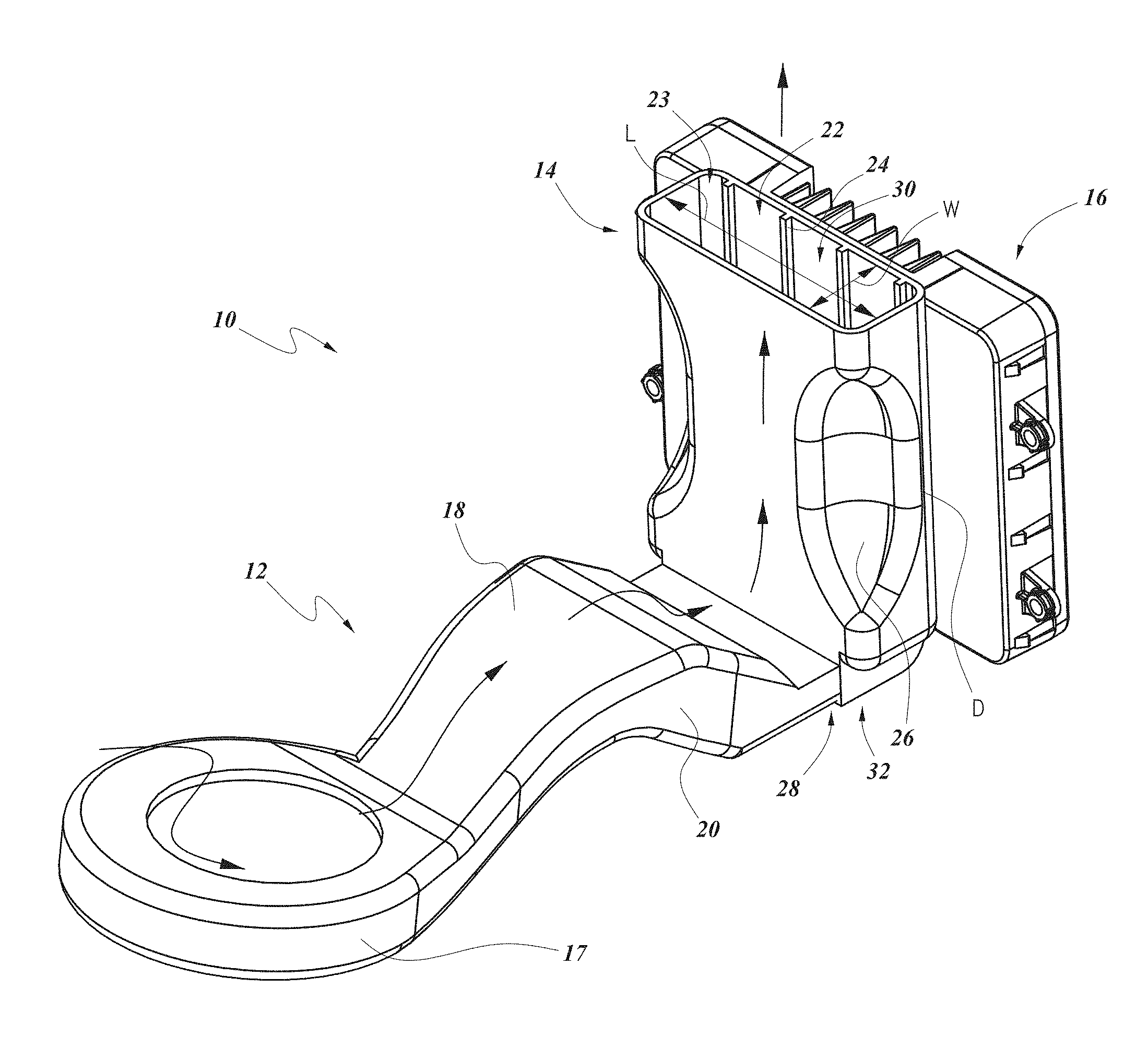
FIG. 1 illustrates a perspective view of an embodiment of a cooling system for an induction charger with a thermal conditioning module connected with a dock.
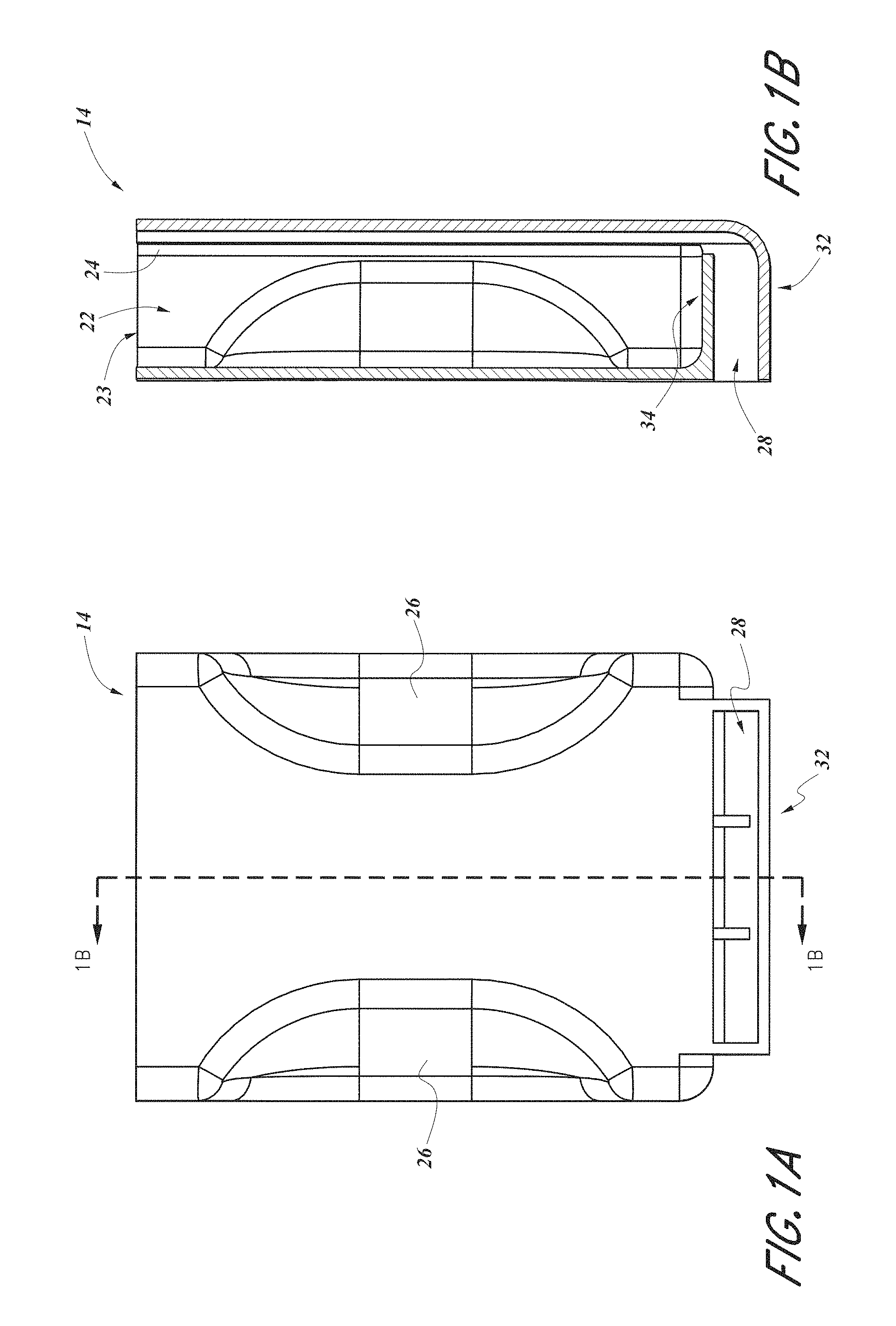
FIG. 1A illustrates a front view of the dock of FIG. 1.
FIG. 1B illustrates a cross-sectional view of the dock of FIG. 1A taken along the line 1B-1B.
FIG. 2 illustrates a perspective view of another embodiment of a cooling system for an induction charger with a thermal conditioning module connected with a dock.
FIG. 2A illustrates a front view of the dock of FIG. 2.
FIG. 2B illustrates a cross-sectional view of the dock of FIG. 2A taken along the line 2B-2B.
FIG. 3 illustrates a front perspective view of another embodiment of a cooling system for an induction charger comprising a thermal conditioning module connected with an induction charging module, which is connected with a dock.
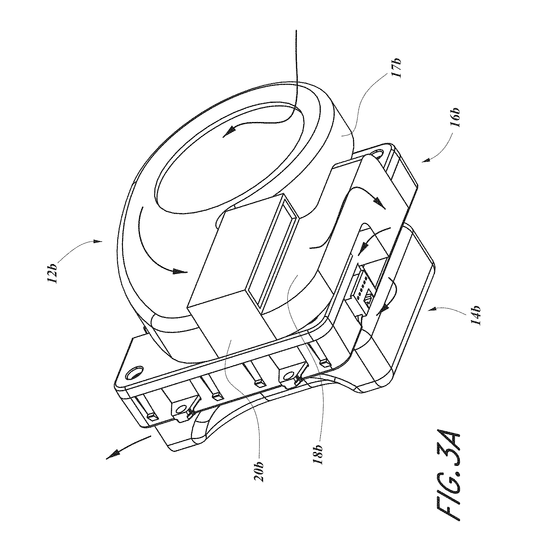
FIG. 3A illustrates a bottom perspective view of the system of FIG. 3.
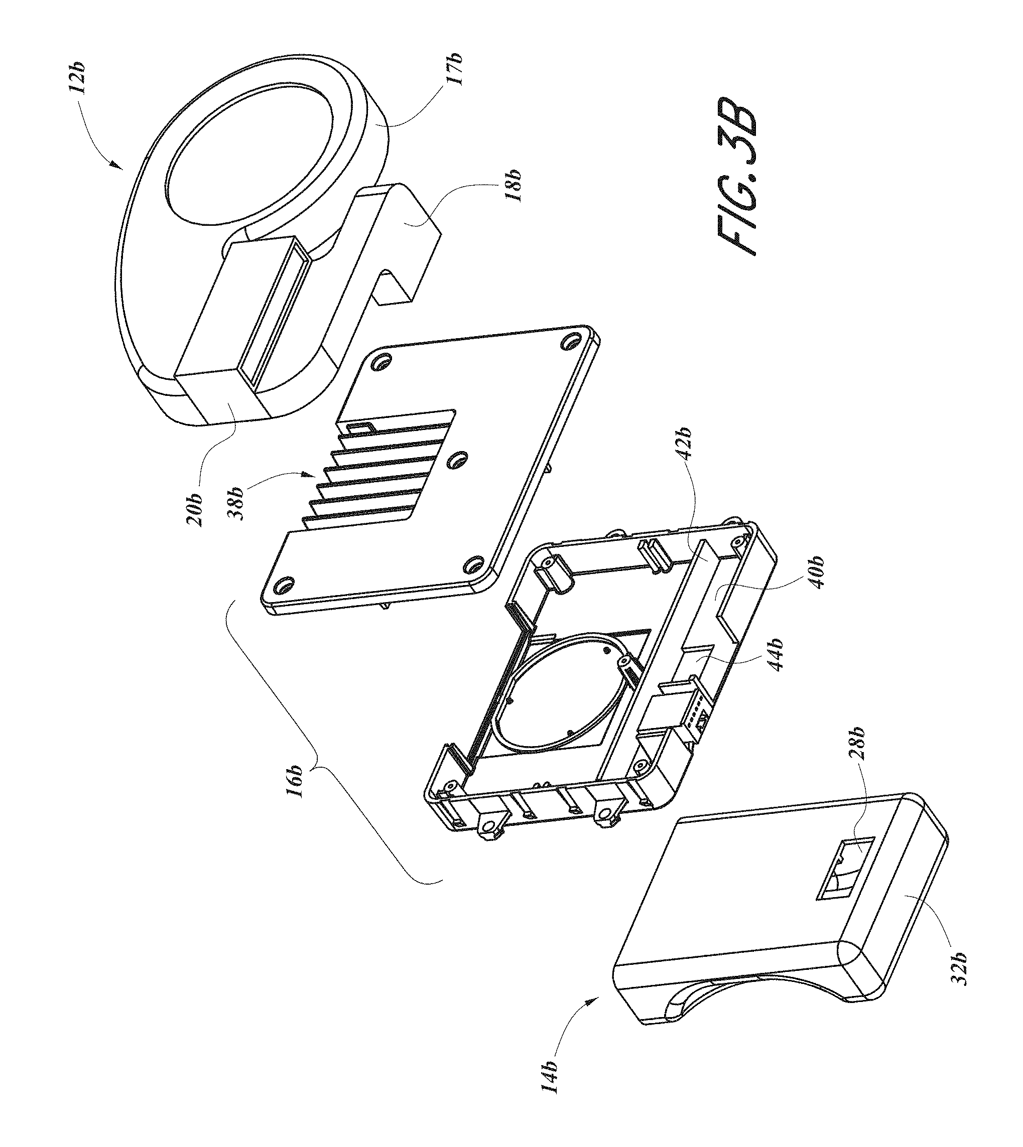
FIG. 3B illustrates an exploded bottom perspective view of the cooling system of FIG. 3A.
FIG. 4 illustrates a schematic view of a cooling system for an inductive charger according to an embodiment.
DETAILED DESCRIPTION
With reference to FIGS. 1 and 4, in some embodiments, a cooling system for an induction charger 10 includes a thermal conditioning module 12 in fluid communication with an induction charging assembly 21, which includes a dock 14 (e.g., a pad, recess, slot, opening, and/or the like) and an induction charging module 16. As shown, the induction charging module 16 can be mounted on, near, or adjacent the dock 14 so as to provide inductive charging functionality to PEDs, such as PED 19 (e.g., smartphones, other mobile phones, music playing devices, tablets, personal digital assistants (PDAs), etc.) that are configured to accept inductive charging and are placed in and/or on the dock 14.
In some embodiments, the thermal conditioning module 12 includes one more of the following: a fluid transfer device (such as, e.g., a pump, blower, or fan 17), ducting 18 (e.g., a fluid line, coupling, piping, etc.) thermal conditioning devices 20 (e.g., thermoelectric devices (TEDs), conductive heat transfer devices, other cooling or ventilation devices, etc.), sensors (e.g., temperature sensors, humidity sensors, condensation sensors, etc.), timers and/or the like. Any of various types of fluid transfer devices 17 (e.g., fans) can be used in such modules or devices, such as radial fans (e.g., squirrel cage fans), axial fans, propeller fans, and/or the like. In certain embodiments, the fluid transfer device 17 is configured to draw air from near a floor or lower portion of the vehicle 25, which can be beneficial because such air may be cooler than air originating from other locations of the vehicle (e.g., due to a reduction in sun loading or otherwise). As illustrated, the ducting 18 can be in fluid communication with the fan 17 or other fluid transfer device. In addition, depending on the configuration of the module, such components can also be in fluid communication with a thermal conditioning device 20 (e.g., TED), the dock 14, one or more sensors, and/or any other components or devices, as desired or required. In some variants, the ducting 18 is in fluid communication with the dock 14 via an opening 28 in the dock 14. Certain implementations include the fan 17 and TED 20 in a single housing. However, in alternative embodiments, one or more components can be included in separate (e.g., adjacent or non-adjacent) housing or casings.
As noted above, the thermal conditioning device 20 can comprise a TED, for example, a Peltier device, which can include at least one pair of dissimilar materials connected electrically in series and thermally in parallel. In some embodiments, the dissimilar materials are mounted between a pair of plates positioned on the cold and hot sides of the device. The plates can provide for heat conduction and electrical insulation. A thermal interface material (e.g., grease, pad, or solder) can be used to conductively couple the cold or hot side plate to a conduction member, such as fins or the like. Fluid, such as air, can be passed over the conduction member to transfer heat by convection. In other embodiments, one or more intermediate elements (e.g., conduction elements) can be provided between the plates and the conduction element and/or the dock 14, thereby transferring heat between the TED 20 and the dock 14 by conduction.
In some embodiments, the dissimilar materials comprise a series of n-type and p-type semiconductor elements that are connected electrically in series and thermally in parallel. An electrical circuit is configured to pass current through the dissimilar materials so as to selectively create a cooled (and an oppositely oriented heated) side. Depending on the direction of electrical current passing through the thermoelectric device, one side of the device will be heated and the opposing side will be cooled.
In some embodiments, a controller (not shown) controls the operation of the thermal conditioning module 12. For example, the controller can allow the user to regulate when the thermal conditioning module 12 is activated and deactivated. In some embodiments, the controller receives an input from a sensor (e.g., a temperature sensor, a humidity sensor, a condensation sensor, etc.), which can be used in a control algorithm that helps regulate the operation (e.g., on or off, duty cycle, etc.) of the thermal conditioning device 20 (e.g., TED). Such an algorithm can be configured to provide for a desired cooling effect for the module, for fault protection, safety reasons, and/or the like. In certain variants, the controller is configured to communicate with, or receive signals from, other systems of the vehicle. For example, the controller can be in data communication with a signal that is indicative of whether the vehicle is in operation (e.g., the ignition has been activated), an occupant is positioned in the vehicle, and/or the like. Thus, in some such embodiments, the controller can be configured to allow the thermal conditioning module 12 to operate only if certain conditions are met (e.g., the vehicle is operating, an occupant is positioned in an adjacent seat, temperature/humidity levels are within a specific range, etc.). Electrical power from the vehicle's electrical system can be provided to the controller, fluid transfer device 17 (e.g., fan or blower), TED or other thermal conditioning device 20, sensors and/or any other components via electrical wires and/or some other direct or indirect electrical connection (not shown).
In some embodiments, the dock 14 is sized, shaped and otherwise configured to accept a PED. For example, the dock 14 can be configured to contain, hold, and/or embrace the PED. Such a configuration can provide a place to store the PED, which can be helpful in restricting, partially or completely, inadvertent movement of the PED during operation of the vehicle (e.g., while driving). In certain embodiments, the dock 14 is configured such that a cell phone or other PED can be slidingly inserted into and removed from the dock 14. Some implementations have the dock 14 positioned in a dashboard or center console of an automobile, although various other locations are contemplated as well (e.g., in or near a door, a glove box or other storage container, an armrest, a rear seat console and/or the like).
Some embodiments of the dock 14 comprise a cavity 22, which can be sized, shaped and otherwise configured to receive a PED. For example, the cavity 22 can include an aperture 23 through which a cell phone or other PED can be inserted. In some embodiments, the aperture 23 has a width W and a length L that are sized and otherwise configured such that a cell phone or other PED can be inserted through the aperture 23 and at least partially into the cavity 22. Some variants of the aperture 23 have a length L of at least about: 2.0 inches, 2.5 inches, 2.75 inches, 3.0 inches, 3.25 inches, values in between, or otherwise. Some embodiments of the aperture 23 have a width W of at least about: 0.25 inches, 0.38 inches, 0.50 inches, 0.62 inches, values in between, or otherwise. In other embodiments, however, the aperture can be sized and configured to accommodate a PED having a length and/or width greater than indicated above. For example, the aperture can be configured to receive a tablet or other relatively large PED therein. In certain implementations, the cavity 22 is in fluid communication with the ambient environment surrounding the dock 14. In some embodiments, the cavity 22 can be configured to receive at least about 75% (e.g., about 70%, 72%, 74%, 76%, 78%, 80%, ranges between the foregoing percentages) of the volume of a cell phone or other PED. In other embodiments, however, the cavity 22 can be configured to receive greater than about 80% of the PED (e.g., about 80%, 85%, 90%, 95%, 100%, values between the foregoing percentages, etc.) or less than about 70% of the PED (e.g., about 40%, 45%, 50%, 55%, 60%, 65%, 70%, values between the foregoing percentages, less than about 40%, etc.), as desired or required. In some embodiments, the cavity 22 has a volume of at least about 4 cubic inches.
Some embodiments of the cavity 22 are configured to receive all or a substantial portion of the longitudinal length of a cell phone or other PED. Such a configuration can, for example, facilitate securing and/or concealing (e.g., partially or completely) the cell phone or other PED. Certain embodiments of the cavity 22 have a depth D (also called a height) of at least about: 3.0 inches, 3.5 inches, 4.0 inches, 4.5 inches, 5.0 inches, values in between, or otherwise. In some embodiments, the cavity 22 is configured to receive only a portion of the longitudinal length of a PED, thereby providing a region, portion, or section (e.g., the portion of the PED that is not received in the cavity 22) to grasp to facilitate moving or otherwise handling (e.g., removing) the PED relative to the cavity 22. In other embodiments, the cavity 22 is configured to receive the entire or substantially the entire longitudinal length of the PED.
In some embodiments, the dock 14 comprises one or more stabilizing members, such as, for example, ribs or other protruding members 24. In some variants, the ribs 24 protrude at least partially into the cavity 22 and are configured to contact a PED that is inserted into the cavity 22, thereby reducing or restricting vibration and/or other movement of the PED relative to the dock 14. In some embodiments, the ribs 24 comprise one or more resilient materials, such rubber, plastic and/or the like. The ribs or other protruding members 24 can comprise one or more other materials and/or components, either in addition to or in lieu of plastic and/or rubber, as desired or required. For example, the ribs can include one or more springs or other resilient members or materials. Certain variants of the ribs have a length (parallel to L) of less than or equal to about 2.0 mm. In some embodiments, the ribs 24 extend along generally the entire depth of the dock 14. In some embodiments, the ribs 24 are configured to promote fluid flow when a PED is installed in the cavity 22, as will be discussed in further detail below. As shown, certain variants of the dock 14 include sculpted or other special features, such as shoulders 26, which also can be configured to facilitate stabilization and/or securement (e.g., grasping) of a PED that is inserted into the cavity 22. Some variants of the shoulders 26 include curves or angles so as to direct a PED into general alignment with the dock 14 during installation of the PED into the dock 14.
During operation of the cooling system for an induction charger 10, and as indicated by the arrows in FIG. 1, fluid (e.g., air) enters the fluid transfer device 17 (e.g., fan, blower, etc.) via an upper or lower aperture, and is encouraged into the ducting 18. The air passes over and/or through the thermal conditioning device 20 (e.g., TED), causing heat transfer between the thermal conditioning device 20 and the air or other fluid passing through or near it, thereby decreasing the temperature of the air or fluid. In some embodiments, the cooled air is directed, at least partially, into the dock 14. In certain implementations, the cooled air travels at least partially along at least some of depth of the dock 14, and along some, substantially all, or all of the height of the PED positioned within the dock. Accordingly, heat from the inductive charging assembly and/or PED can be advantageously transferred via convection to the cooled air (e.g., to cool the air), thereby transferring heat away from the PED and at least partially offsetting the heat generated by the inductive charging assembly and/or PED. The air can emerge from the dock 14 into the ambient environment of the vehicle. In some embodiments, such discharged air can be routed to one or more portions of the vehicle (e.g., the exterior of the vehicle, below or away from the console or seat assembly, etc.), as desired or required.
As noted above, in some embodiments, the dock 14 comprises one or more ribs or other protruding members 24, which can be configured to promote fluid flow even when a PED is positioned at least partially in the dock 14. In some embodiments, the ribs 24 are positioned and otherwise configured to at least partially define and maintain one or more channels 30. Thus, when a PED is positioned in the dock 14, a substantial volume of the cavity 22 may be occupied by the PED, thus restricting fluid flow. However, the ribs 24 and the corresponding channels 30 that they help define can be configured to maintain a space between the PED and a wall of the dock 14, and thus maintain a path through which air or other fluid may pass. In some embodiments, a bottom end 32 of the dock 14 (e.g., the portion which is adjacent or near a lower portion a PED that is positioned within the dock 14) comprises one or more ribs, dimples, grooves, protruding member and/or other features configured to promote airflow between the bottom of the PED and the bottom end 32 of the dock 14. One or more spaces between the PED and certain adjacent portions of the dock can advantageously promote the cooling effect on the PED when the system is in use.
In certain embodiments, such as is shown in FIGS. 1, 1A, and 1B, air from the fluid transfer device is configured to enter at or near the bottom end 32 of the dock 14. In such embodiments, the opening 28 in the dock 14 can be positioned at or near the bottom end 32. As illustrated in FIG. 1B, the dock 14 can include a support member 34 that extends from one generally vertical wall of the dock 14 toward an opposite generally vertical wall. In some implementations, the support member is configured to receive the bottom of a PED that is received in the dock 14. As shown, the support member 34 can be disposed a particular distance apart from the bottom end 32, thus the support member 34 can space the PED away from the bottom end 32 to facilitate airflow underneath the PED. In certain embodiments, the support member directs air toward one or more of the channels 30. As discussed herein, in at least some configurations, such spaces, channels, and other features can further facilitate in promoting efficient and effective cooling of a PED.
FIGS. 2, 2A, and 2B illustrate another embodiment of a cooling system for an induction charger 10a. Several features and components of the cooling system for an induction charger 10a illustrated therein are identical or similar in form and function to those described above with respect to the cooling system for an induction charger 10, and have been provided with like numerals, with the addition of "a." Any features and/or components of the disclosed embodiments can be combined or used interchangeably.
In some embodiments, air or other fluid enters the dock 14a at a location between the top and bottom end 32a of the dock 14a. For example, the opening 28a can be located about half-way along the depth D of the dock 14a. Such a configuration can, for example, reduce the likelihood of spilled liquids or debris migrating into the fan 17a, ducting 18a, thermal conditioning device 20a (e.g., TED), other electrical and/or other. Sensitive components. For example, as the opening 28a is disposed a distance above the bottom end 32a, spilled liquid (such as water, coffee, soft drinks, etc.) or debris (such as crumbs, other food items, dust, dirt, lint, etc.) can be contained in the bottom end 32a, thereby facilitating clean-up and inhibiting such spills from entering the fan 17a, ducting 18a, and/or thermal conditioning device 20a.
As illustrated in FIG. 2B, the dock 14a can include one or more vanes 36a, which can be positioned near or adjacent the opening 28a. In certain embodiments, the vane 36a extends partly from one wall of the dock 14a and is configured to provide a desired space between the vane 36a and the opposite wall such that a PED can be inserted therebetween. In some variants, the vane 36a is configured to at least partially direct fluid flow, as desired or required. For example, the vane 36a can direct some or all of the fluid (e.g., air) passing through the opening 28a toward the bottom end 32a. As shown, the ribs or other protruding members 24a can extend along the bottom end 32a, thereby providing an elevated support surface on which the PED can rest while allowing the fluid to flow under the PED and through the channels 30a.
FIGS. 3, 3A, and 3B illustrate another embodiment of a cooling system for an induction charger 10b. Several features and components of the cooling system for an induction charger 10b are identical or similar in form and function to those described above with respect to the cooling systems for an induction charger 10, 10a and have been provided with like numerals, with the addition of "b." Any features and/or components of the disclosed embodiments can be combined or used interchangeably.
With continued reference to FIGS. 3, 3A, and 3B, in certain embodiments, air or other fluid is directed through a portion of the induction charging module 16b. As illustrated, the induction charging module 16b can be disposed between the dock 14b and the fan 17b and/or the thermal conditioning device 20b (e.g., TED). Such a configuration can, for example, reduce the space occupied by the system 10b. Further, in certain embodiments, such a configuration can enhance the heat dissipation from the induction charging module 16b. For example, in some embodiments, holes or other openings (not shown) in the ducting 18b direct fluid toward and/or along fins 38b of the induction charging module 16b.
In some embodiments, a duct, coupling or other fluid passage 18b fluidly connects the fluid transfer device 17b (e.g., fan) and with an interior portion 40b of the induction charging module 16b. For example, the interior portion 40b can be configured to receive or mate with the ducting 18b. In certain variants, the interior portion 40b is divided from another portion of the induction charging module 16b by one or more baffles, dividing members and/or other barriers 42b, which can prevent, inhibit or reduce the likelihood of the migration of dirt, dust, other particles, or other undesirable substances from reaching the electronic components of the induction charging module 16b. In some embodiments, such a barrier 42b is configured to direct the flow of fluid, for example, toward a front wall of the induction charging module 16b. As illustrated in FIG. 3B, the interior portion 40b can be positioned in a bottom portion of the induction charging module 16b, but the interior portion can be located in any location, such as, for example, on a side or the top of the induction charging module 16b and/or the like, as desired or required.
The front wall of the induction charging module 16b can include an aperture or other opening 44b that is configured to at least partially align or otherwise coincide with the opening 28b of the dock 14b when the induction charging module 16b and the dock 14b are mounted together. Such a configuration can allow fluid in the interior portion 40b to flow into the dock 14b. Accordingly, during operation of the system 10, and as is shown by the arrows in FIG. 3A, air or other fluid can flow from the fan or other fluid transfer device 17b along and/or through the TED or other thermal conditioning device 20b, thereby thermally conditioning (e.g., cooling and/or dehumidifying) the air in a desired manner. The conditioned air can flow through the ducting 18b into the interior portion 40b, through the aperture 44b and the opening 28b, and ultimately into the dock 14b. As previously discussed, conditioned air can be warmed by, and this its cooling effect at least partially offset, heat generated from the induction charging module 16b and/or the PED. In some embodiments, air exits the dock 14b and enters the vehicle's ambient environment, for example, by flowing through the channels 30b and between the ribs 24b.
Various embodiments of the cooling systems for an induction charger 10, 10a, 10b are configured to operate with an ambient air temperature of less than or equal to about 85.degree. C. In some implementations, the cooling systems for an induction charger 10, 10a, 10b are configured to provide at least about: 4 watts, 5, watts, 6 watts, 7 watts, 8 watts, 9 watts, values in between the foregoing, and/or the like of heat dissipation. In other embodiments, the cooling system is configured to provide less than 4 watts or greater than about 9 watts of heat dissipation. In some embodiments, the cooling systems for an induction charger 10, 10a, 10b are configured to dissipate at least about 4 watts generated by the induction charging module 16, 16a, 16b and at least about 3 watts generated by the PED. In certain embodiments, the cooling systems for an induction charger 10, 10a, 10b are configured to offset at least about: 50%, 60%, 70%, 80%, 85%, 90%, 95%, 99%, 100%, values in between, or otherwise, of the heat generated by the induction charging assembly during induction charging of the portable electronic device. In certain variants, the cooling systems for an induction charger 10, 10a, 10b are configured to offset all or substantially all of the heat generated by the induction charging assembly during induction charging of the portable electronic device. In some implementations, the cooling systems for an induction charger 10, 10a, 10b are configured to offset more than the heat generated by the induction charging assembly during induction charging of the portable electronic device.
For purposes of summarizing the inventions disclosed herein and the advantages achieved over the prior art, certain objects and advantages of the inventions are described herein. Of course, it is to be understood that not necessarily all such objects or advantages need to be achieved in accordance with any particular embodiment. Thus, for example, those skilled in the art will recognize that the inventions may be embodied or carried out in a manner that achieves or optimizes one advantage or group of advantages as taught or suggested herein without necessarily achieving other objects or advantages as may be taught or suggested herein.
As will be apparent, the features and attributes of the specific embodiments disclosed herein may be combined in different ways to form additional embodiments, all of which fall within the scope of the present disclosure.
Conditional language used herein, such as, among others, "can," "could," "might," "may," "e.g.," and the like, unless specifically stated otherwise, or otherwise understood within the context as used, is generally intended to convey that certain embodiments include, while other embodiments do not include, certain features, elements and/or states. Thus, such conditional language is not generally intended to imply that features, elements and/or states are in any way required for one or more embodiments or that one or more embodiments necessarily include logic for deciding, with or without author input or prompting, whether these features, elements and/or states are included or are to be performed in any particular embodiment.
Many variations and modifications may be made to the herein-described embodiments, the elements of which are to be understood as being among other acceptable examples. All such modifications and variations are intended to be included herein within the scope of this disclosure and protected by the following claims.
* * * * *
D00000
D00001
D00002
D00003
D00004
D00005
D00006
D00007
D00008
XML
uspto.report is an independent third-party trademark research tool that is not affiliated, endorsed, or sponsored by the United States Patent and Trademark Office (USPTO) or any other governmental organization. The information provided by uspto.report is based on publicly available data at the time of writing and is intended for informational purposes only.
While we strive to provide accurate and up-to-date information, we do not guarantee the accuracy, completeness, reliability, or suitability of the information displayed on this site. The use of this site is at your own risk. Any reliance you place on such information is therefore strictly at your own risk.
All official trademark data, including owner information, should be verified by visiting the official USPTO website at www.uspto.gov. This site is not intended to replace professional legal advice and should not be used as a substitute for consulting with a legal professional who is knowledgeable about trademark law.