Maintenance feature in magnetic implant
Pool , et al. Sept
U.S. patent number 10,405,891 [Application Number 15/699,711] was granted by the patent office on 2019-09-10 for maintenance feature in magnetic implant. This patent grant is currently assigned to NuVasive Specialized Orthopedics, Inc.. The grantee listed for this patent is NuVasive Specialized Orthopedics, inc.. Invention is credited to Arvin Chang, Scott Pool.


View All Diagrams
| United States Patent | 10,405,891 |
| Pool , et al. | September 10, 2019 |
Maintenance feature in magnetic implant
Abstract
A distraction system includes a distraction rod having one end configured for affixation to at a first location on patient. The system further includes an adjustable portion configured for placement in the patient at a second location, the adjustable portion comprising a housing containing a magnetic assembly comprising a magnet, the magnetic assembly secured to a threaded element that interfaces with an opposing end of the distraction rod. The system includes a magnetically permeable member in proximity to the magnetic assembly and covering an arc of less than 360.degree. of the adjustable portion.
| Inventors: | Pool; Scott (Laguna Hills, CA), Chang; Arvin (Yorba Linda, CA) | ||||||||||
|---|---|---|---|---|---|---|---|---|---|---|---|
| Applicant: |
|
||||||||||
| Assignee: | NuVasive Specialized Orthopedics,
Inc. (San Diego, CA) |
||||||||||
| Family ID: | 45556692 | ||||||||||
| Appl. No.: | 15/699,711 | ||||||||||
| Filed: | September 8, 2017 |
Prior Publication Data
| Document Identifier | Publication Date | |
|---|---|---|
| US 20170367737 A1 | Dec 28, 2017 | |
Related U.S. Patent Documents
| Application Number | Filing Date | Patent Number | Issue Date | ||
|---|---|---|---|---|---|
| 14883485 | Oct 14, 2015 | 9757159 | |||
| 14250313 | Nov 17, 2015 | 9186183 | |||
| 13198571 | May 27, 2014 | 8734488 | |||
| 61372020 | Aug 9, 2010 | ||||
| Current U.S. Class: | 1/1 |
| Current CPC Class: | A61B 17/707 (20130101); A61B 17/7004 (20130101); A61B 17/7016 (20130101); A61B 17/7011 (20130101); A61B 2017/00212 (20130101); A61B 2017/00199 (20130101); A61B 2017/00411 (20130101) |
| Current International Class: | A61B 17/70 (20060101) |
References Cited [Referenced By]
U.S. Patent Documents
| 1599538 | September 1926 | Mintrop |
| 2702031 | February 1955 | Wenger |
| 3111945 | November 1963 | Solbrig |
| 3372476 | March 1968 | Peiffer |
| 3377576 | April 1968 | Langberg |
| 3397928 | August 1968 | Galle |
| 3512901 | May 1970 | Law |
| 3527220 | September 1970 | Summers |
| 3597781 | August 1971 | Eibes |
| 3726279 | April 1973 | Barefoot et al. |
| 3749098 | July 1973 | De Bennetot |
| 3750194 | August 1973 | Summers |
| 3810259 | May 1974 | Summers |
| 3840018 | October 1974 | Heifetz |
| 3900025 | August 1975 | Barnes, Jr. |
| 3915151 | October 1975 | Kraus |
| 3976060 | August 1976 | Hildebrandt et al. |
| 4010758 | March 1977 | Rockland et al. |
| 4056743 | November 1977 | Clifford et al. |
| 4068821 | January 1978 | Morrison |
| 4078559 | March 1978 | Nissinen |
| 4118805 | October 1978 | Reimels |
| 4204541 | May 1980 | Kapitanov |
| 4222374 | September 1980 | Sampson et al. |
| 4235246 | November 1980 | Weiss |
| 4256094 | March 1981 | Kapp et al. |
| 4300223 | November 1981 | Maire |
| 4357946 | November 1982 | Dutcher et al. |
| 4386603 | June 1983 | Mayfield |
| 4395259 | July 1983 | Prestele et al. |
| 4448191 | May 1984 | Rodnyansky et al. |
| 4486176 | December 1984 | Tardieu et al. |
| 4501266 | February 1985 | McDaniel |
| 4522501 | June 1985 | Shannon |
| 4537520 | August 1985 | Ochiai et al. |
| 4550279 | October 1985 | Klein |
| 4561798 | December 1985 | Elcrin et al. |
| 4573454 | March 1986 | Hoffman |
| 4592339 | June 1986 | Kuzmak et al. |
| 4592355 | June 1986 | Antebi |
| 4595007 | June 1986 | Mericle |
| 4642257 | February 1987 | Chase |
| 4658809 | April 1987 | Ulrich et al. |
| 4696288 | September 1987 | Kuzmak et al. |
| 4700091 | October 1987 | Wuthrich |
| 4747832 | May 1988 | Buffet |
| 4760837 | August 1988 | Petit |
| 4854304 | August 1989 | Zielke |
| 4904861 | February 1990 | Epstein et al. |
| 4931055 | June 1990 | Bumpus et al. |
| 4940467 | July 1990 | Tronzo |
| 4957495 | September 1990 | Kluger |
| 4973331 | November 1990 | Pursley et al. |
| 5010879 | April 1991 | Moriya et al. |
| 5030235 | July 1991 | Campbell, Jr. |
| 5041112 | August 1991 | Mingozzi et al. |
| 5064004 | November 1991 | Lundell |
| 5074868 | December 1991 | Kuzmak |
| 5074882 | December 1991 | Grammont et al. |
| 5092889 | March 1992 | Campbell, Jr. |
| 5133716 | July 1992 | Plaza |
| 5142407 | August 1992 | Varaprasad et al. |
| 5152770 | October 1992 | Bengmark et al. |
| 5156605 | October 1992 | Pursley et al. |
| 5176618 | January 1993 | Freedman |
| 5226429 | July 1993 | Kuzmak |
| 5261908 | November 1993 | Campbell, Jr. |
| 5263955 | November 1993 | Baumgart et al. |
| 5290289 | March 1994 | Sanders et al. |
| 5306275 | April 1994 | Bryan |
| 5330503 | July 1994 | Yoon |
| 5334202 | August 1994 | Carter |
| 5336223 | August 1994 | Rogers |
| 5356411 | October 1994 | Spievack |
| 5356424 | October 1994 | Buzerak et al. |
| 5360407 | November 1994 | Leonard et al. |
| 5364396 | November 1994 | Robinson et al. |
| 5403322 | April 1995 | Herzenberg et al. |
| 5429638 | July 1995 | Muschler et al. |
| 5433721 | July 1995 | Hooven et al. |
| 5437266 | August 1995 | McPherson et al. |
| 5449368 | September 1995 | Kuzmak |
| 5466261 | November 1995 | Richelsoph |
| 5468030 | November 1995 | Walling |
| 5480437 | January 1996 | Draenert |
| 5509888 | April 1996 | Miller |
| 5516335 | May 1996 | Kummer et al. |
| 5527309 | June 1996 | Shelton |
| 5536269 | July 1996 | Spievack |
| 5536296 | July 1996 | Ten Eyck et al. |
| 5549610 | August 1996 | Russell et al. |
| 5573012 | November 1996 | McEwan |
| 5575790 | November 1996 | Chen et al. |
| 5582616 | December 1996 | Bolduc et al. |
| 5620445 | April 1997 | Brosnahan et al. |
| 5620449 | April 1997 | Faccioli et al. |
| 5626579 | May 1997 | Muschler et al. |
| 5626613 | May 1997 | Schmieding |
| 5632744 | May 1997 | Campbell, Jr. |
| 5659217 | August 1997 | Petersen |
| 5662683 | September 1997 | Kay |
| 5672175 | September 1997 | Martin |
| 5672177 | September 1997 | Seldin |
| 5700263 | December 1997 | Schendel |
| 5704893 | January 1998 | Timm |
| 5704938 | January 1998 | Staehlin et al. |
| 5704939 | January 1998 | Justin |
| 5720746 | February 1998 | Soubeiran |
| 5743910 | April 1998 | Bays et al. |
| 5762599 | June 1998 | Sohn |
| 5771903 | June 1998 | Jakobsson |
| 5800434 | September 1998 | Campbell, Jr. |
| 5810815 | September 1998 | Morales |
| 5827286 | October 1998 | Incavo et al. |
| 5829662 | November 1998 | Allen et al. |
| 5830221 | November 1998 | Stein et al. |
| 5879375 | March 1999 | Larson, Jr. et al. |
| 5902304 | May 1999 | Walker et al. |
| 5935127 | August 1999 | Border |
| 5938669 | August 1999 | Klaiber et al. |
| 5945762 | August 1999 | Chen et al. |
| 5961553 | October 1999 | Coty et al. |
| 5976138 | November 1999 | Baumgart et al. |
| 5979456 | November 1999 | Magovern |
| 6022349 | February 2000 | McLeod et al. |
| 6033412 | March 2000 | Losken et al. |
| 6034296 | March 2000 | Elvin et al. |
| 6067991 | May 2000 | Forsell |
| 6074341 | June 2000 | Anderson et al. |
| 6074882 | June 2000 | Eckardt |
| 6102922 | August 2000 | Jakobsson et al. |
| 6106525 | August 2000 | Sachse |
| 6126660 | October 2000 | Dietz |
| 6126661 | October 2000 | Faccioli et al. |
| 6138681 | October 2000 | Chen et al. |
| 6139316 | October 2000 | Sachdeva et al. |
| 6162223 | December 2000 | Orsak et al. |
| 6183476 | February 2001 | Gerhardt et al. |
| 6200317 | March 2001 | Aalsma et al. |
| 6210347 | April 2001 | Forsell |
| 6234956 | May 2001 | He et al. |
| 6241730 | June 2001 | Alby |
| 6245075 | June 2001 | Betz et al. |
| 6283156 | September 2001 | Motley |
| 6315784 | November 2001 | Djurovic |
| 6319255 | November 2001 | Grundei et al. |
| 6331744 | December 2001 | Chen et al. |
| 6336929 | January 2002 | Justin |
| 6343568 | February 2002 | McClasky |
| 6358283 | March 2002 | Hogfors et al. |
| 6375682 | April 2002 | Fleischmann et al. |
| 6386083 | May 2002 | Hwang |
| 6389187 | May 2002 | Greenaway et al. |
| 6400980 | June 2002 | Lemelson |
| 6402753 | June 2002 | Cole et al. |
| 6409175 | June 2002 | Evans et al. |
| D460184 | July 2002 | Schendel et al. |
| 6416516 | July 2002 | Stauch et al. |
| 6417750 | July 2002 | Sohn |
| 6432040 | August 2002 | Meah |
| 6450173 | September 2002 | Forsell |
| 6450946 | September 2002 | Forsell |
| 6453907 | September 2002 | Forsell |
| 6454698 | September 2002 | Forsell |
| 6454699 | September 2002 | Forsell |
| 6454700 | September 2002 | Forsell |
| 6454701 | September 2002 | Forsell |
| 6460543 | October 2002 | Forsell |
| 6461292 | October 2002 | Forsell |
| 6461293 | October 2002 | Forsell |
| 6463935 | October 2002 | Forsell |
| 6464628 | October 2002 | Forsell |
| 6470892 | October 2002 | Forsell |
| 6471635 | October 2002 | Forsell |
| 6475136 | November 2002 | Forsell |
| 6482145 | November 2002 | Forsell |
| 6494879 | December 2002 | Lennox et al. |
| 6499907 | December 2002 | Baur |
| 6500110 | December 2002 | Davey et al. |
| 6503189 | January 2003 | Forsell |
| 6508820 | January 2003 | Bales |
| 6510345 | January 2003 | Van Bentem |
| 6511490 | January 2003 | Robert |
| 6527701 | March 2003 | Sayet et al. |
| 6527702 | March 2003 | Whalen et al. |
| 6536499 | March 2003 | Voorhees et al. |
| 6537196 | March 2003 | Creighton, IV et al. |
| 6547801 | April 2003 | Dargent et al. |
| 6554831 | April 2003 | Rivard et al. |
| 6558400 | May 2003 | Deem et al. |
| 6565573 | May 2003 | Ferrante et al. |
| 6565576 | May 2003 | Stauch et al. |
| 6582313 | June 2003 | Perrow |
| 6583630 | June 2003 | Mendes et al. |
| 6587719 | July 2003 | Barrett et al. |
| 6604529 | August 2003 | Kim |
| 6609025 | August 2003 | Barrett et al. |
| 6616669 | September 2003 | Ogilvie et al. |
| 6626917 | September 2003 | Craig |
| 6627206 | September 2003 | Lloyd |
| 6656135 | December 2003 | Zogbi et al. |
| 6656194 | December 2003 | Gannoe et al. |
| 6657351 | December 2003 | Chen et al. |
| 6667725 | December 2003 | Simons et al. |
| 6673079 | January 2004 | Kane |
| 6676674 | January 2004 | Dudai |
| 6702816 | March 2004 | Buhler |
| 6706042 | March 2004 | Taylor |
| 6709293 | March 2004 | Mori et al. |
| 6709385 | March 2004 | Forsell |
| 6730087 | May 2004 | Butsch |
| 6749556 | June 2004 | Banik |
| 6752754 | June 2004 | Feng et al. |
| 6761503 | July 2004 | Breese |
| 6765330 | July 2004 | Baur |
| 6769499 | August 2004 | Cargill et al. |
| 6789442 | September 2004 | Forch |
| 6796984 | September 2004 | Soubeiran |
| 6802844 | October 2004 | Ferree |
| 6809434 | October 2004 | Duncan et al. |
| 6835207 | December 2004 | Zacouto et al. |
| 6849076 | February 2005 | Blunn et al. |
| 6852113 | February 2005 | Nathanson et al. |
| 6915165 | July 2005 | Forsell |
| 6916326 | July 2005 | Benchetrit |
| 6918838 | July 2005 | Schwarzler et al. |
| 6918910 | July 2005 | Smith et al. |
| 6921400 | July 2005 | Sohngen |
| 6923951 | August 2005 | Contag et al. |
| 6926719 | August 2005 | Sohngen et al. |
| 6953429 | October 2005 | Forsell |
| 6961553 | November 2005 | Zhao et al. |
| 6971143 | December 2005 | Domroese |
| 6997952 | February 2006 | Furukawa et al. |
| 7001346 | February 2006 | White |
| 7008425 | March 2006 | Phillips |
| 7011621 | March 2006 | Sayet et al. |
| 7011658 | March 2006 | Young |
| 7029472 | April 2006 | Fortin |
| 7029475 | April 2006 | Panjabi |
| 7041105 | May 2006 | Michelson |
| 7060080 | June 2006 | Bachmann |
| 7063706 | June 2006 | Wittenstein |
| 7105029 | September 2006 | Doubler et al. |
| 7105968 | September 2006 | Nissen |
| 7114501 | October 2006 | Johnson et al. |
| 7115129 | October 2006 | Heggeness |
| 7128750 | October 2006 | Stergiopulos |
| 7135022 | November 2006 | Kosashvili et al. |
| 7160312 | January 2007 | Saadat |
| 7163538 | January 2007 | Altarac et al. |
| 7172607 | February 2007 | Hofle et al. |
| 7175589 | February 2007 | Deem et al. |
| 7175660 | February 2007 | Cartledge et al. |
| 7189005 | March 2007 | Ward |
| 7191007 | March 2007 | Desai et al. |
| 7194297 | March 2007 | Talpade et al. |
| 7218232 | May 2007 | DiSilvestro et al. |
| 7238191 | July 2007 | Bachmann |
| 7241300 | July 2007 | Sharkawy et al. |
| 7255682 | August 2007 | Bartol, Jr. et al. |
| 7282023 | October 2007 | Frering |
| 7285087 | October 2007 | Moaddeb et al. |
| 7288064 | October 2007 | Boustani et al. |
| 7297150 | November 2007 | Cartledge et al. |
| 7302015 | November 2007 | Kim et al. |
| 7302858 | December 2007 | Walsh et al. |
| 7311690 | December 2007 | Burnett |
| 7314443 | January 2008 | Jordan et al. |
| 7320706 | January 2008 | Al-Najjar |
| 7338433 | March 2008 | Coe |
| 7351198 | April 2008 | Byrum et al. |
| 7351240 | April 2008 | Hassler, Jr. et al. |
| 7353747 | April 2008 | Swayze et al. |
| 7357037 | April 2008 | Hnat et al. |
| 7357635 | April 2008 | Belfor et al. |
| 7360542 | April 2008 | Nelson et al. |
| 7361192 | April 2008 | Doty |
| 7367937 | May 2008 | Jambor et al. |
| 7367938 | May 2008 | Forsell |
| 7371244 | May 2008 | Chatlynne et al. |
| 7374557 | May 2008 | Conlon et al. |
| 7390007 | June 2008 | Helms et al. |
| 7390294 | June 2008 | Hassler, Jr. |
| 7402134 | July 2008 | Moaddeb et al. |
| 7402176 | July 2008 | Malek |
| 7410461 | August 2008 | Lau et al. |
| 7416528 | August 2008 | Crawford et al. |
| 7429259 | September 2008 | Cadeddu et al. |
| 7431692 | October 2008 | Zollinger et al. |
| 7441559 | October 2008 | Nelson et al. |
| 7445010 | November 2008 | Kugler et al. |
| 7455690 | November 2008 | Cartledge et al. |
| 7458981 | December 2008 | Fielding et al. |
| 7468060 | December 2008 | Utley et al. |
| 7481763 | January 2009 | Hassler, Jr. et al. |
| 7481841 | January 2009 | Hazebrouck et al. |
| 7485149 | February 2009 | White |
| 7489495 | February 2009 | Stevenson |
| 7530981 | May 2009 | Kutsenko |
| 7531002 | May 2009 | Sutton et al. |
| 7553298 | June 2009 | Hunt et al. |
| 7559951 | July 2009 | DiSilvestro et al. |
| 7561916 | July 2009 | Hunt et al. |
| 7569057 | August 2009 | Liu et al. |
| 7584788 | September 2009 | Baron et al. |
| 7601156 | October 2009 | Robinson |
| 7601162 | October 2009 | Hassler, Jr. et al. |
| 7611526 | November 2009 | Carl et al. |
| 7618435 | November 2009 | Opolski |
| 7651483 | January 2010 | Byrum et al. |
| 7658753 | February 2010 | Carl et al. |
| 7658754 | February 2010 | Zhang et al. |
| 7666132 | February 2010 | Forsell |
| 7666184 | February 2010 | Stauch |
| 7666210 | February 2010 | Franck et al. |
| 7678139 | March 2010 | Garamszegi et al. |
| 7691103 | April 2010 | Fernandez et al. |
| 7695512 | April 2010 | Lashinski et al. |
| 7708737 | May 2010 | Kraft et al. |
| 7708762 | May 2010 | McCarthy et al. |
| 7727141 | June 2010 | Hassler, Jr. et al. |
| 7727143 | June 2010 | Birk et al. |
| 7749224 | July 2010 | Cresina et al. |
| 7753913 | July 2010 | Szakelyhidi, Jr. et al. |
| 7753915 | July 2010 | Eksler et al. |
| 7762998 | July 2010 | Birk et al. |
| 7763053 | July 2010 | Gordon |
| 7763080 | July 2010 | Southworth |
| 7766815 | August 2010 | Ortiz |
| 7766855 | August 2010 | Miethke |
| 7775099 | August 2010 | Bogath et al. |
| 7775215 | August 2010 | Hassler, Jr. et al. |
| 7776061 | August 2010 | Garner et al. |
| 7776068 | August 2010 | Ainsworth et al. |
| 7776075 | August 2010 | Bruneau et al. |
| 7776091 | August 2010 | Mastrorio et al. |
| 7787958 | August 2010 | Stevenson |
| 7793583 | September 2010 | Radinger et al. |
| 7794447 | September 2010 | Dann et al. |
| 7794476 | September 2010 | Wisnewski |
| 7811298 | October 2010 | Birk |
| 7811328 | October 2010 | Molz, IV et al. |
| 7828813 | November 2010 | Mouton |
| 7835779 | November 2010 | Anderson et al. |
| 7837691 | November 2010 | Cordes et al. |
| 7850660 | December 2010 | Uth et al. |
| 7862546 | January 2011 | Conlon et al. |
| 7862586 | January 2011 | Malek |
| 7867235 | January 2011 | Fell et al. |
| 7875033 | January 2011 | Richter et al. |
| 7887566 | February 2011 | Hynes |
| 7901381 | March 2011 | Birk et al. |
| 7901419 | March 2011 | Bachmann et al. |
| 7909839 | March 2011 | Fields |
| 7909852 | March 2011 | Boomer et al. |
| 7918844 | April 2011 | Byrum et al. |
| 7927357 | April 2011 | Sacher et al. |
| 7932825 | April 2011 | Berger |
| 7938841 | May 2011 | Sharkawy et al. |
| 7942908 | May 2011 | Sacher et al. |
| 7951067 | May 2011 | Byrum et al. |
| 7972346 | July 2011 | Bachmann et al. |
| 7987241 | July 2011 | St Jacques, Jr. et al. |
| 7988709 | August 2011 | Clark et al. |
| 7993397 | August 2011 | Lashinski et al. |
| 8002809 | August 2011 | Baynham |
| 8007474 | August 2011 | Uth et al. |
| 8011308 | September 2011 | Picchio |
| 8016745 | September 2011 | Hassler, Jr. et al. |
| 8016837 | September 2011 | Giger et al. |
| 8029477 | October 2011 | Byrum et al. |
| 8037871 | October 2011 | McClendon |
| 8043206 | October 2011 | Birk |
| 8043290 | October 2011 | Harrison et al. |
| 8043299 | October 2011 | Conway |
| 8043338 | October 2011 | Dant |
| 8057473 | November 2011 | Orsak et al. |
| 8083741 | December 2011 | Morgan et al. |
| 8092499 | January 2012 | Roth |
| 8095317 | January 2012 | Ekseth et al. |
| 8096938 | January 2012 | Forsell |
| 8100967 | January 2012 | Makower et al. |
| 8105360 | January 2012 | Connor |
| 8105363 | January 2012 | Fielding et al. |
| 8105364 | January 2012 | McCarthy et al. |
| 8123805 | February 2012 | Makower et al. |
| 8137349 | March 2012 | Soubeiran |
| 8147517 | April 2012 | Trieu et al. |
| 8147549 | April 2012 | Metcalf, Jr. et al. |
| 8162897 | April 2012 | Byrum |
| 8162979 | April 2012 | Sachs et al. |
| 8177789 | May 2012 | Magill et al. |
| 8182411 | May 2012 | Dlugos |
| 8187324 | May 2012 | Webler et al. |
| 8211149 | July 2012 | Justis |
| 8211151 | July 2012 | Schwab et al. |
| 8211179 | July 2012 | Molz, IV et al. |
| 8216275 | July 2012 | Fielding et al. |
| 8221420 | July 2012 | Keller |
| 8236002 | August 2012 | Fortin et al. |
| 8241331 | August 2012 | Arnin |
| 8251888 | August 2012 | Roslin et al. |
| 8252063 | August 2012 | Stauch |
| 8263024 | September 2012 | Wan et al. |
| 8278941 | October 2012 | Kroh et al. |
| 8282671 | October 2012 | Connor |
| 8298240 | October 2012 | Giger et al. |
| 8317802 | November 2012 | Manzi et al. |
| 8323290 | December 2012 | Metzger et al. |
| 8357169 | January 2013 | Henniges et al. |
| 8366628 | February 2013 | Denker et al. |
| 8372078 | February 2013 | Collazo |
| 8386018 | February 2013 | Stauch et al. |
| 8394124 | March 2013 | Biyani |
| 8403958 | March 2013 | Schwab |
| 8414584 | April 2013 | Brigido |
| 8419801 | April 2013 | DiSilvestro et al. |
| 8425608 | April 2013 | Dewey et al. |
| 8435268 | May 2013 | Thompson et al. |
| 8439915 | May 2013 | Harrison et al. |
| 8439926 | May 2013 | Bojarski et al. |
| 8449580 | May 2013 | Voellmicke et al. |
| 8469908 | June 2013 | Asfora |
| 8470003 | June 2013 | Voellmicke et al. |
| 8470004 | June 2013 | Reiley |
| 8475354 | July 2013 | Phillips et al. |
| 8475499 | July 2013 | Cournoyer et al. |
| 8486070 | July 2013 | Morgan et al. |
| 8486076 | July 2013 | Chavarria et al. |
| 8486110 | July 2013 | Fielding et al. |
| 8486147 | July 2013 | de Villiers et al. |
| 8494805 | July 2013 | Roche et al. |
| 8496662 | July 2013 | Novak et al. |
| 8500810 | August 2013 | Mastrorio et al. |
| 8518062 | August 2013 | Cole et al. |
| 8518086 | August 2013 | Seme et al. |
| 8523866 | September 2013 | Sidebotham et al. |
| 8529474 | September 2013 | Gupta et al. |
| 8529606 | September 2013 | Alamin et al. |
| 8529607 | September 2013 | Alamin et al. |
| 8556901 | October 2013 | Anthony et al. |
| 8556911 | October 2013 | Mehta et al. |
| 8556975 | October 2013 | Ciupik et al. |
| 8562653 | October 2013 | Alamin et al. |
| 8568457 | October 2013 | Hunziker |
| 8579979 | November 2013 | Edie et al. |
| 8585595 | November 2013 | Heilman |
| 8585740 | November 2013 | Ross et al. |
| 8591549 | November 2013 | Lange |
| 8591553 | November 2013 | Eisermann et al. |
| 8597362 | December 2013 | Shenoy et al. |
| 8613758 | December 2013 | Linares |
| 8617220 | December 2013 | Skaggs |
| 8622936 | January 2014 | Schenberger et al. |
| 8623036 | January 2014 | Harrison et al. |
| 8632544 | January 2014 | Haaja et al. |
| 8632548 | January 2014 | Soubeiran |
| 8632563 | January 2014 | Nagase et al. |
| 8632594 | January 2014 | Williams et al. |
| 8636771 | January 2014 | Butler et al. |
| 8636802 | January 2014 | Serhan et al. |
| 8641719 | February 2014 | Gephart et al. |
| 8641723 | February 2014 | Connor |
| 8657856 | February 2014 | Gephart et al. |
| 8663285 | March 2014 | Dall et al. |
| 8663287 | March 2014 | Butler et al. |
| 8668719 | March 2014 | Alamin et al. |
| 8673001 | March 2014 | Cartledge et al. |
| 8734318 | May 2014 | Forsell |
| 8758347 | June 2014 | Weiner et al. |
| 8758372 | June 2014 | Cartledge et al. |
| 8762308 | June 2014 | Najarian et al. |
| 8771272 | July 2014 | LeCronier et al. |
| 8777947 | July 2014 | Zahrly et al. |
| 8777995 | July 2014 | McClintock et al. |
| 8784482 | July 2014 | Rahdert et al. |
| 8790343 | July 2014 | McClellan et al. |
| 8790380 | July 2014 | Buttermann |
| 8790409 | July 2014 | Van den Heuvel et al. |
| 8795339 | August 2014 | Boomer et al. |
| 8801795 | August 2014 | Makower et al. |
| 8828058 | September 2014 | Elsebaie et al. |
| 8828087 | September 2014 | Stone et al. |
| 8845724 | September 2014 | Shenoy et al. |
| 8870881 | October 2014 | Rezach et al. |
| 8870959 | October 2014 | Arnin |
| 8882830 | November 2014 | Cartledge et al. |
| 8894663 | November 2014 | Giger et al. |
| 8915915 | December 2014 | Harrison et al. |
| 8915917 | December 2014 | Doherty et al. |
| 8920422 | December 2014 | Homeier et al. |
| 8945188 | February 2015 | Rezach et al. |
| 8961521 | February 2015 | Keefer et al. |
| 8961567 | February 2015 | Hunziker |
| 8968402 | March 2015 | Myers et al. |
| 8968406 | March 2015 | Arnin |
| 8992527 | March 2015 | Guichet |
| 9005298 | April 2015 | Makower et al. |
| 9022917 | May 2015 | Kasic et al. |
| 9044218 | June 2015 | Young |
| 9060810 | June 2015 | Kercher et al. |
| 9078703 | July 2015 | Arnin |
| 2001/0011543 | August 2001 | Forsell |
| 2002/0050112 | May 2002 | Koch et al. |
| 2002/0164905 | November 2002 | Bryant |
| 2003/0032857 | February 2003 | Forsell |
| 2003/0040671 | February 2003 | Somogyi et al. |
| 2003/0114731 | June 2003 | Cadeddu et al. |
| 2003/0208212 | November 2003 | Cigaina |
| 2003/0220643 | November 2003 | Ferree |
| 2003/0220644 | November 2003 | Thelen et al. |
| 2004/0023623 | February 2004 | Stauch et al. |
| 2004/0055610 | March 2004 | Forsell |
| 2004/0064030 | April 2004 | Forsell |
| 2004/0098121 | May 2004 | Opolski |
| 2004/0116773 | June 2004 | Furness et al. |
| 2004/0133219 | July 2004 | Forsell |
| 2004/0138725 | July 2004 | Forsell |
| 2004/0193266 | September 2004 | Meyer |
| 2004/0250820 | December 2004 | Forsell |
| 2004/0260319 | December 2004 | Egle |
| 2005/0002984 | January 2005 | Byrum et al. |
| 2005/0055025 | March 2005 | Zacouto et al. |
| 2005/0055039 | March 2005 | Burnett et al. |
| 2005/0070937 | March 2005 | Jambor et al. |
| 2005/0080427 | April 2005 | Govari et al. |
| 2005/0090823 | April 2005 | Bartimus |
| 2005/0119672 | June 2005 | Benchetrit |
| 2005/0131352 | June 2005 | Conlon et al. |
| 2005/0159754 | July 2005 | Odrich |
| 2005/0165440 | July 2005 | Cancel et al. |
| 2005/0192629 | September 2005 | Saadat et al. |
| 2005/0234448 | October 2005 | McCarthy |
| 2005/0234462 | October 2005 | Hershberger |
| 2005/0246034 | November 2005 | Soubeiran |
| 2005/0251109 | November 2005 | Soubeiran |
| 2005/0261779 | November 2005 | Meyer |
| 2005/0272976 | December 2005 | Tanaka et al. |
| 2006/0036259 | February 2006 | Carl et al. |
| 2006/0036323 | February 2006 | Carl et al. |
| 2006/0036324 | February 2006 | Sachs et al. |
| 2006/0079897 | April 2006 | Harrison et al. |
| 2006/0124140 | June 2006 | Forsell |
| 2006/0136062 | June 2006 | DiNello et al. |
| 2006/0142767 | June 2006 | Green et al. |
| 2006/0155279 | July 2006 | Ogilvie |
| 2006/0155347 | July 2006 | Forsell |
| 2006/0184240 | August 2006 | Jimenez et al. |
| 2006/0200134 | September 2006 | Freid et al. |
| 2006/0204156 | September 2006 | Takehara et al. |
| 2006/0211909 | September 2006 | Anstadt et al. |
| 2006/0235299 | October 2006 | Martinelli |
| 2006/0235424 | October 2006 | Vitale et al. |
| 2006/0241746 | October 2006 | Shaoulian et al. |
| 2006/0241748 | October 2006 | Lee et al. |
| 2006/0249914 | November 2006 | Dulin |
| 2006/0252983 | November 2006 | Lembo et al. |
| 2006/0271107 | November 2006 | Harrison et al. |
| 2006/0276812 | December 2006 | Hill et al. |
| 2006/0282073 | December 2006 | Simanovsky |
| 2006/0293683 | December 2006 | Stauch |
| 2007/0010814 | January 2007 | Stauch |
| 2007/0015955 | January 2007 | Tsonton |
| 2007/0021644 | January 2007 | Woolson et al. |
| 2007/0031131 | February 2007 | Griffitts |
| 2007/0043376 | February 2007 | Leatherbury et al. |
| 2007/0050030 | March 2007 | Kim |
| 2007/0055368 | March 2007 | Rhee et al. |
| 2007/0118215 | May 2007 | Moaddeb |
| 2007/0135913 | June 2007 | Moaddeb et al. |
| 2007/0173837 | July 2007 | Chan et al. |
| 2007/0179493 | August 2007 | Kim |
| 2007/0213751 | September 2007 | Scirica et al. |
| 2007/0239159 | October 2007 | Altarac et al. |
| 2007/0255088 | November 2007 | Jacobson et al. |
| 2007/0264605 | November 2007 | Belfor et al. |
| 2007/0276369 | November 2007 | Allard et al. |
| 2007/0288024 | December 2007 | Gollogly |
| 2008/0015577 | January 2008 | Loeb |
| 2008/0021454 | January 2008 | Chao et al. |
| 2008/0021455 | January 2008 | Chao et al. |
| 2008/0021456 | January 2008 | Gupta et al. |
| 2008/0033436 | February 2008 | Song et al. |
| 2008/0051784 | February 2008 | Gollogly |
| 2008/0086128 | April 2008 | Lewis |
| 2008/0091059 | April 2008 | Machold et al. |
| 2008/0108995 | May 2008 | Conway et al. |
| 2008/0140188 | June 2008 | Rahdert et al. |
| 2008/0161933 | July 2008 | Grotz et al. |
| 2008/0167685 | July 2008 | Allard et al. |
| 2008/0172063 | July 2008 | Taylor |
| 2008/0177319 | July 2008 | Schwab |
| 2008/0177326 | July 2008 | Thompson |
| 2008/0228186 | September 2008 | Gall et al. |
| 2008/0255615 | October 2008 | Vittur et al. |
| 2008/0272928 | November 2008 | Shuster |
| 2009/0076597 | March 2009 | Dahlgren et al. |
| 2009/0082815 | March 2009 | Zylber et al. |
| 2009/0088803 | April 2009 | Justis et al. |
| 2009/0093820 | April 2009 | Trieu et al. |
| 2009/0093890 | April 2009 | Gelbart |
| 2009/0163780 | June 2009 | Tieu |
| 2009/0171356 | July 2009 | Klett |
| 2009/0192514 | July 2009 | Feinberg et al. |
| 2009/0216113 | August 2009 | Meier et al. |
| 2009/0275984 | November 2009 | Kim et al. |
| 2009/0318919 | December 2009 | Robinson |
| 2010/0004654 | January 2010 | Schmitz et al. |
| 2010/0057127 | March 2010 | McGuire et al. |
| 2010/0100185 | April 2010 | Trieu et al. |
| 2010/0106192 | April 2010 | Barry |
| 2010/0114103 | May 2010 | Harrison et al. |
| 2010/0114322 | May 2010 | Clifford et al. |
| 2010/0121457 | May 2010 | Clifford et al. |
| 2010/0137872 | June 2010 | Kam et al. |
| 2010/0145449 | June 2010 | Makower et al. |
| 2010/0168751 | July 2010 | Anderson et al. |
| 2010/0228167 | September 2010 | Ilovich et al. |
| 2010/0249782 | September 2010 | Durham |
| 2010/0249847 | September 2010 | Jung et al. |
| 2010/0256626 | October 2010 | Muller et al. |
| 2010/0262160 | October 2010 | Boyden et al. |
| 2010/0262239 | October 2010 | Boyden et al. |
| 2010/0318129 | December 2010 | Seme et al. |
| 2010/0331883 | December 2010 | Schmitz et al. |
| 2011/0004076 | January 2011 | Janna et al. |
| 2011/0057756 | March 2011 | Marinescu et al. |
| 2011/0060422 | March 2011 | Makower et al. |
| 2011/0066188 | March 2011 | Seme et al. |
| 2011/0098748 | April 2011 | Jangra |
| 2011/0137347 | June 2011 | Hunziker |
| 2011/0137415 | June 2011 | Clifford et al. |
| 2011/0152725 | June 2011 | Demir et al. |
| 2011/0196371 | August 2011 | Forsell |
| 2011/0196435 | August 2011 | Forsell |
| 2011/0202138 | August 2011 | Shenoy et al. |
| 2011/0238126 | September 2011 | Soubeiran |
| 2011/0257655 | October 2011 | Copf, Jr. |
| 2011/0284014 | November 2011 | Cadeddu et al. |
| 2012/0019341 | January 2012 | Gabay et al. |
| 2012/0019342 | January 2012 | Gabay et al. |
| 2012/0053633 | March 2012 | Stauch |
| 2012/0088953 | April 2012 | King |
| 2012/0089191 | April 2012 | Altarac et al. |
| 2012/0109207 | May 2012 | Trieu |
| 2012/0116522 | May 2012 | Makower et al. |
| 2012/0116535 | May 2012 | Ratron et al. |
| 2012/0136449 | May 2012 | Makower et al. |
| 2012/0158061 | June 2012 | Koch et al. |
| 2012/0172883 | July 2012 | Sayago |
| 2012/0179215 | July 2012 | Soubeiran |
| 2012/0179273 | July 2012 | Clifford et al. |
| 2012/0203282 | August 2012 | Sachs et al. |
| 2012/0221106 | August 2012 | Makower et al. |
| 2012/0271353 | October 2012 | Barry |
| 2012/0296234 | November 2012 | Wilhelm et al. |
| 2012/0329882 | December 2012 | Messersmith et al. |
| 2013/0013066 | January 2013 | Landry et al. |
| 2013/0072932 | March 2013 | Stauch |
| 2013/0123847 | May 2013 | Anderson et al. |
| 2013/0138017 | May 2013 | Jundt et al. |
| 2013/0138154 | May 2013 | Reiley |
| 2013/0150709 | June 2013 | Baumgartner |
| 2013/0150863 | June 2013 | Baumgartner |
| 2013/0150889 | June 2013 | Fening et al. |
| 2013/0178903 | July 2013 | Abdou |
| 2013/0197639 | August 2013 | Clifford et al. |
| 2013/0211521 | August 2013 | Shenoy et al. |
| 2013/0245692 | September 2013 | Hayes et al. |
| 2013/0253344 | September 2013 | Griswold et al. |
| 2013/0253587 | September 2013 | Carls et al. |
| 2013/0261672 | October 2013 | Horvath |
| 2013/0296863 | November 2013 | Globerman et al. |
| 2013/0296864 | November 2013 | Burley et al. |
| 2013/0296940 | November 2013 | Northcutt et al. |
| 2013/0325006 | December 2013 | Michelinie et al. |
| 2013/0325071 | December 2013 | Niemiec et al. |
| 2013/0331889 | December 2013 | Alamin et al. |
| 2014/0005788 | January 2014 | Haaja et al. |
| 2014/0025172 | January 2014 | Lucas et al. |
| 2014/0039558 | February 2014 | Alamin et al. |
| 2014/0052134 | February 2014 | Orisek |
| 2014/0058392 | February 2014 | Mueckter et al. |
| 2014/0058450 | February 2014 | Arlet |
| 2014/0066987 | March 2014 | Hestad et al. |
| 2014/0067075 | March 2014 | Makower et al. |
| 2014/0088715 | March 2014 | Ciupik |
| 2014/0128920 | May 2014 | Kantelhardt |
| 2014/0142631 | May 2014 | Hunziker |
| 2014/0142698 | May 2014 | Landry et al. |
| 2014/0156004 | June 2014 | Shenoy et al. |
| 2014/0163664 | June 2014 | Goldsmith |
| 2014/0172097 | June 2014 | Clifford et al. |
| 2014/0236234 | August 2014 | Kroll et al. |
| 2014/0236311 | August 2014 | Vicatos et al. |
| 2014/0257412 | September 2014 | Patty et al. |
| 2014/0277446 | September 2014 | Clifford et al. |
| 2014/0296918 | October 2014 | Fening et al. |
| 2014/0303538 | October 2014 | Baym et al. |
| 2014/0303539 | October 2014 | Baym et al. |
| 2014/0324047 | October 2014 | Zahrly et al. |
| 2014/0358150 | December 2014 | Kaufman et al. |
| 2014/0364913 | December 2014 | Culbert |
| 2015/0105782 | April 2015 | DLima et al. |
| 2015/0105824 | April 2015 | Moskowitz et al. |
| 2015/0157364 | June 2015 | Hunziker |
| 101040807 | Sep 2007 | CN | |||
| 1541262 | Jun 1969 | DE | |||
| 8515687 | Oct 1985 | DE | |||
| 68515687 | Dec 1985 | DE | |||
| 19626230 | Jan 1998 | DE | |||
| 19751733 | Dec 1998 | DE | |||
| 19745654 | Apr 1999 | DE | |||
| 0663184 | Jul 1995 | EP | |||
| 1547549 | Jun 2005 | EP | |||
| 1745765 | Jan 2007 | EP | |||
| 1905388 | Apr 2008 | EP | |||
| 2802406 | Jun 2001 | FR | |||
| 2823663 | Oct 2002 | FR | |||
| 2827756 | Jan 2003 | FR | |||
| 2892617 | May 2007 | FR | |||
| 2900563 | Nov 2007 | FR | |||
| 2901991 | Dec 2007 | FR | |||
| 2916622 | Dec 2008 | FR | |||
| 2961386 | Dec 2011 | FR | |||
| 1174814 | Dec 1969 | GB | |||
| WO8604498 | Aug 1986 | WO | |||
| WO8707134 | Dec 1987 | WO | |||
| WO9601597 | Jan 1996 | WO | |||
| WO9808454 | Mar 1998 | WO | |||
| WO9830163 | Jul 1998 | WO | |||
| WO1998044858 | Oct 1998 | WO | |||
| WO9923744 | May 1999 | WO | |||
| WO9951160 | Oct 1999 | WO | |||
| WO1999051160 | Oct 1999 | WO | |||
| WO9963907 | Dec 1999 | WO | |||
| WO0105463 | Jan 2001 | WO | |||
| WO0124742 | Apr 2001 | WO | |||
| WO2001024697 | Apr 2001 | WO | |||
| WO0167973 | Sep 2001 | WO | |||
| WO0178614 | Oct 2001 | WO | |||
| WO2004019796 | Mar 2004 | WO | |||
| WO200507195 | Aug 2005 | WO | |||
| WO2005072664 | Aug 2005 | WO | |||
| WO2005105001 | Nov 2005 | WO | |||
| WO2006090380 | Aug 2006 | WO | |||
| WO2006103071 | Oct 2006 | WO | |||
| WO2006103074 | Oct 2006 | WO | |||
| WO2007013059 | Feb 2007 | WO | |||
| WO2007015239 | Feb 2007 | WO | |||
| WO2007025191 | Mar 2007 | WO | |||
| WO2007048012 | Apr 2007 | WO | |||
| WO2007118179 | Oct 2007 | WO | |||
| WO2007144489 | Dec 2007 | WO | |||
| WO2008003952 | Jan 2008 | WO | |||
| WO2008015679 | Feb 2008 | WO | |||
| WO2008040880 | Apr 2008 | WO | |||
| WO2010017649 | Feb 2010 | WO | |||
| WO2010050891 | May 2010 | WO | |||
| WO2011018778 | Feb 2011 | WO | |||
| WO2013119528 | Aug 2013 | WO | |||
| WO2014040013 | Mar 2014 | WO | |||
Claims
What is claimed is:
1. A distraction system comprising: a distraction rod having one end configured for placement in a patient at a first location; an adjustable portion configured for placement in the patient at a second location, the adjustable portion comprising a housing containing a magnetic assembly comprising a magnet having at least one pole, the magnetic assembly secured to a threaded element that interfaces with an opposing end of the distraction rod such that actuation of the magnet adjusts a dimension of the distraction system; and a maintenance member in proximity to the magnetic assembly, the maintenance member configured to cover at least a portion of the magnetic assembly wherein the maintenance member is configured to attract the at least one pole of the magnet when the at least one pole of the magnet is in proximity to the maintenance member.
2. The distraction system of claim 1 further comprising a radial bearing and a thrust bearing; wherein the radial bearing and thrust bearing are configured to reduce friction between the magnetic assembly and the adjustable portion during actuation of the magnet.
3. The distraction system of claim 1 wherein the distraction system is adjusted in a specific graduation for each half rotation of the magnet relative to the maintenance member.
4. The distraction system of claim 3 wherein the distraction system is adjusted in a specific graduation of 0.16 mm per rotation of the magnet.
5. The distraction system of claim 3 wherein the distraction system is adjusted in a specific graduation of 0.10 mm per rotation of the magnet.
6. The distraction system of claim 3 wherein the distraction system is adjusted in a specific graduation of 0.20 mm per rotation of the magnet.
7. A distraction system comprising: a distraction rod having one end configured for affixation to a first location on a patient; an adjustable portion configured for placement in the patient at a second location, the adjustable portion comprising a housing containing a magnetic assembly comprising a cylindrical magnet having at least one pole, the magnetic assembly secured to a threaded element that interfaces with an opposing end of the distraction rod; and a maintenance member in proximity to the magnetic assembly, the maintenance member configured to cover at least a portion of the magnetic assembly wherein the maintenance member is configured to attract the at least one pole of the cylindrical magnet when the at least one pole of the magnet is in proximity to the maintenance member; a radial bearing attached to a first end of the cylindrical magnet; and a thrust bearing attached to a second end of the cylindrical magnet, wherein the radial bearing and the thrust bearing are configured to reduce friction between the magnetic assembly and the adjustable portion during actuation of the magnet.
8. The distraction system of claim 7 wherein the distraction system is adjusted in a specific graduation of 0.16 mm per rotation of the magnet.
9. The distraction system of claim 7 wherein the distraction system is adjusted in a specific graduation of 0.10 mm per rotation of the magnet.
10. The distraction system of claim 7 wherein the distraction system is adjusted in a specific graduation of 0.20 mm per rotation of the magnet.
Description
RELATED APPLICATION
Any and all applications for which a foreign or domestic priority claim is identified in the Application Data Sheet as filed with the present application are hereby incorporated by reference under 37 CFR 1.57.
FIELD OF THE INVENTION
The field of the invention generally relates to medical devices for treating disorders of the skeletal system.
BACKGROUND
Scoliosis is a general term for the sideways (lateral) curving of the spine, usually in the thoracic or thoracolumbar region. Often, there is also a rotation of the spine as well as curvature. Scoliosis is commonly broken up into different treatment groups. Adolescent Idiopathic Scoliosis, Early Onset Scoliosis and Adult Scoliosis.
Adolescent Idiopathic Scoliosis (AIS) typically affects children between ages 10 and 16, and becomes most severe during growth spurts that occur as the body is developing. One to two percent of children between ages 10 and 16 have some amount of scoliosis. Of every 1900 children, two to five develop curves that are serious enough to require treatment. The degree of scoliosis is typically described by the Cobb angle, which is determined, usually from x-ray images, by taking the most tilted vertebrae above and below the apex of the curved portion and measuring the angle between intersecting lines drawn perpendicular to the top of the top vertebrae and the bottom of the bottom. The term idiopathic refers to the feet that the exact cause of this curvature is unknown. Some have speculated that scoliosis occurs when, during rapid growth phases, the ligamentum flavum of the spine is too tight and hinders symmetric growth of the spine. For example, as the anterior portion of the spine elongates faster than the posterior portion, the thoracic spine begins to straighten, until it curves laterally, often with an accompanying rotation. In/more severe cases, this rotation, actually creates a noticeable deformity, wherein one shoulder is lower than the other. Currently, many school districts perform external visual assessment of spines, for example in all fifth grade students. For those students in whom an "S" shape or "C" shape is identified, instead of an "I" shape, a recommendation is given to have the spine examined by a physician, and commonly followed-up with periodic spinal x-rays.
Typically, patients with a Cobb angle of 20.degree. or less are not treated, but are continually followed up, often with subsequent x-rays. Patients with a Cobb angle of 40.degree. or greater are usually recommended for fusion surgery. It should be noted that many patients do not receive this spinal assessment, for numerous reasons. Many school districts do not perform this assessment, and many children do not regularly visit a physician, so often, the curve progresses rapidly and severely. There is a large population of grown adults with untreated scoliosis, in extreme cases with a Cobb angle as high as or greater than 90.degree.. Many of these adults, though, do not have pain associated with this deformity, and live relatively normal lives, though oftentimes with restricted mobility and motion. In AIS, the ratio of females to males for curves under 10.degree. is about one to one, however, at angles above 30.degree., females outnumber males by as much as eight to one. Fusion surgery can be performed on the AIS patients or on adult scoliosis patients. In a typical posterior fusion surgery, an incision is made down the length of the back and Titanium or stainless steel straightening rods are placed along the curved portion. These rods are typically secured to the vertebral bodies, for example with bone screws, or more specifically pedicle screws, in a manner that allows the spine to be straightened. Usually, at the section desired for fusion, the intervertebral disks are removed and bone graft material is placed to create the fusion. If this is autologous material, the bone is harvested from a hip via a separate incision.
Alternatively, the fusion surgery may be performed anteriorly. A lateral and anterior incision is made for access. Usually, one of the lungs is deflated in order to allow access to the spine from this anterior approach. In a less-invasive version of the anterior procedure, instead of the single long incision, approximately five incisions, each about three to four cm long are made in several of the intercostal spaces (between the ribs) on one side of the patient. In one version of this minimally invasive surgery, tethers and bone screws are placed and are secured to the vertebra on the anterior convex portion of the curve. Currently, clinical trials are being performed which use staples in place of the tether/screw combination. One advantage of this surgery in comparison with the posterior approach is that the scars from the incisions are not as dramatic, though, they are still located in a visible area, when a bathing suit, for example, is worn. The staples have had some difficulty in the clinical trials. The staples tend to pull out of the bone when a critical stress level is reached.
Commonly, after surgery, the patient will wear a brace for a few months as the fusing process occurs. Once the patient reaches spinal maturity, it is difficult to remove the rods and associated hardware in a subsequent surgery, because the fusion of the vertebra usually incorporates the rods themselves. Standard practice is to leave this implant in for life. With either of these two surgical methods, after fusion, the patient's spine is now straight, but depending on how many vertebra were fused, there are often limitations in the degree of flexibility, both in bending and twisting. As these fused patients mature, the fused section can impart large stresses on the adjacent non-fused vertebra, and often, other problems including pain can occur in these areas, sometimes necessitating further surgery. Many physicians are now interested in fusionless surgery for scoliosis, which may be able to eliminate some of the drawbacks of fusion.
One group of patients in which the spine is especially dynamic is the subset known as Early Onset Scoliosis (EOS), which typically occurs in children before the age of five. This is a more rare condition, occurring in only about one or two out of 10,000 children, but can be severe, sometimes affecting the normal development of organs. Because of the fact that the spines of these children will still grow a large amount after treatment, non-fusion distraction devices known as growing rods and a device known as the VEPTR--Vertical Expandable Prosthetic Titanium Rib ("Titanium Rib") have been developed. These devices are typically adjusted, approximately every six months, to match the child's growth, until the child is at least eight years old, sometimes until they are 15 years old. Each adjustment requires a surgical incision to access the adjustable portion of the device. Because the patients may receive the device at an age as early as six months old, this treatment requires a large number of surgeries. Because of the multiple surgeries, these patients have a rather high preponderance of infection and other complications.
Returning to the AIS patients, the treatment methodology for those with a Cobb angle between 20.degree. and 40.degree. is quite controversial. Many physicians prescribe a brace (for example, the Boston Brace), that the patient must wear on their body and under their clothes 18 to 23 hours a day until they become skeletally mature, for example to age 16. Because these patients are all passing through their socially demanding adolescent years, it is quite a serious prospect to be forced with the choice of either wearing a somewhat bulky brace that covers most of the upper body, having fusion surgery that may leave large sears and also limit motion, or doing nothing and running the risk of becoming disfigured and possibly disabled. It is commonly known that many patients have at times hidden their braces, for example, in bush outside of school, in order to escape any related embarrassment. The patient compliance with brace wearing has been so problematic, that there have been special braces constructed which sense the body of the patient, and keep track of the amount of time per day that the brace is worn. Patients have even been known to place objects into unworn braces of this type in order to fool the sensor. Coupled with the inconsistent patient compliance with brace usage, is a feeling by many physicians that braces, even if used properly, are not at all effective at curing scoliosis. These physicians may agree that bracing can possibly slow down or even temporarily stop curve (Cobb angle) progression, but they have noted that as soon as the treatment period ends and the brace is no longer worn, often the scoliosis rapidly progresses, to a Cobb angle even more severe than it was at the beginning of treatment. Some say the reason for the supposed ineffectiveness of the brace is that it works only on a portion of the torso, and not on the entire spine. Currently a 500 patient clinical trial known as BrAIST (Bracing in Adolescent Idiopathic Scoliosis Trial) is enrolling patients, 50% of whom will be treated with the brace and 50% of who will simply be watched. The Cobb angle data will be measured continually up until skeletal maturity; or until a Cobb angle of 50.degree. is reached, at which time the patient will likely undergo surgery.
Though this trial began as a randomized trial, it has since been changed to a "preference" trial, wherein the patients choose which treatment arm they will be in. This is partially because so many patients were rejecting the brace. Many physicians feel that the BrAIST trial will show that braces are completely ineffective. If this is the case, the quandary about what to do with AIS patients who have a Cobb angle of between 20.degree. and 40.degree. will only become more pronounced. It should be noted that the "20.degree. to 40.degree." patient population is as much as ten times larger than the "40.degree. and greater" patient population.
Currently, genetic scientists have found and continue to find multiple genes that may predispose scoliosis. Though gene tests have been developed, including a scoliosis score for risk of curve progression, some are still skeptical as to whether gene therapy would be possible to prevent scoliosis. However the existence of a scoliosis gene would no doubt allow for easier and earlier identification of probable surgical patients.
SUMMARY
In one aspect of the invention, a distraction system includes a distraction rod having one end configured for affixation to at a first location on patient. The system further includes an adjustable portion configured for placement in the patient at a second location, the adjustable portion comprising a housing containing a magnetic assembly comprising a magnet, the magnetic assembly secured to a threaded element that interfaces with an opposing end of the distraction rod. The system further includes a magnetically permeable member in proximity to the magnetic assembly and covering an arc of less than 360.degree. of the adjustable portion.
In another aspect of the invention, a method for locating a distraction system implanted within a patient using a compass having a magnetized pointer includes placing the compass in proximity to an area of the patient's skin near an expected location of the magnet of the distraction system, and observing the direction that a magnetized pointer of the compass points. The magnetized pointer is then used to confirm it is pointing to the expected location of the magnet.
BRIEF DESCRIPTION OF THE DRAWINGS
FIG. 1 illustrates the spine of a person with scoliosis.
FIG. 2 illustrates the Cobb angle of a scoliotic spine.
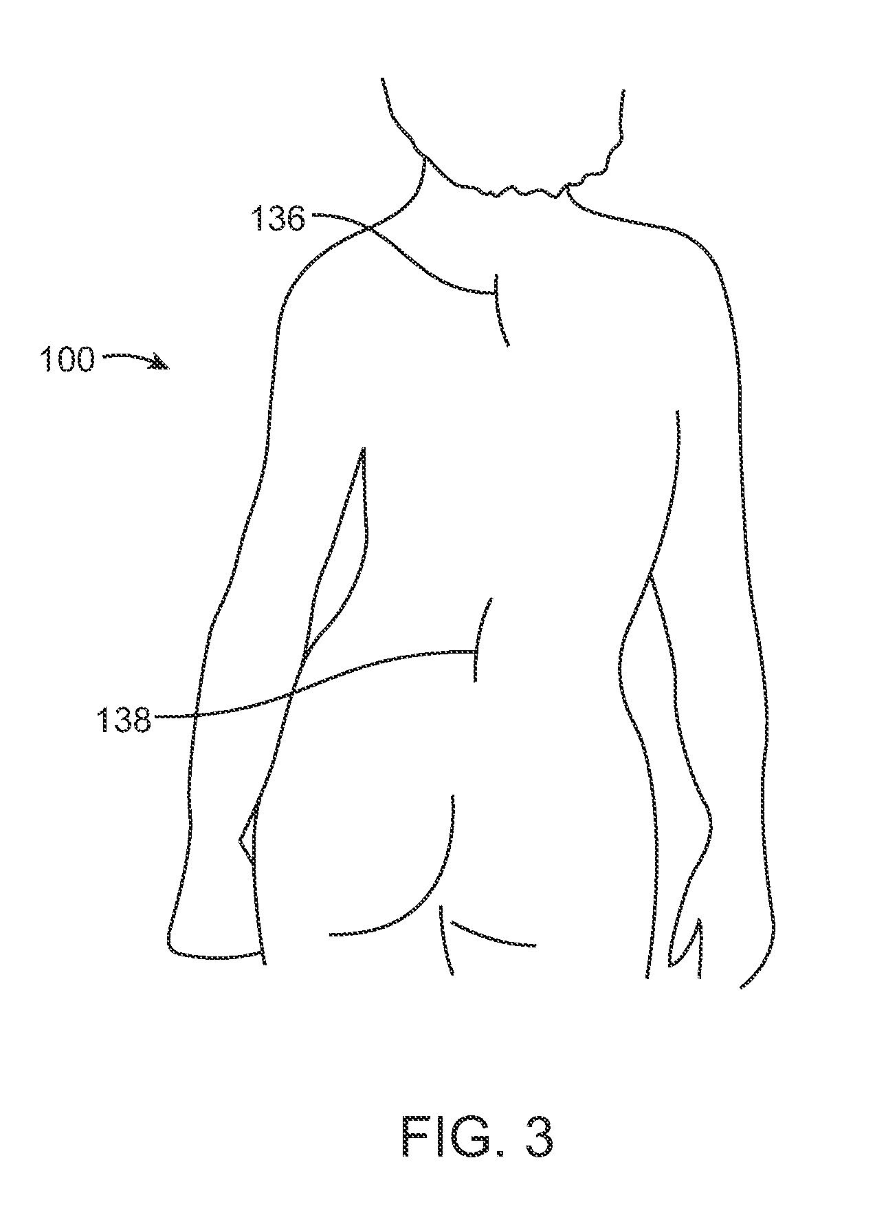
FIG. 3 illustrates the small incisions made during scoliosis non-fusion surgery of the inventive embodiments.
FIG. 4 illustrates an exemplary distraction device mounted on the spine of a subject.
FIG. 5A is a cross-sectional view of a distraction rod and adjustable portion taken along a perpendicular axis to the longitudinal axis of the distraction rod.
FIG. 5B illustrates a cross-sectional view of the distraction rod and the adjustable portion taken along the line B'-B of FIG. 5A.
FIG. 5C illustrates an enlarged cross-sectional view of detail C of FIG. 5B.
FIG. 5D Illustrates a cross-sectional view of the magnet portion of the device, taken along the line D-D' of FIG. 5C.
FIG. 6 illustrates a distraction device being tested within a distraction loss tester.
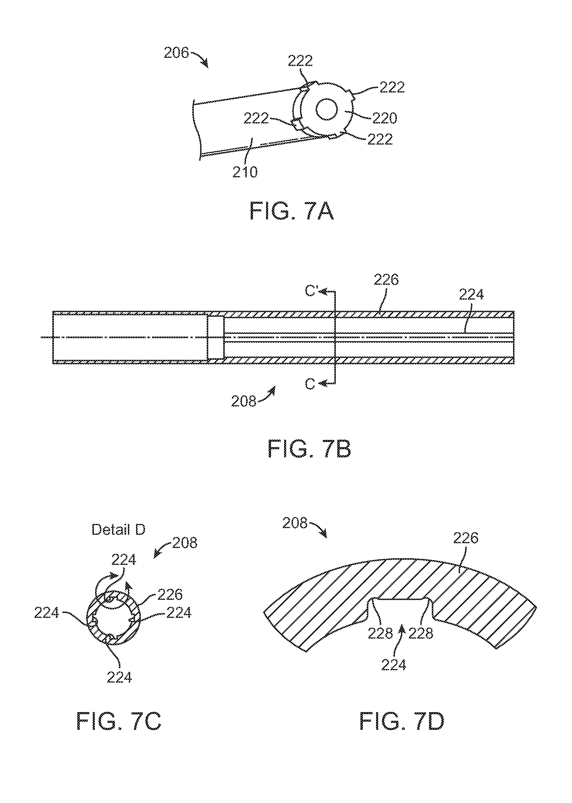
FIG. 7A illustrates a perspective view of one end of a distraction rod illustrating the splined tip.
FIG. 7B is a side cross-sectional view of the tubular housing with the lead screw and magnetic assembly removed for clarity.
FIG. 7C is a cross-sectional view of the tubular housing taken along the line C'-C in FIG. 7B.
FIG. 7D illustrates a magnified view of detail D of FIG. 7C.
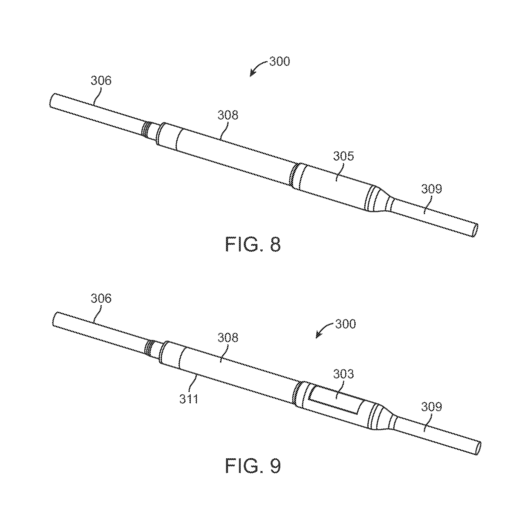
FIG. 8 illustrates an embodiment of a distraction device having a maintenance member.
FIG. 9 illustrates an embodiment of the distraction device of FIG. 8 with a cover sleeve removed and showing the maintenance member.
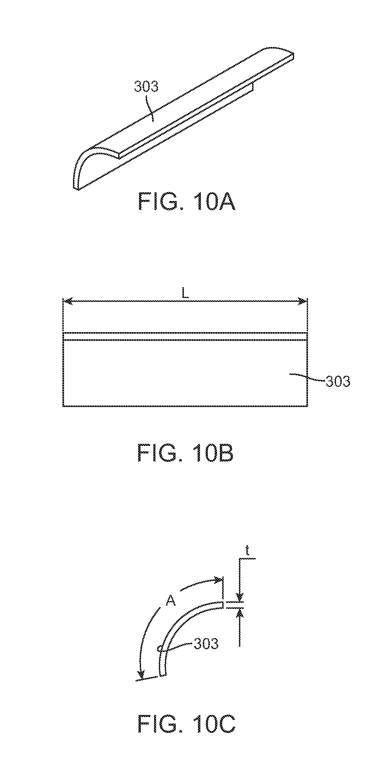
FIG. 10A illustrates the maintenance member of FIGS. 8 and 9.
FIG. 10B illustrates a side view of the maintenance member of FIG. 10A.
FIG. 10C illustrates an end view of the maintenance member of FIG. 10A.
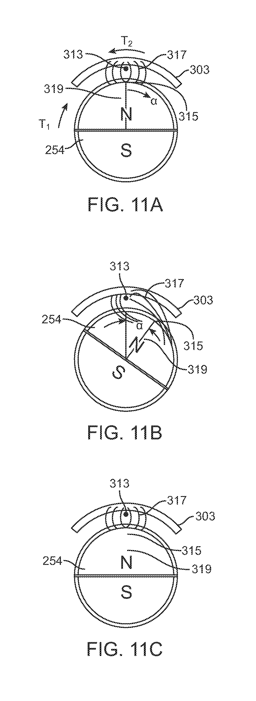
FIG. 11A illustrates the magnetic and mechanical forces acting on a cylindrical magnet.
FIG. 11B illustrates the cylindrical magnet being torqued to a finite amount away from its magnetic orientation with a maintenance member.
FIG. 11C illustrates the cylindrical magnet after being aligned from a torque applied on its north pole by a maintenance member.
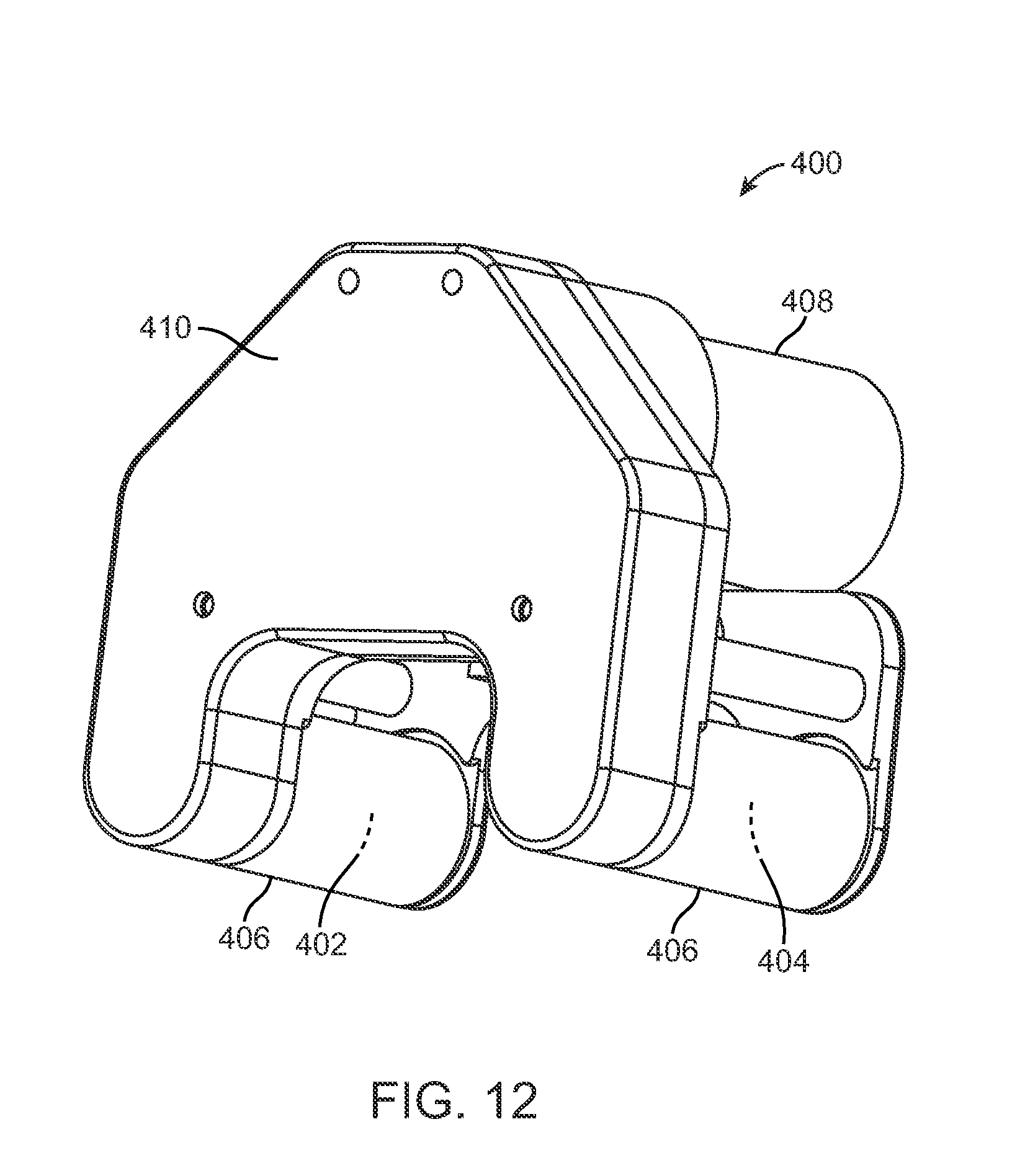
FIG. 12 illustrates and external adjustment device that is used with the distraction devices described herein.
FIG. 13 illustrates a method of using a magnetic compass to locate an implanted magnet with the magnetic compass in an initial location.
FIG. 14 illustrates a method of using a magnetic compass to locate an implanted magnet with the magnetic compass in a final location.
DETAILED DESCRIPTION OF THE ILLUSTRATED EMBODIMENTS
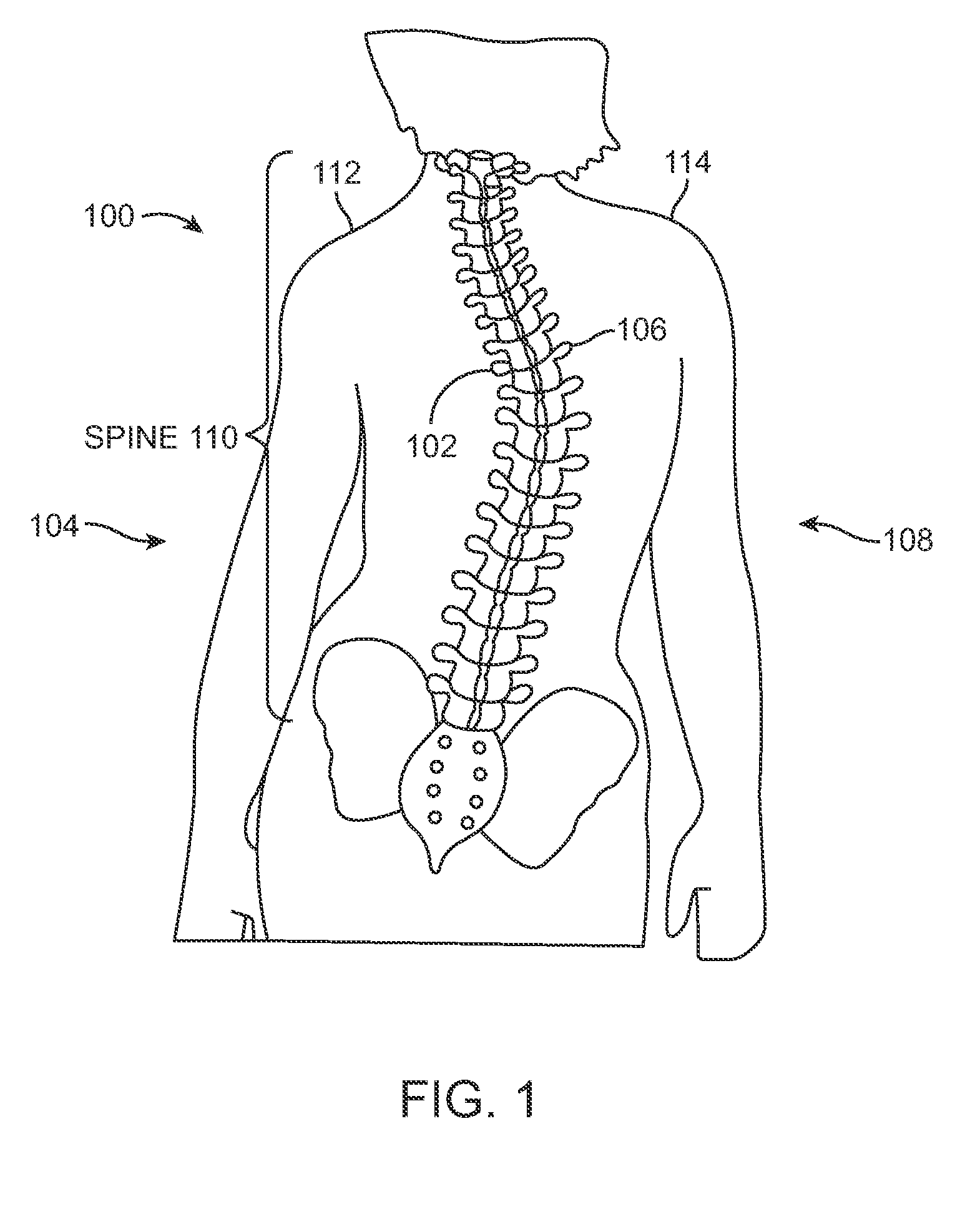
FIG. 1 illustrates a patient 100 with scoliosis. The concave portion 102 of the spinal curve can be seen on the left side 104 of the patient 100, and the convex portion 106 can be seen on the right side 108 of the patient 100. Of course, in other patients, the concave portion 102 may appear on the right side 108 of the patient 100 while the convex portion 106 may be found on the left side 104 of the patient. In addition, as seen in FIG. 1, some rotation of the spine 110 is present, and unevenness between the left shoulder 112 and right shoulder 114 is seen.
FIG. 2 illustrates the Cobb angle 116 of a spine 110 of a patient with scoliosis. To determine the Cobb angle, lines 118 and 120 are drawn from vertebra 122 and 124, respectively, intersecting perpendicular lines 126 and 128 are drawn by creating 90.degree. angles 130 and 132 from lines 118 and 120. The angle 116 created from the crossing of the perpendicular lines 126 and 128 is defined as the Cobb angle. In a perfectly straight spine, this angle is 0.degree..
In many Adolescent Idiopathic Scoliosis (AIS) patients with a Cobb angle of 40.degree. or greater, spinal fusion surgery is typically the first option. Alternatively, non-fusion surgery may be performed, for example with the distraction device 200 of FIG. 4. FIG. 3 illustrates an upper incision 136 and a lower incision 138 formed in the patient 100 which is typically made during non-fusion scoliosis surgery.
FIG. 4 illustrates a distraction device 200 for treating scoliosis according to one embodiment of the invention. The distraction device 200, which is an implantable device, is fixated at its upper end 202 and lower end 204 to the patient's spine 500. The illustrated example of the spine 500 includes the particular thoracic and lumbar vertebrae that typically encompass a scoliotic curve, for example the curve of a patient with adolescent idiopathic scoliosis. The T3 through T12 thoracic vertebrae, 503, 504, 505, 506, 507, 508, 509, 510, 511, 512, respectively and the L1 through L3 vertebrae, 513, 514, 515 are depicted in FIG. 4, not in a severe scoliotic condition, but in a very slight residual curve that represents a modest curve that has been partially or completely straightened during the implantation procedure.
Each vertebra is different from the other vertebra by its size and shape, with the upper vertebra generally being smaller than the lower vertebra. However, generally, the vertebrae have a similar structure and include a vertebral body 516, a spinous process 518, 520, laminae 526, transverse processes 521, 522 and pedicles 524. In this embodiment, the distraction device 200 includes a distraction rod 206 which is adjustable (lengthwise) via a coupled adjustable portion 208. The distraction device 200 also includes a lower short rod 209. The distraction device 200 is fixated to the spine 500 via hooks 600, 601 at the upper end 202 of the distraction rod 206. Alternatively, a clamp may be secured around an adjacent rib (not shown) or rib facet. In still another alternative, a pedicle screw system may be used.
Referring hack to FIG. 4, the distraction device 200 is illustrated as being fixated to the spine 500 with a pedicle screw system 531, which attaches directly to the lower short rod 209. The distraction rod 206 is shown after it has been bent into a kyphotic curve, and the lower short rod is shown after it has been bent into a lordotic curve. As explained in more detail below. The adjustable portion 208 preferably contains a magnetic assembly having a permanent magnet configured to drive a lead screw that, depending on the direction of rotation of the internal magnet, will extend or retract the distraction rod 206 using the adjustable portion 208. Lengthening of the distraction rod 206, for example, will impart a distraction force to the spine 500. Retracting the distraction rod 206 will lower or remove the distraction force on the spine 500, for example if too high a distraction force causes pain or complications.
Because a scoliotic spine is also rotated (usually the center section is rotated to the right in AIS patients), the non-fusion embodiment presented here allows de-rotation of the spine 500 to happen naturally, because there is no fixation at the middle portion of the distraction device 209.
In order to further facilitate this de-rotation, the distraction device 200 may allow for free rotation at its ends. For example, the adjustable portion 208 may be coupled to the spine via an articulating joint. U.S. Patent Application Publication Nos. 20090112207 and 20100094302, both of which are incorporated by reference, describe various articulating interlaces and joints that may be utilized to couple the adjustable portion 208 to the connecting rods or the like. These Publications further describe various distraction rod embodiments and methods of use that may be used with inventions described herein.
As noted, the distraction rod 206 and the lower short rod 209 may be bent by the user (or supplied pre-curved) with the typical shape of a normal saggital spine, but it should also be noted that the curve may be slightly different than standard scoliosis fission instrumentation, because in the non-fusion embodiment described herein, the distraction device 200 is not usually flush with the spine but rather is placed either subcutaneous or sub-fascial, and thus is not completely below the back muscles. In these less invasive methods, the only portions of the distraction device 200 that are designed to be placed below the muscles are the hooks 600, 601 and the portion of the distraction rod 206 immediately adjacent the hooks 600, 601, the pedicle screw system 531 and the lower short rod 209. Thus, FIG. 4 illustrates an embodiment in which the bulk of the hardware associated with the distraction device 200 is placed over the muscle. It should be understood, however, that in alternative configurations, any other part of the entire implantable embodiment may be placed under the muscle (i.e., sub-muscular). It should be appreciated that a much smaller amount of muscle needs to be dissected during the procedure in comparison with current fusion procedures. This will allow for a much shorter procedure, much less blood loss, much quicker recovery, and less time in the hospital/less risk of infection.
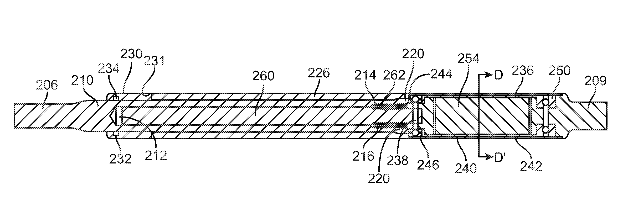
FIGS. 5A-5C illustrate cross-sectional views of the interface of the distraction rod 206 with the adjustable portion 208. FIG. 5A is a cross-sectional view of the distraction rod 206 and adjustable portion 208 taken along a perpendicular axis to the longitudinal axis of the distraction rod 206. FIG. 5B illustrates a cross-sectional view of the distraction rod 206 and the adjustable portion 208 taken along the line B'-B of FIG. 5A. FIG. 5C illustrates an enlarged cross-sectional view of detail C of FIG. 5B. As best seen in FIG. 5C, an end 210 of the distraction rod 206 includes an elongate recess 212. The elongate recess 212 may have a length of around 60 mm. The recess 212 is dimensioned to receive a lead screw 260. The lead screw 260 may be made from a high strength material such as, for example, titanium. At least a portion of the lead screw 260 includes external threads 262 that are configured to engage with a nut 214 integrated into the recess 212. The nut 214 provides a threaded portion on the recess 212 of the distraction rod 206. The lead screw 260 may have, for example, 80 threads per inch although more or less could be used. The nut 214 may includes threads or a chamfered surface 216 on the outer diameter in order to better ensure a secure attachment to the inner diameter of the recess 212 of the distraction rod 206. For example, the nut 214 may be bonded to the distraction rod 206 using an adhesive such as EPOTEK 353ND, available from EPOXY TECHNOLOGY, INC., 14 Fortune Drive, Billerica, Mass. This allows the distraction rod 206 to be fabricated from a single piece of stronger material. It also provides for clearance between the lead screw 260 and internal diameter of the distraction rod 206. Alternatively, a threaded portion may be directly formed in the recess 212 without the aid of a separate nut 214. A radially-poled cylindrical magnet 254 is part of a magnetic assembly 236 comprising a first cup 240 and a second cup 242. The first and second cups 240, 242 are made from titanium. This entire magnetic assembly 236 is attached to the lead screw 260, for example by a high strength pin 238 which is placed through a hole in the lead screw 260 and a receptacle 244 in the first cup 240. This couples the cylindrical magnet 254 to die lead screw 260. The cylindrical magnet 254 typically has two poles, a North and a South that are radially arrayed, as depicted in FIG. 5D. The cylindrical magnet may comprise a rare earth material, such as Neodymium-Iron-Boron. The cylindrical magnet 254 is attached to a thrust bearing 250 and a radial bearing 246, which allow the low friction rotation of the cylindrical magnet 254, and this aids the low friction rotation of the lead screw 260 within the nut 214. This allows for the non-invasive coupling of an external moving magnetic field, in order to non-invasively distract the distraction device 200, allowing the distraction rod 206 to telescopically extend from the adjustable portion 208, and impart an increased distraction force on the spine 500. The moving magnetic held may be supplied by one or more rotating magnets, for example as part of a motor-driven external device. Alternatively, the moving magnetic field may be produced by an electromagnetic coil. The lead screw 260 and nut 214 combination allows for a device that can be distracted or retracted. The device is retracted by making the external moving magnetic field move in the opposite rotational direction. This is an advantage, for example in the case of a patient that has accidentally been over distracted. The distraction device 200 may then be retracted somewhat, until the patient is at the preferred distraction amount. An elastomeric o-ring 234 creates a dynamic seal between the inner surface of the adjustable portion 208 and the distraction rod 206. This o-ring resides inside a recess 232 of an o-ring gland 230 within the interior of the adjustable portion 208.
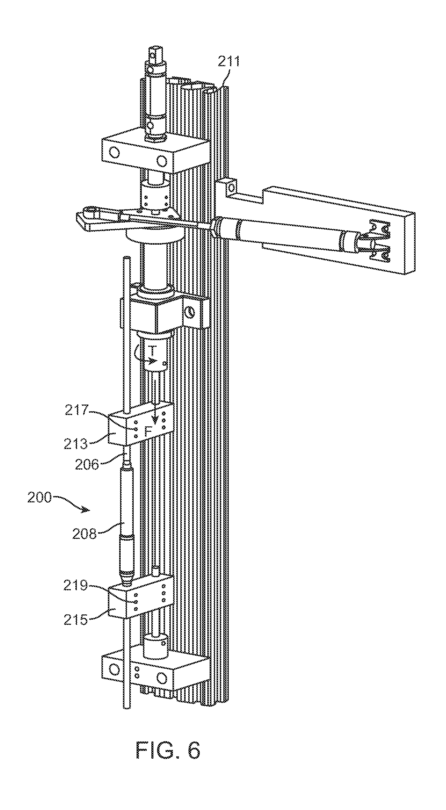
The low friction lead screw 260 and nut 214 combination combined with the low friction bearings 250, 246 minimize the torque that needs to be applied on the cylindrical magnet 254. Thus, they also minimize the required size of the cylindrical magnet 254, because they minimize the magnetic force required to make the cylindrical magnet 254 turn. However, these same advantages also may make the assembly prone to lose some of the distraction length as the patient moves through daily activity. For example (returning to FIG. 4), it may be possible for a patient's movement to create a "screw-like" motion which is capable of slowly retracting the distraction rod 206 in relation to the adjustable portion 208, and thus shortening the distraction device 200 by multiples of very small movement. For example, in the process of walking, running, bending or other movements, a patient may place a compressive bending force (F) on the distraction device 200. In these movements, the patient may also place a torque (T) between the two ends of the distraction device 200, for example, the two ends at the portions that are secured to the spine 500. In FIG. 4, a positive value of torque (T) denotes a right-hand mode, in which the distraction rod 206 is given energy to move in the direction of the arrow at torque (T) while the adjustable portion is given energy to move in the opposite circumferential direction. A negative value of torque (T) would represent the opposite, left hand motion. If there are no internal features in the distraction device 200 to limit the circumferential motion of the distraction rod 206 in relation to the adjustable portion 208, the a positive value of torque (T) will cause the distraction rod 206 and adjustable portion 208 to circumferentially displace until, for example, the torsional movement in the patient stops, either willingly, or by the physical limitations in the spine or the rest of body. If the patient's movements cycle between bending and twisting, and therefore, between the force (F) and torque (T) depleted, they may do so in such a way as to cause a multiplicity of slight angular turns of the lead screw 260 in one direction in relation to the nut 214, without compensatory turns in the opposite direction. For example, referring to FIG. 6, in laboratory testing, a distraction device 200 was secured with set screws 217, 219 in a distraction loss tester 211 having simulated vertebrae 213, 215 in order to place controlled axial compressive force (F) and a controlled twisting torque (T) on the distraction device 200. One cycle of the program consisted of a 100 Newton compressive force (F), followed by a 0.81 Newton-meter torque (T), after which the compressive force (F) was completely released (0 Newton) and then an opposite torque (-0.81 Newton-meter) (-T) was placed. These parameters are considered extreme in relation to a typical patient's movements, but are effective in estimating "worst-case" operation, for example, if the distraction device 200 were being used as a single device within a very active patient. A distracted distraction device 200 tested under these parameters was able to lose several mm of distraction length after about 10,000 cycles, which is estimated be the equivalent of about one week in a patient (though actual patient movements are usually much more variable).
In reality, the preferred design for a distraction device 200, does not allow significant circumferential motion between the distraction rod 206 and the adjustable portion 208. FIG. 7A illustrates a perspective view of the splined tip 220 of the distraction rod 206. The splined tip 220 is illustrated with four (4) protrusions 222 that interface with four (4) corresponding longitudinal grooves 224 (two pairs in symmetric opposition) formed inside a tubular housing 226 (illustrated in FIGS. 7B-D) of adjustable portion 208. The longitudinal grooves 224 may be formed by wire EDM machining or by broaching. While FIGS. 7A-7D illustrate an embodiment that uses four (4) protrusions 222 along with four (4) longitudinal grooves 224 there may be more or fewer. The tight tolerance of the splined tip 220 with the longitudinal grooves 224 keeps the distraction rod 206 centered within the tubular housing 226. In addition, the combination of the splined tip 220 and corresponding grooves 224 act as an anti-rotation feature that prevents the distraction rod 206 from rotating relative to the tubular housing 226. This may be necessary to allow the distraction device 200 to be "rigidized" in the event the device is used in fusion applications, instead of the non-fusion applications described, for example, in a fusion application, it is desired that the spine 500 not be able to flex or rotate much during the months that the fusion is taking place. In either the fusion applications or the non-fusion applications, the anti-rotation features are intended to limit inadvertent extension, and/or retraction, of the distraction rod 206 resulting from, for instance, patient movements.
FIG. 7C is a cross-sectional view of the tubular housing 226 taken along the line C'-C in FIG. 7B. FIG. 7D illustrates a magnified view of detail D of FIG. 7C. In this illustrated embodiment, as best seen in the detailed view of FIG. 7D, small reliefs 228 are incorporated into the sides or corners of the longitudinal grooves 224. These reliefs 228 may be slight over cut wire EDM notches that prevent the corners of the protrusions 222 from contacting the inner wall of the tubular housing 226. Less contact between the protrusions 222 and the longitudinal grooves 224 results in less frictional forces and reduces the likelihood of binding. Optionally, the tops of the protrusions 222 could be curved, for example, cut from a diameter instead of a square. This rounding of the protrusions 222 would keep the protrusions 222 from binding with the longitudinal grooves 224 when torsional stresses are imparted between the distraction rod 206 and the adjustable portion 208. This optional modification makes the distraction rod 206 easier to manufacture and eliminates the need for the relief 228 overcuts. At the maximum amount of axial distraction length, the protrusions 222 butt up against a stop 231 (as seen in FIG. 5C), so that the distraction rod 206 terminates its axial movement in relation to the adjustable portion 208.
The anti-rotation features of FIGS. 7A-7D are effective in severely minimizing distraction loss in a large variety of patient applications, however, under severe conditions, such as those described in FIG. 6, a distraction device 200 with these features may still lose as much as 1 mm over 10,000 cycles. An additional design improvement which takes advantage of the magnetic poles (FIG. 5D) of cylindrical magnet 254 will now be described, as a way to severely limit distraction loss, even in the most severe performance conditions.
FIG. 8 is a view of a distraction device 300 which does not allow distraction loss when subjected to the severe testing parameters described above. Distraction device 300 has distraction rod 306 and adjustable portion 308, and the device is identical to the distraction device 200 described in the prior figures, except that it also comprises a maintenance member 303 as seen in FIG. 9. A lower short rod 309 extends from the adjustable portion 308 in a direction opposite the distraction rod 306. FIG. 9 shows the maintenance member 303 with external cover 305 removed. FIG. 8 shows the completed device with the maintenance member 303 completely covered by external cover 305. The external cover 305 is made of Titanium or Titanium alloy, for example, and is welded to the exterior of the adjustable portion 308 (also Titanium or titanium alloy) to completely isolate maintenance member 303 from the patient. The maintenance member 303 is made from a magnetically permeable material such as iron or mu-metal (75% nickel, 15% iron, plus copper and molybdenum). The maintenance member may also be made from a biocompatible and typical implant material, such as 400 series stainless steel, for example 420 stainless steel. Alternatively to being isolated within the double wall of the adjustable portion 308 of the distraction device 300 as depicted, a portion of the outer wall of the adjustable portion 308 may be made from a magnetically permeable material, such as 400 series stainless steel and the remainder of the outer wall may be made of a material like Titanium, or Titanium alloy, without significant magnetic properties. The maintenance member 303 may also be coated with a biocompatible material. As illustrated in FIGS. 10A, 10B and 10C, the maintenance member 303 has an arcuate shape with an arc of less than 360.degree.. In some embodiments, the are may be less than 180.degree. or 120.degree.. In the embodiment of FIGS. 10A, 10B and 10C, the arc (A) is approximately 99.degree. although a smaller am may be used. The length (L) of the maintenance member 303 is 19 mm in the embodiment depicted. In the adjustable portion 308 of the distraction device 300, the maintenance member 303 is located axially in the same portion as the cylindrical magnet 254. Because of its magnetically permeable characteristics, the maintenance member 303 will most strongly attract the north pole or the south pole of the cylindrical magnet 254, but will not attract the portion which is halfway between the north, pole and south pole. Referring to FIG. 10C, the maintenance member 303 preferably has a thickness (t) of at least 0.2 mm, and more preferably at least 0.3 mm. A typical thickness of the maintenance member 303 is 0.48 mm (0.019 inches) or less. In the configuration depicted, the radius of curvature of the concave surface of the maintenance member 303 is 4.5 mm but this thickness could be less. The diameter of the adjustable portion 308 is 10.5 mm over the external cover 305, and is 9.0 mm over the non-magnetic portion 311.
FIGS. 11A, 11B and 11C demonstrate the effect of the maintenance member 303 in maintaining the circumferential orientation of the cylindrical magnet 254, and thus the circumferential orientation of the lead screw 260 (FIG. 5C), and thus the amount of axial distraction in the distraction device 300. In FIG. 11A, the centerpoint 315 of the north pole 319 of the cylindrical magnet 254 aligns with the center of mass 313 of the maintenance member 303. When patient movement causes a first torque T1 to be applied to the cylindrical magnet 254, a magnetic corrective torque T2 based on the magnetic field 317 between the maintenance member 303 and the cylindrical magnet 254 acts upon the cylindrical magnet 254. If the first torque T1 is less than the corrective torque T2, then the magnet will not be displaced. It should be noted however that the corrective torque T2 increases as the displacement angle .alpha. increases. When a significantly large torque is placed on the cylindrical magnet 254 (FIG. 11B), for example in combination with a significant compressive force on the distraction device 300, the lead screw will slightly turn, and thus the magnet will slightly turn. Because the maintenance member 303 is present, the magnetic field 317 will return the cylindrical magnet 254 to its original circumferential orientation (FIG. 11C), for example when the compressive force on the distraction device 300 is released.
It should be noted that the distraction force which can be achieved in the distraction device 300 will be somewhat less with the maintenance member 303 in place than without it. For example, a distraction device 300 that achieves a distraction force of 220 Newtons without the maintenance member 303 will achieve a distraction force of about 195 Newtons (12% reduction) with the maintenance member 303 in place. The circumferential orientation of the distraction device 300, and thus the circumferential orientation of the maintenance member 303 within the body, does not cause a large difference in the ability to distract the distraction device 300, because typically very large, overpowering magnets are used externally to distract the implanted distraction device 300. Typically, two such magnets are located in an external adjustment device and are rotated to impart rotational motion to the cylindrical magnet 254. Particular details on the nature of the external adjustment devices that can be used in connection with the distraction devices described herein are disclosed, for example, in U.S. Patent Application Publication Nos. 2009/0112207, 2010/0094302, 2010/0121323, and U.S. patent application Ser. No. 13/172,598, all of which are incorporated by reference herein. FIG. 12 illustrates an external adjustment device 400 according to one embodiment that includes two permanent magnets 402, 404 contained within respective covers 406. Each permanent magnet 402, 404 is rotatable within its respective cover 406 and provides a moving magnetic field. A motor 408 is mechanically engaged to the permanent magnets 402, 404 via a transmission (not shown) contained within a housing 410 of the external adjustment device 400
Distraction devices constructed with the maintenance member 303 as described, having a cylindrical magnet 254 diameter of less than 9 mm, have been tested in the severe 100 Newton, compressive force/0.81 Newton-meter torque cyclic regime as described, and have maintained their distraction amount over hundreds of thousands of cycles. These devices have also been implanted in patients who are physically active, and the implanted devices have maintained their distraction amount over several months of patient activity.
Another advantage of the maintenance member 303 is that, when distracting the distraction device, the device is adjusted to very specific gradations. For example two per rotation of the magnet, when either the south pole or the north pole aligns with the center of mass 313 of the maintenance member 303. For example, these gradations may be equal to approximately 0.16 mm in the present case, or even more preferably 0.10 mm or 0.20 mm.
In one alternative embodiment, there are two or more magnetic members 303, for example, one magnetic member matched with each of the poles of the cylindrical magnet. In another alternative embodiment, the cylindrical magnet may be replaced by two or more magnetically permeable components, each spanning less than 180.degree. of an arc, and the maintenance member may be replaced with a magnet. The maintenance member may include a number of configurations including a plate, a wire, a series of balls, or any other configuration of magnetically permeable material.
FIGS. 13 and 14 describe a method for locating an implanted magnet 702 within a patient 700. This can be used for any magnetic medical device, but will be described specifically for a distraction system containing a magnet. The method utilizes standard magnetic compasses, which can be obtained very easily all over the world. The method consists of providing a magnetic compass 704, providing instructions for a user for using the magnetic compass 704 to locate au implanted magnet 702 within the distraction system, wherein the instructions instruct the user to place the magnetic compass 704 in proximity to a general area 708 of the patient's skin, near the expected location of the implanted magnet 702 of the distraction system, and for the user to view the direction that a magnetized pointer 706 of a needle 705 of the magnetic compass 704 points, and for the user to determine that the magnetized pointer 706 is pointing towards the implanted magnet 702, wherein the instructions further instruct the user to move the magnetic compass 704 along the skin of the patient until the magnetized pointer 706 is perpendicular to the skin (FIG. 14), and for the user to determine that the location 710 to which the magnetic compass 704 is moved is the correct location for placing an external adjustment device 400 which is enabled to cause the distraction system to magnetically distract.
As illustrated in FIGS. 13, and 14, the patient 700 has an implanted magnet 702 which is implanted near the lower back area, and the patient lies prone while the magnetic compass 704 is held to the side of the patient, with the needle 705 able to spin on the horizontal plane, and with the magnetic compass 704 held at approximately the same horizontal plane as the depth of implantation of the implanted magnet 702. In FIG. 13, the magnetic compass 704 is initially held further distal (towards the feet) than the implanted magnet 702, with the magnetized pointer 706 of the needle 705 pointing at an angle towards the implanted magnet 702. The magnetic compass 704 is moved in direction (D) until it is located as in FIG. 14, with the magnetized pointer 706 of the needle 705 perpendicular to the skin. Using the method described, small implanted magnets may be successfully located. For example, the location of a magnet having a mass of 5.4 grams can be correctly identified with a standard low-cost magnetic compass at an implant depth of as much as 10 cm.
While embodiments have been shown and described, various modifications may be made without departing from the scope of the inventive concepts disclosed herein. The invention(s), therefore, should not be limited, except to the following claims, and their equivalents.
* * * * *
D00000
D00001
D00002
D00003
D00004
D00005
D00006
D00007
D00008
D00009
D00010
D00011
D00012
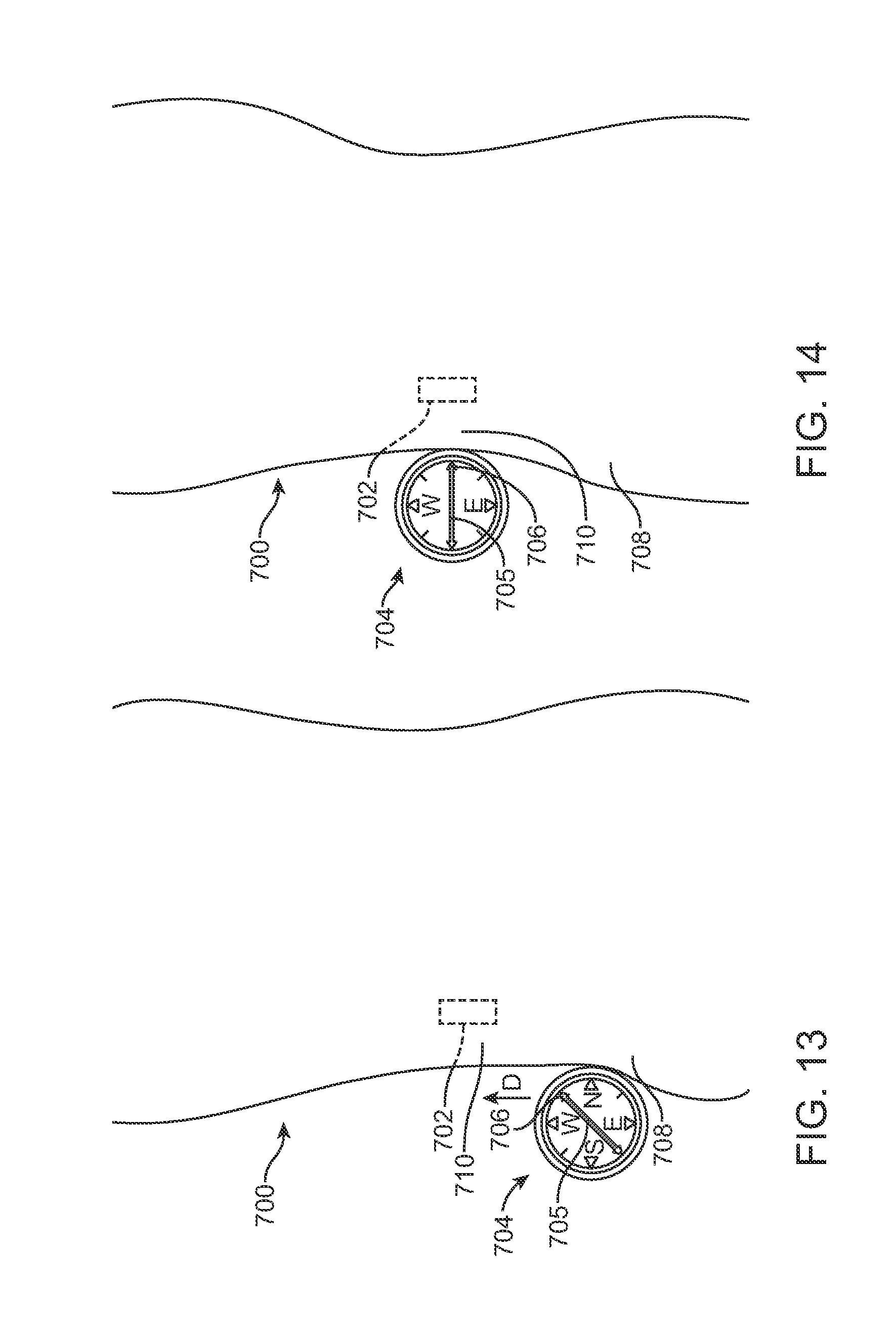
XML
uspto.report is an independent third-party trademark research tool that is not affiliated, endorsed, or sponsored by the United States Patent and Trademark Office (USPTO) or any other governmental organization. The information provided by uspto.report is based on publicly available data at the time of writing and is intended for informational purposes only.
While we strive to provide accurate and up-to-date information, we do not guarantee the accuracy, completeness, reliability, or suitability of the information displayed on this site. The use of this site is at your own risk. Any reliance you place on such information is therefore strictly at your own risk.
All official trademark data, including owner information, should be verified by visiting the official USPTO website at www.uspto.gov. This site is not intended to replace professional legal advice and should not be used as a substitute for consulting with a legal professional who is knowledgeable about trademark law.