Steering compensation with grip sensing
Chandy Sep
U.S. patent number 10,399,591 [Application Number 15/283,628] was granted by the patent office on 2019-09-03 for steering compensation with grip sensing. This patent grant is currently assigned to Steering Solutions IP Holding Corporation. The grantee listed for this patent is Steering Solutions IP Holding Corporation. Invention is credited to Ashok Chandy.


| United States Patent | 10,399,591 |
| Chandy | September 3, 2019 |
Steering compensation with grip sensing
Abstract
A system for grip-based handwheel compensation includes a net handwheel torque moment determination module that determines a net handwheel torque moment between a left grip and a right grip on a handwheel. The system also includes a filter transition compensation module that applies a filter to smooth transitions in the net handwheel torque moment as a bias compensation. The system further includes a handwheel torque compensation module that determines a grip compensated handwheel torque based on a difference between a sensed handwheel torque and the bias compensation.
| Inventors: | Chandy; Ashok (Palo Alto, CA) | ||||||||||
|---|---|---|---|---|---|---|---|---|---|---|---|
| Applicant: |
|
||||||||||
| Assignee: | Steering Solutions IP Holding
Corporation (Saginaw, MI) |
||||||||||
| Family ID: | 61623407 | ||||||||||
| Appl. No.: | 15/283,628 | ||||||||||
| Filed: | October 3, 2016 |
Prior Publication Data
| Document Identifier | Publication Date | |
|---|---|---|
| US 20180093700 A1 | Apr 5, 2018 | |
| Current U.S. Class: | 1/1 |
| Current CPC Class: | B62D 6/10 (20130101); B62D 5/0463 (20130101); B62D 1/043 (20130101) |
| Current International Class: | B62D 1/04 (20060101); B62D 5/04 (20060101); B62D 6/10 (20060101) |
References Cited [Referenced By]
U.S. Patent Documents
| 4315117 | February 1982 | Kokubo et al. |
| 4337967 | July 1982 | Yoshida et al. |
| 4503300 | March 1985 | Lane, Jr. |
| 4503504 | March 1985 | Suzumura et al. |
| 4561323 | December 1985 | Stromberg |
| 4691587 | September 1987 | Farrand et al. |
| 4836566 | June 1989 | Birsching |
| 4921066 | May 1990 | Conley |
| 4962570 | October 1990 | Hosaka et al. |
| 4967618 | November 1990 | Matsumoto et al. |
| 4976239 | December 1990 | Hosaka |
| 5240284 | August 1993 | Takada et al. |
| 5295712 | March 1994 | Omura |
| 5319803 | June 1994 | Allen |
| 5469356 | November 1995 | Hawkins et al. |
| 5488555 | January 1996 | Asgari et al. |
| 5618058 | April 1997 | Byon |
| 5668721 | September 1997 | Chandy |
| 5690362 | November 1997 | Peitsmeier et al. |
| 5765116 | June 1998 | Wilson-Jones et al. |
| 5893580 | April 1999 | Hoagland et al. |
| 5911789 | June 1999 | Keipert et al. |
| 6070686 | June 2000 | Pollmann |
| 6138788 | October 2000 | Bohner et al. |
| 6170862 | January 2001 | Hoagland et al. |
| 6212453 | April 2001 | Kawagoe et al. |
| 6227571 | May 2001 | Sheng et al. |
| 6256561 | July 2001 | Asanuma |
| 6301534 | October 2001 | McDermott, Jr. et al. |
| 6354622 | March 2002 | Ulbrich et al. |
| 6360149 | March 2002 | Kwon et al. |
| 6373472 | April 2002 | Palalau et al. |
| 6381526 | April 2002 | Higashi et al. |
| 6390505 | May 2002 | Wilson |
| 6481526 | November 2002 | Millsap et al. |
| 6575263 | June 2003 | Hjelsand et al. |
| 6578449 | June 2003 | Anspaugh et al. |
| 6598695 | July 2003 | Menjak et al. |
| 6611745 | August 2003 | Paul |
| 6612392 | September 2003 | Park et al. |
| 6612393 | September 2003 | Bohner et al. |
| 6778890 | August 2004 | Shimakage et al. |
| 6799654 | October 2004 | Menjak et al. |
| 6817437 | November 2004 | Magnus et al. |
| 6819990 | November 2004 | Ichinose |
| 6820713 | November 2004 | Menjak et al. |
| 6889792 | May 2005 | Fardoun et al. |
| 7021416 | April 2006 | Kapaan et al. |
| 7048305 | May 2006 | Muller |
| 7062365 | June 2006 | Pei |
| 7295904 | November 2007 | Kanevsky et al. |
| 7308964 | December 2007 | Hara et al. |
| 7428944 | September 2008 | Gerum |
| 7461863 | December 2008 | Muller |
| 7495584 | February 2009 | Sorensen |
| 7628244 | December 2009 | Chino et al. |
| 7719431 | May 2010 | Bolourchi |
| 7735405 | June 2010 | Parks |
| 7793980 | September 2010 | Fong |
| 7862079 | January 2011 | Fukawatase et al. |
| 7894951 | February 2011 | Norris et al. |
| 7909361 | March 2011 | Oblizajek et al. |
| 8002075 | August 2011 | Markfort |
| 8027767 | September 2011 | Klein et al. |
| 8055409 | November 2011 | Tsuchiya |
| 8069745 | December 2011 | Strieter et al. |
| 8079312 | December 2011 | Long |
| 8146945 | April 2012 | Born et al. |
| 8150581 | April 2012 | Iwazaki et al. |
| 8170725 | May 2012 | Chin et al. |
| 8170751 | May 2012 | Lee et al. |
| 8260482 | September 2012 | Szybalski et al. |
| 8352110 | January 2013 | Szybalski et al. |
| 8374743 | February 2013 | Salinger |
| 8452492 | May 2013 | Buerkle et al. |
| 8479605 | July 2013 | Shavrnoch et al. |
| 8548667 | October 2013 | Kaufmann |
| 8606455 | December 2013 | Boehringer et al. |
| 8632096 | January 2014 | Quinn et al. |
| 8634980 | January 2014 | Urmson et al. |
| 8650982 | February 2014 | Matsuno et al. |
| 8670891 | March 2014 | Szybalski et al. |
| 8695750 | April 2014 | Hammond et al. |
| 8725230 | May 2014 | Lisseman et al. |
| 8798852 | August 2014 | Chen et al. |
| 8818608 | August 2014 | Cullinane et al. |
| 8825258 | September 2014 | Cullinane et al. |
| 8825261 | September 2014 | Szybalski et al. |
| 8843268 | September 2014 | Lathrop et al. |
| 8874301 | October 2014 | Rao et al. |
| 8880287 | November 2014 | Lee et al. |
| 8881861 | November 2014 | Tojo |
| 8899623 | December 2014 | Stadler et al. |
| 8909428 | December 2014 | Lombrozo |
| 8915164 | December 2014 | Moriyama |
| 8948993 | February 2015 | Schulman et al. |
| 8950543 | February 2015 | Heo et al. |
| 8994521 | March 2015 | Gazit |
| 9002563 | April 2015 | Green et al. |
| 9031729 | May 2015 | Lathrop et al. |
| 9032835 | May 2015 | Davies et al. |
| 9045078 | June 2015 | Tovar et al. |
| 9073574 | July 2015 | Cuddihy et al. |
| 9092093 | July 2015 | Jubner et al. |
| 9108584 | August 2015 | Rao et al. |
| 9134729 | September 2015 | Szybalski et al. |
| 9150200 | October 2015 | Urhahne |
| 9150224 | October 2015 | Yopp |
| 9159221 | October 2015 | Stantchev |
| 9164619 | October 2015 | Goodlein |
| 9174642 | November 2015 | Wimmer et al. |
| 9186994 | November 2015 | Okuyama et al. |
| 9193375 | November 2015 | Schramm et al. |
| 9199553 | December 2015 | Cuddihy et al. |
| 9207856 | December 2015 | Imai |
| 9227531 | January 2016 | Cuddihy et al. |
| 9233638 | January 2016 | Lisseman et al. |
| 9235111 | January 2016 | Davidsson et al. |
| 9235211 | January 2016 | Davidsson et al. |
| 9235987 | January 2016 | Green et al. |
| 9238409 | January 2016 | Lathrop et al. |
| 9248743 | February 2016 | Enthaler et al. |
| 9260130 | February 2016 | Mizuno |
| 9290174 | March 2016 | Zagorski |
| 9290201 | March 2016 | Lombrozo |
| 9298184 | March 2016 | Bartels et al. |
| 9308857 | April 2016 | Lisseman et al. |
| 9308891 | April 2016 | Cudak et al. |
| 9315210 | April 2016 | Sears et al. |
| 9333983 | May 2016 | Lathrop et al. |
| 9360865 | June 2016 | Yopp |
| 9714036 | July 2017 | Yamaoka et al. |
| 9725098 | August 2017 | Abou-Nasr et al. |
| 9810727 | November 2017 | Kandler et al. |
| 9845109 | December 2017 | George et al. |
| 9852752 | December 2017 | Chou et al. |
| 9868449 | January 2018 | Holz et al. |
| 10040330 | August 2018 | Anderson |
| 10137929 | November 2018 | Aoki et al. |
| 2002/0016661 | February 2002 | Frediani et al. |
| 2003/0046012 | March 2003 | Yamaguchi |
| 2003/0094330 | May 2003 | Boloorchi et al. |
| 2003/0227159 | December 2003 | Muller |
| 2004/0016588 | January 2004 | Vitale et al. |
| 2004/0046346 | March 2004 | Eki et al. |
| 2004/0099468 | May 2004 | Chernoff et al. |
| 2004/0129098 | July 2004 | Gayer et al. |
| 2004/0133330 | July 2004 | Ono et al. |
| 2004/0182640 | September 2004 | Katou |
| 2004/0204808 | October 2004 | Satoh et al. |
| 2004/0262063 | December 2004 | Kaufmann et al. |
| 2005/0001445 | January 2005 | Ercolano |
| 2005/0081675 | April 2005 | Oshita et al. |
| 2005/0155809 | July 2005 | Krzesicki et al. |
| 2005/0197746 | September 2005 | Pelchen et al. |
| 2005/0275205 | December 2005 | Ahnafield |
| 2006/0224287 | October 2006 | Izawa et al. |
| 2006/0244251 | November 2006 | Muller |
| 2006/0271348 | November 2006 | Rossow et al. |
| 2007/0021889 | January 2007 | Tsuchiya |
| 2007/0029771 | February 2007 | Haglund et al. |
| 2007/0046003 | March 2007 | Mori et al. |
| 2007/0046013 | March 2007 | Bito |
| 2007/0241548 | October 2007 | Fong |
| 2007/0284867 | December 2007 | Cymbal et al. |
| 2008/0009986 | January 2008 | Lu et al. |
| 2008/0238068 | October 2008 | Kumar et al. |
| 2009/0024278 | January 2009 | Kondo et al. |
| 2009/0189373 | July 2009 | Schramm et al. |
| 2009/0256342 | October 2009 | Cymbal et al. |
| 2009/0276111 | November 2009 | Wang et al. |
| 2009/0292466 | November 2009 | McCarthy et al. |
| 2010/0152952 | June 2010 | Lee et al. |
| 2010/0222976 | September 2010 | Haug |
| 2010/0228417 | September 2010 | Lee et al. |
| 2010/0228438 | September 2010 | Buerkle |
| 2010/0250081 | September 2010 | Kinser |
| 2010/0280713 | November 2010 | Stahlin et al. |
| 2010/0286869 | November 2010 | Katch et al. |
| 2010/0288567 | November 2010 | Bonne |
| 2011/0098922 | April 2011 | Ibrahim |
| 2011/0153160 | June 2011 | Hesseling et al. |
| 2011/0167940 | July 2011 | Shavrnoch et al. |
| 2011/0187518 | August 2011 | Strumolo et al. |
| 2011/0224876 | September 2011 | Paholics et al. |
| 2011/0266396 | November 2011 | Abildgaard et al. |
| 2011/0282550 | November 2011 | Tada et al. |
| 2012/0136540 | May 2012 | Miller |
| 2012/0150388 | June 2012 | Boissonnier et al. |
| 2012/0197496 | August 2012 | Limpibunterng et al. |
| 2012/0205183 | August 2012 | Rombold |
| 2012/0209473 | August 2012 | Birsching et al. |
| 2012/0215377 | August 2012 | Takemura et al. |
| 2013/0002416 | January 2013 | Gazit |
| 2013/0325202 | January 2013 | Howard et al. |
| 2013/0087006 | April 2013 | Luan |
| 2013/0158771 | June 2013 | Kaufmann |
| 2013/0218396 | August 2013 | Moshchuk |
| 2013/0233117 | September 2013 | Read et al. |
| 2013/0253765 | September 2013 | Bolourchi et al. |
| 2013/0292955 | November 2013 | Higgins et al. |
| 2014/0012469 | January 2014 | Kunihiro et al. |
| 2014/0028008 | January 2014 | Stadler et al. |
| 2014/0046542 | February 2014 | Kauffman et al. |
| 2014/0046547 | February 2014 | Kaufmann et al. |
| 2014/0111324 | April 2014 | Lisseman et al. |
| 2014/0152551 | June 2014 | Mueller et al. |
| 2014/0156107 | June 2014 | Karasawa et al. |
| 2014/0168061 | June 2014 | Kim |
| 2014/0172231 | June 2014 | Terada et al. |
| 2014/0277896 | September 2014 | Lathrop et al. |
| 2014/0277945 | September 2014 | Chandy |
| 2014/0300479 | October 2014 | Wolter et al. |
| 2014/0303827 | October 2014 | Dolgov et al. |
| 2014/0306799 | October 2014 | Ricci |
| 2014/0309816 | October 2014 | Stefan et al. |
| 2014/0354568 | December 2014 | Andrews et al. |
| 2015/0002404 | January 2015 | Hooton |
| 2015/0006033 | January 2015 | Sekiya |
| 2015/0014086 | January 2015 | Eisenbarth |
| 2015/0032322 | January 2015 | Wimmer |
| 2015/0032334 | January 2015 | Jang |
| 2015/0051780 | January 2015 | Hahne |
| 2015/0120142 | January 2015 | Park et al. |
| 2015/0060185 | March 2015 | Feguri |
| 2015/0120124 | April 2015 | Bartels et al. |
| 2015/0120141 | April 2015 | Lavoie et al. |
| 2015/0246673 | April 2015 | Tseng et al. |
| 2015/0123947 | May 2015 | Jubner et al. |
| 2015/0149035 | May 2015 | Enthaler et al. |
| 2015/0210273 | July 2015 | Kaufmann et al. |
| 2015/0251666 | July 2015 | Attard et al. |
| 2015/0283998 | September 2015 | Lind et al. |
| 2015/0324111 | September 2015 | Jubner et al. |
| 2015/0314804 | November 2015 | Aoki et al. |
| 2015/0338849 | November 2015 | Nemec et al. |
| 2016/0001781 | January 2016 | Fung et al. |
| 2016/0009332 | January 2016 | Sirbu |
| 2016/0071418 | March 2016 | Oshida et al. |
| 2016/0075371 | March 2016 | Varunjikar et al. |
| 2016/0082867 | March 2016 | Sugioka et al. |
| 2016/0200246 | March 2016 | Lisseman et al. |
| 2016/0185387 | June 2016 | Kuoch |
| 2016/0200343 | June 2016 | Lisseman et al. |
| 2016/0200344 | July 2016 | Sugioka et al. |
| 2016/0207536 | July 2016 | Yamaoka et al. |
| 2016/0207538 | July 2016 | Urano et al. |
| 2016/0209841 | July 2016 | Yamaoka et al. |
| 2016/0229450 | July 2016 | Basting et al. |
| 2016/0231743 | July 2016 | Bendewald et al. |
| 2016/0244070 | August 2016 | Bendewald et al. |
| 2016/0347347 | August 2016 | Lubischer |
| 2016/0347348 | August 2016 | Lubischer |
| 2016/0280251 | September 2016 | George et al. |
| 2016/0288825 | October 2016 | Varunjikar et al. |
| 2016/0291862 | October 2016 | Yaron et al. |
| 2016/0318540 | November 2016 | King |
| 2016/0318542 | November 2016 | Pattok et al. |
| 2016/0355207 | December 2016 | Urushibata |
| 2016/0362084 | December 2016 | Martin et al. |
| 2016/0362117 | December 2016 | Kaufmann et al. |
| 2016/0362126 | December 2016 | Lubischer |
| 2016/0364003 | December 2016 | O'Brien |
| 2016/0368522 | December 2016 | Lubischer |
| 2016/0375860 | December 2016 | Lubischer |
| 2016/0375923 | December 2016 | Schulz |
| 2016/0375925 | December 2016 | Lubischer et al. |
| 2016/0375926 | December 2016 | Lubischer et al. |
| 2016/0375927 | December 2016 | Schulz et al. |
| 2016/0375928 | December 2016 | Magnus |
| 2016/0375929 | December 2016 | Rouleau |
| 2016/0375931 | December 2016 | Lubischer |
| 2017/0029009 | February 2017 | Rouleau |
| 2017/0029018 | February 2017 | Lubischer |
| 2017/0066473 | March 2017 | Yu et al. |
| 2017/0101032 | April 2017 | Sugioka et al. |
| 2017/0101127 | April 2017 | Varunjikar et al. |
| 2017/0113712 | April 2017 | Watz |
| 2017/0151950 | June 2017 | Lien |
| 2017/0151977 | June 2017 | Varunjikar et al. |
| 2017/0151978 | June 2017 | Oya et al. |
| 2017/0158055 | June 2017 | Kim et al. |
| 2017/0158222 | June 2017 | Schulz et al. |
| 2017/0166222 | June 2017 | James |
| 2017/0203785 | July 2017 | Naik et al. |
| 2017/0225704 | August 2017 | Urushibata |
| 2017/0232998 | August 2017 | Ramanujam et al. |
| 2017/0240204 | August 2017 | Raad et al. |
| 2017/0242428 | August 2017 | Pal et al. |
| 2017/0293306 | October 2017 | Riefe et al. |
| 2017/0297606 | October 2017 | Kim et al. |
| 2017/0305425 | October 2017 | |
| 2017/0305458 | October 2017 | Wang et al. |
| 2017/0334458 | November 2017 | Sato et al. |
| 2018/0015948 | January 2018 | Varunjikar et al. |
| 2018/0017968 | January 2018 | Zhu et al. |
| 2018/0029632 | February 2018 | Bodtker |
| 2018/0059661 | March 2018 | Sato et al. |
| 2018/0059662 | March 2018 | Sato et al. |
| 2018/0072341 | March 2018 | Schulz et al. |
| 2018/0105198 | April 2018 | Bodtker et al. |
| 2018/0148087 | May 2018 | Wang et al. |
| 1722030 | Jan 2006 | CN | |||
| 1736786 | Feb 2006 | CN | |||
| 101037117 | Sep 2007 | CN | |||
| 101041355 | Sep 2007 | CN | |||
| 101596903 | Dec 2009 | CN | |||
| 102320324 | Jan 2012 | CN | |||
| 102452391 | May 2012 | CN | |||
| 202563346 | Nov 2012 | CN | |||
| 102939474 | Feb 2013 | CN | |||
| 103419840 | Dec 2013 | CN | |||
| 103448785 | Dec 2013 | CN | |||
| 103677253 | Mar 2014 | CN | |||
| 103777632 | May 2014 | CN | |||
| 103818386 | May 2014 | CN | |||
| 104968554 | Oct 2015 | CN | |||
| 19523214 | Jan 1997 | DE | |||
| 19923012 | Nov 2000 | DE | |||
| 10212782 | Oct 2003 | DE | |||
| 102005032528 | Jan 2007 | DE | |||
| 102005056438 | Jun 2007 | DE | |||
| 102006025254 | Dec 2007 | DE | |||
| 102008057313 | Oct 2009 | DE | |||
| 102010025197 | Dec 2011 | DE | |||
| 102014204855 | Sep 2014 | DE | |||
| 102013110865 | Apr 2015 | DE | |||
| 102014223128 | May 2016 | DE | |||
| 1559630 | Aug 2005 | EP | |||
| 1783719 | May 2007 | EP | |||
| 1932745 | Jun 2008 | EP | |||
| 2384946 | Nov 2011 | EP | |||
| 2426030 | Mar 2012 | EP | |||
| 2489577 | Aug 2012 | EP | |||
| 2604487 | Jun 2013 | EP | |||
| 1606149 | May 2014 | EP | |||
| 2862595 | May 2005 | FR | |||
| 3016327 | Jul 2015 | FR | |||
| S60157963 | Aug 1985 | JP | |||
| S60164629 | Aug 1985 | JP | |||
| H05162652 | Jun 1993 | JP | |||
| 2768034 | Jun 1998 | JP | |||
| 2007253809 | Oct 2007 | JP | |||
| 2011043884 | Mar 2011 | JP | |||
| 20174099 | Jan 2017 | JP | |||
| 20100063433 | Jun 2010 | KR | |||
| 0147762 | Jul 2001 | WO | |||
| 2006099483 | Sep 2006 | WO | |||
| 2007034567 | Mar 2007 | WO | |||
| 2010082394 | Jul 2010 | WO | |||
| 2010116518 | Oct 2010 | WO | |||
| 2013080774 | Jun 2013 | WO | |||
| 2013101058 | Jul 2013 | WO | |||
Other References
|
China Patent Application No. 201510204221.5 Second Office Action dated Mar. 10, 2017, 8 pages. cited by applicant . CN Patent Application No. 201210599006.6 First Office Action dated Jan. 27, 2015, 9 pages. cited by applicant . CN Patent Application No. 201210599006.6 Second Office Action dated Aug. 5, 2015, 5 pages. cited by applicant . CN Patent Application No. 201310178012.9 First Office Action dated Apr. 13, 2015, 13 pages. cited by applicant . CN Patent Application No. 201310178012.9 Second Office Action dated Dec. 28, 2015, 11 pages. cited by applicant . CN Patent Application No. 201410089167 First Office Action and Search Report dated Feb. 3, 2016, 9 pages. cited by applicant . EP Application No. 14156903.8 Extended European Search Report, dated Jan. 27, 2015, 10 pages. cited by applicant . EP Application No. 14156903.8 Office Action dated Nov. 16, 2015, 4 pages. cited by applicant . EP Application No. 14156903.8 Office Action dated May 31, 2016, 5 pages. cited by applicant . EP Application No. 14156903.8 Partial European Search Report dated Sep. 23, 2014, 6 pages. cited by applicant . European Application No. 12196665.9 Extended European Search Report dated Mar. 6, 2013, 7 pages. cited by applicant . European Search Report for European Application No. 13159950.8; dated Jun. 6, 2013; 7 pages. cited by applicant . European Search Report for related European Application No. 15152834.6, dated Oct. 8, 2015; 7 pages. cited by applicant . Gillespie, Thomas D.; "FUndamentals of Vehicla Dynamics"; Society of Automotive Enginers, Inc.; published 1992; 294 pages. cited by applicant . Kichun, et al.; "Development of Autonomous Car--Part II: A Case Study on the Implementation of an Autonomous Driving System Based on Distributed Architecture"; IEEE Transactions on Industrial Electronics, vol. 62, No. 8, Aug. 2015; 14 pages. cited by applicant . Partial European Search Report for related European Patent Application No. 14156901.8, dated Sep. 23, 2014, 6 pages. cited by applicant . Van der Jagt, Pim; "Prediction of Steering Efforts During Stationary or Slow Rolling Parking Maneuvers"; Ford Forschungszentrum Aachen GmbH.; Oct. 27, 1999; 20 pages. cited by applicant . Varunjikar, Tejas; Design of Horizontal Curves With DownGrades Using Low-Order Vehicle Dynamics Models; A Theisis by T. Varunkikar; 2011; 141 pages. cited by applicant . English Translation of Chinese Office Action and Search Report for Chinese Application No. 201610832736.4 dated Mar. 22, 2018, 6 pages. cited by applicant . CN Patent Application No. 201610575225.9 First Office Action dated Jan. 22, 2018, 10 pages. cited by applicant . English Translation of Chinese Office Action and Search Report for Chinese Application No. 201210599006.6 dated Jan. 27, 2015, 9 pages. cited by applicant . English Translation of Chinese Office Action and Search Report for Chinese Application No. 201310178012.9 dated Apr. 13, 2015, 13 pages. cited by applicant . English Translation of Chinese Office Action and Search Report for Chinese Application No. 201410089167.X dated Feb. 3, 2016, 9 pages. cited by applicant . English Translation of Chinese Office Action and Search Report for Chinese Application No. 2016103666609.X dated Dec. 20, 2017, 8 pages. cited by applicant . European Search Report for European Patent Application No. 14156903.8 dated Jan. 27, 2015, 10 pages. cited by applicant . Yan, et al., "EPS Control Technology Based on Road Surface Conditions," Jun. 22-25, 2009, pp. 933-938, 2009 IEEE International Conference on Information and Automation. cited by applicant. |
Primary Examiner: Ingram; Thomas
Claims
Having thus described the invention, it is claimed:
1. A system for grip-based handwheel compensation, the system comprising: a net handwheel torque moment determination module that determines a net handwheel torque moment between a left grip and a right grip on a handwheel; a filter transition compensation module that applies a filter to smooth transitions in the net handwheel torque moment as a bias compensation; and a handwheel torque compensation module that determines a grip compensated handwheel torque based on a difference between a sensed handwheel torque and the bias compensation; and a control module that controls an actuator motor based on the grip compensated handwheel torque.
2. The system of claim 1, further comprising a scale one-handed module that determines a gain compensation to adjust a scaling of the grip compensated handwheel torque between a one-handed grip and a two-handed grip handwheel steering mode.
3. The system of claim 2, wherein the scale one-handed module determines that the one-handed grip handwheel steering mode is active based on a magnitude of the left grip or the right grip falling below a grip magnitude threshold.
4. The system of claim 3, wherein the gain compensation is a function of a lower value of the magnitude of the left grip and the right grip, and the gain compensation is filtered to smooth transitions in the scaling of the grip compensated handwheel torque.
5. The system of claim 1, wherein the net handwheel torque moment is determined based on a left grip angular position and a right grip angular position of the handwheel in reference to a straight ahead position.
6. The system of claim 5, wherein the net handwheel torque moment is further determined based on a left moment and a right moment in response to a nominal measure of arm weight and geometry of the left grip angular position, the right grip angular position, and the handwheel.
7. The system of claim 6, wherein the left moment is a product of a magnitude of the left grip and an offset based on the left grip angular position, and the right moment is a product of a magnitude of the right grip and an offset based on the right grip angular position.
8. A steering system comprising: a handwheel torque sensor operable to produce a sensed handwheel torque; a steering actuator motor; and a control module operable to determine a net handwheel torque moment between a left grip and a right grip on a handwheel, apply a filter to smooth transitions in the net handwheel torque moment as a bias compensation, determine a grip compensated handwheel torque based on a difference between the sensed handwheel torque and the bias compensation, and control the steering actuator motor based on the grip compensated handwheel torque.
9. The steering system of claim 8, wherein the control module is operable to determine a gain compensation to adjust a scaling of the grip compensated handwheel torque between a one-handed grip and a two-handed grip handwheel steering mode.
10. The steering system of claim 9, wherein the control module is operable to determine that the one-handed grip handwheel steering mode is active based on a magnitude of the left grip or the right grip falling below a grip magnitude threshold.
11. The steering system of claim 10, wherein the gain compensation is a function of a lower value of the magnitude of the left grip and the right grip, and the gain compensation is filtered to smooth transitions in the scaling of the grip compensated handwheel torque.
12. The steering system of claim 8, wherein the net handwheel torque moment is determined based on a left grip angular position and a right grip angular position of the handwheel in reference to a straight ahead position.
13. The steering system of claim 12, wherein the net handwheel torque moment is further determined based on a left moment and a right moment in response to a nominal measure of arm weight and geometry of the left grip angular position, the right grip angular position, and the handwheel.
14. The steering system of claim 13, wherein the left moment is a product of a magnitude of the left grip and an offset based on the left grip angular position, and the right moment is a product of a magnitude of the right grip and an offset based on the right grip angular position.
15. A method for grip-based handwheel compensation, the method comprising: determining, by a control module of a steering system, a net handwheel torque moment between a left grip and a right grip on a handwheel; applying a filter to smooth transitions in the net handwheel torque moment as a bias compensation; determining a grip compensated handwheel torque based on a difference between a sensed handwheel torque and the bias compensation; and controlling an actuator motor based on the grip compensated handwheel torque.
16. The method of claim 15, further comprising: applying a one-handed scaling to the grip compensated handwheel torque to adjust scaling of the grip compensated handwheel torque between a one-handed grip and a two-handed grip handwheel steering mode as a grip and one-handed compensated handwheel torque, wherein the one-handed scaling is a gain compensation that is filtered to smooth transitions in the scaling of the grip compensated handwheel torque.
17. The method of claim 16, further comprising: determining that the one-handed grip handwheel steering mode is active based on a magnitude of the left grip or the right grip falling below a grip magnitude threshold.
18. The method of claim 15, wherein the net handwheel torque moment is determined based on a left grip angular position and a right grip angular position of the handwheel in reference to a straight ahead position.
19. The method of claim 18, wherein the net handwheel torque moment is further determined based on a left moment and a right moment in response to a nominal measure of arm weight and geometry of the left grip angular position, the right grip angular position, and the handwheel.
20. The method of claim 19, wherein the left moment is a product of a magnitude of the left grip and an offset based on the left grip angular position, and the right moment is a product of a magnitude of the right grip and an offset based on the right grip angular position.
Description
BACKGROUND OF THE INVENTION
Steering systems are typically tuned by engineers holding a steering wheel (also referred to as a handwheel) with two hands in a symmetric grip pattern (e.g., 9/3 o'clock or 10/2 o'clock hand positions). However, in operation, drivers often adapt the grip patterns for comfort which can result in asymmetric grip patterns. Such an asymmetric grip pattern often results in a bias torque on the handwheel due to the weight of the driver's arm acting on the rim of the handwheel with unbalanced moment arms. This bias torque is very similar to the steering pull due to chassis/tire imbalances. The unbalance has to be compensated by the arm muscles of the driver and can result in driver fatigue over longer times/distances.
Another situation occurs when a driver shifts from two-handed to one-handed driving. This can take place either due to arm fatigue or because the driver is performing another task with the free hand, e.g., holding a beverage cup, operating an infotainment system, etc. A steering system tuned for two-handed driving can be significantly more fatiguing to drive with one hand, as the force required in a single hand has to be doubled to produce the same input shaft torque.
SUMMARY OF THE INVENTION
A system for grip-based handwheel compensation includes a net handwheel torque moment determination module that determines a net handwheel torque moment between a left grip and a right grip on a handwheel. The system also includes a filter transition compensation module that applies a filter to smooth transitions in the net handwheel torque moment as a bias compensation. The system further includes a handwheel torque compensation module that determines a grip compensated handwheel torque based on a difference between a sensed handwheel torque and the bias compensation. Grip force or pressure can be determined with respect to a grip area on the handwheel.
A steering system includes a handwheel torque sensor operable to produce a sensed handwheel torque, a steering actuator motor, and a control module. The control module is operable to determine a net handwheel torque moment between a left grip and a right grip on a handwheel, apply a filter to smooth transitions in the net handwheel torque moment as a bias compensation, determine a grip compensated handwheel torque based on a difference between the sensed handwheel torque and the bias compensation, and control the steering actuator motor based on the grip compensated handwheel torque.
A method for grip-based handwheel compensation includes determining, by a control module of a steering system, a net handwheel torque moment between a left grip and a right grip on a handwheel. A filter is applied to smooth transitions in the net handwheel torque moment as a bias compensation. A grip compensated handwheel torque is determined based on a difference between a sensed handwheel torque and the bias compensation.
These and other advantages and features will become more apparent from the following description taken in conjunction with the drawings.
BRIEF DESCRIPTION OF THE DRAWINGS
The subject matter which is regarded as the invention is particularly pointed out and distinctly claimed in the claims at the conclusion of the specification. The foregoing and other features, and advantages of the invention are apparent from the following detailed description taken in conjunction with the accompanying drawings in which:
FIG. 1 illustrates a functional block diagram illustrating a vehicle including a steering system in accordance with some embodiments;
FIG. 2 illustrates a system for grip-based handwheel compensation in accordance with some embodiments;
FIG. 3 illustrates a net handwheel torque moment determination module in accordance with some embodiments;
FIG. 4 illustrates a handwheel torque compensation module in accordance with some embodiments; and
FIG. 5 illustrates a process for grip-based handwheel compensation in accordance with some embodiments.
DETAILED DESCRIPTION
Referring now to the Figures, where the invention will be described with reference to specific embodiments, without limiting same, an exemplary embodiment of a vehicle 10 including a steering system 12 is illustrated. In various embodiments, the steering system 12 includes a handwheel 14 coupled to a steering shaft 16. In the exemplary embodiment shown, the steering system 12 is an electric power steering (EPS) system that further includes a steering assist unit 18 that couples to the steering shaft 16 of the steering system 12 and to a left tie rod 20 and a right tie rod 22 of the vehicle 10. The steering assist unit 18 includes, for example, a rack and pinion steering mechanism (not shown) that may be coupled through the steering shaft 16 to a steering actuator motor 19 and gearing. During operation, as the handwheel 14 is turned by a vehicle operator, the steering actuator motor 19 provides the assistance to move the left tie rod 20 and the right tie rod 22 which in turn moves left and right steering knuckles 24, 26, respectively. The left knuckle 24 is coupled to a left roadway wheel 28, and the right knuckle 26 is coupled to a right roadway wheel 30 of the vehicle 10.
As shown in FIG. 1, the vehicle 10 further includes various sensors 31-35 that detect and measure signals of the steering system 12 and/or of the vehicle 10. The sensors 31-35 generate sensor signals based on the measured signals. In one embodiment, a handwheel torque sensor 31 is provided for sensing a torque placed on the handwheel 14. In the exemplary embodiment as shown, the handwheel torque sensor 31 is placed on the handwheel 14, however it is to be understood that the handwheel torque sensor 31 may not always be placed near or on the handwheel 14. In one embodiment, a motor position/velocity sensor 32 senses motor position and/or velocity, and a handwheel position/velocity sensor 33 senses handwheel position and/or velocity. In addition, the vehicle 10 may include a wheel speed sensor 34 to assist in measuring vehicle speed. In some embodiments, one or more grip sensors 35 measure a grip force or pressure on the handwheel 14 at various locations, such as a left grip 15A and a right grip 15B defined in reference to a straight ahead position of the handwheel 14. In alternate embodiments, the grip sensors 35 are omitted, and grip magnitude and/or angular position values are computed using other parameters of the steering system 12.
A control module 40 controls the operation of the steering system 12 based on one or more of the sensor signals and further based on the steering control systems and methods of the present disclosure. The control module 40 generates a command signal to control the steering actuator motor 19 of the steering system 12 based on one or more of the inputs and further based on the steering control systems and methods of the present disclosure. The steering control systems and methods of the present disclosure adapt and compensate for a moment created by the grip style of a driver operating the handwheel 14.
FIG. 2 illustrates a system 100 for grip-based handwheel compensation according to an embodiment. The system 100 includes control module 40 and may include one or more of the sensors 31-35 of FIG. 1. In various embodiments, the control module 40 can include one or more sub-modules and datastores, such as a net handwheel torque moment determination module 102, a filter transition compensation module 104, a scale one-handed module 106, and a handwheel torque compensation module 108. As used herein the terms module and sub-module refer to an application specific integrated circuit (ASIC), an electronic circuit, a processor (shared, dedicated, or group) and memory that executes one or more software or firmware programs, a combinational logic circuit, or other suitable components that provide the described functionality. As can be appreciated, the control module 40 shown in FIG. 2 may be further partitioned and include additional control elements known in the art of steering control systems.
Inputs to the control module 40 may be generated from the sensors 31-35 (FIG. 1) of the vehicle 10 (FIG. 1) as well as other sensors (not depicted). In addition, the inputs may be received from other control modules (not shown) within the vehicle 10 (FIG. 1), and may be modeled or predefined. For example, a sensed handwheel torque 110 can be received at the control module 40 from the handwheel torque sensor 31 (FIG. 1). A left grip magnitude 112 of the left grip 115A (FIG. 1) can be received from a grip sensor 35 (FIG. 1) or be derived from other values. A right grip magnitude 114 of the right grip 115B (FIG. 1) can be received from a grip sensor 35 (FIG. 1) or be derived from other values. Alternatively, motor position/velocity signals from the motor position/velocity sensor 32 (FIG. 1), handwheel position/velocity signals from the handwheel position/velocity sensor 33 (FIG. 1), and/or the sensed handwheel torque 110 can be used to estimate the left grip magnitude 112 and the right grip magnitude 114 in combination with system configuration information, for instance, using a system model of mass/inertia components in the steering system 12 (FIG. 1). Force or pressure sensor readings can be used to estimate the left grip magnitude 112 and the right grip magnitude 114 based on a surface area of contact on the handwheel 14 (FIG. 1).
As a further example, a driver's hands can be considered to be on the handwheel 14 (FIG. 1) when the sensed handwheel torque 110 remains above a tunable threshold value for a tunable period of time. Various driver grip levels can be estimated based on the level of the sensed handwheel torque 110 over a period of time. High values of sensed handwheel torque 110 for a short duration of time (with respect to torque level and time thresholds) can be considered as a high level of grip, while lower values of sensed handwheel torque 110 for a longer period of time can indicate a weak grip. Various such tunable levels of grip can be obtained through analysis and developmental testing for particular system configurations.
As depicted in the example of FIG. 2 and with continued reference to FIG. 1, the net handwheel torque moment determination module 102 can determine a net handwheel torque moment 116 between the left grip 115A and the right grip 115B on handwheel 14 based on the left grip magnitude 112 and the right grip magnitude 114. The filter transition compensation module 104 can apply a filter to smooth transitions in the net handwheel torque moment 116 as a bias compensation 118 based on the left grip magnitude 112 and the right grip magnitude 114. The handwheel torque compensation module 108 can determine a grip compensated handwheel torque 120 (FIG. 4) based on a difference between the sensed handwheel torque 110 and the bias compensation 118.
The scale one-handed module 106 can determine a gain compensation 122 to adjust a scaling of the grip compensated handwheel torque 120 between a one-handed grip and a two-handed grip handwheel steering mode. The scale one-handed module 106 can determine that the one-handed grip handwheel steering mode is active based on the left grip magnitude 112 or the right grip magnitude 114 falling below a grip magnitude threshold. In some embodiments, a detected change between the one-handed grip and the two-handed grip handwheel steering mode results in a gain change by the scale one-handed module 106. The gain compensation 122 can be a function of a lower value of the left grip magnitude 112 and the right grip magnitude 114. The gain compensation 122 can be filtered, for instance, by the scale one-handed module 106, to smooth transitions in the scaling of the grip compensated handwheel torque 120 between one and two-handed operation. The handwheel torque compensation module 108 can multiply the gain compensation 122 by the grip compensated handwheel torque 120 to produce a grip and one-handed compensated handwheel torque 124 as depicted in FIG. 4. The steering actuator motor 19 (FIG. 1) can be controlled based on the grip compensated handwheel torque 120 and/or the grip and one-handed compensated handwheel torque 124.
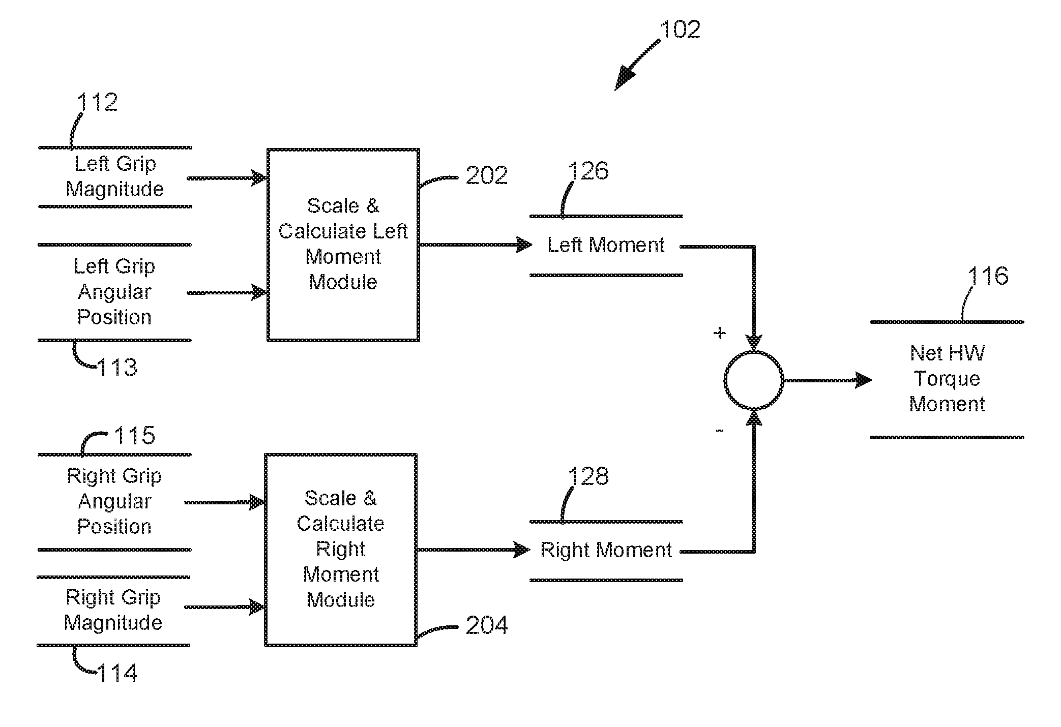
FIG. 3 depicts an example of the net handwheel torque moment determination module 102 in greater detail. In the example of FIG. 3, the net handwheel torque moment 116 is determined based on a left grip angular position 113 of the left grip 15A (FIG. 1) and a right grip angular position 115 of the right grip 15B (FIG. 1) of the handwheel 14 (FIG. 1) in reference to a straight ahead position. The left grip angular position 113 and the right grip angular position 115 can be determined based on readings from the grip sensors 35 (FIG. 1) and the handwheel position/velocity sensor 33 (FIG. 1). The net handwheel torque moment 116 is further determined based on a left moment 126 and a right moment 128 in response to a nominal measure of arm weight and geometry of the left grip angular position 113, the right grip angular position 115, and the handwheel 14. A scale and calculate left moment module 202 can produce the left moment 126 by scaling the left grip angular position 113 with respect to the left grip magnitude 112, for instance, as a product of the left grip magnitude 112 and an offset based on the left grip angular position 113. A scale and calculate right moment module 204 can produce the right moment 128 by scaling the right grip angular position 115 with respect to the right grip magnitude 114, for instance, as a product of the right grip magnitude 114 and an offset based on the right grip angular position 115. Left and right grip angular positions 113, 115 (as angles from vertical) and the radius of the handwheel 14 enable computation of the left moment 126 and right moment 128 respectively. The left grip magnitude 112 and right grip magnitude 114 can be applied for scaling depending on whether the grip is full or weak, which may indicate whether or not the full weight of an arm is transferred to the rim of the handwheel 14. The net handwheel torque moment 116 can be calculated as a difference between the left moment 126 and the right moment 128.
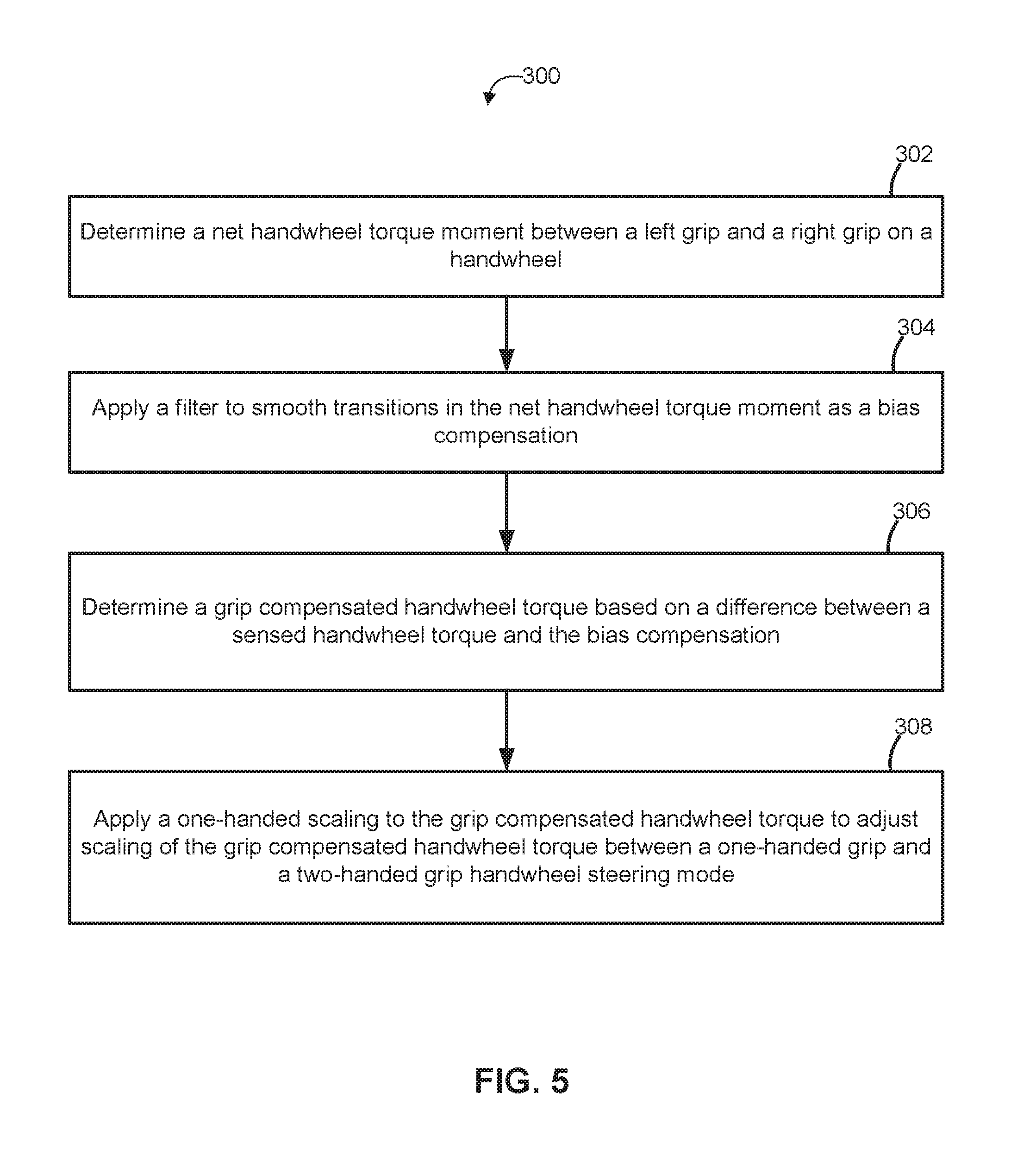
FIG. 5 illustrates a process 300 for grip-based handwheel compensation. Process 300 is described in further reference to FIGS. 1-4. At block 302, net handwheel torque moment module 102 of control module 40 determines a net handwheel torque moment 116 between a left grip 15A and a right grip 15B on a handwheel 14. At block 304, a filter is applied (e.g., by filter transition compensation module 104) to smooth transitions in the net handwheel torque moment 116 as a bias compensation 118. At block 306, a grip compensated handwheel torque 120 is determined (e.g., by handwheel torque compensation module 108) based on a difference between a sensed handwheel torque 110 and the bias compensation 118. At block 308, a one-handed scaling is applied (e.g., by handwheel torque compensation module 108) as gain compensation 122 (e.g., from scale one-handed module 106) to the grip compensated handwheel torque 120 to adjust scaling of the grip compensated handwheel torque 120 between a one-handed grip and a two-handed grip handwheel steering mode and produce the grip and one-handed compensated handwheel torque 124. The one-handed scaling can be a gain compensation 122 that is filtered to smooth transitions in the scaling of the grip compensated handwheel torque 120, for instance, when switching between one-handed and two-handed grips. The grip and one-handed compensated handwheel torque 124 can be used in place of the sensed handwheel torque 110 as a compensated value in control algorithms of the control module 40 used to command the steering actuator motor 19 of the steering system 12, thereby compensating for various grip patterns and one/two handed operation as opposed to an expected two-handed grip pattern at 10/2 or 9/3 o'clock on the handwheel 14.
While the invention has been described in detail in connection with only a limited number of embodiments, it should be readily understood that the invention is not limited to such disclosed embodiments. Rather, the invention can be modified to incorporate any number of variations, alterations, substitutions or equivalent arrangements not heretofore described, but which are commensurate with the spirit and scope of the invention. Additionally, while various embodiments of the invention have been described, it is to be understood that aspects of the invention may include only some of the described embodiments. Accordingly, the invention is not to be seen as limited by the foregoing description.
* * * * *
D00000
D00001
D00002
D00003
D00004
D00005
XML
uspto.report is an independent third-party trademark research tool that is not affiliated, endorsed, or sponsored by the United States Patent and Trademark Office (USPTO) or any other governmental organization. The information provided by uspto.report is based on publicly available data at the time of writing and is intended for informational purposes only.
While we strive to provide accurate and up-to-date information, we do not guarantee the accuracy, completeness, reliability, or suitability of the information displayed on this site. The use of this site is at your own risk. Any reliance you place on such information is therefore strictly at your own risk.
All official trademark data, including owner information, should be verified by visiting the official USPTO website at www.uspto.gov. This site is not intended to replace professional legal advice and should not be used as a substitute for consulting with a legal professional who is knowledgeable about trademark law.