Electric power steering mode determination and transitioning
Otto , et al.
U.S. patent number 10,363,958 [Application Number 15/656,075] was granted by the patent office on 2019-07-30 for electric power steering mode determination and transitioning. This patent grant is currently assigned to STEERING SOLUTIONS IP HOLDING CORPORATION. The grantee listed for this patent is STEERING SOLUTIONS IP HOLDING CORPORATION. Invention is credited to Jeffrey M. Otto, Rangarajan Ramanujam, Bhuvanesh Sainath.


View All Diagrams
| United States Patent | 10,363,958 |
| Otto , et al. | July 30, 2019 |
Electric power steering mode determination and transitioning
Abstract
Technical solutions are described for facilitating an electric power steering (EPS) system to determine an operating mode of a vehicle that is equipped with the EPS, where the operating mode is indicative of a level of autonomous driving being used by the vehicle. The technical solutions further facilitate detecting a change in the operating mode of the vehicle, and facilitating a transition in computing an assist signal for the EPS system during the transition between the operating modes.
| Inventors: | Otto; Jeffrey M. (Bay City, MI), Ramanujam; Rangarajan (Saginaw, MI), Sainath; Bhuvanesh (Saginaw, MI) | ||||||||||
|---|---|---|---|---|---|---|---|---|---|---|---|
| Applicant: |
|
||||||||||
| Assignee: | STEERING SOLUTIONS IP HOLDING
CORPORATION (Saginaw, MI) |
||||||||||
| Family ID: | 60951180 | ||||||||||
| Appl. No.: | 15/656,075 | ||||||||||
| Filed: | July 21, 2017 |
Prior Publication Data
| Document Identifier | Publication Date | |
|---|---|---|
| US 20180029640 A1 | Feb 1, 2018 | |
Related U.S. Patent Documents
| Application Number | Filing Date | Patent Number | Issue Date | ||
|---|---|---|---|---|---|
| 62366668 | Jul 26, 2016 | ||||
| Current U.S. Class: | 1/1 |
| Current CPC Class: | B62D 15/025 (20130101); B62D 5/0463 (20130101); B62D 6/007 (20130101); B62D 6/08 (20130101); G05D 1/021 (20130101); B62D 1/286 (20130101) |
| Current International Class: | B62D 15/02 (20060101); B62D 6/00 (20060101); G05D 1/02 (20060101); B62D 1/28 (20060101); B62D 6/08 (20060101); B62D 5/04 (20060101) |
References Cited [Referenced By]
U.S. Patent Documents
| 1795567 | March 1931 | Maurice |
| 3369425 | February 1968 | Runkle et al. |
| 3386309 | June 1968 | Reed et al. |
| 3396600 | August 1968 | Zeigler et al. |
| 3782492 | January 1974 | Hollins |
| 4138167 | February 1979 | Ernst et al. |
| 4315117 | February 1982 | Kokubo et al. |
| 4337967 | July 1982 | Yoshida et al. |
| 4476954 | October 1984 | Johnson et al. |
| 4503300 | March 1985 | Lane, Jr. |
| 4503504 | March 1985 | Suzumura et al. |
| 4509386 | April 1985 | Kimberlin |
| 4535645 | August 1985 | De Bisschop et al. |
| 4559816 | December 1985 | Ebert et al. |
| 4561323 | December 1985 | Stromberg |
| 4570776 | February 1986 | Iwashita et al. |
| 4598604 | July 1986 | Sorsche et al. |
| 4602520 | July 1986 | Nishikawa et al. |
| 4633732 | January 1987 | Nishikawa et al. |
| 4661752 | April 1987 | Nishikawa et al. |
| 4669325 | June 1987 | Nishikawa et al. |
| 4691587 | September 1987 | Farrand et al. |
| 4785684 | November 1988 | Nishikawa et al. |
| 4811580 | March 1989 | Jang |
| 4836566 | June 1989 | Birsching |
| 4881020 | November 1989 | Hida et al. |
| 4893518 | January 1990 | Matsumoto et al. |
| 4901544 | February 1990 | Jang |
| 4901593 | February 1990 | Ishikawa |
| 4921066 | May 1990 | Conley |
| 4941679 | July 1990 | Baumann et al. |
| 4943028 | July 1990 | Hoffmann et al. |
| 4962570 | October 1990 | Hosaka et al. |
| 4967618 | November 1990 | Matsumoto et al. |
| 4976239 | December 1990 | Hosaka |
| 5048364 | September 1991 | Minamoto et al. |
| 5226853 | July 1993 | Courgeon |
| 5240284 | August 1993 | Takada et al. |
| 5295712 | March 1994 | Omura |
| 5311432 | May 1994 | Momose |
| 5319803 | June 1994 | Allen |
| 5428873 | July 1995 | Hitchcock et al. |
| 5488555 | January 1996 | Asgari |
| 5590565 | January 1997 | Palfenier et al. |
| 5606892 | March 1997 | Hedderly |
| 5613404 | March 1997 | Lykken et al. |
| 5618058 | April 1997 | Byon |
| 5668721 | September 1997 | Chandy |
| 5678454 | October 1997 | Cartwright et al. |
| 5690362 | November 1997 | Peitsmeier et al. |
| 5737971 | April 1998 | Riefe et al. |
| 5765116 | June 1998 | Wilson-Jones et al. |
| 5813699 | September 1998 | Donner et al. |
| 5890397 | April 1999 | Stoner et al. |
| 5893580 | April 1999 | Hoagland et al. |
| 5911789 | June 1999 | Keipert et al. |
| 5931250 | August 1999 | Kagawa et al. |
| 5941130 | August 1999 | Olgren et al. |
| 6041677 | March 2000 | Reh et al. |
| 6070686 | June 2000 | Pollmann |
| 6079513 | June 2000 | Nishizaki et al. |
| 6142523 | November 2000 | Bathis et al. |
| 6170862 | January 2001 | Hoagland et al. |
| 6220630 | April 2001 | Sundholm et al. |
| 6227571 | May 2001 | Sheng et al. |
| 6234040 | May 2001 | Weber et al. |
| 6264239 | July 2001 | Link |
| 6301534 | October 2001 | McDermott, Jr. |
| 6343993 | February 2002 | Duval et al. |
| 6354622 | March 2002 | Ulbrich et al. |
| 6354626 | March 2002 | Cartwright |
| 6360149 | March 2002 | Kwon et al. |
| 6373472 | April 2002 | Palalau et al. |
| 6381526 | April 2002 | Higashi et al. |
| 6390505 | May 2002 | Wilson |
| 6460427 | October 2002 | Hedderly |
| 6571587 | June 2003 | Dimig et al. |
| 6578449 | June 2003 | Anspaugh et al. |
| 6611745 | August 2003 | Paul |
| 6612198 | September 2003 | Rouleau et al. |
| 6612393 | September 2003 | Bohner et al. |
| 6819990 | November 2004 | Ichinose |
| 7021416 | April 2006 | Kapaan et al. |
| 7025380 | April 2006 | Arihara |
| 7048305 | May 2006 | Muller |
| 7062365 | June 2006 | Fei |
| 7140213 | November 2006 | Feucht et al. |
| 7159904 | January 2007 | Schafer et al. |
| 7213842 | May 2007 | Uehle et al. |
| 7258365 | August 2007 | Kahlenberg et al. |
| 7261014 | August 2007 | Arihara |
| 7290800 | November 2007 | Schwarzbich et al. |
| 7295904 | November 2007 | Kanevsky et al. |
| 7308964 | December 2007 | Hara et al. |
| 7410190 | August 2008 | Sawada et al. |
| 7428944 | September 2008 | Gerum |
| 7461863 | December 2008 | Muller |
| 7495584 | February 2009 | Sorensen |
| 7533594 | May 2009 | Menjak et al. |
| 7628244 | December 2009 | Chino et al. |
| 7719431 | May 2010 | Bolourchi |
| 7735405 | June 2010 | Parks |
| 7758073 | July 2010 | Chou |
| 7775129 | August 2010 | Oike et al. |
| 7784830 | August 2010 | Ulintz |
| 7793980 | September 2010 | Fong |
| 7862079 | January 2011 | Fukawatase et al. |
| 7975569 | January 2011 | Klos |
| 7894951 | February 2011 | Norris et al. |
| 7909361 | March 2011 | Oblizajek et al. |
| 7913803 | March 2011 | Hidaka |
| 8002075 | August 2011 | Markfort |
| 8011265 | September 2011 | Menjak et al. |
| 8021235 | September 2011 | Tinnin et al. |
| 8027767 | September 2011 | Klein et al. |
| 8055409 | November 2011 | Tsuchiya |
| 8069745 | December 2011 | Strieter et al. |
| 8079312 | December 2011 | Long |
| 8146945 | April 2012 | Born et al. |
| 8161839 | April 2012 | Warashina |
| 8170725 | May 2012 | Chin et al. |
| 8260482 | September 2012 | Szybalski et al. |
| 8352110 | January 2013 | Szybalski et al. |
| 8466382 | June 2013 | Donicke |
| 8479605 | July 2013 | Shavrnoch et al. |
| 8548667 | October 2013 | Kaufmann |
| 8606455 | December 2013 | Boehringer et al. |
| 8634980 | January 2014 | Urmson et al. |
| 8650982 | February 2014 | Matsuno et al. |
| 8670891 | March 2014 | Szybalski et al. |
| 8695750 | April 2014 | Hammond et al. |
| 8733201 | May 2014 | Okano et al. |
| 8818608 | August 2014 | Cullinane et al. |
| 8825258 | September 2014 | Cullinane et al. |
| 8825261 | September 2014 | Szybalski et al. |
| 8843268 | September 2014 | Lathrop et al. |
| 8874301 | October 2014 | Rao et al. |
| 8880287 | November 2014 | Lee et al. |
| 8881861 | November 2014 | Tojo |
| 8899623 | December 2014 | Stadler et al. |
| 8909428 | December 2014 | Lombrozo |
| 8948993 | February 2015 | Schulman et al. |
| 8950543 | February 2015 | Heo et al. |
| 8955407 | February 2015 | Sakuma |
| 8994521 | March 2015 | Gazit |
| 9002563 | April 2015 | Green et al. |
| 9031729 | May 2015 | Lathrop et al. |
| 9032835 | May 2015 | Davies et al. |
| 9039041 | May 2015 | Buzzard et al. |
| 9045078 | June 2015 | Tovar et al. |
| 9073574 | July 2015 | Cuddihy et al. |
| 9080895 | July 2015 | Martin et al. |
| 9092093 | July 2015 | Jubner et al. |
| 9108584 | August 2015 | Rao et al. |
| 9134729 | September 2015 | Szybalski et al. |
| 9150200 | October 2015 | Urhahne |
| 9150224 | October 2015 | Yopp |
| 9164619 | October 2015 | Goodlein |
| 9174642 | November 2015 | Wimmer et al. |
| 9186994 | November 2015 | Okuyama et al. |
| 9193375 | November 2015 | Schramm et al. |
| 9199553 | December 2015 | Cuddihy et al. |
| 9227531 | January 2016 | Cuddihy et al. |
| 9233638 | January 2016 | Lisseman et al. |
| 9235111 | January 2016 | Yamaguchi |
| 9235211 | January 2016 | Davidsson et al. |
| 9235987 | January 2016 | Green et al. |
| 9238409 | January 2016 | Lathrop et al. |
| 9248743 | February 2016 | Enthaler et al. |
| 9260130 | February 2016 | Mizuno |
| 9290174 | March 2016 | Zagorski |
| 9290201 | March 2016 | Lombrozo |
| 9296410 | March 2016 | Isogai et al. |
| 9298184 | March 2016 | Bartels et al. |
| 9308857 | April 2016 | Lisseman et al. |
| 9308891 | April 2016 | Cudak et al. |
| 9333983 | May 2016 | Lathrop et al. |
| 9352752 | May 2016 | Cullinane et al. |
| 9360108 | June 2016 | Pfenninger et al. |
| 9360865 | June 2016 | Yopp |
| 9421994 | August 2016 | Agbor et al. |
| 9487228 | November 2016 | Febre et al. |
| 9550514 | January 2017 | Schulz et al. |
| 9616914 | April 2017 | Stinebring et al. |
| 9643641 | May 2017 | Stinebring et al. |
| 9663136 | May 2017 | Stinebring et al. |
| 9744983 | August 2017 | Stinebring et al. |
| 9828016 | November 2017 | Lubischer |
| 9845106 | December 2017 | Bodtker |
| 9849904 | December 2017 | Rouleau |
| 9862403 | January 2018 | Rouleau et al. |
| 9919724 | March 2018 | Lubischer et al. |
| 10065655 | September 2018 | Bendewald et al. |
| 10131375 | November 2018 | Schmidt et al. |
| 2002/0171235 | November 2002 | Riefe et al. |
| 2003/0046012 | March 2003 | Yamaguchi |
| 2003/0094330 | May 2003 | Boloorchi et al. |
| 2003/0146037 | August 2003 | Menjak et al. |
| 2003/0183440 | October 2003 | Thomas et al. |
| 2003/0188598 | October 2003 | Cartwright |
| 2003/0227159 | December 2003 | Muller |
| 2004/0016588 | January 2004 | Vitale et al. |
| 2004/0046346 | March 2004 | Eki et al. |
| 2004/0046379 | March 2004 | Riefe |
| 2004/0099083 | May 2004 | Choi et al. |
| 2004/0099468 | May 2004 | Chernoff et al. |
| 2004/0129098 | July 2004 | Gayer et al. |
| 2004/0204808 | October 2004 | Satoh et al. |
| 2004/0262063 | December 2004 | Kaufmann et al. |
| 2005/0001445 | January 2005 | Ercolano |
| 2005/0081675 | April 2005 | Oshita et al. |
| 2005/0197746 | September 2005 | Pelchen et al. |
| 2005/0242562 | November 2005 | Ridgway et al. |
| 2005/0263996 | December 2005 | Manwaring et al. |
| 2005/0275205 | December 2005 | Ahnafield |
| 2006/0005658 | January 2006 | Armstrong et al. |
| 2006/0186658 | August 2006 | Yasuhara et al. |
| 2006/0202463 | September 2006 | Schwarzbich et al. |
| 2006/0219499 | October 2006 | Organek |
| 2006/0224287 | October 2006 | Izawa et al. |
| 2006/0237959 | October 2006 | Dimig et al. |
| 2006/0244251 | November 2006 | Muller |
| 2006/0283281 | December 2006 | Li et al. |
| 2007/0021889 | January 2007 | Tsuchiya |
| 2007/0029771 | February 2007 | Haglund et al. |
| 2007/0046003 | March 2007 | Mori et al. |
| 2007/0046013 | March 2007 | Bito et al. |
| 2007/0096446 | May 2007 | Breed |
| 2007/0126222 | June 2007 | Koya et al. |
| 2007/0158116 | July 2007 | Peppler |
| 2007/0241548 | October 2007 | Fong |
| 2007/0284867 | December 2007 | Cymbal et al. |
| 2008/0009986 | January 2008 | Lu et al. |
| 2008/0028884 | February 2008 | Monash |
| 2008/0047382 | February 2008 | Tomaru et al. |
| 2008/0079253 | April 2008 | Sekii et al. |
| 2008/0147276 | June 2008 | Pattok et al. |
| 2008/0216597 | September 2008 | Iwakawa et al. |
| 2008/0238068 | October 2008 | Kumar et al. |
| 2008/0264196 | October 2008 | Schindler et al. |
| 2009/0024278 | January 2009 | Kondo et al. |
| 2009/0056493 | March 2009 | Dubay et al. |
| 2009/0107284 | April 2009 | Lucas et al. |
| 2009/0229400 | September 2009 | Ozsoylu et al. |
| 2009/0256342 | October 2009 | Cymbal et al. |
| 2009/0266195 | October 2009 | Tanke et al. |
| 2009/0276111 | November 2009 | Wang et al. |
| 2009/0280914 | November 2009 | Kakutani et al. |
| 2009/0292466 | November 2009 | McCarthy et al. |
| 2010/0152952 | June 2010 | Lee et al. |
| 2010/0218637 | September 2010 | Barroso |
| 2010/0222976 | September 2010 | Haug |
| 2010/0228417 | September 2010 | Lee et al. |
| 2010/0228438 | September 2010 | Buerkle |
| 2010/0280713 | November 2010 | Stahlin et al. |
| 2010/0286869 | November 2010 | Katch et al. |
| 2010/0288567 | November 2010 | Bonne |
| 2011/0098922 | April 2011 | Ibrahim |
| 2011/0153160 | June 2011 | Hesseling et al. |
| 2011/0167940 | July 2011 | Shavrnoch et al. |
| 2011/0187518 | August 2011 | Strumolo et al. |
| 2011/0266396 | November 2011 | Abildgaard et al. |
| 2011/0282550 | November 2011 | Tada et al. |
| 2011/0314954 | December 2011 | Matsuno et al. |
| 2012/0136540 | May 2012 | Miller |
| 2012/0205183 | August 2012 | Rombold |
| 2012/0209473 | August 2012 | Birsching et al. |
| 2012/0215377 | August 2012 | Takemura et al. |
| 2012/0247259 | October 2012 | Mizuno et al. |
| 2012/0287050 | November 2012 | Wu |
| 2013/0002416 | January 2013 | Gazit |
| 2013/0325202 | January 2013 | Howard et al. |
| 2013/0087006 | April 2013 | Ohtsubo et al. |
| 2013/0104689 | May 2013 | Marutani et al. |
| 2013/0133463 | May 2013 | Moriyama |
| 2013/0158771 | June 2013 | Kaufmann |
| 2013/0174686 | July 2013 | Hirche et al. |
| 2013/0199866 | August 2013 | Yamamoto et al. |
| 2013/0205933 | August 2013 | Moriyama |
| 2013/0218396 | August 2013 | Moshchuk et al. |
| 2013/0233117 | September 2013 | Read et al. |
| 2013/0292955 | November 2013 | Higgins et al. |
| 2013/0325264 | December 2013 | Alcazar et al. |
| 2014/0028008 | January 2014 | Stadler et al. |
| 2014/0046542 | February 2014 | Kauffman et al. |
| 2014/0046547 | February 2014 | Kauffman et al. |
| 2014/0111324 | April 2014 | Lisseman et al. |
| 2014/0300479 | April 2014 | Wolter et al. |
| 2014/0116187 | May 2014 | Tinnin |
| 2014/0137694 | May 2014 | Sugiura |
| 2014/0277896 | September 2014 | Lathrop et al. |
| 2014/0309816 | October 2014 | Stefan et al. |
| 2015/0002404 | January 2015 | Hooton |
| 2015/0014086 | January 2015 | Eisenbarth |
| 2015/0032322 | January 2015 | Wimmer et al. |
| 2015/0051780 | January 2015 | Hahne |
| 2015/0120142 | January 2015 | Park et al. |
| 2015/0060185 | March 2015 | Feguri |
| 2015/0246673 | April 2015 | Tseng et al. |
| 2015/0137492 | May 2015 | Rao et al. |
| 2015/0203145 | July 2015 | Sugiura et al. |
| 2015/0203149 | July 2015 | Katayama |
| 2015/0210273 | July 2015 | Kaufmann et al. |
| 2015/0251666 | July 2015 | Attard et al. |
| 2015/0283998 | September 2015 | Lind et al. |
| 2015/0324111 | September 2015 | Jubner et al. |
| 2015/0375769 | December 2015 | Abboud et al. |
| 2016/0009332 | January 2016 | Sirbu |
| 2016/0016604 | January 2016 | Johta et al. |
| 2016/0075371 | March 2016 | Varunkikar et al. |
| 2016/0082867 | March 2016 | Sugioka et al. |
| 2016/0200246 | March 2016 | Lisseman et al. |
| 2016/0114828 | April 2016 | Tanaka et al. |
| 2016/0185387 | June 2016 | Kuoch |
| 2016/0200343 | June 2016 | Lisseman et al. |
| 2016/0200344 | July 2016 | Sugioka et al. |
| 2016/0207538 | July 2016 | Urano et al. |
| 2016/0209841 | July 2016 | Yamaoka et al. |
| 2016/0229450 | July 2016 | Basting et al. |
| 2016/0231743 | July 2016 | Bendewald et al. |
| 2016/0244070 | August 2016 | Bendewald et al. |
| 2016/0244086 | August 2016 | Moriyama |
| 2016/0252133 | September 2016 | Caverly |
| 2016/0318540 | November 2016 | King |
| 2016/0318542 | November 2016 | Pattok et al. |
| 2016/0347347 | December 2016 | Lubischer et al. |
| 2016/0347348 | December 2016 | Lubischer et al. |
| 2016/0362084 | December 2016 | Martin et al. |
| 2016/0362117 | December 2016 | Kaufmann et al. |
| 2016/0362126 | December 2016 | Lubischer |
| 2016/0368522 | December 2016 | Lubischer |
| 2016/0375770 | December 2016 | Ryne et al. |
| 2016/0375860 | December 2016 | Lubischer |
| 2016/0375923 | December 2016 | Schulz |
| 2016/0375924 | December 2016 | Bodtker et al. |
| 2016/0375925 | December 2016 | Lubischer et al. |
| 2016/0375926 | December 2016 | Lubischer et al. |
| 2016/0375927 | December 2016 | Schulz et al. |
| 2016/0375928 | December 2016 | Magnus |
| 2016/0375929 | December 2016 | Rouleau |
| 2016/0375931 | December 2016 | Lubischer et al. |
| 2017/0029009 | February 2017 | Rouleau |
| 2017/0029018 | February 2017 | Lubischer et al. |
| 2017/0097071 | April 2017 | Galehr |
| 2017/0106894 | April 2017 | Bodtker |
| 2017/0106895 | April 2017 | Jager et al. |
| 2017/0113589 | April 2017 | Riefe |
| 2017/0113712 | April 2017 | Watz |
| 2017/0151975 | July 2017 | Schmidt et al. |
| 2017/0294120 | October 2017 | Ootsuji |
| 2017/0297606 | October 2017 | Kim et al. |
| 2017/0361863 | December 2017 | Rouleau |
| 2017/0369091 | December 2017 | Nash |
| 2018/0029628 | February 2018 | Sugishita |
| 2018/0050720 | February 2018 | King et al. |
| 2018/0079441 | March 2018 | McKinzie et al. |
| 2018/0086378 | March 2018 | Bell et al. |
| 2018/0111639 | April 2018 | Bodtker et al. |
| 2018/0148084 | May 2018 | Nash et al. |
| 2018/0154932 | June 2018 | Rakouth et al. |
| 2018/0229753 | August 2018 | Magnus et al. |
| 2018/0238400 | August 2018 | Magnus et al. |
| 2018/0251147 | September 2018 | Heitz et al. |
| 2018/0273081 | September 2018 | Lubischer et al. |
| 1449952 | Oct 2003 | CN | |||
| 1550395 | Dec 2004 | CN | |||
| 1722030 | Jan 2006 | CN | |||
| 1736786 | Feb 2006 | CN | |||
| 101037117 | Sep 2007 | CN | |||
| 101041355 | Sep 2007 | CN | |||
| 101049814 | Oct 2007 | CN | |||
| 101291840 | Oct 2008 | CN | |||
| 101402320 | Apr 2009 | CN | |||
| 101596903 | Dec 2009 | CN | |||
| 201534560 | Jul 2010 | CN | |||
| 101954862 | Jan 2011 | CN | |||
| 102161346 | Aug 2011 | CN | |||
| 102452391 | May 2012 | CN | |||
| 102523738 | Jun 2012 | CN | |||
| 102574545 | Jul 2012 | CN | |||
| 202337282 | Jul 2012 | CN | |||
| 102806937 | Dec 2012 | CN | |||
| 103085854 | May 2013 | CN | |||
| 103419840 | Dec 2013 | CN | |||
| 103448785 | Dec 2013 | CN | |||
| 103569185 | Feb 2014 | CN | |||
| 103587571 | Feb 2014 | CN | |||
| 203793405 | Aug 2014 | CN | |||
| 204222957 | Mar 2015 | CN | |||
| 4310431 | Oct 1994 | DE | |||
| 19523214 | Jan 1997 | DE | |||
| 19923012 | Nov 2000 | DE | |||
| 19954505 | May 2001 | DE | |||
| 10212782 | Oct 2003 | DE | |||
| 102005032528 | Jan 2007 | DE | |||
| 102005056438 | Jun 2007 | DE | |||
| 102006025254 | Dec 2007 | DE | |||
| 1020081057313 | Oct 2009 | DE | |||
| 102010025197 | Dec 2011 | DE | |||
| 102013110865 | Apr 2015 | DE | |||
| 102015216326 | Sep 2016 | DE | |||
| 1559630 | Aug 2005 | EP | |||
| 1783719 | May 2007 | EP | |||
| 1932745 | Jun 2008 | EP | |||
| 2384946 | Nov 2011 | EP | |||
| 2426030 | Mar 2012 | EP | |||
| 2489577 | Aug 2012 | EP | |||
| 2604487 | Jun 2013 | EP | |||
| 1606149 | May 2014 | EP | |||
| 2862595 | May 2005 | FR | |||
| 3016327 | Jul 2015 | FR | |||
| S58191668 | Nov 1983 | JP | |||
| 60164629 | Aug 1985 | JP | |||
| S60157963 | Aug 1985 | JP | |||
| H05162652 | Jun 1993 | JP | |||
| 2007253809 | Oct 2007 | JP | |||
| 2012201334 | Oct 2012 | JP | |||
| 20100063433 | Jun 2010 | KR | |||
| 101062339 | Sep 2011 | KR | |||
| 2006099483 | Sep 2006 | WO | |||
| 2010082394 | Jul 2010 | WO | |||
| 2010116518 | Oct 2010 | WO | |||
| 2014208573 | Dec 2014 | WO | |||
Other References
|
China Patent Application No. 201510204221.5 Second Office Action dated Mar. 10, 2017, 8 pages. cited by applicant . CN OA dated Oct. 27, 2017. cited by applicant . CN Patent Application No. 201210599006.6 First Office Action dated Jan. 27, 2015, 9 pages. cited by applicant . CN Patent Application No. 201210599006.6 Second Office Action dated Aug. 5, 2015, 5 pages. cited by applicant . CN Patent Application No. 201310178012.9 First Office Action dated Apr. 13, 2015, 13 pages. cited by applicant . CN Patent Application No. 201310178012.9 Second Office Action dated Dec. 28, 2015, 11 pages. cited by applicant . CN Patent Application No. 201410089167 First Office Action and Search Report dated Feb. 3, 2016, 9 pages. cited by applicant . EP Application No. 14156903.8 Extended European Search Report, dated Jan. 27, 2015, 10 pages. cited by applicant . EP Application No. 14156903.8 Office Action dated Nov. 16, 2015, 4 pages. cited by applicant . EP Application No. 14156903.8 Office Action dated May 31, 2016, 5 pages. cited by applicant . EP Application No. 14156903.8 Partial European Search Report dated Sep. 23, 2014, 6 pages. cited by applicant . EP Application No. 15152834.6 Extended European Search Report dated Oct. 8, 2015, 7 pages. cited by applicant . European Application No. 12196665.9 Extended European Search Report dated Mar. 6, 2013, 7 pages. cited by applicant . European Search Report for European Application No. 13159950.8; dated Jun. 6, 2013; 7 pages. cited by applicant . European Search Report for related European Application No. 15152834.6, dated: Oct. 8, 2015; 7 pages. cited by applicant . Gillespie, Thomas D.; "Fundamentals of Vehicle Dynamics"; Society of Automotive Enginers, Inc.; published 1992; 294 pages. cited by applicant . Kichun, et al.; "Development of Autonomous Car--Part II: A Case Study on the Implementation of an Autonomous Driving System Based on Distributed Architecture"; IEEE Transactions on Industrial Electronics, vol. 62, No. 8, Aug. 2015; 14 pages. cited by applicant . Partial European Search Report for related European Patent Application No. 14156903.8, dated Sep. 23, 2014, 6 pages. cited by applicant . Van der Jagt, Pim; "Prediction of Steering Efforts During Stationary or Slow Rolling Parking Maneuvers"; Ford Forschungszentrum Aachen GmbH.; Oct. 27, 1999; 20 pages. cited by applicant . Van Der Jagt, Pim; "Prediction of steering efforts during stationary or slow rolling parking maneuvers"; Jul. 2013, 20 pages. cited by applicant . Varunjikar, Tejas; Design of Horizontal Curves With DownGrades Using Low-Order Vehicle Dynamics Models; A Theisis by T. Varunkikar; 2011; 141 pages. cited by applicant . English translation regarding DE102015216326B4, ThyssenKrupp AG; 21 pgs. cited by applicant . Chinese Office Action & Search Report for Chinese Application No. 2016103666609.X dated Dec. 20, 2017, including English Translation, 16 pages. cited by applicant . Chinese Office Action & Search Report for Chinese Application No. 201610427896.0 dated Oct. 27, 2017, 16 pages, English Translation Included. cited by applicant . Chinese Office Action & Search Report for Chinese Application No. 201610609647.3 dated Mar. 12, 2018, 5 pages, no English translation available. cited by applicant . Chinese Office Action & Search Report for Chinese Application No. 201610620335.2 dated Jan. 22, 2018, 15 pages, English Translation Included. cited by applicant . Chinese Office Action & Search Report for Chinese Application No. 201610642300.9 dated Feb. 7, 2018, 22 pages, English Translation Only. cited by applicant . Chinese Office Action & Search Report for Chinese Application No. 201610651953.3 dated Jan. 25, 2018, 12 pages, English Translation Included. cited by applicant . Chinese Office Action & Search Report for Chinese Application No. 201610830808.1 dated Apr. 3, 2018, 30 pages, English Translation Included. cited by applicant . Chinese Office Action & Search Report for Chinese Application No. 201610830809.6 dated Mar. 12, 2018, 11 pages, English Translation Included. cited by applicant . Chinese Office Action & Search Report for Chinese Application No. 201610830810.9 dated Jan. 31, 2018, 18 pages, English Translation Included. cited by applicant . Chinese Office Action & Search Report for Chinese Application No. 201611113746.9 dated May 4, 2018, 11 pages, English Translation Included. cited by applicant . Chinese Office Action for Chinese Application No. 201610427896.0 dated May 28, 2018 16 pages, English Translation Included. cited by applicant . CN Chinese Office Action & Search Report for Chinese Application No. 201610620335.2 dated Aug. 7, 2018, 16 pages, English Translation Included. cited by applicant. |
Primary Examiner: Lee; Tyler J
Parent Case Text
CROSS-REFERENCES TO RELATED APPLICATIONS
This patent application claims priority to U.S. Provisional Patent Application Ser. No. 62/366,668, filed Jul. 26, 2016, which is incorporated herein by reference in its entirety.
Claims
What is claimed is:
1. An electric power steering system comprising: an advance driver assist module configured to: determine an operation mode that indicates a level of autonomous driving, the operation mode being a first operation mode from a plurality of levels of autonomous driving comprising at least a fully automated operation mode, a semi-automated operation mode, and a non-automated operation mode; detect a change from the first operation mode to a second operation mode; and transition performance of the electric power steering system from the first operation mode to the second operation mode, the transitioning comprising: determining a blend factor for adjusting the performance of the electric power steering system that is operating using a first calibration factor of the first operation mode to a second calibration factor of the second operation mode, the blend factor based on a vehicle speed; scaling the second calibration factor using the blend factor; and generating a steering system command using the scaled second calibration factor.
2. The electric power steering system of claim 1, wherein determining the operation mode is based on an amount of intervening handwheel torque measured during operation.
3. The electric power steering system of claim 1, wherein detecting the change from the first operation mode to the second operation mode is based on a change in a vehicle configuration, and an amount of intervening handwheel torque, at a vehicle speed that is below a predetermined speed threshold.
4. The electric power steering system of claim 1, further comprising a control module configured to generate the steering system command, which comprises a motor torque command using the scaled second calibration factor.
5. The electric power steering system of claim 1, wherein transitioning the performance comprises: switching off an EPS function.
6. The electric power steering system of claim 1, wherein the first operation mode is one of a human operator mode or a hybrid mode and the second operation mode is an autonomous mode.
7. The electric power steering system of claim 1, wherein the first operation mode is a human operator mode and the second operation mode is a hybrid mode.
8. The electric power steering system of claim 1, wherein the first operation mode is a hybrid mode and the second operation mode is a human operator mode.
9. The electric power steering system of claim 1, wherein transitioning the performance comprises: setting a value of a transition-complete flag based on the blend factor, the transition-complete flag being set to TRUE based on the blend factor exceeding a maximum threshold, and set to FALSE otherwise.
10. An advance driver assist module for an electric power steering system, which is configured to: determine an operation mode that indicates a level of autonomous driving, the operation mode being a first operation mode from a plurality of levels of autonomous driving comprising at least a fully automated operation mode, a semi-automated operation mode, and a non-automated operation mode; detect a change from the first operation mode to a second operation mode; and transition performance of the electric power steering system from the first operation mode to the second operation mode, the transitioning comprising: determining a blend factor for adjusting the performance of the electric power steering system that is operating using a first calibration factor of the first operation mode to a second calibration factor of the second operation mode, the blend factor based on a vehicle speed; scaling the second calibration factor using the blend factor; and generating a steering system command using the scaled second calibration factor.
11. The advance driver assist module of claim 10, wherein determining the operation mode is based on an amount of handwheel torque.
12. The advance driver assist module of claim 10, wherein detecting the change from the first operation mode to the second operation mode is based on a change in a vehicle configuration, and an amount of handwheel torque, at a vehicle speed that is below a predetermined speed threshold.
13. The advance driver assist module of claim 10, wherein detecting the change from the first operation mode to the second operation mode is based on a request to switch to the second operation mode.
14. The advance driver assist module of claim 10, further comprising a control module configured to generate the steering system command, which comprises a motor torque command using the scaled second calibration factor.
15. A method for providing assist signal to an electric power steering system, the method comprising: determining an operation mode of the electric power steering system, the operation mode indicates a level of autonomous driving of a vehicle equipped with the electric power steering system, the operation mode being a first operation mode from a plurality of levels of autonomous driving comprising at least a fully automated operation mode, a semi-automated operation mode, and a non-automated operation mode; detecting a change from the first operation mode to a second operation mode; and transitioning performance of the electric power steering system from the first operation mode to the second operation mode, the transitioning comprising: determining a blend factor for adjusting the performance of the electric power steering system that is operating using a first calibration factor of the first operation mode to a second calibration factor of the second operation mode, the blend factor based on a vehicle speed; scaling the second calibration factor using the blend factor; and generating a steering system command using the scaled second calibration factor.
16. The method of claim 15, wherein determining the operation mode is based on an amount of handwheel torque.
17. The method of claim 15, wherein detecting the change from the first operation mode to the second operation mode is based on a change in a vehicle configuration, and an amount of handwheel torque, at a vehicle speed that is below a predetermined speed threshold.
18. The method of claim 15, further comprising: in response to receiving a sensor failure indication, bypassing a fault response associated with the sensor failure in response to the electric power steering system being operated in the first operation mode, which is an autonomous mode.
Description
BACKGROUND
The present application generally relates to electric power steering (EPS) systems, and particularly to EPS with advanced driver assist systems (ADAS).
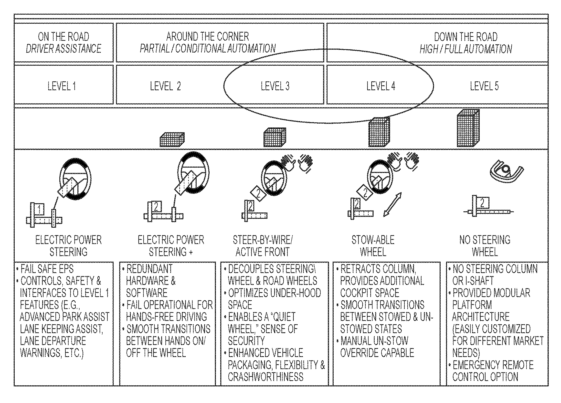
The Society of Automotive Engineers (SAE) in SAE Standard J3016 has defined six levels of driving automation: 0 (no automation), 1 (driver assistance), 2 (partial automation), 3 (conditional automation), 4 (high automation), and 5 (full automation). For example, FIG. 1 depicts some of the example levels determined in the SAE J3016 standards. SAE Level 3 autonomy requires that execution of and monitoring of (the) driving environment be handled by a system while the fallback performance of dynamic driving tasks be the responsibility of a human driver. As ADAS transform the auto-industry, EPS systems are adapting to accommodate that market segment. For example, EPS systems are desired that support use cases that are SAE Level 3 compatible in the short-term, which eventually operate in Level 4, the levels being those determined by the SAE J3016 standards related to on-road motor vehicle automated driving systems.
Accordingly, it is desirable to develop EPS systems that are compatible with the proposed standards. For example, it is desirable that the EPS system determine a mode of operation between a highly automated operating mode and a fully automated operating mode. Further, it is desirable that the EPS system hardware be controllable to handle inertial effects of steering wheel that is no longer in use in the fully automated operating mode. Further yet, it is desirable that EPS systems monitor and record diagnostics appropriately, for example torque sensor faults, which are unique per mode of operation.
SUMMARY
One or more embodiments are described for an electric power steering system that includes an advance driver assist module. The advance driver assist module determines an operation mode that indicates a level of autonomous driving, the operation mode being a first operation mode. The advance driver assist module further detects a change from the first operation mode to a second operation mode. Further, the advance driver assist module transitions performance of the electric power steering system from the first operation mode to the second operation mode.
Further, one or more embodiments are also described of an advance driver assist module for an electric power steering system. The advance driver assist module determines an operation mode that indicates a level of autonomous driving, the operation mode being a first operation mode. The advance driver assist module detects a change from the first operation mode to a second operation mode. Further, the advance driver assist module transitions performance of the electric power steering system from the first operation mode to the second operation mode.
Further, one or more embodiments of a method for providing assist signal to an electric power steering system are described. The method includes determining an operation mode of the electric power steering system, the operation mode indicates a level of autonomous driving of a vehicle equipped with the electric power steering system, wherein the operation mode is a first operation mode. The method further includes detecting a change from the first operation mode to a second operation mode. The method further includes transitioning performance of the electric power steering system from the first operation mode to the second operation mode.
These and other advantages and features will become more apparent from the following description taken in conjunction with the drawings.
BRIEF DESCRIPTION OF THE DRAWINGS
The subject matter which is regarded as the invention is particularly pointed out and distinctly claimed in the claims at the conclusion of the specification. The foregoing and other features, and advantages of the invention are apparent from the following detailed description taken in conjunction with the accompanying drawings in which:
FIG. 1 depicts example levels determined in the SAE J3016 standards.
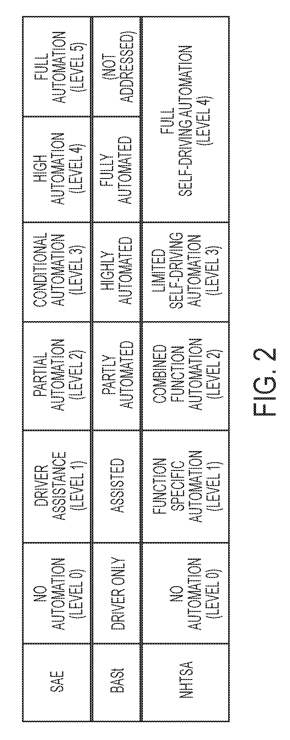
FIG. 2 illustrates a comparison between the levels in different standards.
FIG. 3 illustrates an exemplary embodiment of a vehicle including a steering system.
FIG. 4 illustrates an overview of a rack-based electric power steering (EPS) system and a column-based EPS system according to one or more embodiments.
FIG. 5 illustrates a block diagram for determining steering mode and transitioning between the steering modes according to one or more embodiments.
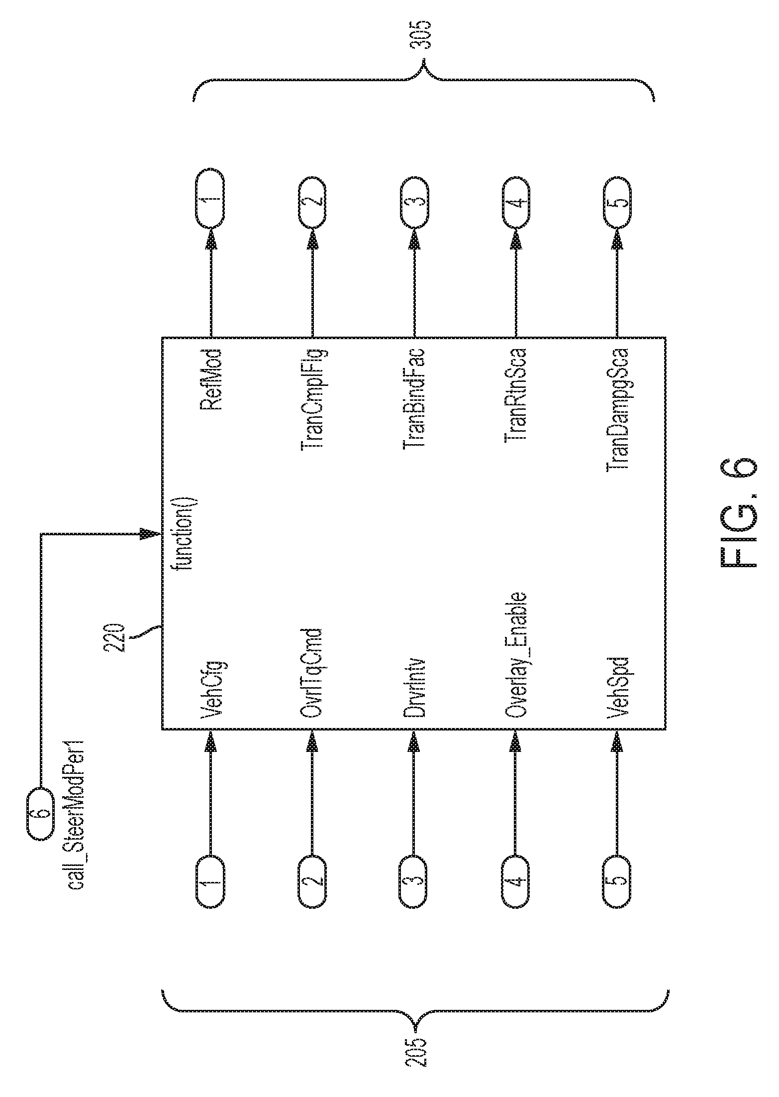
FIG. 6 depicts a block diagram for an example implementation of the advance driver assist module according to one or more embodiments.
FIG. 7 depicts a block diagram of example components of the advance driver assist module according to one or more embodiments.
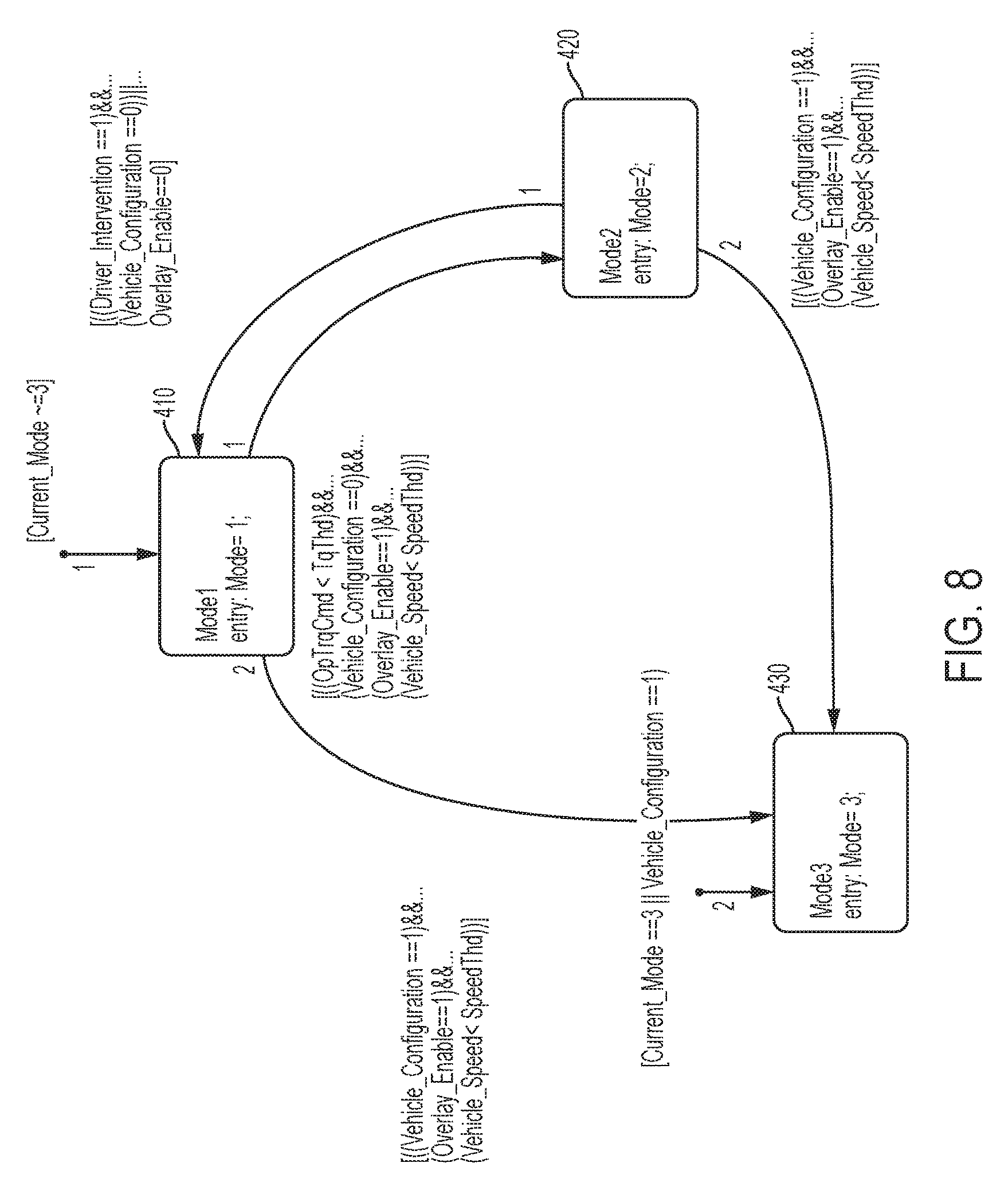
FIG. 8 depicts an example logic used by the mode determination module according to one or more embodiments.
FIG. 9 depicts an example dataflow for the transition module according to one or more embodiments.
FIG. 10 depicts a flowchart for an example method for determining and transitioning an EPS system from one operating mode to another according to one or more embodiments.
FIG. 11 depicts a flowchart for an example method for fault response according to one or more embodiments.
DETAILED DESCRIPTION
As used herein the terms module and sub-module refer to one or more processing circuits such as an application specific integrated circuit (ASIC), an electronic circuit, a processor (shared, dedicated, or group) and memory that executes one or more software or firmware programs, a combinational logic circuit, and/or other suitable components that provide the described functionality. As can be appreciated, the sub-modules described below can be combined and/or further partitioned.
The technical solutions herein facilitate an EPS system that is compatible with multiple levels of proposed standards for ADAS, particularly compatible with Level 3 and further of the SAE J3016 standards. For example, the technical solutions facilitate the EPS system to determine a mode of operation for example, between driver-fallback (Level 3) and highly autonomous (Level 4+). Further, the technical solutions facilitate handling inertial effects of steering wheel in modes that are highly autonomous. Additionally, the technical solutions facilitate recording diagnostics, for example torque sensor faults, which are unique per mode of operation.
It should be noted that although the current document refers to the SAE J3016 standards and terms, the technical solutions herein are applicable to vehicles that use other standards such as Federal Highway Research Institute (BASt) and National Highway Traffic Safety Administration (NHTSA) standards that address similar cases as the SAE standards possibly using different terms. For example, refer to FIG. 2 that illustrates a comparison between the levels in such standards.
In case of the ADAS vehicles, as the level of automation increases, a human driver or operator of the vehicle 10 becomes less involved with vehicle (steering) control, and the added human sense of failure detection is also displaced. The technical solutions herein facilitate determining which modes of operation the vehicle is operating in, such as driver-based and highly autonomous, and accordingly facilitates transitioning the EPS system from one mode to another. Further, in driver-involved modes of operation, the EPS system provides various feedback to the driver to facilitate the driver to take actions in response to the driving conditions. Such feedback may not be provided, replaced with other types of feedback, in highly-autonomous mode. Further, monitoring diagnostic conditions varies between the operating modes, which the technical solutions herein facilitate the EPS system to perform.
FIG. 3 is an exemplary embodiment of a vehicle 10 including a steering system 12. In various embodiments, the steering system 12 includes a handwheel 14 coupled to a steering shaft system 16 which includes steering column, intermediate shaft, & the necessary joints. In one exemplary embodiment, the steering system 12 is an EPS system that further includes a steering assist unit 18 that couples to the steering shaft system 16 of the steering system 12, and to tie rods 20, 22 of the vehicle 10. Alternatively, steering assist unit 18 may be coupling the upper portion of the steering shaft system 16 with the lower portion of that system. The steering assist unit 18 includes, for example, a rack and pinion steering mechanism (not shown) that may be coupled through the steering shaft system 16 to a steering actuator motor 19 and gearing. During operation, as a vehicle operator turns the handwheel 14, the steering actuator motor 19 provides the assistance to move the tie rods 20, 22 that in turn moves steering knuckles 24, 26, respectively, coupled to roadway wheels 28, 30, respectively of the vehicle 10.
As shown in FIG. 3, the vehicle 10 further includes various sensors 31, 32, 33 that detect and measure observable conditions of the steering system 12 and/or of the vehicle 10. The sensors 31, 32, 33 generate sensor signals based on the observable conditions. In one example, the sensor 31 is a torque sensor that senses an input driver handwheel torque (HWT) applied to the handwheel 14 by the operator of the vehicle 10. The torque sensor generates a driver torque signal based thereon. In another example, the sensor 32 is a motor angle and speed sensor that senses a rotational angle as well as a rotational speed of the steering actuator motor 19. In yet another example, the sensor 32 is a handwheel position sensor that senses a position of the handwheel 14. The sensor 33 generates a handwheel position signal based thereon.
A control module 40 receives the one or more sensor signals input from sensors 31, 32, 33, and may receive other inputs, such as a vehicle speed signal 34. The control module 40 generates a command signal to control the steering actuator motor 19 of the steering system 12 based on one or more of the inputs and further based on the steering control systems and methods of the present disclosure. The steering control systems and methods of the present disclosure apply signal conditioning and perform friction classification to determine a surface friction level 42 as a control signal that can be used to control aspects of the steering system 12 through the steering assist unit 18. The surface friction level 42 can also be sent as an alert to an ABS 44 and/or ESC system 46 indicating a change in surface friction, which may be further classified as an on-center slip (i.e., at lower handwheel angle) or an off-center slip (i.e., at higher handwheel angle) as further described herein. Communication with the ABS 44, ESC system 46, and other systems (not depicted), can be performed using, for example, a controller area network (CAN) bus or other vehicle network known in the art to exchange signals such as the vehicle speed signal 34.
In case of the ADAS vehicles, as a human driver or operator of the vehicle 10 becomes less involved with vehicle (steering) control, the added human sense of failure detection is also displaced. For electro-mechanical systems like the EPS 12, the reliance on the driver's perceptions as a detection mechanism (such as noise) prior to failure is leveraged during the design phase of the EPS 12 to classify failure mode severity. As noted, Level 3 autonomy requires that execution of and monitoring of (the) driving environment be handled by a system while the fallback performance of dynamic driving tasks be the responsibility of a human driver.
FIG. 4 illustrates an overview of a rack-based electric power steering (EPS) system 100 and a column-based EPS system 150 according to one or more embodiments. In the rack-based EPS system 100 a controller 40 uses signals from the rack to provide motor assist, and in the column-based EPS system 150 the controller 40 uses signals from/to the column to provide motor assist. Typically, a rack-based EPS system 100 is used for higher output EPS applications (SUV, FST, LCV), where the motor assist is in line with the steering rack (underhood) between the road wheels. Whereas, a column-based system 150 is typically used for smaller vehicles (segments A-C) and the motor assist is integrated into the steering column (in cabin) which transmits force through the I-shaft and into the steering linkage.
If the rack EPS system 100 receives an autonomous command over a controller area network (CAN) bus (not shown) from a vehicle subsystem, such as an electronic control unit (ECU) (not shown), any motion to the rack 61 causes a reaction in pinion 62, I-shaft, column 64 and handwheel 14 in the rack-based system 100. For this configuration, change of motion in the `idle` hardware will create a negative torque reading on the torsion bar (due to inertia) that will oppose the desired direction and subtract from system direction. In a Level 3 system, which supports conditional automation, the driver input hardware, such as the handwheel 14 causes inertial impacts on the EPS system 100. In Level 4, the EPS system 100 operates in autonomous control mode, the steering hardware for Level 4 autonomy contradicts what exists today and what is Level 3 demands For example, the inertial impacts from the driver input hardware (handwheel) 14 in Level 3 EPS systems can affect performance in the Level 4 EPS system.
Similar challenge exists in the column EPS system 150. For example, in the column-based EPS system 150, the handwheel 14 itself causes non-desired inertia effects (negative inertial performance), which in the rack-based configuration is caused by the combination of the I-shaft, the column 64 and the handwheel 14. It should be noted that the technical solutions described herein address the challenges of the negative inertial performance in either configuration, rack-based or column-based.
Further, diagnostics present a challenge for the EPS system 12 to adapt to the Level 4 autonomy standards. Consider the rack EPS system of FIG. 4. For the EPS system 100 to function in a Level 3 mode of conditional autonomy, torque sensor diagnostics are used to ensure that a human driver can intervene (via torque sensor) as a fallback driving opportunity, and thus, diagnostics must be functional and fault-free). If and when that same set of hardware is functioning in the Level 4 autonomous mode, a triggered torque sensor diagnostic may potentially inhibit assist if it is not rationalized accurately.
Accordingly, the technical solutions described herein facilitate an EPS system 12 to determine the mode of operation (for example, Level 3, Level 4 and so on) and further transition from one mode to another.
FIG. 5 illustrates a block diagram for determining steering mode and transitioning between the steering modes according to one or more embodiments. Steering mode may also be referred to as an operating mode, or an operation mode, and is indicative of a level of autonomous driving being used by the vehicle that is equipped with the EPS system 12. The EPS system 12 receives vehicle operation information from a variety of sources. For example, the EPS system 12 receives information from overlay handler inputs, diagnostic configuration services, CAN signals from the vehicle 10 or a vehicle autonomy kit 210, and native EPS signals (for example, handwheel torque, motor position, motor velocity, motor torque command) and so on. In one or more examples, such information is received by the EPS system 12 in the form of one or more serial bus communication signals 205. It should be noted, that in other examples the information may be received in other form, such as parallel communication, wireless communication, and the like.
The vehicle autonomy kit 210 is a vehicle subsystem that sends instructions regarding operating mode. For example, the vehicle autonomy kit 210 receives instructions from an operator, for example via a user-interface to switch from one operating mode to another, for example, driver-based mode to autonomous mode. In response, the vehicle autonomy kit 210 sends corresponding instructions to the one more vehicle subsystems of the vehicle 10, including the EPS system 12, indicating the requested operation mode by the operator. In one or more examples, the vehicle autonomy kit 210 is proprietary to the vehicle manufacturer and issue instructions to the EPS system 12 using a predetermined protocol and/or standard format.
The EPS system 12, for example as part of the control module 40, includes a advance driver assist module 220. In one or more examples, based on the received information, the advance driver assist module 220 determines a current mode of operation and a requested new mode of operation. For example, the advance driver assist module 220 determines that the vehicle 10 is operating in Mode I--Base EPS mode, in which the EPS system 12 delivers performance in SAE Level 0, which is no automation. Further, in Mode II--Hybrid mode, in which the EPS functions in SAE Level 3, which is conditional automation, where the operator can take over the operation of the EPS system 12 using the handwheel 14. Further yet, Mode III--a highly autonomous mode, in which the EPS system 12 functions in SAE Level 4 that is complete autonomy, where the operator cannot take over the control of the steering using the handwheel 14. Based on determining the operating mode, the advance driver assist module 220 varies the performance of the EPS system 12 according to each operating mode. For example, the EPS system 12 provides different functionality (calibrations) within the different operating modes.
In one or more examples, the advance driver assist module 220 includes an operating mode monitoring module that distinguishes between the operating modes by detecting driver intervention through handwheel torque along with the state of the overlay handler. For example, the intervening handwheel torque is measured, and based on an amount of the intervening handwheel torque and a current operating mode, the operating mode monitoring module determines a new operating mode to switch to. In other examples, the operating mode monitoring module is separate from the advance driver assist module 220. Additionally or alternatively, the operating mode monitoring module is implemented by the control module 40. For example, the operating mode monitoring module monitors an amount of the operator provided torque, that is handwheel torque, to the handwheel 14 over a period of time, for example based on the torque sensor. If the operator is not providing any amount of torque to the handwheel over at least a predetermined amount of time, the operating mode monitoring module determines that the EPS system 12 is being used in an autonomous mode, mode II or mode III. Alternatively, if a continuous presence of handwheel torque (of different/same value) is detected, the EPS system 12 is being operated in a human operated mode. Alternatively, or in addition, the operating mode monitoring module monitors additional signals internal to the EPS system 12 and/or other vehicle subsystems of the vehicle 10, such as the brake subsystem. The operating mode monitoring module provides a control signal to the advance driver assist module, the control signal being indicative of the determined operating mode.
Upon determining that the operating mode is to be switched, the advance driver assist module 220 adjusts EPS commands 250 that are sent to the EPS system 12, for example an assist torque command that generates assist torque for the operator when operating the vehicle 10. The advance driver assist module 220 thus facilitates transitioning between two operating modes. For the operator, a smooth transition from a first operating mode to a second operating mode is desired. Alternatively or in addition, the operator desires to know when the transition is occurred to be aware that the advance driver assist module 220 is/is not in control of the steering. For example, the advance driver assist module 220 provides a transparent transitioning (to human driver) between operating modes by integrating two instances of sets of calibration values for the EPS system 12 that affect steering feel and by switching one or more features of the EPS system 12 ON/OFF during the transition. For example, a set of calibration values for the EPS system 12 includes one or more predetermined values used as parameters for operating the EPS system 12. For example, the set of calibration values for a first operating mode may be a calibration table 260 that includes one or more parameter values to apply to the EPS system operation in that operating mode. For example, the parameters may include the ability to define assist efforts, damping commands and active return functionality.
In one or more examples, separate calibration tables 260 are defined for each of the operating modes, such as Mode I and Modes When the advance driver assist module 220 detects a transition is from one operating mode to another, the advance driver assist module 220 initiates a transition module 224 to determine the calibration parameters to use for the operating the EPS system 12 during the transition. In one or more examples, the transition module 224 determines a blend factor to use during the transition from one set of tables to the another from the calibration tables 260. In one or more examples, the transition module 224 further shuts off specific features of the EPS system 12 during the transition. In one or more examples, the transition module indicates completion of the transition using a state variable, such as a flag, or any other variable, at a predetermined memory location. The advance driver assist module 220 ensures that a new mode transition request is processed only when the EPS system 12 is not already in transition using the state variable.
In one or more examples, the state variable, along with the operating mode information, is passed to an assist manager module 230 that manages assist based faults. Based on the input, the assist manager module 230 determines a fault response for diagnostics that are unique between the operating modes. For example, if a sensor diagnostic module 232 detects a faulty sensor, for example a torque sensor, the sensor diagnostic module 232 indicates the fault to the assist manager 230. For example, the diagnostic module 232 indicates the fault to the assist manager 230 by sending a corresponding control signal to the assist manager 230. In response, the assist manger 230 determines a fault response. The assist manager 230 communicates the fault response to a diagnostic manager 240, which further adjusts the operation of the EPS system 12 based on the fault response.
For example, the fault response may include determining motor torque command in a different way in view of the faulty sensor. Alternatively, or in addition, the fault response may include providing feedback to the operator of the vehicle 10. For example, the operator feedback may include a vibration at the handwheel 14. However, such an operator feedback is provided only if the operator is using the handwheel, and in an autonomous mode of operation, such feedback does not reach the operator. Accordingly, the assist manager 230 determines the type of fault response to provide based on the operating mode so that the operator is made aware of the situation. For example, the assist manager 230 may cause the diagnostic manager 240 to provide a feedback via a display, lights, audible beeps, or other kinds of user interface of the vehicle 10.
FIG. 6 depicts a block diagram for an example implementation of the advance driver assist module 220 according to one or more embodiments. The advance driver assist module 220 receives multiple inputs 205 and generates multiple output signals 305. In one or more examples, the input signals 205 and the output signals 305 are serial communications.
The input signals 205 include a command to switch the operating mode of the EPS system 12 to a new operating mode. The input signals 205 further include a vehicle configuration. The vehicle configuration refers to a fallback control configured for the vehicle 10. For example, if there is a safety driver is present (=0) or if no safety driver and the EPS is responsible for fallback control (=1). Thus, vehicle configuration signal being in state `1` corresponds to a `driverless` or fully automated state in the above example. It should be noted that in other examples, the vehicle configuration signal may have other values corresponding to different states than those in the above example. The input signals 205 further include an overlay torque command and further a control signal indicating whether overlay torque is enabled. The overlay torque is an EPS assist determined for the torque generated from the vehicle advance driver assist module 220, as opposed to an EPS assist generated for the torque from a manual operator. The input signals 205 further include a driver intervention signal that indicates if an operator is attempting to intervene an autonomous operation of the vehicle by taking over control of the EPS system 12 (Level 3). For example, the driver intervention signal may be received based on an amount of handwheel torque being above a predetermined threshold for each specific operating mode. For example, the in Level 1, a first predetermined threshold may be used, which is different than a second predetermined threshold in Level 2, to determine a desire to switch operating modes. The input signals 205 further include a vehicle speed signal. It should be noted that additional, different, or fewer input signals 205 may be provided in other examples.
In one or more examples, the advance driver assist module 220 provides status information, such as current operating mode, the mode that is being switched to, one or more parameters being used, and the like in response to corresponding queries from the other components of the vehicle. For example, such responses may be provided via an application programming interface (API).
The output signals 305 include an indication of the mode in which the EPS system 12 is operating. The output signals 305 further include the state variable indicating whether transition from one operating mode of the EPS system 12 to another operating mode is complete. The output signals 305 further include a scaling factor that affects damping of the EPS system 12. The damping scaling factor is used to adjust the torque command that is provided by the EPS system 12, the torque command indicative of an amount of torque that the EPS system 12 applies for completing a maneuver of the vehicle 10, such as turning. The output signals 305 further include scaling factor for other types of control signals that the EPS system 12 generates, such as a scaling factor to modify an active return functionality of the handwheel 14. Active return brings the vehicle back to a `trimmed` zero position, the magnitude of the active return command depending upon current handwheel position and vehicle speed. When the scaling factor is set to 0, the active return functionality is disabled or inactive. The output signals 305 further include blending factor(s) for the one or more calibration tables 260 to facilitate transitioning the EPS system 12 from one operating mode to another.
FIG. 7 depicts a block diagram of example components of the advance driver assist module 220, according to one or more embodiments. The components may be hardware components such as electronic circuits, and processing units that can execute one or more computer executable instructions. For example, the advance driver assist module 220 includes a mode determination and selection module 222. The mode determination and selection module 222 further include a mode determination module 410, and a mode selection module 420. The advance driver assist module 220 further includes the transition module 224.
The mode determination module 410 determines if a new operating mode for the EPS system 12 is being requested. For example, the mode determination module 410 receives the input signals 205 such as the vehicle configuration, the overlay torque, the driver intervention, a vehicle speed, and an operator request for switching the vehicle operating mode. The mode determination module 410 determines the operating mode for the EPS system 12 based on these input signals and the current operating mode of the EPS system 12.
FIG. 8 depicts an example logic used by the mode determination module 410 according to one or more embodiments. The example logic is implemented in the form of computer executable instructions and/or electronic circuits, such as application specific integrated circuits (ASIC), field programmable gate array (FPGA), and the like. For example, if the current operating mode is a first mode, the mode determination module 410 determines that the operating mode of the EPS system 12 should be changed to a third mode if the vehicle configuration=1, overlay enable=1, and the vehicle speed is below a predetermined speed threshold, as shown at 510 and 530. In a similar manner, as shown at 520 and 530, if the current operating mode is a second mode, the mode determination module 410 determines that the operating mode of the EPS system 12 should be changed to the third mode if the vehicle configuration=1, overlay enable=1, and the vehicle speed is below the predetermined speed threshold.
Here, vehicle configuration and overlay enable being equal to 1 represents the control signals being of a predetermined value indicative of the vehicle being operated in an autonomous manner, without human operator intervening with steering the vehicle 10. The vehicle configuration and overlay enable signals being equal to 0 are indicative that the highly autonomous mode is not being requested and/or used.
Further, if the current operating mode of the EPS system 12 is the first mode, the mode determining module 410 determines a switch to the second mode if an operator torque command has a value below a predetermined torque threshold, the vehicle configuration=1, the overlay enable=1, and the vehicle speed is less than the predetermined speed threshold, as shown at 510 and 520. Further yet, if the current operating mode of the EPS system 12 is the second mode, the mode determining module 410 determines a switch to the first mode if a driver intervention is detected, the vehicle configuration=0, and the overlay enable=0, as shown at 520 and 510.
In the depicted example, the mode=1 is the human operator mode, mode=2 is a hybrid mode where the operator may intervene to regain control by beginning to maneuver the handwheel 14, and the mode=3 is the highly autonomous mode where the vehicle 10 is operated without any human intervention. In one or more examples, if the vehicle 10 starts in the highly autonomous mode by default, the vehicle configuration and current mode are set to the third mode as shown at 530. Alternatively, or in addition, if the vehicle 10 starts in the human operator mode, the EPS system 12 is started in the first operating mode, as shown at 510.
Referring back to FIG. 7, the mode determination module 410 indicates, to the mode selection module 420, the new mode to which the EPS system 12 is to be switched. The mode selection module 420 generates a mode transition command that it forwards to the transition module 224. In one or more examples, the mode selection 420 also indicates the current mode of the EPS system 12 to the transition module 224.
The transition module 224 receives the information from the mode selection module 420 and in further conjunction with the vehicle speed, initiates switching the operating mode of the EPS system 12 from the current mode to the new mode that is requested.
FIG. 9 depicts an example dataflow for the transition module 224 according to one or more embodiments. The transition module 224 determines if a transition or a switch from one operating mode of the EPS system 12 to another operating mode is to be performed based on the current mode and the requested mode received from the mode selection module 420. If the two modes are the same, no transition is required. In this case, as depicted in FIG. 9, the no-transition module 620 provides, as output, the values for output signals corresponding to the current operating mode of the EPS system 12. For example, the blending factor may be a predetermined value (for example 1) such that the predetermined calibration factors from the calibration tables 260 are used without adjustment. Further, the scaling factors, such as a damping scaling factor, and the active return scaling factor, are set to predetermined values corresponding to the current mode. Further yet, the transition completion state variable is set to a value indicative of transition being completed. Accordingly, a mode switching may be performed, if requested.
Alternatively, if the two received modes, the current mode and the requested mode are different, a transition is to be performed. In this case, a transition calculation module 610 switches off one or more modules/computations of the EPS system 12, such as the active return and active damping. In one or more examples, the transition calculation module 610 sets flags associated with such EPS modules/computations to an OFF state so that those modules/computations are bypassed during the transition. The flags are set back to the ON position once the transition is complete, for example in conjunction with or after the completion state variable is set to indicate completion of the transition.
Further, the transition calculation module 610 receives the vehicle speed and adjusts one or more scaling factors for the EPS system 12 according to the vehicle speed for the modules/computations that are not being bypassed during the transition. For example, the assist torque being provided by the EPS system 12 changes as the EPS system 12 is being transition from a human operated mode to an autonomous mode. For example, the assist torque that is provided in the human operated mode may be reduced to a minimum amount, such as zero in the autonomous mode. In one or more examples, transition from the human operated mode to the autonomous mode may be performed without a smooth transition in the scaling factors, while the transition from the autonomous mode to the human operated mode is performed in the smooth manner to avoid the human operator experiencing sudden jerks. In other examples, the smooth transition is performed irrespective of the modes being transitioned from/to.
In one or more examples, the transition calculation module 610 computes a blending factor that walks from one set of calibration tables 260 to the other. As described herein, each operating mode is associated with unique tuning calibration tables 260, for example for modes I, II, and III. The blending factor facilitates a smooth transition of the calibration factors from the current mode to the requested mode. In one or more examples, the blending factor determined by the transition calculation module 610 is based on the vehicle speed. For example, the transition calculation module 610 uses a lookup table based on the vehicle speed to determine the blending factor.
In one or more examples, the blending factor is used to scale the calibration factor. For example, the blending factor may be a value between 0 to 1, or a percentage value (0-100%), or any other scaling factor to transition from the current mode to the requested mode. Once the blending factor reaches a predetermined maximum value, for example 1, the transition to the requested mode is deemed completed. In response, the current mode of the EPS system 12 is set as the requested mode, and the completion state variable indicates that the transition is now complete. Further, any EPS modules/computations that may have been shut off, are switched back ON.
The merge modules 530 depicted in FIG. 9 use one of the outputs from either the transition calculation module 610 or the no-transition module 620 based on whether the transition is enabled.
Referring back to FIG. 7 the blending and scaling factors from the transition module 224 are used by the EPS system 12 to perform EPS functions 250, for example to generate a torque command to maneuver the vehicle 10, to generate an operator feedback, to generate assist torque, and the like.
FIG. 10 depicts a flowchart for an example method for determining and transitioning the EPS system 12 from one operating mode to another according to one or more embodiments. In one or more examples, the method is implemented by the advance driver assist module 220. The advance driver assist module 220 receives the input signals 205 including vehicle speed, vehicle configuration etc., as shown at 710. The advance driver assist module 220 determines if it can control features of the EPS 12, (for example, position control command from vehicle network (=1) rather than driver input command control (=0)) and switch between one operating mode to another, as shown at 720. If the automatic switching is enabled, the advance driver assist module 220 determines an EPS operating mode corresponding to the input signals 205, as shown at 730 (see FIG. 8).
If automatic determining and switching of operating mode is not enabled, the advance driver assist module 220 waits for a request to switch the operating mode, as shown at 725. For example, the request may be received from an operator of the vehicle via a user interface, such as a button, touchscreen, voice command, or any other user interface. Alternatively, or in addition, the request may be received from another vehicle components, such as the vehicle computer.
If the determined/requested desired operating mode is the same as the current operating mode, the advance driver assist module 220 maintains a transition complete state, as shown at 740 and 750. In the transition complete state, the EPS system 12 continues operating using calibration factors from the calibration tables 260 corresponding to the current operating mode, without any adjustment to the calibration factors. Until an operating mode is to be switched the advance driver assist module 220 maintains a transition complete state, as shown at 750.
If the determined/requested operating mode is different from the current operating mode of the EPS system 12, the advance driver assist module 220 initiates a transition from the current operating mode to the desired operating mode, as shown at 760. In one or more examples, the advance driver assist module 220 does not initiate a transition in case of an ongoing transition, which is indicated by the completion state variable. Further yet, in one or more examples, the advance driver assist module 220 may not automatically determine a desired mode or disable receiving a desired operating mode during an ongoing transition.
The transition includes shutting off one or more EPS functions, as shown at 762. The functions that are shut off are from a predetermined set of EPS functions that are to be disabled from the current operating mode.
Further, the transitioning includes performing a smooth transition from the current mode to the desired mode to prevent the human operator from experiencing any sudden changes or jerks. Accordingly, the transitioning includes computing a blend factor, as shown at 764. The blend factor is further used to adjust calibration factors based on calibration tables for the current mode and the desired mode, as shown at 766.
In one or more examples, the blend factor is a percentage value and the EPS system 12 blends calibration factors from a first calibration table for the current operating mode and from a second calibration table for the new operating mode based on the percentage value. For example, if the blend factor is 40%, the EPS system 12 computes a calibration factor as (40%.times.first calibration factor)+(60%.times.second calibration factor). Alternatively, in another example, the EPS system 12 computes a calibration factor as (60%.times.first calibration factor)+(40%.times.second calibration factor).
In one or more examples, the blend factor is determined based on the vehicle speed during the transition. In one or more examples, once the blend factor reaches 100%, or 0%, or any other predetermined value, the transition is deemed to be complete and calibration factors from the second calibration table associated with the new operating mode is used by the EPS system 12. Further, the transition mode is set to be complete, as shown at 750.
FIG. 11 depicts a flowchart for an example method for fault response according to one or more embodiments. In one or more examples, the assist manager module 230 performs the method. The assist manager module 230 receives a sensor fault indication, for example a torque sensor fault, as shown at 810. The assist manager module 230 determines the current operating mode of the EPS system 12, as shown at 820. In one or more examples, the current operating mode is indicated to the assist manager module 230 by the advance driver assist module 220. The assist manager module 230 determines if a handwheel fault response is to be performed for the current operating mode, as shown at 830. For example, if the EPS system 12 is being operated in highly autonomous mode, a torque sensor failure is not reported to the operator via the handwheel 14. In such a case, the assist manager module 230 logs the fault for later indication to the operator, as shown at 835. Alternatively, or in addition, the assist manager module 230 indicates a visual/audible feedback to the operator via a display, such as a screen, light bulb, or other indicators on the vehicle dash.
If a fault response is to be performed, for example if the EPS system is being operated in a human operator mode, the assist manager module 230 determines the fault response to be performed, as shown at 840. For example, the fault response may include providing a feedback torque to the operator via the handwheel, so that the handwheel 14 vibrates. The assist manager module 230 logs the fault and provides the handwheel fault response operations, as shown at 850. In one or more examples, the assist manager module 230, in addition, provides other feedback via the vehicle dash as described herein.
The technical solutions herein facilitate automatically determining a change in operating mode of an EPS system based on vehicle configuration, operator interaction with a handwheel, vehicle speed, and the like. In addition, the technical solutions facilitate transitioning an EPS system from one operating mode to another based on the automatically determined operating mode. Further, the transition may be performed in response to a request to switch operating modes from the operator. The transitioning facilitates a smooth transition from one mode to the other by computing a blend factor that adjusts the calibration factors for the EPS functions based on predetermined calibration factors for the two modes. Further yet, the technical solutions described herein facilitate managing diagnostic errors received from one or more sensors based on the operating mode of the EPS system.
The present technical solutions may be a system, a method, and/or a computer program product at any possible technical detail level of integration. The computer program product may include a computer readable storage medium (or media) having computer readable program instructions thereon for causing a processor to carry out aspects of the present technical solutions.
Aspects of the present technical solutions are described herein with reference to flowchart illustrations and/or block diagrams of methods, apparatus (systems), and computer program products according to embodiments of the technical solutions. It will be understood that each block of the flowchart illustrations and/or block diagrams, and combinations of blocks in the flowchart illustrations and/or block diagrams, can be implemented by computer readable program instructions.
The flowchart and block diagrams in the Figures illustrate the architecture, functionality, and operation of possible implementations of systems, methods, and computer program products according to various embodiments of the present technical solutions. In this regard, each block in the flowchart or block diagrams may represent a module, segment, or portion of instructions, which comprises one or more executable instructions for implementing the specified logical function(s). In some alternative implementations, the functions noted in the blocks may occur out of the order noted in the Figures. For example, two blocks shown in succession, in fact, may be executed substantially concurrently, or the blocks may sometimes be executed in the reverse order, depending upon the functionality involved. It will also be noted that each block of the block diagrams and/or flowchart illustration, and combinations of blocks in the block diagrams and/or flowchart illustration, can be implemented by special purpose hardware-based systems that perform the specified functions or acts or carry out combinations of special purpose hardware and computer instructions.
It will also be appreciated that any module, unit, component, server, computer, terminal or device exemplified herein that executes instructions may include or otherwise have access to computer readable media such as storage media, computer storage media, or data storage devices (removable and/or non-removable) such as, for example, magnetic disks, optical disks, or tape. Computer storage media may include volatile and non-volatile, removable and non-removable media implemented in any method or technology for storage of information, such as computer readable instructions, data structures, program modules, or other data. Such computer storage media may be part of the device or accessible or connectable thereto. Any application or module herein described may be implemented using computer readable/executable instructions that may be stored or otherwise held by such computer readable media.
While the technical solutions are described in detail in connection with only a limited number of embodiments, it should be readily understood that the technical solutions are not limited to such disclosed embodiments. Rather, the technical solutions can be modified to incorporate any number of variations, alterations, substitutions, or equivalent arrangements not heretofore described, but which are commensurate with the spirit and scope of the technical solutions. Additionally, while various embodiments of the technical solutions have been described, it is to be understood that aspects of the technical solutions may include only some of the described embodiments. Accordingly, the technical solutions are not to be seen as limited by the foregoing description.
* * * * *
D00000
D00001
D00002
D00003
D00004
D00005
D00006
D00007
D00008
D00009
D00010
D00011
XML
uspto.report is an independent third-party trademark research tool that is not affiliated, endorsed, or sponsored by the United States Patent and Trademark Office (USPTO) or any other governmental organization. The information provided by uspto.report is based on publicly available data at the time of writing and is intended for informational purposes only.
While we strive to provide accurate and up-to-date information, we do not guarantee the accuracy, completeness, reliability, or suitability of the information displayed on this site. The use of this site is at your own risk. Any reliance you place on such information is therefore strictly at your own risk.
All official trademark data, including owner information, should be verified by visiting the official USPTO website at www.uspto.gov. This site is not intended to replace professional legal advice and should not be used as a substitute for consulting with a legal professional who is knowledgeable about trademark law.