Surgical access system and related methods
Miles , et al. July 23, 2
U.S. patent number 10,357,238 [Application Number 15/792,652] was granted by the patent office on 2019-07-23 for surgical access system and related methods. This patent grant is currently assigned to NuVasive, Inc.. The grantee listed for this patent is NuVasive, Inc.. Invention is credited to Jeffrey J. Blewett, Allen Farquhar, Eric Finley, James E. Gharib, Norbert F. Kaula, Scot Martinelli, Patrick Miles.


View All Diagrams
| United States Patent | 10,357,238 |
| Miles , et al. | July 23, 2019 |
Surgical access system and related methods
Abstract
A surgical access system including a tissue distraction assembly and a tissue retraction assembly, both of which may be equipped with one or more electrodes for use in detecting the existence of (and optionally the distance and/or direction to) neural structures before, during, and after the establishment of an operative corridor to a surgical target site.
| Inventors: | Miles; Patrick (San Diego, CA), Martinelli; Scot (Mountain Top, PA), Finley; Eric (Poway, CA), Gharib; James E. (San Diego, CA), Farquhar; Allen (Portland, OR), Kaula; Norbert F. (Arvada, CO), Blewett; Jeffrey J. (San Diego, CA) | ||||||||||
|---|---|---|---|---|---|---|---|---|---|---|---|
| Applicant: |
|
||||||||||
| Assignee: | NuVasive, Inc. (San Diego,
CA) |
||||||||||
| Family ID: | 39318834 | ||||||||||
| Appl. No.: | 15/792,652 | ||||||||||
| Filed: | October 24, 2017 |
Prior Publication Data
| Document Identifier | Publication Date | |
|---|---|---|
| US 20180042594 A1 | Feb 15, 2018 | |
Related U.S. Patent Documents
| Application Number | Filing Date | Patent Number | Issue Date | ||
|---|---|---|---|---|---|
| 15058083 | Mar 1, 2016 | 9759371 | |||
| 14287982 | Jun 10, 2014 | 8747307 | |||
| 14018209 | Jun 10, 2014 | 8747307 | |||
| 13856648 | Dec 10, 2013 | 8602982 | |||
| 13756883 | Oct 22, 2013 | 8562521 | |||
| 13466531 | Sep 3, 2013 | 8523768 | |||
| 13417499 | Jan 1, 2013 | 8343046 | |||
| 12650301 | Mar 13, 2012 | 8133173 | |||
| 12636860 | Mar 26, 2013 | 8403841 | |||
| 10759811 | Apr 6, 2010 | 7691057 | |||
| 60440905 | Jan 16, 2003 | ||||
| Current U.S. Class: | 1/1 |
| Current CPC Class: | A61B 17/0206 (20130101); A61B 17/025 (20130101); A61B 1/32 (20130101); A61B 5/4893 (20130101); A61B 17/0218 (20130101); A61B 2017/0262 (20130101); A61B 2017/00473 (20130101) |
| Current International Class: | A61B 1/32 (20060101); A61B 17/02 (20060101); A61B 5/00 (20060101); A61B 17/00 (20060101) |
References Cited [Referenced By]
U.S. Patent Documents
| 205227 | September 1878 | Dorr |
| 509226 | November 1893 | Kellogg |
| 972983 | October 1910 | Richard |
| 1003232 | September 1911 | Ferdinando |
| 1044348 | November 1912 | Ferdinando |
| 1328624 | January 1920 | Graham |
| 1548184 | August 1925 | Cameron |
| 1919120 | July 1933 | O'connor et al. |
| 2594086 | April 1952 | Smith |
| 2704061 | March 1955 | Amspacker |
| 2704064 | March 1955 | Fizzell et al. |
| 2736002 | February 1956 | Oriel |
| 2808826 | October 1957 | Reiner et al. |
| 2840082 | June 1958 | Salvatore |
| 3364929 | January 1968 | Ide et al. |
| 3664329 | May 1972 | Richard |
| 3682162 | August 1972 | John |
| 3740839 | June 1973 | Otte et al. |
| 3785368 | January 1974 | McCarthy et al. |
| 3803716 | April 1974 | Garnier |
| 3830226 | August 1974 | Staub et al. |
| 3957036 | May 1976 | Normann |
| D245789 | September 1977 | Shea et al. |
| 4099519 | July 1978 | Warren |
| 4164214 | August 1979 | Pelzner et al. |
| 4207897 | June 1980 | Evatt et al. |
| 4224949 | September 1980 | Scott et al. |
| 4226228 | October 1980 | Shin et al. |
| 4226288 | October 1980 | Collins, Jr. |
| 4235242 | November 1980 | Heule et al. |
| 4285347 | August 1981 | Hess |
| 4291705 | September 1981 | Severinghaus et al. |
| 4449532 | May 1984 | Storz |
| 4461300 | July 1984 | Christensen |
| 4512351 | April 1985 | Pohndorf |
| 4515168 | May 1985 | Chester et al. |
| 4519403 | May 1985 | Dickhudt |
| 4545373 | October 1985 | Christoudias |
| 4545374 | October 1985 | Jacobson |
| 4561445 | December 1985 | Berke et al. |
| 4562832 | January 1986 | Wilder et al. |
| 4573448 | March 1986 | Kambin |
| 4592369 | June 1986 | Davis et al. |
| 4595013 | June 1986 | Jones et al. |
| 4595018 | June 1986 | Rantala |
| 4611597 | September 1986 | Kraus |
| 4616635 | October 1986 | Caspar et al. |
| 4633889 | January 1987 | Talalla et al. |
| 4658835 | April 1987 | Pohndorf |
| D295445 | April 1988 | Freeman et al. |
| 4744371 | May 1988 | Harris |
| 4753223 | June 1988 | Bremer |
| 4759377 | July 1988 | Dykstra |
| 4784150 | November 1988 | Voorhies et al. |
| 4807642 | February 1989 | Brown |
| D300561 | April 1989 | Asa et al. |
| 4817587 | April 1989 | Janese |
| 4892105 | January 1990 | Prass |
| 4913134 | April 1990 | Luque |
| 4917274 | April 1990 | Asa et al. |
| 4917704 | April 1990 | Frey et al. |
| 4926865 | May 1990 | Oman |
| 4945896 | August 1990 | Gade |
| 4950257 | August 1990 | Hibbs et al. |
| 4962766 | October 1990 | Herzon |
| 4964411 | October 1990 | Johnson et al. |
| 5007902 | April 1991 | Witt |
| 5015247 | May 1991 | Michelson |
| 5045054 | September 1991 | Hood et al. |
| 5052373 | October 1991 | Michelson |
| 5058602 | October 1991 | Brody |
| 5081990 | January 1992 | Deletis |
| 5092344 | March 1992 | Lee |
| 5127403 | July 1992 | Brownlee |
| 5161533 | November 1992 | Prass et al. |
| 5171279 | December 1992 | Mathews |
| 5178133 | January 1993 | Pena |
| 5190561 | March 1993 | Graber |
| 5192327 | March 1993 | Brantigan |
| 5195541 | March 1993 | Obenchain |
| 5196015 | March 1993 | Neubardt |
| 5215100 | June 1993 | Spitz et al. |
| 5231974 | August 1993 | Giglio et al. |
| RE34390 | September 1993 | Culver et al. |
| D340521 | October 1993 | Heinzelman et al. |
| 5255691 | October 1993 | Otten |
| 5261918 | November 1993 | Phillips et al. |
| 5282468 | February 1994 | Klepinski |
| 5284153 | February 1994 | Raymond et al. |
| 5284154 | February 1994 | Raymond et al. |
| 5295994 | March 1994 | Bonutti |
| 5299563 | April 1994 | Seton |
| 5312417 | May 1994 | Wilk |
| 5313956 | May 1994 | Knutsson et al. |
| 5313962 | May 1994 | Obenchain |
| 5327902 | July 1994 | Lemmen |
| 5331975 | July 1994 | Bonutti |
| 5333618 | August 1994 | Lekhtman et al. |
| 5342384 | August 1994 | Sugarbaker |
| 5357983 | October 1994 | Mathews |
| 5375067 | December 1994 | Berchin |
| 5375594 | December 1994 | Cueva |
| 5383876 | January 1995 | Nardella |
| 5395317 | March 1995 | Kambin |
| 5425772 | June 1995 | Brantigan |
| 5433739 | July 1995 | Sluijter et al. |
| 5450845 | September 1995 | Axelgaard |
| 5458638 | October 1995 | Kuslich et al. |
| 5472426 | December 1995 | Bonati et al. |
| 5474057 | December 1995 | Makower et al. |
| 5474558 | December 1995 | Neubardt |
| 5480440 | January 1996 | Kambin |
| 5482038 | January 1996 | Ruff |
| 5484437 | January 1996 | Michelson |
| 5487739 | January 1996 | Aebischer et al. |
| 5509893 | April 1996 | Pracas |
| 5514153 | May 1996 | Bonutti |
| 5540235 | July 1996 | Wilson |
| 5545222 | August 1996 | Bonutti |
| 5549656 | August 1996 | Reiss |
| 5560372 | October 1996 | Cory |
| 5562736 | October 1996 | Ray et al. |
| 5566678 | October 1996 | Cadwell et al. |
| 5569290 | October 1996 | McAfee |
| 5571149 | November 1996 | Liss et al. |
| 5579781 | December 1996 | Cooke |
| 5593429 | January 1997 | Ruff |
| 5599279 | February 1997 | Slotman et al. |
| 5630813 | May 1997 | Kieturakis |
| 5653761 | August 1997 | Pisharodi |
| 5653762 | August 1997 | Pisharodi |
| 5667508 | September 1997 | Errico et al. |
| 5669909 | September 1997 | Zdeblick et al. |
| 5671752 | September 1997 | Sinderby et al. |
| 5681265 | October 1997 | Maeda et al. |
| 5688223 | November 1997 | Rosendahl |
| 5707359 | January 1998 | Bufalini |
| 5711307 | January 1998 | Smits |
| 5716415 | February 1998 | Steffee |
| 5720751 | February 1998 | Jackson |
| 5728046 | March 1998 | Mayer et al. |
| 5728159 | March 1998 | Stroever et al. |
| 5741253 | April 1998 | Michelson |
| 5741261 | April 1998 | Moskovitz et al. |
| 5759159 | June 1998 | Masreliez |
| 5762629 | June 1998 | Kambin |
| 5766252 | June 1998 | Henry et al. |
| 5772661 | June 1998 | Michelson |
| 5775331 | July 1998 | Raymond et al. |
| 5776144 | July 1998 | Leysieffer et al. |
| 5779642 | July 1998 | Nightengale |
| 5785658 | July 1998 | Benaron et al. |
| 5792044 | August 1998 | Foley et al. |
| 5797854 | August 1998 | Hedgecock |
| 5797909 | August 1998 | Michelson |
| 5800550 | September 1998 | Sertich |
| 5813978 | September 1998 | Jako |
| 5814073 | September 1998 | Bonutti |
| 5814084 | September 1998 | Grivas et al. |
| 5830151 | November 1998 | Hadzic et al. |
| 5851191 | December 1998 | Gozani |
| 5851208 | December 1998 | Trott |
| 5853373 | December 1998 | Griffith et al. |
| 5860973 | January 1999 | Michelson |
| 5862314 | January 1999 | Jeddeloh |
| 5865845 | February 1999 | Thalgott |
| 5872314 | February 1999 | Clinton |
| 5885210 | March 1999 | Cox |
| 5885219 | March 1999 | Nightengale |
| 5888196 | March 1999 | Bonutti |
| 5888224 | March 1999 | Beckers et al. |
| 5891147 | April 1999 | Moskovitz et al. |
| 5893890 | April 1999 | Pisharodi |
| 5902231 | May 1999 | Foley et al. |
| 5910315 | June 1999 | Stevenson et al. |
| 5928139 | July 1999 | Koros et al. |
| 5928158 | July 1999 | Aristides |
| 5931777 | August 1999 | Sava |
| 5935131 | August 1999 | Bonutti |
| 5938688 | August 1999 | Schiff |
| 5944658 | August 1999 | Koros et al. |
| 5954769 | September 1999 | Rosenlicht |
| 5968098 | October 1999 | Winslow |
| 5976094 | November 1999 | Gozani |
| 5976146 | November 1999 | Ogawa et al. |
| 5993474 | November 1999 | Ouchi |
| 6004262 | December 1999 | Putz et al. |
| 6004312 | December 1999 | Finneran et al. |
| 6004326 | December 1999 | Castro et al. |
| 6007487 | December 1999 | Foley et al. |
| 6008433 | December 1999 | Stone |
| 6010520 | January 2000 | Pattison |
| 6015436 | January 2000 | Schonhoffer |
| 6024696 | February 2000 | Hoftman et al. |
| 6024697 | February 2000 | Pisarik |
| 6027456 | February 2000 | Feler et al. |
| 6033405 | March 2000 | Winslow et al. |
| 6036638 | March 2000 | Nwawka |
| 6038469 | March 2000 | Karlsson et al. |
| 6038477 | March 2000 | Kayyali |
| 6039761 | March 2000 | Li et al. |
| 6042582 | March 2000 | Ray |
| 6045580 | April 2000 | Scarborough et al. |
| 6048342 | April 2000 | Zucherman et al. |
| 6050992 | April 2000 | Nichols |
| 6059829 | May 2000 | Schlapfer et al. |
| 6063088 | May 2000 | Winslow |
| 6074343 | June 2000 | Nathanson et al. |
| 6080105 | June 2000 | Spears |
| 6083154 | July 2000 | Liu et al. |
| 6083225 | July 2000 | Winslow et al. |
| 6095987 | August 2000 | Shmulewitz et al. |
| 6096080 | August 2000 | Nicholson et al. |
| 6104957 | August 2000 | Alo et al. |
| 6104960 | August 2000 | Duysens et al. |
| 6113638 | September 2000 | Williams et al. |
| 6120503 | September 2000 | Michelson |
| 6120506 | September 2000 | Kohrs et al. |
| 6126660 | October 2000 | Dietz |
| 6132386 | October 2000 | Gozani et al. |
| 6132387 | October 2000 | Gozani et al. |
| 6135965 | October 2000 | Tumer et al. |
| 6139493 | October 2000 | Koros et al. |
| 6142931 | November 2000 | Kaji |
| 6146335 | November 2000 | Gozani |
| 6152871 | November 2000 | Foley et al. |
| 6159179 | December 2000 | Simonson |
| 6159211 | December 2000 | Boriani et al. |
| 6159215 | December 2000 | Urbahns et al. |
| 6159230 | December 2000 | Samuels |
| 6161047 | December 2000 | King et al. |
| 6174311 | January 2001 | Branch et al. |
| 6181961 | January 2001 | Prass |
| 6187000 | February 2001 | Davison et al. |
| 6193756 | February 2001 | Studer et al. |
| 6196969 | March 2001 | Bester et al. |
| 6200347 | March 2001 | Anderson et al. |
| 6206826 | March 2001 | Mathews et al. |
| 6206922 | March 2001 | Zdeblick et al. |
| 6217509 | April 2001 | Foley et al. |
| 6224545 | May 2001 | Cocchia et al. |
| 6224549 | May 2001 | Drongelen |
| 6224607 | May 2001 | Michelson |
| 6224631 | May 2001 | Kohrs |
| 6241771 | June 2001 | Gresser et al. |
| 6245082 | June 2001 | Gellman et al. |
| 6251140 | June 2001 | Marino et al. |
| 6258125 | July 2001 | Paul et al. |
| 6259945 | July 2001 | Epstein et al. |
| 6264651 | July 2001 | Underwood et al. |
| 6266558 | July 2001 | Gozani et al. |
| 6273905 | August 2001 | Streeter |
| 6277149 | August 2001 | Boyle et al. |
| 6292701 | September 2001 | Prass et al. |
| 6306100 | October 2001 | Prass |
| 6308712 | October 2001 | Shaw |
| 6312392 | November 2001 | Herzon |
| 6319257 | November 2001 | Carignan et al. |
| 6325764 | December 2001 | Griffith et al. |
| 6334068 | December 2001 | Hacker |
| 6348058 | February 2002 | Melkent et al. |
| 6360750 | March 2002 | Gerber et al. |
| 6371968 | April 2002 | Kogasaka et al. |
| 6371989 | April 2002 | Chauvin et al. |
| 6383221 | May 2002 | Scarborough et al. |
| 6395007 | May 2002 | Bhatnagar et al. |
| 6409766 | June 2002 | Brett |
| 6416465 | July 2002 | Brau |
| 6425859 | July 2002 | Foley et al. |
| 6425887 | July 2002 | McGuckin et al. |
| 6425901 | July 2002 | Zhu et al. |
| 6432048 | August 2002 | Francois |
| 6432140 | August 2002 | Lin |
| 6440142 | August 2002 | Ralph et al. |
| 6442814 | September 2002 | Landry et al. |
| 6450952 | September 2002 | Rioux et al. |
| 6451015 | September 2002 | Rittman, III |
| 6454806 | September 2002 | Cohen et al. |
| 6466817 | October 2002 | Kaula et al. |
| 6468205 | October 2002 | Mollenauer et al. |
| 6468207 | October 2002 | Fowler, Jr. |
| 6468311 | October 2002 | Boyd et al. |
| 6491724 | December 2002 | Ferree |
| 6500116 | December 2002 | Knapp |
| 6500128 | December 2002 | Marino |
| 6520907 | February 2003 | Foley et al. |
| 6524320 | February 2003 | Dipoto |
| 6535759 | March 2003 | Epstein et al. |
| D472634 | April 2003 | Anderson |
| D472650 | April 2003 | Green |
| 6564078 | May 2003 | Marino et al. |
| 6579244 | June 2003 | Goodwin |
| 6595998 | July 2003 | Johnson et al. |
| 6599294 | July 2003 | Fuss et al. |
| 6620157 | September 2003 | Dabney et al. |
| 6626905 | September 2003 | Schmiel et al. |
| 6635086 | October 2003 | Lin |
| 6645194 | November 2003 | Briscoe et al. |
| 6648895 | November 2003 | Burkus et al. |
| 6672019 | January 2004 | Wenz |
| 6676703 | January 2004 | Biscup |
| 6679833 | January 2004 | Smith et al. |
| 6706067 | March 2004 | Shimp et al. |
| 6719692 | April 2004 | Kleffner et al. |
| 6746484 | June 2004 | Liu et al. |
| 6755841 | June 2004 | Fraser et al. |
| 6760616 | July 2004 | Hoey et al. |
| 6761739 | July 2004 | Shepard |
| 6770074 | August 2004 | Michelson |
| 6796985 | September 2004 | Bolger et al. |
| 6810281 | October 2004 | Brock et al. |
| 6819956 | November 2004 | Dilorenzo |
| 6824564 | November 2004 | Crozet |
| 6829508 | December 2004 | Schulman et al. |
| 6830570 | December 2004 | Frey et al. |
| 6847849 | January 2005 | Mamo et al. |
| 6849047 | February 2005 | Goodwin |
| 6855105 | February 2005 | Jackson et al. |
| 6869398 | March 2005 | Obenchain et al. |
| 6871099 | March 2005 | Whitehurst et al. |
| D503801 | April 2005 | Jackson |
| 6902569 | June 2005 | Parmer et al. |
| 6916330 | July 2005 | Simonson |
| 6926728 | August 2005 | Zucherman et al. |
| 6929606 | August 2005 | Ritland |
| 6942698 | September 2005 | Jackson |
| 6945933 | September 2005 | Branch et al. |
| 6951538 | October 2005 | Ritland |
| 6964687 | November 2005 | Bernard et al. |
| 6979353 | December 2005 | Bresina |
| 6984245 | January 2006 | McGahan et al. |
| 6986788 | January 2006 | Paul et al. |
| 6989031 | January 2006 | Michelson |
| 7018416 | March 2006 | Hanson et al. |
| 7047082 | May 2006 | Schrom et al. |
| 7050848 | May 2006 | Hoey et al. |
| 7079883 | July 2006 | Marino et al. |
| 7089059 | August 2006 | Pless |
| D530423 | October 2006 | Miles et al. |
| 7166113 | January 2007 | Arambula et al. |
| 7177677 | February 2007 | Kaula et al. |
| 7198598 | April 2007 | Smith et al. |
| 7207949 | April 2007 | Miles et al. |
| 7226451 | June 2007 | Shluzas et al. |
| 7261688 | August 2007 | Smith et al. |
| 7470236 | December 2008 | Kelleher et al. |
| 7473222 | January 2009 | Dewey et al. |
| 7481766 | January 2009 | Lee et al. |
| 7522953 | April 2009 | Gharib et al. |
| 7556601 | July 2009 | Branch et al. |
| 7582058 | September 2009 | Miles et al. |
| 7643884 | January 2010 | Pond, Jr. et al. |
| 7691057 | April 2010 | Miles |
| 7693562 | April 2010 | Marino et al. |
| 7717959 | May 2010 | William et al. |
| 7819801 | October 2010 | Miles et al. |
| 7892173 | February 2011 | Miles et al. |
| 7905840 | March 2011 | Pimenta et al. |
| 7918891 | April 2011 | Curran et al. |
| 7920922 | April 2011 | Gharib et al. |
| 7935051 | May 2011 | Miles et al. |
| 7962191 | June 2011 | Marino et al. |
| 7963927 | June 2011 | Kelleher et al. |
| 7991463 | August 2011 | Kelleher et al. |
| 8000782 | August 2011 | Gharib et al. |
| 8005535 | August 2011 | Gharib et al. |
| 8016767 | September 2011 | Miles et al. |
| 8021430 | September 2011 | Michelson |
| 8055349 | November 2011 | Kaula et al. |
| 8068912 | November 2011 | Gharib et al. |
| 8114019 | February 2012 | Miles et al. |
| 8133173 | March 2012 | Miles |
| 8137284 | March 2012 | Miles et al. |
| 8172750 | May 2012 | Miles et al. |
| 8182423 | May 2012 | Miles et al. |
| 8187179 | May 2012 | Miles et al. |
| 8187334 | May 2012 | Curran et al. |
| 8192356 | June 2012 | Miles et al. |
| 8192357 | June 2012 | Miles et al. |
| 8244343 | August 2012 | Gharib et al. |
| 8246686 | August 2012 | Curran et al. |
| 8251997 | August 2012 | Michelson |
| 8303458 | November 2012 | Fukano et al. |
| 8303498 | November 2012 | Miles et al. |
| 8303515 | November 2012 | Miles et al. |
| 8337410 | December 2012 | Kelleher et al. |
| 8343046 | January 2013 | Miles |
| 8343224 | January 2013 | Lynn et al. |
| 8355780 | January 2013 | Miles et al. |
| 8361156 | January 2013 | Curran et al. |
| 8388527 | March 2013 | Miles et al. |
| 8403841 | March 2013 | Miles et al. |
| 8439832 | May 2013 | Miles et al. |
| 8489170 | July 2013 | Marino et al. |
| 8500634 | August 2013 | Miles et al. |
| 8512235 | August 2013 | Miles et al. |
| 8523768 | September 2013 | Miles et al. |
| 8548579 | October 2013 | Gharib et al. |
| 8550994 | October 2013 | Miles et al. |
| 8556808 | October 2013 | Miles et al. |
| 8562521 | October 2013 | Miles et al. |
| 8574301 | November 2013 | Curran et al. |
| 8591432 | November 2013 | Pimenta et al. |
| 8602982 | December 2013 | Miles et al. |
| 8608804 | December 2013 | Curran et al. |
| 8628469 | January 2014 | Miles et al. |
| 8634904 | January 2014 | Kaula et al. |
| 8663100 | March 2014 | Miles et al. |
| 8672840 | March 2014 | Miles et al. |
| 8673005 | March 2014 | Pimenta et al. |
| 8679006 | March 2014 | Miles et al. |
| 8685105 | April 2014 | Curran et al. |
| 8696559 | April 2014 | Miles et al. |
| 8708899 | April 2014 | Miles et al. |
| 8738123 | May 2014 | Gharib et al. |
| 8740783 | June 2014 | Gharib et al. |
| 8747307 | June 2014 | Miles |
| 8753270 | June 2014 | Miles et al. |
| 8753271 | June 2014 | Miles et al. |
| 8764649 | July 2014 | Miles et al. |
| 8768450 | July 2014 | Gharib et al. |
| 8780899 | July 2014 | Tillman et al. |
| 8812116 | August 2014 | Kaula et al. |
| 8814940 | August 2014 | Curran et al. |
| 8821396 | September 2014 | Miles et al. |
| 8915846 | December 2014 | Miles et al. |
| 8942801 | January 2015 | Miles et al. |
| 8945004 | February 2015 | Miles et al. |
| 8956283 | February 2015 | Miles et al. |
| 8958869 | February 2015 | Kelleher et al. |
| 8977352 | March 2015 | Gharib et al. |
| 9014776 | April 2015 | Marino et al. |
| 9037250 | May 2015 | Kaula et al. |
| 9180021 | November 2015 | Curran et al. |
| 9186261 | November 2015 | Pimenta et al. |
| 9204871 | December 2015 | Miles et al. |
| 9265493 | February 2016 | Miles et al. |
| 9301743 | April 2016 | Miles et al. |
| 9314152 | April 2016 | Pimenta et al. |
| 9387090 | July 2016 | Arnold et al. |
| 9456783 | October 2016 | Kaula et al. |
| 9468405 | October 2016 | Miles et al. |
| 9474627 | October 2016 | Curran et al. |
| 9486329 | November 2016 | Pimenta et al. |
| 9572562 | February 2017 | Miles et al. |
| 9610071 | April 2017 | Miles et al. |
| 9636233 | May 2017 | Arnold et al. |
| 2001/0037123 | November 2001 | Hancock |
| 2001/0039949 | November 2001 | Loubser |
| 2001/0056280 | December 2001 | Underwood et al. |
| 2002/0007129 | January 2002 | Marino |
| 2002/0010392 | January 2002 | Desai |
| 2002/0016592 | February 2002 | Branch et al. |
| 2002/0065481 | May 2002 | Cory et al. |
| 2002/0072686 | June 2002 | Hoey et al. |
| 2002/0077632 | June 2002 | Tsou |
| 2002/0123744 | September 2002 | Reynard |
| 2002/0123780 | September 2002 | Grill et al. |
| 2002/0147387 | October 2002 | Paolitto et al. |
| 2002/0161415 | October 2002 | Cohen et al. |
| 2002/0193843 | December 2002 | Hill et al. |
| 2003/0032966 | February 2003 | Foley et al. |
| 2003/0070682 | April 2003 | Wilson et al. |
| 2003/0083688 | May 2003 | Simonson |
| 2003/0105503 | June 2003 | Marino |
| 2003/0105528 | June 2003 | Shimp et al. |
| 2003/0109928 | June 2003 | Pasquet et al. |
| 2003/0139648 | July 2003 | Foley et al. |
| 2003/0149341 | August 2003 | Clifton |
| 2003/0225405 | December 2003 | Weiner |
| 2003/0236544 | December 2003 | Lunsford et al. |
| 2004/0181165 | September 2004 | Hoey et al. |
| 2004/0199084 | October 2004 | Kelleher et al. |
| 2004/0225228 | November 2004 | Ferree |
| 2004/0230191 | November 2004 | Frey et al. |
| 2005/0004593 | January 2005 | Simonson |
| 2005/0004623 | January 2005 | Miles et al. |
| 2005/0033380 | February 2005 | Tanner et al. |
| 2005/0060006 | March 2005 | Pflueger et al. |
| 2005/0075578 | April 2005 | Gharib et al. |
| 2005/0080320 | April 2005 | Lee et al. |
| 2005/0149035 | July 2005 | Pimenta et al. |
| 2005/0149054 | July 2005 | Gorek |
| 2005/0182454 | August 2005 | Gharib et al. |
| 2005/0192575 | September 2005 | Pacheco |
| 2005/0203538 | September 2005 | Lo et al. |
| 2005/0228232 | October 2005 | Gillinov et al. |
| 2005/0277812 | December 2005 | Myles |
| 2006/0025703 | February 2006 | Miles et al. |
| 2006/0052826 | March 2006 | Kim et al. |
| 2006/0052828 | March 2006 | Kim et al. |
| 2006/0069315 | March 2006 | Miles et al. |
| 2006/0224078 | October 2006 | Hoey et al. |
| 2006/0235529 | October 2006 | Ralph et al. |
| 2006/0247658 | November 2006 | Pond et al. |
| 2007/0016097 | January 2007 | Farquhar et al. |
| 2007/0049931 | March 2007 | Justis et al. |
| 2007/0049962 | March 2007 | Marino et al. |
| 2007/0072475 | March 2007 | Justin et al. |
| 2007/0100212 | May 2007 | Pimenta et al. |
| 2007/0198062 | August 2007 | Miles et al. |
| 2007/0208228 | September 2007 | Pavento et al. |
| 2007/0260317 | November 2007 | Ankney et al. |
| 2007/0270842 | November 2007 | Bankoski et al. |
| 2007/0293782 | December 2007 | Marino |
| 2008/0058606 | March 2008 | Miles et al. |
| 2008/0058838 | March 2008 | Steinberg |
| 2008/0064976 | March 2008 | Kelleher et al. |
| 2008/0064977 | March 2008 | Kelleher et al. |
| 2008/0065135 | March 2008 | Marino et al. |
| 2008/0065144 | March 2008 | Marino et al. |
| 2008/0065178 | March 2008 | Kelleher et al. |
| 2008/0071191 | March 2008 | Kelleher et al. |
| 2008/0077138 | March 2008 | Cohen et al. |
| 2008/0097164 | April 2008 | Miles et al. |
| 2008/0103601 | May 2008 | Biro et al. |
| 2008/0146885 | June 2008 | Protopsaltis |
| 2008/0183214 | July 2008 | Copp et al. |
| 2008/0221394 | September 2008 | Melkent et al. |
| 2008/0288077 | November 2008 | Reo et al. |
| 2008/0300465 | December 2008 | Feigenwinter et al. |
| 2009/0030519 | January 2009 | Falahee |
| 2009/0124860 | May 2009 | Miles et al. |
| 2009/0132049 | May 2009 | Carver et al. |
| 2009/0138050 | May 2009 | Ferree |
| 2009/0138090 | May 2009 | Hurlbert et al. |
| 2009/0192403 | July 2009 | Gharib et al. |
| 2009/0204016 | August 2009 | Gharib et al. |
| 2010/0069783 | March 2010 | Miles et al. |
| 2010/0106251 | April 2010 | Kast |
| 2010/0130827 | May 2010 | Pimenta et al. |
| 2010/0152603 | June 2010 | Miles et al. |
| 2010/0160738 | June 2010 | Miles et al. |
| 2010/0174146 | July 2010 | Miles |
| 2010/0174148 | July 2010 | Miles et al. |
| 2010/0228350 | September 2010 | Gornet et al. |
| 2011/0046448 | February 2011 | Paolitto et al. |
| 2011/0218631 | September 2011 | Woodburn, Sr. et al. |
| 2011/0313530 | December 2011 | Gharib et al. |
| 2012/0238822 | September 2012 | Miles et al. |
| 2012/0238893 | September 2012 | Farquhar et al. |
| 2013/0331943 | December 2013 | Arnold et al. |
| 2014/0235950 | August 2014 | Miles et al. |
| 2014/0288374 | September 2014 | Miles et al. |
| 2014/0288375 | September 2014 | Miles et al. |
| 2015/0150693 | June 2015 | Gharib et al. |
| 2015/0157227 | June 2015 | Kelleher et al. |
| 2015/0157228 | June 2015 | Marino et al. |
| 2015/0282948 | October 2015 | Arnold et al. |
| 2016/0120530 | May 2016 | Miles et al. |
| 2016/0174958 | June 2016 | Miles et al. |
| 2016/0174959 | June 2016 | Miles et al. |
| 2016/0192921 | July 2016 | Pimenta et al. |
| 2016/0374613 | December 2016 | Kaula et al. |
| 2017/0007421 | January 2017 | Curran et al. |
| 2017/0020503 | January 2017 | Miles et al. |
| 2017/0027712 | February 2017 | Pimenta et al. |
| 2017/0143514 | May 2017 | Gharib et al. |
| 2017/0143515 | May 2017 | Gharib et al. |
| 2017/0156580 | June 2017 | Miles et al. |
| 2017/0164938 | June 2017 | Miles et al. |
| 2017/0172558 | June 2017 | Miles et al. |
| 2017/0224507 | August 2017 | Arnold et al. |
| 29908259 | Jul 1999 | DE | |||
| 10048790 | Apr 2002 | DE | |||
| 0334116 | Sep 1989 | EP | |||
| 0567424 | Oct 1993 | EP | |||
| 0972538 | Jan 2000 | EP | |||
| 1002500 | May 2000 | EP | |||
| 2795624 | Jan 2001 | FR | |||
| 793186 | May 1990 | JP | |||
| 10-014928 | Mar 1996 | JP | |||
| 3019990007098 | Nov 1999 | KR | |||
| WO9428824 | Dec 1994 | WO | |||
| WO9700702 | Jan 1997 | WO | |||
| WO9823324 | Jun 1998 | WO | |||
| WO9952446 | Oct 1999 | WO | |||
| WO0027291 | May 2000 | WO | |||
| WO0038574 | Jul 2000 | WO | |||
| WO0044288 | Aug 2000 | WO | |||
| WO0062660 | Oct 2000 | WO | |||
| WO0066217 | Nov 2000 | WO | |||
| WO0067645 | Nov 2000 | WO | |||
| WO0108563 | Feb 2001 | WO | |||
| WO0137728 | May 2001 | WO | |||
| WO0160263 | Aug 2001 | WO | |||
| WO02054960 | Jul 2002 | WO | |||
| WO02058780 | Aug 2002 | WO | |||
| WO02071953 | Sep 2002 | WO | |||
| WO02087678 | Nov 2002 | WO | |||
| WO03005887 | Jan 2003 | WO | |||
| WO03026482 | Apr 2003 | WO | |||
| WO03037170 | May 2003 | WO | |||
| WO03084398 | Oct 2003 | WO | |||
| WO2004064634 | Aug 2004 | WO | |||
| WO2005013805 | Feb 2005 | WO | |||
| WO2005030318 | Apr 2005 | WO | |||
| WO2006042241 | Apr 2006 | WO | |||
| WO2006066217 | Jun 2006 | WO | |||
| WO2007035925 | Mar 2007 | WO | |||
| WO2007136784 | Nov 2007 | WO | |||
| WO2009055034 | Apr 2009 | WO | |||
| WO2011059491 | May 2011 | WO | |||
| WO2011059498 | May 2011 | WO | |||
| WO2012026981 | Mar 2012 | WO | |||
| WO2012103254 | Aug 2012 | WO | |||
| WO2013028571 | Feb 2013 | WO | |||
Other References
|
US. Appl. No. 90/013,464, Warsaw Orthopedic; Inc. et al. cited by applicant . U.S. Appl. No. 95/001,888, Nuvasive, Inc. cited by applicant . U.S. Appl. No. 95/001,890, Nuvasive, Inc. cited by applicant . U.S. Appl. No. 90/013,546, Warsaw Orthopedic, Inc. cited by applicant . U.S. Appl. No. 95/013,605, Nuvasive, Inc. cited by applicant . U.S. Appl. No. 95/001,247, Nuvasive, Inc. cited by applicant . International Search report dated Apr. 27, 2001 for International Application No. PCT/US00/32329, 9 pages. cited by applicant . "Brackmann II EMG System," Medical Electronics, 1999, 4 pages. cited by applicant . "MetRx System MicroEndoscopic Discectomy: An Evolution in Minimally Invasive Spine Surgery," Sofamor Danek, 1999, 6 pages. cited by applicant . "Neurovision SE Nerve Locator/Monitor", RLN Systems Inc. Operators Manual, 1999,22 pages. cited by applicant . "Sofamor Danek MED Microendoscopic Discectomy System Brochure" including Rapp "New endoscopic lumbar technique improves access preserves tissue" Reprinted with permission from: Orthopedics Today. 1998, 18(1): 2 pages. cited by applicant . "The Brackmann II EMG Monitoring System," Medical Electronics Co. Operator's Manual Version 1.1, 1995, 50 pages. cited by applicant . "The Nicolet Viking IV," Nicolet Biomedical Products, 1999, 6 pages. cited by applicant . 510(K) No. K002677, approved by the FDA on Nov. 13, 2000, 634 pages. cited by applicant . 510(K) No. K013215, approved by the FDA on Oct. 16, 2001, 376 pages. cited by applicant . Acland's Video Atlas of Human Anatomy, Section 3.1.7: Paravertebral Muscles. Available online: http://aclandanatomy.com/abstract/4010463. Accessed Jul. 11, 2012. cited by applicant . Amended Complaint for NuVasive, Inc. v. Globus Medical, Inc., Case No. 1:10-cv-0849 (D. Del., Oct. 5, 2010), 28 pages. cited by applicant . Amendment in reply to Action of Feb. 7, 2011 and Notice of May 12, 2011, in U.S. Appl. No. 11/789,284, dated May 17, 2011, 16 pages. cited by applicant . Amendment in reply to Feb. 15, 2012 Office Action in U.S. Appl. No. 12/635,418, dated Mar. 16, 2012, 24 pages. cited by applicant . Anatomy of the Lumbar Spine in MED TM MicroEndoscopic Discectomy (1997 Ludann Grand Rapids MI), 14 pgs. cited by applicant . Anderson et al., "Pedicle screws with high electrical resistance: a potential source of error with stimulus-evoked EMG," Spine, Department of Orthopaedic Surgery University of Virginia, Jul. 15, 2002, 27(14): 1577-1581. cited by applicant . Axon 501(k) Notification: Epoch 2000 Neurological Workstation, Dec. 3, 1997, 464 pages. cited by applicant . Baulot, et al., Adjuvant Anterior Spinal Fusion Via Thoracoscopy, Lyon Chirurgical, 1994, 90(5):347-351 including English Translation and Certificate of Translation. cited by applicant . Bergey et al., "Endoscopic Lateral Transpsoas Approach to the Lumbar Spine," Spine, 2004, 29(15): 1681-1688. cited by applicant . Bose et al., Neurophysiologic Monitoring of Spinal Nerve Root Function During Instrumented Posterior Lumber Spine Surgery, Spine, 2002,27(13):1444-1450. cited by applicant . Brau, "Chapter 22: Anterior Retroperitoneal Muscle-Sparing approach to L2-S1 of the Lumbar Spine," Surgical Approaches to the Spine. Robert G. Watkins, Md. (ed) 2003. pp. 165-181. cited by applicant . Calancie, et al., Stimulus-evoked EMG monitoring during transpedicular lumboscaral spine instrumentation, Spine, 19(24), 1994, p. 2780-2786. cited by applicant . Clements et al., "Evoked and Spontaneous Electromyography to Evaluate Lumbosacral Pedicle Screw Placement," Spine, 1996, 21(5): 600-604. cited by applicant . Counterclaim Defendants' Corrected Amended Invalidity Contentions re U.S. Pat. Nos. 8,000,782; 8,005,535; 8,016,767; 8,192,356; 8,187,334; 8,361,156, D652,922; D666,294 re Case No. 3:12-cv-02738-CAB(MDD), dated Aug. 19, 2013, 30 pages. cited by applicant . Crock, H.V. MD., Anterior Lumbar Interbody Fusion, Clinical Orthopaedics and Related Research, No. One Hundred Sixty Five, 1982, pp. 157-163, 13 pp. 454. cited by applicant . Danesh-Clough et al. ,"The Use of Evoked EMG in Detecting Misplaced Thoracolumbar Pedicle Screws," Spine, Orthopaedic Department Dunedin Hospital, Jun. 15, 2001, 26(12): 1313-1316. cited by applicant . Darden et al., "A Comparison of Impedance and Electromyogram Measurements in Detecting the Presence of Pedicle Wall Breakthrough," Spine, Charlotte Spine Center North Carolina, Jan. 15, 1998, 23(2): 256-262. cited by applicant . De Peretti, et al., New possibilities in L2-L5 lumbar arthrodesis using a lateral retroperitoneal approach assisted by laparoscopy: preliminary results, Eur Spine J 1996, 5: 210-216. cited by applicant . Decision on Appeal in Inter Partes Reexamination Control No. 95/001,247, dated Mar. 18, 2013, 49 pages. cited by applicant . Declaration of Daniel Schwartz from IPR2014-0087, Oct. 21, 2013, 585 pages. cited by applicant . Declaration of Daniel Schwartz, from IPR2014-00073, Oct. 12, 2013, 1226 pages. cited by applicant . Declaration of Daniel Schwartz, from IPR2014-00074, Oct. 12, 2013, 565 pages. cited by applicant . Declaration of Daniel Schwartz, from IPR2014-00075, Oct. 12, 2013, 1107 pages. cited by applicant . Declaration of Daniel Schwartz, from IPR2014-00076, Oct. 12, 2013, 1247 pages. cited by applicant . Declaration of Daniel Schwartz, from IPR2014-0081, Oct. 21, 2013, 585 pages. cited by applicant . Declaration of Daniel Schwartz, Ph.D. from IPR2014-00034, Oct. 7, 2013, 1056 pages. cited by applicant . Declaration of Daniel Schwartz, Ph.D. from IPR2014-00035, Oct. 7, 2013, 661 pages. cited by applicant . Declaration of David Hacker from IPR2014-00034, Oct. 4, 2013, 64 pages. cited by applicant . Declaration of David Hacker from IPR2014-00081, Oct. 10, 2013, 64 pages. cited by applicant . Declaration of David Hacker from IPR2014-00087, Oct. 10, 2013, 64 pages. cited by applicant . Declaration of David Hacker, from IPR2014-00073, Oct. 10, 2013, 64 pages. cited by applicant . Declaration of David Hacker, from IPR2014-00074, Oct. 10, 2013, 64 pages. cited by applicant . Declaration of David Hacker, from IPR2014-00075, Oct. 10, 2013, 64 pages. cited by applicant . Declaration of David Hacker, from IPR2014-00076, Oct. 10, 2013, 64 pages. cited by applicant . Declaration of Lee Grant, from IPR2014-00034, Oct. 7, 2013, 36 pages. cited by applicant . Declaration of Lee Grant, from IPR2014-00073, Oct. 9, 2013, 36 p pages Declaration of David Hacker, from IPR2014-00073, Oct. 10, 2013, 64 pages. cited by applicant . Declaration of Lee Grant, from IPR2014-00074, Oct. 9, 2013, 36 pages. cited by applicant . Declaration of Lee Grant, from IPR2014-00076, Oct. 9, 2013, 36 pages. cited by applicant . Declaration of Lee Grant, from IPR2014-0081, Oct. 9, 2013, 36 pages. cited by applicant . Declaration of Lee Grant, from IPR2014-0087, Oct. 9, 2013, 36 pages. cited by applicant . Declaration of Robert G. Watkins, from IPR2014-00073, Oct. 18, 2013, 1101 pages. cited by applicant . Declaration of Robert G. Watkins, from IPR2014-00074, Oct. 18, 2013, 548 pages. cited by applicant . Declaration of Robert G. Watkins, from IPR2014-00075, Oct. 18, 2013, 674 pages. cited by applicant . Declaration of Robert G. Watkins, from IPR2014-00076, Oct. 18, 2013, 543 pages. cited by applicant . Defendant's Disclosure of Asserted Claims and Preliminary Infringement Contentions Regarding USP 7207949; 7470236 and 7582058, Aug. 31,2009,21 pages. cited by applicant . Dezawa et al., "Retroperitoneal Laparoscopic Lateral Approach to the Lumbar Spine: A New Approach, Technique, and Clinical Trial," Journal of Spinal Disorders, 2000, 13(2): 138-143. cited by applicant . Dirksmeier et al., "Microendoscopic and Open Laminotomy and Discectomy in Lumbar Disc Disease" Seminars in Soine Surgery. 1999, 11(2): 138-146. cited by applicant . Ebraheim et al., "Anatomic Relations Between the Lumbar Pedicle and the Adjacent Neural Structures," Spine, Department of Orthopaedic Surgery Medical College of Ohio, Oct. 15, 1997, 22(20): 2338-2341. cited by applicant . European Search Report dated Apr. 7, 2015 for EP Application No. 12826211.0. cited by applicant . European Search Report dated Aug. 2, 2012 for EP Application No. 12001129.1. cited by applicant . European Search Report dated Sep. 28, 2009 for EP Application No. 02778359.6. cited by applicant . Final Written Decision from IPR 2014-00034, dated Apr. 3, 2015, 48 pages. cited by applicant . Final Written Decision from IPR 2014-00073, dated Apr. 3, 2015, 36 pages. cited by applicant . Final Written Decision from IPR 2014-00074, dated Apr. 3, 2015, 31 pages. cited by applicant . Final Written Decision from IPR 2014-00075, dated Apr. 3, 2015, 39 pages. cited by applicant . Final Written Decision from IPR 2014-00081, dated Apr. 3, 2015, 44 pages. cited by applicant . Final Written Decision from IPR 2014-00087, dated Apr. 3, 2015, 36 pages. cited by applicant . Foley and Smith, "Microendoscopic Discectomy," Techniques in Neurosurgery, 1997, 3(4):301-307. cited by applicant . Ford et al. "Electrical Characteristics of Peripheral Nerve Stimulators Implications for Nerve Localization," Regional Anesthesia 1984, 9: 73-77. cited by applicant . Friedman, Percutaneous discectomy: An alternative to chemonucleolysis, Neurosurgery, 1983, 13(5): 542-547. cited by applicant . Gardocki, "Tubular diskectomy minimizes collateral damage: A logical progression moves spine surgery forward," AAOS Now, 2009, 5 pages. cited by applicant . Glassman et al., "A Prospective Analysis of Intraoperative Electromyographic Monitoring of Pedicle Screw Placement With Computed Tomographic Scan Confirmation," Spine, 1995, 20(12): 1375-1379. cited by applicant . Greenblatt et al., "Needle Nerve Stimulator-Locator: Nerve Blocks with a New Instrument for Locating Nerves," Anesthesia& Analgesia 1962, 41(5): 599-602. cited by applicant . Haig et al., "The Relation Among Spinal Geometry on MRI, Paraspinal Electromyographic Abnormalities, and Age in Persons Referred for Electrodiagnostic Testing of Low Back Symptoms," Spine, Department of Physical Medicine and Rehabilitation University of Michigan, Sep. 1, 2002, 27(17): 1918-1925. cited by applicant . Haig, "Point of view," Spine, 2002, 27(24): 2819. cited by applicant . Holland et al., "Higher Electrical Stimulus Intensities are Required to Activate Chronically Compressed Nerve Roots: Implications for Intraoperative Electromyographic Pedicle Screw Testing," Spine, Department of Neurology, Johns Hopkins University School of Medicine, Jan. 15, 1998, 23(2): 224-227. cited by applicant . Holland, "Intraoperative Electromyography During Thoracolumbar Spinal Surgery," Spine, 1998, 23(17): 1915-1922. cited by applicant . Hovorka et al., "Five years' experience of retroperitoneal lumbar and thoracolumbar surgery," Eur Snine J. 2000, 9(1 ): S30-S34. cited by applicant . In re: Nuvasive, Inc., in 2015-1670 decided on Dec. 7, 2016, 13 Pages. cited by applicant . In re: Nuvasive, Inc., in 2015-1672, 2015-1673 decided on Nov. 9, 2016, 16 Pages. cited by applicant . In re: Nuvasive, Inc., in 2015-1838 signed on May 10, 2017, 2 Pages. cited by applicant . In re: Nuvasive, Inc., in 2015-1839, 2015-1840 signed on May 10, 2017, 2 Pages. cited by applicant . In re: Nuvasive, Inc., in 2015-1841 decided on May 31, 2017, 16 Pages. cited by applicant . In re: Nuvasive, Inc., in 2015-1842, 2015-1843 signed on May 10, 2017, 2 Pages. cited by applicant . In re: Nuvasive, Inc., in 2017-1666, brief due Aug. 1, 2017. cited by applicant . In re: Nuvasive, Inc., in 2017-1668, brief due Aug. 1, 2017. cited by applicant . In re: Warsaw Orthopedic, Inc. In 15/1050 filed Oct. 14, 2014. cited by applicant . In re: Warsaw Orthopedic, Inc. In 15/1058 filed Oct. 17, 2014. cited by applicant . INS-1 Guide Dec. 31, 2000, Part I. cited by applicant . INS-1 Guide Dec. 31, 2000, Part II. cited by applicant . INS-1 Guide Dec. 31, 2000, Part III. cited by applicant . International Search Report dated Jan. 15, 2002 for International Application No. PCT/US01/18579, 6 pages. cited by applicant . International Search Report dated Jan. 12, 2011 for International Application No. PCT/US2010/002960. cited by applicant . International Search Report dated Feb. 9, 2005 for International Application PCT/US2004/031768. cited by applicant . International Search Report dated Mar. 27, 2003 for International Application PCT/US2002/022247. cited by applicant . International Search Report dated Jun. 5, 2003 for International Application No. PCT/US2002/030617. cited by applicant . International Search Report dated Jul. 24, 2012 for International Application No. PCT/US2012/022600. cited by applicant . International Search Report dated Aug. 11, 2003 for International Application No. PCT/US02/35047, 5 pages. cited by applicant . International Search Report dated Aug. 12, 2003 for International Application No. PCT/US03/02056, 5 pages. cited by applicant . International Search Report dated Oct. 18, 2001 for International Application No. PCT/US01/18606, 6 pages. cited by applicant . International Search Report dated Oct. 29, 2012 for International Application No. PCT/US2012/051480. cited by applicant . International Search Report dated Dec. 13, 2011 for International Application No. PCT/US2011/001489. cited by applicant . International Search Report dated Dec. 24, 2008 for International Application No. PCT/US2008/012121. cited by applicant . International Search Report dated Mar. 23, 2011 for International Application No. PCT/US2010/002951. cited by applicant . Isley et al., "Recent Advances in Intraoperative Neuromonitoring of Spinal Cord Function: Pedicle Screw Stimulation Techniques," American Journal of Electroneurodiagnostic Technology, Jun. 1997, 37(2): 93-126. cited by applicant . Japanese Patent Office JP Patent Application No. 2006-528306 Office Action with English Translation, dated Jun. 10, 2009, 4 pages. cited by applicant . Journee et al., "System for Intra-Operative Monitoring of the Cortical Integrity of the Pedicle During Pedicle Screw Placement in Low-Back Surgery: Design and Clinical Results," Sensory and Neuromuscular Diagnostic Instrumentation and Data Analysis I, 18th Annual International Conference on Engineering in Medicine and Biology Society, Amsterdam, 1996, pp. 144-145. cited by applicant . Kossmanm et al., "The use of a retractor system (SynFrame) for open, minimal invasive reconstruction of the anterior column of the thoracic and lumbar spine," Eur Spine J., 2001, 10: 396-402. cited by applicant . Kossmann, et al., Minimally Invasive Vertebral Replacement with Cages in Thoracic and Lumbar Spine, European Journal of Trauma 2001, 27: 292-300. cited by applicant . Larson and Maiman, "Surgery of the Lumbar Spine," Thieme Medical Publishers, Inc., 1999, pp. 305-319. cited by applicant . Lenke et al., "Triggered Electromyographic Threshold for Accuracy of Pedicle Screw Placement," spine, 1995, 20(4): 1585-1591. cited by applicant . Leu, et al., Percutaneous Fusion of the Lumbar Spine, Spine, 1992, 6(3): 593-604. cited by applicant . Litwin, et al., Hand-assisted laparoscopic surgery (HALS) with the handport system, Annals of Surgery, 2000, 231(5):715-723. cited by applicant . Maguire et al., "Evaluation of Intrapedicular Screw Position Using Intraoperative Evoked Electromyography," Spine 1995, 20(9): 1068-1074. cited by applicant . Marina, "New Technology for Guided Navigation with Real Time Nerve Surveillance for Minimally Invasive Spine Discectomy & Arthrodesis," Spineline 2000, p. 39. cited by applicant . Martin et al. "Initiation of Erection and Semen Release by Rectal Probe Electrostimulation (RPE)," The Journal of Urology, The Williams & Wilkins Co., 1983, 129: 637-642. cited by applicant . Mathews et al., "Laparoscopic Discectomy with Anterior Lumbar Interbody Fusion," Spine, 1995, 20(16): 1797-1802. cited by applicant . Mayer "The ALIF Concept," Eur Spine J., 2000, 9(1): S35-S43. cited by applicant . Mayer and Brock, Percutaneous endoscopic discectomy: surgical technique and preliminary results compared to microsurgical discectomy, J. Neurosurg, 1993, 78: 216-225. cited by applicant . Mayer and Wiechert, "Microsurgical Anterior Approaches to the Lumbar Spine for Interbody Fusion and Total Disc Replacement," Neurosurgery, 2002, 51(2): 159-165. cited by applicant . Mayer H. M. (ed.) Minimally Invasive Spine Surgery: A Surgical Manual. 2000. 51 pages. cited by applicant . Mayer, "A New Microsurgical Technique for Minimally Invasive Anterior Lumbar Interbody Fusion," Spine, 1997, 22(6): 691-699. cited by applicant . McAfee et al., Minimally Invasive Anterior Retroperitoneal Approach to the Lumbar Spine: Emphasis on the Lateral BAK, Spine, 1998, 23(13): 1476-1484. cited by applicant . MedlinePlus, a Service of the U.S. National Library of Medicine and National Institutes of Health. Available online: http:/ /www.nlm.nih.gov/medlineplus/. Accessed Jul. 11, 2012. cited by applicant . Medtronic Sofamor Danek "METRx System Surgical Technique," 2004, 22 pages. cited by applicant . Medtronic Sofamor Danek "METRx TM MicroDiscectomy System," Medtronic Sofamor Danek USA, 2000, 21 pgs. cited by applicant . Medtronic Sofamor Danek "UNION TM / UNION-LTM Anterior & Lateral Impacted Fusion Devices: Clear choice of stabilization," Medtronic Sofamor Danek, 2000, 4 pages. cited by applicant . Medtronic Sofamor Danek "UNION TM / UNION-LTM Anterior & Lateral Impacted Fusion Devices: Surgical Technique" Medtronic Sofamor Danek, 2001, 20 pages. cited by applicant . Medtronic Xomed Surgical Products, Inc., NIM-Response Nerve Integrity Monitor Intraoperative EMG Monitor User's Guide, Revision B, 2000, 47 pages. cited by applicant . Merriam-Webster's Collegiate Dictionary, p. 65 (10th ed. 1998). cited by applicant . METRx Delivered Order Form, 1999, 13 pages. cited by applicant . Minahan et al., "The Effect of Neuromuscular Blockade on Pedicle Screw Stimulation Thresholds" Spine, Department of Neurology, Johns Hopkins University School of Medicine, Oct. 1, 2000, 25(19): 2526-2530. cited by applicant . Moed, et al., Evaluation of Intraoperative Nerve-Monitoring During Insertion of an Iliosacral Implant in an Animal Model, Journal of Bone and Joint Surgery,1999, 81-A(II):9. cited by applicant . Notice of Allowance dated Mar. 30, 2017 for U.S. Appl. No. 14/263,797. cited by applicant . Notice of Allowance dated Apr. 12, 2017 for U.S. Appl. No. 15/272,071. cited by applicant . Notice of Allowance in U.S. Appl. No. 11/789,284, dated Jul. 18, 2011, 8 pages. cited by applicant . NuVasive "INS-1 Screw Test," 2001, 10 pages. cited by applicant . NuVasive 510(k) Premarket Notification: Neurovision JJB System (Device Description), Aug. 20, 2007, 8 pages. cited by applicant . NuVasive 510(k) Premarket Notification: Spinal System (Summary), Apr. 12, 2004, 10 pages. cited by applicant . NuVasive 510(k) Summary NIM Monitor, Sep. 4, 1998, 4 pages. cited by applicant . NuVasive correspondence re 510(k) Premarket Notification INS-1 Intraoperative Nerve Surveillance System: Section IV Device Description, pp. 12-51 (prior to Sep. 25, 2003). cited by applicant . NuVasive letter re 510k Guided Arthroscopy System, Oct. 5, 1999, 6 pages. cited by applicant . NuVasive letter re 510k INS-1 Intraoperative Nerve Surveillance System, Nov. 13, 2000, 7 pages. cited by applicant . NuVasive letter re 510k Neuro Vision JJB System, Oct. 16, 2001, 5 pages. cited by applicant . NuVasive letter re: 510(k) for Neurovision JJB System (Summary), Sep. 25, 2001, 28 pages. cited by applicant . NuVasive letter re: 510(k) Premarket Notification: Guided Spinal Arthroscopy System (Device Description), Feb. 1, 1999, 40 pages. cited by applicant . NuVasive letter re: 510(k) Premarket Notification: Neurovision JJB System (Device Description), Jun. 24, 2005, 16 pages. cited by applicant . NuVasive letter re: Special 510(k) Premarket Notification: Neurovision JJB System (Device Description), Jul. 3, 2003, 18 pages. cited by applicant . NuVasive letter re: Special 510(k) Premarket Notification: Neurovision JJB System (Device Description), Mar. 1, 2004, 16 pages. cited by applicant . NuVasive letter re: Special 510(k) Premarket Notification: Neurovision JJB System (Device Description), May 26, 2005, 17 pages. cited by applicant . NuVasive letter re: Special 510(k) Premarket Notification: Neurovision JJB System (Device Description), Sep. 14, 2006, 17 pages. cited by applicant . NuVasive Triad TM Cortical Bone Allograft, 2000, 1 page (prior to Sep. 25, 2003). cited by applicant . NuVasive Triad TM Tri-Columnar Spinal EndoArthrodesis TM via Minimally Invasive Guidance, 2000, 1 page (prior to Sep. 25, 2003). cited by applicant . NuVasive Vector TM Cannulae, 2000, 1 page. cited by applicant . NuVasive Vertebral Body Access System, 2000, 1 page. cited by applicant . NuVasive, Inc. v. Medtronic, Inc. In 15/1674 filed May 26, 2015, Individual documents of the referenced court case are not being submitted herewith, as Applicant understands the documents to be readily accessible by the Examiner. However, Applicant can provide any of the documents upon request. cited by applicant . NuVasive, Inc. v. Medtronic, Inc. In 15/1712 filed Jun. 8, 2015, Individual documents of the referenced court case are not being submitted herewith, as Applicant understands the documents to be readily accessible by the Examiner. However, Applicant can provide any of the documents upon request. cited by applicant . NuVasive, Inc. v. Warsaw Orthopedic, Inc. In 15/1049 filed Oct. 14, 2014, Individual documents of the referenced court case are not being submitted herewith, as Applicant understands the documents to be readily accessible by the Examiner. However, Applicant can provide any of the documents upon request. cited by applicant . NuVasive, Inc's Opening Claim Construction Brief Regarding U.S. Pat. Nos. 8,000,782; 472 8,005,535; 8,016,767; 8,192,356; 8,187,334; 8,361,156; D652,922; and 5,676,146 C2, filed Sep. 3, 2013, in Warsaw Orthopedic, Inc. v. NuVasive, Inc., No. 3:12-cv-02738-CAB-MDD (S.D. Cal.)., 34 pages. cited by applicant . NuVasive's spine surgery system cleared in the US, Pharm & Medical Industry Week, Dec. 10, 2001, 1 page. cited by applicant . NuVasiveTM Receives Clearance to Market Two Key Elem Minimally Invasive Spine Surgery System, Nov. 27, 2001, 20 pages. cited by applicant . Office Action dated Jan. 11, 2012 for U.S. Appl. No. 11/982,185. cited by applicant . Office Action dated Jan. 12, 2012 for U.S. Appl. No. 11/489,020. cited by applicant . Office Action dated Jan. 21, 2011 for U.S. Appl. No. 11/982,185. cited by applicant . Office Action dated Feb. 26, 2016 for U.S. Appl. No. 14/622,585. cited by applicant . Office Action dated Mar. 16, 2009 for U.S. Appl. No. 11/489,020. cited by applicant . Office Action dated Mar. 29, 2017 for U.S. Appl. No. 15/448,395. cited by applicant . Office Action dated Apr. 5, 2017 for U.S. Appl. No. 15/445,854. cited by applicant . Office Action dated Apr. 6, 2017 for U.S. Appl. No. 15/439,889. cited by applicant . Office Action dated Apr. 7, 2017 for U.S. Appl. No. 15/059,215. cited by applicant . Office Action dated Apr. 29, 2010 for U.S. Appl. No. 11/982,185. cited by applicant . Office Action dated May 6, 2010 for U.S. Appl. No. 11/489,020. cited by applicant . Office Action dated May 8, 2014 for U.S. Appl. No. 13/964,836. cited by applicant . Office Action dated Jun. 17, 2009 for U.S. Appl. No. 11/982,185. cited by applicant . Office Action dated Sep. 15, 2008 for U.S. Appl. No. 11/489,020. cited by applicant . Office Action dated Sep. 19, 2016 for U.S. Appl. No. 14/263,797. cited by applicant . Office Action dated Sep. 23, 2016 for U.S. Appl. No. 14/622,585. cited by applicant . Office Action dated Oct. 9, 2009 for U.S. Appl. No. 11/489,020. cited by applicant . Office Action dated Oct. 20, 2016 for U.S. Appl. No. 14/297,369. cited by applicant . Office Action dated Nov. 28, 2016 for U.S. Appl. No. 14/994,640. cited by applicant . Office Action dated Nov. 4, 2016 for U.S. Appl. No. 14/297,438. cited by applicant . Office Action dated Dec. 19, 2014 for U.S. Appl. No. 13/964,836. cited by applicant . Office action from U.S. Appl. No. 11/789,284, dated Feb. 7, 2011, 10 pages. cited by applicant . Patent Owner NuVasive Inc's Preliminary Response from IPR2014-00034, dated Jan. 15, 2014, 66 pages. cited by applicant . Patent Owner NuVasive Inc's Preliminary Response from IPR2014-00035, dated Jan. 15, 2014, 42 pages. cited by applicant . Patent Owner NuVasive Inc's Preliminary Response from IPR2014-00073, dated Jan. 31, 2014, 2014, 46 pages. cited by applicant . Patent Owner NuVasive Inc's Preliminary Response from IPR2014-00074, dated Jan. 31, 2014, 68 pages. cited by applicant . Patent Owner NuVasive Inc's Preliminary Response from IPR2014-00075, dated Jan. 31, 2014, 54 pages. cited by applicant . Patent Owner NuVasive Inc's Preliminary Response from IPR2014-00076, dated Jan. 31, 2014, 58 pages. cited by applicant . Patent Owner NuVasive Inc's Preliminary Response from IPR2014-00081, dated Jan. 31, 2014, 47 pages. cited by applicant . Patent Owner NuVasive Inc's Preliminary Response from IPR2014-00087, dated Jan. 31, 2014, 51 pages. cited by applicant . Patent Trial and Appeal Board Decision from IPR 2014-00034, dated Apr. 8, 2014, 35 pages. cited by applicant . Patent Trial and Appeal Board Decision from IPR 2014-00035, dated Apr. 8, 2014, 12 pages. cited by applicant . Patent Trial and Appeal Board Decision from IPR 2014-00073, dated Apr. 8, 2014, 34 pages. cited by applicant . Patent Trial and Appeal Board Decision from IPR 2014-00074, dated Apr. 8, 2014, 28 pages. cited by applicant . Patent Trial and Appeal Board Decision from IPR 2014-00075, dated Apr. 8, 2014, 23 pages. cited by applicant . Patent Trial and Appeal Board Decision from IPR 2014-00076, dated Apr. 8, 2014, 11 pages. cited by applicant . Patent Trial and Appeal Board Decision from IPR 2014-00081, dated Apr. 8, 2014, 31 pages. cited by applicant . Patent Trial and Appeal Board Decision from IPR 2014-00087, dated Apr. 8, 2014, 31 pages.Individual documents of the referenced court case are not being submitted herewith, as Applicant understands the documents to be readily accessible by the Examiner. However, Applicant can provide any of the documents upon request. cited by applicant . Petition for Inter Partes Review by Medtronic, Inc. in IPR2013-00504 filed Aug. 14, 2013, Individual documents of the referenced court case are not being submitted herewith, as Applicant understands the documents to be readily accessible by the Examiner. However, Applicant can provide any of the documents upon request. cited by applicant . Petition for Inter Partes Review by Medtronic, Inc. in IPR2013-00506 filed Aug. 14, 2013, Individual documents of the referenced court case are not being submitted herewith, as Applicant understands the documents to be readily accessible by the Examiner. However, Applicant can provide any of the documents upon request. cited by applicant . Petition for Inter Partes Review by Medtronic, Inc. in IPR2013-00507 filed Aug. 14, 2013, Individual documents of the referenced court case are not being submitted herewith, as Applicant understands the documents to be readily accessible by the Examiner. However, Applicant can provide any of the documents upon request. cited by applicant . Petition for Inter Partes Review by Medtronic, Inc. in IPR2013-00508 filed Aug. 14, 2013, Individual documents of the referenced court case are not being submitted herewith, as Applicant understands the documents to be readily accessible by the Examiner. However, Applicant can provide any of the documents upon request. cited by applicant . Petition for Inter Partes Review by Medtronic, Inc. in IPR2014-00034 filed Oct. 8, 2013, Individual documents of the referenced court case are not being submitted herewith, as Applicant understands the documents to be readily accessible by the Examiner. However, Applicant can provide any of the documents upon request. cited by applicant . Petition for Inter Partes Review by Medtronic, Inc. in IPR2014-00035 filed Oct. 8, 2013, Individual documents of the referenced court case are not being submitted herewith, as Applicant understands the documents to be readily accessible by the Examiner. However, Applicant can provide any of the documents upon request. cited by applicant . Petition for Inter Partes Review by Medtronic, Inc. in IPR2014-00071 filed Oct. 16, 2013, Individual documents of the referenced court case are not being submitted herewith, as Applicant understands the documents to be readily accessible by the Examiner. However, Applicant can provide any of the documents upon request. cited by applicant . Petition for Inter Partes Review by Medtronic, Inc. in IPR2014-00487 filed Mar. 5, 2014, Individual documents of the referenced court case are not being submitted herewith, as Applicant understands the documents to be readily accessible by the Examiner. However, Applicant can provide any of the documents upon request. cited by applicant . Petition for Inter Partes Review by NuVasive, Inc. in IPR2013-00206 filed Mar. 22, 2013, Individual documents of the referenced court case are not being submitted herewith, as Applicant understands the documents to be readily accessible by the Examiner. However, Applicant can provide any of the documents upon request. cited by applicant . Petition for Inter Partes Review by NuVasive, Inc. in IPR2013-00208 filed Mar. 22, 2013, Individual documents of the referenced court case are not being submitted herewith, as Applicant understands the documents to be readily accessible by the Examiner. However, Applicant can provide any of the documents upon request. cited by applicant . Petition for Inter Partes Review by NuVasive, Inc. in IPR2013-00395 filed Jun. 27, 2013, Individual documents of the referenced court case are not being submitted herewith, as Applicant understands the documents to be readily accessible by the Examiner. However, Applicant can provide any of the documents upon request. cited by applicant . Petition for Inter Partes Review by NuVasive, Inc. in IPR2013-00396 filed Jun. 27, 2013, Individual documents of the referenced court case are not being submitted herewith, as Applicant understands the documents to be readily accessible by the Examiner. However, Applicant can provide any of the documents upon request. cited by applicant . Petition for Inter Partes Review by NuVasive, Inc. in IPR2015-00502 filed Dec. 24, 2014, Individual documents of the referenced court case are not being submitted herewith, as Applicant understands the documents to be readily accessible by the Examiner. However, Applicant can provide any of the documents upon request. cited by applicant . Petition for Inter Partes Review IPR2014-00073, filed Oct. 18, 2013, 65 pages. cited by applicant . Petition for Inter Partes Review IPR2014-00074, filed Oct. 18, 2013, 65 pages. cited by applicant . Petition for Inter Partes Review IPR2014-00075, filed Oct. 21, 2013, 66 pages. cited by applicant . Petition for Inter Partes Review IPR2014-00076, filed Oct. 21, 2013, 65 pages. cited by applicant . Petition for Inter Partes Review IPR2014-00081, filed Oct. 22, 2013, 64 pages. cited by applicant . Petition for Inter Partes Review IPR2014-00087, filed Oct. 22, 2013, 64 pages. cited by applicant . Pimenta et al., The Lateral Endoscopic Transpsoas Retroperitoneal Approach (Letra) for Implants in the Lumbar Spine, World Spine II--Second Interdisciplinary Congress on Spine Care, Aug. 2003, 2 pages. cited by applicant . Pimenta, et al., Implante de protese de nucleo pulposo: analise inicial, Journal Brasileiro de Neurocirurgia, 2001, 12(2): 93-96. cited by applicant . Pimenta, Initial Clinical Results of Direct Lateral, Minimally Invasive Access to the Lumbar Spine for Disc Nucleus Replacement Using a Novel Neurophysiological Monitoring System, The 9th /MAST, May 2002, 1 page. cited by applicant . Pither et al., "The Use of Peripheral Nerve Stimulators for Regional Anesthesia: Review of Experimental Characteristics Technique and Clinical Applications," Regional Anesthesia, 1985, 10:49-58. cited by applicant . Plaintiffs' Preliminary Invalidity Contentions re U.S. Pat. Nos. 7,207,949; 7,470,236 and 7,582,058, dated Sep. 18, 2009, 19 pages. cited by applicant . Plaintiffs' Preliminary Invalidity Contentions-Appendices, Sep. 18, 2009, 191 pages. cited by applicant . Plaintiffs' Supplemental Preliminary Invalidity Contentions re U.S. Pat. Nos. 7,207,949, 7,470,236, and 7,582,058, dated Sep. 29, 2009, 21 pages. cited by applicant . Plaintiffs' Supplemental Preliminary Invalidity Contentions-Appendices, Sep. 29, 2009, 294 pages. cited by applicant . Raj et al., "Infraclavicular Brachial Plexus Block--A New Approach" Anesthesia and Analgesia, 1973, (52)6: 897-904. cited by applicant . Raj et al., "The Use of Peripheral Nerve Stimulators for Regional Anesthesia," Clinical Issues in Regional Anesthesia 1985, 1(4):1-6. cited by applicant . Raj et al., "Use of the Nerve Stimulator for Peripheral Blocks," Regional Anesthesia, Apr.-Jun. 1980, pp. 14-21. cited by applicant . Rao, et al. "Dynamic retraction of the psoas muscle to expose the lumbar spine using the retroperitoneal approach," J. Neurosurg Spine, 2006, 5: 468-470. cited by applicant . Raymond et al., "The nerve seeker: A system for automated nerve localization" Regional Anesthesia (1992) 17(3):151-162. cited by applicant . Request for Inter Partes Reexamination in re U.S. Pat. No. 7,905,840, dated Feb. 8, 2012, 204 pages. cited by applicant . Request for Inter Partes Reexamination in re: U.S. Pat. No. 7,691,057, dated Feb. 8, 2012, 50 pages. cited by applicant . Request for Inter PartesReexamination in re U.S. Pat. No. 7,819,801, dated Feb. 8, 2012, 89 pages. cited by applicant . Rose et al., "Persistently Electrified Pedicle Stimulation Instruments in Spinal Instrumentation: Techniques and Protocol Development," Spine, 1997, 22(3): 334-343. cited by applicant . Rosenthal, et al., Removal of a Protruded Thoracic Disc Using Microsurgical Endoscopy, Spine, 1994, 19(9): 1087-1091. cited by applicant . Schaffer and Kambin, Percutaneous Posterolateral Lumbar Discectomy and Decompression with a 6.9-Millimeter Cannula, The Journal of Bone and Joint Surgery, 1991, 73A(6): 822-831. cited by applicant . Schick et al., "Microendoscopic lumbar discectomy versus open surgery: an intraoperative EMG study," Eur Spine J, 2002, 11: 20-26. cited by applicant . Shafik, "Cavernous Nerve Simulation through an Extrapelvic Subpubic Approach: Role in Penile Erection," Eur. Ural, 1994,26: 98-102. cited by applicant . Smith and Foley "MetRx System MicroEndoscopic Discectomy: Surgical Technique" Medtronic Sofamor Danek, 2000, 24 pages. cited by applicant . Toleikis et al., "The Usefulness of Electrical Stimulation for Assessing Pedicle Screw Replacements," Journal of Spinal Disorder 2000, 13(4): 283-289. cited by applicant . Traynelis, Spinal Arthroplasty, Neurological Focus, 2002, 13(2): 12 pages. cited by applicant . U.S. Appl. No. 60/325,424, filed Sep. 25, 2001, 346 pages. cited by applicant . U.S. Appl. No. 60/392,214, filed Jun. 26, 2002, 97 pages. cited by applicant . Warsaw Orthopedic, Inc. v. NuVasive, Inc. in 12-1263 filed Mar. 15, 2012. cited by applicant . Warsaw Orthopedic, Inc. v. NuVasive, Inc. in 12-1266 filed Mar. 15, 2012. cited by applicant . Warsaw Orthopedic, Inc. v. NuVasive, Inc. in 13-1576 filed Aug. 21, 2013. cited by applicant . Warsaw Orthopedic, Inc. v. NuVasive, Inc. in 13-1577 filed Aug. 21, 2013. cited by applicant . Wolfa et al., "Retroperitoneal lateral lumbar interbody fusion with titanium threaded fusion cages," J. Neurosurg (Spine 1), 2002, 96: 50-55. cited by applicant . Zdeblick, Thomas A. (ed.). Anterior Approaches to the Spine. 1999. 43 pages. cited by applicant . Tannoury, "Minimally Invasive Spine Surgery: How, When and Why for Athletes?", Aspetar Sports Medicine Journal, 2016, 5(2). cited by applicant. |
Primary Examiner: Hammond; Ellen C
Parent Case Text
CROSS-REFERENCE TO RELATED APPLICATIONS
This application is a continuation of U.S. patent application Ser. No. 15/058,083, filed Mar. 1, 2016 (now U.S. Pat. No. 9,795,371), which is a continuation of U.S. patent application Ser. No. 14/287,982, filed May 27, 2014 (now U.S. Pat. No. 9,301,743), which is a continuation of U.S. patent application Ser. No. 14/018,209, filed Sep. 4, 2013 (now U.S. Pat. No. 8,747,307), which is a continuation of U.S. patent application Ser. No. 13/856,648, filed Apr. 4, 2013 (now U.S. Pat. No. 8,602,982), which is a continuation of U.S. patent application Ser. No. 13/756,883, filed Feb. 1, 2013 (now U.S. Pat. No. 8,562,521), which is a continuation of U.S. patent application Ser. No. 13/466,531, filed May 8, 2012 (now U.S. Pat. No. 8,523,768), which is a continuation of U.S. patent application Ser. No. 13/417,499, filed Mar. 12, 2012 (now U.S. Pat. No. 8,343,046), which is a continuation of U.S. patent application Ser. No. 12/650,301, filed Dec. 30, 2009 (now U.S. Pat. No. 8,133,173), which is a continuation of U.S. patent application Ser. No. 12/636,860 (now U.S. Pat. No. 8,403,841), filed Dec. 14, 2009, which is a continuation of U.S. patent application Ser. No. 10/759,811, filed Jan. 16, 2004 (now U.S. Pat. No. 7,691,057), which claims priority to U.S. Provisional Patent Application Ser. No. 60/440,905, filed Jan. 16, 2003, the entire contents of these applications are hereby expressly incorporated by reference into this disclosure as if set forth fully herein. The present application also incorporates by reference the following commonly owned patent applications in their entireties (collectively, the "NeuroVision Applications"): PCT App. Ser. No. PCT/US02/22247, entitled "System and Methods for Determining Nerve Proximity, Direction, and Pathology During Surgery," filed on Jul. 11, 2002; PCT App. Ser. No. PCT/US02/30617, entitled "System and Methods for Performing Surgical Procedures and Assessments," filed on Sep. 25, 2002; PCT App. Ser. No. PCT/US02/35047, entitled "System and Methods for Performing Percutaneous Pedicle Integrity Assessments," filed on Oct. 30, 2002; PCT App. Ser. No. PCT/US03/02056, entitled "System and Methods for Determining Nerve Direction to a Surgical Instrument," filed Jan. 15, 2003 (collectively "NeuroVision PCT Applications").
Claims
What is claimed is:
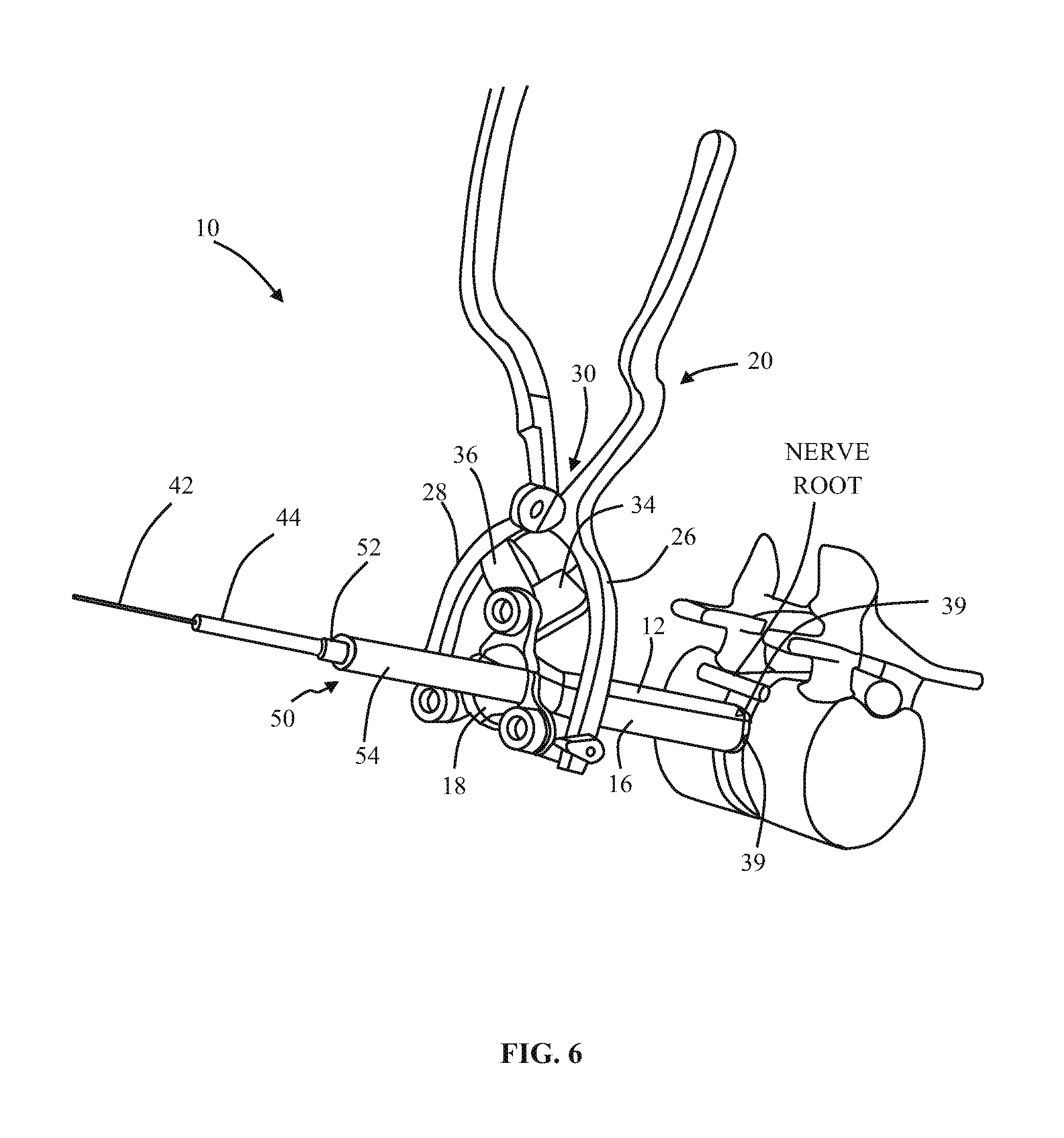
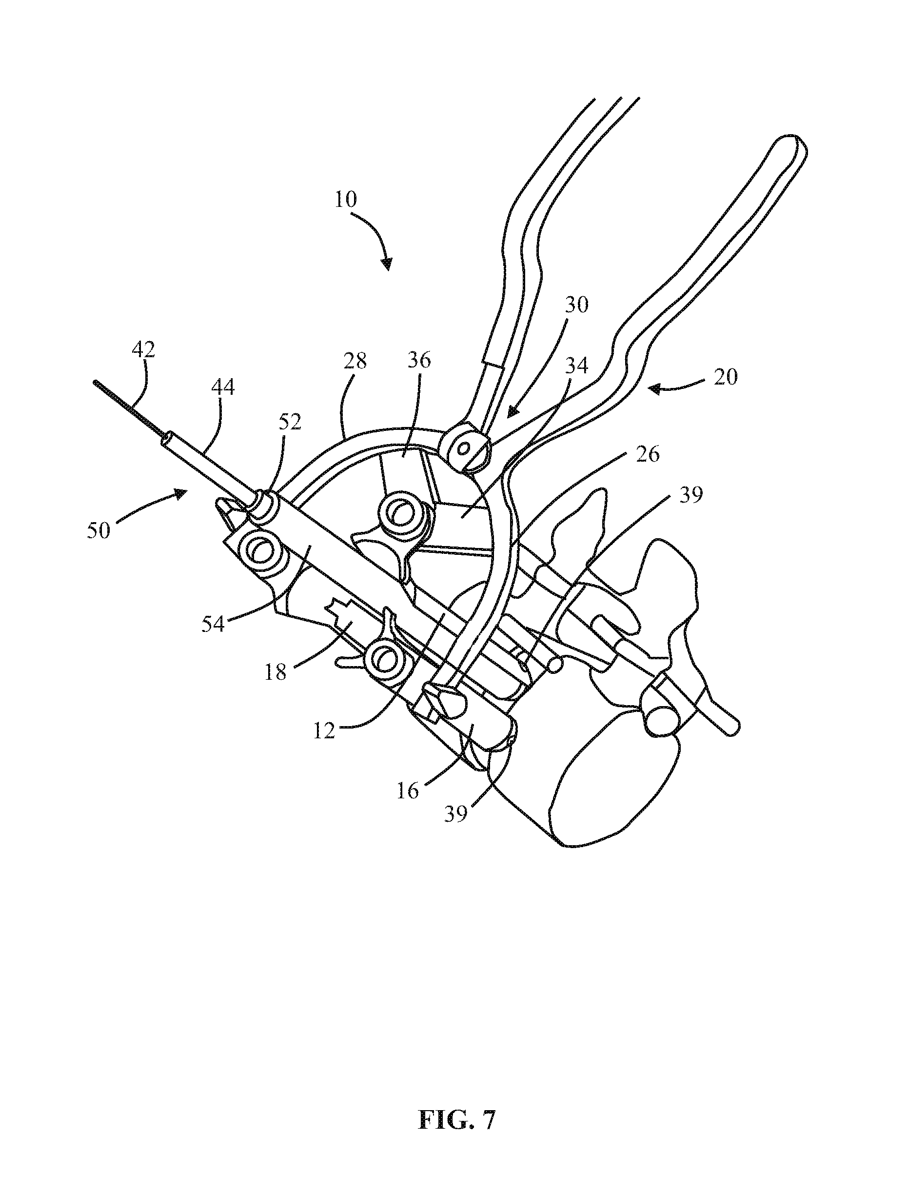
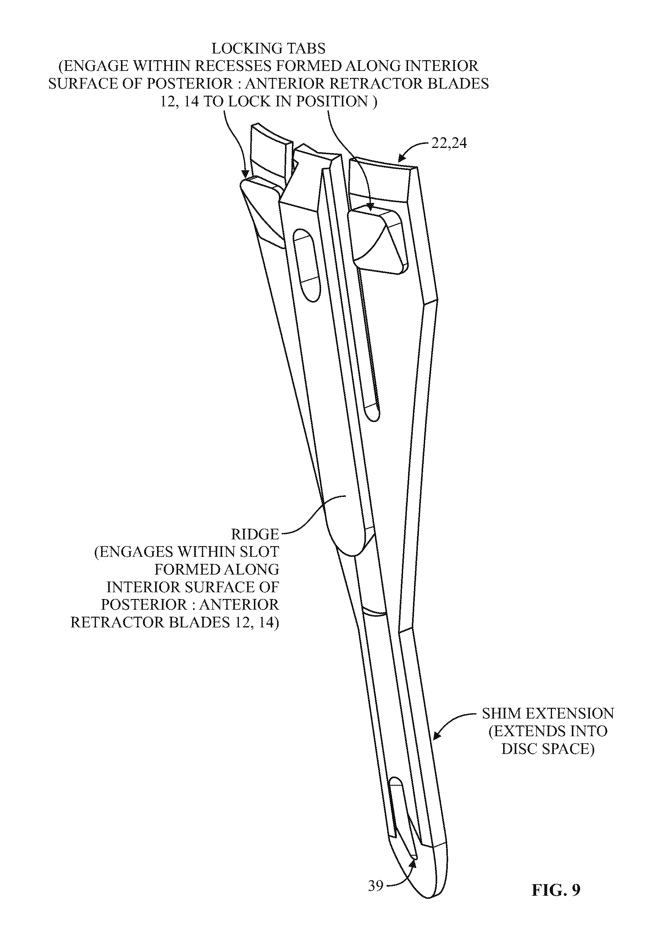
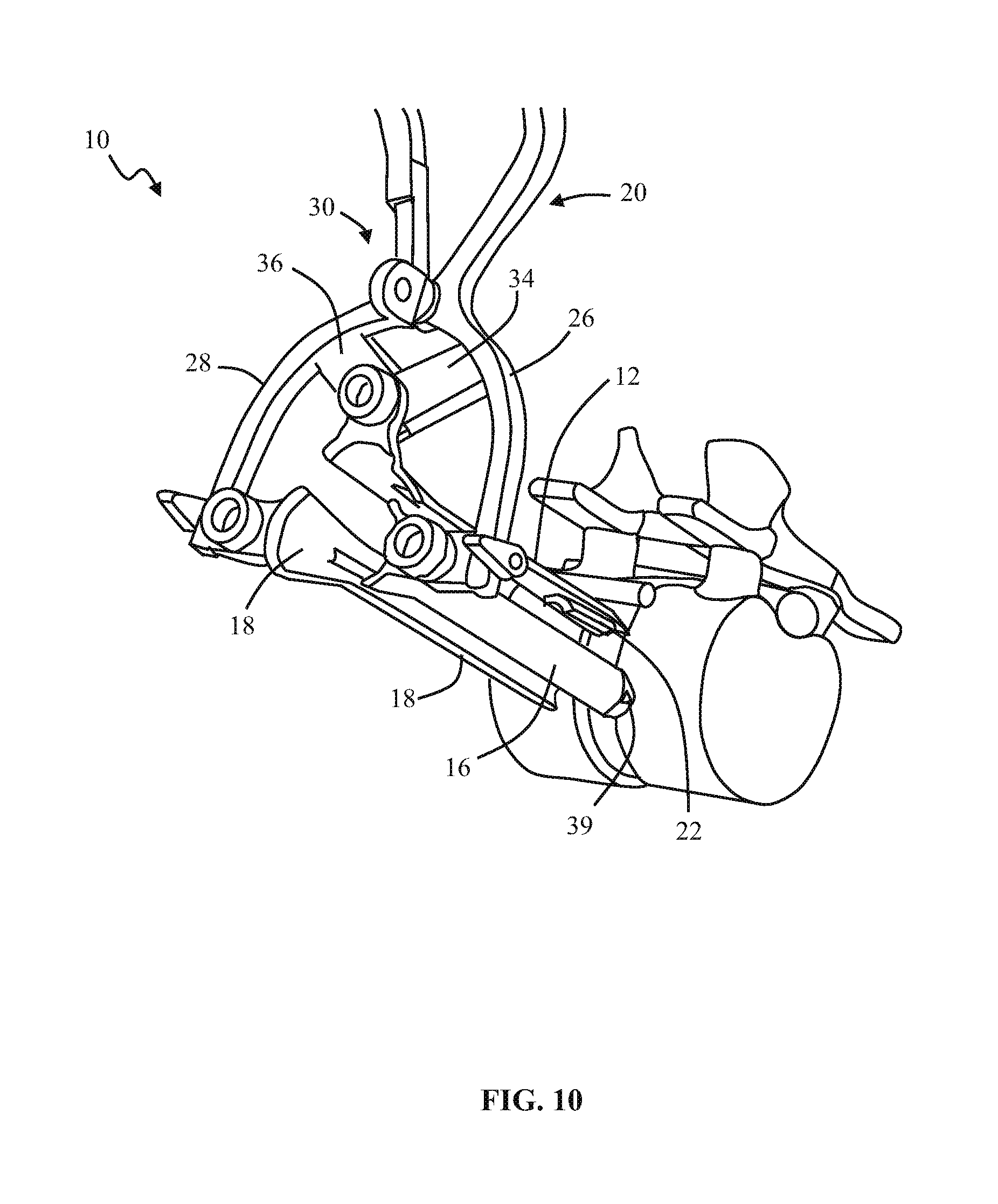
1. A method of forming an operating corridor to a lumbar spine of a patient, the patient having an anterior aspect, a posterior aspect and two lateral aspects, the method comprising: inserting a first sequential dilator of a plurality of sequential dilators into the patient at an insertion position on one of the two lateral aspects of the patient and advancing the first sequential dilator to a lateral aspect of a target intervertebral disc of the lumbar spine, a lateral, trans-psoas path having a path axis that extends from the insertion position on the one of the two lateral aspects to the other of the two lateral aspects of the patient, wherein a first stimulation electrode at a distal region of the first sequential dilator is configured to deliver electrical stimulation for nerve monitoring, the first sequential dilator comprising a first proximal connector portion for electrical connection with a nerve monitoring system; delivering electrical stimulation signals from the first stimulation electrode while the first sequential dilator is advanced along the lateral, trans-psoas path to detect and avoid directly contacting the nerves in the psoas muscle, advancing an elongate penetration member extending through the first sequential dilator into the target intervertebral disc, advancing a second sequential dilator of the plurality of sequential dilators over the first sequential dilator along the lateral, trans-psoas path to the targeted intervertebral disc of the lumbar spine; simultaneously delivering three retractor blades of a retractor assembly over an outermost dilator of the plurality of sequential dilators along the lateral, trans-psoas path, wherein the three retractor blades slide over the outermost dilator of the plurality of dilators in a closed position in which the three retractor blades are adjacent one another to form an enclosed corridor along the lateral trans-psoas path to the target intervertebral disc; positioning the retractor assembly such that the three retractor blades comprise a posterior retractor blade, a caudal retractor blade, and a cephalad retractor blade; removing the plurality of sequential dilators from the lateral aspect of the target intervertebral disc of the lumbar spine after the three retractor blades are positioned along the lateral, trans-psoas path; advancing a shim device along the posterior retractor blade to a position in which a portion of the shim device extends from the posterior retractor blade and into the target intervertebral disc; and adjusting the retractor assembly to move the caudal retractor blade and the cephalad retractor blade away from the posterior retractor blade to an open position such that the three retractor blades form a non-enclosed operating corridor to the target intervertebral disc of the lumbar spine that is dimensioned to pass an implant; and after adjusting the retractor assembly to form the operating corridor, passing an implant through the operative corridor along the lateral, trans-psoas path to the targeted intervertebral disc of the lumbar spine.
2. The method of claim 1, further comprising actuating a blade holder assembly of the retractor assembly to adjust the retractor assembly from the closed position to the open position.
3. The method of claim 2, wherein the three retractor blades extend generally perpendicularly relative to arm portions of the blade holder assembly.
4. The method of claim 1, wherein the elongate penetration member is delivered together with the first sequential dilator along the lateral, trans-psoas path.
5. The method of claim 4, wherein the elongate penetration member comprises a K-wire.
6. The method of claim 1, comprising the additional step of delivering a fourth retractor blade along the lateral, trans-psoas path after adjusting the retractor assembly to the open position and coupling the fourth retractor blade to the retractor assembly.
7. The method of claim 6, wherein the fourth retractor blade is positioned to be an anterior retractor blade along the lateral, trans-psoas path.
8. The method of claim 1, wherein the shim device includes a proximal portion configured to releasably attach to the posterior blade and a distal extension configured to extend distally of the posterior blade and penetrate into the target intervertebral disc space.
9. The method of claim 8, wherein the proximal portion includes a rearwardly extending ridge structure to releasably engage with a corresponding groove along an interior face of the posterior retractor blade when the shim device is advanced along the posterior retractor blade.
10. The method of claim 1, wherein the shim device has a maximum longitudinal length extending from a proximal-most end of the proximal portion to a distal-most end of the distal extension and extending parallel to a longitudinal axis of the shim device, wherein the maximum longitudinal length of the shim device is less than a maximum longitudinal length of the posterior retractor blade.
11. The method of claim 10, wherein the distal extension includes a maximum lateral width located proximally away from a distal-most end of the distal extension, the proximal portion having a proximal lateral width that is greater than the maximum lateral width of the distal extension.
12. The method of claim 11, wherein the distal-most end of the distal extension includes a tapered tip region.
13. The method of claim 1, wherein adjusting the retractor assembly includes pivoting a first pivot arm coupled to the cephalad retractor blade and pivoting a second pivot arm coupled to the caudal retractor blade.
14. The method of claim 1, comprising the additional step of delivering electrical stimulation signals from a second stimulation electrode at a distal region of the second sequential dilator while the second sequential dilator is advanced along the lateral, trans-psoas path to detect and avoid directly contacting the nerves in the psoas muscle, the second sequential dilator comprising a second proximal connector portion for electrical connection with a nerve monitoring system.
15. The method of claim 1, further comprising: electrically connecting a cable of the nerve monitoring system to the first proximal connector portion of the first sequential dilator, wherein the nerve monitoring system delivers an electrical stimulation signal to the first stimulation electrode of the first sequential dilator during advancement of the first sequential dilator along the lateral, trans-psoas path to the targeted intervertebral disc of the lumbar spine, the nerve monitoring system monitoring muscle activity detected by a set of sensor electrodes in communication with leg muscles associated with the nerves in the psoas muscle, and the nerve monitoring system displaying to a user a numeric stimulation current threshold required to obtain the detected muscle activity in at least one of said leg muscles during advancement of the first sequential dilator.
16. The method of claim 15, wherein the muscle activity is detected with electromyography (EMG) sensors.
Description
BACKGROUND OF THE INVENTION
I. Field of the Invention
The present invention relates generally to systems and methods for performing surgical procedures and, more particularly, for accessing a surgical target site in order to perform surgical procedures.
II. Discussion of the Prior Art
A noteworthy trend in the medical community is the move away from performing surgery via traditional "open" techniques in favor of minimally invasive or minimal access techniques. Open surgical techniques are generally undesirable in that they typically require large incisions and high amounts of tissue displacement to gain access to the surgical target site, which produces concomitantly high amounts of pain, lengthened hospitalization (increasing health care costs), and high morbidity in the patient population. Less-invasive surgical techniques (including so-called "minimal access" and "minimally invasive" techniques) are gaining favor due to the fact that they involve accessing the surgical target site via incisions of substantially smaller size with greatly reduced tissue displacement requirements. This, in turn, reduces the pain, morbidity and cost associated with such procedures. The access systems developed to date, however, fail in various respects to meet all the needs of the surgeon population.
One drawback associated with prior art surgical access systems relates to the ease with which the operative corridor can be created, as well as maintained over time, depending upon the particular surgical target site. For example, when accessing surgical target sites located beneath or behind musculature or other relatively strong tissue (such as, by way of example only, the psoas muscle adjacent to the spine), it has been found that advancing an operative corridor-establishing instrument directly through such tissues can be challenging and/or lead to unwanted or undesirable effects (such as stressing or tearing the tissues). While certain efforts have been undertaken to reduce the trauma to tissue while creating an operative corridor, such as (by way of example only) the sequential dilation system of U.S. Pat. No. 5,792,044 to Foley et al., these attempts are nonetheless limited in their applicability based on the relatively narrow operative corridor. More specifically, based on the generally cylindrical nature of the so-called "working cannula," the degree to which instruments can be manipulated and/or angled within the cannula can be generally limited or restrictive, particularly if the surgical target site is a relatively deep within the patient.
Efforts have been undertaken to overcome this drawback, such as shown in U.S. Pat. No. 6,524,320 to DiPoto, wherein an expandable portion is provided at the distal end of a cannula for creating a region of increased cross-sectional area adjacent to the surgical target site. While this system may provide for improved instrument manipulation relative to sequential dilation access systems (at least at deep sites within the patient), it is nonetheless flawed in that the deployment of the expandable portion may inadvertently compress or impinge upon sensitive tissues adjacent to the surgical target site. For example, in anatomical regions having neural and/or vasculature structures, such a blind expansion may cause the expandable portion to impinge upon these sensitive tissues and cause neural and/or vasculature compromise, damage and/or pain for the patient.
This highlights yet another drawback with the prior art surgical access systems, namely, the challenges in establishing an operative corridor through or near tissue having major neural structures which, if contacted or impinged, may result in neural impairment for the patient. Due to the threat of contacting such neural structures, efforts thus far have largely restricted to establishing operative corridors through tissue having little or substantially reduced neural structures, which effectively limits the number of ways a given surgical target site can be accessed. This can be seen, by way of example only, in the spinal arts, where the exiting nerve roots and neural plexus structures in the psoas muscle have rendered a lateral or far lateral access path (so-called trans-psoas approach) to the lumbar spine virtually impossible. Instead, spine surgeons are largely restricted to accessing the spine from the posterior (to perform, among other procedures, posterior lumbar interbody fusion (PLIF)) or from the anterior (to perform, among other procedures, anterior lumbar interbody fusion (ALIF)).
Posterior-access procedures involve traversing a shorter distance within the patient to establish the operative corridor, albeit at the price of oftentimes having to reduce or cut away part of the posterior bony structures (i.e. lamina, facets, spinous process) in order to reach the target site (which typically comprises the disc space). Anterior-access procedures are relatively simple for surgeons in that they do not involve reducing or cutting away bony structures to reach the surgical target site. However, they are nonetheless disadvantageous in that they require traversing through a much greater distance within the patient to establish the operative corridor, oftentimes requiring an additional surgeon to assist with moving the various internal organs out of the way to create the operative corridor.
The present invention is directed at eliminating, or at least minimizing the effects of, the above-identified drawbacks in the prior art.
SUMMARY OF THE INVENTION
The present invention accomplishes this goal by providing a novel access system and related methods which, according to one embodiment, involves detecting the existence of (and optionally the distance and/or direction to) neural structures before, during, and after the establishment of an operative corridor through (or near) any of a variety of tissues having such neural structures which, if contacted or impinged, may otherwise result in neural impairment for the patient. It is expressly noted that, although described herein largely in terms of use in spinal surgery, the access system of the present invention is suitable for use in any number of additional surgical procedures wherein tissue having significant neural structures must be passed through (or near) in order to establish an operative corridor.
The present invention accomplishes this goal by providing a novel access system and related methods which involve: (1) distracting the tissue between the patient's skin and the surgical target site to create an area of distraction (otherwise referred to herein as a "distraction corridor"); (2) retracting the distraction corridor to establish and maintain an operative corridor; and/or (3) detecting the existence of (and optionally the distance and/or direction to) neural structures before, during and after the establishment of the operative corridor through (or near) any of a variety of tissues having such neural structures which, if contacted or impinged, may otherwise result in neural impairment for the patient.
As used herein, "distraction" or "distracting" is defined as the act of creating a corridor (extending to a location at or near the surgical target site) having a certain cross-sectional area and shape ("distraction corridor"), and "retraction" or "retracting" is defined as the act of creating an operative corridor by increasing or maintaining the cross-sectional area of the distraction corridor (and/or modifying its shape) with at least one retractor blade such that surgical instruments can be passed through operative corridor to the surgical target site.
According to one broad aspect of the present invention, the access system comprises a tissue distraction assembly and a tissue retraction assembly, both of which may be equipped with one or more electrodes for use in detecting the existence of (and optionally the distance and/or direction to) neural structures during the steps tissue distraction and/or retraction. To accomplish this, one or more stimulation electrodes are provided on the various components of the distraction assemblies and/or retraction assemblies, a stimulation source (e.g. voltage or current) is coupled to the stimulation electrodes, a stimulation signal is emitted from the stimulation electrodes as the various components are advanced towards the surgical target site, and the patient is monitored to determine if the stimulation signal causes muscles associated with nerves or neural structures within the tissue to innervate. If the nerves innervate, this indicates that neural structures may be in close proximity to the distraction and/or retraction assemblies.
This monitoring may be accomplished via any number of suitable fashions, including but not limited to observing visual twitches in muscle groups associated with the neural structures likely to found in the tissue, as well as any number of monitoring systems. In either situation (traditional EMG or surgeon-driven EMG monitoring), the access system of the present invention may advantageously be used to traverse tissue that would ordinarily be deemed unsafe or undesirable, thereby broadening the number of manners in which a given surgical target site may be accessed.
The tissue distraction assembly is capable of, as an initial step, distracting a region of tissue between the skin of the patient and the surgical target site. The tissue retraction assembly is capable of, as a secondary step, being introduced into this distracted region to thereby define and establish the operative corridor. Once established, any of a variety of surgical instruments, devices, or implants may be passed through and/or manipulated within the operative corridor depending upon the given surgical procedure. The electrode(s) are capable of, during both tissue distraction and retraction, detecting the existence of (and optionally the distance and/or direction to) neural structures such that the operative corridor may be established through (or near) any of a variety of tissues having such neural structures which, if contacted or impinged, may otherwise result in neural impairment for the patient. In this fashion, the access system of the present invention may be used to traverse tissue that would ordinarily be deemed unsafe or undesirable, thereby broadening the number of manners in which a given surgical target site may be accessed.
The tissue distraction assembly may include any number of components capable of performing the necessary distraction. By way of example only, the tissue distraction assembly may include a K-wire, an initial dilator (of split construction or traditional non-slit construction), and one or more dilators of traditional (that is, non-split) construction for performing the necessary tissue distraction to receive the remainder of the tissue retractor assembly thereafter. One or more electrodes may be provided on one or more of the K-wire and dilator(s) to detect the presence of (and optionally the distance and/or direction to) neural structures during tissue distraction.
The tissue retraction assembly may include any number of components capable of performing the necessary retraction. By way of example only, the tissue retraction assembly may include one or more retractor blades extending proximally from the surgical target site for connection with a pivot linkage assembly. The pivot linkage includes first and second pivot arms capable of maintaining the retractor blades in a first, closed position to facilitate the introduction of the retractor blades over the distraction assembly. Thereafter, the pivot linkage may be manipulated to open the retractor assembly; that is, allowing the retractor blades to separate from one another (preferably simultaneously) to create an operative corridor to the surgical target site. In a preferred embodiment, this is accomplished by maintaining a posterior retractor blade in a fixed position relative to the surgical target site (so as to avoid having it impinge upon any exiting nerve roots near the posterior elements of the spine) while the additional retractor blades (i.e. cephalad, caudal and/or anterior retractor blades) are moved or otherwise translated away from the posterior retractor blade (and each other) so as to create the operative corridor in a fashion that doesn't infringe upon the region of the exiting nerve roots. This is accomplished, in part, through the use of a secondary pivot linkage coupled to the pivot linkage assembly, which allows the posterior retractor blade to remain in a constant position while the other retractor blades are moved. In one embodiment, the anterior retractor blade may be positioned after the posterior, cephalad, and caudal retractor blades are positioned into the fully retracted position. This may be accomplished by coupling the anterior retractor blade to the pivot linkage via an arm assembly.
The retractor blades may be optionally dimensioned to receive and direct a rigid shim element to augment the structural stability of the retractor blades and thereby ensure the operative corridor, once established, will not decrease or become more restricted, such as may result if distal ends of the retractor blades were permitted to "slide" or otherwise move in response to the force exerted by the displaced tissue. In a preferred embodiment, only the posterior and anterior retractor blades are equipped with such rigid shim elements, which are advanced into the disc space after the posterior and anterior retractor blades are positioned (posterior first, followed by anterior after the cephalad, caudal and anterior blades are moved into the fully retracted position). The rigid shim elements are preferably oriented within the disc space such that they distract the adjacent vertebral bodies, which serves to restore disc height. They are also preferably advanced a sufficient distance within the disc space (preferably past the midline), which serves the dual purpose of preventing post-operative scoliosis and forming a protective barrier (preventing the migration of tissue (such as nerve roots) into the operative field and the inadvertent advancement of instruments outside the operative field).
The retractor blades may optionally be equipped with a mechanism for transporting or emitting light at or near the surgical target site to aid the surgeon's ability to visualize the surgical target site, instruments and/or implants during the given surgical procedure. According to one embodiment, this mechanism may comprise, but need not be limited to, providing one or more strands of fiber optic cable within the walls of the retractor blades such that the terminal (distal) ends are capable of emitting light at or near the surgical target site. According to another embodiment, this mechanism may comprise, but need not be limited to, constructing the retractor blades of suitable material (such as clear polycarbonate) and configuration such that light may be transmitted generally distally through the walls of the retractor blade light to shine light at or near the surgical target site. This may be performed by providing the retractor blades having light-transmission characteristics (such as with clear polycarbonate construction) and transmitting the light almost entirely within the walls of the retractor blade (such as by frosting or otherwise rendering opaque portions of the exterior and/or interior) until it exits a portion along the interior (or medially-facing) surface of the retractor blade to shine at or near the surgical target site. The exit portion may be optimally configured such that the light is directed towards the approximate center of the surgical target site and may be provided along the entire inner periphery of the retractor blade or one or more portions therealong.
BRIEF DESCRIPTION OF THE DRAWINGS
Many advantages of the present invention will be apparent to those skilled in the art with a reading of this specification in conjunction with the attached drawings, wherein like reference numerals are applied to like elements and wherein:
FIG. 1 is a perspective view of a tissue retraction assembly (in use) forming part of a surgical access system according to the present invention;
FIG. 2 is a perspective view illustrating the components and use of an initial distraction assembly (i.e. K-wire, an initial dilating cannula with handle, and a split-dilator housed within the initial dilating cannula) forming part of the surgical access system according to the present invention, for use in distracting to a surgical target site (i.e. annulus);
FIG. 3 is a perspective view illustrating the K-wire and split-dilator of the initial distraction assembly with the initial dilating cannula and handle removed;
FIG. 4 is a posterior view of the vertebral target site illustrating the split-dilator of the present invention in use distracting in a generally cephalad-caudal fashion according to one aspect of the present invention;
FIG. 5 is a side view illustrating the use of a secondary distraction assembly (comprising a plurality of dilating cannulae over the K-wire) to further distract tissue between the skin of the patient and the surgical target site according to the present invention;
FIG. 6 is a perspective view of a retractor assembly according to the present invention, comprising a linkage assembly having three (3) retractor blades coupled thereto (posterior, cephalad, and caudal) for the purpose of creating an operative corridor to the surgical target site (shown in a first, closed position);
FIG. 7 is a perspective view of the retractor assembly of FIG. 6 in a second, opened (i.e. retracted) position according to the present invention;
FIG. 8 is a perspective view illustrating a shim introducer introducing a shim element along the interior of the posterior retractor blade such that a distal portion (shim extension) is positioned within the disc space;
FIG. 9 is a back view of a shim element according to the present invention dimensioned to be engaged with the inner surface of the posterior (and optionally anterior) retractor blade for the purpose of positioning a shim extension within the disc space, such as via the shim introducer shown in FIG. 8;
FIG. 10 is a perspective view of the retractor assembly of the present invention with the shim element disposed along the posterior retractor blade according to the present invention;
FIGS. 11-12 are perspective views of the retractor assembly of the present invention, wherein an anterior retractor blade is provided coupled to the linkage assembly via an arm assembly;
FIG. 13 is a perspective view of the retractor assembly of the present invention wherein a shim introducer is employed to introducer a shim along the anterior retractor blade according to the present invention;
FIG. 14 is a perspective view of the retractor assembly of the present invention, wherein the anterior retractor blade may be positioned at a different vertical level than the posterior, cephalad, and caudal retractor blades according to the present invention;
FIG. 15 is a perspective view of an exemplary nerve monitoring system capable of performing nerve monitoring before, during and after the creating of an operative corridor to a surgical target site using the surgical access system in accordance with the present invention;
FIG. 16 is a block diagram of the nerve monitoring system shown in FIG. 15; and
FIGS. 17-18 are screen displays illustrating exemplary features and information communicated to a user during the use of the nerve monitoring system of FIG. 15.
DESCRIPTION OF THE PREFERRED EMBODIMENT
Illustrative embodiments of the invention are described below. In the interest of clarity, not all features of an actual implementation are described in this specification. It will of course be appreciated that in the development of any such actual embodiment, numerous implementation-specific decisions must be made to achieve the developers' specific goals, such as compliance with system-related and business-related constraints, which will vary from one implementation to another. Moreover, it will be appreciated that such a development effort might be complex and time-consuming, but would nevertheless be a routine undertaking for those of ordinary skill in the art having the benefit of this disclosure. It is furthermore to be readily understood that, although discussed below primarily within the context of spinal surgery, the surgical access system of the present invention may be employed in any number of anatomical settings to provide access to any number of different surgical target sites throughout the body. The surgical access system disclosed herein boasts a variety of inventive features and components that warrant patent protection, both individually and in combination.
It is furthermore to be readily understood that, although discussed below primarily within the context of spinal surgery, the surgical access system and related methods of the present invention may find applicability in any of a variety of surgical and/or medical applications such that the following description relative to the spine is not to be limiting of the overall scope of the present invention. Moreover, while described below employing the nerve monitoring features described above (otherwise referred to as "nerve surveillance") during spinal surgery, it will be appreciated that such nerve surveillance will not be required in all situations, depending upon the particular surgical target site (e.g. disk space, vertebral body, and/or internal organ), surgical approach (e.g. lateral, posterior, anterior, and/or postero-lateral approaches to the spine), and spinal level (e.g. cervical, thoracic and/or lumbar).
The present invention is directed at a novel surgical access system and related methods which involve creating and maintaining an operative corridor to the surgical target site, and optionally detecting the existence of (and optionally the distance and/or direction to) neural structures before, during and/or after this process (including the steps of distraction and/or retraction). This is accomplished by employing the following steps: (1) one or more stimulation electrodes are provided on the various distraction and/or retraction components; (2) a stimulation source (e.g. voltage or current) is coupled to the stimulation electrodes; (3) a stimulation signal is emitted from the stimulation electrodes as the various components are advanced towards or maintained at or near the surgical target site; and (4) the patient is monitored to determine if the stimulation signal causes muscles associated with nerves or neural structures within the tissue to innervate. If the nerves innervate, this may indicate that neural structures may be in close proximity to the distraction and/or retraction components.
Neural monitoring may be accomplished via any number of suitable fashions, including but not limited to observing visual twitches in muscle groups associated with the neural structures likely to found in the tissue, as well as any number of monitoring systems, including but not limited to any commercially available "traditional" electromyography (EMG) system (that is, typically operated by a neurophysiologist. Such monitoring may also be carried out via the surgeon-driven EMG monitoring system shown and described in the following commonly owned and co-pending "NeuroVision Applications" incorporated by reference into this disclosure above. In any case (visual monitoring, traditional EMG and/or surgeon-driven EMG monitoring), the access system of the present invention may advantageously be used to traverse tissue that would ordinarily be deemed unsafe or undesirable, thereby broadening the number of manners in which a given surgical target site may be accessed.
Distraction followed by retraction is advantageous because it provides the ability to more easily position an operative corridor-establishing device through tissue that is strong, thick or otherwise challenging to traverse in order to access a surgical target site. The various distraction systems of the present invention are advantageous in that they provide an improved manner of atraumatically establishing a distraction corridor prior to the use of the retraction systems of the present invention. The various retractor systems of the present invention are advantageous in that they provide an operative corridor having improved cross-sectional area and shape (including customization thereof) relative to the prior art surgical access systems. Moreover, by optionally equipping the various distraction systems and/or retraction systems with one or more electrodes, an operative corridor may be established through (or near) any of a variety of tissues having such neural structures which, if contacted or impinged, may otherwise result in neural impairment for the patient.
The present invention involves accessing a surgical target site in a fashion less invasive than traditional "open" surgeries and doing so in a manner that provides access in spite of the neural structures required to be passed through (or near) in order to establish an operative corridor to the surgical target site. Generally speaking, the surgical access system of the present invention accomplishes this by providing a tissue distraction assembly and a tissue retraction assembly, both of which may be equipped with one or more electrodes for use in detecting the existence of (and optionally the distance and/or direction to) neural structures.
These electrodes are preferably provided for use with a nerve surveillance system such as, by way of example, the type shown and described in co-pending and commonly assigned NeuroVision PCT Applications incorporated by reference above. Generally speaking, this nerve surveillance system is capable of detecting the existence of (and optionally the distance and/or direction to) neural structures during the distraction and retraction of tissue by detecting the presence of nerves by applying a stimulation signal to such instruments and monitoring the evoked EMG signals from the myotomes associated with the nerves being passed by the distraction and retraction systems of the present invention. In so doing, the system as a whole (including the surgical access system of the present invention) may be used to form an operative corridor through (or near) any of a variety of tissues having such neural structures, particularly those which, if contacted or impinged, may otherwise result in neural impairment for the patient. In this fashion, the access system of the present invention may be used to traverse tissue that would ordinarily be deemed unsafe or undesirable, thereby broadening the number of manners in which a given surgical target site may be accessed.
The tissue distraction assembly of the present invention (comprising a K-wire, an initial dilator, and a split-dilator disposed within the initial dilator) is employed to distract the tissues extending between the skin of the patient and a given surgical target site (preferably along the posterior region of the target intervertebral disc). A secondary distraction assembly (i.e. a plurality of sequentially dilating cannulae) may optionally be employed after the initial distraction assembly to further distract the tissue. Once distracted, the resulting void or distracted region within the patient is of sufficient size to accommodate a tissue retraction assembly of the present invention. More specifically, the tissue retraction assembly (comprising a plurality of retractor blades coupled to a linkage assembly) may be advanced relative to the secondary distraction assembly such that the retractor blades, in a first, closed position, are advanced over the exterior of the secondary distraction assembly. At that point, the linkage assembly may be operated to move the retractor blades into a second, open or "retracted" position to create an operative corridor to the surgical target site.
According to one aspect of the invention, following (or before) this retraction, a posterior shim element (which is preferably slideably engaged with the posterior retractor blade) may be advanced such that a shim extension in positioned within the posterior region of the disc space. If done before retraction, this helps ensure that the posterior retractor blade will not move posteriorly during the retraction process, even though the other retractor blades (i.e. cephalad, caudal, and/or anterior retractor blades) are able to move and thereby create an operative corridor. Fixing the posterior retractor blade in this fashion helps prevent inadvertent contact with the existing nerve roots in the posterior region of the spine. The posterior shim element also helps ensure that surgical instruments employed within the operative corridor are incapable of being advanced outside the operative corridor, yet again preventing inadvertent contact with the exiting nerve roots during the surgery. Once in the appropriate anterior position, the anterior retractor blade may be locked in position and, thereafter, an anterior shim element advanced therealong for positioning a shim extension within the anterior of the disc space.
The shim elements serve to distract the adjacent vertebral bodies (thereby restoring disc height), to form protective barriers (against the migration of tissue into (or instruments out of) the operative site), and to rigidly couple the posterior and anterior retractor blades in fixed relation relative to the vertebral bodies. Once the operative corridor is established, any of a variety of surgical instruments, devices, or implants may be passed through and/or manipulated within the operative corridor depending upon the given surgical procedure.
FIG. 1 illustrates a tissue retraction assembly 10 forming part of a surgical access system according to the present invention. The retraction assembly 10 includes a posterior retractor blade 12, an anterior retractor blade 14, cephalad retractor blade 16, and caudal retractor blade 18, all of which are coupled to a linkage assembly 20. Posterior and anterior retractor blades 12, 14 establish an AP (or "width") dimension of an operative corridor 15. Posterior retractor blade 12 and anterior retractor blade 14 are equipped with shim elements 22, 24, respectively (shown more clearly in FIG. 9). Shim elements 22, 24 serve to distract the adjacent vertebral bodies (thereby restoring disc height), form protective barriers (against the migration of tissue into (or instruments out of) the operative site), and rigidly couple the posterior and anterior retractor blades 12, 14 in fixed relation relative to the vertebral bodies. Cephalad and caudal retractor blades 16, 18 establish and maintain the "height" dimension of the operative corridor 15. Each retractor blade 12-18 (and optionally the shim elements 22, 24) may be, according to the present invention, provided with one or more electrodes 39 (preferably at their distal regions) equipped for use with a nerve surveillance system, such as, by way of example, the type shown and described in the NeuroVision PCT Applications.
The linkage assembly 20 may be coupled to any number of mechanisms for rigidly registering the linkage assembly 20 in fixed relation to the operative site, such as through the use of an articulating arm mounted to the operating table. The linkage assembly 20 includes first and second arm members 26, 28 hingedly coupled at 30. The cephalad retractor blade 16 is rigidly coupled (generally perpendicularly) to the end of the first arm member 26. The caudal retractor blade 18 is rigidly coupled (generally perpendicularly) to the end of the second arm member 28. The posterior retractor blade 12 is coupled to the linkage assembly 20 via a pivot linkage 32 (comprising a first arm 34 hingedly disposed between the posterior retractor blade 12 and the first arm member 26, and a second arm 26 hingedly disposed between the posterior retractor blade 12 and the second arm 28) such that the posterior retractor blade 12 will have a tendency to remain in the same position during the retraction process. According to one embodiment, the anterior retractor blade 14 may be coupled to the linkage assembly 20 via an arm assembly 38.
FIG. 2 illustrates an initial distraction assembly 40 forming part of the surgical access system according to the present invention. The initial distraction assembly 40 includes a K-wire 42, an initial dilating cannula 44 with handle 46, and a split-dilator 48 housed within the initial dilating cannula 44. In use, the K-wire 42 and split-dilator 48 are disposed within the initial dilating cannula 44 and the entire assembly 40 advanced through the tissue towards the surgical target site (i.e. annulus). Again, this is preferably accomplished while employing the nerve detection and/or direction features described above. After the initial dilating assembly 40 is advanced such that the distal ends of the split-dilator 48 and initial dilator 44 are positioned within the disc space (FIG. 2), the initial dilator 44 and handle 46 are removed (FIG. 3) to thereby leave the split-dilator 48 and K-wire 42 in place. As shown in FIG. 4, the split-dilator 48 is thereafter split such that the respective halves 48a, 48b are separated from one another to distract tissue in a generally cephalad-caudal fashion relative to the target site. The split dilator 48 may thereafter be relaxed (allowing the dilator halves 48a, 48b to come together) and rotated such that the dilator halves 48a, 48b are disposed in the anterior-posterior plane. Once rotated in this manner, the dilator halves 48a, 48b are again separated to distract tissue in a generally anterior-posterior fashion. Each dilator halve 48a, 48b may be, according to the present invention, provided with one or more electrodes (preferably at their distal regions) equipped for use with a nerve surveillance system, such as, by way of example, the type shown and described in the NeuroVision PCT Applications.
Following this initial distraction, a secondary distraction may be optionally undertaken, such as via a sequential dilation system 50 as shown in FIG. 5. According to the present invention, the sequential dilation system 50 may include the K-wire 42, the initial dilator 44, and one or more supplemental dilators 52, 54 for the purpose of further dilating the tissue down to the surgical target site. Once again, each component of the secondary distraction assembly 50 (namely, the K-wire 42, the initial dilator 44, and the supplemental dilators 52, 54 may be, according to the present invention, provided with one or more electrodes (preferably at their distal regions) equipped for use with a nerve surveillance system, such as, by way of example, the type shown and described in the NeuroVision PCT Applications.
As shown in FIG. 6, the retraction assembly 10 of the present invention is thereafter advanced along the exterior of the sequential dilation system 50. This is accomplished by maintaining the retractor blades 12-16 in a first, closed position (with the retractor blades 12-16 in generally abutting relation to one another). Once advanced to the surgical target site, the linkage assembly 20 may be operated as shown in FIG. 7 to move the retractor blades 12-16 into a second, open or "retracted" position. As one can see, the posterior retractor blade 12 is allowed to stay in the same general position during this process, such that the cephalad and caudal retractor blades 14, 16 move away from the posterior retractor blade 12. Again, this is accomplished through the use of the pivot linkage 32 between the posterior retractor blade 12 and the arms 26, 28 of the linkage assembly 20.
At this point, as shown in FIG. 8, the posterior shim element 22 (FIG. 9) may be advanced along an engagement slot formed along the interior surface of the posterior retractor blade 12 such that the shim extension (distal end) is positioned in the posterior region of the disc space as shown in FIG. 10. To aid in this process, a shim introducer 60 may be provided, which includes a handle member 62 and an elongate portion 64 capable of delivering the shim element 22 along the interior of the posterior retractor blade 12 and thereafter selectively disengaging the shim element 22 so as to remove the elongate portion 64 from the operative site. As shown in FIGS. 11-12, the anterior retractor blade 14 may thereafter be positioned relative to the posterior, cephalad, and caudal retractor blades 12, 16, 18, respectively, by virtue of the arm assembly 38. The anterior shim element 24 may thereafter be advanced along the anterior retractor blade 14 such that the shim extension (distal region thereof) extends into the anterior region of the disc space as shown in FIG. 13. The end result is shown in FIG. 14, with the retraction assembly 10 of the present invention disposed in position over a surgical target site.
FIGS. 15-16 illustrate, by way of example only, a surgical system 120 provided in accordance with a broad aspect of the present invention. The surgical system 120 includes a control unit 122, a patient module 124, an EMG harness 126 and return electrode 128 coupled to the patient module 124, and an accessory cable 132 in combination with a handle assembly 136. The handle assembly 136 includes one or more electrical connectors 130, including (by way of example only) a pin connector 134, a pin connector 138, and a clamping-style connector 135. As shown in dotted lines, each of the electrical connectors 130 may be coupled to the handle assembly 136 and include a manner of establishing electrical communications with any of the electrodes 39 provided on the distraction and/or retraction assemblies of the present invention, including the shims 22, 24 (collectively "Surgical Access Instruments"). By establishing electrical communication in this fashion, the handle assembly 136 may be employed to selectively apply a stimulation signal to any of the Surgical Access Instruments to detect the presence of (and optionally direction to) neural structures during and/or after the distraction and retraction steps of the present invention.
The control unit 122 includes a touch screen display 140 and a base 142, which collectively contain the essential processing capabilities for controlling the surgical system 120. The patient module 124 is connected to the control unit 122 via a data cable 144, which establishes the electrical connections and communications (digital and/or analog) between the control unit 122 and patient module 124. The main functions of the control unit 122 include receiving user commands via the touch screen display 140, activating stimulation, processing signal data according to defined algorithms (described below), displaying received parameters and processed data, and monitoring system status and reporting fault conditions. The touch screen display 140 is preferably equipped with a graphical user interface (GUI) capable of communicating information to the user and receiving instructions from the user. The display 140 and/or base 142 may contain patient module interface circuitry that commands the stimulation sources, receives digitized signals and other information from the patient module 124, processes the EMG responses to extract characteristic information for each muscle group, and displays the processed data to the operator via the display 140.
The accessory handle assembly 136 includes a cable 155 for establishing electrical communication with the patient module 124 (via the accessory cable 132). In a preferred embodiment, each electrical connector 130 includes a proximal electrical connector 156 and an electrical cable 157 for establishing electrical communication between the handle assembly 136 and the electrical connectors 134, 138, and 135. The proximal electrical connector 156 may be designed to thread and/or snap into engagement with the distal end 159 of the handle assembly 136. In this fashion, the Surgical Access Instruments may be quickly and easily coupled (electrically and mechanically) to the accessory handle assembly 136. The pin connectors 134 and 138 may be designed to engage with electrical mating portions provided on the Surgical Access Instruments, wherein these electrical mating portions are in turn electrically coupled to the electrodes 39. The distal electrical connector of the clamp-type coupler 135 may include any number of suitable electrode or electrode regions (including protrusions) on or about the distal (or pinching) ends of the clamp arms 161 forming the coupler 135. Corresponding regions (such as electrodes or electrode regions--including indentations) may be provided on the Surgical Access Instruments (including K-wire 42) according to the present invention.
In all situations, the user may operate one or more buttons of the handle assembly 136 to selectively initiate a stimulation signal (preferably, a current signal) from the patient module 124 to one of the electrical connectors 130, and hence the electrodes 39 on the distraction and retraction assemblies of the present invention. By monitoring the myotomes associated with the nerve roots (via the EMG harness 126 and recording electrode 127) and assessing the resulting EMG responses (via the control unit 122), the surgical system 120 can detect the presence of (and optionally the direction to) neural structures during and after the distraction and/or retraction according to the present invention.
In one embodiment, the monitoring system 120 is capable of determining nerve presence and/or direction relative to one or more of the K-wire 42, dilating cannula 44, split-retractor 48, retractor blades 12-18, and/or the shim elements 22, 24 before, during and/or following the creation of an operative corridor to a surgical target site. Monitoring system 120 accomplishes this by having the control unit 122 and patient module 124 cooperate to send electrical stimulation signals to one or more of the stimulation electrodes provided on these Surgical Access Instruments. Depending upon the location within a patient (and more particularly, to any neural structures), the stimulation signals may cause nerves adjacent to or in the general proximity of the Surgical Access Instruments to depolarize. This causes muscle groups to innervate and generate EMG responses, which can be sensed via the EMG harness 126. The nerve direction feature of the system 120 is based on assessing the evoked response of the various muscle myotomes monitored by the system 120 via the EMG harness 126.
By monitoring the myotomes associated with the nerves (via the EMG harness 126 and recording electrode 127) and assessing the resulting EMG responses (via the control unit 122), the surgical access system of the present invention is capable of detecting the presence of (and optionally the distant and/or direction to) such nerves. This provides the ability to actively negotiate around or past such nerves to safely and reproducibly form the operative corridor to a particular surgical target site, as well as monitor to ensure that no neural structures migrate into contact with the retraction assembly 10 after the operative corridor has been established. In spinal surgery, for example, this is particularly advantageous in that the surgical access system of the present invention may be particularly suited for establishing an operative corridor to an intervertebral target site in a postero-lateral, trans-psoas fashion so as to avoid the bony posterior elements of the spinal column.
FIGS. 17-18 are exemplary screen displays (to be shown on the display 140) illustrating one embodiment of the nerve direction feature of the monitoring system shown and described with reference to FIGS. 15-16. These screen displays are intended to communicate a variety of information to the surgeon in an easy-to-interpret fashion. This information may include, but is not necessarily limited to, a display of the function 180 (in this case "DIRECTION"), a graphical representation of a patient 181, the myotome levels being monitored 182, the nerve or group associated with a displayed myotome 183, the name of the instrument being used 184 (e.g. dilating cannula 44), the size of the instrument being used 185, the stimulation threshold current 186, a graphical representation of the instrument being used 187 (in this case, a cross-sectional view of a dilating cannula 44) to provide a reference point from which to illustrate relative direction of the instrument to the nerve, the stimulation current being applied to the stimulation electrodes 188, instructions for the user 189 (in this case, "ADVANCE" and/or "HOLD"), and (in FIG. 19) an arrow 190 indicating the direction from the instrument to a nerve. This information may be communicated in any number of suitable fashions, including but not limited to the use of visual indicia (such as alpha-numeric characters, light-emitting elements, and/or graphics) and audio communications (such as a speaker element). Although shown with specific reference to a dilating cannula (such as at 184), it is to be readily appreciated that the present invention is deemed to include providing similar information on the display 140 during the use of any or all of the various Surgical Access Instruments of the present invention, including the initial distraction assembly 40 (i.e. the K-wire 42, dilating cannula 44, and split dilator 48), the secondary distraction assembly 50, and/or the retractor blades 12-18 and/or shim elements 22, 24 of the retraction assembly 10.
The retractor blades 12-18 and the shim elements 22, 24 of the present invention may also be provided with one or more electrodes for use in providing the neural monitoring capabilities of the present invention. By way of example only, it may be advantageous to provide one or more electrodes on these components (preferably on the side facing away from the surgical target site) for the purpose of conducting neural monitoring before, during and/or after the retractor blades 12-18 and/or shim elements 22, 24 have been positioned at or near the surgical target site.
The surgical access system of the present invention may be sold or distributed to end users in any number of suitable kits or packages (sterile and/or non-sterile) containing some or all of the various components described herein. For example, the retraction assembly 10 may be provided such that the mounting assembly 20 is reusable (e.g., autoclavable), while the retractor blades 12-18 and/or shim elements 22, 24 are disposable. In a further embodiment, an initial kit may include these materials, including a variety of sets of retractor blades 12-18 and/or shim elements 22, 24 (and extensions 80) having varying (or "incremental") lengths to account for surgical target sites of varying locations within the patient, optionally color-coded to designate a predetermined length.
As evident from the above discussion and drawings, the present invention accomplishes the goal of providing a novel surgical access system and related methods which involve creating a distraction corridor to a surgical target site, thereafter retracting the distraction corridor to establish and maintain an operative corridor to the surgical target site, and optionally detecting the existence of (and optionally the distance and/or direction to) neural structures before, during and/or after the formation of the distraction and/or operative corridors.
The surgical access system of the present invention can be used in any of a wide variety of surgical or medical applications, above and beyond the spinal applications discussed herein. By way of example only, in spinal applications, any number of implants and/or instruments may be introduced through the operative corridor, including but not limited to spinal fusion constructs (such as allograft implants, ceramic implants, cages, mesh, etc.), fixation devices (such as pedicle and/or facet screws and related tension bands or rod systems), and any number of motion-preserving devices (including but not limited to nucleus replacement and/or total disc replacement systems).
While certain embodiments have been described, it will be appreciated by those skilled in the art that variations may be accomplished in view of these teachings without deviating from the spirit or scope of the present application. For example, with regard to the monitoring system 120, it may be implemented using any combination of computer programming software, firmware or hardware. As a preparatory act to practicing the system 120 or constructing an apparatus according to the application, the computer programming code (whether software or firmware) according to the application will typically be stored in one or more machine readable storage mediums such as fixed (hard) drives, diskettes, optical disks, magnetic tape, semiconductor memories such as ROMs, PROMs, etc., thereby making an article of manufacture in accordance with the application. The article of manufacture containing the computer programming code may be used by either executing the code directly from the storage device, by copying the code from the storage device into another storage device such as a hard disk, RAM, etc. or by transmitting the code on a network for remote execution. As can be envisioned by one of skill in the art, many different combinations of the above may be used and accordingly the present application is not limited by the scope of the appended claims.
* * * * *
References
D00000
D00001
D00002
D00003
D00004
D00005
D00006
D00007
D00008
D00009
D00010
D00011
D00012

D00013

D00014
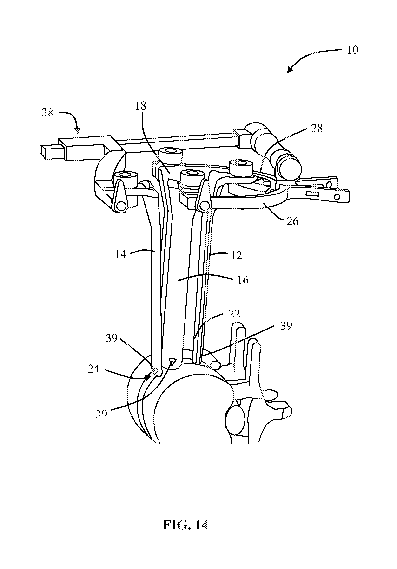
D00015
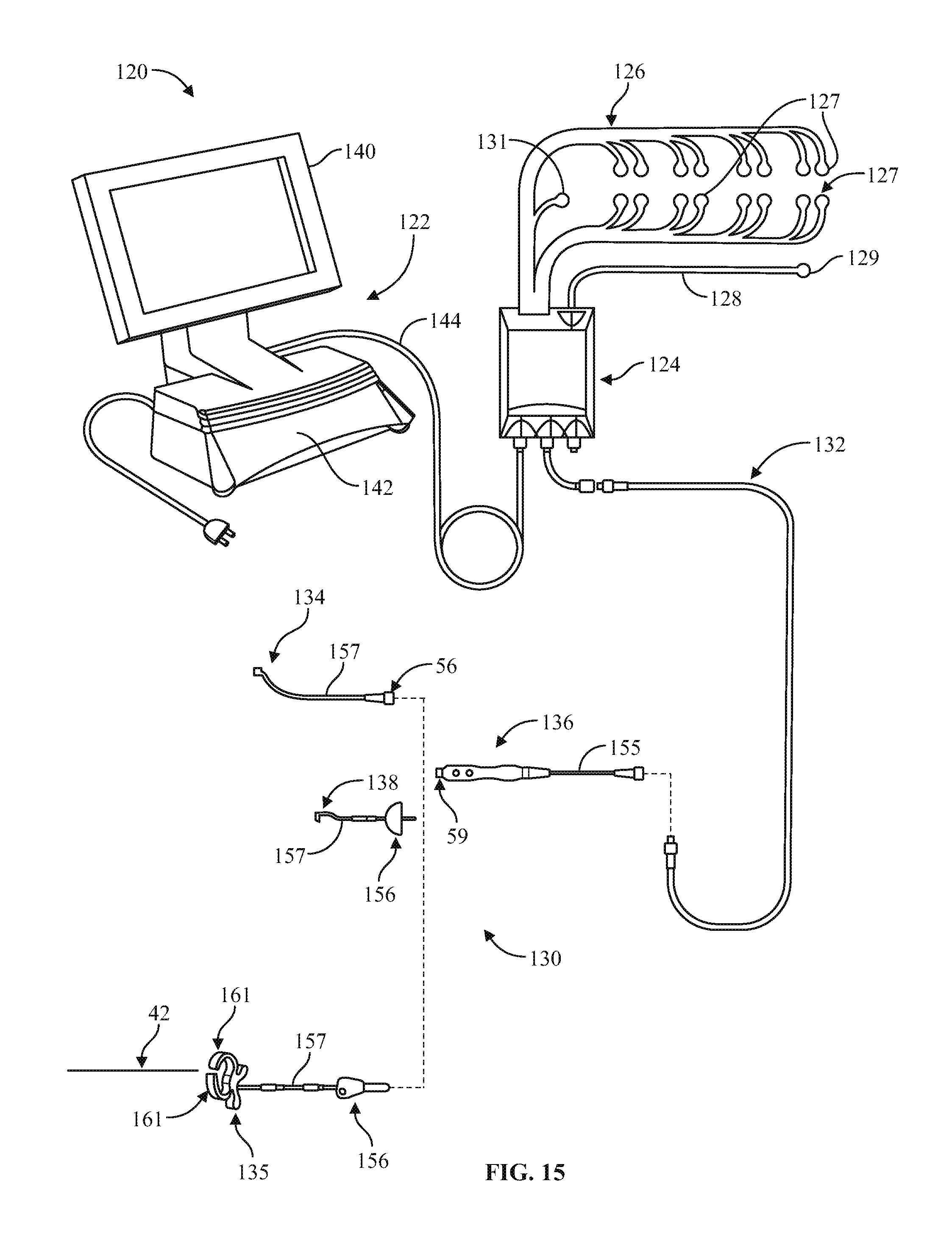
D00016

D00017

D00018

XML
uspto.report is an independent third-party trademark research tool that is not affiliated, endorsed, or sponsored by the United States Patent and Trademark Office (USPTO) or any other governmental organization. The information provided by uspto.report is based on publicly available data at the time of writing and is intended for informational purposes only.
While we strive to provide accurate and up-to-date information, we do not guarantee the accuracy, completeness, reliability, or suitability of the information displayed on this site. The use of this site is at your own risk. Any reliance you place on such information is therefore strictly at your own risk.
All official trademark data, including owner information, should be verified by visiting the official USPTO website at www.uspto.gov. This site is not intended to replace professional legal advice and should not be used as a substitute for consulting with a legal professional who is knowledgeable about trademark law.