Illumination structure for uniform illumination of keys
Cao , et al.
U.S. patent number 10,310,167 [Application Number 15/261,972] was granted by the patent office on 2019-06-04 for illumination structure for uniform illumination of keys. This patent grant is currently assigned to APPLE INC.. The grantee listed for this patent is Apple Inc.. Invention is credited to Robert Y. Cao, Mahesh Krishnamurthi, Craig C. Leong, Rong Liu, Dinesh C. Mathew, Jun Qi, Victor H. Yin, Bradford J. Zercoe.


| United States Patent | 10,310,167 |
| Cao , et al. | June 4, 2019 |
Illumination structure for uniform illumination of keys
Abstract
Described is an illumination structure for a key of a keyboard. The illumination structure is used to uniformly illuminate the key and any glyphs that are present on the key. The illumination structure includes a light guide having various features that increase total internal reflection and also illuminate the glyphs of the key.
| Inventors: | Cao; Robert Y. (Cupertino, CA), Leong; Craig C. (Cupertino, CA), Zercoe; Bradford J. (Cupertino, CA), Mathew; Dinesh C. (Cupertino, CA), Krishnamurthi; Mahesh (Cupertino, CA), Qi; Jun (Cupertino, CA), Liu; Rong (Cupertino, CA), Yin; Victor H. (Cupertino, CA) | ||||||||||
|---|---|---|---|---|---|---|---|---|---|---|---|
| Applicant: |
|
||||||||||
| Assignee: | APPLE INC. (Cupertino,
CA) |
||||||||||
| Family ID: | 58407091 | ||||||||||
| Appl. No.: | 15/261,972 | ||||||||||
| Filed: | September 11, 2016 |
Prior Publication Data
| Document Identifier | Publication Date | |
|---|---|---|
| US 20170090106 A1 | Mar 30, 2017 | |
Related U.S. Patent Documents
| Application Number | Filing Date | Patent Number | Issue Date | ||
|---|---|---|---|---|---|
| 15014596 | Feb 3, 2016 | 9971084 | |||
| 62233975 | Sep 28, 2015 | ||||
| Current U.S. Class: | 1/1 |
| Current CPC Class: | G06F 1/1662 (20130101); H01H 13/14 (20130101); G02B 6/0061 (20130101); H01H 13/023 (20130101); H01H 13/83 (20130101); G02B 6/0038 (20130101); G02B 6/0045 (20130101); H01H 13/7065 (20130101); H01H 2219/0622 (20130101); H01H 2219/06 (20130101); H01H 2219/062 (20130101); H01H 2219/056 (20130101) |
| Current International Class: | F21V 8/00 (20060101); H01H 13/7065 (20060101); H01H 13/83 (20060101); H01H 13/02 (20060101); G06F 1/16 (20060101); H01H 13/14 (20060101) |
| Field of Search: | ;362/23.03 |
References Cited [Referenced By]
U.S. Patent Documents
| 3657492 | April 1972 | Arndt et al. |
| 3917917 | November 1975 | Murata |
| 3978297 | August 1976 | Lynn et al. |
| 4095066 | June 1978 | Harris |
| 4319099 | March 1982 | Asher |
| 4349712 | September 1982 | Michalski |
| 4484042 | November 1984 | Matsui |
| 4596905 | June 1986 | Fowler |
| 4598181 | July 1986 | Selby |
| 4670084 | June 1987 | Durand et al. |
| 4755645 | July 1988 | Naoki et al. |
| 4937408 | June 1990 | Hattori et al. |
| 4987275 | January 1991 | Miller et al. |
| 5021638 | June 1991 | Nopper et al. |
| 5092459 | March 1992 | Uljanic et al. |
| 5136131 | August 1992 | Komaki |
| 5278372 | January 1994 | Takagi et al. |
| 5280146 | January 1994 | Inagaki et al. |
| 5340955 | August 1994 | Calvillo et al. |
| 5382762 | January 1995 | Mochizuki |
| 5397867 | March 1995 | Demeo |
| 5408060 | April 1995 | Muurinen |
| 5421659 | June 1995 | Liang |
| 5422447 | June 1995 | Spence |
| 5457297 | October 1995 | Chen |
| 5477430 | December 1995 | LaRose et al. |
| 5481074 | January 1996 | English |
| 5504283 | April 1996 | Kako et al. |
| 5512719 | April 1996 | Okada et al. |
| 5625532 | April 1997 | Sellers |
| 5804780 | September 1998 | Bartha |
| 5828015 | October 1998 | Coulon |
| 5847337 | December 1998 | Chen |
| 5874700 | February 1999 | Hochgesang |
| 5875013 | February 1999 | Takahara |
| 5876106 | March 1999 | Kordecki et al. |
| 5878872 | March 1999 | Tsai |
| 5881866 | March 1999 | Miyajima et al. |
| 5898147 | April 1999 | Domzaiski et al. |
| 5924555 | July 1999 | Sadamori et al. |
| 5935691 | August 1999 | Tsai |
| 5960942 | October 1999 | Thornton |
| 5986227 | November 1999 | Hon |
| 6020565 | February 2000 | Pan |
| 6068416 | May 2000 | Kumamoto et al. |
| 6215420 | April 2001 | Harrison et al. |
| 6257782 | July 2001 | Maruyama et al. |
| 6259046 | July 2001 | Iwama et al. |
| 6377685 | April 2002 | Krishnan |
| 6388219 | May 2002 | Hsu et al. |
| 6423918 | July 2002 | King et al. |
| 6482032 | November 2002 | Szu et al. |
| 6530283 | March 2003 | Okada et al. |
| 6538801 | March 2003 | Jacobson et al. |
| 6542355 | April 2003 | Huang |
| 6552287 | April 2003 | Janniere |
| 6556112 | April 2003 | Van Zeeland et al. |
| 6559399 | May 2003 | Hsu et al. |
| 6560612 | May 2003 | Yamada et al. |
| 6572289 | June 2003 | Lo et al. |
| 6573463 | June 2003 | Ono |
| 6585435 | July 2003 | Fang |
| 6624369 | September 2003 | Ito et al. |
| 6706986 | March 2004 | Hsu |
| 6738050 | May 2004 | Comiskey |
| 6750414 | June 2004 | Sullivan |
| 6759614 | July 2004 | Yoneyama |
| 6762381 | July 2004 | Kunthady et al. |
| 6765503 | July 2004 | Chan et al. |
| 6788450 | September 2004 | Kawai et al. |
| 6797906 | September 2004 | Ohashi |
| 6850227 | February 2005 | Takahashi et al. |
| 6860660 | March 2005 | Hochgesang et al. |
| 6911608 | June 2005 | Levy |
| 6926418 | August 2005 | Ostergard et al. |
| 6940030 | September 2005 | Takeda et al. |
| 6977352 | December 2005 | Oosawa |
| 6979792 | December 2005 | Lai |
| 6987466 | January 2006 | Welch et al. |
| 6987503 | January 2006 | Inoue |
| 7012206 | March 2006 | Oikawa |
| 7030330 | April 2006 | Suda |
| 7038832 | May 2006 | Kanbe |
| 7126499 | October 2006 | Lin et al. |
| 7129930 | October 2006 | Cathey et al. |
| 7134205 | November 2006 | Bruennel |
| 7146701 | December 2006 | Mahoney et al. |
| 7151236 | December 2006 | Ducruet et al. |
| 7151237 | December 2006 | Mahoney et al. |
| 7154059 | December 2006 | Chou |
| 7166813 | January 2007 | Soma |
| 7172303 | February 2007 | Shipman et al. |
| 7189932 | March 2007 | Kim |
| 7256766 | August 2007 | Albert et al. |
| 7283119 | October 2007 | Kishi |
| 7301113 | November 2007 | Nishimura et al. |
| 7312790 | December 2007 | Sato et al. |
| 7378607 | May 2008 | Koyano et al. |
| 7385806 | June 2008 | Liao |
| 7391555 | June 2008 | Albert et al. |
| 7414213 | August 2008 | Hwang |
| 7429707 | September 2008 | Yanai et al. |
| 7432460 | October 2008 | Clegg |
| 7510342 | March 2009 | Lane et al. |
| 7531764 | May 2009 | Lev et al. |
| 7541554 | June 2009 | Hou |
| 7589292 | September 2009 | Jung et al. |
| 7639187 | December 2009 | Caballero et al. |
| 7639571 | December 2009 | Ishii et al. |
| 7651231 | January 2010 | Chou et al. |
| 7679010 | March 2010 | Wingett |
| 7724415 | May 2010 | Yamaguchi |
| 7781690 | August 2010 | Ishii |
| 7813774 | October 2010 | Perez-Noguera |
| 7842895 | November 2010 | Lee |
| 7847204 | December 2010 | Tsai |
| 7851819 | December 2010 | Shi |
| 7866866 | January 2011 | Wahlstrom |
| 7893376 | February 2011 | Chen |
| 7923653 | April 2011 | Ohsumi |
| 7947915 | May 2011 | Lee et al. |
| 7999748 | August 2011 | Ligtenberg et al. |
| 8063325 | November 2011 | Sung et al. |
| 8077096 | December 2011 | Chiang et al. |
| 8080744 | December 2011 | Yeh et al. |
| 8098228 | January 2012 | Shimodaira et al. |
| 8109650 | February 2012 | Chang et al. |
| 8119945 | February 2012 | Lin |
| 8124903 | February 2012 | Tatehata et al. |
| 8134094 | March 2012 | Tsao et al. |
| 8143982 | March 2012 | Lauder et al. |
| 8156172 | April 2012 | Muehl et al. |
| 8178808 | May 2012 | Strittmatter et al. |
| 8184021 | May 2012 | Chou |
| 8212160 | July 2012 | Tsao |
| 8212162 | July 2012 | Zhou |
| 8218301 | July 2012 | Lee |
| 8232958 | July 2012 | Tolbert |
| 8246228 | August 2012 | Ko et al. |
| 8253048 | August 2012 | Ozias et al. |
| 8253052 | September 2012 | Chen |
| 8263887 | September 2012 | Chen et al. |
| 8289280 | October 2012 | Travis |
| 8299382 | October 2012 | Takemae et al. |
| 8317384 | November 2012 | Chung et al. |
| 8319298 | November 2012 | Hsu |
| 8325141 | December 2012 | Marsden |
| 8330725 | December 2012 | Mahowald et al. |
| 8354629 | January 2013 | Lin |
| 8378857 | February 2013 | Pance |
| 8383972 | February 2013 | Liu |
| 8384566 | February 2013 | Bocirnea |
| 8404990 | March 2013 | Lutgring et al. |
| 8451146 | March 2013 | Mahowald et al. |
| 8431849 | April 2013 | Chen |
| 8436265 | May 2013 | Koike et al. |
| 8462514 | June 2013 | Myers et al. |
| 8500348 | August 2013 | Dumont et al. |
| 8502094 | August 2013 | Chen |
| 8542194 | September 2013 | Akens et al. |
| 8548528 | October 2013 | Kim et al. |
| 8564544 | October 2013 | Jobs et al. |
| 8569639 | October 2013 | Strittmatter |
| 8575632 | November 2013 | Kuramoto et al. |
| 8581127 | November 2013 | Jhuang et al. |
| 8592699 | November 2013 | Kessler et al. |
| 8592702 | November 2013 | Tsai |
| 8592703 | November 2013 | Johnson et al. |
| 8604370 | December 2013 | Chao |
| 8629362 | January 2014 | Knighton et al. |
| 8642904 | February 2014 | Chiba et al. |
| 8651720 | February 2014 | Sherman et al. |
| 8659882 | February 2014 | Liang et al. |
| 8731618 | May 2014 | Jarvis et al. |
| 8748767 | June 2014 | Ozias et al. |
| 8759705 | June 2014 | Funakoshi et al. |
| 8760405 | June 2014 | Nam |
| 8786548 | July 2014 | Oh et al. |
| 8791378 | July 2014 | Lan |
| 8835784 | September 2014 | Hirota |
| 8847090 | September 2014 | Ozaki |
| 8847711 | September 2014 | Yang et al. |
| 8853580 | October 2014 | Chen |
| 8854312 | October 2014 | Meierling |
| 8870477 | October 2014 | Merminod et al. |
| 8884174 | November 2014 | Chou et al. |
| 8921473 | December 2014 | Hyman |
| 8922476 | December 2014 | Stewart et al. |
| 8943427 | January 2015 | Heo et al. |
| 8976117 | March 2015 | Krahenbuhl et al. |
| 8994641 | March 2015 | Stewart et al. |
| 9007297 | April 2015 | Stewart et al. |
| 9012795 | April 2015 | Niu et al. |
| 9024214 | May 2015 | Niu et al. |
| 9029723 | May 2015 | Pegg |
| 9063627 | June 2015 | Yairi et al. |
| 9064642 | June 2015 | Welch et al. |
| 9086733 | July 2015 | Pance |
| 9087663 | July 2015 | Los |
| 9093229 | July 2015 | Leong et al. |
| 9213416 | December 2015 | Chen |
| 9223352 | December 2015 | Smith et al. |
| 9234486 | January 2016 | Das et al. |
| 9235236 | January 2016 | Nam |
| 9274654 | March 2016 | Slobodin et al. |
| 9275810 | March 2016 | Pance et al. |
| 9300033 | March 2016 | Han et al. |
| 9305496 | April 2016 | Kimura |
| 9405369 | August 2016 | Modarres et al. |
| 9412533 | August 2016 | Hendren et al. |
| 9443672 | September 2016 | Martisauskas |
| 9448628 | September 2016 | Tan et al. |
| 9448631 | September 2016 | Winter et al. |
| 9449772 | September 2016 | Leong et al. |
| 9471185 | October 2016 | Guard |
| 9477382 | October 2016 | Hicks et al. |
| 9502193 | November 2016 | Niu et al. |
| 9612674 | April 2017 | Degner et al. |
| 9734965 | August 2017 | Martinez et al. |
| 9793066 | October 2017 | Brock et al. |
| 2002/0079211 | June 2002 | Katayama et al. |
| 2002/0093436 | July 2002 | Lien |
| 2002/0113770 | August 2002 | Jacobson et al. |
| 2002/0149835 | October 2002 | Kanbe |
| 2003/0169232 | September 2003 | Ito |
| 2004/0004559 | January 2004 | Rast |
| 2004/0225965 | November 2004 | Garside et al. |
| 2005/0035950 | February 2005 | Daniels |
| 2005/0253801 | November 2005 | Kobayashi |
| 2006/0011458 | January 2006 | Purcocks |
| 2006/0020469 | January 2006 | Rast |
| 2006/0120790 | June 2006 | Chang |
| 2006/0181511 | August 2006 | Woolley |
| 2006/0243987 | November 2006 | Lai |
| 2007/0200823 | August 2007 | Bytheway et al. |
| 2007/0285393 | December 2007 | Ishakov |
| 2008/0131184 | June 2008 | Brown et al. |
| 2008/0136782 | June 2008 | Mundt et al. |
| 2008/0251370 | October 2008 | Aoki |
| 2009/0046053 | February 2009 | Shigehiro et al. |
| 2009/0103964 | April 2009 | Takagi et al. |
| 2009/0128496 | May 2009 | Huang |
| 2009/0262085 | October 2009 | Wassingbo et al. |
| 2009/0267892 | October 2009 | Faubert |
| 2010/0045705 | February 2010 | Vertegaal et al. |
| 2010/0066568 | March 2010 | Lee |
| 2010/0109921 | May 2010 | Annerfors |
| 2010/0156796 | June 2010 | Kim et al. |
| 2010/0253630 | October 2010 | Homma et al. |
| 2011/0032127 | February 2011 | Roush |
| 2011/0048908 | March 2011 | Nishino |
| 2011/0056817 | March 2011 | Wu |
| 2011/0056836 | March 2011 | Tatebe et al. |
| 2011/0205179 | August 2011 | Braun |
| 2011/0261031 | October 2011 | Muto |
| 2011/0267272 | November 2011 | Meyer et al. |
| 2011/0284355 | November 2011 | Yang |
| 2012/0012446 | January 2012 | Hwa |
| 2012/0032972 | February 2012 | Hwang |
| 2012/0090973 | April 2012 | Liu |
| 2012/0098751 | April 2012 | Liu |
| 2012/0286701 | November 2012 | Yang et al. |
| 2012/0298496 | November 2012 | Zhang |
| 2012/0313856 | December 2012 | Hsieh |
| 2013/0043115 | February 2013 | Yang et al. |
| 2013/0093500 | April 2013 | Bruwer |
| 2013/0093733 | April 2013 | Yoshida |
| 2013/0100030 | April 2013 | Los et al. |
| 2013/0120265 | May 2013 | Horii et al. |
| 2013/0161170 | June 2013 | Fan et al. |
| 2013/0215079 | August 2013 | Johnson et al. |
| 2013/0242601 | September 2013 | Kloeppel et al. |
| 2013/0270090 | October 2013 | Lee |
| 2014/0015777 | January 2014 | Park et al. |
| 2014/0027259 | January 2014 | Kawana et al. |
| 2014/0071654 | March 2014 | Chien |
| 2014/0082490 | March 2014 | Jung et al. |
| 2014/0090967 | April 2014 | Inagaki |
| 2014/0098042 | April 2014 | Kuo et al. |
| 2014/0118264 | May 2014 | Leong et al. |
| 2014/0151211 | June 2014 | Zhang |
| 2014/0184496 | July 2014 | Gribetz et al. |
| 2014/0191973 | July 2014 | Zellers et al. |
| 2014/0218851 | August 2014 | Klein et al. |
| 2014/0252881 | September 2014 | Dinh et al. |
| 2014/0291133 | October 2014 | Fu et al. |
| 2014/0375141 | December 2014 | Nakajima |
| 2015/0016038 | January 2015 | Niu et al. |
| 2015/0083561 | March 2015 | Han et al. |
| 2015/0090570 | April 2015 | Kwan et al. |
| 2015/0090571 | April 2015 | Leong et al. |
| 2015/0270073 | September 2015 | Yarak, III et al. |
| 2015/0277559 | October 2015 | Vescovi et al. |
| 2015/0287553 | October 2015 | Welch et al. |
| 2015/0309538 | October 2015 | Zhang |
| 2015/0332874 | November 2015 | Brock et al. |
| 2015/0348726 | December 2015 | Hendren |
| 2015/0370339 | December 2015 | Ligtenberg et al. |
| 2015/0378391 | December 2015 | Huitema et al. |
| 2016/0048163 | February 2016 | Degner |
| 2016/0049266 | February 2016 | Stringer et al. |
| 2016/0093452 | March 2016 | Zercoe et al. |
| 2016/0172129 | June 2016 | Zercoe et al. |
| 2016/0189890 | June 2016 | Leong et al. |
| 2016/0189891 | June 2016 | Zercoe |
| 2016/0259375 | September 2016 | Andre et al. |
| 2016/0329166 | November 2016 | Hou et al. |
| 2016/0336124 | November 2016 | Leong et al. |
| 2016/0336127 | November 2016 | Leong et al. |
| 2016/0336128 | November 2016 | Leong et al. |
| 2016/0343523 | November 2016 | Hendren et al. |
| 2016/0351360 | December 2016 | Knopf et al. |
| 2016/0365204 | December 2016 | Cao et al. |
| 2016/0378234 | December 2016 | Ligtenberg et al. |
| 2016/0379775 | December 2016 | Leong et al. |
| 2017/0004937 | January 2017 | Leong et al. |
| 2017/0004939 | January 2017 | Kwan et al. |
| 2017/0011869 | January 2017 | Knopf et al. |
| 2017/0090106 | March 2017 | Cao et al. |
| 2017/0301487 | October 2017 | Leong et al. |
| 2017/0315624 | November 2017 | Leong et al. |
| 2018/0029339 | February 2018 | Liu et al. |
| 2018/0040441 | February 2018 | Wu et al. |
| 2018/0074694 | March 2018 | Lehmann et al. |
| 2155620 | Feb 1994 | CN | |||
| 2394309 | Aug 2000 | CN | |||
| 1533128 | Sep 2004 | CN | |||
| 1542497 | Nov 2004 | CN | |||
| 2672832 | Jan 2005 | CN | |||
| 1624842 | Jun 2005 | CN | |||
| 1812030 | Aug 2006 | CN | |||
| 1838036 | Sep 2006 | CN | |||
| 1855332 | Nov 2006 | CN | |||
| 101051569 | Oct 2007 | CN | |||
| 200961844 | Oct 2007 | CN | |||
| 200986871 | Dec 2007 | CN | |||
| 101146137 | Mar 2008 | CN | |||
| 201054315 | Apr 2008 | CN | |||
| 201084602 | Jul 2008 | CN | |||
| 201123174 | Sep 2008 | CN | |||
| 201149829 | Nov 2008 | CN | |||
| 101315841 | Dec 2008 | CN | |||
| 201210457 | Mar 2009 | CN | |||
| 101438228 | May 2009 | CN | |||
| 101465226 | Jun 2009 | CN | |||
| 101494130 | Jul 2009 | CN | |||
| 101502082 | Aug 2009 | CN | |||
| 201298481 | Aug 2009 | CN | |||
| 101546667 | Sep 2009 | CN | |||
| 101572195 | Nov 2009 | CN | |||
| 101800281 | Aug 2010 | CN | |||
| 101807482 | Aug 2010 | CN | |||
| 101868773 | Oct 2010 | CN | |||
| 201655616 | Nov 2010 | CN | |||
| 102110542 | Jun 2011 | CN | |||
| 102119430 | Jul 2011 | CN | |||
| 201904256 | Jul 2011 | CN | |||
| 102163084 | Aug 2011 | CN | |||
| 201927524 | Aug 2011 | CN | |||
| 201945951 | Aug 2011 | CN | |||
| 201945952 | Aug 2011 | CN | |||
| 201956238 | Aug 2011 | CN | |||
| 102197452 | Sep 2011 | CN | |||
| 202008941 | Oct 2011 | CN | |||
| 202040690 | Nov 2011 | CN | |||
| 102280292 | Dec 2011 | CN | |||
| 102338348 | Feb 2012 | CN | |||
| 102375550 | Mar 2012 | CN | |||
| 202205161 | Apr 2012 | CN | |||
| 102496509 | Jun 2012 | CN | |||
| 10269527 | Aug 2012 | CN | |||
| 102622089 | Aug 2012 | CN | |||
| 102629526 | Aug 2012 | CN | |||
| 202372927 | Aug 2012 | CN | |||
| 102679239 | Sep 2012 | CN | |||
| 102683072 | Sep 2012 | CN | |||
| 202434387 | Sep 2012 | CN | |||
| 202523007 | Nov 2012 | CN | |||
| 102832068 | Dec 2012 | CN | |||
| 102955573 | Mar 2013 | CN | |||
| 102956386 | Mar 2013 | CN | |||
| 102969183 | Mar 2013 | CN | |||
| 103000417 | Mar 2013 | CN | |||
| 103165327 | Jun 2013 | CN | |||
| 103180979 | Jun 2013 | CN | |||
| 203012648 | Jun 2013 | CN | |||
| 203135988 | Aug 2013 | CN | |||
| 103377841 | Oct 2013 | CN | |||
| 103489986 | Jan 2014 | CN | |||
| 203414880 | Jan 2014 | CN | |||
| 103681056 | Mar 2014 | CN | |||
| 103699181 | Apr 2014 | CN | |||
| 203520312 | Apr 2014 | CN | |||
| 203588895 | May 2014 | CN | |||
| 103839715 | Jun 2014 | CN | |||
| 103839720 | Jun 2014 | CN | |||
| 103839722 | Jun 2014 | CN | |||
| 103903891 | Jul 2014 | CN | |||
| 103956290 | Jul 2014 | CN | |||
| 203733685 | Jul 2014 | CN | |||
| 104021968 | Sep 2014 | CN | |||
| 204102769 | Jan 2015 | CN | |||
| 204117915 | Jan 2015 | CN | |||
| 104517769 | Apr 2015 | CN | |||
| 204632641 | Sep 2015 | CN | |||
| 105097341 | Nov 2015 | CN | |||
| 2530176 | Jan 1977 | DE | |||
| 3002772 | Jul 1981 | DE | |||
| 29704100 | Apr 1997 | DE | |||
| 202008001970 | Aug 2008 | DE | |||
| 0441993 | Aug 1991 | EP | |||
| 1835272 | Sep 2007 | EP | |||
| 1928008 | Jun 2008 | EP | |||
| 2202606 | Jun 2010 | EP | |||
| 2426688 | Mar 2012 | EP | |||
| 2439760 | Apr 2012 | EP | |||
| 2463798 | Jun 2012 | EP | |||
| 2664979 | Nov 2013 | EP | |||
| 2147420 | Mar 1973 | FR | |||
| 2911000 | Jul 2008 | FR | |||
| 2950193 | Mar 2011 | FR | |||
| 1361459 | Jul 1974 | GB | |||
| S50115562 | Sep 1975 | JP | |||
| S60055477 | Mar 1985 | JP | |||
| S61172422 | Oct 1986 | JP | |||
| S62072429 | Apr 1987 | JP | |||
| S63182024 | Nov 1988 | JP | |||
| H0422024 | Apr 1992 | JP | |||
| H0520963 | Jan 1993 | JP | |||
| H0524512 | Aug 1993 | JP | |||
| H05342944 | Dec 1993 | JP | |||
| H09204148 | Aug 1997 | JP | |||
| H10312726 | Nov 1998 | JP | |||
| H11194882 | Jul 1999 | JP | |||
| 2000010709 | Jan 2000 | JP | |||
| 2000057871 | Feb 2000 | JP | |||
| 2000339097 | Dec 2000 | JP | |||
| 2001100889 | Apr 2001 | JP | |||
| 2003114751 | Sep 2001 | JP | |||
| 2002260478 | Sep 2002 | JP | |||
| 2002298689 | Oct 2002 | JP | |||
| 2003522998 | Jul 2003 | JP | |||
| 2005031412 | Feb 2005 | JP | |||
| 2005108041 | Apr 2005 | JP | |||
| 2006164929 | Jun 2006 | JP | |||
| 2006185906 | Jul 2006 | JP | |||
| 2006521664 | Sep 2006 | JP | |||
| 2006269439 | Oct 2006 | JP | |||
| 2006277013 | Oct 2006 | JP | |||
| 2006344609 | Dec 2006 | JP | |||
| 2007115633 | May 2007 | JP | |||
| 2007514247 | May 2007 | JP | |||
| 2007156983 | Jun 2007 | JP | |||
| 2008021428 | Jan 2008 | JP | |||
| 2008041431 | Feb 2008 | JP | |||
| 2008100129 | May 2008 | JP | |||
| 2008191850 | Aug 2008 | JP | |||
| 2008533559 | Aug 2008 | JP | |||
| 2008293922 | Dec 2008 | JP | |||
| 2009099503 | May 2009 | JP | |||
| 2009181894 | Aug 2009 | JP | |||
| 2010061956 | Mar 2010 | JP | |||
| 2010244088 | Oct 2010 | JP | |||
| 2010244302 | Oct 2010 | JP | |||
| 3167038 | Jan 2011 | JP | |||
| 2011018484 | Jan 2011 | JP | |||
| 2011049092 | Mar 2011 | JP | |||
| 2011065126 | Mar 2011 | JP | |||
| 2011150804 | Aug 2011 | JP | |||
| 2011165630 | Aug 2011 | JP | |||
| 2011524066 | Aug 2011 | JP | |||
| 2011187297 | Sep 2011 | JP | |||
| 2012022473 | Feb 2012 | JP | |||
| 2012043705 | Mar 2012 | JP | |||
| 2012063630 | Mar 2012 | JP | |||
| 2012098873 | May 2012 | JP | |||
| 2012134064 | Jul 2012 | JP | |||
| 2012186067 | Sep 2012 | JP | |||
| 2012230256 | Nov 2012 | JP | |||
| 2014017179 | Jan 2014 | JP | |||
| 2014026807 | Feb 2014 | JP | |||
| 2014216190 | Nov 2014 | JP | |||
| 2014220039 | Nov 2014 | JP | |||
| 2016053778 | Apr 2016 | JP | |||
| 1019990007394 | Jan 1999 | KR | |||
| 1020020001668 | Jan 2002 | KR | |||
| 100454203 | Oct 2004 | KR | |||
| 1020060083032 | Jul 2006 | KR | |||
| 1020080064116 | Jul 2008 | KR | |||
| 1020080066164 | Jul 2008 | KR | |||
| 2020110006385 | Jun 2011 | KR | |||
| 1020120062797 | Jun 2012 | KR | |||
| 1020130040131 | Apr 2013 | KR | |||
| 20150024201 | Mar 2015 | KR | |||
| V201108284 | Mar 2011 | TV | |||
| 200703396 | Jan 2007 | TW | |||
| M334397 | Jun 2008 | TW | |||
| 201108286 | Mar 2011 | TW | |||
| M407429 | Jul 2011 | TW | |||
| 201246251 | Nov 2012 | TW | |||
| 201403646 | Jan 2014 | TW | |||
| WO9744946 | Nov 1997 | WO | |||
| WO2005/057320 | Jun 2005 | WO | |||
| WO2006/022313 | Mar 2006 | WO | |||
| WO2007/049253 | May 2007 | WO | |||
| WO2008/045833 | Apr 2008 | WO | |||
| WO2009/005026 | Jan 2009 | WO | |||
| WO2012/011282 | Jan 2012 | WO | |||
| WO2012/027978 | Mar 2012 | WO | |||
| WO2013/096478 | Jun 2013 | WO | |||
| WO2014175446 | Oct 2014 | WO | |||
Other References
|
Elekson, "Reliable and Tested Wearable Electronics Embedment Solutions," http://www.wearable.technology/our-technologies, 3 pages, at least as early as Jan. 6, 2016. cited by applicant . U.S. Appl. No. 14/472,260, filed Aug. 28, 2014, pending. cited by applicant . U.S. Appl. No. 14/501,680, filed Sep. 30, 2014, pending. cited by applicant . U.S. Appl. No. 15/014,596, filed Feb. 3, 2016, pending. cited by applicant . U.S. Appl. No. 15/230,724, filed Aug. 8, 2016, pending. cited by applicant . U.S. Appl. No. 15/342,715, filed Nov. 3, 2016, pending. cited by applicant. |
Primary Examiner: Bowman; Mary Ellen
Attorney, Agent or Firm: Dorsey & Whitney LLP
Parent Case Text
CROSS-REFERENCE TO RELATED APPLICATIONS
This application is a continuation patent application of U.S. patent application Ser. No. 15/014,596, filed Feb. 3, 2016 and titled "Illumination Structure for Uniform Illumination of Keys," which is a nonprovisional patent application of and claims the benefit of U.S. Provisional Patent Application No. 62/233,975, filed Sep. 28, 2015 and titled "Illumination Structure for Uniform Illumination of Keys," the disclosures of which are hereby incorporated herein by reference in their entireties.
Claims
What is claimed is:
1. A keyboard comprising: a keyboard base; and a set of keys coupled to the keyboard base, one of the keys of the set of keys comprising: a switch body formed at least partially from a light transmissive material and comprising: an opening in a central region of the switch body configured to receive at least part of a dome switch; and an attachment feature positioned along a side of the switch body; a hinge mechanism coupled to the switch body via the attachment feature; a keycap coupled to the hinge mechanism; and a light source configured to couple light to the keycap via the switch body.
2. The keyboard of claim 1, wherein: the switch body further comprises a recess; and the light source is positioned at least partially in the recess.
3. The keyboard of claim 1, wherein the hinge mechanism comprises: a first wing; a second wing opposite the first wing; and a living hinge coupling the first wing to the second wing.
4. The keyboard of claim 3, wherein: the first and second wings each comprise a pivot member; and the pivot members interlock with the attachment feature to retain the hinge mechanism to the switch body.
5. The keyboard of claim 1, wherein the light transmissive material is a transparent plastic.
6. The keyboard of claim 1, wherein the switch body further comprises a lens configured to direct light out of the switch body.
7. The keyboard of claim 1, wherein: the keycap comprises a glyph; and the light source is configured to couple the light to the glyph.
8. A key for a keyboard, comprising: a light emitting element; a keycap; a light transmissive body configured to receive light from the light emitting element and direct the light towards the keycap; a keycap support mechanism movably coupling the keycap to the light transmissive body; and a collapsible dome within an opening in the light transmissive body.
9. The key of claim 8, wherein a top surface of the collapsible dome is substantially flush with a top surface of the light transmissive body.
10. The key of claim 9, wherein the collapsible dome is a metal dome.
11. The key of claim 10, wherein the collapsible dome provides tactile feedback to the keycap when the keycap is actuated.
12. The key of claim 8, wherein: the light transmissive body comprises an attachment feature; and the keycap support mechanism is pivotally coupled to the light transmissive body via the attachment feature.
13. The key of claim 12, wherein the keycap is pivotally coupled to the keycap support mechanism.
14. The key of claim 8, wherein the light emitting element emits light into the light transmissive body through a side surface of the light transmissive body.
15. A switch body for a key of a keyboard, comprising: a body formed from a light transmissive material and defining: a top surface; a bottom surface opposite the top surface; an opening extending completely through the body from the top surface to the bottom surface and configured to receive a collapsible dome therein; and a recess along a side of the body and configured to receive a light source therein; wherein the body is configured to direct light from the light source out of the top surface of the body.
16. The switch body of claim 15, further comprising an attachment feature formed in the side of the body and configured to couple to a pivot member of a keycap support mechanism.
17. The switch body of claim 16, wherein the attachment feature is a recess.
18. The switch body of claim 17, wherein the recess is dimensioned to allow the pivot member to slide within the recess.
19. The switch body of claim 15, wherein the light transmissive material is a translucent plastic.
20. The switch body of claim 15, wherein the opening is substantially circular.
Description
FIELD
Embodiments described herein are directed to input devices for computing systems. More particularly the described embodiments are directed to illumination structures that facilitate substantially uniform illumination of select features of such input devices.
BACKGROUND
Electronic devices can receive user input from a keyboard. The keys of the keyboard may be illuminable and thus visible to a user in dimly-lit environments. A key can be illuminated in a number of ways. For example, a light-emitting diode ("LED") can be disposed behind a keycap of an illuminable key to direct light toward and through a translucent portion of the keycap. In many cases, the location, orientation, and size of such an LED is limited by the structure of the key itself, which, in turn, affects the quality, uniformity, and quantity of light visible to a user.
SUMMARY
Embodiments described herein disclose a keyboard including a group of keys. At least one key of the group of keys includes a compressible dome, a keycap positioned above the compressible dome, a light emitting element, and a light guide positioned at least partially around the compressible dome. The light guide is optically coupled to the light emitting element and includes a light-directing feature operative to direct light from the light emitting element around the light guide, a set of reflection features operative to reflect the light internally around the light guide and a set of illumination features operative to illuminate the keycap.
Also disclosed is an illumination structure for a key of a keyboard. The illumination structure includes a light emitting element, a structural body, and a light guide coupled to the structural body. The light guide includes a set of reflection features operative to reflect the light internally around the light guide. A density of the reflection features may increase from a first location to a second location. The light guide also includes a set of illumination features operative to illuminate at least a portion of a keycap positioned above the illumination structure.
The present disclosure also describes a key for a keyboard. The key includes a keycap disposed within an aperture defined by the keyboard, a compressible dome positioned below the keycap, a key mechanism positioned around the compressible dome and coupled to the keycap and a structural body positioned beneath the key mechanism and formed from an optically translucent material. The structural body is coupled to the key mechanism. The key also includes a light emitting element and a light guide optically coupled to the light emitting element. The light guide includes a first internal feature that is operative to increase an amount of light that is internally reflected (e.g., within the light guide), a second internal feature that is operative to illuminate a hollow interior portion of the structural body, and a third internal feature that is operative to illuminate at least a portion of the keycap.
BRIEF DESCRIPTION OF THE DRAWINGS
Reference will now be made to representative embodiments illustrated in the accompanying figures. It should be understood that the following descriptions are not intended to limit the embodiments to one preferred embodiment. To the contrary, it is intended to cover alternatives, modifications, and equivalents as may be included within the spirit and scope of the described embodiments as defined by the appended claims.
FIG. 1A depicts an electronic device incorporating a keyboard with illuminable keys;
FIG. 1B is an expanded view of the region A-A of FIG. 1A;
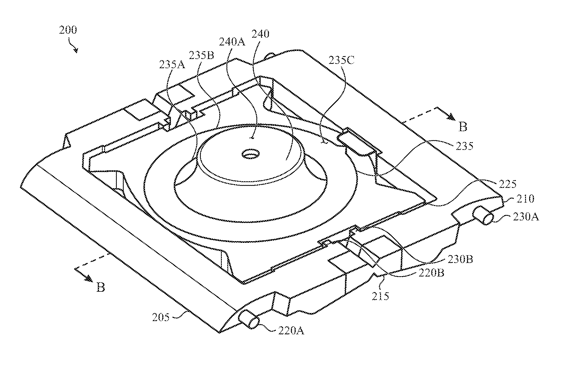
FIG. 2A depicts an example key mechanism that may be used with an illuminable key of the keyboard shown in FIGS. 1A-1B;
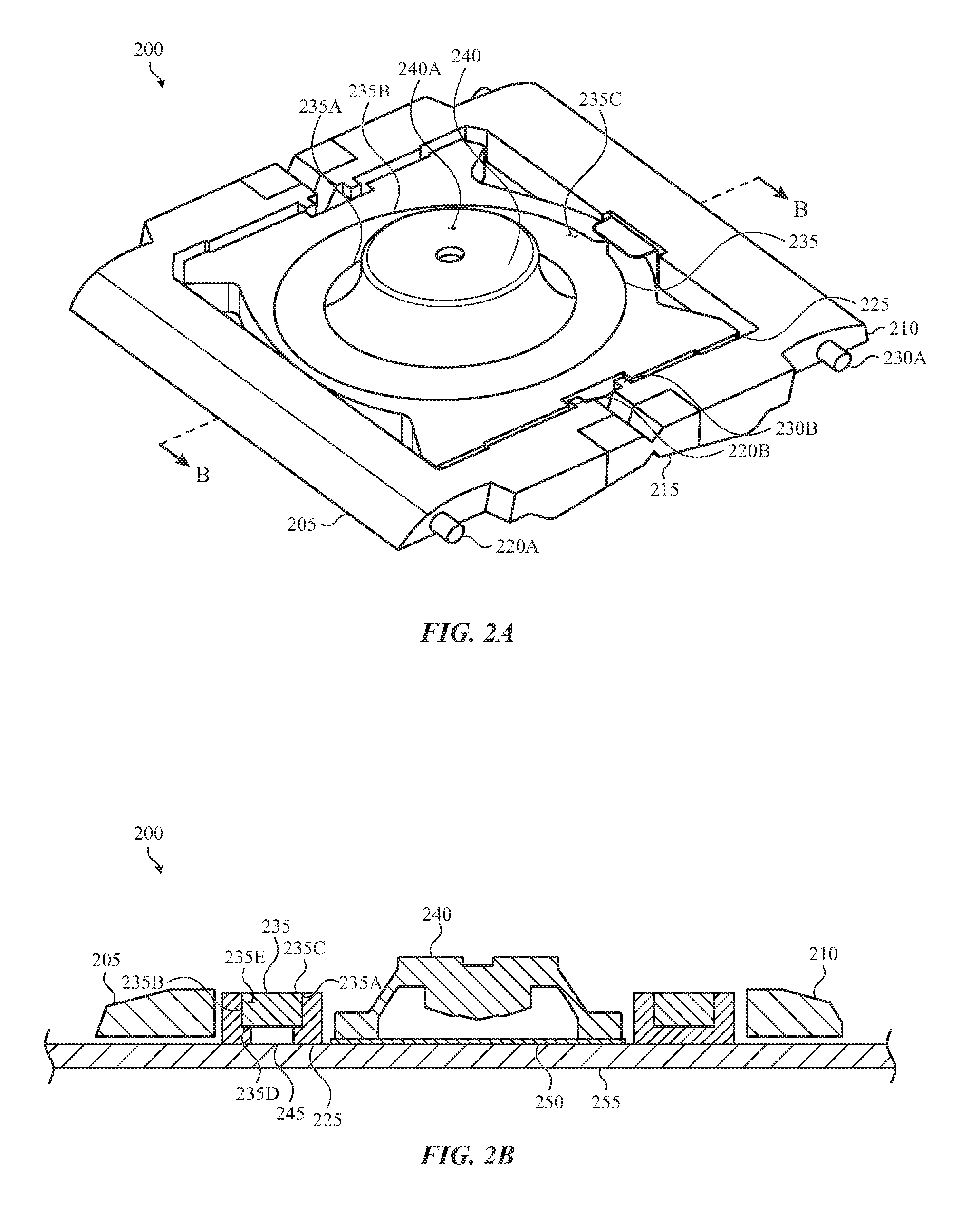
FIG. 2B depicts a cross-section view of the key mechanism of FIG. 2A taken along line B-B of FIG. 2A;
FIG. 3 illustrates an example illumination structure having a first configuration;
FIG. 4 illustrates an example illumination structure having a second configuration;
FIG. 5 illustrates an example illumination structure having a third configuration;
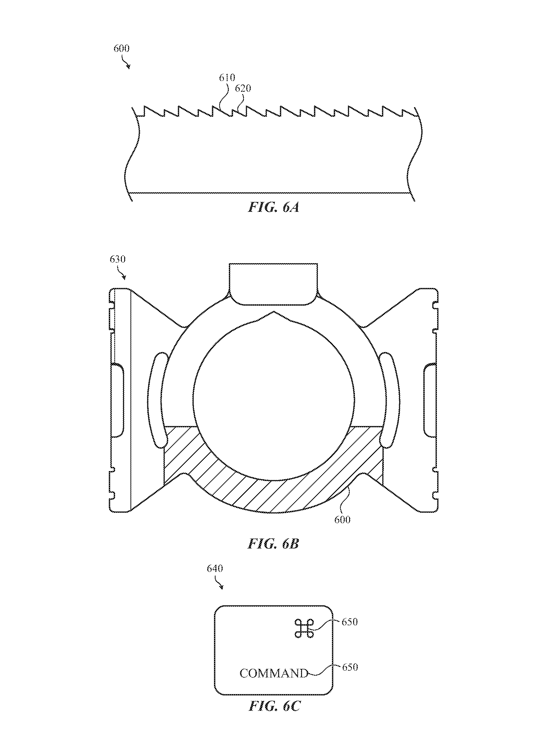
FIG. 6A illustrates various internal features that may be used in an example illumination structure;
FIG. 6B illustrates an example placement of the internal features of FIG. 6A on an illumination structure; and
FIG. 6C illustrates an example keycap for a key that may be illuminated using the illumination structure of FIG. 6B.
The use of the same or similar reference numerals in different figures indicates similar, related, or identical items.
The use of cross-hatching or shading in the accompanying figures is generally provided to clarify the boundaries between adjacent elements and also to facilitate legibility of the figures. Accordingly, neither the presence nor the absence of cross-hatching or shading conveys or indicates any preference or requirement for particular materials, material properties, element proportions, element dimensions, commonalities of similarly illustrated elements, or any other characteristic, attribute, or property for any element illustrated in the accompanying figures.
DETAILED DESCRIPTION
Reference will now be made in detail to representative embodiments illustrated in the accompanying drawings. It should be understood that the following descriptions are not intended to limit the embodiments to one preferred embodiment. To the contrary, it is intended to cover alternatives, modifications, and equivalents as can be included within the spirit and scope of the described embodiments as defined by the appended claims.
Embodiments described herein are directed to illumination structures that illuminate one or more keys of a keyboard. An illumination structure may include a light emitting element, such as a light-emitting diode, that is optically coupled to a light guide. The light guide may be positioned below the key to convey light from the light emitting element to an illuminable portion of the key.
As used herein, the phrase "illuminable portion of a key" refers generally to any or all areas of (or adjacent to) a keycap or other input surface of a key that is intended to be illuminated by the light guide such that the location, size, and/or functionality of the key, or a portion of the key, is visually emphasized.
For example, a key may include a glyph that defines an alphanumeric character, a symbol, a word, a phrase, an abbreviation, or any other linguistic, scientific, numeric, or pictographic symbol or set of symbols. The glyph can be formed in, on, or beneath an outer surface of a key and is typically translucent or transparent. In one example, the glyph is illuminated upon activation of the light emitting element. In other examples, other portions of the key associated with the glyph are illuminated upon activation of the light emitting element. Examples include a glyph border, a glyph underline, a glyph outline, and so on.
The geometry of the key may also be an illuminable portion of a key. In one example, the light emitting element illuminates a perimeter of the key. In other examples, other portions of the key are illuminated. These portions may include an external surface of the key, a sidewall of the key, a corner of the key, and so on.
In further examples, the light emitting element can illuminate spaces between one or more keys and the adjacent structure of a keyboard. For example, an aperture in which a key is disposed illuminates upon activation of the light emitting element, thereby generating a halo around a base of the key.
As noted above, the light emitting element is optically coupled to a light guide. In some embodiments, the light guide takes the shape of a ring. In some implementations, the ring can be symmetrical about an axis. In other implementations, the ring can be asymmetrical. Although a ring shape is specifically mentioned, other shapes are contemplated.
The light guide may be formed from an optically translucent (or transparent) material. A body of the light guide can define an inner sidewall, an outer sidewall, a top surface, and a bottom surface. The light emitting element is optically coupled, either directly or indirectly, to a body of the light guide. The surfaces are optically coupled, either directly or indirectly, to the illuminable portions of the key.
In some implementations, the light guide includes various internal features. As used herein, the phrase "internal feature" means a feature that is contained within, or formed on, a body or structure of the light guide that causes light to be internally reflected through the light guide and may also cause the light to illuminate portions of the key. Although internal features are specifically defined as being contained within the body or structure of the light guide, similar features may be provided on an outer surface or structure of the light guide. Using the various internal features described, greater internal reflection may be realized while still providing substantially uniform illumination to the key.
In one example, the light guide includes a light-directing feature that directs light from the light emitting element into a first direction of travel and a second direction of travel. The light guide also includes a set of reflection features that reflect light internally (e.g., into the interior of the light guide). The light guide also includes a set of illumination features that are operative to direct light out of a top surface of the light guide to illuminate the key. One or more sidewalls of the light guide may also include various prisms, serrations, scallops or other such shapes that reflect light into a center portion of the light guide to illuminate a dome switch. Using these various structures, light emitted by the light emitting element travels through the light guide and exits the light guide in a greater quantity and in a more uniform manner. In other embodiments, a light guide, or portions of the light guide, can form a structural portion of the key in addition to directing light.
The light guide also includes one or more internal reflectors such as rectilinear through-holes, laser etched or routed channels, insert-molded reflectors, or the like. The internal reflectors are positioned and oriented to direct light (via internal reflection) within the structural body and/or the light guide. In some cases, the internal reflectors are oriented oblique to a light emitting element. The internal reflectors direct light around structural features of the body that can cause light to undesirably scatter, leak, or exit the body away from the illuminable portion of the key ("light leakage"). In this manner, light emitted by the light emitting element exits the light guide in a greater quantity and in a more uniform manner through the top surface and/or the various sidewalls and thus to the illuminable portion of the key, because less light is lost to leakage.
These and other embodiments are discussed below with reference to FIGS. 1A-6C. However, those skilled in the art will readily appreciate that the detailed description given herein with respect to these Figures is for explanatory purposes only and should not be construed as limiting.
FIG. 1A depicts an electronic device 100 incorporating a keyboard with illuminable keys, such as the illuminable key 110 depicted in a removed view of greater scale identified by the enclosed circle A-A, shown in FIGS. 1A-1B.
The electronic device 100 is a portable laptop computer including an integrated keyboard with illuminable keys, such as an illuminable key 110. The illuminable key 110 at least partially extends through an aperture 120 defined in a housing 130 of the electronic device 100. The illuminable key 110 depresses at least partially into the aperture 120 when a user presses the illuminable key 110. In one example, a top surface of the illuminable key 110 is flush with a top surface of the housing 130 of the electronic device 100 when the illuminable key 110 is fully pressed.
A structure associated with the illuminable key 110 is disposed at least partially within the aperture 120. This structure, referred to as a "key stack," can include a keycap, a key mechanism, an elastomeric dome, a switch housing, and electronic switch circuitry. The keycap typically defines at least one illuminable portion, depicted in FIG. 1A as a glyph 140. The glyph 140 can be an alphanumeric character, a symbol, a word, a phrase, an abbreviation, or any other linguistic, scientific, numeric, or pictographic symbol or set of symbols. Further, the glyph 140 can be positioned at various locations on the key 110. In addition, a single key 110 may include a single glyph 140 or multiple glyphs 140.
FIG. 2A depicts an example key mechanism 200 that may be used with an illuminable key of the keyboard shown in FIGS. 1A-1B. The key mechanism 200 is depicted in a depressed configuration (e.g., the key is pressed by a user).
The key mechanism 200 may have a first wing 205 and a second wing 210 that are coupled together with a hinge 215. The first wing 205 and the second wing 210 are substantially symmetric across the hinge 215. For example, the first wing 205 and the second wing 210 may be formed in a U-shape such as shown although this is not required. The free ends of the first wing 205 and the second wing 210 may be coupled by the hinge 215 to form a closed ring.
In many cases, the hinge 215 is a living hinge formed from a flexible material such as a polymer or elastomer. In other cases, the hinge 215 is a flexible member overmolded onto the first wing 205 and the second wing 210. The flexible member can be formed from metal, fabric, a polymer, or the like. In other embodiments, the first wing 205 and the second wing 210 can be formed from an optically translucent or transparent material and can be optically coupled to a light emitting element. In this manner, the first wing 205 and the second wing 210 can serve as a portion of a light guide.
Although a single hinge 215 in shown, the key mechanism 200 may include multiple hinges. For example, as shown in FIG. 2A, the first wing 205 and the second wing 210 are joined by two hinges 215 that are positioned opposite each other.
The first wing 205 and the second wing 210 are typically formed from the same material, although this is not required. For example, in one embodiment, the first wing 205 is formed from a plastic material doped with glass fibers and the second wing 210 is formed from metal. In other embodiments, both the first wing 205 and the second wing 210 are formed from a doped plastic material. In one embodiment, the doped plastic material can be selected to increase the strength and/or rigidity of the first wing 205 and the second wing 210.
Both the first wing 205 and the second wing 210 include geometry configured to interlock with one or more other structural portions of the key mechanism 200. For example, the first wing 205 may include a keycap pivot 220A (or other interlocking feature) that interlocks with and/or slides within a portion of a keycap (not shown) positioned above the key mechanism 200. The first wing 205 also includes a structural pivot 220B (or other interlocking feature) that interlocks with and/or slides within a portion of a structural body 225 of the key mechanism 200. Similarly, the second wing 210 includes a keycap pivot 230A that interlocks with and/or slides within a portion of the keycap. The second wing 210 also includes a structural pivot 230B that interlocks with and/or slides within a portion of the structural body 225.
The structural body 225 is formed from a rigid material such as plastic or metal. As with the first wing 205 and the second wing 210, the structural body 225 can be formed from a doped material. The structural body 225 can also be formed from an optically transparent or translucent material although this is not required. In one example, the structural body 225 can be formed from an optically opaque material. In other examples, the structural body 225 can be formed from a translucent material that takes a particular color.
A light guide 235 is positioned on or within the structural body 225. The light guide 235 may be shaped as a ring although such a configuration is not required. For example, the light guide 235 can take a square shape, a rectangular shape, a grid shape, an asymmetrical shape or any other shape or combination of shapes. In still further examples, the light guide 235 may be formed as a segmented shape, such as a segmented ring.
The light guide 235 is formed from an optically translucent or transparent material such as acrylic, glass, or plastic. In many examples, the light guide 235 is insert-molded into the structural body 225. In other embodiments, the light guide 235 is co-molded with the structural body 225. In still further examples, the light guide 235 is molded into a light guide cavity that is defined within the structural body 225. In another implementation, the light guide 235 may be formed as a separate piece and may be joined or otherwise coupled to the structural body 225.
The light guide 235 includes a body that defines an inner sidewall 235A, an outer sidewall 235B, a top surface 235C, and a bottom surface (not visible in FIG. 2A). In some embodiments, one or both of the inner sidewall 235A and the outer sidewall 235B may include one or more internal features that direct and/or reflect light. The top surface 235C and/or the bottom surface may also include one or more internal features that direct and/or reflect light.
For example, one or both of the inner sidewall 235A and the outer sidewall 235B may include a set of reflection features that reflect light internally around the light guide 235. The inner sidewall 235A may also include a set of features that illuminate a compressible dome 240 positioned in a center of the key mechanism 200.
One or more of the top surface 235C and the bottom surface may also include a set of illumination features that illuminate a keycap or portions of the keycap. For example, a bottom surface of the light guide 235 may have one or more internal features that reflect light into a glyph on a keycap. Although the above features are described as being internal features, one or more of these features may be provided on an outer surface of the light guide 235.
In some embodiments, and as a result of the features described above, each of the inner sidewall 235A and the outer sidewall 235B of the light guide 235 may exhibit greater internal reflection than the top surface 235C and the bottom surface of the light guide 235. In this manner, light emitted into the light guide 235 by a light emitting element will exit the light guide 235 in a greater quantity and in a more uniform manner through the top surface 235C than through any other portion of the light guide 235. In some examples, the top surface 235C is optically diffusive.
The light guide 235 is optically coupled, either directly or indirectly, to one or more illuminable portions of the key. In one example, the light guide 235 is optically coupled to the glyph 140 of the illuminable key 110 depicted in FIGS. 1A-1B. With respect to the orientation shown in FIG. 1B, the light guide 235 reflects light toward the bottom left hand portion of the illuminable key 110. For example, in place of a ring configuration such as depicted in FIG. 2A, the top surface 235C of the light guide 235 can take a circular shape, positioned in the leftmost corner of the structural body 225 so that the top surface 235C is positioned substantially below the glyph 140 of the illuminable key 110 depicted in FIGS. 1A-1B. For other glyphs 140 taking other shapes, the light guide 235 can take a different shape. In this manner, the shape and size of the light guide 235 is selected based on the geometry of the illuminable portion to which the light guide 235 is optically coupled.
In another embodiment, the light guide 235, or one or more surfaces of the light guide 235, may include one or more internal features that direct light to the illuminable portion of the illuminable key 110. For example, one or more surfaces of the light guide 235 may include various cut-out features that direct light to the illuminable portion such as, for example, the glyph 140. In such embodiments, the cut-out feature may be offset from the illuminable portion. In another embodiment, the cut-out feature may be below the illuminable portion. In still yet other embodiments, the cut-out feature may be integrated with or otherwise be formed with the other internal features of the light guide 235 described above.
The light guide 235 may be disposed around a through-hole, an aperture or other hollow interior portion defined by the structural body 225. The through-hole may be circular, rounded, curved although this is not required and the through-hole can take other shapes.
The key mechanism 200 may also include a compressible dome 240. The compressible dome 240 is disposed within the through-hole. In some embodiments, the compressible dome 240 is formed from an elastomeric material although other materials may be used. The compressible dome 240 may be formed from a transparent or translucent material. For example, the compressible dome 240 is formed from an optically opaque material. In other examples, the compressible dome 240 is formed from an optically translucent material of a particular color (e.g., white). In this way, the compressible dome 240, or portions of the compressible dome 240, may be illuminated by the internal features of the light guide 235.
In some embodiments, the compressible dome 240 extends a certain distance above a top surface of the structural body 225. In other embodiments, the compressible dome 240 is flush with a top surface of the structural body 225.
In many embodiments, a top surface 240A the compressible dome 240 interfaces with the underside of the keycap (not shown) of the illuminable key. In one example, the underside of the keycap includes a projection that contacts the top surface 240A of the compressible dome 240. In other cases, the underside of the keycap can include an indentation that receives the top surface 240A of the compressible dome 240. The compressible dome 240 collapses into the through-hole to activate electronic switch circuitry associated with the illuminable key in response to a user pressing the keycap. In embodiments wherein the internal features of the light guide 235 illuminate the compressible dome 240, light from the light guide may illuminate the top surface 240A of the compressible dome 240 as well as one or more glyphs on the keycap.
As discussed above, the key mechanism 200 is depicted in FIGS. 2A-2B in a depressed configuration (e.g., when the key is pressed by a user). As such, the first wing 205 and the second wing 210 are fully extended. When the key mechanism 200 is in its nominal state, the outermost portions of the first wing 205 and the second wing 210 extend above the structural body 225. The first wing 205 and the second wing 210 also pivot relative to one another and relative to the structural body 225 at the hinge 215.
FIG. 2B depicts a cross-section view of the key mechanism of FIG. 2A taken along line B-B of FIG. 2A. As depicted in FIG. 2A, the first wing 205 and the second wing 210, when coupled by the hinge(s), define an internal area in which the structural body 225 is positioned. The light guide 235 is disposed within a portion of the structural body 225. As illustrated, the top surface 235C of the light guide 235 is substantially flush with a top surface of the structural body 225, although such a configuration is not required. For example, in some embodiments, the top surface 235C extends proud of a top surface of the structural body 225. In other examples, the top surface 235C is inset into the structural body 225.
In some embodiments, the light guide 235 extends partially, but not entirely, through the structural body 225. More particularly, a bottom surface 235D of the light guide 235 mates with an internal portion of the structural body 225. In other embodiments, the bottom surface 235D can extend through the entire depth of the structural body 225.
Although the bottom surface 235D is illustrated as substantially parallel to the top surface 235C, such a configuration is not required. For example, the bottom surface 235D can be oblique to the top surface 235C.
As noted above, the light guide 235 can include a body 235E. The body 235E is optically coupled, either directly or indirectly, to a light emitting element 245. The body 235E may be optically coupled to the light emitting element 245 through the bottom surface 235D of the light guide 235. In other embodiments, the light emitting element 245 can be optically coupled to the light guide 235 at a different location. In other examples, the light emitting element 245 can be optically coupled to the light guide 235 indirectly, such as via a light pipe.
The light emitting element 245 includes one or more light-emitting diodes. The light-emitting diodes emit light of a particular color and at a particular brightness. In some embodiments, the light emitting element 245 provides light of a variable color or a variable brightness. In one example, the light emitting element 245 emits white light having a cool color temperature, although this is not required.
An electrical switch layer 250 is also depicted in FIG. 2B. The electrical switch layer 250 is disposed below the compressible dome 240 such that an electrical property of the electrical switch layer 250 changes when the compressible dome 240 compresses or contacts the electrical switch layer 250. In one example, the compressible dome 240 completes an electrical contact between electrical traces or contacts disposed on the electrical switch layer 250 when the compressible dome 240 is compressed. The electrical traces may be organized in an interleaved comb pattern or a concentric circular pattern. In other embodiments, the compressible dome 240 can cause a change in a capacitance measured between one or more portions of the electrical switch layer 250.
In some implementations, the key mechanism 200 is disposed on a substrate 255. The substrate 255 can be positioned within a housing of an electronic device, such as the electronic device 100 depicted in FIGS. 1A-1B. In other embodiments, the substrate 255 can be positioned within an aperture defined by the housing of an electronic device 100. In one example, the substrate 255 is formed from a rigid material such as metal or plastic.
As noted with respect to other embodiments described herein, the inner sidewall 235A and the outer sidewall 235B of the light guide 235 exhibit greater internal reflection than the top surface 235C and the bottom surface 235D. More particularly, the internal reflection of light vectored toward a sidewall of the light guide 235 may be greater than the internal reflection of light vectored toward a surface of the light guide. For example, the sidewalls of the light guide 235 may be more optically reflective than the top and bottom surfaces of the light guide 235.
As may be appreciated, the reflectivity of a surface may depend upon the angle of incidence with which light strikes the surface and the difference between the refractive indices of the materials interfacing at the surface. More specifically, at the boundary between the light guide 235 and another material (e.g., air, the structural body 225, the keycap, and so on) having a lower refractive index than that of the light guide 235, light within the light guide 235 may be reflected internally. If the angle of incidence of the light is sufficiently high, total internal reflection may occur (e.g., almost zero light passes through the boundary and effectively all light reflects back into the body 235E). Thus, in some cases, the inner sidewall 235A and the outer sidewall 235B can exhibit total internal reflection. In some embodiments, the bottom surface 235D may also exhibit greater internal reflection than the top surface 235C.
For these embodiments, most of the light emitted into the light guide 235 by the light emitting element 245 will either reflect off the inner sidewall 235A and/or the outer sidewall 235B (and/or the bottom surface 235D), or will exit the light guide 235 through the top surface 235C. However, and as will be discussed below, the inner sidewall 235A may include various internal features that enable the light to illuminate the dome 240.
As discussed above, internal reflection of light can cause light to be reflected or emitted in a substantially uniform manner across the entire surface of the top surface 235C. More specifically, the portion of the top surface 235C that is diametrically opposite the light emitting element 245 (e.g., the point that is farthest away from the light emitting element 245) can emit a quantity of light substantially similar to the other portions of the top surface 235C. In this manner, the light guide 235 facilitates substantially uniform emission of light from its body 235E.
As a result, the illuminable portions of the key to which the light guide 235 is optically coupled (either directly or indirectly) are illuminated in a substantially uniform manner.
FIG. 3 illustrates an example illumination structure 300 having a first configuration. The illumination structure 300 may be used as part of a key mechanism such as, for example key mechanism 200 shown and described above with respect to FIGS. 2A-2B.
The illumination structure 300 may have a structural body 305 and a light guide 310 such as described above. For example, the light guide 310 may be rounded, curved or have any other shape. The structural body 305 may have or otherwise define a hollow interior portion. The light guide 310 may be adjacent to or otherwise surround the hollow interior portion.
The light guide 310 may include one or more internal features 315. The internal features 315 may be positioned on a bottom surface of the light guide 310, a top surface of the light guide 310, an inner side wall of the light guide 310 and/or and outer sidewall of the light guide 310. More specifically, the light guide 310 may include a number of different internal features 315. Further, different internal features may be positioned on different surfaces of the light guide 310.
For example, a first type of internal feature may be a reflection feature that causes light to be reflected internally around the light guide 310. More specifically, the first type of internal feature may be one or more lenticular structures. The lenticular structures may include dome shaped features, lens shaped features and other such structures that may be used to pull or otherwise reflect light around the light guide 310. The lenticular structures may be positioned on a bottom surface of the light guide 310, a top surface of the light guide and/or one or more sidewalls of the light guide 310.
The lenticular structures, as well as other internal features described herein, may be arranged in a number of different orientations and patterns. In addition, a density of the lenticular structures may increase from a first portion of the light guide 310 to a second portion of the light guide 310. For example, and as shown by the shading in FIG. 3 (and as also shown by the shading in FIGS. 4-5) the density of the lenticular structures may be less near a light emitting element 335 and gradually become greater the farther away the structures are from the light emitting element 335. In other implementations, the density of the lenticular structures may be greater near the light emitting element 335 and less the farther away from the light emitting element 335. In yet another implementation, the density of the lenticular structures may remain constant or substantially constant.
As light travels around the light guide 310, some of the light may be lost to light leakage. In addition, some of the light may be extracted by other internal features and used to illuminate portions of the key such as will be described in more detail below. Accordingly, increasing the density of the some of the internal features, such as the lenticular structures, helps compensate for the light that is lost which helps provide more uniform illumination. For example, as the absolute amount of light within the light guide 310 decreases, the high density internal features extract a greater percentage of available light thereby providing more uniform illumination around the light guide 310.
The light guide 310 may also include a second type of internal feature 315. Like the first type of internal feature 315, the density of the second type of internal feature 315 may increase, decrease or stay substantially the same as the distance from the light emitting element 335 increases.
The second type of internal feature 315 may be a sidewall feature that allows light to escape the light guide 310 and illuminate the hollow interior portion of the structural body 305. The sidewall feature may also illuminate a dome 340 that is positioned within the hollow interior portion. In some embodiments, the sidewall feature may be disposed on an inner sidewall of the light guide 310 and/or an outer sidewall of the light guide 310 although this is not required. In addition, the sidewall feature may be provided on an external sidewall of the light guide 310.
The second type of internal feature 315 may consist of a repeating pattern of prisms. In some embodiments, the prisms may be triangular or may have a sawtooth (e.g., serrated) shape although other shapes are contemplated.
The dimensions of each of the prisms may vary. In addition, and as with the other internal features described herein, a geometry of the prisms disposed on the sidewalls can be determined or approximated, at least in part, based on the refractive index of the material selected for the light guide.
The light guide 310 may also include a third type of internal feature 315 that is operative to illuminate a keycap positioned above the illumination structure 300. For example, the third type of internal feature 315 may be an illumination feature or a light extraction feature that is operative to illuminate the keycap, one or more glyphs on the keycap, a border surrounding or adjacent the keycap and the like.
For example, the illumination feature may be operative to direct light through the top surface of the light guide 310 and into the keycap. More specifically, the illumination feature causes light from the light emitting element 335 to exit the top surface of the light guide 310 and illuminate the keycap.
In some implementations, a density of the illumination features may change depending on the position of the illumination features with respect to the light emitting element 335. In addition, the illumination feature may be interspersed with the other internal features described above. For example, the light guide 310 or one or more surfaces of the light guide 310 may have a set of internal reflection features interspersed with the illumination features. In other implementations, the light guide 310 may be made of or otherwise include a number of different layers. In such cases, each layer may have one or more of the various internal features 315 described above.
The light guide 310 may also include a light-directing feature 330 and a light emitting element 335. The light guide 310 may be optically coupled, either directly or indirectly, to the light emitting element 335. The light emitting element 335 is positioned to emit light into the light guide 310. In some cases, the light emitting element 335 may emit light directly into a sidewall (e.g., outer sidewall) of the light guide 310. In other embodiments, the light emitting element 335 is coupled to a bottom surface of the light guide 310. In still other embodiments, the light emitting element 335 is optically coupled to both the top and bottom surfaces of the light guide 310. Regardless of where the light emitting element 335 is positioned, one or more light-directing feature 330 can be formed within the structural body 305 to direct light emitted from the light emitting element 335 in a particular direction.
In some embodiments, the light-directing feature 330 may be positioned within the light guide 310 and/or on an outer surface of the light guide 310 near or otherwise adjacent the light emitting element 335. The light-directing feature 330 directs light from the light emitting element 335 down one or more paths of the light guide 310.
For example, in this particular embodiment, the light-directing feature 330 may reflect light down the right side of the light guide 310 and the left side of the light guide 310 in order to increase the uniformity of light throughout the light guide 310. The light-directing feature 330 may include one or more structures that may be used to reflect or direct light. In one non-limiting example, the light-directing feature 330 includes one or more Fresnel lenses. Although Fresnel lenses are specifically mentioned, other lenses and/or light-directing surfaces may be used. For example, in some embodiments, the light-directing feature 330 can be implemented as a chamfer formed in the inner sidewall of the light guide 310. In other embodiments, the light-directing feature 330 is a non-flat surface such as a convex surface, a concave surface, or a domed surface. In some other non-limiting examples, the light-directing feature 330 can also be coated with a reflective coating or material such as a metalized ink.
The light-directing feature 330 may have a number of different orientations. For example, the light-directing feature 330 may be angled toward a top surface of the light guide 310. In another embodiment, the light-directing feature may be angled toward one or more sidewalls of the light guide 310. The angle of the light-directing feature 330 can be selected, at least in part, to increase or maximize the internal reflection of light emitting from the light emitting element 335.
The structural body 305 may also include a number of ribs 345 that extend from the light guide 310. The ribs 345 are placed at locations around the light guide 310 and are used to increase the amount of light that is internally reflected. For example, the ribs 345 may be placed at certain areas around the light guide 310 that are more permeable to light than other areas. In some embodiments, the ribs 345 are placed at locations in the light guide 310 with a low density of internal features 315.
The ribs 345 are coupled to or are otherwise formed with an attachment mechanism 320. The attachment mechanism 320 may be used to couple a structural pivot of a hinge (e.g., structural pivot 220B and structural pivot 230B) to the illumination structure 300. In this arrangement, the illumination structure 300 may have a bowtie configuration. Although a bowtie configuration is specifically mentioned, other configurations are contemplated and described in more detail below.
The illumination structure 300 also includes one or more reflective features 325. The reflective features 325 may be implemented as a through-hole, a laser etched or routed channel, an insert molded reflector, or the like. The reflective features 325 may be positioned adjacent to the light guide 310 and oriented to direct light (via internal reflection) within the body of the light guide 310. More specifically, the reflective features 325 may be implemented as apertures (filled or open) through the body of the light guide 310. In this manner, the reflective features 325 introduce a refractive index mismatch between the material of the body of the light guide 310 and air within the aperture, thereby increasing the quantity of light within the body of the light guide 310 that is subject to internal reflection and decrease the quantity of light within the body of the light guide 310 that is subject to transmission into the reflective feature 325. Accordingly, as the light hits the reflective features 325, the refractive index of the reflective features 325 causes light to be reflected into the light guide 310. Although two reflective features 325 are shown, the illumination structure 300 may include any number of reflective features 325 positioned at various locations around the light guide 310.
FIG. 4 illustrates an example illumination structure 400 having a second configuration. The illumination structure 400 may be used as part of a key mechanism such as, for example, key mechanism 200 shown and described above with respect to FIGS. 2A-2B.
Like the illumination structure 300 described above with respect to FIG. 3, the illumination structure 400 includes a structural body 405, a light guide 410 and one or more internal feature 415. Each of the structural body 405, the light guide 410 and the internal features may be similar to those described above with respect to FIG. 3. For example, the light guide 410 may be rounded or otherwise curved, may surround, be adjacent to or otherwise define a hollow interior portion and may have various internal features 415. The internal features 415 act to reflect light internally, illuminate a keycap positioned above the illumination structure 400 and reflect light into or otherwise illuminate the hollow interior portion and/or a dome (not shown) positioned in the center of the illumination structure 400. Further, a density of the internal features 415 may increase from a first area in the light guide 410 (e.g. near the light emitting element 430) to a second area in the light guide 410 and as illustrated by the shading shown in FIG. 4.
However, unlike the light guide 310 described with respect to FIG. 3, the light guide 410 is shaped as a helix. More specifically, a first side of the light guide 410 is optically coupled to a light emitting element 430. The light emitting element 430 is oriented to emit light through the light guide 410 from the first side to a second side. For example, a set of internal features 415 within the light guide 410 operate to reflect light internally and illuminate portions of a keycap and/or a dome such as described above.
In addition, the illumination structure 400 may include a light-directing feature 435 operative to direct light through the first path. Because the light guide 410 is shaped as a helix and the light emitting element 430 emits light into a first path of the light guide, the light-directing feature 435 may not need to direct as much light down two different paths of a light guide and, as a result, may be smaller when compared to the light-directing feature 330 described above.
The illumination structure 400 also includes one or more ribs 440 that are coupled to the light guide 410. The ribs 440 act to increase the amount of light that is internally reflected such as described above. The ribs 440 are also coupled to one or more attachment mechanisms 420 that interact with a hinge of a key mechanism. The structural body 405 may also include one or more reflective features 425. The reflective features 425 may be adjacent the light guide 410 and act in a similar manner as the reflective features 325 described above.
Although the structural body 405 is shown in FIG. 4 as having a generally rectangular shape, this shape is not required. For example, the structural body 405 may be in any shape including a circular shape, a square shape, a bowtie shape and so on.
FIG. 5 illustrates an example illumination structure 500 having a third configuration. The illumination structure 500 may be used as part of a key mechanism such as, for example, key mechanism 200 shown and described above with respect to FIGS. 2A-2B.
Like the previously described illumination structures, the illumination structure 500 includes a structural body 505, a light guide 510 and one or more internal features 515. The light guide 510 may be adjacent to or otherwise define a hollow interior portion. Each of these components operates in similar manner such as described above.
The illumination structure 500 also includes a light emitting element 530 and a light-directing feature 535. However, in this implementation, the light emitting element 530 and the light-directing feature 535 are positioned in a corner of the structural body 505. Although the light emitting element 530 and the light-directing feature 535 are positioned in a corner of the structural body 505, each of these components function in a similar manner as the light emitting element 335 and light-directing feature 330 described above with respect to FIG. 3.
The illumination structure 500 also includes one or more attachment mechanisms 520 that interact with a hinge of a key mechanism. The structural body 505 may also include one or more reflective features 525. The reflective features 525 may be adjacent the light guide 510 and act to increase the amount of light that is internally reflected such as described above.
Although the structural body 505 is shown in FIG. 5 as having a generally rectangular shape, this shape is not required. For example, the structural body 505 may have any cross-sectional shape, including a circular shape, a parallelepiped shape, a bowtie shape and so on.
FIG. 6A illustrates various internal features 600 that may be used in an example illumination structure such as, for example, the various illumination structures described above with respect to FIGS. 3-5.
The internal features 600 may include one or more prisms such as, for example, a first prism 610 and a second prism 620. In some embodiments, the dimensions of the first prism 610 and the second prism 620 may vary. In other embodiments, the number of each of the prisms 610 and 620 may vary. In still yet other embodiments, the shape of the first prism 610 and the second prism 620 may also vary. For example, the first prism 610 may be rounded or scalloped while the second prism 620 has a triangular shape, a concave portion, and so on.
Due to the varying dimensions of the first prism 610 and the second prism 620, each prism may be operative to interact with light in a different manner. For example, the first prism 610 may be used to direct light in a first direction while the second prism 620 may be used to direct light in a second direction.
More specifically, the first prism 610 may be used to direct light to one more glyphs on a keycap while the second prism 620 may be used to reflect light internally through a light guide. In some implementations, the internal feature 600 may be placed on specific areas of a light guide. For example and as shown in FIG. 6B, the internal features 600 may be placed on a particular portion and/or a surface of an illumination structure 630. More specifically, one or more internal features 600 may be locally patterned on a surface of the illumination structure 630 based on, for example, the placement of glyphs on a keycap.
For example and turning to FIG. 6C, a keycap 640 may have one or more glyphs 650 placed on different areas. In such implementations, the internal features described above with respect to FIGS. 3-5 may not uniformly illuminate these glyphs 650 as they are not centered on the keycap 640. As such, and as shown in FIG. 6B, one or more internal features 600 may be provided on various parts of the illumination structure 630 in order to better illuminate these glyphs.
In one particular implementation, the internal features 600 may be offset from the glyph 650 of the keycap. For example, the glyph 650 may be positioned at a first location on the keycap while the internal features 600 are positioned on an illumination structure 630 at a position that is offset (e.g., not directly below) the glyph 650. Although the positions of the glyph 650 and the internal features 600 may be offset with respect to one another, the shape, dimensions and/or orientation of one or more of the internal features 600 direct light to the glyph 650 to illuminate it.
Although the internal features 600 are shown on a particular portion of the illumination structure 630, the internal features 600 may be placed on multiple different portions or locations on the illumination structure 630. Thus, an illumination structure 630 may be customized based on the type of glyphs and the location of glyphs on a keycap associated with the illumination structure 630.
Although many embodiments described and depicted herein reference light guides for illuminable keys of a keyboard, it should be appreciated that other implementations can take other form factors. Thus, the various embodiments described herein, as well as functionality, operation, components, and capabilities thereof may be combined with other elements as necessary, and so any physical, functional, or operational discussion of any element or feature is not intended to be limited solely to a particular embodiment to the exclusion of others.
For example, although the electronic device 100 is shown in FIGS. 1A-1B as a laptop computer, it may be appreciated that other electronic devices are contemplated. For example, the electronic device 100 can be implemented as a peripheral input device, a desktop computing device, a handheld input device, a tablet computing device, a cellular phone, a wearable device, and so on.
Further, it may be appreciated that the electronic device 100 can include one or more components that interface or interoperate, either directly or indirectly, with the illuminable key 110 which, for simplicity of illustration are not depicted in FIGS. 1A-1B. For example, the electronic device 100 may include a processor coupled to or in communication with a memory, a power supply, one or more sensors, one or more communication interfaces, and one or more input/output devices such as a display, a speaker, a rotary input device, a microphone, an on/off button, a mute button, a biometric sensor, a camera, a force and/or touch sensitive trackpad, and so on.
In some embodiments, the communication interfaces provide electronic communications between the electronic device 100 and an external communication network, device or platform. The communication interfaces can be implemented as wireless interfaces, Bluetooth interfaces, universal serial bus interfaces, Wi-Fi interfaces, TCP/IP interfaces, network communications interfaces, or any conventional communication interfaces. The electronic device 100 may provide information related to externally connected or communicating devices and/or software executing on such devices, messages, video, operating commands, and so forth (and may receive any of the foregoing from an external device), in addition to communications. As noted above, for simplicity of illustration, the electronic device 100 is depicted in FIGS. 1A-1B without many of these elements, each of which may be included, partially, optionally, or entirely, within a housing 130.
In some embodiments, the housing 130 can be configured to, at least partially, surround a display. In many examples, the display may incorporate an input device configured to receive touch input, force input, and the like and/or may be configured to output information to a user. The display can be implemented with any suitable technology, including, but not limited to, a multi-touch or multi-force sensing touchscreen that uses liquid crystal display (LCD) technology, light-emitting diode (LED) technology, organic light-emitting display (OLED) technology, organic electroluminescence (OEL) technology, or another type of display technology. In other implementations, the light source, such as, for example, light emitting element 335, may be used as a backlight for a display.
The housing 130 can form an outer surface or partial outer surface and protective case for the internal components of the electronic device 100. In the illustrated embodiment, the housing 130 is formed in a substantially rectangular shape, although this configuration is not required. The housing 130 can be formed of one or more components operably connected together, such as a front piece and a back piece or a top clamshell and a bottom clamshell. Alternatively, the housing 130 can be formed of a single piece (e.g., uniform body or unibody).
Various embodiments described herein can be incorporated with other systems or apparatuses and may not, in all cases, be directly associated with an input device configured for use with an electronic device such as depicted in FIGS. 1A-1B. For example, a light guide as described herein can be incorporated into an independent electronic switch such as a button (e.g., light switch, automotive button, doorbell, and so on). In other examples, a light guide as described herein can be incorporated into a different portion of an electronic device, such as a display element of an electronic device. In such an example, a light guide incorporating prismatic or scalloped sidewalls can be used as a backlight diffuser within a display stack.
Additionally, it may be appreciated, that for illuminable key embodiments, the various structures and mechanisms described herein are not intended to limit the disclosure to a particular favored or required geometry or form factor. For example, an illuminable key can include a butterfly mechanism, a scissor mechanism, or any other suitable type of key mechanism.
An illuminable key can include a keycap that is formed to have a substantially flat top surface or, in other embodiments, to have a partially curved top surface. An electronic switch associated with the illuminable key can be implemented as a single throw switch, a multi-throw switch, a capacitive switch, and so on. A tactile feedback structure associated with the illuminable key can be implemented as an elastomeric dome, a spring, an elastomer deposit, a metal dome, or any combination thereof.
Although the disclosure above is described in terms of various exemplary embodiments and implementations, it should be understood that the various features, aspects and functionality described in one or more of the individual embodiments are not limited in their applicability to the particular embodiment with which they are described, but instead can be applied, alone or in various combinations, to one or more of the some embodiments of the invention, whether or not such embodiments are described and whether or not such features are presented as being a part of a described embodiment. Thus, the breadth and scope of the present invention should not be limited by any of the above-described exemplary embodiments but is instead defined by the claims herein presented.
* * * * *
References
D00000
D00001
D00002
D00003
D00004
D00005
D00006
XML
uspto.report is an independent third-party trademark research tool that is not affiliated, endorsed, or sponsored by the United States Patent and Trademark Office (USPTO) or any other governmental organization. The information provided by uspto.report is based on publicly available data at the time of writing and is intended for informational purposes only.
While we strive to provide accurate and up-to-date information, we do not guarantee the accuracy, completeness, reliability, or suitability of the information displayed on this site. The use of this site is at your own risk. Any reliance you place on such information is therefore strictly at your own risk.
All official trademark data, including owner information, should be verified by visiting the official USPTO website at www.uspto.gov. This site is not intended to replace professional legal advice and should not be used as a substitute for consulting with a legal professional who is knowledgeable about trademark law.