Coordinated engine and emissions control system
Stewart , et al.
U.S. patent number 10,309,281 [Application Number 15/491,799] was granted by the patent office on 2019-06-04 for coordinated engine and emissions control system. This patent grant is currently assigned to Garrett Transportation I Inc.. The grantee listed for this patent is Honeywell spol, s.r.o.. Invention is credited to Daniel Pachner, Jaroslav Pekar, Gregory Stewart.

| United States Patent | 10,309,281 |
| Stewart , et al. | June 4, 2019 |
Coordinated engine and emissions control system
Abstract
A system for reducing environmentally harmful emissions from an internal combustion engine. The system may incorporate an exhaust after-treatment device. The exhaust after-treatment device may use selective catalytic reduction to remove certain emissions from the exhaust of the engine. Urea solution may be inserted into the exhaust emissions, which is decomposed to ammonia to become a reduction agent for reduction of NOx in the emissions. The engine may be managed by a controller and the exhaust after-treatment device may be managed by another controller. These controllers may be cascaded, or be managed by a third controller that provides hierarchical or coordinated control of engine performance and emissions reduction. The engine and the exhaust after-treatment device may be modeled to aid in designing and building a system for coordinated control of an actual engine and a selective catalytic reduction after-treatment device. The controllers may be predictive model controllers.
| Inventors: | Stewart; Gregory (North Vancouver, CN), Pekar; Jaroslav (Pacov, CZ), Pachner; Daniel (Prague, CZ) | ||||||||||
|---|---|---|---|---|---|---|---|---|---|---|---|
| Applicant: |
|
||||||||||
| Assignee: | Garrett Transportation I Inc.
(Torrance, CA) |
||||||||||
| Family ID: | 47080192 | ||||||||||
| Appl. No.: | 15/491,799 | ||||||||||
| Filed: | April 19, 2017 |
Prior Publication Data
| Document Identifier | Publication Date | |
|---|---|---|
| US 20170218815 A1 | Aug 3, 2017 | |
Related U.S. Patent Documents
| Application Number | Filing Date | Patent Number | Issue Date | ||
|---|---|---|---|---|---|
| 13236217 | Sep 19, 2011 | 9677493 | |||
| Current U.S. Class: | 1/1 |
| Current CPC Class: | F02D 41/0235 (20130101); F01N 3/208 (20130101); F01N 9/005 (20130101); F02D 41/1401 (20130101); F02D 41/266 (20130101); F01N 2900/04 (20130101); F01N 2900/1402 (20130101); Y02T 10/24 (20130101); F02D 2041/1412 (20130101); Y02T 10/12 (20130101); Y02T 10/40 (20130101); F02D 2250/36 (20130101); F01N 2610/02 (20130101); Y02T 10/47 (20130101); F02D 2041/1433 (20130101) |
| Current International Class: | F01N 3/20 (20060101); F02D 41/02 (20060101); F01N 9/00 (20060101); F02D 41/14 (20060101); F02D 41/26 (20060101) |
| Field of Search: | ;60/286,301,303 |
References Cited [Referenced By]
U.S. Patent Documents
| 3744461 | July 1973 | Davis |
| 4005578 | February 1977 | McInerney |
| 4055158 | October 1977 | Marsee |
| 4206606 | June 1980 | Yamada |
| 4252098 | February 1981 | Tomczak et al. |
| 4359991 | November 1982 | Stumpp et al. |
| 4383441 | May 1983 | Willis et al. |
| 4426982 | January 1984 | Lehner et al. |
| 4438497 | March 1984 | Willis et al. |
| 4440140 | April 1984 | Kawagoe et al. |
| 4456883 | June 1984 | Bullis et al. |
| 4485794 | December 1984 | Kimberley et al. |
| 4601270 | July 1986 | Kimberley et al. |
| 4616308 | October 1986 | Morshedi et al. |
| 4653449 | March 1987 | Kamei et al. |
| 4671235 | June 1987 | Hosaka |
| 4677559 | June 1987 | Van Bruck |
| 4735181 | April 1988 | Kaneko et al. |
| 4947334 | August 1990 | Massey et al. |
| 4962570 | October 1990 | Hosaka et al. |
| 5044337 | September 1991 | Williams |
| 5076237 | December 1991 | Hartman et al. |
| 5089236 | February 1992 | Clerc |
| 5094213 | March 1992 | Dudek et al. |
| 5095874 | March 1992 | Schnaibel et al. |
| 5108716 | April 1992 | Nishizawa |
| 5123397 | June 1992 | Richeson |
| 5150289 | September 1992 | Badavas |
| 5186081 | February 1993 | Richardson et al. |
| 5233829 | August 1993 | Komatsu |
| 5270935 | December 1993 | Dudek et al. |
| 5273019 | December 1993 | Matthews et al. |
| 5282449 | February 1994 | Takahashi et al. |
| 5293553 | March 1994 | Dudek et al. |
| 5349816 | September 1994 | Sanbayashi et al. |
| 5365734 | November 1994 | Takeshima |
| 5394322 | February 1995 | Hansen |
| 5394331 | February 1995 | Dudek et al. |
| 5398502 | March 1995 | Watanabe |
| 5408406 | April 1995 | Mathur et al. |
| 5431139 | July 1995 | Grutter et al. |
| 5452576 | September 1995 | Hamburg et al. |
| 5477840 | December 1995 | Neumann |
| 5560208 | October 1996 | Halimi et al. |
| 5570574 | November 1996 | Yamashita et al. |
| 5598825 | February 1997 | Neumann |
| 5609139 | March 1997 | Ueda et al. |
| 5611198 | March 1997 | Lane et al. |
| 5682317 | October 1997 | Keeler et al. |
| 5690086 | November 1997 | Kawano et al. |
| 5692478 | December 1997 | Nogi et al. |
| 5697339 | December 1997 | Esposito |
| 5704011 | December 1997 | Hansen et al. |
| 5740033 | April 1998 | Wassick et al. |
| 5746183 | May 1998 | Parke et al. |
| 5765533 | June 1998 | Nakajima |
| 5771867 | June 1998 | Amstutz et al. |
| 5785030 | July 1998 | Paas |
| 5788004 | August 1998 | Friedmann et al. |
| 5842340 | December 1998 | Bush et al. |
| 5846157 | December 1998 | Reinke et al. |
| 5893092 | April 1999 | Driscoll |
| 5924280 | July 1999 | Tarabulski |
| 5942195 | August 1999 | Lecea et al. |
| 5964199 | October 1999 | Atago et al. |
| 5970075 | October 1999 | Wasada |
| 5974788 | November 1999 | Hepburn et al. |
| 5995895 | November 1999 | Watt et al. |
| 6029626 | February 2000 | Bruestle |
| 6035640 | March 2000 | Kolmanovsky et al. |
| 6048620 | April 2000 | Zhong |
| 6048628 | April 2000 | Hillmann et al. |
| 6055810 | May 2000 | Borland et al. |
| 6056781 | May 2000 | Wassick et al. |
| 6058700 | May 2000 | Yamashita et al. |
| 6067800 | May 2000 | Kolmanovsky et al. |
| 6076353 | June 2000 | Fruedenberg et al. |
| 6105365 | August 2000 | Deeba et al. |
| 6122555 | September 2000 | Lu |
| 6134883 | October 2000 | Kato et al. |
| 6153159 | November 2000 | Engeler et al. |
| 6161528 | December 2000 | Akao et al. |
| 6170259 | January 2001 | Boegner et al. |
| 6171556 | January 2001 | Burk et al. |
| 6178349 | January 2001 | Kolmanovsky et al. |
| 6178743 | January 2001 | Hirota et al. |
| 6208914 | March 2001 | Ward et al. |
| 6216083 | April 2001 | Ulyanov et al. |
| 6233922 | May 2001 | Maloney |
| 6236956 | May 2001 | Mantooth et al. |
| 6237330 | May 2001 | Takahashi et al. |
| 6242873 | June 2001 | Drozdz et al. |
| 6263672 | July 2001 | Roby et al. |
| 6273060 | August 2001 | Cullen |
| 6279551 | August 2001 | Iwano et al. |
| 6312538 | November 2001 | Latypov et al. |
| 6314324 | November 2001 | Kakuyama et al. |
| 6321538 | November 2001 | Hasler |
| 6327361 | December 2001 | Harshavardhana et al. |
| 6338245 | January 2002 | Shimoda et al. |
| 6341487 | January 2002 | Takahashi et al. |
| 6347619 | February 2002 | Whiting et al. |
| 6360159 | March 2002 | Miller et al. |
| 6360541 | March 2002 | Waszkiewicz et al. |
| 6360732 | March 2002 | Bailey et al. |
| 6363715 | April 2002 | Bidner et al. |
| 6363907 | April 2002 | Arai et al. |
| 6379281 | April 2002 | Collins et al. |
| 6389803 | May 2002 | Surnilla et al. |
| 6425371 | July 2002 | Majima |
| 6427436 | August 2002 | Allansson et al. |
| 6431160 | August 2002 | Sugiyama et al. |
| 6445963 | September 2002 | Blevins et al. |
| 6446430 | September 2002 | Roth et al. |
| 6453308 | September 2002 | Zhao et al. |
| 6463733 | October 2002 | Asik et al. |
| 6463734 | October 2002 | Tamura et al. |
| 6466893 | October 2002 | Latwesen et al. |
| 6470682 | October 2002 | Gray, Jr. |
| 6470862 | October 2002 | Isobe et al. |
| 6470886 | October 2002 | Jestrabek-Hart |
| 6481139 | November 2002 | Weldle |
| 6494038 | December 2002 | Kobayashi et al. |
| 6502391 | January 2003 | Hirota et al. |
| 6505465 | January 2003 | Kanazawa et al. |
| 6510351 | January 2003 | Blevins et al. |
| 6512974 | January 2003 | Houston et al. |
| 6513495 | February 2003 | Franke et al. |
| 6532433 | March 2003 | Bharadwaj et al. |
| 6546329 | April 2003 | Bellinger |
| 6550307 | April 2003 | Zhang et al. |
| 6553754 | April 2003 | Meyer et al. |
| 6560528 | May 2003 | Gitlin et al. |
| 6560960 | May 2003 | Nishimura et al. |
| 6571191 | May 2003 | York et al. |
| 6579206 | June 2003 | Liu et al. |
| 6591605 | July 2003 | Lewis |
| 6594990 | July 2003 | Kuenstler et al. |
| 6601387 | August 2003 | Zurawski et al. |
| 6612293 | September 2003 | Schweinzer et al. |
| 6615584 | September 2003 | Ostertag |
| 6625978 | September 2003 | Eriksson et al. |
| 6629408 | October 2003 | Murakami et al. |
| 6637382 | October 2003 | Brehob et al. |
| 6644017 | November 2003 | Takahashi et al. |
| 6647710 | November 2003 | Nishiyama et al. |
| 6647971 | November 2003 | Vaughan et al. |
| 6651614 | November 2003 | Flamig-Vetter et al. |
| 6662058 | December 2003 | Sanchez |
| 6666198 | December 2003 | Mitsutani |
| 6666410 | December 2003 | Boelitz et al. |
| 6671596 | December 2003 | Kawashima et al. |
| 6671603 | December 2003 | Cari et al. |
| 6672052 | January 2004 | Taga et al. |
| 6672060 | January 2004 | Buckland et al. |
| 6679050 | January 2004 | Takahashi et al. |
| 6687597 | February 2004 | Sulatisky et al. |
| 6688283 | February 2004 | Jaye |
| 6694244 | February 2004 | Meyer et al. |
| 6694724 | February 2004 | Tanaka et al. |
| 6705084 | March 2004 | Allen et al. |
| 6718254 | April 2004 | Hashimoto et al. |
| 6718753 | April 2004 | Bromberg et al. |
| 6725208 | April 2004 | Hartman et al. |
| 6736120 | May 2004 | Surnilla |
| 6738682 | May 2004 | Pasadyn |
| 6739122 | May 2004 | Kitajima et al. |
| 6742330 | June 2004 | Genderen |
| 6743352 | June 2004 | Ando et al. |
| 6748936 | June 2004 | Kinomura et al. |
| 6752131 | June 2004 | Poola et al. |
| 6752135 | June 2004 | McLaughlin et al. |
| 6757579 | June 2004 | Pasadyn |
| 6758037 | July 2004 | Terada et al. |
| 6760631 | July 2004 | Berkowitz et al. |
| 6760657 | July 2004 | Katoh |
| 6760658 | July 2004 | Yasui et al. |
| 6770009 | August 2004 | Badillo et al. |
| 6772585 | August 2004 | Iihoshi et al. |
| 6775623 | August 2004 | Ali et al. |
| 6779344 | August 2004 | Hartman et al. |
| 6779512 | August 2004 | Mitsutani |
| 6788072 | September 2004 | Nagy et al. |
| 6789533 | September 2004 | Hashimoto et al. |
| 6792927 | September 2004 | Kobayashi |
| 6804618 | October 2004 | Junk |
| 6814062 | November 2004 | Esteghlal et al. |
| 6817171 | November 2004 | Zhu |
| 6823667 | November 2004 | Braun et al. |
| 6823675 | November 2004 | Brunell et al. |
| 6826903 | December 2004 | Yahata et al. |
| 6827060 | December 2004 | Huh |
| 6827061 | December 2004 | Nytomt et al. |
| 6827070 | December 2004 | Fehl et al. |
| 6834497 | December 2004 | Miyoshi et al. |
| 6837042 | January 2005 | Colignon et al. |
| 6839637 | January 2005 | Moteki et al. |
| 6849030 | February 2005 | Yamamoto et al. |
| 6857264 | February 2005 | Ament |
| 6874467 | April 2005 | Hunt et al. |
| 6879906 | April 2005 | Makki et al. |
| 6882929 | April 2005 | Liang et al. |
| 6904751 | June 2005 | Makki et al. |
| 6911414 | June 2005 | Kimura et al. |
| 6915779 | July 2005 | Sriprakash |
| 6920865 | July 2005 | Lyon |
| 6923902 | August 2005 | Ando et al. |
| 6925372 | August 2005 | Yasui |
| 6925796 | August 2005 | Nieuwstadt et al. |
| 6928362 | August 2005 | Meaney |
| 6928817 | August 2005 | Ahmad |
| 6931840 | August 2005 | Strayer et al. |
| 6934931 | August 2005 | Plumer et al. |
| 6941744 | September 2005 | Tanaka |
| 6945033 | September 2005 | Sealy et al. |
| 6948310 | September 2005 | Roberts, Jr. et al. |
| 6953024 | October 2005 | Linna et al. |
| 6965826 | November 2005 | Andres et al. |
| 6968677 | November 2005 | Tamura |
| 6971258 | December 2005 | Rhodes et al. |
| 6973382 | December 2005 | Rodriguez et al. |
| 6978744 | December 2005 | Yuasa et al. |
| 6988017 | January 2006 | Pasadyn et al. |
| 6996975 | February 2006 | Radhamohan et al. |
| 7000379 | February 2006 | Makki et al. |
| 7013637 | March 2006 | Yoshida |
| 7016779 | March 2006 | Bowyer |
| 7028464 | April 2006 | Rosel et al. |
| 7039475 | May 2006 | Sayyarrodsari et al. |
| 7047938 | May 2006 | Flynn et al. |
| 7050863 | May 2006 | Mehta et al. |
| 7052434 | May 2006 | Makino et al. |
| 7055311 | June 2006 | Beutel et al. |
| 7059112 | June 2006 | Bidner et al. |
| 7063080 | June 2006 | Kitah et al. |
| 7067319 | June 2006 | Wills et al. |
| 7069903 | July 2006 | Surnilla et al. |
| 7082753 | August 2006 | Dalla Betta et al. |
| 7085615 | August 2006 | Persson et al. |
| 7106866 | September 2006 | Astorino et al. |
| 7107978 | September 2006 | Itoyama |
| 7111450 | September 2006 | Surnilla |
| 7111455 | September 2006 | Okugawa et al. |
| 7113835 | September 2006 | Boyden et al. |
| 7117046 | October 2006 | Boyden et al. |
| 7124013 | October 2006 | Yasui |
| 7149590 | December 2006 | Martin et al. |
| 7151976 | December 2006 | Lin |
| 7152023 | December 2006 | Das |
| 7155334 | December 2006 | Stewart et al. |
| 7164800 | January 2007 | Sun |
| 7165393 | January 2007 | Betta et al. |
| 7165399 | January 2007 | Stewart |
| 7168239 | January 2007 | Ingram et al. |
| 7182075 | February 2007 | Shahed et al. |
| 7184845 | February 2007 | Sayyarrodsari |
| 7184992 | February 2007 | Polyak et al. |
| 7188637 | March 2007 | Dreyer et al. |
| 7194987 | March 2007 | Mogi |
| 7197485 | March 2007 | Fuller |
| 7200988 | April 2007 | Yamashita |
| 7204079 | April 2007 | Audoin |
| 7212908 | May 2007 | Li et al. |
| 7275374 | October 2007 | Stewart et al. |
| 7275415 | October 2007 | Rhodes et al. |
| 7281368 | October 2007 | Miyake et al. |
| 7292926 | November 2007 | Schmidt et al. |
| 7302937 | December 2007 | Ma et al. |
| 7321834 | January 2008 | Chu et al. |
| 7323036 | January 2008 | Boyden et al. |
| 7328577 | February 2008 | Stewart et al. |
| 7337022 | February 2008 | Wojsznis et al. |
| 7349776 | March 2008 | Spillane et al. |
| 7357125 | April 2008 | Kolavennu |
| 7375374 | May 2008 | Chen et al. |
| 7376471 | May 2008 | Das et al. |
| 7383118 | May 2008 | Imai et al. |
| 7380547 | June 2008 | Ruiz |
| 7389773 | June 2008 | Stewart et al. |
| 7392129 | June 2008 | Hill et al. |
| 7400933 | June 2008 | Rawlings et al. |
| 7398149 | July 2008 | Ueno et al. |
| 7400967 | July 2008 | Ueno et al. |
| 7413583 | August 2008 | Langer et al. |
| 7415389 | August 2008 | Stewart et al. |
| 7418372 | August 2008 | Nishira et al. |
| 7430854 | October 2008 | Yasui et al. |
| 7433743 | October 2008 | Pistikopoulos et al. |
| 7444191 | October 2008 | Caldwell et al. |
| 7444193 | October 2008 | Cutler |
| 7447554 | November 2008 | Cutler |
| 7467614 | December 2008 | Stewart et al. |
| 7469177 | December 2008 | Samad et al. |
| 7474953 | January 2009 | Hulser et al. |
| 7493236 | February 2009 | Mock et al. |
| 7505879 | March 2009 | Tomoyasu et al. |
| 7505882 | March 2009 | Jenny et al. |
| 7515975 | April 2009 | Stewart |
| 7522963 | April 2009 | Boyden et al. |
| 7536232 | May 2009 | Boyden et al. |
| 7542842 | June 2009 | Hill et al. |
| 7577483 | August 2009 | Fan et al. |
| 7587253 | September 2009 | Rawlings et al. |
| 7591135 | September 2009 | Stewart |
| 7599749 | October 2009 | Sayyarrodsari et al. |
| 7599750 | October 2009 | Piche |
| 7603185 | October 2009 | Stewart et al. |
| 7603226 | October 2009 | Henein |
| 7627843 | December 2009 | Dozorets et al. |
| 7630868 | December 2009 | Turner et al. |
| 7634323 | December 2009 | Vermillion et al. |
| 7634417 | December 2009 | Boyden et al. |
| 7650780 | January 2010 | Hall |
| 7668704 | February 2010 | Perchanok et al. |
| 7676318 | March 2010 | Allain |
| 7698004 | April 2010 | Boyden et al. |
| 7702519 | April 2010 | Boyden et al. |
| 7725199 | May 2010 | Brackney |
| 7738975 | June 2010 | Denison et al. |
| 7743606 | June 2010 | Havlena et al. |
| 7748217 | July 2010 | Muller |
| 7752840 | July 2010 | Stewart |
| 7765792 | August 2010 | Rhodes et al. |
| 7779680 | August 2010 | Sasaki et al. |
| 7793489 | September 2010 | Wang et al. |
| 7798938 | September 2010 | Matsubara et al. |
| 7813884 | October 2010 | Chu et al. |
| 7826909 | November 2010 | Attarwala |
| 7831318 | November 2010 | Bartee et al. |
| 7840287 | November 2010 | Wojsznis et al. |
| 7844351 | November 2010 | Piche |
| 7844352 | November 2010 | Vouzis et al. |
| 7846299 | December 2010 | Backstrom et al. |
| 7850104 | December 2010 | Havlena et al. |
| 7856966 | December 2010 | Saitoh |
| 7860586 | December 2010 | Boyden et al. |
| 7861518 | January 2011 | Federle |
| 7862771 | January 2011 | Boyden et al. |
| 7877239 | January 2011 | Grichnik et al. |
| 7878178 | February 2011 | Stewart et al. |
| 7891669 | February 2011 | Araujo et al. |
| 7904280 | March 2011 | Wood |
| 7905103 | March 2011 | Larsen et al. |
| 7907769 | March 2011 | Sammak et al. |
| 7930044 | April 2011 | Attarwala |
| 7933849 | April 2011 | Bartee et al. |
| 7958730 | June 2011 | Stewart |
| 7970482 | June 2011 | Srinivasan et al. |
| 7987145 | July 2011 | Baramov |
| 7996140 | August 2011 | Stewart et al. |
| 8001767 | August 2011 | Kakuya et al. |
| 8019911 | September 2011 | Dressler et al. |
| 8025167 | September 2011 | Schneider et al. |
| 8032235 | October 2011 | Sayyar-Rodsari |
| 8046089 | October 2011 | Renfro et al. |
| 8046090 | October 2011 | MacArthur et al. |
| 8060290 | November 2011 | Stewart et al. |
| 8078291 | December 2011 | Pekar et al. |
| 8108790 | January 2012 | Morrison, Jr. et al. |
| 8109255 | February 2012 | Stewart et al. |
| 8121818 | February 2012 | Gorinevsky |
| 8145329 | March 2012 | Pekar et al. |
| 8146850 | April 2012 | Havlena et al. |
| 8157035 | April 2012 | Whitney et al. |
| 8185217 | May 2012 | Thiele |
| 8197753 | June 2012 | Boyden et al. |
| 8200346 | June 2012 | Thiele |
| 8209963 | July 2012 | Kesse et al. |
| 8229163 | July 2012 | Coleman et al. |
| 8245501 | August 2012 | He et al. |
| 8246508 | August 2012 | Matsubara et al. |
| 8250857 | August 2012 | Driscoll |
| 8265854 | September 2012 | Stewart et al. |
| 8281572 | October 2012 | Chi et al. |
| 8295951 | October 2012 | Crisalle et al. |
| 8311653 | November 2012 | Zhan et al. |
| 8312860 | November 2012 | Yun et al. |
| 8360040 | January 2013 | Stewart et al. |
| 8379267 | February 2013 | Mestha et al. |
| 8387368 | March 2013 | Parmentier |
| 8396644 | March 2013 | Kabashima et al. |
| 8418441 | April 2013 | He et al. |
| 8453431 | June 2013 | Wang et al. |
| 8473079 | June 2013 | Havlena |
| 8478506 | July 2013 | Grichnik et al. |
| RE44452 | August 2013 | Stewart et al. |
| 8504175 | August 2013 | Pekar et al. |
| 8505278 | August 2013 | Farrell et al. |
| 8543362 | September 2013 | Germann et al. |
| 8555613 | October 2013 | Wang et al. |
| 8571689 | October 2013 | Macharia et al. |
| 8596045 | December 2013 | Tuomivaara et al. |
| 8620461 | December 2013 | Kihas |
| 8634940 | January 2014 | Macharia et al. |
| 8649884 | February 2014 | MacArthur et al. |
| 8649961 | February 2014 | Hawkins et al. |
| 8694197 | April 2014 | Rajagopalan et al. |
| 8700291 | April 2014 | Hermann |
| 8762026 | June 2014 | Wolfe et al. |
| 8763377 | July 2014 | Yacoub |
| 8813690 | August 2014 | Kumar et al. |
| 8825243 | September 2014 | Yang et al. |
| 8839967 | September 2014 | Schneider et al. |
| 8892221 | November 2014 | Kram et al. |
| 8899018 | December 2014 | Frazier et al. |
| 8904760 | December 2014 | Mital |
| 9170573 | October 2015 | Kihas |
| 9223301 | December 2015 | Stewart et al. |
| 9243576 | January 2016 | Yu et al. |
| 9677493 | June 2017 | Stewart et al. |
| 2002/0112469 | August 2002 | Kanazawa et al. |
| 2002/0116104 | August 2002 | Kawashima et al. |
| 2003/0089102 | May 2003 | Colignon et al. |
| 2003/0150961 | August 2003 | Boelitz et al. |
| 2003/0216855 | November 2003 | Liang |
| 2004/0006973 | January 2004 | Makki et al. |
| 2004/0034460 | February 2004 | Folkerts et al. |
| 2004/0083721 | May 2004 | Ketcher et al. |
| 2004/0086185 | May 2004 | Sun |
| 2004/0117766 | June 2004 | Mehta et al. |
| 2004/0118107 | June 2004 | Ament |
| 2004/0144082 | July 2004 | Mianzo et al. |
| 2004/0165781 | August 2004 | Sun |
| 2004/0199481 | October 2004 | Hartman et al. |
| 2004/0221889 | November 2004 | Dreyer et al. |
| 2004/0226287 | November 2004 | Edgar et al. |
| 2005/0107895 | May 2005 | Pistikopoulos et al. |
| 2005/0143952 | June 2005 | Tomoyasu et al. |
| 2005/0171667 | August 2005 | Morita |
| 2005/0187643 | August 2005 | Sayyar-Rodsari et al. |
| 2005/0193739 | September 2005 | Brunell et al. |
| 2005/0209714 | September 2005 | Rawlings et al. |
| 2005/0210868 | September 2005 | Funabashi |
| 2006/0047607 | March 2006 | Boyden et al. |
| 2006/0111881 | May 2006 | Jackson |
| 2006/0168945 | August 2006 | Samad et al. |
| 2006/0265203 | November 2006 | Jenny et al. |
| 2006/0282178 | December 2006 | Das et al. |
| 2007/0101977 | May 2007 | Stewart |
| 2007/0142936 | June 2007 | Denison et al. |
| 2007/0144149 | June 2007 | Kolavennu et al. |
| 2007/0156259 | July 2007 | Baramov et al. |
| 2007/0163244 | July 2007 | Federle |
| 2007/0245714 | October 2007 | Frazier |
| 2007/0275471 | November 2007 | Coward |
| 2008/0010973 | January 2008 | Gimbres |
| 2008/0071395 | March 2008 | Pachner |
| 2008/0097625 | April 2008 | Vouzis et al. |
| 2008/0103747 | May 2008 | Macharia et al. |
| 2008/0103748 | May 2008 | Axelrud et al. |
| 2008/0104003 | May 2008 | Macharia et al. |
| 2008/0109100 | May 2008 | Macharia et al. |
| 2008/0125875 | May 2008 | Stewart et al. |
| 2008/0132178 | June 2008 | Chatterjee et al. |
| 2008/0183311 | July 2008 | MacArthur et al. |
| 2008/0208778 | August 2008 | Sayyar-Rodsari et al. |
| 2008/0244449 | October 2008 | Morrison et al. |
| 2008/0264036 | October 2008 | Bellovary |
| 2009/0005889 | January 2009 | Sayyar-Rodsari |
| 2009/0008351 | January 2009 | Schneider et al. |
| 2009/0043546 | February 2009 | Srinivasan et al. |
| 2009/0087029 | April 2009 | Coleman et al. |
| 2009/0131216 | May 2009 | Matsubara et al. |
| 2009/0182518 | July 2009 | Chu et al. |
| 2009/0198350 | August 2009 | Thiele |
| 2009/0204233 | August 2009 | Zhan et al. |
| 2009/0240480 | September 2009 | Baramov |
| 2009/0254202 | October 2009 | Pekar et al. |
| 2009/0287320 | November 2009 | MacGregor et al. |
| 2009/0312998 | December 2009 | Berckmans et al. |
| 2010/0017094 | January 2010 | Stewart et al. |
| 2010/0038158 | February 2010 | Whitney et al. |
| 2010/0050607 | March 2010 | He et al. |
| 2010/0122523 | May 2010 | Vosz |
| 2010/0126481 | May 2010 | Will et al. |
| 2010/0204808 | August 2010 | Thiele |
| 2010/0268353 | October 2010 | Crisalle et al. |
| 2010/0281855 | November 2010 | Sun |
| 2010/0300069 | December 2010 | Hermann et al. |
| 2010/0300070 | December 2010 | He et al. |
| 2010/0305719 | December 2010 | Pekar et al. |
| 2010/0327090 | December 2010 | Havlena et al. |
| 2011/0029235 | February 2011 | Berry |
| 2011/0046752 | February 2011 | Piche |
| 2011/0056265 | March 2011 | Yacoub |
| 2011/0060424 | March 2011 | Havlena |
| 2011/0071653 | March 2011 | Kihas |
| 2011/0087420 | April 2011 | Stewart et al. |
| 2011/0125295 | May 2011 | Bednasch et al. |
| 2011/0131017 | June 2011 | Cheng et al. |
| 2011/0167025 | July 2011 | Danai et al. |
| 2011/0257789 | October 2011 | Stewart et al. |
| 2011/0264353 | October 2011 | Atkinson et al. |
| 2011/0270505 | November 2011 | Chaturvedi et al. |
| 2011/0301723 | December 2011 | Pekar et al. |
| 2012/0010732 | January 2012 | Stewart et al. |
| 2012/0024089 | February 2012 | Couey et al. |
| 2012/0109620 | May 2012 | Gaikwad et al. |
| 2012/0116649 | May 2012 | Stewart et al. |
| 2013/0030554 | January 2013 | Macarthur et al. |
| 2013/0067894 | March 2013 | Stewart et al. |
| 2013/0111878 | May 2013 | Pachner et al. |
| 2013/0111905 | May 2013 | Pekar et al. |
| 2013/0131956 | May 2013 | Thibault et al. |
| 2013/0204403 | August 2013 | Zheng et al. |
| 2013/0338900 | December 2013 | Ardanese et al. |
| 2014/0032189 | January 2014 | Hehle et al. |
| 2014/0318216 | October 2014 | Singh |
| 2014/0343713 | November 2014 | Ziegler et al. |
| 2014/0358254 | December 2014 | Chu et al. |
| 2015/0354877 | December 2015 | Burns et al. |
| 2016/0216699 | July 2016 | Pekar et al. |
| 102063561 | May 2011 | CN | |||
| 102331350 | Jan 2012 | CN | |||
| 19628796 | Oct 1997 | DE | |||
| 102009016509 | Oct 2010 | DE | |||
| 0301527 | Feb 1989 | EP | |||
| 0828063 | Mar 1998 | EP | |||
| 0950803 | Apr 1999 | EP | |||
| 0877309 | Jun 2000 | EP | |||
| 1134368 | Mar 2001 | EP | |||
| 1180583 | Feb 2002 | EP | |||
| 1225490 | Jul 2002 | EP | |||
| 1273337 | Jan 2003 | EP | |||
| 1425642 | Nov 2005 | EP | |||
| 1676984 | Jul 2006 | EP | |||
| 1399784 | Oct 2007 | EP | |||
| 1794339 | Jul 2011 | EP | |||
| 1529941 | Nov 2011 | EP | |||
| 2617975 | Jul 2013 | EP | |||
| 2267559 | Jan 2014 | EP | |||
| 2919079 | Sep 2015 | EP | |||
| 2009250135 | Oct 2009 | JP | |||
| 2010282618 | Dec 2010 | JP | |||
| 199845581 | Oct 1998 | WO | |||
| WO 0232552 | Apr 2002 | WO | |||
| WO 02/097540 | Dec 2002 | WO | |||
| WO 03/023538 | Mar 2003 | WO | |||
| WO 2003/048533 | Jun 2003 | WO | |||
| WO 2006/021437 | Mar 2006 | WO | |||
| WO 2007/078907 | Jul 2007 | WO | |||
| 2007120126 | Oct 2007 | WO | |||
| WO 2008/033800 | Mar 2008 | WO | |||
| WO 2008/115911 | Sep 2008 | WO | |||
| WO 2012/076838 | Jun 2012 | WO | |||
| 2012092974 | Jul 2012 | WO | |||
| WO 2013/119665 | Aug 2013 | WO | |||
| WO 2014/165439 | Oct 2014 | WO | |||
| WO 2016/053194 | Apr 2016 | WO | |||
Other References
|
"Model Predictive Control Toolbox Release Notes," The Mathworks 24 pages, Oct. 2008. cited by applicant . "MPC Implementation Methods for the Optimization of the Response of Control Valves to Reduce Variability," Advanced Application Note 002, Rev. A, 10 pages, 2007. cited by applicant . "SCR, 400-csi Coated Catalyst," Leading NOx Control Technologies Status Summary, 1 page prior to Feb. 2, 2005. cited by applicant . "Model Predictive Control," Wikipedia, pp. 1-5, Jan. 22, 2009. http://en.wikipedia.org/w/index.php/title=Special;Book&bookcmd=download&c- ollection_id=641cd1b5da77cc22&writer=r1&return_to=Model predictive control, retrieved Nov. 20, 2012. cited by applicant . Advanced Petroleum-Based Fuels-Diesel Emissions Control (APBF-DEC) Project, "Quarterly Update," No. 7, 6 pages, Fall2002. cited by applicant . Allanson, et al., "Optimizing the Low Temperature Performance and Regeneration Efficiency of the Continuously Regenerating Diesel Particulate Filter System," SAE Paper No. 2002-01-0428, 8 pages, Mar. 2002. cited by applicant . Amstuz, et al., "EGO Sensor Based Robust Output Control ofEGR in Diesel Engines," IEEE TCST, vol. 3, No. 1, 12 pages, Mar. 1995. cited by applicant . Axehill et al., "A Dual Gradiant Projection Quadratic Programming Algorithm Tailored for Model Predictive Control," Proceedings of the 47th IEEE Conference on Decision and Control, Cancun Mexico, pp. 3057-3064, Dec. 9-11, 2008. cited by applicant . Axehill et al., "A Dual Gradient Projection Quadratic Programming Algorithm Tailored for Mixed Integer Predictive Control," Technical Report from Linkopings Universitet, Report No. Li-Th-ISY-R-2833, 58 pages, Jan. 31, 2008. cited by applicant . Baffi et al., "Non-Linear Model Based Predictive Control Through Dynamic Non-Linear Partial Least Squares,"Trans IChemE, vol. 80, Part A, pp. 75-86, Jan. 2002. cited by applicant . Bemporad et al., "Model Predictive Control Toolbox 3, User's Guide," Matlab Mathworks, 282 pages, 2008. cited by applicant . Bemporad et al., "The Explicit Linear Quadratic Regulator for Constrained Systems," Automatica, 38, pp. 3-20, 2002. cited by applicant . Bemporad, "Model Predictive Control Based on Linear Programming--The Explicit Solution," IEEE Transactions on Automatic Control, vol. 47, No. 12, pp. 1974-1984, Dec. 2002. cited by applicant . Bemporad, "Model Predictive Control Design: New Trends and Tools," Proceedings of the 45th IEEE Conference on Decision & Control, pp. 6678-6683, Dec. 13-15, 2006. cited by applicant . Bemporad, et al., "Explicit Model Predictive Control," 1 page, prior to Feb. 2, 2005. cited by applicant . Bertsekas, "On the Goldstein-Levitin-Polyak Gradient Projection Method," IEEE Transactions on Automatic Control, vol. AC-21, No. 2, pp. 174-184, Apr. 1976. cited by applicant . Bertsekas, "Projected Newton Methods for Optimization Problems with Simple Constraints*," SIAM J. Control and Optimization, vol. 20, No. 2, pp. 221-246, Mar. 1982. cited by applicant . Boom et al., "MPC for Max-Plus-Linear Systems: Closed-Loop Behavior and Tuning," Proceedings of the 2001 American Control Conference Arlington, VA., pp. 325-330, Jun. 2001. cited by applicant . Borrelli et al., "An MPC /Hybrid System Approach to Traction Control," IEEE Transactions on Control Systems Technology, vol. 14, No. 3, pp. 541-553, May 2006. cited by applicant . Borrelli, "Constrained Optimal Control of Linear and Hybrid Systems," Lecture Notes in Control and Information Sciences, vol. 290, 2003. cited by applicant . Borrelli, "Discrete Time Constrained Optimal Control," A Dissertation Submitted to the Swiss Federal Institute of Technology (ETH) Zurich, Diss. ETH No. 14666, 232 pages, Oct. 9, 2002. cited by applicant . Bunting, "Increased Urea Dosing Could Cut SCR Truck Running Costs", httn://www.automotiveworld.com/article/85897-increased-urea-dosing-could-- cut-scr-truck-runnimz-costs, Automotive World, 3 pages, Feb. 24, 2011, printed Mar. 2, 2011. cited by applicant . Catalytica Energy Systems, "Innovative NOx Reduction Solutions for Diesel Engines," 13 pages, 3rd Quarter, 2003. cited by applicant . Chattetjee, et al. "Catalytic Emission Control for Heavy Duty Diesel Engines," JM, 46 pages, prior to Feb. 2, 2005. cited by applicant . European Search Report for EP Application No. 12191156.4-1603 dated Feb. 9, 2015. cited by applicant . European Search Report for EP Application No. EP 10175270.7-2302419 dated Jan. 16, 2013. cited by applicant . European Search Report for EP Application No. EP 15152957.5-1807 dated Feb. 10, 2015. cited by applicant . International Application Status Report for WO 2008/033800. cited by applicant . Search Report for Corresponding EP Application No. 11167549.2 dated Nov. 27, 2012. cited by applicant . U.S. Appl. No. 15/011,445, filed Jan. 29, 2016. cited by applicant . De Oliveira, "Constraint Handling and Stability Properties of Model Predictive Control," Carnegie Institute of Technology, Department of Chemical Engineering, Paper 197, 64 pages, Jan. 1, 1993. cited by applicant . De Schutter et al., "Model Predictive Control for Max-Min-Plus-Scaling Systems," Proceedings of the 2001 American Control Conference, Arlington, VA, pp. 319-324, Jun. 200 I. cited by applicant . Delphi, Delphi Diesel NOx Trap (DNT), 3 pages, Feb. 2004. cited by applicant . Diehl et al., "Efficient Numerical Methods for Nonlinear MPC and Moving Horizon Estimation," Int. Workshop on Assessment and Future Directions ofNMPC, 24 pages, Pavia, Italy, Sep. 5-9, 2008. cited by applicant . Dunbar, "Model Predictive Control: Extension to Coordinated Multi-Vehicle Formations and Real-Time Implementation," CDS Technical Report 01-016, 64 pages, Dec. 7, 2001. cited by applicant . GM "Advanced Diesel Technology and Emissions," powertrain technologies engines, 2 pages, prior to Feb. 2, 2005. cited by applicant . Guerreiro et al., "Trajectory Tracking Nonlinear Model Predictive Control for Autonomous Surface Craft," Proceedings of the European Control Conference, Budapest, Hungary, 6 pages, Aug. 2009. cited by applicant . Guzzella, et al., "Control of Diesel Engines," IEEE Control Systems Magazine, pp. 53-71, Oct. 1998. cited by applicant . Havelena, "Componentized Architecture for Advanced Process Management," Honeywell International, 42 pages, 2004. cited by applicant . Hiranuma, et al., "Development ofDPF System for Commercial Vehicle Basic Characteristic and Active Regeneration Performance," SAE Paper No. 2003-01-3182, Mar. 2003. cited by applicant . Honeywell, "Profit Optimizer A Distributed Quadratic Program (DQP) Concepts Reference," 48 pages, prior to Feb. 2, 2005. cited by applicant . http:/ /www.not2fast. wry day .com/turbo/glossary /turbo/glossary.shtml, "N ot2Fast: Turbo Glossary," 22 pages, printed Oct. 1, 2004. cited by applicant . http://www.tai-cwv.com/sb1106.0.html, "Technical Overview--Advanced Control Solutions," 6 pages, printed Sep. 9, 2004. cited by applicant . Johansen et al., "Hardware Architecture Design for Explicit Model Predictive Control," Proceedings of ACC, 6 pages, 2006. cited by applicant . Johansen et al., "Hardware Synthesis of Explicit Model Predictive Controllers," IEEE Transactions on Control Systems Technology, vol. 15, No. 1, Jan. 2007. cited by applicant . Jonsson, "Fuel Optimized Predictive Following in Low Speed Conditions," Master's Thesis, 46 pages, Jun. 28, 2003. cited by applicant . Kelly, et al., "Reducing Soot Emissions from Diesel Engines Using One Atmosphere Uniform Glow Discharge Plasma," SAE Paper No. 2003-01-I 183 Mar. 2003. cited by applicant . Keulen et al., "Predictive Cruise Control in Hybrid Electric Vehicles," World Electric Journal, vol. 3, ISSN 2032-6653, May 2009. cited by applicant . Kolmanovsky, et al., "Issues in Modeling and Control of Intake Flow in Variable Geometry Turbocharged Engines", 18th IFIP Conf. System Modeling and Optimization, pp. 436-445, Jul. 1997. cited by applicant . Kulhavy, et al., "Emerging Technologies for Enterprise Optimization in the Process Industries," Honeywell, 12 pages, Dec. 2000. cited by applicant . Locker, et al., "Diesel Particulate Filter Operational Characterization," Corning Incorporated, 10 pages, prior to Feb. 2, 2005. cited by applicant . Lu, "Challenging Control Problems and Engineering Technologies in Enterprise Optimization," Honeywell Hi-Spec Solutions, 30 pages, Jun. 4-6, 2001. cited by applicant . Maciejowski, "Predictive Control with Constraints," Prentice Hall, Pearson Education Limited, 4 pages, 2002. cited by applicant . Mariethoz et al., "Sensorless Explicit Model Predictive Control of the DC-DC Buck Converter with Inductor Current Limitation," IEEE Applied Power Electronics Conference and Exposition, pp. 1710-1715,2008. cited by applicant . Marjanovic, "Towards a Simplified Infinite Horizon Model Predictive Controller," 6 pages, Proceedings of the 5th Asian Control Conference, 6 pages, Jul. 20-23, 2004. cited by applicant . Mayne et al., "Constrained Model Predictive Control: Stability and Optimality," Automatica, vol. 36, pp. 789-814, 2000. cited by applicant . Mehta, "The Application of Model Predictive Control to Active Automotive Suspensions," 56 pages, May 17, 1996. cited by applicant . Moore, "Living with Cooled-EGR Engines" Prevention Illustrated 3 pages, Oct. 3, 2004. cited by applicant . Murayama et al., "Speed Control of Vehicles with Variable Valve Lift Engine by Nonlinear MPC," ICROS-SICE International Joint Conference, pp. 4128-4133, 2009. cited by applicant . National Renewable Energy Laboratory (NREL), "Diesel Emissions Control--Sulfur Effects Project (DECSE) Summary of Reports," U.S. Department of Energy, 19 pages, Feb. 2002. cited by applicant . Ortner et al., "MPC for a Diesel Engine Air Path Using an Explicit Approach for Constraint Systems," Proceedings of the 2006 IEEE Conference on Control Applications, Munich Germany, pp. 2760-2765, Oct. 4-6, 2006. cited by applicant . Ortner et al., "Predictive Control of a Diesel Engine Air Path," IEEE Transactions on Control Systems Technology, vol. 15, No. 3, pp. 449-456, May 2007. cited by applicant . Pannocchia et al., "Combined Design of Disturbance Model and Observer for Offset-Free Model Predictive Control." IEEE Transactions on Automatic Control, vol. 52, No. 6, 6 pages, 2007. cited by applicant . Patrinos et al., "A Global Piecewise Smooth Newton Method for Fast Large-Scale Model Predictive Control," Tech Report TR2010-02, National Technical University of Athens, 23 pages, 2010. cited by applicant . Qin et al., "A Survey of Industrial Model Predictive Control Technology," Control Engineering Practice, 11, pp. 733-764 2003. cited by applicant . Rajamani, "Data-based Techniques to Improve State Estimation in Model Predictive Control," Ph.D. Dissertation, 257 pages, 2007. cited by applicant . Rawlings, "Tutorial Overview of Model Predictive Control," IEEE Control Systems Magazine, pp. 38-52, Jun. 2000. cited by applicant . Salvat, et al., "Passenger Car Serial Application of a Particulate Filter System on a Common Rail Direct Injection Engine," SAE Paper No. 2000-01-0473, 14 pages, Feb. 2000. cited by applicant . Schauffele et al. "Automotive Software Engineering Principles, Processes, Methods, and Tools," SAE International, 10 pages, 2005. cited by applicant . Schutter et at, "Model Predictive Control for Max-Min-Plus-Scaling Systems," Proceedings of the 2001 American Control Conference, Arlington, VA, pp. 319-324, Jun. 2001. cited by applicant . Shamma, et al. "Approximate Set-Valued Observers for Nonlinear Systems," IEEE Transactions on Automatic Control, vol. 42, No. 5, May 1997. cited by applicant . Soltis, "Current Status ofNOx Sensor Development," Workshop on Sensor Needs and Requirements for PEM Fuel Cell Systems and Direct-Injection Engines, 9 pages, Jan. 25-26, 2000. cited by applicant . Stefanopoulou, et al,, "Control of Variable Geometry Turbocharged Diesel Engines for Reduced Emissions," IEEE Transactions on Control Systems Technology, vol. 8, No. 4, pp. 733-745, Jul. 2000. cited by applicant . Stewart et al., "A Model Predictive Control Framework for Industrial Turbodiesel Engine Control," Proceedings of the 4ih IEEE Conference on Decision and Control, 8 pages, 2008. cited by applicant . Stewart et al., "A Modular Model Predictive Controller for Turbodiesel Problems," First Workshop on Automotive Model Predictive Control, Schloss Muhldorf, Feldkirchen, Johannes Kepler University, Linz 3 pages, 2009. cited by applicant . Storset, et al., "Air Charge Estimation for Turbocharged Diesel Engines," vol. 1 Proceedings of I the American Control Conference, 8 pages, Jun. 28-30, 2000. cited by applicant . Takacs et al., "Newton-Raphson Based Efficient Model Predictive Control Applied on Active Vibrating Structures," Proceeding of the European Control Conference 2009, Budapest, Hungary, pp. 2845-2850, Aug. 23-26, 2009. cited by applicant . The Math Works, "Model-Based Calibration Toolbox 2.1 Calibrate complex powertrain systems," 4 pages, prior to Feb. 2, 2005. cited by applicant . The Math Works, "Model-Based Calibration Toolbox 2.1.2," 2 pages, prior to Feb. 2, 2005. cited by applicant . Theiss, "Advanced Reciprocating Engine System (ARES) Activities at the Oak Ridge National Lab (ORNL), Oak Ridge National Laboratory," U.S. Department of Energy, 13 pages, Apr. 14, 2004. cited by applicant . Tondel et al., "An Algorithm for Multi-Parametric Quadratic Programming and Explicit MPC I Solutions," Automatica, 39, pp. 489-497, 2003. cited by applicant . Van Basshuysen et al., "Lexikon Motorentiechnik," (Dictionary of Automotive Technology) published by Vieweg Verlag, Wiesbaden 039936, p. 518,2004. (English Translation). cited by applicant . Van Den Boom et al., "MPC for Max-Plus-Linear Systems: Closed-Loop Behavior and Tuning," Proceedings of the 2001 American Control Conference, Arlington, VA, pp. 325-330, Jun. 2001. cited by applicant . Van Keulen et al., "Predictive Cruise Control in Hybrid Electric Vehicles," World Electric Vehicle Journal vol. 3, ISSN 2032-6653, pp. 1-11,2009. cited by applicant . Wang et al., "Fast Model Predictive Control Using Online Optimization," Proceedings of the 17th World Congress, the International Federation of Automatic Control, Seoul, Korea, pp. 6974-6979, Jul. 6-11, 2008. cited by applicant . Wang et al., "PSO-Based Model Predictive Control for Nonlinear Processes," Advances in Natural Computation, Lecture Notes in Computer Science, vol. 3611/2005, 8 pages, 2005. cited by applicant . Wright, "Applying New Optimization Algorithms to Model Predictive Control," 5th International Conference on Chemical Process Control, 10 pages, 1997. cited by applicant . Zavala et al., "The Advance-Step NMPC Controller: Optimality, Stability, and Robustness," Automatica, vol. 45, pp. 86-93 2009. cited by applicant . Zeilinger et al., "Real-Time MPC Stability Through Robust MPC Design," Joint 48th IEEE Conference on Decision and Control and 28th Chinese Control Conference, Shanghai, P.R. China, pp. 3980-3986, Dec. 16-18, 2009. cited by applicant . Zelenka, et al., "An Active Regeneration as a Key Element for Safe Particulate Trap Use," SAE Paper No. 2001-0103199 13 pages, Feb. 2001. cited by applicant . Zhu, "Constrained Nonlinear Model Predictive Control for Vehicle Regulation," Dissertation, Graduate School of the Ohio State University, 125 pages, 2008. cited by applicant . EP12184343, Search Report, 9 pp., dated May 17, 2018. cited by applicant. |
Primary Examiner: Trieu; Thai Ba
Assistant Examiner: Tran; Diem
Attorney, Agent or Firm: Seager, Tufte & Wickhem, LLP
Parent Case Text
This application is a continuation of U.S. patent application Ser. No. 13/236,217, filed Sep. 19, 2011. U.S. patent application Ser. No. 13/236,217, filed Sep. 19, 2011, is hereby incorporated by reference.
Claims
What is claimed is:
1. A selective catalytic reduction control system comprising: a diesel engine; a plurality of engine actuators configured to govern one or more functions of the diesel engine; a selective catalytic reduction exhaust after-treatment mechanism for connection to the diesel engine; an engine controller according to a diesel engine model having a first time constant; and a selective catalytic reduction controller according to a selective catalytic reduction exhaust after-treatment mechanism model having a second time constant greater than the first time constant, connected to the selective catalytic reduction exhaust after-treatment mechanism and to the engine controller; and wherein: the engine controller and the selective catalytic reduction controller provide coordinated control of the diesel engine and selective catalytic reduction exhaust after-treatment mechanism to control an amount of pollutants in an exhaust emission from the diesel engine; an output signal is provided by the selective catalytic reduction controller to the engine controller; the output signal controlling setpoints for an amount of NOx in the exhaust emission, temperature of the exhaust, and exhaust mass; and an input signal is provided by the engine controller to the engine actuators to control the diesel engine to produce an exhaust emission with the amount of NOx, the temperature, and the mass indicated by the setpoints.
2. The system of claim 1, wherein the engine controller and the selective catalytic reduction controller provide coordinated control of the diesel engine and selective catalytic reduction exhaust after-treatment mechanism to optimize selective catalytic reduction of pollutants in the exhaust emission so as to reduce at least one of specific fuel consumption and particulate matter emission.
3. The system of claim 1, wherein: the engine controller is a model predictive controller; and the selective catalytic reduction controller is a model predictive controller.
4. The system of claim 2, wherein the selective catalytic reduction exhaust after-treatment mechanism provides a catalyst into the exhaust emission for selective catalytic reduction of the pollutants in the exhaust emission.
5. The system of claim 4, wherein: the pollutants comprise NOx; and the selective catalytic reduction comprises reducing NOx in the exhaust emission.
6. The system of claim 4, wherein: an amount of urea solution, which is decomposed to ammonia, injected into the exhaust emission is determined by a signal from the selective catalytic reduction controller; and the signal determines the amount of urea solution according to information about the pollutants in the exhaust emission.
7. The system of claim 6, where the information about the pollutants comprises an indication of magnitude of NOx in the exhaust emission.
8. An engine emissions reduction system comprising: an exhaust after-treatment device; and a system controller connected to the exhaust after-treatment device; and wherein: the exhaust after-treatment device comprises a coupling for connection to an exhaust of a diesel engine; the system controller is connected to the diesel engine and to the exhaust after-treatment device; the system controller coordinates control of the diesel engine and the exhaust after-treatment device to provide selective catalytic reduction of polluting emissions from the diesel engine; and the system controller comprises: a supervisory controller; an engine controller according to a diesel engine model having a first time constant connected to the supervisory controller and a plurality of actuators of the diesel engine; and a selective catalytic reduction controller according to an exhaust after treatment device model having a second time constant greater than the first time constant connected to the supervisory controller and the exhaust after-treatment device; and wherein the supervisory controller receives feedback from engine sensors and selective catalytic reduction sensors and provides one or more engine emissions setpoint parameters to the engine controller and the selective catalytic reduction controller provides a signal indicating an amount of urea solution to be provided to the polluting emissions based on the one or more engine emissions setpoint parameters provided to the engine controller.
9. The system of claim 8, wherein the system controller coordinates control of the diesel engine and the exhaust after-treatment device to further provide increased fuel efficiency of the diesel engine.
10. The system of claim 9, wherein: the polluting emissions comprise NOx; and the selective catalytic reduction neutralizes the NOx with an addition of urea solution to the emissions.
11. The system of claim 8, wherein the controllers are model predictive controllers.
12. The system of claim 10, wherein: the selective catalytic reduction controller provides a signal indicating an amount of urea solution to be provided to the polluting emissions; and the signal is conveyed to the exhaust after-treatment device for releasing the amount of urea solution into the polluting emissions exhaust of the diesel engine.
13. The system of claim 12, wherein at an exhaust output downstream from the exhaust after-treatment device, the amount of urea solution released into the exhaust is determined by the signal from the selective catalyst reduction controller, and wherein the selective catalyst reduction controller further indicates the amounts of NOx and NH3 in the exhaust and amounts of NOx and NH3 permitted in the exhaust by applicable regulations on emissions.
14. An engine emissions reduction mechanism comprising: an exhaust after-treatment device; and a system controller connected to the exhaust after-treatment device; and wherein: the exhaust after-treatment device comprises a coupling for connection to an exhaust of a diesel engine; the system controller is connected to the diesel engine and to the exhaust after-treatment device; the system controller controls the diesel engine according to a diesel engine model predictive controller having a first time constant; the system controller controls the exhaust after-treatment device according to an exhaust after-treatment device model predictive controller having a second time constant greater than the first time constant, wherein an input to the diesel engine model predictive controller is based on an output of the exhaust after-treatment model predictive controller; and the system controller coordinates control of the diesel engine and the exhaust after-treatment device to provide selective catalytic reduction of polluting emissions from the engine.
15. The mechanism of claim 14, wherein the system controller comprises: a supervisory controller; an engine controller connected to the supervisory controller and the diesel engine; and a selective catalytic reduction controller connected to the supervisory controller and the exhaust after-treatment device.
16. The mechanism of claim 14, wherein the system controller coordinates control of the engine and the exhaust after-treatment device to further provide increased fuel efficiency of the diesel engine.
17. The mechanism of claim 16, wherein: the polluting emissions comprise NOx; and the selective catalytic reduction neutralizes the NOx with an addition of urea solution to the emissions.
18. The mechanism of claim 15, wherein the controllers are model predictive controllers.
19. The mechanism of claim 15, wherein: the selective catalytic reduction controller provides a signal indicating an amount of urea solution to be provided to the polluting emissions; and the signal is conveyed to the exhaust after-treatment device for releasing the amount of urea solution into the polluting emissions exhaust of the diesel engine.
Description
BACKGROUND
The present disclosure pertains to environmentally harmful emissions and particularly to an approach to reduce such emissions from internal combustion engines.
SUMMARY
The disclosure reveals a system for reducing environmentally harmful emissions from an internal combustion engine. The system may incorporate an exhaust after-treatment device. The exhaust after-treatment device may use selective catalytic reduction to remove certain emissions from the exhaust of the engine. Urea solution may be inserted into the exhaust emissions, which is decomposed to ammonia to become a reduction agent for reduction of NOx in the emissions. The engine may be managed by a controller and the exhaust after-treatment device may be managed by another controller. These controllers may be cascaded, or be managed by a third controller that provides hierarchical or central coordinated control of engine performance and emissions reduction. The engine and the exhaust after-treatment device may be modeled to aid in designing and building a system for coordinated control of an actual engine and a selective catalytic reduction after-treatment device. The controllers may be predictive model controllers.
BRIEF DESCRIPTION OF THE DRAWING
FIG. 1 is a diagram of a basic engine plant system;
FIG. 2 is a diagram of a basic engine arrangement with control but no selective catalyst reduction;
FIG. 3 is a diagram of a combined engine and selective catalyst reduction system;
FIG. 4 is a diagram of an uncoordinated engine and selective catalyst reduction control system;
FIG. 5 is a diagram of a system having cascaded coordinated control; and
FIG. 6 is a diagram of a hierarchical coordinated control system.
DESCRIPTION
Due to ongoing emissions legislation in many geographical regions, and for many applications, many diesel engines need to significantly limit the NOx emissions from the tailpipe. Selective catalytic reduction (SCR) may involve a NOx after-treatment device that actively injects urea solution into the exhaust stream which may decompose to ammonia for a catalyzed chemical reaction. However, control strategies need to be coordinated in order to achieve the maximum achievable performance--in terms of NOx emissions and vehicle fuel economy.
The present approach may coordinate the control of the engine and SCR device. Coordinated control of these two subcomponents may lead to very much reduced NOx emissions to meet strict clean air regulations and also improved vehicle fuel efficiency.
When two devices, an engine and an aftertreatment mechanism, are controlled independently, an engine control system may simply and generally always try to reduce the engine-out NOx as much as possible. This may often be done by a massive exhaust gas recirculation which is not necessarily optimal for soot emissions and fuel efficiency. It may often be thought, from an overall optimality point of view, that the engine control system rely on the aftertreatment mechanism to reduce NOx emissions. Instead, the engine control system should control the aftertreatment temperature to maximize its efficiency. This may be achieved virtually only by coordinated control.
The present approach may utilize modeling and control technology. First, models of the engine and after-treatment subsystems may be created. The models of the engine and exhaust after-treatment subsystems may track actual engine and exhaust after-treatment subsystems. From these models one or more multivariable controllers may be synthesized. A multi-variable controller may address the inherent interactions of an overall coordinated engine-SCR control system.
The present description may treat the models of the engine and exhaust after-treatment subsystems as actual subsystems.
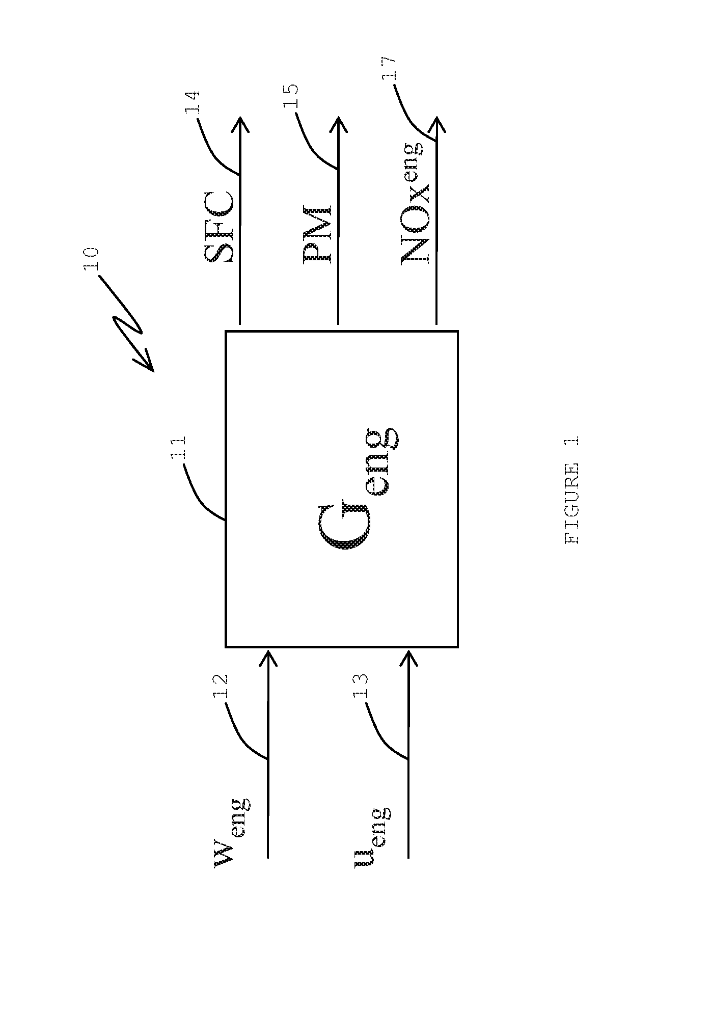
A series of FIGS. 1-4 indicate some basic elements of an engine and emission control approaches which lead up to FIGS. 5 and 6 which show examples of the present system. FIG. 1 is a diagram of a basic engine plant model system 10. Input 12 (w.sub.eng) may incorporate detected engine speed, fueling rate, ambient conditions, such as temperature and air pressure, and so on. Input 13 (u.sub.eng) may incorporate signals to actuators on the engine (e.g., variable geometry turbine (VGT), exhaust gas recirculation (EGR), throttles, fuel injection specifications, variable valve actuation (VVA), and so on). "u.sub.eng" may be regarded as one or more engine actuators. There may be a block (G.sub.eng) 11 representing an engine plant model, such as a diesel engine with a turbocharger. An output 14 may be based on SFC (specific fuel consumption, for instance, in grams per kilowatt hour) of the engine. An output 15 may indicate a PM (particulate matter) output of the engine and output 17 may indicate a NOx.sup.eng (i.e., nitrogen oxides) output of the engine. NOx may be measured in parts per million.
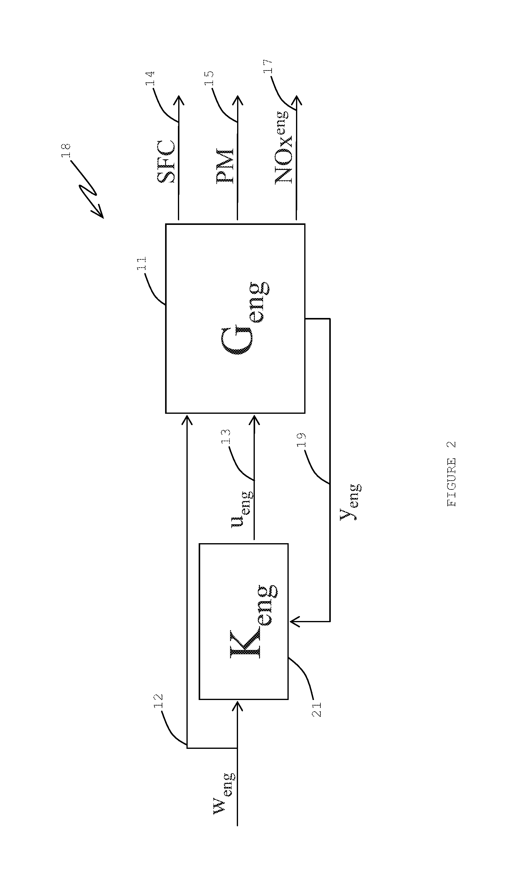
FIG. 2 is a diagram of a basic engine arrangement 18 with control but no SCR. There may be a feedback 19 (y.sub.eng) (engine sensors) from G.sub.eng 11 to a K.sub.eng block 21 which may represent an embedded computer. y.sub.eng 19 may incorporate signals from sensors for MAP, EGR flow, temperatures, NOx emissions, and so on. K.sub.eng controller 21 may incorporate one or more control algorithms. A signal 19 may represent the on-engine measurements. "y.sub.eng" may be regarded as engine sensors. A control goal may be to control the various actuators to achieve engine specific goals such as tracking desired boost pressures, fresh and/or mass air flow, EGR flow, and so forth, and indirectly be responsible for providing trade offs among SFC, PM and NOx, and other items. Often a control goal may be to minimize SFC such that legal constraints on PM and NOx are satisfied. U.sub.eng 13 (engine actuators) may incorporate actuator signals from K.sub.eng controller 21 to G.sub.eng block 11.
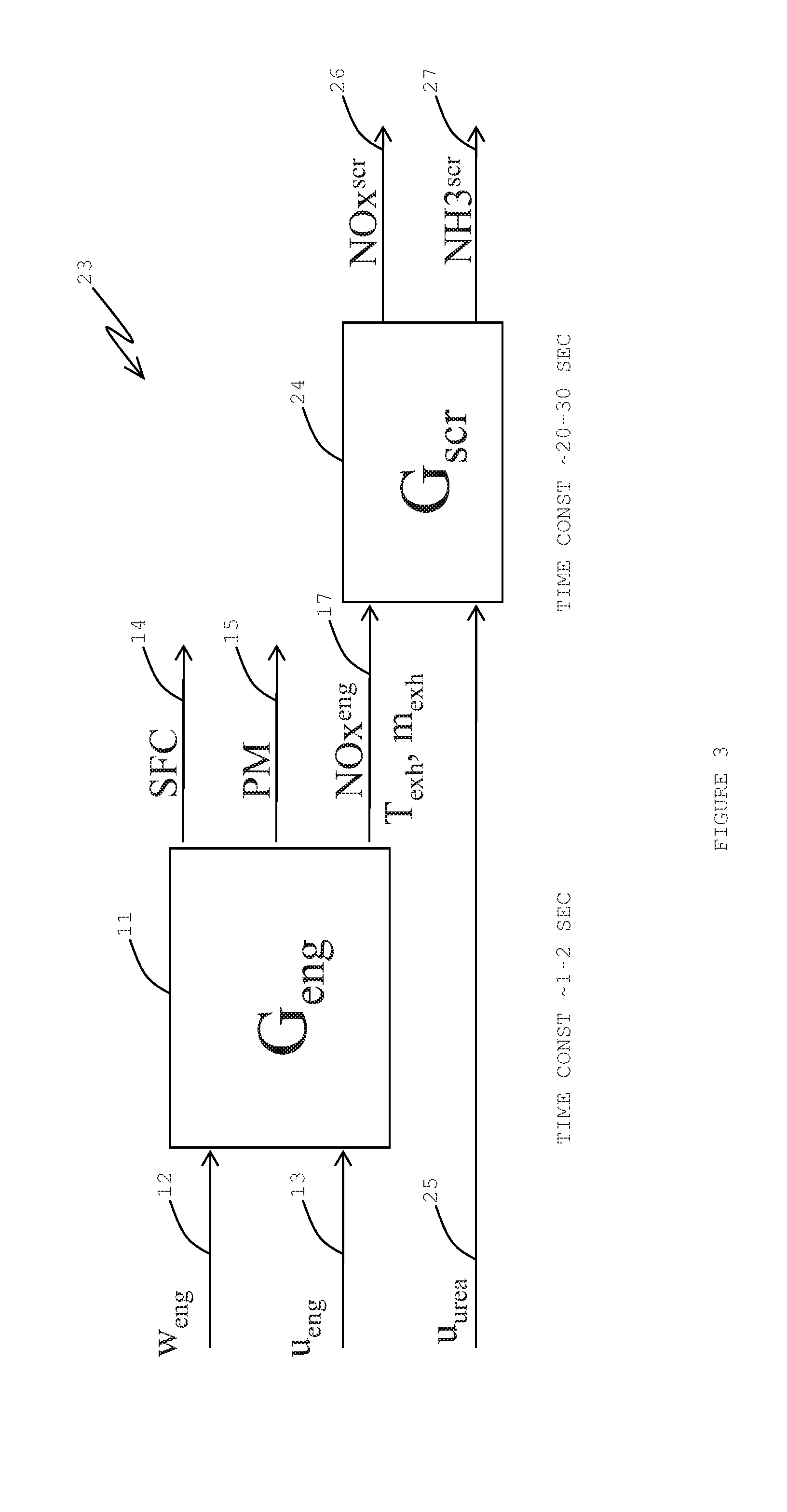
FIG. 3 is a diagram of a combined engine and SCR plant system 23. With an addition of an SCR after-treatment device 24 to the basic engine plant model 11, one may change the NOx component of the engine outputs by adding an ammonia component (NH3). There may be a w.sub.eng input 12 and a U.sub.eng input 13 to engine (G.sub.eng) block 11. The performance may in part be defined by SFC 14 and PM 15 from the G.sub.eng block 11. A signal 17 representing or indicating NOx.sup.eng, T.sub.exh (exhaust temperature) and m.sub.exh (exhaust mass) may proceed from the G.sub.eng block 11 to an SCR after-treatment (G.sub.scr) device 24. The T.sub.exh may be determined before an entry of the exhaust to device 24. System 23 may provide a u.sub.urea input signal 25 to G.sub.scr device block 24. "u.sub.urea" may be regarded as a urea solution dosing actuator. Block 24 may have an output 26 of NOx.sup.scr and an output 27 of NH3.sup.scr. Outputs 26 and 27 are the items of the system that may need to meet legal requirements relating to exhaust NOx emissions.
A time constant may be associated with the engine in block 11 and with the SCR device in block 24. The time constant of block 11 may be an amount of time (e.g., about 1-2 seconds) that is needed for changed inputs to block 11 to result in a certain amount (e.g., 63 percent) of stabilization of the response of the system to the inputs. The time constant of block 24 may be an amount of time (e.g., about 20-30 seconds) that the after-treatment device needs because of a temperature change caused by a change of inputs resulting in a change of exhaust.
Relative to the SCR device, a catalyst may be a part of the device (usually contained in a wash coat). What is injected to the exhaust gas may be a urea solution which is decomposed to ammonia and the ammonia is used as reduction agent for various chemical reactions (e.g., NOx reduction). Ammonia is adsorbed on the catalyst (e.g., a catalyst of a platinum-zeolite type)
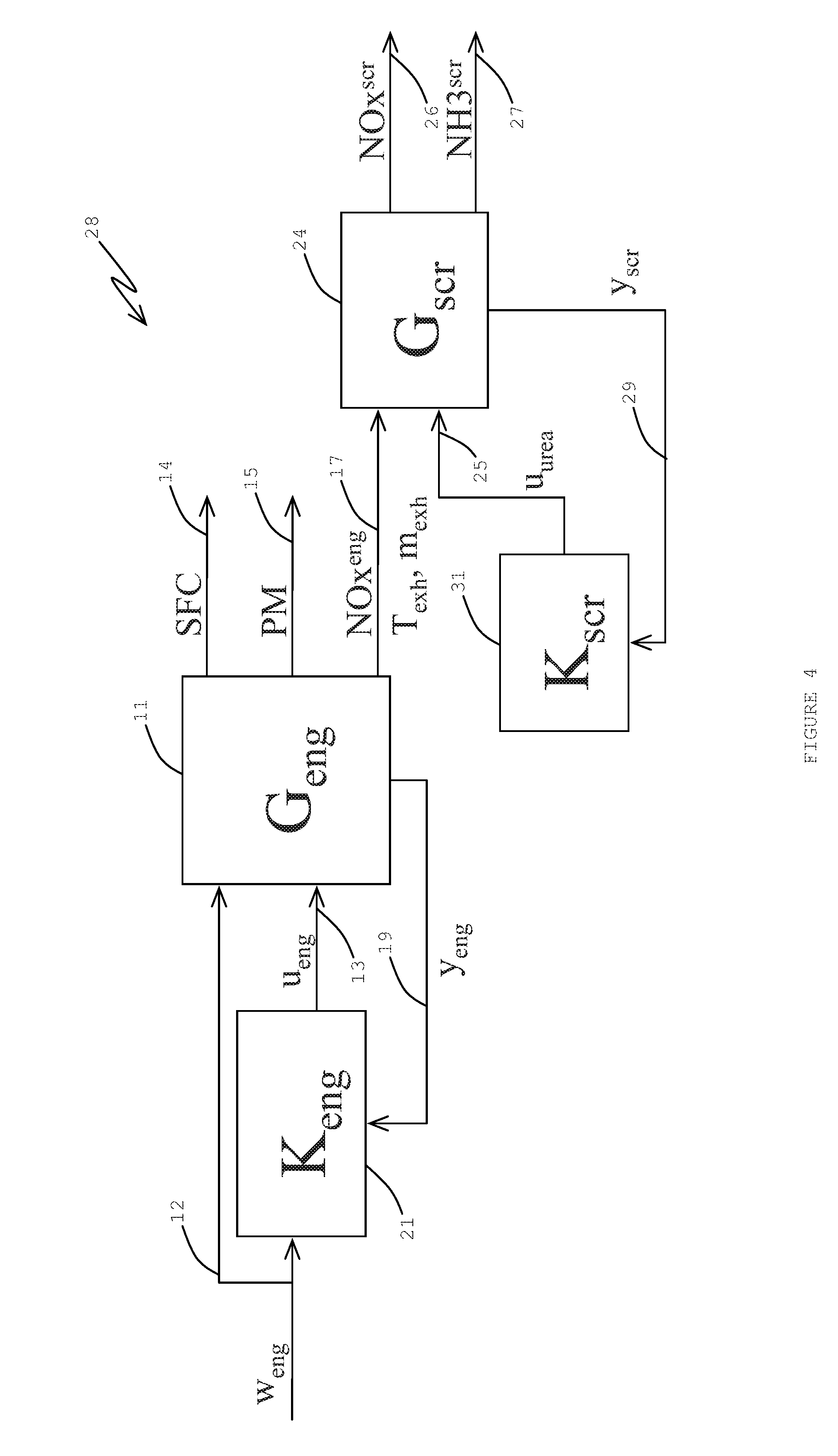
FIG. 4 is a diagram of an uncoordinated engine and SCR control system 28, having portions of system 18 of FIG. 2 and system 24 of FIG. 3, and additionally a K.sub.scr block 31 in a feedback loop of G.sub.scr block 24 with a y.sub.scr signal 29 (SCR sensors) from G.sub.scr block 24 or after-treatment mechanism 24 to a K.sub.scr or controller block 31 and a u.sub.urea signal 25 input from controller block 31 to the G.sub.scr block 24 for controlling an amount of urea solution injected into the engine exhaust 17 in the after-treatment mechanism 24. "y.sub.scr" may be regarded as SCR sensors. Such SCR sensors may be for upstream NOx (engine-out NOx), downstream NOx (tailpipe-out NOx), downstream NH3, upstream/downstream temperatures, exhaust flow, and the like. Techniques for SCR control may have the K.sub.scr 31 act on information y.sub.scr 29 of the state of the exhaust 17 entering the G.sub.scr 24 or SCR device 24. The state of the exhaust entering device 24 may be some combination of NOx, T.sub.exh and/or m.sub.exh. A state of the exhaust that is leaving the SCR device 24 may be some combination of NOx and/or NH3.
Looking at the "combined engine-SCR plant", a centralized MIMO controller appears to be a possible option. However, a dramatic difference in bandwidths (i.e., time constants of G.sub.eng block 11 and G.sub.scr block 24) may be a challenge, which suggests that a separated structure might be more practical. Generally, the SCR device 24 may decrease the engine out NOx, which could mean that there is extra capability in the engine controller K.sub.eng 21 to optimize the other items. Here, one may have a tradeoff where there is a making NOx.sup.eng higher to achieve a better SFC or vice versa.
The performance of the SCR device 24 may be governed by the urea solution dosing and also the properties of NOx.sup.eng (NOx concentration of exhaust gas), T.sub.exh (temperature of exhaust gas), and m.sub.exh (mass flow of exhaust gas) which influence the SCR device's states (temperature and NH3 coverage). The engine variables in turn may vary as a function of engine speed and fuel, ambient conditions, and engine actuators, which change much faster than a 20-30 second time constant of the G.sub.scr or SCR 24. The actuators relative to u.sub.eng may be responsible for governing engine functions in order to manipulate engine performance factors such as SFC and PM in addition to managing the SCR relevant variables of NOx.sup.eng, T.sub.exh, and m.sub.exh.
So it seems that the NOx.sup.eng, T.sub.exh, m.sub.exh might be coordinated with a urea solution dosing to enhance the overall performance of the engine-SCR system 28, but one may need to carefully consider what aspects of the control to focus on. That is, one cannot necessarily expect to be able to hold NOx.sup.eng, T.sub.exh, and m.sub.exh at a desired setpoint for a very long time considering the dynamic needs of SCR 24 and the fact that the engine actuators of G.sub.eng 11 or engine plant model 11 also have to deliver engine performance.
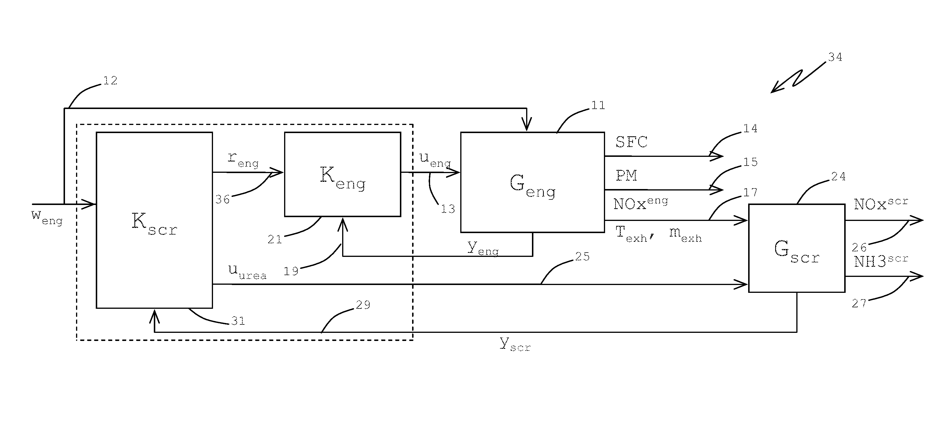
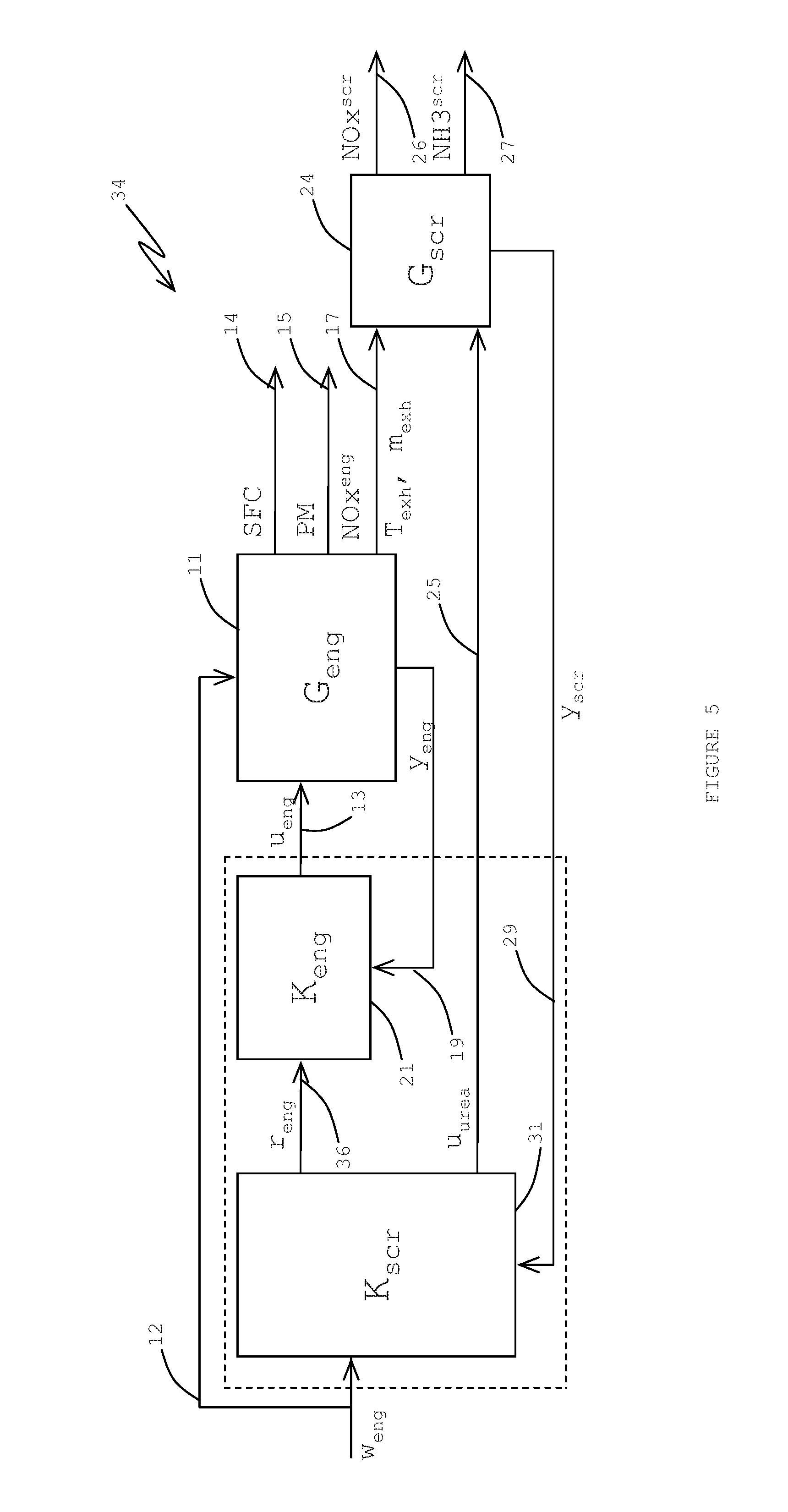
FIG. 5 is a diagram of a system 34 with cascaded coordinated control which may be considered. Cascading controllers 31 and 21 may be a part of the system's control strategy. Implicit in controller 31 may be a supervisory controller. A w.sub.eng signal 12 may enter a K.sub.scr controller block 31 and a G.sub.eng engine block 11. A r.sub.eng signal 36 may go from the K.sub.scr block 31 to the K.sub.eng block 21. A u.sub.eng signal 13 for engine actuators may go from the K.sub.eng block 21 to the G.sub.eng block 11. A signal y.sub.eng 19 from engine sensors may have information fed back from the G.sub.eng block 11 to the K.sub.eng block 21. An output SFC signal 14 and a PM signal 15 may be output from the G.sub.eng block 11. A directly or indirectly measured NOx.sup.eng, T.sub.exh, m.sub.exh signal 17 may go from the G.sub.eng block 11 to a G.sub.scr block 24. The K.sub.scr block 31 may provide an output signal u.sub.urea, 25 signal (actuator) for indicating an amount of urea solution to be injected into the SCR device G.sub.scr block 24. The G.sub.scr block 24 may feed back a y.sub.scr signal 29 with SCR sensor information about G.sub.scr 24 to the K.sub.scr block 31 for modification of setpoints, input parameters, speed, fuel, and so on, of the engine as indicated by w.sub.eng 12. The SCR device (G.sub.scr block 24) may output a NOx.sup.scr signal 26 and an NH3.sup.scr signal 27.
The r.sub.eng signal 36 may refer to the setpoints and input parameters for the engine controller (K.sub.eng) 21. The SCR controller (K.sub.scr) 31 may use the r.sub.eng signal 36 for actuation to assist in the SCR 24 control via the NOx.sup.eng, T.sub.exh and m.sub.exh signal 17.
K.sub.eng block 21 and/or K.sub.scr block 31 may each represent a model predictive control (MPC) controller. If one assumes that K.sub.scr block 31 represents an MPC controller, then one may put constraints on the r.sub.eng signal 36 so that engine control goals, such as, for example, requirements on PM, SFC and NOx.sup.eng, are respected. The present structure 34 may permit a use of the r.sub.eng signal 36 to enhance a slow transient response of the K.sub.scr block 31.
FIG. 6 is a diagram of a hierarchical coordinated control system 38. A w.sub.eng signal 12 may enter a K block 39 and a G.sub.eng block 11. A r.sub.eng signal 36 may go from the K block 39 to a K.sub.eng block 21. A u.sub.eng signal 13 may go from the K.sub.eng block 21 to the G.sub.eng block 11. A yea signal 19 may be fed back from the G.sub.eng block 11 to the K.sub.eng block 21. An output of the engine may include SFC 14 and a PM signal 15 as output from the G.sub.eng block 11. A NOx.sup.eng, T.sub.exh and m.sub.exh signal 17 may go from the G.sub.eng block 11 to a G.sub.scr block 24. An r.sub.scr signal 41 may go from the K block 39 to a K.sub.scr block 31. A u.sub.urea signal 25 may go from the K.sub.scr block 31 to the G.sub.scr block 24. Outputs from the SCR device G.sub.scr block 24 may include a NOx.sup.scr signal 26 and an NH3.sup.scr signal 27.
The control strategy for system 38 of FIG. 6 may have a hierarchical structure with the controller K.sub.scr 31 dedicated to the G.sub.scr 24. Here, the K block 39 may be a supervisor controller or coordinator which manipulates the setpoints w.sub.eng, r.sub.eng, r.sub.scr and so on for the local controllers K.sub.eng 21 and K.sub.scr 31, so that the prescribed goals are achieved, i.e., namely, the requirements for NOx.sup.scr, NH3.sup.scr, PM, SFC, and so forth. K block 39, K.sub.eng block 21 and/or K.sub.scr block 31 may each represent an MPC controller.
Model predictive control (MPC) is a control approach that appears to have been successfully applied in many industrial control applications. MPC appears suitable for applications where it may be necessary dynamically coordinate several actuators to drive several controlled variables. Such systems may be known as multivariable. MPC appears able to include constraints on various signals in a control loop systematically. The ability to handle the constrained multivariable dynamical system in a systematic way may be the key factor which increases popularity of MPC.
MPC may use a dynamical model of the controlled system to predict future behavior of a controlled technology or process. Based on this prediction and based on defined optimality criteria, MPC may compute an optimal control signal by solving a constrained optimization problem. This optimization problem should be solved at each sampling period to reject the disturbances and to ensure certain degree of robustness. An example of such optimization problem is expression (1). Uopt=arg min J(U,x,p)s.t.g(U,x,p)<=0 (1) In expression (1), Uopt is the optimal control signal trajectory, J(U,x,p) is MPC cost function, g(U,x,p) represents MPC constraints, U is the optimization variable, x may be the internal state of the controlled system and p may represent various parameters. The cost function J(U,x,p) may be a weighted sum of various penalties, for example, a sum of squared 2nd norms of tracking error over the prediction horizon, sum of squared 2nd norms of actuator movements, and so on. Constraints g(U,x,p) may include limits for actuators and for various controlled variables over the prediction horizon.
The efficiency of the solver appears as a key factor limiting range of applications with fast sampling periods (in combination with performance of computation environment), e.g., automotive applications. Recent development of solvers for a fast MPC may enable an application of MPC technology for relatively fast automotive systems, for example, an engine air path or emissions control as it is briefly described herein. Suitable solvers for fast MPC may be based on an on-line solution or explicit solution of a parametric optimization problem (1). To achieve the best efficiency, the solvers for MPC may be standard, directly tailored for MPC or directly tailored for a particular MPC application. The on-line solvers may be based on active set (standard formulation, gradient projection, and so forth), interior point, and so on. The explicit solution may be based on multi-parametric approach, primal-dual feasibility approach, and so on.
An uncoordinated MPC control may be illustrated by the control structure shown in FIG. 4 (block or system 28). One or both controllers 21 and 31 may be implemented as an MPC. The objective of engine air path controller K.sub.eng 21 is to ensure that the selected controlled variables will follow their setpoints while all given constraints will be satisfied. The controlled variables 19 (engine sensors) may be, for example, any combination from the following set: boost pressure, exhaust gas recirculation flow, lambda sensor, exhaust manifold pressure, total engine air flow, turbocharger speed, and so on. The engine actuators 13 may be exhaust gas recirculation valve, turbocharger actuator, wastegate valve, throttle valve, start of injection, and so forth. The considered constraints may be, for example, upper and lower limits of actuator positions, a limit for lambda sensor, a limit for turbocharger speed, and so on. An objective for the controller K.sub.scr 31 is to control tailpipe emissions. A manipulated variable for K.sub.scr 31 may be an amount of injected urea solution 25 to the engine exhaust gas stream. Controlled variables 29 (SCR sensors) may be tailpipe emissions, namely NOx concentration 26, and PM and ammonia slip 27.
A cascaded coordinated MPC control may be illustrated structure or system 34 shown by FIG. 5. The structure may reflect the fact that the SCR system 24 is much slower that the engine air path. Therefore, it may be beneficial to configure two MPC controllers 21 and 31 in the cascade structure 34. The engine controller (K.sub.eng) 21 may be configured to ensure basic stability of the engine air path. The additional degrees of freedom of controller 21 may be then used to influence engine exhaust gas properties so that the downstream SCR device 24 can work effectively. Controlled variables (y.sub.eng) 19 (engine sensors) of K.sub.eng controller 21 may be the same as those in the uncoordinated case but it may be beneficial to add other controlled variables 17 (after-treatment sensors) which are directly related to SCR device operation and can be influenced by the engine actuators, i.e., NOx concentration and exhaust gas temperature. The SCR controller (K.sub.scr) 31 may be configured as a coordinator of K.sub.eng controller 21. K.sub.scr controller 31 may be slower than K.sub.eng controller 21 and may provide setpoints 36 for K.sub.eng controller 21 to ensure efficient operation (NOx conversion) of SCR device 24. The controlled variables (y.sub.scr) 29 (SCR sensors) of K.sub.scr controller 31 may be the same as those in the uncoordinated case, i.e., NOx concentration 26 and ammonia slip 27. The manipulated variable may be an amount of injected urea solution 25 but also a selected subset of setpoints 36 for K.sub.eng controller 21, e.g., engine exhaust NOx concentration 17 setpoint and engine exhaust gas temperature 17 setpoint.
The configuration, structure or system 38 is shown in FIG. 6. Control structure 38 may combine uncoordinated MPC control and cascade coordinated control. There may be two local controllers K.sub.eng 21 and K.sub.scr 31. Controllers K.sub.eng 21 and K.sub.scr 31 may be coordinated by a central coordinator or controller K 39. One, two or three of the controllers 21, 31 and 39 may be MPC controllers. The control or actuators (u.sub.eng) 13 and controlled variables (y.sub.eng) 19 (engine sensors) of K.sub.eng controller 21 may be the same as those in cascaded coordinated MPC control. The r.sub.eng setpoints 36 for the controlled yes signals 19 (engine sensors) may be computed by controller or coordinator K 39. A manipulated variable of controller K.sub.scr 31 may be an amount of injected urea solution (u.sub.urea) 25. The controlled variables (y.sub.scr) 29 (SCR sensors) of K.sub.scr controller 31 may be NOx emissions 26 and NH3 slip 27. Setpoints (r.sub.scr) 41 for the controlled variables 29 may be computed by coordinator K 39. Coordinator K 39 may be configured so that the overall efficiency of both engine and SCR device are maximized while minimizing the operation costs.
A recap in view of FIGS. 1-6 may be noted. A selective catalytic reduction control system may incorporate a diesel engine or a model of the engine, a selective catalytic reduction exhaust after-treatment mechanism for connection to the engine, an engine controller, and a selective catalytic reduction controller connected to the selective catalytic reduction exhaust after-treatment mechanism and to the engine controller. The engine controller and the selective catalytic reduction controller may provide coordinated control of the engine and selective catalytic reduction selective catalytic reduction exhaust after-treatment mechanism to control an amount of pollutants in an exhaust emission from the engine. The items noted herein may be modeled.
The engine controller and the selective catalytic reduction controller may provide coordinated control of the engine and selective catalytic reduction exhaust after-treatment mechanism to optimize selective catalytic reduction of pollutants in the exhaust emission so as to reduce specific fuel consumption and/or particulate matter emission. The engine controller and the selective catalytic reduction controller may be model predictive controllers.
The selective catalytic reduction exhaust after-treatment mechanism may provide a catalyst into the exhaust emission for selective catalytic reduction of the pollutants in the exhaust emission. The pollutants may have NOx. The selective catalytic reduction may incorporate reducing NOx in the exhaust emission.
An amount of urea solution, which may be decomposed to ammonia injected into the exhaust emission, may be determined by a signal from the selective catalytic reduction controller. The signal may determine the amount of urea solution according to information about the pollutants in the exhaust emission. Information about the pollutants may have an indication of magnitude of NOx in the exhaust emission.
An output signal may be provided by the selective catalytic reduction controller to the engine controller. The output signal may be for indicating the information about the exhaust. The information about the exhaust may incorporate indicating an amount of NOx in the exhaust emission, exhaust mass and/or a temperature of the exhaust.
An approach for selective catalytic reduction, may incorporate providing a first model of a diesel engine and associated components, a second model of an exhaust after-treatment device coupled to an exhaust of the first model of the diesel engine, an engine controller connected to the first model of the diesel engine, and a selective catalytic reduction controller connected to the second model of the exhaust after-treatment device. The approach may also incorporate simulating a treating an exhaust of the first model with selective catalytic reduction as provided by the second model to reduce pollutants in the exhaust, simulating an operation of the first model to increase fuel efficiency, and coordinating the first and second models in conjunction with the first and second controllers, respectively, to allow for a reduction of pollutants and an increase the fuel efficiency. The controllers may be model predictive controllers.
A selective catalytic reduction of pollutants may incorporate injecting a prescribed amount of urea solution into the exhaust. The prescribed amount of urea solution may be determined by coordinated control of the first and second models and the selective catalytic reduction to allow for the reduction of pollutants such as NOx, and increased fuel efficiency of the engine.
The approach may further incorporate obtaining information about a reduction of the amount of NOx with ammonia decomposed from the urea solution. The amount of urea solution provided to the exhaust may be prescribed according to the information about the reduction of NOx with ammonia decomposed from the urea solution.
An engine emissions reduction system may incorporate an exhaust after-treatment device, and a system controller connected to the exhaust after-treatment device. The exhaust after-treatment device may incorporate a coupling for connection to an exhaust of a diesel engine. The system controller may be connected to the engine and to the exhaust after-treatment device. The system controller may coordinate control of the engine and the exhaust after-treatment device to provide selective catalytic reduction of polluting emissions from the engine.
The system controller may incorporate a supervisory controller, an engine controller connected to the supervisory controller and the engine, and a selective catalytic reduction controller connected to the supervisory controller and the exhaust after-treatment device. The system controller may coordinate control of the engine and the exhaust after-treatment device to further provide increased fuel efficiency of the engine. The polluting emissions may have NOx. The selective catalytic reduction may neutralize the NOx with an addition of urea solution to the emissions.
The controllers may be model predictive controllers. The selective catalytic reduction controller may provide a signal indicating an amount of urea solution to be provided to the polluting emissions. The signal may be conveyed to the exhaust after-treatment device for releasing the amount of urea solution into the polluting emissions exhaust of the engine. At an exhaust output downstream from the exhaust after-treatment device, the amount of urea solution released into the exhaust may be determined by the signal from the selective catalyst reduction controller that indicates the amounts of NOx and NH3 in the exhaust and amounts of NOx and NH3 permitted in the exhaust by applicable regulations on emissions.
In the present specification, some of the matter may be of a hypothetical or prophetic nature although stated in another manner or tense.
Although the present system and/or approach has been described with respect to at least one illustrative example, many variations and modifications will become apparent to those skilled in the art upon reading the specification. It is therefore the intention that the appended claims be interpreted as broadly as possible in view of the related art to include all such variations and modifications.
* * * * *
References
D00000
D00001
D00002
D00003
D00004
D00005
D00006
XML
uspto.report is an independent third-party trademark research tool that is not affiliated, endorsed, or sponsored by the United States Patent and Trademark Office (USPTO) or any other governmental organization. The information provided by uspto.report is based on publicly available data at the time of writing and is intended for informational purposes only.
While we strive to provide accurate and up-to-date information, we do not guarantee the accuracy, completeness, reliability, or suitability of the information displayed on this site. The use of this site is at your own risk. Any reliance you place on such information is therefore strictly at your own risk.
All official trademark data, including owner information, should be verified by visiting the official USPTO website at www.uspto.gov. This site is not intended to replace professional legal advice and should not be used as a substitute for consulting with a legal professional who is knowledgeable about trademark law.