Dual suspension seating assembly
Line , et al.
U.S. patent number 10,286,818 [Application Number 15/591,891] was granted by the patent office on 2019-05-14 for dual suspension seating assembly. This patent grant is currently assigned to Ford Global Technologies, LLC. The grantee listed for this patent is Ford Global Technologies, LLC. Invention is credited to David Andree, S. M. Akbar Berry, Rodney Charles Brinker, Carol Diane Casey, Daniel Ferretti, John Wayne Jaranson, Michael Kolich, Marcos Silva Kondrad, Johnathan Andrew Line.
View All Diagrams
| United States Patent | 10,286,818 |
| Line , et al. | May 14, 2019 |
Dual suspension seating assembly
Abstract
A vehicle seating assembly includes a seatback and a seat base. The seat base is operably coupled to the seatback. The seat base includes a first suspension assembly and a second suspension assembly. The first suspension assembly includes a seat pan assembly and a seat cushion assembly. The seat cushion assembly is positioned above the seat pan assembly. The second suspension assembly includes a plurality of independent thigh supports operably coupled to a forward portion of the seat pan.
| Inventors: | Line; Johnathan Andrew (Northville, MI), Ferretti; Daniel (Commerce Township, MI), Jaranson; John Wayne (Dearborn, MI), Kondrad; Marcos Silva (Macomb, MI), Kolich; Michael (Windsor, CA), Berry; S. M. Akbar (Windsor, CA), Casey; Carol Diane (Dearborn, MI), Andree; David (Commerce Township, MI), Brinker; Rodney Charles (Eastpointe, MI) | ||||||||||
|---|---|---|---|---|---|---|---|---|---|---|---|
| Applicant: |
|
||||||||||
| Assignee: | Ford Global Technologies, LLC
(Dearborn, MI) |
||||||||||
| Family ID: | 59855247 | ||||||||||
| Appl. No.: | 15/591,891 | ||||||||||
| Filed: | May 10, 2017 |
Prior Publication Data
| Document Identifier | Publication Date | |
|---|---|---|
| US 20170267141 A1 | Sep 21, 2017 | |
Related U.S. Patent Documents
| Application Number | Filing Date | Patent Number | Issue Date | ||
|---|---|---|---|---|---|
| 15096364 | Apr 12, 2016 | 10046681 | |||
| 15071947 | Mar 16, 2016 | 9849817 | |||
| Current U.S. Class: | 1/1 |
| Current CPC Class: | B60N 2/99 (20180201); B60N 2/0284 (20130101); B60N 2/54 (20130101); B60N 2/72 (20130101); B60N 2/62 (20130101); B60N 2/502 (20130101) |
| Current International Class: | B60N 2/62 (20060101); B60N 2/02 (20060101); B60N 2/50 (20060101); B60N 2/54 (20060101); B60N 2/90 (20180101) |
References Cited [Referenced By]
U.S. Patent Documents
| 616178 | December 1898 | Barron |
| 771773 | October 1904 | Feely |
| 1125155 | January 1915 | Nunn |
| 2272505 | February 1942 | Biggs |
| 2661050 | December 1953 | Felter |
| 2725921 | December 1955 | Markin |
| 2834606 | May 1958 | Bertrand |
| 2938570 | May 1960 | Flajole |
| 2958369 | November 1960 | Pitts et al. |
| 3007738 | November 1961 | Gardel et al. |
| 3018133 | January 1962 | Mills |
| 3273877 | September 1966 | Geller et al. |
| 3330598 | July 1967 | Whiteside |
| 3403938 | October 1968 | Cramer et al. |
| 3481327 | December 1969 | Drennen |
| 3512605 | May 1970 | McCorkle |
| 3520327 | July 1970 | Claydon et al. |
| 3550953 | December 1970 | Neale |
| 3592508 | July 1971 | Druseikis |
| 3612607 | October 1971 | Lohr |
| 3632166 | January 1972 | Lohr |
| 3663057 | May 1972 | Lohr et al. |
| 3669492 | June 1972 | Peterson |
| 3779577 | December 1973 | Wilfert |
| 3792897 | February 1974 | Alson |
| 3795021 | March 1974 | Moniot |
| 3813151 | May 1974 | Cadiou |
| 3833257 | September 1974 | Dove |
| 3877749 | April 1975 | Sakurai et al. |
| 3880462 | April 1975 | Mednick |
| 3883173 | May 1975 | Shephard |
| 3885831 | May 1975 | Rasmussen |
| 3915421 | October 1975 | Le Forestier |
| 3929374 | December 1975 | Hogan et al. |
| 3954245 | May 1976 | Costin |
| 4017118 | April 1977 | Cawley |
| 4018477 | April 1977 | Hogan |
| 4058342 | November 1977 | Ettridge |
| 4115170 | September 1978 | Sanson |
| 4190286 | February 1980 | Bentley |
| 4205877 | June 1980 | Ettridge |
| 4225989 | October 1980 | Corbett et al. |
| 4306322 | December 1981 | Young et al. |
| 4324431 | April 1982 | Murphy et al. |
| 4334709 | June 1982 | Akiyama et al. |
| 4353595 | October 1982 | Kaneko et al. |
| 4366985 | January 1983 | Leffler |
| 4415203 | November 1983 | Cawley |
| 4440443 | April 1984 | Nordskog |
| 4444430 | April 1984 | Yoshida et al. |
| 4452485 | June 1984 | Schuster |
| 4467484 | August 1984 | Nagatake et al. |
| 4491364 | January 1985 | Hattori et al. |
| 4491365 | January 1985 | Murakami |
| 4518201 | May 1985 | Wahlmann et al. |
| 4522445 | June 1985 | Goldner et al. |
| 4541669 | September 1985 | Goldner |
| 4580837 | April 1986 | Bayley |
| 4583255 | April 1986 | Mogaki et al. |
| 4583781 | April 1986 | Hatsutta et al. |
| 4592588 | June 1986 | Isono et al. |
| 4609221 | September 1986 | Bottcher |
| 4616676 | October 1986 | Adams et al. |
| 4616874 | October 1986 | Pietsch et al. |
| 4629248 | December 1986 | Mawbey |
| 4629253 | December 1986 | Williams |
| 4634179 | January 1987 | Hashimoto et al. |
| 4655505 | April 1987 | Kashiwamura et al. |
| 4664444 | May 1987 | Murphy |
| 4668014 | May 1987 | Boisset |
| 4693513 | September 1987 | Heath |
| 4707027 | November 1987 | Horvath et al. |
| 4718723 | January 1988 | Bottemiller |
| 4720141 | January 1988 | Sakamoto et al. |
| 4720146 | January 1988 | Mawbey et al. |
| 4726086 | February 1988 | McEvoy |
| 4752982 | June 1988 | Jones et al. |
| 4753479 | June 1988 | Hatsutta et al. |
| 4767155 | August 1988 | Kousaka et al. |
| 4773703 | September 1988 | Krugener et al. |
| 4775185 | October 1988 | Scholin et al. |
| 4781413 | November 1988 | Shumack, Jr. |
| 4790592 | December 1988 | Busso et al. |
| 4792186 | December 1988 | Benjamin et al. |
| 4796313 | January 1989 | DiMatteo et al. |
| 4822092 | April 1989 | Sweers |
| 4833614 | May 1989 | Saitoh et al. |
| 4840429 | June 1989 | Stockl |
| 4856844 | August 1989 | Isono |
| 4858992 | August 1989 | LaSota |
| 4861104 | August 1989 | Malak |
| 4884843 | December 1989 | DeRees |
| 4893367 | January 1990 | Heimreid et al. |
| 4915447 | April 1990 | Shovar |
| 4938529 | July 1990 | Fourrey |
| 4965899 | October 1990 | Sekido et al. |
| 4966410 | October 1990 | Bishai |
| 4971380 | November 1990 | Cote et al. |
| 5013089 | May 1991 | Abu-Isa et al. |
| 5018790 | May 1991 | Jay |
| 5020852 | June 1991 | Marion |
| 5022709 | June 1991 | Marchino |
| 5050930 | September 1991 | Schuster et al. |
| 5054845 | October 1991 | Vogel |
| 5054856 | October 1991 | Wang |
| 5067772 | November 1991 | Koa |
| 5082326 | January 1992 | Sekido et al. |
| 5096529 | March 1992 | Baker |
| 5104189 | April 1992 | Hanai et al. |
| 5108150 | April 1992 | Stas et al. |
| 5112018 | May 1992 | Wahls |
| 5120109 | June 1992 | Rangoni |
| 5127708 | July 1992 | Kishi et al. |
| 5129704 | July 1992 | Kishi et al. |
| 5145232 | September 1992 | Dal Monte |
| 5171062 | December 1992 | Courtois |
| 5174526 | December 1992 | Kanigowski |
| 5186494 | February 1993 | Shimose |
| 5190348 | March 1993 | Colasanti |
| 5203608 | April 1993 | Tame |
| 5222784 | June 1993 | Hamelin |
| 5243722 | September 1993 | Gusakov |
| 5263765 | November 1993 | Nagashima et al. |
| 5285754 | February 1994 | Bell |
| 5318344 | June 1994 | Wang |
| 5320409 | June 1994 | Katoh et al. |
| 5323740 | June 1994 | Daily et al. |
| 5364164 | November 1994 | Kuranami |
| 5370443 | December 1994 | Maruyama |
| 5375569 | December 1994 | Santella |
| 5380063 | January 1995 | Dauphin |
| 5443303 | August 1995 | Bauer et al. |
| 5458365 | October 1995 | Rogers et al. |
| 5518294 | May 1996 | Ligon, Sr. et al. |
| 5544942 | August 1996 | Vu Khac et al. |
| 5547214 | August 1996 | Zimmerman, II et al. |
| 5560681 | October 1996 | Dixon et al. |
| 5570716 | November 1996 | Kamen et al. |
| 5588708 | December 1996 | Rykken et al. |
| 5597203 | January 1997 | Hubbard |
| 5609394 | March 1997 | Ligon, Sr. et al. |
| 5647635 | July 1997 | Aumond et al. |
| 5658050 | August 1997 | Lorbiecki |
| 5662384 | September 1997 | O'Neill et al. |
| 5678891 | October 1997 | O'Neill et al. |
| 5681084 | October 1997 | Yoneda |
| 5690387 | November 1997 | Sarti |
| 5692802 | December 1997 | Aufrere et al. |
| 5707109 | January 1998 | Massara et al. |
| 5738368 | April 1998 | Hammond et al. |
| 5755493 | May 1998 | Kodaverdian |
| 5758924 | June 1998 | Vishey |
| 5769489 | June 1998 | Dellanno |
| 5772280 | June 1998 | Massara |
| 5775778 | July 1998 | Riley et al. |
| 5785669 | July 1998 | Proctor et al. |
| 5799971 | September 1998 | Asada |
| 5803490 | September 1998 | Seventko et al. |
| 5815393 | September 1998 | Chae |
| 5823620 | October 1998 | Le Caz |
| 5826938 | October 1998 | Yanase et al. |
| 5836648 | November 1998 | Karschin et al. |
| 5860699 | January 1999 | Weeks |
| 5863092 | January 1999 | Kifer |
| 5868450 | February 1999 | Hashimoto |
| 5882073 | March 1999 | Burchi et al. |
| 5893609 | April 1999 | Schmidt |
| 5895070 | April 1999 | Crimmins et al. |
| 5902014 | May 1999 | Dinkel et al. |
| 5906586 | May 1999 | Graham |
| 5913568 | June 1999 | Brightbill et al. |
| 5944341 | August 1999 | Kimura et al. |
| 5951039 | September 1999 | Severinski et al. |
| 5967608 | October 1999 | Van Sickle |
| 5975629 | November 1999 | Lorbiecki |
| 5975637 | November 1999 | Geuss et al. |
| 5979985 | November 1999 | Bauer et al. |
| 5983940 | November 1999 | Smith |
| 5988674 | November 1999 | Kimura et al. |
| 6019387 | February 2000 | Jost |
| 6024378 | February 2000 | Fu |
| 6024406 | February 2000 | Charras et al. |
| 6030040 | February 2000 | Schmid et al. |
| 6050635 | April 2000 | Pajon et al. |
| 6056366 | May 2000 | Haynes et al. |
| 6062642 | May 2000 | Sinnhuber et al. |
| 6068339 | May 2000 | Linzalone |
| 6079781 | June 2000 | Tilley |
| 6088642 | July 2000 | Finkelstein et al. |
| 6106071 | August 2000 | Aebischer et al. |
| 6106163 | August 2000 | Inana et al. |
| 6109690 | August 2000 | Wu et al. |
| 6145925 | November 2000 | Eksin et al. |
| 6155593 | December 2000 | Kimura et al. |
| 6158812 | December 2000 | Bonke |
| 6161231 | December 2000 | Kraft et al. |
| 6179379 | January 2001 | Andersson |
| 6189966 | February 2001 | Faust et al. |
| 6196627 | March 2001 | Faust et al. |
| 6199252 | March 2001 | Masters et al. |
| 6199900 | March 2001 | Zeigler |
| 6199951 | March 2001 | Zeile et al. |
| 6203105 | March 2001 | Rhodes, Jr. |
| 6206466 | March 2001 | Komatsu |
| 6217062 | April 2001 | Breyvogel et al. |
| 6217118 | April 2001 | Heilig |
| 6220661 | April 2001 | Peterson |
| 6224150 | May 2001 | Eksin et al. |
| 6231068 | May 2001 | White, Jr. et al. |
| 6234518 | May 2001 | Ryl et al. |
| 6273810 | August 2001 | Rhodes, Jr. et al. |
| 6296308 | October 2001 | Cosentino et al. |
| 6302431 | October 2001 | Sasaki et al. |
| 6312050 | November 2001 | Eklind |
| 6341797 | January 2002 | Seo |
| 6349993 | February 2002 | Walsh |
| 6352304 | March 2002 | Sorgenfrei |
| 6352310 | March 2002 | Schmidt et al. |
| 6357066 | March 2002 | Pierce |
| 6357789 | March 2002 | Harada et al. |
| 6357827 | March 2002 | Brightbill et al. |
| 6364414 | April 2002 | Specht |
| 6375269 | April 2002 | Maeda et al. |
| 6382720 | May 2002 | Franklin et al. |
| 6386577 | May 2002 | Kan et al. |
| 6390557 | May 2002 | Asano |
| 6394525 | May 2002 | Seibold |
| 6394546 | May 2002 | Knoblock et al. |
| 6398299 | June 2002 | Angerer et al. |
| 6398306 | June 2002 | Mack |
| 6419317 | July 2002 | Westrich et al. |
| 6425602 | July 2002 | Al-Amin et al. |
| 6431734 | August 2002 | Curry |
| 6439597 | August 2002 | Harada et al. |
| 6450571 | September 2002 | Canni et al. |
| 6454353 | September 2002 | Knaus |
| 6457741 | October 2002 | Seki et al. |
| 6474733 | November 2002 | Heilig et al. |
| 6523892 | February 2003 | Kage et al. |
| 6523902 | February 2003 | Robinson |
| 6530622 | March 2003 | Ekern et al. |
| 6550856 | April 2003 | Ganser et al. |
| 6554365 | April 2003 | Karschin et al. |
| 6557887 | May 2003 | Wohllebe |
| 6561540 | May 2003 | Hasegawa et al. |
| 6565150 | May 2003 | Fischer et al. |
| 6565153 | May 2003 | Hensel et al. |
| 6568754 | May 2003 | Norton et al. |
| 6578911 | June 2003 | Harada et al. |
| 6588838 | July 2003 | Dick, Jr. et al. |
| 6612610 | September 2003 | Aoki et al. |
| 6616177 | September 2003 | Thomas et al. |
| 6619605 | September 2003 | Lambert |
| 6619737 | September 2003 | Kunkel et al. |
| 6629715 | October 2003 | Oh et al. |
| 6637818 | October 2003 | Williams |
| 6672666 | January 2004 | Stiller et al. |
| 6682059 | January 2004 | Daniels et al. |
| 6682140 | January 2004 | Minuth et al. |
| 6695406 | February 2004 | Plant |
| 6698832 | March 2004 | Boudinot |
| 6719373 | April 2004 | Zimmermann |
| 6726280 | April 2004 | Liao |
| 6733064 | May 2004 | Fox et al. |
| 6736452 | May 2004 | Aoki et al. |
| 6746077 | June 2004 | Klukowski |
| 6758522 | July 2004 | Ligon, Sr. et al. |
| 6779560 | August 2004 | Reis |
| 6786542 | September 2004 | Nuzzarello |
| 6802563 | October 2004 | Mysliwiec et al. |
| 6808230 | October 2004 | Buss et al. |
| 6811219 | November 2004 | Hudswell et al. |
| 6820640 | November 2004 | Hand et al. |
| 6820930 | November 2004 | Dellanno |
| 6824212 | November 2004 | Malsch et al. |
| 6848742 | February 2005 | Aoki et al. |
| 6854869 | February 2005 | Fernandez |
| 6860559 | March 2005 | Schuster, Sr. et al. |
| 6860564 | March 2005 | Reed et al. |
| 6866339 | March 2005 | Itoh |
| 6869140 | March 2005 | White et al. |
| 6890029 | May 2005 | Svantesson |
| 6890030 | May 2005 | Wilkerson et al. |
| 6899399 | May 2005 | Ali et al. |
| 6908151 | June 2005 | Meeker et al. |
| 6912748 | July 2005 | VanSickle |
| 6938953 | September 2005 | Haland et al. |
| 6955399 | October 2005 | Hong |
| 6962392 | November 2005 | O'Connor |
| 6988770 | January 2006 | Witchie |
| 6991256 | January 2006 | Henderson et al. |
| 6991289 | January 2006 | House |
| 6997473 | February 2006 | Tanase et al. |
| 7025423 | April 2006 | Fujita et al. |
| 7040699 | May 2006 | Curran et al. |
| 7055904 | June 2006 | Skelly et al. |
| 7059678 | June 2006 | Taylor |
| 7072764 | July 2006 | Donath et al. |
| 7093898 | August 2006 | Ladron De Guevara |
| 7100978 | September 2006 | Ekern et al. |
| 7100992 | September 2006 | Bargheer et al. |
| 7108322 | September 2006 | Erker |
| 7111901 | September 2006 | Schlierf et al. |
| 7125077 | October 2006 | Frank |
| 7131694 | November 2006 | Buffa |
| 7131756 | November 2006 | Leslie et al. |
| 7134686 | November 2006 | Tracht et al. |
| 7140682 | November 2006 | Jaeger et al. |
| 7152920 | December 2006 | Sugiyama et al. |
| 7159934 | January 2007 | Farquhar et al. |
| 7159938 | January 2007 | Shiraishi |
| 7185950 | March 2007 | Pettersson et al. |
| 7195274 | March 2007 | Tracht |
| 7195277 | March 2007 | Tracht et al. |
| 7213876 | May 2007 | Stoewe |
| 7213883 | May 2007 | Charnitski |
| 7216915 | May 2007 | Kammerer et al. |
| 7229118 | June 2007 | Saberan et al. |
| 7229129 | June 2007 | White et al. |
| 7234771 | June 2007 | Nakhla |
| 7261371 | August 2007 | Thunissen et al. |
| 7267363 | September 2007 | Tredez |
| 7284768 | October 2007 | Tracht |
| 7290791 | November 2007 | Tracht |
| 7293831 | November 2007 | Greene |
| 7311681 | December 2007 | Vaccarella |
| 7316215 | January 2008 | Nino et al. |
| 7322651 | January 2008 | Makhsous et al. |
| 7325878 | February 2008 | Dehli |
| 7341309 | March 2008 | Penley et al. |
| 7344189 | March 2008 | Reed et al. |
| 7347444 | March 2008 | Wheelwright |
| 7350803 | April 2008 | Abramczyk et al. |
| 7350859 | April 2008 | Klukowski |
| 7350865 | April 2008 | Pearse |
| 7357412 | April 2008 | Tracht et al. |
| 7357454 | April 2008 | Schiener et al. |
| 7382240 | June 2008 | Egelhaaf |
| 7387339 | June 2008 | Bykov et al. |
| 7393005 | July 2008 | Inazu et al. |
| 7401852 | July 2008 | Humer et al. |
| 7413253 | August 2008 | Karlberg |
| 7425034 | September 2008 | Bajic et al. |
| 7441797 | October 2008 | Tracht et al. |
| 7441838 | October 2008 | Patwardhan |
| 7445292 | November 2008 | Moule |
| 7467823 | December 2008 | Hartwich |
| 7478869 | January 2009 | Lazanja et al. |
| 7481489 | January 2009 | Demick |
| 7488040 | February 2009 | Dozsa-Farkas |
| 7506924 | March 2009 | Bargheer et al. |
| 7506938 | March 2009 | Brennan et al. |
| 7517015 | April 2009 | Terada et al. |
| 7517024 | April 2009 | Cvek |
| 7523888 | April 2009 | Ferry et al. |
| 7530633 | May 2009 | Yokota et al. |
| 7540529 | June 2009 | Tracht et al. |
| 7543888 | June 2009 | Kuno |
| 7547068 | June 2009 | Davis |
| 7562934 | July 2009 | Swan et al. |
| 7578552 | August 2009 | Bajic et al. |
| 7578554 | August 2009 | Lee et al. |
| 7597398 | October 2009 | Lindsay |
| 7604294 | October 2009 | Santamaria |
| 7611199 | November 2009 | Michalak et al. |
| 7614693 | November 2009 | Ito |
| 7637568 | December 2009 | Meeker et al. |
| 7640090 | December 2009 | Uchida et al. |
| 7641281 | January 2010 | Grimm |
| 7668329 | February 2010 | Matsuhashi |
| 7669888 | March 2010 | Sato et al. |
| 7669925 | March 2010 | Beck et al. |
| 7669928 | March 2010 | Snyder |
| 7669929 | March 2010 | Simon et al. |
| 7677594 | March 2010 | Hazlewood et al. |
| 7677598 | March 2010 | Ryan et al. |
| 7699339 | April 2010 | Jang et al. |
| 7712833 | May 2010 | Ueda |
| 7717459 | May 2010 | Bostrom et al. |
| 7726733 | June 2010 | Balser et al. |
| 7735932 | June 2010 | Lazanja et al. |
| 7752720 | July 2010 | Smith |
| 7753451 | July 2010 | Maebert et al. |
| 7775552 | August 2010 | Breuninger et al. |
| 7775602 | August 2010 | Lazanja et al. |
| 7784819 | August 2010 | Lawall et al. |
| 7784863 | August 2010 | Fallen |
| 7793973 | September 2010 | Sato et al. |
| 7794012 | September 2010 | Szablewski |
| 7798570 | September 2010 | Kwiecinski et al. |
| 7802809 | September 2010 | Ryan et al. |
| 7802843 | September 2010 | Andersson et al. |
| 7810969 | October 2010 | Blackmore et al. |
| 7819470 | October 2010 | Humer et al. |
| 7819480 | October 2010 | Asbury et al. |
| 7823971 | November 2010 | Humer et al. |
| 7845729 | December 2010 | Yamada et al. |
| 7850235 | December 2010 | Veine et al. |
| 7850247 | December 2010 | Stauske et al. |
| 7857381 | December 2010 | Humer et al. |
| 7862113 | January 2011 | Knoll |
| 7862117 | January 2011 | Hutchinson et al. |
| 7866689 | January 2011 | Saberan |
| 7871126 | January 2011 | Becker et al. |
| 7871129 | January 2011 | Boes et al. |
| 7878535 | February 2011 | Rose et al. |
| 7878596 | February 2011 | Brunner et al. |
| 7887094 | February 2011 | Sakaida |
| 7891701 | February 2011 | Tracht et al. |
| 7909360 | March 2011 | Marriott et al. |
| 7909401 | March 2011 | Hofmann et al. |
| 7909403 | March 2011 | Lawall et al. |
| 7926871 | April 2011 | Meixner et al. |
| 7926872 | April 2011 | Chida et al. |
| 7931294 | April 2011 | Okada et al. |
| 7931330 | April 2011 | Itou et al. |
| 7938440 | May 2011 | Kataoka et al. |
| 7946649 | May 2011 | Galbreath et al. |
| 7959225 | June 2011 | Humer et al. |
| 7959226 | June 2011 | Hattori et al. |
| 7963553 | June 2011 | Huynh et al. |
| 7963595 | June 2011 | Ito et al. |
| 7963600 | June 2011 | Alexander et al. |
| 7966835 | June 2011 | Petrovski |
| 7967379 | June 2011 | Walters et al. |
| 7971931 | July 2011 | Lazanja et al. |
| 7971937 | July 2011 | Ishii et al. |
| 3011728 | September 2011 | Kohl et al. |
| 8011726 | September 2011 | Omori et al. |
| 8016355 | September 2011 | Ito et al. |
| 8029055 | October 2011 | Hartlaub |
| 8038222 | October 2011 | Lein et al. |
| 8056923 | November 2011 | Shimono |
| 8075053 | December 2011 | Tracht et al. |
| 8100471 | January 2012 | Lawall et al. |
| 8109569 | February 2012 | Mitchell |
| 8111147 | February 2012 | Litkouhi |
| 8113539 | February 2012 | Paruszkiewicz et al. |
| 8123246 | February 2012 | Gilbert et al. |
| 8123296 | February 2012 | Rager et al. |
| 8126615 | February 2012 | McMillen et al. |
| D655393 | March 2012 | Whitaker |
| 8128167 | March 2012 | Zhong et al. |
| 8141945 | March 2012 | Akaike et al. |
| 8162391 | April 2012 | Lazanja et al. |
| 8162392 | April 2012 | Humer et al. |
| 8162397 | April 2012 | Booth et al. |
| 8167370 | May 2012 | Arakawa et al. |
| 8167376 | May 2012 | Song |
| 8177256 | May 2012 | Smith et al. |
| 8196887 | June 2012 | Dahlbacka et al. |
| 8201883 | June 2012 | Wuerstlein et al. |
| 8210568 | July 2012 | Ryden et al. |
| 8210605 | July 2012 | Hough et al. |
| 8210611 | July 2012 | Aldrich et al. |
| 8226113 | July 2012 | Yamashita |
| 8226165 | July 2012 | Mizoi |
| 8231138 | July 2012 | Sadr et al. |
| 8240758 | August 2012 | Combest |
| 8251396 | August 2012 | Zothke et al. |
| 8297708 | October 2012 | Mizobata et al. |
| 8328227 | December 2012 | Shimono |
| 8328231 | December 2012 | Nakamura et al. |
| 8336910 | December 2012 | Kalisz et al. |
| 8342607 | January 2013 | Hofmann et al. |
| 8348338 | January 2013 | Galecka et al. |
| 8360517 | January 2013 | Lazanja et al. |
| 8360530 | January 2013 | Onoda et al. |
| 8371655 | February 2013 | Nonomiya |
| 8388061 | March 2013 | Saito et al. |
| 8397688 | March 2013 | Cunningham |
| 8403410 | March 2013 | Pinger et al. |
| 8408646 | April 2013 | Harper et al. |
| 8447473 | May 2013 | Sugiyama et al. |
| 8469395 | June 2013 | Richez et al. |
| 8474778 | July 2013 | Jacobson |
| 8474917 | July 2013 | Line et al. |
| 8511748 | August 2013 | McLeod et al. |
| 8516842 | August 2013 | Petrovski |
| 8534760 | September 2013 | Kotz |
| 8540318 | September 2013 | Folkert et al. |
| 8585144 | November 2013 | Huttenhuis |
| 8590978 | November 2013 | Jaranson et al. |
| 8602493 | December 2013 | Chen et al. |
| 8657378 | February 2014 | Kunert et al. |
| 8678500 | March 2014 | Lem et al. |
| 8696067 | April 2014 | Galbreath et al. |
| 8702120 | April 2014 | Kalisz et al. |
| 8727374 | May 2014 | Line et al. |
| 8752894 | June 2014 | Trimbom et al. |
| 8794707 | August 2014 | Bocsanyi et al. |
| 8807594 | August 2014 | Mizobata |
| 8827371 | September 2014 | Brncick et al. |
| 8899683 | December 2014 | Ito |
| 8905431 | December 2014 | Line et al. |
| 8967663 | March 2015 | Seki et al. |
| 8979204 | March 2015 | Awata et al. |
| 9096157 | August 2015 | Line et al. |
| 9126504 | September 2015 | Line et al. |
| 9126508 | September 2015 | Line et al. |
| 2001/0011812 | August 2001 | Seki et al. |
| 2001/0022458 | September 2001 | Kuster |
| 2002/0096915 | July 2002 | Haupt et al. |
| 2002/0113473 | August 2002 | Knaus |
| 2002/0145512 | October 2002 | Sleichter, III et al. |
| 2003/0023363 | January 2003 | Katz et al. |
| 2003/0025370 | February 2003 | Hensel et al. |
| 2003/0038517 | February 2003 | Moran et al. |
| 2003/0137178 | July 2003 | Craft et al. |
| 2003/0201660 | October 2003 | Janscha |
| 2003/0213105 | November 2003 | Bednarski |
| 2004/0012237 | January 2004 | Horiki et al. |
| 2004/0084937 | May 2004 | Berta |
| 2004/0108760 | June 2004 | McMillen |
| 2004/0129585 | July 2004 | Ballantine et al. |
| 2004/0144349 | July 2004 | Wampula et al. |
| 2004/0183351 | September 2004 | Johnson et al. |
| 2004/0195870 | October 2004 | Bohlender et al. |
| 2004/0212589 | October 2004 | Hall et al. |
| 2005/0035642 | February 2005 | Hake et al. |
| 2005/0077762 | April 2005 | Kraemer et al. |
| 2005/0082895 | April 2005 | Kimmig |
| 2005/0127734 | June 2005 | Veine et al. |
| 2005/0140193 | June 2005 | Skelly et al. |
| 2005/0179287 | August 2005 | Hankins |
| 2005/0179291 | August 2005 | Brodeur |
| 2005/0184569 | August 2005 | Penley et al. |
| 2005/0189752 | September 2005 | Itoga et al. |
| 2005/0200166 | September 2005 | Noh |
| 2005/0242264 | November 2005 | John |
| 2005/0248189 | November 2005 | Prasatek et al. |
| 2005/0253429 | November 2005 | Veine et al. |
| 2005/0258624 | November 2005 | Abraham et al. |
| 2006/0043777 | March 2006 | Friedman et al. |
| 2006/0113751 | June 2006 | Tracht et al. |
| 2006/0113762 | June 2006 | Tracht et al. |
| 2006/0113765 | June 2006 | Tracht |
| 2006/0152062 | July 2006 | Archambault et al. |
| 2006/0155429 | July 2006 | Boone et al. |
| 2006/0214487 | September 2006 | Holdampf et al. |
| 2006/0220434 | October 2006 | Schulz et al. |
| 2006/0244301 | November 2006 | Jeffries |
| 2007/0029853 | February 2007 | Forgatsch et al. |
| 2007/0090673 | April 2007 | Ito |
| 2007/0118259 | May 2007 | Chernoff et al. |
| 2007/0120401 | May 2007 | Minuth et al. |
| 2007/0138844 | June 2007 | Kim |
| 2007/0170707 | July 2007 | Sato et al. |
| 2007/0200398 | August 2007 | Wolas et al. |
| 2007/0241593 | October 2007 | Woerner |
| 2007/0296194 | December 2007 | Ridgway et al. |
| 2008/0036258 | February 2008 | Holdampf et al. |
| 2008/0067850 | March 2008 | Stenstrom et al. |
| 2008/0122241 | May 2008 | Blackmore et al. |
| 2008/0157577 | July 2008 | Lindsay |
| 2008/0174159 | July 2008 | Kojima et al. |
| 2008/0231099 | September 2008 | Szczepkowski et al. |
| 2008/0252111 | October 2008 | Rothkop et al. |
| 2009/0039690 | February 2009 | Simon et al. |
| 2009/0066122 | March 2009 | Minuth et al. |
| 2009/0085383 | April 2009 | Hicks et al. |
| 2009/0102255 | April 2009 | D'Agostini et al. |
| 2009/0152909 | June 2009 | Andersson |
| 2009/0160167 | June 2009 | Itoga |
| 2009/0165263 | July 2009 | Smith |
| 2009/0195041 | August 2009 | Ito et al. |
| 2009/0224584 | September 2009 | Lawall et al. |
| 2009/0302660 | December 2009 | Karlberg et al. |
| 2009/0315372 | December 2009 | Tracht |
| 2009/0322124 | December 2009 | Barkow et al. |
| 2010/0007122 | January 2010 | Clauser et al. |
| 2010/0026066 | February 2010 | Graber et al. |
| 2010/0038937 | February 2010 | Andersson et al. |
| 2010/0102599 | April 2010 | Itou et al. |
| 2010/0109397 | May 2010 | Bandurski et al. |
| 2010/0109401 | May 2010 | Booth et al. |
| 2010/0117414 | May 2010 | Hwang et al. |
| 2010/0133794 | June 2010 | Tracht et al. |
| 2010/0140986 | June 2010 | Sawada |
| 2010/0140992 | June 2010 | Yamaguchi |
| 2010/0148546 | June 2010 | Demontis et al. |
| 2010/0148948 | June 2010 | Murphy et al. |
| 2010/0171346 | July 2010 | Laframboise et al. |
| 2010/0187881 | July 2010 | Fujita et al. |
| 2010/0201167 | August 2010 | Wieclawski |
| 2010/0207438 | August 2010 | Inoue et al. |
| 2010/0207443 | August 2010 | Brncick |
| 2010/0231013 | September 2010 | Schlenker |
| 2010/0270840 | October 2010 | Tanaka et al. |
| 2010/0283229 | November 2010 | Feller et al. |
| 2010/0286867 | November 2010 | Bergholz et al. |
| 2010/0301650 | December 2010 | Hong |
| 2010/0319796 | December 2010 | Whitaker |
| 2010/0320816 | December 2010 | Michalak |
| 2010/0327636 | December 2010 | Stoll et al. |
| 2011/0018498 | January 2011 | Soar |
| 2011/0055720 | March 2011 | Potter et al. |
| 2011/0074185 | March 2011 | Nakaya et al. |
| 2011/0095513 | April 2011 | Tracht et al. |
| 2011/0095578 | April 2011 | Festag |
| 2011/0109127 | May 2011 | Park et al. |
| 2011/0109128 | May 2011 | Axakov et al. |
| 2011/0121624 | May 2011 | Brncick et al. |
| 2011/0133435 | June 2011 | Sadr et al. |
| 2011/0133525 | June 2011 | Oota |
| 2011/0155084 | June 2011 | Sargeant |
| 2011/0163574 | July 2011 | Tame et al. |
| 2011/0163583 | July 2011 | Zhong et al. |
| 2011/0186560 | August 2011 | Kennedy et al. |
| 2011/0187174 | August 2011 | Tscherbner |
| 2011/0199200 | August 2011 | Lueke et al. |
| 2011/0215200 | September 2011 | Mejuhas |
| 2011/0248532 | October 2011 | Kim et al. |
| 2011/0254335 | October 2011 | Pradier et al. |
| 2011/0260506 | October 2011 | Kuno |
| 2011/0260509 | October 2011 | Siu |
| 2011/0272548 | November 2011 | Rudkowski et al. |
| 2011/0272978 | November 2011 | Nitsuma |
| 2011/0278885 | November 2011 | Procter et al. |
| 2011/0278886 | November 2011 | Nitsuma |
| 2011/0285194 | November 2011 | Marom |
| 2011/0298261 | December 2011 | Holt et al. |
| 2011/0309604 | December 2011 | Moore et al. |
| 2012/0013161 | January 2012 | Adams et al. |
| 2012/0032478 | February 2012 | Friderich et al. |
| 2012/0032486 | February 2012 | Baker et al. |
| 2012/0037754 | February 2012 | Kladde |
| 2012/0041648 | February 2012 | Yamaguchi et al. |
| 2012/0043791 | February 2012 | Kojima |
| 2012/0049597 | March 2012 | Brewer et al. |
| 2012/0063081 | March 2012 | Grunwald |
| 2012/0080914 | April 2012 | Wang |
| 2012/0081234 | April 2012 | Shaffer et al. |
| 2012/0081544 | April 2012 | Wee |
| 2012/0091695 | April 2012 | Richez et al. |
| 2012/0091766 | April 2012 | Yamaki et al. |
| 2012/0091779 | April 2012 | Chang et al. |
| 2012/0109468 | May 2012 | Baumann et al. |
| 2012/0112515 | May 2012 | Labish |
| 2012/0119551 | May 2012 | Brncick et al. |
| 2012/0125959 | May 2012 | Kucera |
| 2012/0127643 | May 2012 | Mitchell |
| 2012/0129440 | May 2012 | Kitaguchi et al. |
| 2012/0161481 | June 2012 | Tache et al. |
| 2012/0162891 | June 2012 | Tranchina et al. |
| 2012/0167845 | July 2012 | Sands et al. |
| 2012/0175924 | July 2012 | Festag et al. |
| 2012/0187729 | July 2012 | Fukawatase et al. |
| 2012/0187731 | July 2012 | Guadagno |
| 2012/0222900 | September 2012 | Rodney et al. |
| 2012/0248833 | October 2012 | Hontz et al. |
| 2012/0248839 | October 2012 | Fujita et al. |
| 2012/0261974 | October 2012 | Yoshizawa et al. |
| 2012/0267878 | October 2012 | Kalisz et al. |
| 2012/0299342 | November 2012 | Mizobata |
| 2013/0015643 | January 2013 | Gorman et al. |
| 2013/0076092 | March 2013 | Kulkarni et al. |
| 2013/0119646 | May 2013 | Tracht |
| 2013/0119715 | May 2013 | Medoro et al. |
| 2013/0119723 | May 2013 | Nitsuma |
| 2013/0119724 | May 2013 | Adachi et al. |
| 2013/0119741 | May 2013 | Medoro et al. |
| 2013/0134749 | May 2013 | Awata et al. |
| 2013/0181492 | July 2013 | Prescott et al. |
| 2013/0220877 | August 2013 | Stern |
| 2013/0241255 | September 2013 | Kulkarni et al. |
| 2013/0285426 | October 2013 | Arant |
| 2013/0320730 | December 2013 | Aselage |
| 2013/0320742 | December 2013 | Murolo et al. |
| 2013/0341975 | December 2013 | Schneider et al. |
| 2013/0342366 | December 2013 | Kiefer et al. |
| 2013/0343072 | December 2013 | Ehrmann et al. |
| 2014/0032043 | January 2014 | Line et al. |
| 2014/0042781 | February 2014 | Reeves |
| 2014/0054944 | February 2014 | Locke et al. |
| 2014/0058305 | February 2014 | Batterson et al. |
| 2014/0062147 | March 2014 | Bashir et al. |
| 2014/0070594 | March 2014 | Awata et al. |
| 2014/0077565 | March 2014 | Baumgarten et al. |
| 2014/0135991 | May 2014 | Summer et al. |
| 2014/0139979 | May 2014 | Blazic |
| 2014/0152057 | June 2014 | Truant et al. |
| 2014/0167465 | June 2014 | Sakata et al. |
| 2014/0180181 | June 2014 | von Oepen et al. |
| 2014/0203606 | July 2014 | Line et al. |
| 2014/0203610 | July 2014 | Line et al. |
| 2014/0203617 | July 2014 | Line et al. |
| 2014/0265506 | September 2014 | McMillen et al. |
| 2014/0300145 | October 2014 | Beroth et al. |
| 2014/0300167 | October 2014 | Datta |
| 2014/0361571 | December 2014 | Line et al. |
| 2014/0375100 | December 2014 | Reese |
| 2015/0108816 | April 2015 | Dry et al. |
| 2015/0157481 | June 2015 | Whitaker et al. |
| 2015/0157482 | June 2015 | Batterson et al. |
| 2015/0165935 | June 2015 | Sachs et al. |
| 2015/0283970 | October 2015 | Line et al. |
| 201650491 | Nov 2010 | CN | |||
| 203097995 | Jul 2013 | CN | |||
| 3115269 | Oct 1982 | DE | |||
| 3119867 | Dec 1982 | DE | |||
| 3139945 | Apr 1983 | DE | |||
| 3519351 | Dec 1986 | DE | |||
| 3735428 | May 1989 | DE | |||
| 3841688 | Jun 1990 | DE | |||
| 4403071 | Aug 1994 | DE | |||
| 9415511 | Nov 1994 | DE | |||
| 19857386 | Jun 2000 | DE | |||
| 10106238 | Sep 2002 | DE | |||
| 10201836 | Aug 2003 | DE | |||
| 10331612 | Feb 2005 | DE | |||
| 102004037069 | Apr 2005 | DE | |||
| 102006061226 | Jun 2008 | DE | |||
| 102010024180 | Feb 2011 | DE | |||
| 102010024544 | Dec 2011 | DE | |||
| 102012006074 | Nov 2012 | DE | |||
| 102012011226 | Dec 2012 | DE | |||
| 0174884 | Sep 1987 | EP | |||
| 0386890 | Sep 1990 | EP | |||
| 0518830 | Dec 1992 | EP | |||
| 0627339 | Dec 1994 | EP | |||
| 0670240 | Sep 1995 | EP | |||
| 0754590 | Jan 1997 | EP | |||
| 0594526 | Sep 1997 | EP | |||
| 0921033 | Jun 1999 | EP | |||
| 1077154 | Feb 2001 | EP | |||
| 0926969 | Jan 2002 | EP | |||
| 1266794 | Dec 2002 | EP | |||
| 1325838 | Jul 2003 | EP | |||
| 1462318 | Sep 2004 | EP | |||
| 1123834 | Oct 2004 | EP | |||
| 1002693 | Sep 2005 | EP | |||
| 1050429 | Oct 2005 | EP | |||
| 1084901 | Jun 2006 | EP | |||
| 1674333 | Jun 2006 | EP | |||
| 1674333 | Aug 2007 | EP | |||
| 1839932 | Oct 2007 | EP | |||
| 1950085 | Dec 2008 | EP | |||
| 1329356 | Nov 2009 | EP | |||
| 2289732 | Mar 2011 | EP | |||
| 2423040 | Feb 2012 | EP | |||
| 2534979 | Dec 2012 | EP | |||
| 2565070 | Mar 2013 | EP | |||
| 2574498 | Apr 2013 | EP | |||
| 2743124 | Jun 2014 | EP | |||
| 2107995 | Dec 1997 | ES | |||
| 2562003 | Oct 1985 | FR | |||
| 2875753 | Mar 2006 | FR | |||
| 1260717 | Jan 1972 | GB | |||
| 2011254 | Jul 1979 | GB | |||
| 2403139 | Dec 2004 | GB | |||
| 2430420 | Mar 2009 | GB | |||
| 61036029 | Feb 1986 | JP | |||
| 05115331 | May 1993 | JP | |||
| 2008189176 | Aug 2008 | JP | |||
| 2009096422 | May 2009 | JP | |||
| 201178557 | Apr 2011 | JP | |||
| 2011098588 | May 2011 | JP | |||
| 2011251573 | Dec 2011 | JP | |||
| 20050110301 | Nov 2005 | KR | |||
| 20080066428 | Jul 2008 | KR | |||
| 20100019390 | Feb 2010 | KR | |||
| 1020110051692 | May 2011 | KR | |||
| 101180702 | Sep 2012 | KR | |||
| WO9511818 | May 1995 | WO | |||
| 9534449 | Dec 1995 | WO | |||
| 9815435 | Apr 1998 | WO | |||
| 9831992 | Jul 1998 | WO | |||
| WO9958022 | Nov 1999 | WO | |||
| 0021797 | Apr 2000 | WO | |||
| 0144026 | Jun 2001 | WO | |||
| WO2006131189 | Dec 2006 | WO | |||
| 2007009893 | Jan 2007 | WO | |||
| WO2007028015 | Mar 2007 | WO | |||
| 2008019981 | Feb 2008 | WO | |||
| WO2008073285 | Jun 2008 | WO | |||
| 2010096307 | Aug 2010 | WO | |||
| WO2011021952 | Feb 2011 | WO | |||
| 2011068684 | Jun 2011 | WO | |||
| WO2012008904 | Jan 2012 | WO | |||
| 2012138699 | Oct 2012 | WO | |||
| 2013040085 | Mar 2013 | WO | |||
| 2013070905 | May 2013 | WO | |||
| 2013101644 | Jul 2013 | WO | |||
| 2014047417 | Mar 2014 | WO | |||
Other References
|
M Grujicic et al., "Seat-cushion and soft-tissue material modeling and a finite element investigation of the seating comfort for passenger-vehicle occupants," Materials and Design 30 (2009) 4273-4285. cited by applicant . "Thigh Support for Tall Drivers," http://cars.about.com/od/infiniti/ig/2009-Infiniti-G37-Coupe-pics/2008-G3- 7-cpe-thigh-support.htm (1 page) [Accessed from the internet Apr. 10, 2013]. cited by applicant . Mladenov, "Opel Insignia Receives Seal of Approval for Ergonomic Seats," Published Aug. 27, 2008, http://www.automobilesreview.com/auto-news/opel-insignia-receives-seal-of- -approval-for-ergonomic-seats/4169/ (2 pages). cited by applicant . Brose India Automotive Systems, "Adaptive Sensor Controlled Headrest," http://www.indiamart.com/broseindiaautomotivesystems/products.html, Oct. 9, 2012 (12 pages). cited by applicant . eCoustics.com, "Cineak Motorized Articulating Headrest Preview," http://www.ecoustics.com/ah/reviews/furniture/accessories/cineak-motorize- d-headrest, Oct. 9, 2012 (3 pages). cited by applicant . "`Performance` Car Seat Eliminates Steel," Published in Plastics News--Indian Edition Plastics & Polymer News, (http://www.plasticsinfomart.com/performance-car-seat-eliminates-steel/), Jan. 2012, 3 pages. cited by applicant . "Frankfurt 2009 Trend--Light and Layered." by Hannah Macmurray, Published in GreenCarDesign, (http://www.greencardesign.com/site/trends/00138-frankfurt-2009-trend-lig- ht-and-layered), Sep. 2009, 9 pages. cited by applicant . "Imola Pro-fit", Cobra, (http://cobra.subesports.com/products/cat/seats/brand/Cobra/prodID/656), Date unknown, 2 pages. cited by applicant . Freedman Seating Company, "Go Seat," http://www.freedmanseating.com/images/uploads/files/GOSeat_Brochure_10-19- .pdf, (date unknown), 2 pgs. cited by applicant . Metro Magazine, "Vehicle Seating Manufacturers Offer Flexible Dseign Options, Enhanced Construction," http://www.metro-magazine.com/article/prinl/2012/01/vehicle-seating-manuf- acturers-offer-flexible-design-options-enahnced-construction.aspx, Jan. 2012, 3 pgs. cited by applicant . "Seat Comfort Systems", Installation Manual, KIT P/N: SCSOOOOOC3, http://www.techwebasto.com/accessories_main/seat_accessories/g_scs_vent_i- nstall.pdf, (date unknown), 7 pgs. cited by applicant . Car Reviews, "Audi A4 Saloon RS4", http://www.theaa.com/allaboutcars/cartestreports/2006037.html, Apr. 2006, 5 pgs. cited by applicant . Recaro GMBH & Co. KG, "Seat Range", ID No. 7218054, Mar. 2010, 21 pgs. cited by applicant . Kelley Blue Book, "2011 Mercedes-Benz CL-Class", http://www.kbb.com/mercedes-benz/cl-class/2011-mercedes-benz-cl-class/, Feb. 28, 2013, 5 pgs. cited by applicant . LEXUS, "The all-new LEXUS 2013", lexus.com P2-332, Feb. 2012, 13 pgs. cited by applicant . Mercedes-Benz, "Interior comfort--spoilt for choice", http://www.zungfu.com/pc_E_saloon.comfort.1.shtml, Feb. 28, 2013, 3 pgs. cited by applicant . Rostra Precision Controls Inc., "Universal Lumbar Installation Instructions", http://www.rostra.com/manuals/form3132F.pdf, Nov. 2, 2007, 8 pgs. cited by applicant . "Seats", http://www.bavarianmw.com/guide-4400.html, www.bmwmanuals.org, 2012, 5 pgs. cited by applicant . Mercedes-Benz, "Seat belts and airbags", http://www.mbusa.com/vcm/MB/DigitalAssets/pdfmb/serviceandparts/seatbelts- _airbags.pdf, Oct. 27, 2005, 11 pgs. cited by applicant . SAE International, "Capacitive Sensors Increase Safety, Comfort", http://sae.org/automag/technewsletter/071106Electronics/04.htm, Jun. 13, 2013, 3 pages. cited by applicant . General Motors LLC, "2013 Chevrolet Spark Owner Manual," copyright 2012, 356 pages. cited by applicant . Matthew W Ing, United States Patent and Trademark Office, Non Final Office Communication re U.S. Appl. No. 13/749,561, dated Oct. 16, 2015, 33 pages. cited by applicant . Richard A Lowry, United States Patent and Trademark Office, Non Final Office Communication re U.S. Appl. No. 13/748,847, dated Sep. 10, 2014, 14 pages. cited by applicant . David E Allred, United States Patent and Trademark Office, Non Final Office Communication re U.S. Appl. No. 13/748,857, dated Aug. 25, 2014, 13 pages. cited by applicant . Timothy J Brindley, United States Patent and Trademark Office, Final Office Communication re U.S. Appl. No. 13/749,568, dated Mar. 26, 2015, 9 pages. cited by applicant . Timothy J Brindley, United States Patent and Trademark Office, Non Final Office Communication re U.S. Appl. No. 13/749,568, dated Sep. 8, 2014, 9 pages. cited by applicant . Milton Nelson Jr., United States Patent and Trademark Office, Final Office Communication re U.S. Appl. No. 13/749,572, dated Mar. 3, 2015, 13 pages. cited by applicant . Milton Nelson Jr., United States Patent and Trademark Office, Non Final Office Communication re U.S. Appl. No. 13/749,572, dated Sep. 30, 2014, 20 pages. cited by applicant . Nicole T Verley, United States Patent and Trademark Office, Non Final Office Communication re U.S. Appl. No. 13/749,589, dated Oct. 4, 2013, 12 pages. cited by applicant . Timothy J Brindley, United States Patent and Trademark Office, Non Final Office Communication re U.S. Appl. No. 13/749,595, dated Aug. 28, 2014, 10 pages. cited by applicant . Timothy J Brindley, United States Patent and Trademark Office, Final Office Communication re U.S. Appl. No. 13/749,595, dated Jan. 12, 2015, 10 pages. cited by applicant . Timothy J Brindley, United States Patent and Trademark Office, Non Final Office Communication re U.S. Appl. No. 13/749,584, dated Sep. 15, 2014, 9 pages. cited by applicant . Yolanda G Giacoman, United States Patent and Trademark Office, Final Office Communication re U.S. Appl. No. 13/748,862, dated Dec. 30, 2015, 10 pages. cited by applicant . Yolanda G Giacoman, United States Patent and Trademark Office, Non Final Office Communication re U.S. Appl. No. 13/748,862, dated Aug. 13, 2015, 9 pages. cited by applicant . Yolanda G Giacoman, United States Patent and Trademark Office, Final Office Communication re U.S. Appl. No. 13/748,862, dated Mar. 10, 2015, 19 pages. cited by applicant . Yolanda G Giacoman, United States Patent and Trademark Office, Non Final Office Communication re U.S. Appl. No. 13/748,862, dated Sep. 25, 2014, 16 pages. cited by applicant . Milton Nelson Jr., United States Patent and Trademark Office, Non Final Office Communication re U.S. Appl. No. 13/749,602, dated Sep. 19, 2014, 9 pages. cited by applicant . Melissa Ann Black, United States Patent and Trademark Office, Non Final Office Communication re U.S. Appl. No. 13/914,666, dated Mar. 13, 2015, 6 pages. cited by applicant . Philip F Gabler, United States Patent and Trademark Office, Non Final Office Communication re U.S. Appl. No. 14/025,483, dated Dec. 17, 2014, 8 pages. cited by applicant . Philip F Gabler, United States Patent and Trademark Office, Final Office Communication re U.S. Appl. No. 14/025,483, dated Apr. 23, 2015, 10 pages. cited by applicant . Philip F Gabler, United States Patent and Trademark Office, Non Final Office Communication re U.S. Appl. No. 14/025,483, dated Aug. 18, 2015, 14 pages. cited by applicant . Philip F Gabler, United States Patent and Trademark Office, Final Office Communication re U.S. Appl. No. 14/025,483, dated Dec. 18, 2015, 14 pages. cited by applicant . Peter R Brown, United States Patent and Trademark Office, Final Office Communication re U.S. Appl. No. 14/104,780, dated Dec. 1, 2015, 5 pages. cited by applicant . Peter R Brown, United States Patent and Trademark Office, Non Final Office Communication re U.S. Appl. No. 14/104,780, dated Jun. 29, 2015, 9 pages. cited by applicant . Nicole T Verley, United States Patent and Trademark Office, Advisory Action for U.S. Appl. No. 14/056,005, dated Sep. 30, 2015, 3 pages. cited by applicant . Nicole T Verley, United States Patent and Trademark Office, Final Office Communication re U.S. Appl. No. 14/056,005, dated Jun. 10, 2015, 8 pages. cited by applicant . Nicole T Verley, United States Patent and Trademark Office, Non Final Office Communication re U.S. Appl. No. 14/056,005, dated Mar. 2, 2015, 8 pages. cited by applicant . Peter R Brown, United States Patent and Trademark Office, Non Final Office Communication re U.S. Appl. No. 14/056,000, dated Mar. 4, 2015, 7 pages. cited by applicant . Peter R Brown, United States Patent and Trademark Office, Non Final Office Communication re U.S. Appl. No. 14/056,000, dated Oct. 1, 2014, 8 pages. cited by applicant . Philip F Gabler, United States Patent and Trademark Office, Final Office Communication re U.S. Appl. No. 14/076,893, dated Sep. 29, 2015, 13 pages. cited by applicant . Philip F Gabler, United States Patent and Trademark Office, Non Final Office Communication re U.S. Appl. No. 14/076,893, dated Apr. 21, 2015, 12 pages. cited by applicant . David E Allred, United States Patent and Trademark Office, Non Final Office Communication re U.S. Appl. No. 14/063,647, dated Aug. 18, 2015, 19 pages. cited by applicant . Matthew W Ing, United States Patent and Trademark Office, Non Final Office Communication re U.S. Appl. No. 14/609,092, dated Oct. 19, 2015, 11 pages. cited by applicant . Alexander Scott Harrison, United States Patent and Trademark Office, Final Office Communication re U.S. Appl. No. 14/243,027, dated Jan. 20, 2016, 17 pages. cited by applicant . Alexander Scott Harrison, United States Patent and Trademark Office, Non Final Office Communication re U.S. Appl. No. 14/243,027, dated Aug. 13, 2015, 15 pages. cited by applicant . Ryan D Kwiecinski, United States Patent and Trademark Office, Non Final Office Communication re U.S. Appl. No. 14/230,961, dated Dec. 24, 2015, 12 pages. cited by applicant . Philip F Gabler, United States Patent and Trademark Office, Final Office Communication re U.S. Appl. No. 14/257,655, dated Dec. 18, 2015, 10 pages. cited by applicant . Philip F Gabler, United States Patent and Trademark Office, Non Final Office Communication re U.S. Appl. No. 14/257,655, dated Aug. 20, 2015, 10 pages. cited by applicant . Syed A Islam, United States Patent and Trademark Office, Final Office Communication re U.S. Appl. No. 14/275,368, dated Nov. 13, 2015, 13 pages. cited by applicant . Syed A Islam, United States Patent and Trademark Office, Non Final Office Communication re U.S. Appl. No. 14/275,368, dated May 6, 2015, 10 pages. cited by applicant . Laurie K Cranmer, United States Patent and Trademark Office, Non Final Office Communication re U.S. Appl. No. 14/505,675, dated Aug. 31, 2015, 7 pages. cited by applicant . Rodney Barnett White, United States Patent and Trademark Office, Non Final Office Communication re U.S. Appl. No. 14/600,166, dated Nov. 2, 2015, 7 pages. cited by applicant . Rodney Barnett White, United States Patent and Trademark Office, Final Office Communication re U.S. Appl. No. 14/534,296, dated Dec. 11, 2105, 14 pages. cited by applicant . Rodney Barnett White, United States Patent and Trademark Office, Non Final Office Communication re U.S. Appl. No. 14/534,296, dated Aug. 26, 2015, 13 pages. cited by applicant . Sanjeev Malhotra, United States Patent and Trademark Office, Non Final Office Communication re U.S. Appl. No. 14/534,285, dated Sep. 23, 2015, 14 pages. cited by applicant . Nicole T Verley, United States Patent and Trademark Office, Non Final Office Communication re U.S. Appl. No. 14/635,025, dated Dec. 4, 2015, 8 pages. cited by applicant. |
Primary Examiner: Allred; David E
Attorney, Agent or Firm: Chea; Vichit Price Heneveld LLP
Parent Case Text
CROSS-REFERENCE TO RELATED APPLICATIONS
This application is a continuation-in-part of U.S. patent application Ser. No. 15/071,947, filed Mar. 16, 2016, and entitled "COMPOSITE SEAT STRUCTURE," now U.S. Pat. No. 9,849,817 and also U.S. patent application Ser. No. 15/096,364, filed Apr. 12, 2016, and entitled "ARTICULATING MECHANICAL THIGH EXTENSION COMPOSITE TRIM PAYOUT LINKAGE SYSTEM," now U.S. Pat. No. 10,046,681. The aforementioned related applications are hereby incorporated by reference in their entirety.
Claims
What is claimed is:
1. A vehicle seating assembly comprising: a seatback; a seat base operably coupled to the seatback; a first suspension assembly of the seat base, the first suspension assembly comprising: a suspension member operably coupled to a seat pan; one or more tunable springs positioned across the seat pan; flexible side bolsters of the seat pan; a seat cushion assembly positioned above the suspension member; articulated seat side bolsters of the seat cushion assembly; and a second suspension assembly of the seat base, the second suspension assembly comprising: a plurality of independent thigh supports operably coupled to a forward portion of the seat pan, the plurality of independent thigh supports comprising: a linkage system configured to articulate the independent thigh supports between extended and retracted positions, wherein the linkage system comprises: a first fixed pivot positioned within a cavity of a movable housing and operably coupled to a first end of a pivot bracket; a second displaceable pivot mounted to an upper portion of a trim payout slider and positioned within a first slot of the pivot bracket; and a third fixed pivot mounted to an interior surface of a lower clamshell of the movable housing and positioned in a second slot of the pivot bracket.
2. The vehicle seating assembly of claim 1, wherein the plurality of independent thigh supports are independently operable between an extended position and a retracted position.
3. The vehicle seating assembly of claim 2, wherein the plurality of independent thigh supports are actuated between the extended and retracted positions by a first motor and a second motor operably coupled to first and second thigh supports of the plurality of independent thigh supports, respectively.
4. The vehicle seating assembly of claim 1, wherein the plurality of independent thigh supports are independently operable between a raised position and a lowered position.
5. The vehicle seating assembly of claim 1, wherein the plurality of independent thigh supports further comprises: a support base attached to the forward portion of the seat pan; the movable housing slidably coupled to the support base; and a trim cover stock partially positioned above an upper surface of the movable housing.
Description
FIELD OF THE DISCLOSURE
The present disclosure generally relates to a seating assembly. More specifically, the present disclosure relates to a vehicle seating assembly.
BACKGROUND
Modern vehicle seats are becoming more and more comfortable as a further understanding of human ergonomics, posture, and comfortability is studied. Vehicle seating assemblies that include comfort components in the vehicle seatback and the vehicle seat can provide the driver and passengers with improved comfort and increased endurance for extensive vehicle rides. Additionally, safety concerns for passengers during collision events are considered in vehicle seat design. Accordingly, vehicle seating assemblies that include components to accommodate the different sizes and shapes of drivers and passengers, as well as maintain safety of drivers and passengers, have become increasingly important.
SUMMARY
According to a first aspect of the present disclosure, a vehicle seating assembly includes a seatback and a seat base. The seat base is operably coupled to the seatback. The seat base includes a first suspension assembly. The first suspension assembly includes a suspension member that is operably coupled to a seat pan, one or more tunable springs positioned across the seat pan, flexible side bolsters of the seat pan, a seat cushion assembly positioned above the suspension member, and articulated seat side bolsters of the seat cushion assembly. The seat base further includes a second suspension assembly. The second suspension assembly includes a plurality of independent thigh supports operably coupled to a forward portion of the seat pan.
Embodiments of the first aspect of the present disclosure can include any one or a combination of the following features: the plurality of independent thigh supports are independently operable between an extended position and a retracted position; the plurality of independent thigh supports are actuated between the extended and retracted positions by a first motor and a second motor operably coupled to first and second thigh supports of the plurality of independent thigh supports, respectively; the plurality of independent thigh supports are independently operable between a raised position and a lowered position; the plurality of independent thigh supports further include a support base attached to the forward portion of the seat pan, a movable housing slidably coupled to the support base, and a trim cover stock partially positioned above an upper surface of the movable housing; the plurality of independent thigh supports further include a linkage system configured to articulate the independent thigh supports between extended and retracted positions; and the linkage system further includes a first fixed pivot positioned within a cavity of the movable housing and operably coupled to a first end of a pivot bracket, a second displaceable pivot mounted to an upper portion of a trim payout slider and positioned within a first slot of the pivot bracket, and a third fixed pivot mounted to an interior surface of a lower clamshell of the movable housing and positioned in a second slot of the pivot bracket.
According to a second aspect of the present disclosure, a vehicle seating assembly includes a seatback and a seat base. The seat base is operably coupled to the seatback. The seat base includes a dual suspension system. The dual suspension system includes a first suspension assembly. The first suspension assembly supports a posterior of an occupant of the seat base. The dual suspension system further includes a second suspension assembly. The second suspension assembly includes independent thigh supports. The first and second suspension assemblies are independent of one another.
Embodiments of the second aspect of the present disclosure can include any one or a combination of the following features: the first suspension assembly further includes a seat pan assembly and a seat cushion assembly positioned above the seat pan assembly; the seat pan assembly further includes flexible side bolsters of a seat pan; the seat pan assembly further includes a suspension member operably coupled to the seat pan; the seat pan assembly further includes one or more tunable springs positioned across the seat pan; and the seat cushion assembly further includes articulated seat side bolsters.
According to a third aspect of the present disclosure, a vehicle seating assembly includes a seatback and a seat base. The seat base is operably coupled to the seatback. The seat base includes a first suspension assembly. The first suspension assembly includes a seat pan assembly and a seat cushion assembly positioned above the seat pan assembly. The seat base further includes a second suspension assembly. The second suspension assembly includes a plurality of independent thigh supports operably coupled to a forward portion of the seat pan.
Embodiments of the third aspect of the present disclosure can include any one or a combination of the following features: the seat pan assembly further includes flexible side bolsters of a seat pan; the seat pan assembly further includes a suspension member operably coupled to a seat pan; the seat pan assembly further includes one or more tunable springs positioned across a seat pan; the seat cushion assembly further includes articulated seat side bolsters; the plurality of independent thigh supports are independently operable between an extended position and a retracted position; and the plurality of independent thigh supports are independently operably between a raised position and a lowered position.
These and other aspects, objects, and features of the present disclosure will be understood and appreciated by those skilled in the art upon studying the following specification, claims, and appended drawings.
BRIEF DESCRIPTION OF THE DRAWINGS
In the drawings:
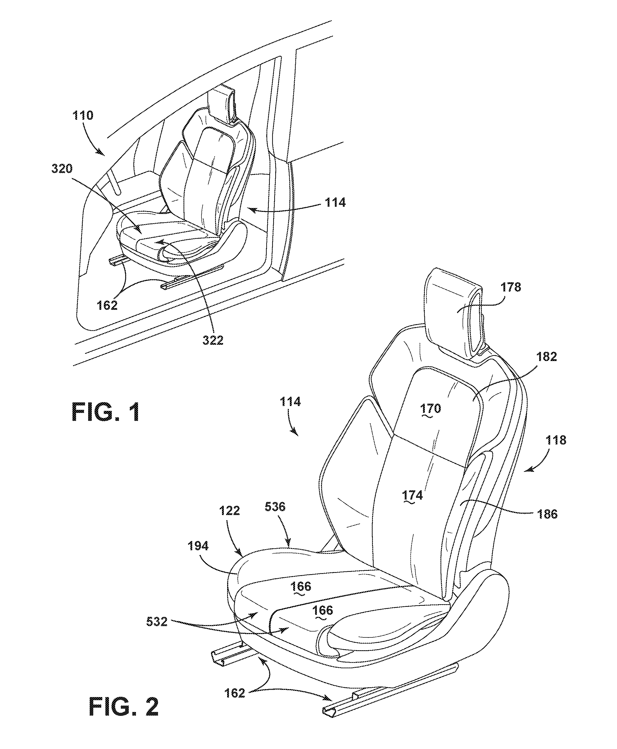
FIG. 1 is a top perspective view of a vehicle seating assembly of the present disclosure disposed in a vehicle;
FIG. 2 is an enlarged top perspective view of the vehicle seating assembly of FIG. 1;
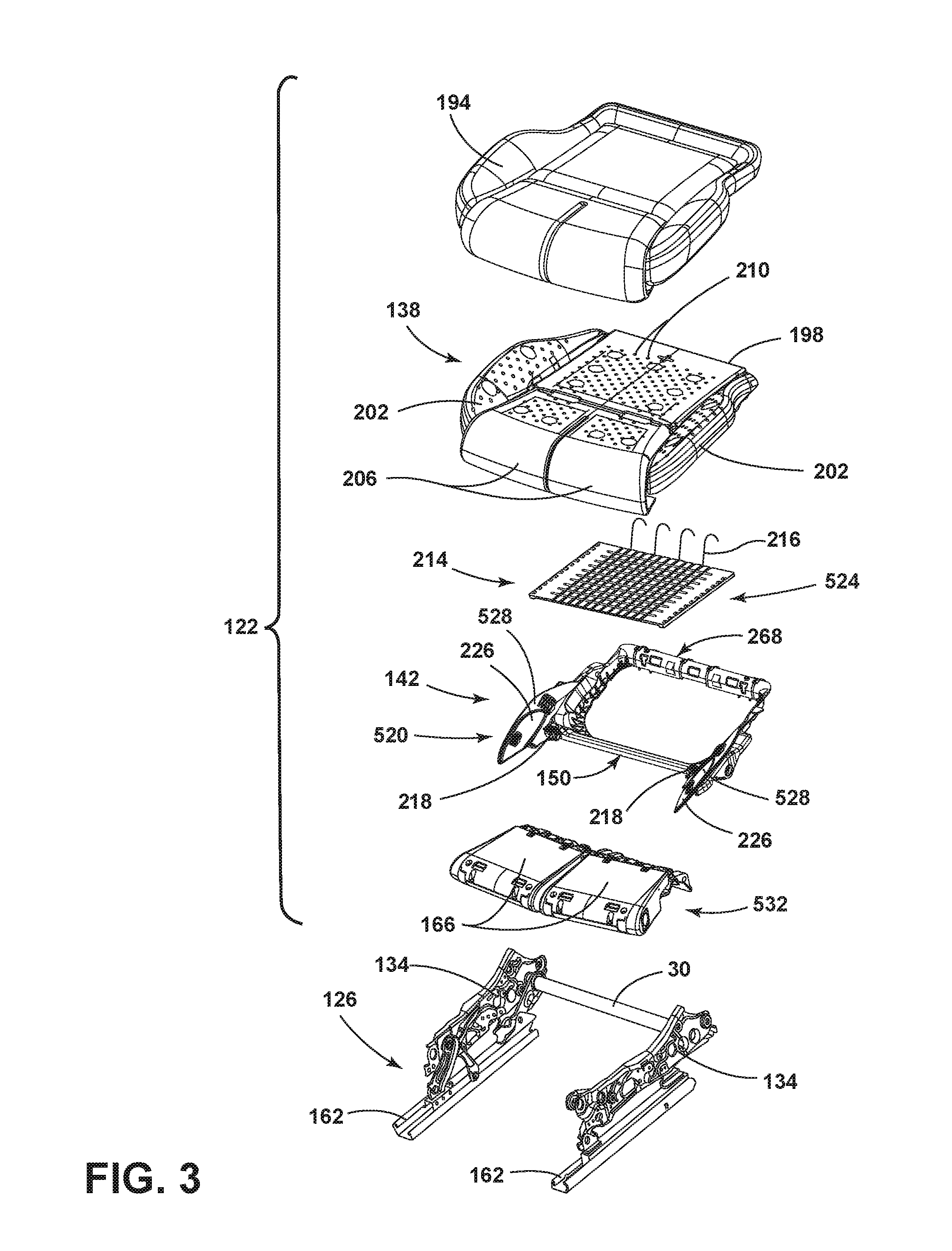
FIG. 3 is a top perspective partial exploded view of a seat of the vehicle seating assembly of the present disclosure;
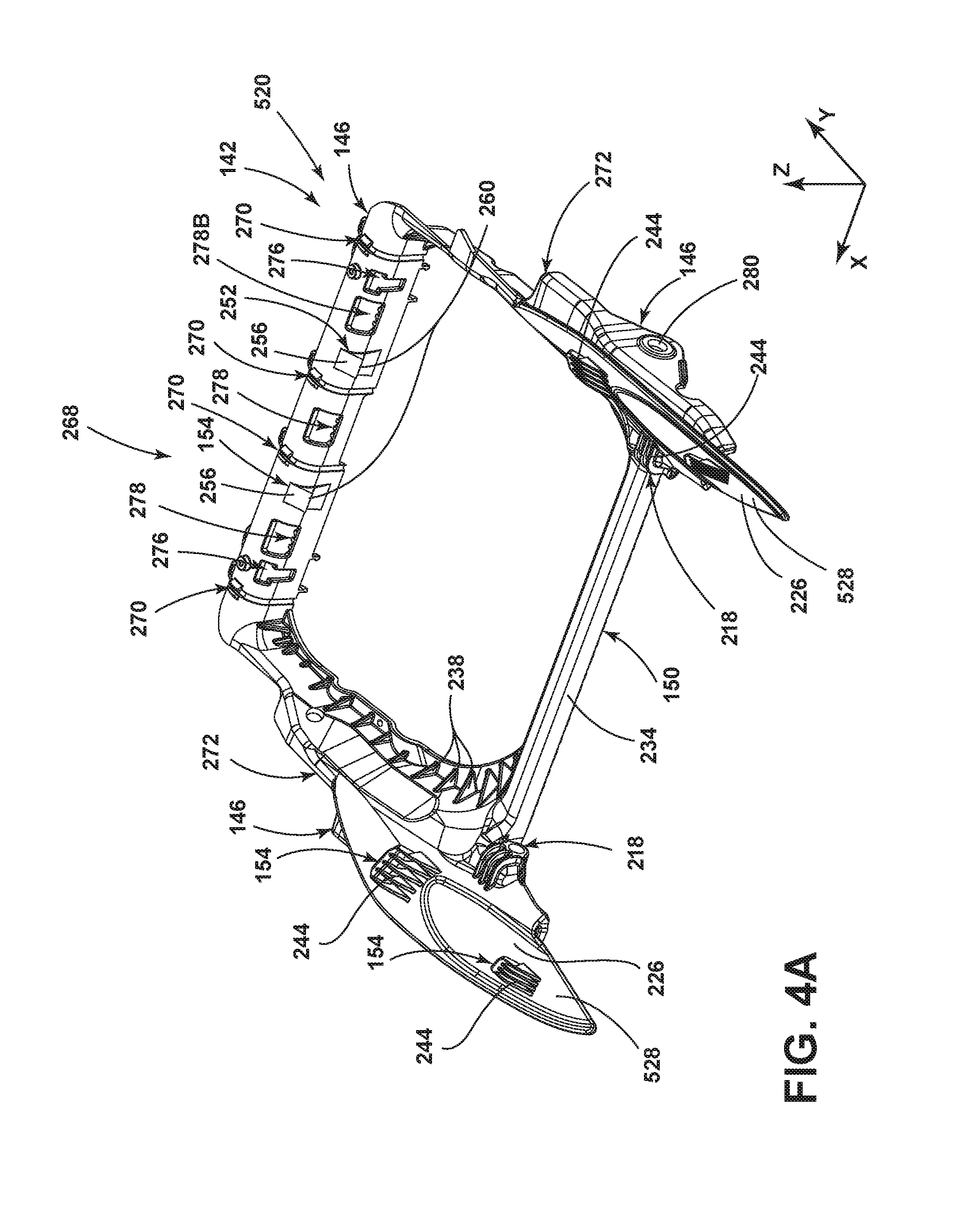
FIG. 4A is a top perspective view of a seat pan of the present disclosure;
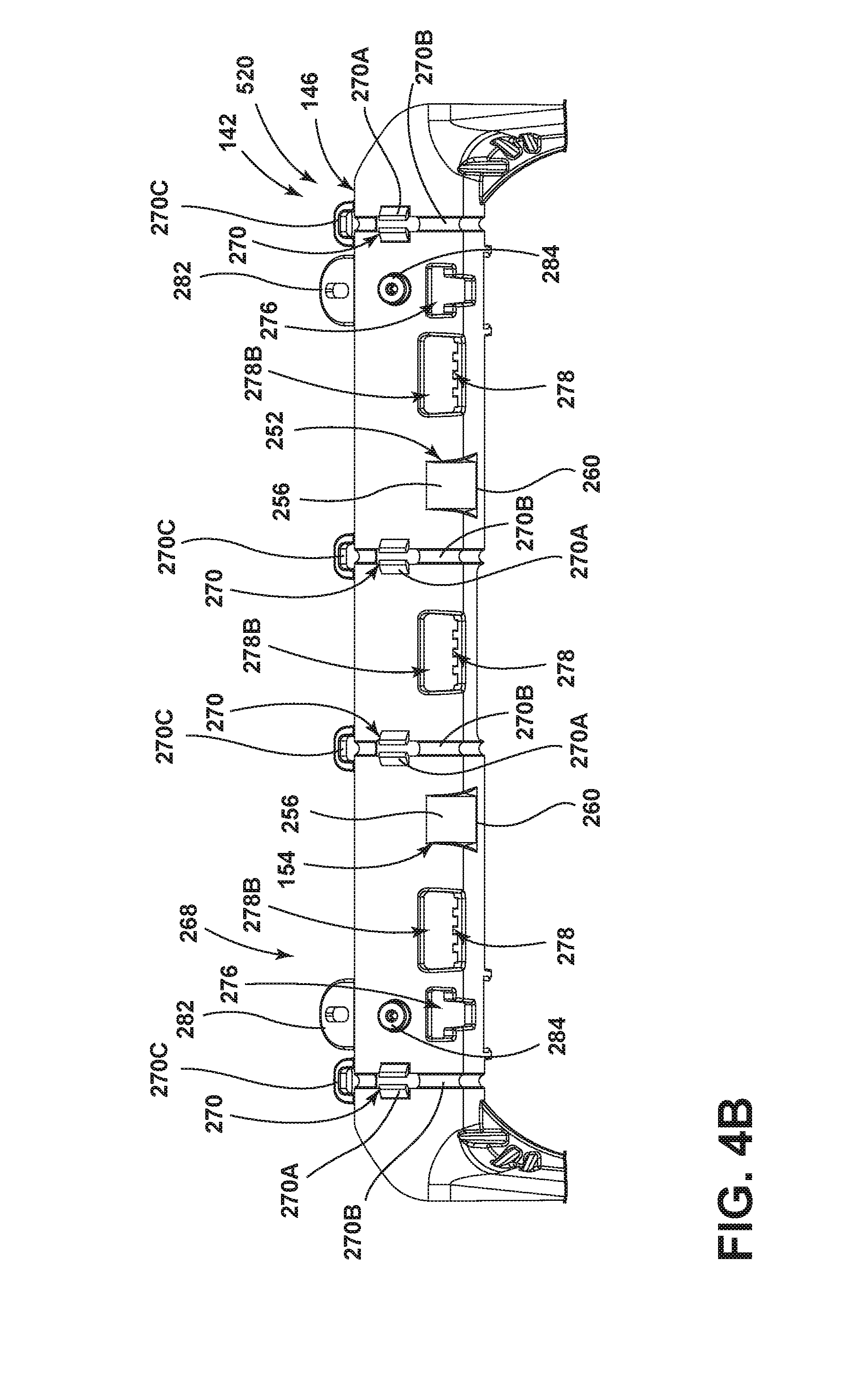
FIG. 4B is an enhanced top view of the seat pan of the present disclosure;
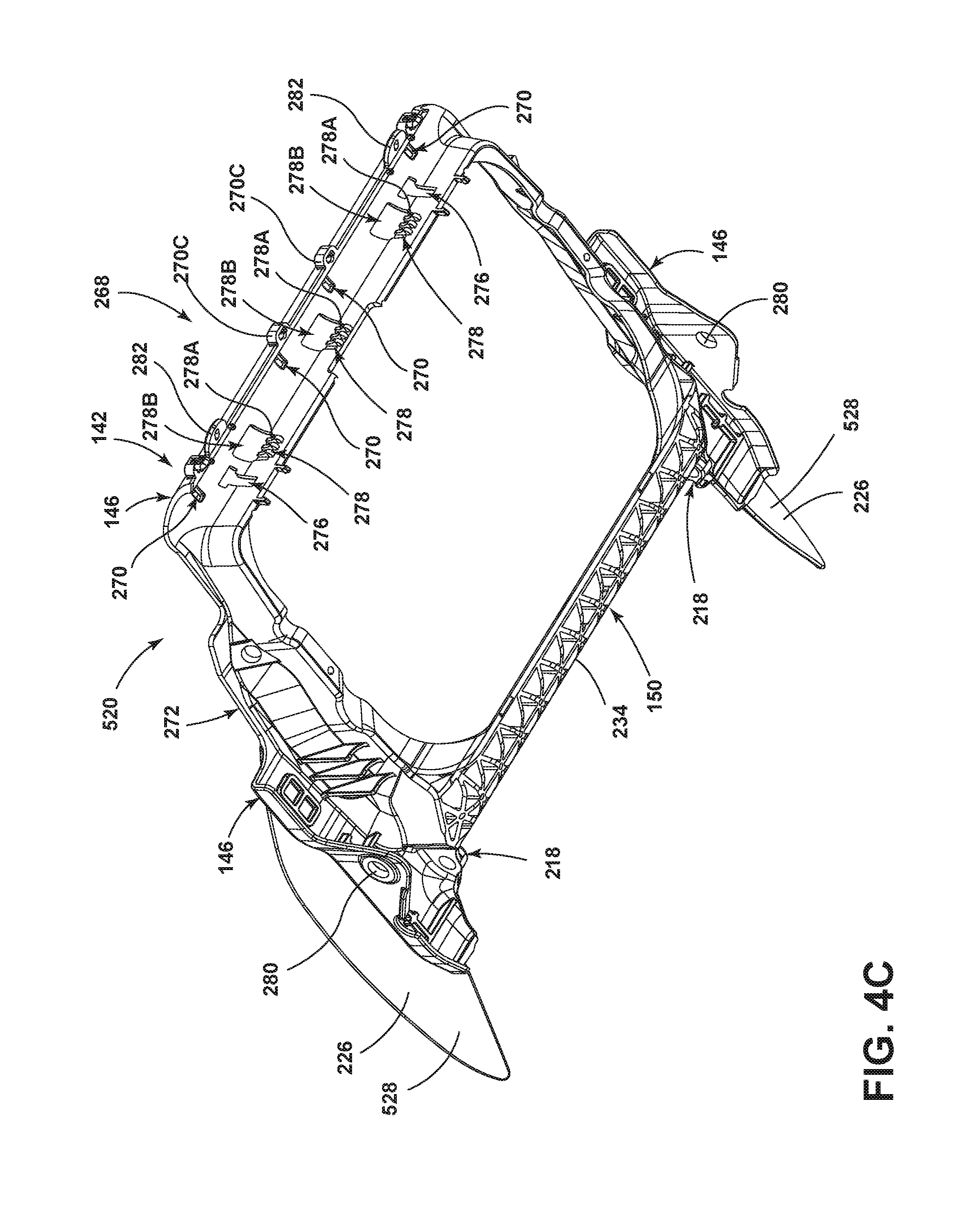
FIG. 4C is a bottom perspective view of the seat pan of the present disclosure;
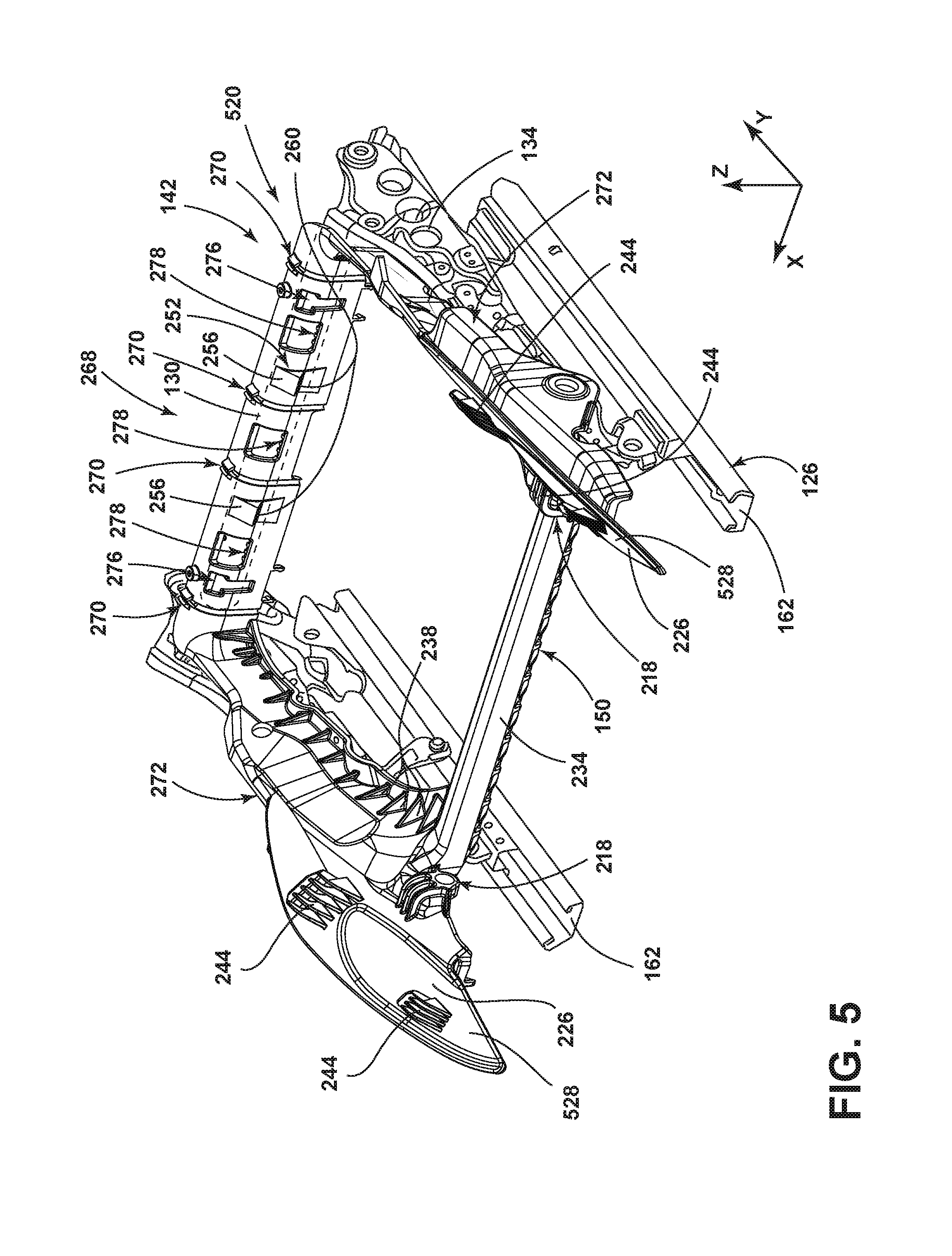
FIG. 5 is a top perspective view of the seat pan of FIG. 4A coupled with a seat frame of the present disclosure;
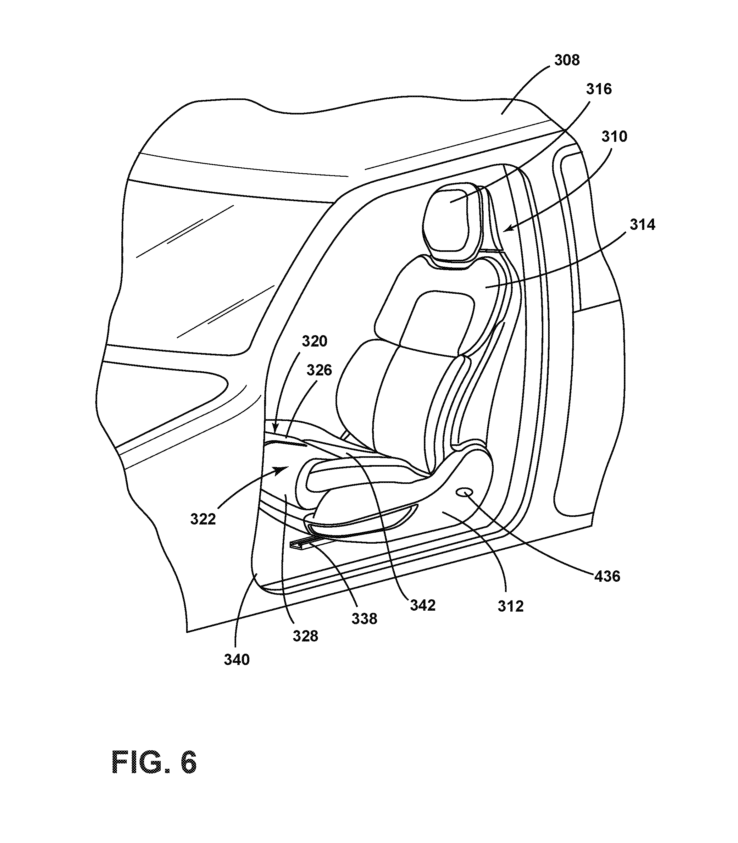
FIG. 6 is a perspective view of one embodiment of a vehicle seating assembly of the present invention disposed in a vehicle;
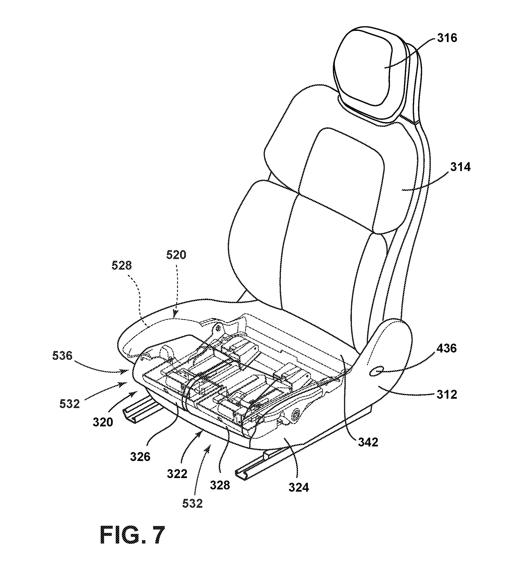
FIG. 7 is a perspective view of the vehicle seating assembly of FIG. 6;
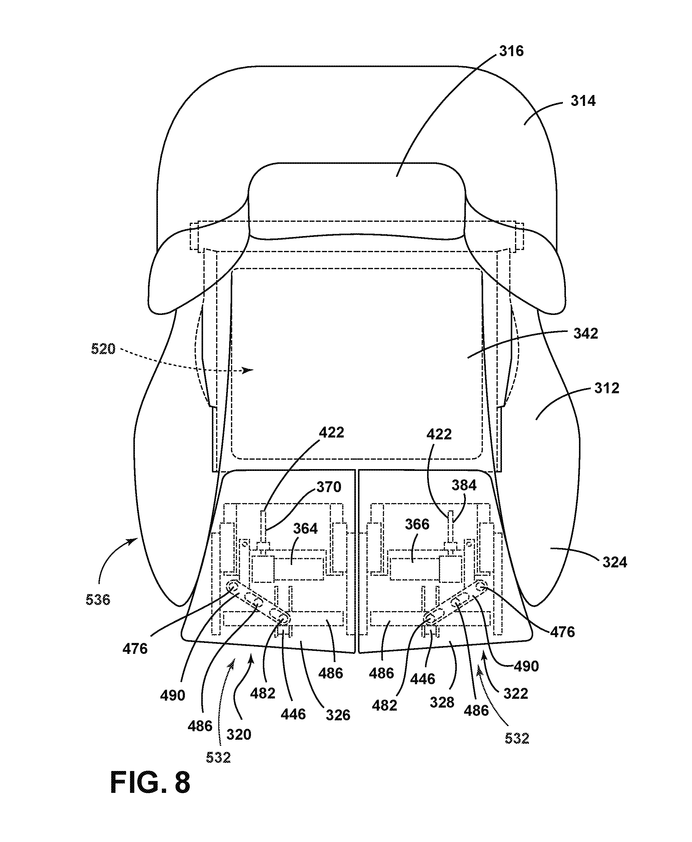
FIG. 8 is a top plan view of the vehicle seating assembly of FIG. 7;
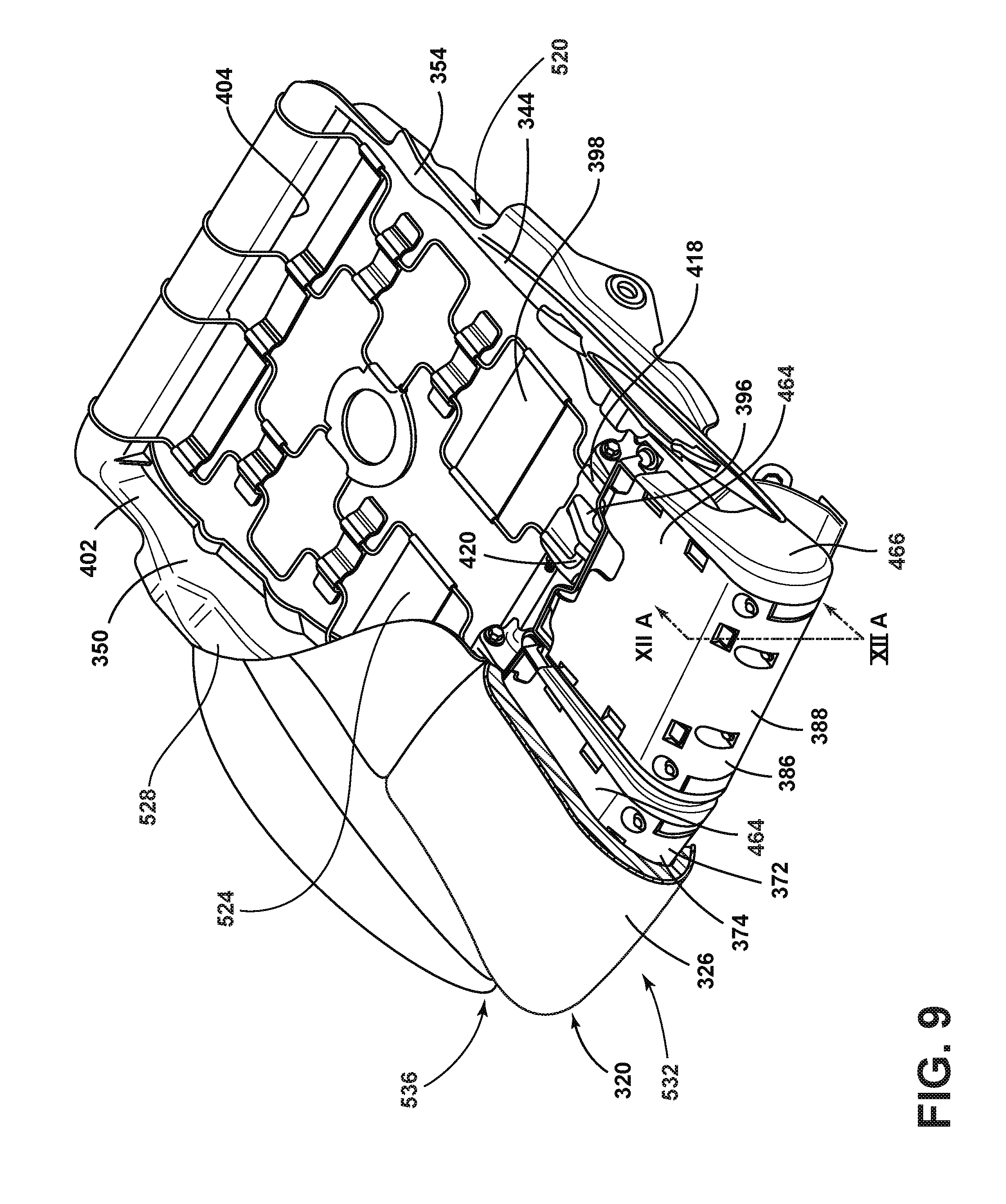
FIG. 9 is a perspective view of the cushion and interface member of the lower seat of the vehicle seating assembly of FIG. 8;
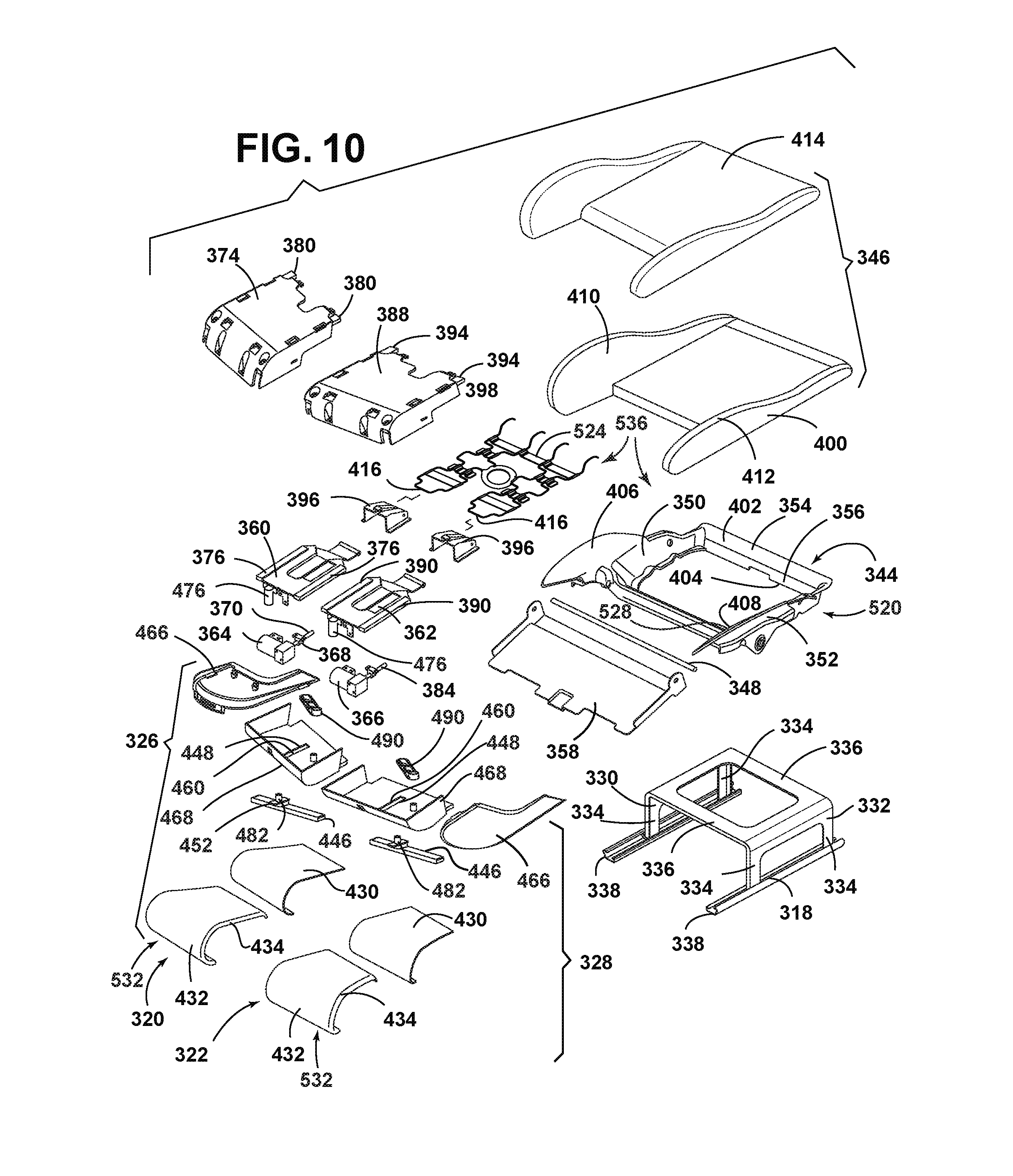
FIG. 10 is a perspective exploded view of the lower seat of the vehicle seating assembly of FIG. 7;
FIG. 11A is a perspective front and side view of the movable housing of the extendable member of the leg supports of the lower seat of the vehicle seating assembly of FIG. 7;
FIG. 11B is a perspective rear and side view of the movable housing of the extendable member of the leg supports of the lower seat of the vehicle seating assembly of FIG. 7;
FIG. 12A is a partial side cross-sectional elevational view taken at line XIIA-XIIA of FIG. 9 illustrating the leg support in a retracted position;
FIG. 12B is a bottom view of the extendable member of the leg support of the lower seat of the vehicle seating assembly of the present invention illustrating the leg support in a retracted position;
FIG. 13A is a partial side cross-sectional elevational view taken at line XIIA-XIIA of FIG. 9 illustrating the leg supports in an extended position;
FIG. 13B is a bottom view of the extendable member of the leg support of the lower seat of the vehicle seating assembly of the present invention illustrating the leg supports in an extended position;
FIG. 14A is a bottom front perspective view of the extendable member of the leg support of the lower seat of the vehicle seating assembly of the present invention with the lower clamshell of the movable housing removed illustrating the leg supports in a retracted position;
FIG. 14B is a bottom rear perspective view of the extendable member of the leg support of the lower seat of the vehicle seating assembly of the present invention with the lower clamshell of the movable housing removed illustrating the leg supports in an extended position; and
FIGS. 15A-C are a series of bottom views of the extendable member of the leg support of the lower seat of the vehicle seating assembly of the present invention illustrating the leg supports in the extended, partially retracted, and fully retracted positions.
DETAILED DESCRIPTION
For purposes of description herein, the terms "upper," "lower," "right," "left," "rear," "front," "vertical," "horizontal," and derivatives thereof shall relate to the concepts as oriented in FIG. 1. However, it is to be understood that the concepts may assume various alternative orientations, except where expressly specified to the contrary. It is also to be understood that the specific devices and processes illustrated in the attached drawings, and described in the following specification are simply exemplary embodiments of the inventive concepts defined in the appended claims. Hence, specific dimensions and other physical characteristics relating to the embodiments disclosed herein are not to be considered as limiting, unless the claims expressly state otherwise.
The present illustrated embodiments reside primarily in combinations of method steps and apparatus components related to a seating assembly. Accordingly, the apparatus components and method steps have been represented, where appropriate, by conventional symbols in the drawings, showing only those specific details that are pertinent to understanding the embodiments of the present disclosure so as not to obscure the disclosure with details that will be readily apparent to those of ordinary skill in the art having the benefit of the description herein. Further, like numerals in the description and drawings represent like elements.
As used herein, the term "and/or," when used in a list of two or more items, means that any one of the listed items can be employed by itself, or any combination of two or more of the listed items, can be employed. For example, if a composition is described as containing components A, B, and/or C, the composition can contain A alone; B alone; C alone; A and B in combination; A and C in combination; B and C in combination; or A, B, and C in combination.
In this document, relational terms, such as first and second, top and bottom, and the like, are used solely to distinguish one entity or action from another entity or action, without necessarily requiring or implying any actual such relationship or order between such entities or actions. The terms "comprises," "comprising," or any other variation thereof, are intended to cover a non-exclusive inclusion, such that a process, method, article, or apparatus that comprises a list of elements does not include only those elements but may include other elements not expressly listed or inherent to such process, method, article, or apparatus. An element proceeded by "comprises . . . a" does not, without more constraints, preclude the existence of additional identical elements in the process, method, article, or apparatus that comprises the element.
Referring to the examples illustrated in FIGS. 1-5, reference numeral 110 generally designates a vehicle which includes a seating assembly 114. The seating assembly 114 includes a seatback 118 and a seat base 122 operably connected to the seatback 118. The seat base 122 includes a seat base frame 126 having a rear tube 130 extending laterally between at least two side members 134. The seat base 122 further includes a seat cushion assembly 138 and a seat pan 142. The seat pan 142 is positioned between the seat cushion assembly 138 and the seat base frame 126. The seat pan 142 has a plurality of recessed features 146 configured to couple over the rear tube 130 and side members 134. The seat pan 142 integrally defines a flexible cross bar 150 extending laterally between the recessed features 146. A plurality of hooks 154 may be integrally defined by the seat pan 142 and may operably couple the seat pan 142 to the seat cushion assembly 138.
Referring now to FIGS. 1-3, the illustrated vehicle seating assembly 114 is configured for use in a vehicle of any type, including, without limitation, cars, vans, trucks, buses, etc. The vehicle seating assembly 114 is suspended on rails 162 that allow movement of the vehicle seating assembly 114 in fore and aft directions within the vehicle 110. In addition, the vehicle seating assembly 114 may include a variety of comfort controls, including, for example, thigh support using independent thigh supports 166, lumbar support, and upper thoracic support. The seatback 118 includes both an upper seatback 170 and a lower seatback 174. The vehicle seating assembly 114 includes a head restraint 178 that is disposed on the upper seatback 170. The head restraint 178 is moveable between forward and rearward positions to accommodate various sized heads of passengers, as well as different heights of passengers. The vehicle seating assembly 114 also includes controls specifically configured to adjust an upper thoracic portion 182 of the upper seatback 170 or a lower thoracic portion 186 of the lower seatback 174.
The seat base 122 includes the seat pan 142 that is operably coupled with the seat base frame 126 and which is configured to support the seat cushion assembly 138 and a cover stock 194 disposed thereon. The seat pan 142 is positioned between the seat base frame 126 and the seat cushion assembly 138. A climate control system may be provided, which can draw air from, or blow air through, the seat cushion assembly 138 and cover stock 194. The seat cushion assembly 138 includes a main cushion 198, seat side bolsters 202, and forward thigh support cushions 206. The thigh support cushions 206 are configured to wrap over the thigh supports 166 to provide comfort while supporting the passenger's thighs. The main cushion 198 and/or seat side bolsters 202 may include a plurality of ventilation holes 210 configured to allow air to pass through the seat base 122. Disposed between the seat pan 142 and the seat cushion assembly 138 is a suspension member 214 configured to provide support to a passenger in the seating assembly 114. The suspension member 214 includes a plurality of suspension hooks 216 positioned at a rear of the suspension member 214.
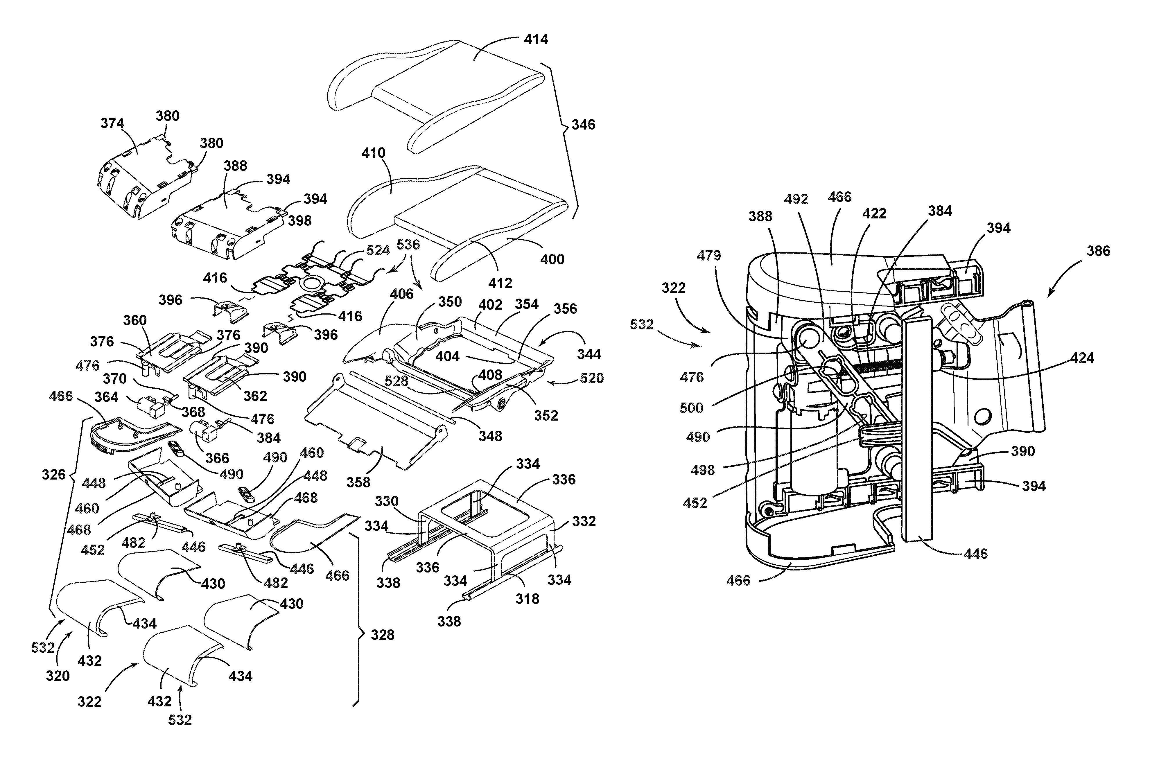
With further reference to FIG. 3, the vehicle seating assembly 114 includes the seat base 122. The seatback 118 (FIG. 2) is operably coupled to a rear of the seat base 122. Each of the first and second independently moveable thigh supports 166 are independently laterally translatable forward and rearward relative to the seat base 122. A spring assembly may be used to urge each thigh support 166 to a fully forward lateral position. Each of the first and second independently moveable thigh supports 166 are rotatable relative to the seat base 122. The thigh supports 166 may be coupled to the seat pan 142 at thigh attachment points 218 positioned on a vehicle forward location of the seat pan 142. The thigh attachment points 218 may be integrally defined by the seat pan 142 or may be coupled thereto. As noted above, the thigh supports 166 are configured to rotate upward and downward relative to the seat base 122 between raised and lowered positions, and are also configured to translate laterally between extended and retracted positions relative to the seat base 122. The moveable thigh supports 166 are independent such that one thigh support 166 may be at the raised position, while the other thigh support 166 may be at the lowered position, or at any position in between the raised and lowered positions.
Referring now to FIG. 4A, the seat pan 142 may be formed of a metal, plastic, or composite material. In composite material examples of the seat pan 142, the seat pan 142 may be formed of a fiber filler and resin combination. The fiber filler volume fraction within the resin may be between about 1% and about 60%, or between about 15% and about 40%, or between about 30% and about 40%. In a specific example, the fiber filler volume fraction within the seat pan 142 may be about 35%. The fibers may be composed of materials including carbons, aramids, aluminum metals, aluminum oxides, steels, borons, silicas, silicon carbides, silicon nitrides, ultra-high-molecular-weight polyethylenes, A-glasses, E-glasses, E-CR-glasses, C-glasses, D-glasses, R-glasses, and S-glasses. The fibers may be continuous or chopped to a particular length. The length of the chopped fibers can be between about 1 mm and about 20 mm, or between about 3 mm and about 11 mm, or between about 5 mm and about 7 mm. Typically, the fibers are randomly oriented in the resins within the seat pan 142. However, the fibers may also be substantially aligned directionally in areas of the seat pan 142 subject to high directional stresses or areas of anticipated stress (e.g., connections or transitions between parts of the seat pan 142). The seat pan 142 may incorporate one or more preformed fiber mats which may include woven or non-woven fibers that are held together using the same or different resins as employed in the seat pan 142. The resin employed in the seat pan 142 may include a nylon, a polypropylene, an epoxy, a polyester, a vinyl ester, a polyetheretherketone, a poly(phenylene sulfide), a polyetherimide, a polycarbonate, a silicone, a polyimide, a poly(ether sulfone), a melamine-formaldehyde, a phenol-formaldehyde, and a polybenzimidazole, or combinations thereof. The use of a composite material such as a fiber filled resin may allow the seat pan 142 to be formed via injection molding, thermoforming, and other processes for forming a polymeric member. The use of a fiber composite material for the seat pan 142 may allow for increased durability and fatigue loading of the seat pan 142.
In the depicted example, the seat pan 142 includes side bolsters 226. The side bolsters 226 may be integrally formed with the seat pan 142 or may be attached thereto. The side bolsters 226 are configured to support and flex under stress to provide resiliency to the seat side bolsters 202 (FIG. 3). Additionally, integrally forming the side bolsters 226 with the seat pan 142 increases the structural support for the passenger during ingress/egress from the seating assembly 114, as well as during jounce and abuse loading circumstances. The side bolsters 226 are configured to deflect or flex in an X-direction, a Y-direction, and/or a Z-direction. The side bolsters 226 may deflect greater than about 10 mm, 20 mm, 30 mm, 40 mm, 50 mm, 60 mm, 70 mm, 80 mm, 90 mm, or greater than about 100 mm in any or all of the X-, Y-, or Z-directions without breaking or breakage during a stress or loading event (e.g., front end collision of the vehicle 110 or movement of a passenger within the seating assembly 114 of FIG. 1). Extending across the seat pan 142 and between the recessed features 146 is the cross bar 150. The cross bar 150 may include a wall 234 and a plurality of ribs 238. The plurality of ribs 238 extend in a direction perpendicular to that of the wall 234. The positioning of the ribs 238 along the wall 234 provides a stress relief design for the cross bar 150 such that it may flex or deflect. The cross bar 150 may take a variety of cross-sectional shapes including square, rectangular, circular, ellipsoid, or other shapes configured to define the wall 234. The cross bar 150 is configured to deflect or flex in the X-direction, the Y-direction, and the Z-direction. The cross bar 150 may deflect greater than about 10 mm, 20 mm, 30 mm, 40 mm, 50 mm, 60 mm, 70 mm, 80 mm, 90 mm, or greater than about 100 mm, in any or all of the X-, Y-, or Z-directions without breaking or breakage during a stress or loading event (e.g., a front end collision) under temperature conditions as high as 70.degree. C. and humidity as high as 60%. In some examples, the temperature and/or humidity of the environment surrounding the seat pan 142 may affect (e.g., increase) the deflection amount of the cross bar 150. By configuring the cross bar 150 to be flexible, it allows the cross bar 150 to deflect during an impact or sudden deceleration event for the vehicle 110. During forward impact or sudden deceleration of the vehicle 110, a passenger of the seating assembly 114 may be forced into the seat base 122 (FIG. 1) due to continued forward motion of the passenger relative to the seating assembly 114. Movement of the passenger into the seat base 122 may cause submarining, or movement of the passenger below a safety belt of the seating assembly, to occur. By configuring the cross bar 150 to flex and deflect under stress, but not break, a passenger of the seating assembly 114 may be decelerated safely such that submarining is minimized or eliminated.
As explained above, the seat pan 142 defines a plurality of hooks 154 disposed about the seat pan 142. In the depicted example, each of the side bolsters 226 integrally define a pair of rearward hooks 244. In other examples, the rearward hooks 244 may be otherwise joined to the side bolsters 226. The rearward hooks 244 are configured to face in a vehicle rearward direction and are configured to engage the seat cushion assembly 138 of FIG. 3 and retain it against the seat pan 142. The seat cushion assembly 138 may define a plurality of recesses or retention features on an underside of the main cushion 198 and seat side bolsters 202 configured to engage and retain the rearward hooks 244. Additionally, the rearward facing nature of the rearward hooks 244 resists the motion of the seat cushion assembly 138 in a vehicle forward direction during an impact or sudden deceleration event. In some examples, the rearward hooks 244 may include a snap feature such that the seat cushion assembly 138 is locked to the seat pan 142. In addition to the rearward hooks 244, the plurality of hooks 154 also include at least one downward hook 252. In the depicted example, the seat pan 142 integrally defines two downward hooks 252. The downward hooks 252 include an angled surface 256 and a retention lip 260. The downward hooks 252 are configured to retain the seat cushion assembly 138 downward against the seat pan 142. During an exemplary assembly method of the seat cushion assembly 138 to the seat pan 142, the seat cushion assembly 138 is engaged (e.g., snapped) to the rearward hooks 244 by applying vehicle forward motion to the seat cushion assembly 138. Once the seat cushion assembly 138 is attached to the rearward hooks 244, the rear of the seat cushion assembly 138 is forced downward under the downward hooks 252. During the downward motion of the seat cushion assembly 138, the seat cushion assembly 138 contacts and slides along the angled surface 256. The seat cushion assembly 138 is then slid under the retention lip 260. The retention lip 260 extends over the seat cushion assembly 138 such that the seat cushion assembly 138 is rotationally and vertically locked under the downward hooks 252.
Referring now to FIGS. 4A-4C and 5, in addition to the plurality of hooks 154 and the cross bar 150, the seat pan 142 additionally defines the plurality of recessed features 146. The plurality of recessed features 146 include a rear recessed feature 268 and side recessed features 272. The rear recessed feature 268 extends the width of the seat pan 142 and has a generally curved structure. The curved structure of the rear recessed feature 268 is configured to couple with the rear tube 130 of the seat base frame 126. The rear recessed feature 268 is configured to partially surround, or nest, over the rear tube 130 such that the rear tube 130 supports the seat pan 142 through the rear recessed feature 268. The rear tube 130 may be any lateral cross member that is hollow or solid, and may take a variety of cross-sectional shapes including rectangular, square, circular, ellipsoid or others configured to provide structural rigidity to the seat base frame 126. In examples where the rear tube 130 is a shape other than circular, the rear recessed feature 268 may be complimentarily shaped to couple or nest over the rear tube 130. As depicted, the downward hooks 252 are defined on the rear recessed feature 268. Additionally, the rear recessed feature 268 may define one or more attachment apertures 276 which may be utilized with a fastener for securing the rear recessed feature 268 to the rear tube 130. The rear recessed feature 268 defines a plurality of locking features 278. The locking features 278, in the depicted example, include a plurality of teeth. The locking features 278 protrude into the recessed portion of the rear recessed feature 268 and are configured to engage the rear tube 130 (FIG. 3). The locking features 278 define upwardly curved surfaces 278a configured to mate with the rear tube 130. The upwardly curved surfaces 278a extend partially under the rear tube 130, such that the rear tube 130 may be snap fit into the rear recessed feature 268 and the seat pan 142 is secured to the seat base frame 126. Additionally or alternatively, the locking features 278 may be used to help locate the seat pan 142 onto the correct location on the rear tube 130. Further, the rear recessed feature 268 defines a plurality of locking apertures 278B which may allow one or more fasteners to fasten the seat pan 142 to the rear tube 130. In another example, a portion of the rear tube 130 may extend through the locking apertures 278B.
Further, the rear recessed feature 268 may define one or more suspension attachment features 270. The suspension attachment features 270 include a suspension clip 270A, a suspension channel 270B, and a suspension retainer 270C. The suspension attachment features 270 are configured to engage the suspension hooks 216. The suspension clips 270A may be snap features, clips, hook and loop attachments or other features configured to grip the suspension hooks 216 to provide retention between the suspension member 214 and the seat pan 142. The suspension channels 270B are sized to accept the suspension hooks 216 to create a low profile appearance. The suspension hooks 216 wrap over the rear recessed feature 268 through the suspension channel 270B and suspension clips 270A, and engage the suspension retainers 270C. The suspension retainers 270C retain the ends of the suspension hooks 216 in place. Positioned proximate the suspension retainers 270C are retaining flanges 282. The retaining flanges 282 are configured to accept a fastener to further secure the seat pan 142 to the seat base frame 126 or other seating relating structures. Positioned on top of the rear recessed feature 268 may be a plurality of fasteners 284.
The side recessed features 272 are positioned proximate the side bolsters 226 along sides of the seat pan 142. The side recessed features 272 are shaped complimentary to that of the side members 134 and have sufficient width such that the side recessed features 272 may couple over, or nest on, the side members 134. The side recessed features 272 may define attachment points 280 through which a bolt or other fastener may be used to secure the seat pan 142 to the side members 134 of the seat base frame 126. Cooperation of the bolts or fasteners through the attachment points 280 and the attachment apertures 276 aid in securing the seat pan 142 to the seat base frame 126.
Use of the recessed features 146 may allow for easy assembly of the seat pan 142 to the seat base frame 126. In an exemplary assembly method, the seat pan 142 is positioned over the seat base frame 126 such that the recessed features 146 are aligned with the side members 134 and the rear tube 130. The seat pan 142 is then placed on the seat base frame 126 such that the recessed features 146 are nested on the side members 134 and the rear tube 130. Finally, fasteners may be secured through the attachment points 280 and the attachment apertures 276 to secure the seat pan 142 to the seat base frame 126.
Use of the present disclosure may offer several advantages. For example, use of the present disclosure may allow the seating assembly 114 to meet various testing standards including static strength, dynamic strength, vibration and durability/fatigue, dynamic pulses, safety crashes, passenger jounce as well as ingress/egress, squeak/rattle, abuse loading, thigh support, life cycle and others. Additionally, use of the present disclosure may increase the modularity of the seating assembly 114 which may decrease costs associated with shipping, overhead, and assembly while correspondingly increasing the customization of the seating assembly 114. Further, the present disclosure may offer a weight neutral or weight savings alternative as compared to traditional seating assemblies while increasing structural performance. Finally, use of the composite seat pan 142 structure allows for the integral molding of connection and attachment points for electrical, mechanical and/or pneumatic systems which may save on assembly time, cost, packaging space, and weight, as well as manufacturing cost.
Turning now to FIGS. 6-15C, additional or alternative features and concepts of the present disclosure are depicted. It will be understood by one of ordinary skill in the art that the features depicted and discussed in FIGS. 1-5 can be similar or identical to the features depicted and discussed below for FIGS. 6-15C.
Referring to FIGS. 6 and 7, reference numeral 310 generally designates a vehicle seating assembly for a vehicle 308 having a lower seat 312 and an upwardly extending seatback 314. The seatback 314 supports a headrest 316 thereon. The seatback 314 is pivotally coupled with the lower seat 312, such that the seatback 314 can be moved between upright and inclined positions. The headrest 316 is operably, and preferably slidably, coupled with the seatback 314 and also positioned in a variety of positions relative to the seatback 314 to support the head and neck of a driver or a passenger.
Referring again to FIGS. 6 and 7, the lower seat 312 includes a seat frame 318 to which a first and second leg support 320, 322 are pivotally coupled with a forward portion 324 of the lower seat 312. The first leg support 320 is preferably operable between raised and lowered positions. A first extendable member 326 is disposed beneath the first leg support 320 and is operable between an extended and a retracted position. The second leg support 322 is adjacent to and independent of the first leg support 320 and is likewise preferably pivotally coupled with the forward portion 324 of the seat frame 318, such that the second leg support 322 is operable between raised and lowered positions. A second extendable member 328 is likewise disposed beneath the second leg support 322 and is operable between extended and retracted positions.
The seat frame 318 includes first and second side members 330, 332 (FIG. 9) supported on legs 334 (FIG. 10). Laterally extending frame members 336 (FIG. 10) extend between the first and second side members 330, 332. The legs 334 are operably coupled with seat track slide assemblies 338 that are secured to a floor 340 of the vehicle 308.
Referring now to FIGS. 8 and 9, the vehicle seating assembly 310 is generally configured to apply selective support to the underside of the legs of the driver or passenger. Specifically, as shown in FIG. 8, each leg of the driver or passenger can be independently supported by the first and second leg supports 320, 322. The first and second leg supports 320, 322 are movable between raised and lowered positions, as well as between extended and retracted positions to modify an effective seating area 342 of the vehicle seating assembly 310 and optimize accommodation of the size, shape, posture, and sitting positions of the driver or passenger.
As further shown in FIG. 8, the first extendable member 326 and the second extendable member 328 each extends forwardly from the seatback 314. The first extendable member 326 and the second extendable member 328 preferably extend forward at an angle laterally from a centerline and forwardly from an H-point to provide better leg support and comfort on the outside of the occupant's thighs in a position that naturally conforms to the natural leg-splay of a human occupant. This leg-splay angle is maintained in both the extended and retracted positions for optimized comfort in all positions. The angle is preferably between 5 and 10 degrees, and more preferably about 5 degrees, from the seat H-point along the centerline C of the lower seat 312. The split between the first extendable member 326 and the second extendable member 328 at such an angle .alpha. provides improved comfort that reduces muscle strain and improves leg and thigh support.
Referring now to FIG. 10, the vehicle seating assembly 310 includes an interface member 344 that is supported over the seat frame 318. The interface member 344 is positioned between the seat frame 318 and the upper portion 346 of the lower seat 312. The interface member 344 is disposed behind the first and second leg supports 320, 322 and in front of the seatback 314. The interface member 344 includes a pivot rod 348 that extends between first and second sides 350, 352 of the interface member 344. Additionally, a rear portion 354 of the interface member 344 includes a frame engagement component 356 that secures the interface member 344 to the seat frame 318. The pivot rod 348 is coupled with a pivotable base plate 358 situated beneath the first and second extendable members 326, 328.
As shown in FIG. 10, first and second support bases 360, 362 support the first and second leg supports 320, 322, respectively. The first and second support bases 360, 362 are operably coupled with first and second motors 364, 366, respectively. The first motor 364 is operably coupled with a drive shaft 370. The drive shaft 370 is capable of laterally translating a first support body 372 that includes a first movable housing 374 that is slidingly engaged by a pair of rails 376 mounted on each lateral side of the support base 360. A pair of slide tracks 380 mounted on the lateral side of the interior of the first movable housing 374 engages the rails 376 to allow the first movable housing 374 to slide forward and backwards relative to the first support base 360, as will be further discussed below, and between extended and retracted positions. Similarly, the second motor 366 is operably coupled with a drive shaft 384. The drive shaft 384 is capable of laterally translating a second support body 386 of the second leg support 322 between extended and retracted positions. The second support body 386 also includes a second movable housing 388 that is slidingly engaged by a pair of rails 390 mounted on each lateral side of the second support base 362. A pair of slide tracks 394 mounted on the lateral sides of the interior of the second movable housing 388 (see FIG. 11B) engages the rails 390 to allow the second movable housing 388 to slide forward and backwards relative to the second support base 362 between extended and retracted positions (see FIGS. 14A and 14B).
Referring again to FIG. 10, the interface member 344 includes suspension assembly 398 that supports a seat cushion 400. Preferably, the interface member 344 has a shape that largely complements the shape of the seat cushion 400. Specifically, the interface member 344 includes a body 402 defining an aperture 404 configured to receive the suspension assembly 398, which supports the seat cushion 400. At the same time, first and second wings 406, 408 extend from the body 402 and are configured to support first and second side cushions 410, 412 of the seat cushion 400. The seat cushion 400 is supported above the suspension assembly 398 and is protected by a cushion cover stock 414. It is anticipated that the cushion cover stock 414 could be any of a number of materials, including traditional fabrics, as well as leathers, vinyl, and fabric material. The laterally extending pivotable base plate 358 is positioned below the first and second leg supports 320, 322 and is coupled to the seat frame 318. The laterally extending pivotable base plate 358 assists in guiding the first and second leg supports 320, 322 between the various positions, and, at the same time, provides additional rigidity to the seat frame 318 of the vehicle seating assembly 310.
Referring now to FIGS. 11 and 12, the first and second leg supports 320, 322 will be discussed in further detail. The first and second leg supports 320, 322 are configured to engage the interface member 344 of the vehicle seating assembly 310. Specifically, the first and second support bases 360, 362 are pivotally coupled via bracket 396 with and pivot about the forward elements 418 of the suspension assembly 398 at pivot point 420, as shown in FIGS. 9 and 10. The first and second support bases 360, 362 are thus rotatably and fixedly coupled with the interface member 344 of the vehicle seating assembly 310.
In a preferred embodiment, the first and second support bases 360, 362 are operable between the raised and lowered positions about the pivot point 420. Preferably, each of the first and second support bases 360, 362 are biased to the raised position. It is generally contemplated that the support body 372 of the first leg support 320 and the support body 386 of the second leg support 322 may be movable to the raised position and the lowered position via an actuation assembly operably coupled with a motor (not shown). Alternatively, adjustment of the first and second leg supports 320, 322 may be made manually via a gear system, as understood by one having ordinary skill in the art.
In order to effect fore and aft motion of the first and second leg supports 320, 322, the first and second electric motors 364, 366 of the first and second leg supports 320, 322, respectively, are positioned on and affixed to the first and second support bases 360, 362. The first and second motors 364, 366 are operably coupled with the drive shafts 370, 384, respectively. Each drive shaft 370, 384 includes a screw gear 422 disposed thereon that engages a gear nut 424 disposed on and affixed to the interior of the first and second movable housing 374, 388. The screw gear 422 is thus mounted to the first and second support bases 360, 362 and is rotatably engaged with the gear nut 424 disposed on each of the first and second movable housings 374, 388, which allows for linear translation of the first and second leg supports 320, 322 between the extended and retracted positions, as discussed below.
Referring again to FIGS. 12 and 13, each of the first and second leg supports 320, 322 includes a slide assembly 426 comprising the aforementioned rails 376, 390 mounted on the first and second support bases 360, 362 and the slide tracks 380, 394 mounted within the first and second movable housings 374, 388. The tracks 380, 394 of the support bodies 372, 386 of the first and second leg supports 320, 322 are configured to receive the rails 376, 390 mounted on the first and second support bases 360, 362. The support bodies 372, 386 are thereby configured to engage the slide assembly 426.
The gear nut 424, as noted above, is mounted to an interior surface of each of the first and second movable housings 374, 388 (as shown in FIGS. 14A and 14B) and is linearly translatable via the screw gear 422 between fore and aft positions. As described in further detail below, when the gear nut 424 is in the aft position, the relevant leg support 320 or 322 is in the retracted position. Similarly, when the gear nut 424 is in the forward position, the relevant leg support 320 or 322 is in the extended position. The first and second extendable members 326, 328 are thereby operatively coupled with the forward portion 324 of the lower seat 312.
Referring again to FIGS. 12 and 13, a protective wrap 430 is disposed about an upper, lower, and forward portion of each support body 372, 386. The protective wrap 430 is itself covered by a leg support trim cover stock 432 over a cushion layer 434, the cushion layer 434 being disposed between the trim cover stock 432 and protective wrap 430. The leg support cover stock 432 and the cushion layer 434 thereby conceal the protective wrap 430.
Referring now to FIGS. 12A and 12B, the vehicle seating assembly 310 is illustrated with the second leg support 322 moved to an initial position. In the initial position, the second leg support 322 is in the retracted position. In this initial position, the effective seating area 342 of the lower seat 312 has not been enlarged. Accordingly, the effective seating area 342 is generally configured to support a driver or passenger that is smaller in stature. In the event the driver or passenger has a larger stature and wishes to change the effective seating area 342 of the vehicle seating assembly 310, then the first and second leg supports 320, 322 can be extended independently, preferably at an optimized lateral angle .alpha. of between 5 to 10 degrees relative the centerline C.
Referring now to FIGS. 13A and 13B, in the illustrated embodiment, the second leg support 322 has been translated to the extended position. To move the second leg support 322 to the extended position, the driver or passenger would simply engage a toggle switch 436 on the lower seat 312 that is operably coupled to the second motor 366. The second motor 366 then activates, which turns the drive shaft 384 that is coupled with the screw gear 422. Notwithstanding the foregoing, it is contemplated that the benefits of the present disclosure may also be obtained in a manual system that does not employ motor 364, 366, but rather relies upon manual rotational input, as is known in the art.
As shown in FIGS. 14A and 14B, as the screw gear 422 rotates, the gear nut 424 attached to the second movable housing 388 begins to move relative to the screw gear 422. Specifically, when the second motor 366 operates in a first direction, the screw gear 422 rotates such that threads of the screw gear 422 push internal threads of the gear nut 424, which translates the gear nut 424 and the second leg support 322 away from the interface member 344 (corresponding to the extended position of the second leg support 322). When the second motor 366 operates in a second direction, the screw gear 422 turns in a second direction opposite the first direction, such that the gear nut 424 is drawn toward the interface member 344 (corresponding with the retracted position of the second leg support 322).
As the screw gear 422 rotates in the first direction, the support body 386 of the second leg support 322 is pushed outwardly away from the interface member 344. At the same time, the second support base 362 maintains position and does not move. As the gear nut 424 is rigidly mounted to the interior surface 488 of the second movable housing 388, the second leg support 322 is moved forward relative the first support base 360. Thus, the interaction of the rail 390 with the tracks 394 allows for the second leg support 322 to extend relative to the first leg support 320.
Although the electrical motor 366 is preferably disclosed as being mounted on the second support base 362 and the driven gear nut 424 is mounted on the interior surface of the second movable housing 388, the components can be reversed. That is, the motor 366 may be mounted on the second movable housing 388, and the driven gear nut 424 may be mounted on the second support base 362. In the event the driver or passenger also wanted the first leg support 320 to be moved to the extended position, the driver or passenger could engage in the same behavior to actuate the first motor 364, which would then force the support body 372 of the first leg support 320 outward in a similar fashion to that described above with reference to the second leg support 322.
A beneficial feature of the present disclosure is that as the first and second movable housing 374, 388 extend forwardly beneath the protective wrap 430, cushion layer 434, and cover stock 432 of the leg supports 320, 322, the cover stock 432, cushion layer 434, and protective wrap 430 immediately beneath the occupant's thigh does not move. The cover stock 432 and cushion cover stock 414 also form a substantially smooth surface that does not collect debris throughout the motion of the extendable members 326, 328. That is, the cover stock 432 for the leg supports 320, 322, which forms a substantially rectangular panel, is at least partially disposed above an upper surface 438 of each of the first and second movable housings 374, 388 and is at least partially disposed below each of the first and second movable housings 374, 388.
Each cover stock 432 for the leg supports 320, 322 has a first fixed upper edge 440 and a second movable lower edge 442. The first fixed upper edge 440 of the cover stock 432 is fixedly attached to the cushion cover stock 414 over the cushion to form a continuous uninterrupted lateral seam or bite 444 between the first fixed upper edge 440 of the cover stock 432 and the cushion cover stock 414. The second movable lower edge 442 of the cover stock 432, located beneath each of the first and second leg supports 320, 322, is fixedly attached to an attachment member 446, which operates to maintain tension in the cover stock 432 of the leg supports 320, 322 during the extension and retraction operation.
The attachment member 446 is part of an articulating system that uniquely maintains the aforementioned tension in the cover stock 432 of the leg supports 320, 322. Each of the movable housings 374, 388 is provided with an articulating mechanical linkage system operatively coupling the movable housing 374, 388 to the second movable lower edge 442 of the trim cover stock 432 to maintain tension on the trim cover stock 432 as either of the first and second extendable members 326, 328 is operated between the extended and retracted positions. Each of the movable housings 374, 388 of the first and second extendable members 326, 328 further includes an integrated track 448 disposed on a lower surface 450 of the movable housing 374, 388, and a trim payout slider 452 operably coupled with the integrated track 448 and adapted for fore and aft motion therein. The trim payout attachment member 446 is also operably coupled with the trim payout slider 452.
As the integrated track 448 is disposed on the lower surface 450 of the movable housing 374, 388, the trim payout slider 452 is effectively concealed from view and is relatively free from interference in its operation. The trim payout slider 452 is operably coupled with the integrated track 448 and adapted for fore and aft motion therein, and the trim payout attachment member 446 is operably coupled with the second movable lower edge 442 of the trim cover stock 432 and is operably coupled with the trim payout slider 452. The trim payout slider 452 is thus operably coupled with the second movable lower edge 442 of the cover stock 432 via the trim payout attachment member 446, and is thus capable of moving the second movable lower edge 442 of the cover stock 432, as discussed further below.
The trim payout slider 452 preferably has a pair of outwardly extending and opposing shoulders 454 above a central body 456 and a lower rail 458. Preferably, the lower rail 458 is integral with the trim payout attachment member 446 coupled with the trim payout slider 452, as shown in FIG. 11A. The longitudinal integrated track 448 preferably includes a longitudinal slot 460 on the lower surface 450 of the movable housing 374, 388 that receives the central body 456 of the trim payout slider 452, the longitudinal slot 460 having a lateral width less than the lateral width of each of the outwardly extending and opposing shoulders 454 and the lower rail 458, whereby the trim payout slider 452 is retained in the longitudinal slot 460.
The movable housings 374, 388 include mating lower and upper clamshells 462, 464 and a pair of lateral endcaps 466 to form therein a cavity within which the tracks 394 are received and mounted, the tracks 380, 394 disposed on each interior side each engage one of the slide rails 376, 390 of the support bases 360, 362 and upon which either of the first and second extendable members 326, 328 slides between the extended and retracted positions. A partially forward facing surface 468 of the lower clamshell 462 of the movable housings 374, 388 has a forward facing opening 470 that is continuous with the longitudinal slot 460. The opening 470 has at least a portion of its lateral width greater than the lateral width of the outwardly extending and opposing shoulders 454 of the trim payout slider 452, whereby during assembly, the trim payout slider 452 may be inserted into the longitudinal slot 460 through forward facing opening 470 and thereby be adapted for slidable motion within the longitudinal slot 460.
The second moveable lower edge 442 of the trim cover stock 432 may be attached along the width of the trim payout attachment member 446 via a number of different methods, of which those skilled in the art will be aware. Preferably, a plurality of retainers 472 are passed through the second moveable lower edge 442 of the cover stock 432 and are placed in regularly spaced intervals within openings 474 across the lateral width of the cover stock 432, so as to securely grasp the second moveable lower edge 442 of the cover stock 432 along its entire width and maintain an even tension along the same.
Preferably, the linkage system employs a first fixed pivot 476 disposed within the cavity within the movable housing 374, 388. The first fixed pivot 476 is preferably mounted to the support base 360, 362 proximate an outer edge 478 of the movable housing 374, 388. The first fixed pivot 476 may be integrally formed as part of the support base 360, 362 as an extending boss or, preferably, as a separate bracket 479 may be fixedly attached to a forward portion 480 of the support base 360, 362. A second displaceable pivot 482 is disposed within the cavity and is preferably mounted to an upper portion 484 of the trim payout slider 452 proximate the lateral center of the movable housing 374, 388. A third fixed pivot 486 is disposed within the cavity and is mounted to an interior surface 488 of the lower clamshell 462 of movable housings 374, 388 intermediate the first and second pivots. Preferably, the third fixed pivot 486 is formed as a molded boss into the interior surface 488 of the lower clamshell 462 of the movable housing 374, 388, as best shown in FIG. 11B.
The linkage system also includes a pivot bracket 490 having a first end pivotably coupled with the first fixed pivot 476, the second displaceable pivot 482, and the third fixed pivot 486. That is, the pivot bracket 490 is pivotally connected at a first end 492 to the first fixed pivot 476 mounted to the support base 360, 362 via an opening 494 having a diameter that rotatably accepts the diameter of the first fixed pivot 476. The pivot bracket 490 is also pivotally connected at a second end 496 to the second displaceable pivot 482 mounted to trim payout slider 452 via an elongated end slot 498 extending longitudinally within a portion of the pivot bracket 490. The end slot 498 has a width that rotatably accepts the diameter of the second displaceable pivot 482. The second displaceable pivot 482 on the trim payout slider 452 is thereby operably coupled with the movable lower edge 442 of the trim cover stock 432 via the attachment member 446, as described above. The pivot bracket 490 further has an intermediate slot 500 disposed intermediate the first and second ends 492, 496 of the pivot bracket 490. The intermediate slot 500 also extends longitudinally within a portion of the pivot bracket 490. The intermediate slot 500 likewise has a width that rotatably accepts the diameter of the third fixed pivot 486. The intermediate slot 500 is thereby pivotably coupled with and engaged by the third fixed pivot 486 disposed within the cavity and mounted to the interior surface 488 of the movable housing 374, 388 intermediate the first and second ends 492, 496 of the pivot bracket 490.
With the second end 496 of the pivot bracket 490 coupled with and engaging the trim payout slider 452, where the end slot 498 is pivotably coupled with the second displaceable pivot 482 on the trim payout slider 452 and the intermediate slot 500 is pivotably coupled with the third fixed pivot 486 on the movable housings 374, 388, extension of either of the first or second extendable members 326, 328 from the retracted position to the extended position inherently moves the third fixed pivot 486 mounted on the interior surface 488 of the movable housing 374, 388 forward within the intermediate slot 500 and thereby urges the pivot bracket 490 forward. The end slot 498 pivotably coupled with the second displaceable pivot 482 mounted on the trim payout slider 452 is thereby urged forward along the integrated track 448, as is the attachment member 446 and the second movable lower edge 442 of the cover stock 432, as shown in FIGS. 15A-15C. Retraction of either of the first or second extendable members 326, 328 from the extended position to the retracted position moves the third fixed pivot 486 rearward within the intermediate slot 500 and thereby urges the pivot bracket 490 rearward, whereupon the end slot 498 pivotably coupled with the second displaceable pivot 482 mounted on the trim payout slider 452 urges the trim payout slider 452 rearward within the integrated track 448, along with the attachment member 446 and the second movable lower edge 442 of the cover stock 432, as shown in FIGS. 15A-15C.
Thus, as the trim payout slider 452 is moved forward and rearward, the operably coupled trim payout attachment member 446 and the second movable lower edge 442 of the cover stock 432 are moved forward and rearward. Preferably, the longitudinal displacement of the second movable lower edge 442 of the cover stock 432, as well as the trim payout slider 452 and attachment member 446, between the extended position and the retracted position of the extendable member position is about twice the longitudinal displacement of the movable housing 374, 388 of the extendable members 326, 328 between the extended position and the retracted position. That is, as best shown in FIGS. 12A and 12B, the distance X.sup.1-X is about twice the distance Y.sup.1-Y.
Notably, the first and second leg supports 320, 322 may be at the lowered position, the raised position, or any position there between simultaneously. However, the first and second leg supports 320, 322 may also be placed at different positions. For example, the first leg support 320 may be at the lowered position, while the second leg support 322 may be at the raised position. Moreover, at the same time, regardless of the raised or lowered positions of the first and second leg supports 320, 322, the first and second leg supports 320, 322 may also be at the extended or retracted positions. Again, the first and second leg supports 320, 322 may be placed at the retracted position or the extended position simultaneously. Alternatively, the first and second leg supports 320, 322 may be positioned differently. For example, the first leg support 320 may be at the lowered position and the retracted position, while the second leg support 322 may be at the extended position and the raised position.
As generally noted above, it will be understood that the first and second leg supports 320, 322 can be in the raised or lowered position, or any position there between, and at the same time, be in the extended or retracted position. Movement of the first and second leg supports 320, 322 between the raised and lowered positions is independent of movement of the first and second leg supports 320, 322 between the extended and retracted positions.
The vehicle seating assembly as disclosed herein includes first and second independently movable leg supports 320, 322 configured to provide independent support to the legs of a driver or passenger. For example, for a driver, frequently, the right leg of the driver is in an extended position to actuate the pedals. At the same time, particularly in vehicles equipped with an automatic transmission that does not require the manipulation of a clutch pedal, the left leg of the driver may be retracted to provide comfort to the driver. The vehicle seating assembly 310 as disclosed herein can allow for additional support under the right leg of the driver, thereby minimizing the likelihood that the endurance of the driver will wane over long trips. The vehicle seating assembly 310 as disclosed herein also provides additional comfort as the leg supports 320, 322 can be specifically moved and adjusted to conform to the preferred seating style of a particular driver or passenger.
Referring further to FIGS. 1-5, the seating assembly 114 includes the seatback 118 and the seat base 122. The seat base 122 is operably coupled to the seatback 118. The seat base 122 includes a first suspension assembly 520 of the seat base 122. The first suspension assembly 520 includes the suspension member 214 that is operably coupled to the seat pan 142, one or more tunable springs 524 positioned across the seat pan 142, flexible side bolsters 528 of the seat pan 142, the seat cushion assembly 138 positioned above the suspension member 214, and articulated seat side bolsters 202 of the seat cushion assembly 138. It will be understood by one of ordinary skill in the art that the seating assembly 114 illustrated in FIGS. 1-5 can include features illustrated for the vehicle seating assembly 310 of FIGS. 6-15C. For example, the seat base 122 can further includes a second suspension assembly 532. The second suspension assembly 532 includes the plurality of independent thigh supports 166 operably coupled to the forward portion 324 (FIG. 7) of the seat pan 142.
Referring again to FIGS. 1-5, the seating assembly 114 includes the seatback 118 and the seat base 122. The seat base 122 is operably coupled to the seatback 118. A dual suspension system 536 is positioned in the seat base 122. The dual suspension system 536 includes the first suspension assembly 520 and the second suspension assembly 532. The first suspension assembly 520 supports a posterior of an occupant of the seat base 122. The second suspension assembly 532 includes the independent thigh supports 166. The first and second suspension assemblies 520, 532 are capable of independent operation relative to one another. The first suspension assembly 520 further includes the seat pan 142 and the seat cushion assembly 138. The seat cushion assembly 138 is positioned above the seat pan 142. The seat pan 142 can include seat side bolsters 202 that are flexible such that the movements of an occupant of the seat base 122 induce deformation of the seat pan 142 in a resilient manner to provide support and improved comfort to the occupant. The suspension member 214 can be operably coupled to the seat pan 142. The seat pan 142 can include one or more tunable springs 524 that are positioned across the seat pan 142 to provide customizable support to the occupant. The seat cushion assembly 138 can include articulation of the seat side bolsters 202.
Referring now to FIGS. 6-10, vehicle seating assemblies 310 often become uncomfortable for an occupant of the vehicle seating assembly 310 during long rides in the vehicle 308. The length of time the occupant is able to occupy the vehicle seating assembly 310 prior to discomfort can correlate in a consumers mind to the perceived quality of the vehicle seating assembly 310, and by extension the overall quality of the vehicle 308. Accordingly, providing the consumer with a comfortable experience in the vehicle 308 can result in greater consumer satisfaction. The vehicle seating assembly 310 of the present disclosure provides the consumer with a comfortable seating solution that moves and flexes as the occupant/consumer moves in the vehicle seating assembly 310. The vehicle seating assembly 310 accomplishes this improved comfort and conformability, at least in part, by providing the dual suspension system 536. The dual suspension system 536 includes the first suspension assembly 520 and the second suspension assembly 532. The first suspension assembly includes the suspension assembly 398 that is operably coupled to the interface member 344, one or more tunable springs 524 positioned across the interface member 344, flexible side bolsters 528 of the interface member 344, the upper surface 346 of the lower seat 312 positioned above the suspension assembly 398, and first and second side cushions 410, 412 of the upper surface 346 of the lower seat 312. The tunable springs 524 can be customized by the occupant to provide the amount of support or compliance (i.e. give) of the vehicle seating assembly 310 that the occupant prefers. The first suspension assembly 520 supports a posterior of the occupant independent from the legs of the occupant. The first suspension assembly 520 conforms and moves with the occupant as the occupant shifts his or her weight in the vehicle seating assembly 310 and during vehicle maneuvers. The first suspension assembly 520 can also absorb at least some of the jarring movements of the vehicle 308 caused by, for example, pot holes and bumps in the road.
Referring again to FIGS. 6-10, the second suspension assembly 532 includes the first and second movable housings 374, 388 operably coupled to the forward portion 324 of the interface member 344. The independent support of the occupant's legs by the first and second movable housings 374, 388 allows the occupant to shift the position of their legs and maintain support of at least the thigh portion of his or her legs. When driving, the occupant often exerts different amounts of pressure on the vehicle seating assembly 310 in the thigh region of the vehicle seating assembly 310 due to one leg operating the accelerator and the other leg resting on the floor 340. Providing independent support of the thighs of the occupant allows for better support of each leg and can help improve blood flow by decreasing a pinching affect often caused when an occupant sits down.
Referring to FIG. 12A-13B, the first and second movable housings 374, 388 are capable of independent operation between an extended position (FIGS. 13A and 13B) and a retracted position (FIGS. 12A and 12B). The first and second movable housings 374, 388 can be actuated between the extended position and the retracted position. The actuation of the first and second movable housings 374, 388 between the extended position and the retracted position can be accomplished, for example, by the first motor 364 and the second motor 366 (FIG. 10). The first motor 364 can actuate the first leg support 320 and the second motor 366 can actuate the second leg support 322. Additionally, the first and second movable housings 374, 388 can be independently operable between a raised position and a lowered position. The first and second movable housings 374, 388 move between the raised and lowered position by pivoting about the pivot point 420 of the first and second support bases 360, 362.
Referring again to FIG. 12A-13B, the first and second movable housings 374, 388 can further include the first support base 360 and the second support base 362 that correspond with the first leg support 320 and the second leg support 322, respectively. The first and second support bases 360, 362 can operably couple to the forward portion 324 of the interface member 344 (FIG. 10). The first movable housing 374 and the second movable housing 388 slidably engage the first and second support bases 360, 362, respectively. The cover stock 414 (FIG. 10), such as a trim cover stock, can be partially positioned above the upper surface 438 of the first and second movable housings 374, 388. The first and second movable housings 374, 388 can include the linkage system that is configured to articulate the first and second movable housings 374, 388 between the extended and retracted positions. The linkage system includes the first fixed pivot 476 that is positioned within the cavity of each of the first and second movable housings 374, 388. The first fixed pivot 476 is operably coupled to the first end 492 of the pivot bracket 490. The second displaceable pivot 482 is mounted to the upper portion 484 of the trim payout slider 452. The second displaceable pivot 482 is positioned within a first slot, such as the end slot 498, of the pivot bracket 490. The third fixed pivot 486 is mounted to the interior surface 488 of the lower clamshell 462 of the associated movable housing 374, 388. The third fixed pivot is positioned in a second slot, such as the intermediate slot 500, of the pivot bracket 490.
Modifications of the disclosure will occur to those skilled in the art and to those who make or use the concepts disclosed herein. Therefore, it is understood that the embodiments shown in the drawings and described above are merely for illustrative purposes and not intended to limit the scope of the disclosure, which is defined by the following claims as interpreted according to the principles of patent law, including the doctrine of equivalents.
It will be understood by one having ordinary skill in the art that construction of the described concepts, and other components, is not limited to any specific material. Other exemplary embodiments of the concepts disclosed herein may be formed from a wide variety of materials, unless described otherwise herein.
For purposes of this disclosure, the term "coupled" (in all of its forms: couple, coupling, coupled, etc.) generally means the joining of two components (electrical or mechanical) directly or indirectly to one another. Such joining may be stationary in nature or movable in nature. Such joining may be achieved with the two components (electrical or mechanical) and any additional intermediate members being integrally formed as a single unitary body with one another or with the two components. Such joining may be permanent in nature, or may be removable or releasable in nature, unless otherwise stated.
It is also important to note that the construction and arrangement of the elements of the disclosure, as shown in the exemplary embodiments, is illustrative only. Although only a few embodiments of the present innovations have been described in detail in this disclosure, those skilled in the art who review this disclosure will readily appreciate that many modifications are possible (e.g., variations in sizes, dimensions, structures, shapes and proportions of the various elements, values of parameters, mounting arrangements, use of materials, colors, orientations, etc.) without materially departing from the novel teachings and advantages of the subject matter recited. For example, elements shown as integrally formed may be constructed of multiple parts, or elements shown as multiple parts may be integrally formed, the operation of the interfaces may be reversed or otherwise varied, the length or width of the structures and/or members or connector or other elements of the system may be varied, and the nature or numeral of adjustment positions provided between the elements may be varied. It should be noted that the elements and/or assemblies of the system may be constructed from any of a wide variety of materials that provide sufficient strength or durability, in any of a wide variety of colors, textures, and combinations. Accordingly, all such modifications are intended to be included within the scope of the present innovations. Other substitutions, modifications, changes, and omissions may be made in the design, operating conditions, and arrangement of the desired and other exemplary embodiments without departing from the spirit of the present innovations.
It will be understood that any described processes, or steps within described processes, may be combined with other disclosed processes or steps to form structures within the scope of the present disclosure. The exemplary structures and processes disclosed herein are for illustrative purposes and are not to be construed as limiting.
It is also to be understood that variations and modifications can be made on the aforementioned structures and methods without departing from the concepts of the present disclosure, and further, it is to be understood that such concepts are intended to be covered by the following claims, unless these claims, by their language, expressly state otherwise.
* * * * *
References
-
cars.about.com/od/infiniti/ig/2009-Infiniti-G37-Coupe-pics/2008-G37-cpe-thigh-support.htm
-
automobilesreview.com/auto-news/opel-insignia-receives-seal-of-approval-for-ergonomic-seats/4169
-
indiamart.com/broseindiaautomotivesystems/products.html
-
ecoustics.com/ah/reviews/furniture/accessories/cineak-motorized-headrest
-
plasticsinfomart.com/performance-car-seat-eliminates-steel
-
greencardesign.com/site/trends/00138-frankfurt-2009-trend-light-and-layered
-
cobra.subesports.com/products/cat/seats/brand/Cobra/prodID/656
-
freedmanseating.com/images/uploads/files/GOSeat_Brochure_10-19.pdf
-
metro-magazine.com/article/prinl/2012/01/vehicle-seating-manufacturers-offer-flexible-design-options-enahnced-construction.aspx
-
techwebasto.com/accessories_main/seat_accessories/g_scs_vent_install.pdf
-
theaa.com/allaboutcars/cartestreports/2006037.html
-
kbb.com/mercedes-benz/cl-class/2011-mercedes-benz-cl-class
-
zungfu.com/pc_E_saloon.comfort.1.shtml
-
rostra.com/manuals/form3132F.pdf
-
bavarianmw.com/guide-4400.html
-
bmwmanuals.org
-
mbusa.com/vcm/MB/DigitalAssets/pdfmb/serviceandparts/seatbelts_airbags.pdf
-
sae.org/automag/technewsletter/071106Electronics/04.htm
D00000
D00001
D00002
D00003
D00004
D00005
D00006
D00007
D00008
D00009
D00010
D00011
D00012
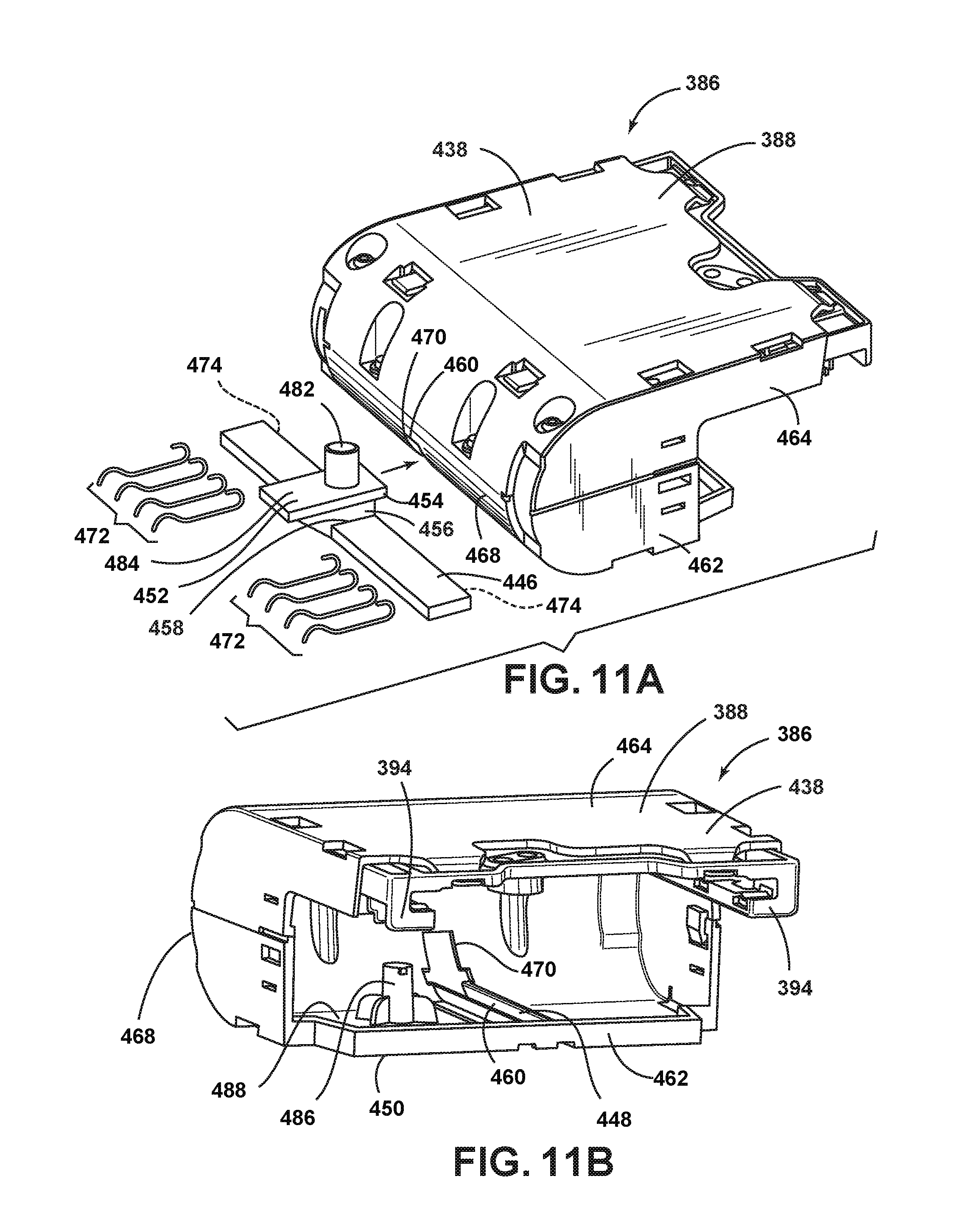
D00013
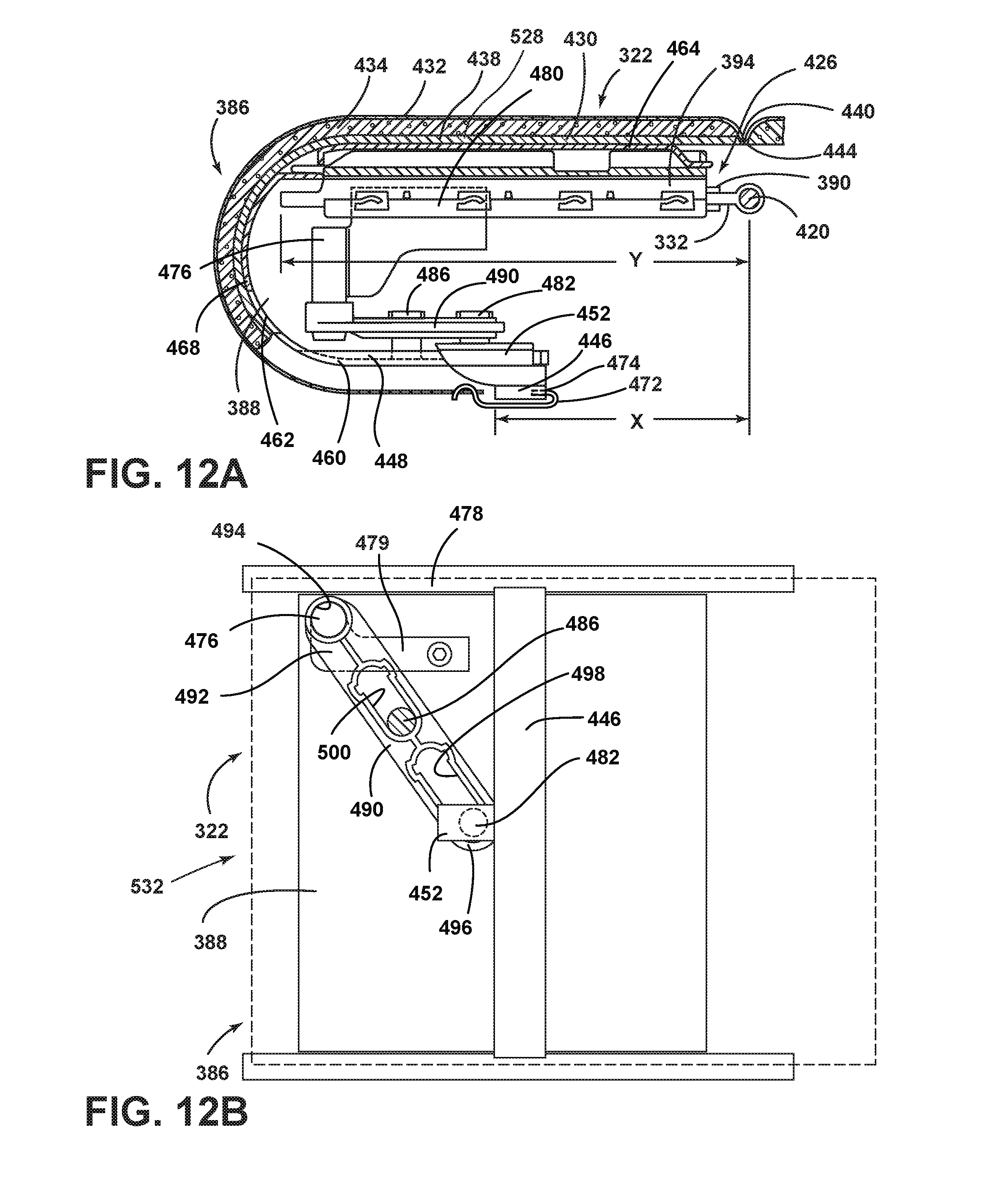
D00014
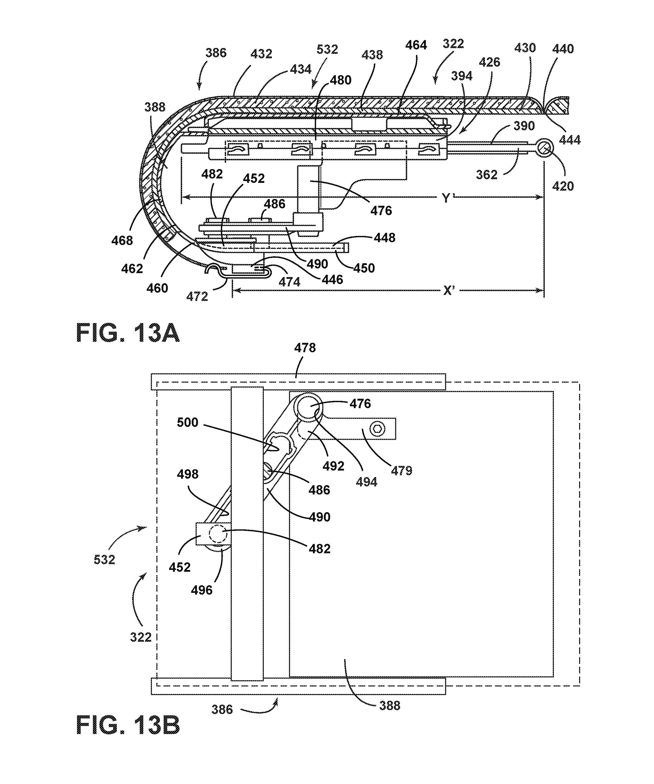
D00015
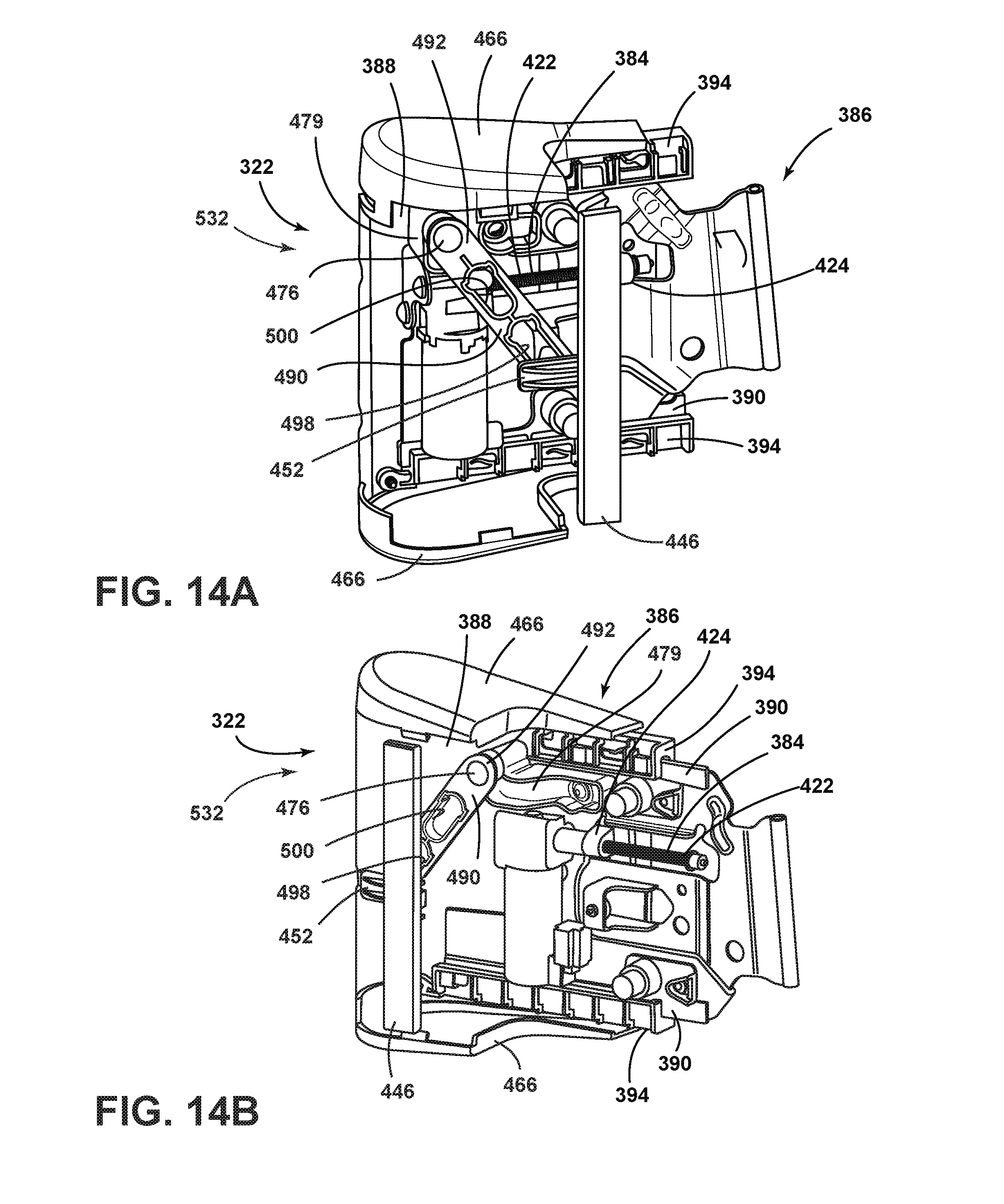
D00016
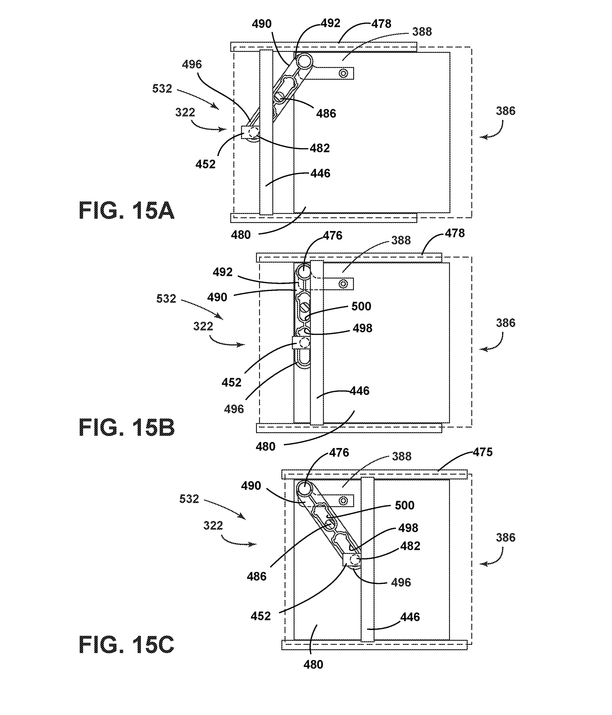
XML
uspto.report is an independent third-party trademark research tool that is not affiliated, endorsed, or sponsored by the United States Patent and Trademark Office (USPTO) or any other governmental organization. The information provided by uspto.report is based on publicly available data at the time of writing and is intended for informational purposes only.
While we strive to provide accurate and up-to-date information, we do not guarantee the accuracy, completeness, reliability, or suitability of the information displayed on this site. The use of this site is at your own risk. Any reliance you place on such information is therefore strictly at your own risk.
All official trademark data, including owner information, should be verified by visiting the official USPTO website at www.uspto.gov. This site is not intended to replace professional legal advice and should not be used as a substitute for consulting with a legal professional who is knowledgeable about trademark law.