Percutaneous valve, system and method
Eidenschink , et al.
U.S. patent number 10,226,344 [Application Number 15/244,500] was granted by the patent office on 2019-03-12 for percutaneous valve, system and method. This patent grant is currently assigned to BOSTON SCIENTIFIC SCIMED, INC.. The grantee listed for this patent is BOSTON SCIENTIFIC SCIMED, INC.. Invention is credited to William J. Drasler, Tracee Eidenschink, Craig L. Kveen, Joseph M. Thielen.

| United States Patent | 10,226,344 |
| Eidenschink , et al. | March 12, 2019 |
Percutaneous valve, system and method
Abstract
Apparatus, systems, and methods for percutaneous valve replacement and/or augmentation are provided. The apparatus includes a valve having a valve frame, a valve leaflet coupled to the valve frame, and a leaflet transition member coupled to the valve leaflet. The valve leaflet and leaflet transition member can transition from a first position where the valve leaflet and leaflet frame are at least partially outside a lumen of the valve frame to a second position where the valve leaflet and the leaflet transition member are within the lumen of the valve frame.
| Inventors: | Eidenschink; Tracee (Wayzata, MN), Thielen; Joseph M. (Buffalo, MN), Drasler; William J. (Minnetonka, MN), Kveen; Craig L. (Maple Grove, MN) | ||||||||||
|---|---|---|---|---|---|---|---|---|---|---|---|
| Applicant: |
|
||||||||||
| Assignee: | BOSTON SCIENTIFIC SCIMED, INC.
(Maple Grove, MN) |
||||||||||
| Family ID: | 39472585 | ||||||||||
| Appl. No.: | 15/244,500 | ||||||||||
| Filed: | August 23, 2016 |
Prior Publication Data
| Document Identifier | Publication Date | |
|---|---|---|
| US 20170165069 A1 | Jun 15, 2017 | |
Related U.S. Patent Documents
| Application Number | Filing Date | Patent Number | Issue Date | ||
|---|---|---|---|---|---|
| 13925440 | Aug 23, 2016 | 9421083 | |||
| 13166150 | Jun 25, 2013 | 8470023 | |||
| 12012898 | Jun 28, 2011 | 7967853 | |||
| 60899446 | Feb 5, 2007 | ||||
| Current U.S. Class: | 1/1 |
| Current CPC Class: | A61F 2/966 (20130101); A61F 2/95 (20130101); A61F 2/2418 (20130101); A61F 2/2427 (20130101); A61F 2/2475 (20130101); A61F 2/2433 (20130101); A61F 2/2436 (20130101); A61F 2/06 (20130101); A61F 2250/0098 (20130101); A61F 2220/0008 (20130101); A61F 2220/0058 (20130101); A61F 2220/0016 (20130101); A61F 2230/0013 (20130101) |
| Current International Class: | A61F 2/24 (20060101); A61F 2/966 (20130101) |
References Cited [Referenced By]
U.S. Patent Documents
| 3671979 | June 1972 | Moulopoulos |
| 4291420 | September 1981 | Reul |
| 4787901 | November 1988 | Baykut |
| 4872874 | October 1989 | Taheri |
| 4935030 | June 1990 | Alonso |
| 4994077 | February 1991 | Dobben |
| 5002567 | March 1991 | Bona et al. |
| 5141491 | August 1992 | Bowald |
| 5163953 | November 1992 | Vince |
| 5219355 | June 1993 | Parodi et al. |
| 5254127 | October 1993 | Wholey et al. |
| 5327774 | July 1994 | Nguyen et al. |
| 5332402 | July 1994 | Teitelbaum |
| 5370685 | December 1994 | Stevens |
| 5411552 | May 1995 | Andersen et al. |
| 5469868 | November 1995 | Reger |
| 5480423 | January 1996 | Ravenscroft et al. |
| 5500014 | March 1996 | Quijano et al. |
| 5545214 | August 1996 | Stevens |
| 5554185 | September 1996 | Block et al. |
| 5643208 | July 1997 | Parodi |
| 5693087 | December 1997 | Parodi |
| 5713953 | February 1998 | Vallana et al. |
| 5716370 | February 1998 | Williamson, IV |
| 5735859 | April 1998 | Fischell et al. |
| 5741326 | April 1998 | Solovay |
| 5741333 | April 1998 | Frid |
| 5800506 | September 1998 | Perouse |
| 5824061 | October 1998 | Quijano et al. |
| 5879320 | March 1999 | Cazenave |
| 5895419 | April 1999 | Tweden et al. |
| 5910170 | June 1999 | Reimink et al. |
| 6010531 | January 2000 | Donlon et al. |
| 6042607 | March 2000 | Williamson, IV |
| 6139575 | October 2000 | Shu et al. |
| 6287334 | September 2001 | Moll et al. |
| 6299637 | October 2001 | Shaolian et al. |
| 6302917 | October 2001 | Dua et al. |
| 6312447 | November 2001 | Grimes |
| 6355030 | March 2002 | Aldrich et al. |
| 6402780 | June 2002 | Williamson, IV et al. |
| 6419696 | July 2002 | Ortiz et al. |
| 6425916 | July 2002 | Garrison |
| 6440164 | August 2002 | DiMatteo et al. |
| 6451054 | September 2002 | Stevens |
| 6454799 | September 2002 | Schreck |
| 6461366 | October 2002 | Seguin |
| 6503272 | January 2003 | Duerig et al. |
| 6508833 | January 2003 | Pavcnik et al. |
| 6530952 | March 2003 | Vesely |
| 6564805 | May 2003 | Garrison et al. |
| 6569196 | May 2003 | Vesely |
| 6602286 | August 2003 | Strecker |
| 6629534 | October 2003 | St. Goar et al. |
| 6635085 | October 2003 | Caffey et al. |
| 6666885 | December 2003 | Moe |
| 6666886 | December 2003 | Tranquillo et al. |
| 6669725 | December 2003 | Scott |
| 6673109 | January 2004 | Cox |
| 6676698 | January 2004 | McGuckin, Jr. et al. |
| 6676702 | January 2004 | Mathis |
| 6682558 | January 2004 | Tu et al. |
| 6682559 | January 2004 | Myers et al. |
| 6685739 | February 2004 | DiMatteo et al. |
| 6692512 | February 2004 | Jang |
| 6695866 | February 2004 | Kuehn et al. |
| 6695878 | February 2004 | McGuckin, Jr. et al. |
| 6709456 | March 2004 | Langberg et al. |
| 6709457 | March 2004 | Otte et al. |
| 6716241 | April 2004 | Wilder et al. |
| 6716244 | April 2004 | Klaco |
| 6719767 | April 2004 | Kimblad |
| 6719784 | April 2004 | Henderson |
| 6719786 | April 2004 | Ryan et al. |
| 6719787 | April 2004 | Cox |
| 6719788 | April 2004 | Cox |
| 6719789 | April 2004 | Cox |
| 6719790 | April 2004 | Brendzel et al. |
| 6723038 | April 2004 | Schroeder et al. |
| 6723122 | April 2004 | Yang et al. |
| 6723123 | April 2004 | Kazatchkov et al. |
| 6726715 | April 2004 | Sutherland |
| 6726716 | April 2004 | Marquez |
| 6726717 | April 2004 | Alfieri et al. |
| 6730118 | May 2004 | Spenser et al. |
| 6730121 | May 2004 | Ortiz et al. |
| 6730122 | May 2004 | Pan et al. |
| 6736845 | May 2004 | Marquez et al. |
| 6736846 | May 2004 | Cox |
| 6749630 | June 2004 | McCarthy et al. |
| 6752813 | June 2004 | Goldfarb et al. |
| 6752828 | June 2004 | Thornton |
| 6755857 | June 2004 | Peterson et al. |
| 6761734 | July 2004 | Suhr |
| 6761735 | July 2004 | Eberhardt et al. |
| 6764494 | July 2004 | Menz et al. |
| 6764508 | July 2004 | Roehe et al. |
| 6764509 | July 2004 | Chinn et al. |
| 6764510 | July 2004 | Vidlund et al. |
| 6767362 | July 2004 | Schreck |
| 6769434 | August 2004 | Liddicoat et al. |
| 6770083 | August 2004 | Seguin |
| 6780200 | August 2004 | Jansen |
| 6786924 | September 2004 | Ryan et al. |
| 6786925 | September 2004 | Schoon et al. |
| 6790229 | September 2004 | Berreklouw |
| 6790230 | September 2004 | Beyersdorf et al. |
| 6790231 | September 2004 | Liddicoat et al. |
| 6793673 | September 2004 | Kowalsky et al. |
| 6797000 | September 2004 | Simpson et al. |
| 6797001 | September 2004 | Mathis et al. |
| 6797002 | September 2004 | Spence et al. |
| 6802860 | October 2004 | Cosgrove et al. |
| 6805710 | October 2004 | Bolling et al. |
| 6805711 | October 2004 | Quijano et al. |
| 6810882 | November 2004 | Langberg et al. |
| 6821297 | November 2004 | Snyders |
| 6824562 | November 2004 | Mathis et al. |
| 6830584 | December 2004 | Seguin |
| 6830585 | December 2004 | Artof et al. |
| 6837902 | January 2005 | Nguyen et al. |
| 6840246 | January 2005 | Downing |
| 6840957 | January 2005 | DiMatteo et al. |
| 6846324 | January 2005 | Stobie |
| 6846325 | January 2005 | Liddicoat |
| 6858039 | February 2005 | McCarthy |
| 6869444 | March 2005 | Gabbay |
| 6872226 | March 2005 | Cali |
| 6875224 | April 2005 | Grimes |
| 6875230 | April 2005 | Morita et al. |
| 6875231 | April 2005 | Anduiza et al. |
| 6881199 | April 2005 | Wilk et al. |
| 6881224 | April 2005 | Kruse et al. |
| 6883522 | April 2005 | Spence et al. |
| 6890352 | May 2005 | Lentell |
| 6890353 | May 2005 | Cohn et al. |
| 6893459 | May 2005 | Macoviak |
| 6893460 | May 2005 | Spenser et al. |
| 6896700 | May 2005 | Lu et al. |
| 6902576 | June 2005 | Drasler et al. |
| 6908478 | June 2005 | Alferness et al. |
| 6908481 | June 2005 | Cribier |
| 6911043 | June 2005 | Myers et al. |
| 6913608 | July 2005 | Liddicoat et al. |
| 6916338 | July 2005 | Speziali |
| 6918917 | July 2005 | Nguyen et al. |
| 6921407 | July 2005 | Nguyen et al. |
| 6921811 | July 2005 | Zamora et al. |
| 6926715 | August 2005 | Hauck et al. |
| 6926730 | August 2005 | Nguyen et al. |
| 6929653 | August 2005 | Strecter |
| 6932838 | August 2005 | Schwartz et al. |
| 6936067 | August 2005 | Buchanan |
| 6939359 | September 2005 | Tu et al. |
| 6942694 | September 2005 | Liddicoat et al. |
| 6945957 | September 2005 | Freyman |
| 6945978 | September 2005 | Hyde |
| 6945996 | September 2005 | Sedransk |
| 6945997 | September 2005 | Huynh et al. |
| 6949122 | September 2005 | Adams et al. |
| 6951571 | October 2005 | Srivastava |
| 6951573 | October 2005 | Dilling |
| 6955689 | October 2005 | Ryan et al. |
| 6958076 | October 2005 | Acosta et al. |
| 6962605 | November 2005 | Cosgrove et al. |
| 6964682 | November 2005 | Nguyen-Thien-Nhon et al. |
| 6964683 | November 2005 | Kowalsky et al. |
| 6964684 | November 2005 | Ortiz et al. |
| 6966925 | November 2005 | Stobie |
| 6966926 | November 2005 | Mathis |
| 6974464 | December 2005 | Quijano et al. |
| 6974474 | December 2005 | Pavcnik et al. |
| 6974476 | December 2005 | McGuckin, Jr. et al. |
| 6976995 | December 2005 | Mathis et al. |
| 6979350 | December 2005 | Moll et al. |
| 6986775 | January 2006 | Morales et al. |
| 6989027 | January 2006 | Allen et al. |
| 6989028 | January 2006 | Lashinski et al. |
| 6997950 | February 2006 | Chawla |
| 6997951 | February 2006 | Solem et al. |
| 7004176 | February 2006 | Lau |
| 7007396 | March 2006 | Rudko et al. |
| 7011669 | March 2006 | Kimblad |
| 7011681 | March 2006 | Vesely |
| 7011682 | March 2006 | Lashinski et al. |
| 7018406 | March 2006 | Seguin et al. |
| 7018407 | March 2006 | Wright et al. |
| 7018408 | March 2006 | Bailey et al. |
| 7022134 | April 2006 | Quijano et al. |
| 7025780 | April 2006 | Gabbay |
| 7033390 | April 2006 | Johnson et al. |
| 7037333 | May 2006 | Myers et al. |
| 7037334 | May 2006 | Hlavka et al. |
| 7041128 | May 2006 | McGuckin, Jr. et al. |
| 7041132 | May 2006 | Quijano et al. |
| 7044966 | May 2006 | Svanidze et al. |
| 7044967 | May 2006 | Solem et al. |
| 7048754 | May 2006 | Martin et al. |
| 7048757 | May 2006 | Shaknovich |
| 7052487 | May 2006 | Cohn et al. |
| 7052507 | May 2006 | Wakuda et al. |
| 7063722 | June 2006 | Marquez |
| 7066954 | June 2006 | Ryan et al. |
| 7070616 | July 2006 | Majercak et al. |
| 7077862 | July 2006 | Vidlund et al. |
| 7081131 | July 2006 | Thornton |
| 7087064 | August 2006 | Hyde et al. |
| 7089051 | August 2006 | Jaeverud et al. |
| 7090695 | August 2006 | Solem et al. |
| 7569071 | August 2009 | Haverkost et al. |
| 7951189 | May 2011 | Haverkost et al. |
| 2002/0013571 | January 2002 | Goldfarb et al. |
| 2002/0026216 | February 2002 | Grimes |
| 2002/0082630 | June 2002 | Menz et al. |
| 2002/0123802 | September 2002 | Snyders |
| 2002/0151970 | October 2002 | Garrison et al. |
| 2002/0183835 | December 2002 | Taylor et al. |
| 2002/0183838 | December 2002 | Liddicoat et al. |
| 2002/0198594 | December 2002 | Schreck |
| 2003/0014104 | January 2003 | Cribier |
| 2003/0050694 | March 2003 | Yang et al. |
| 2003/0130729 | July 2003 | Paniagua et al. |
| 2003/0163194 | August 2003 | Quijano et al. |
| 2003/0167071 | September 2003 | Martin et al. |
| 2003/0171806 | September 2003 | Mathis et al. |
| 2003/0199975 | October 2003 | Gabbay |
| 2003/0229394 | December 2003 | Ogle et al. |
| 2003/0229395 | December 2003 | Cox |
| 2003/0233142 | December 2003 | Morales et al. |
| 2003/0236568 | December 2003 | Hojeibane et al. |
| 2003/0236569 | December 2003 | Mathis et al. |
| 2004/0002719 | January 2004 | Oz et al. |
| 2004/0003819 | January 2004 | St. Goar et al. |
| 2004/0010305 | January 2004 | Alferness et al. |
| 2004/0015230 | January 2004 | Moll et al. |
| 2004/0015232 | January 2004 | Shu et al. |
| 2004/0015233 | January 2004 | Jansen |
| 2004/0019374 | January 2004 | Hojeibane et al. |
| 2004/0019377 | January 2004 | Taylor et al. |
| 2004/0019378 | January 2004 | Hlavka et al. |
| 2004/0024447 | February 2004 | Haverich |
| 2004/0024451 | February 2004 | Johnson et al. |
| 2004/0024452 | February 2004 | Kruse et al. |
| 2004/0030321 | February 2004 | Fangrow |
| 2004/0030381 | February 2004 | Shu |
| 2004/0030382 | February 2004 | St. Goar et al. |
| 2004/0030405 | February 2004 | Carpentier et al. |
| 2004/0034380 | February 2004 | Woolfson et al. |
| 2004/0034411 | February 2004 | Quijano et al. |
| 2004/0039436 | February 2004 | Spenser et al. |
| 2004/0039442 | February 2004 | St. Goar et al. |
| 2004/0039443 | February 2004 | Solem et al. |
| 2004/0044350 | March 2004 | Martin et al. |
| 2004/0044365 | March 2004 | Bachman |
| 2004/0044403 | March 2004 | Bischoff et al. |
| 2004/0049207 | March 2004 | Goldfarb et al. |
| 2004/0049211 | March 2004 | Tremulis et al. |
| 2004/0049266 | March 2004 | Anduiza et al. |
| 2004/0059351 | March 2004 | Eigler et al. |
| 2004/0059411 | March 2004 | Strecker |
| 2004/0059412 | March 2004 | Lytle et al. |
| 2004/0060161 | April 2004 | Leal et al. |
| 2004/0073301 | April 2004 | Donlon et al. |
| 2004/0073302 | April 2004 | Rourke et al. |
| 2004/0078072 | April 2004 | Tu et al. |
| 2004/0078074 | April 2004 | Anderson et al. |
| 2004/0082910 | April 2004 | Constantz et al. |
| 2004/0082923 | April 2004 | Field |
| 2004/0082991 | April 2004 | Nguyen et al. |
| 2004/0087975 | May 2004 | Lucatero et al. |
| 2004/0088045 | May 2004 | Cox |
| 2004/0088046 | May 2004 | Speziali |
| 2004/0092858 | May 2004 | Wilson et al. |
| 2004/0093060 | May 2004 | Seguin et al. |
| 2004/0093070 | May 2004 | Hojeibane et al. |
| 2004/0093080 | May 2004 | Helmus et al. |
| 2004/0097979 | May 2004 | Svanidze et al. |
| 2004/0098098 | May 2004 | McGuckin, Jr. et al. |
| 2004/0098112 | May 2004 | Dimatteo et al. |
| 2004/0102839 | May 2004 | Cohn et al. |
| 2004/0102840 | May 2004 | Solem et al. |
| 2004/0102842 | May 2004 | Jansen |
| 2004/0106976 | June 2004 | Bailey et al. |
| 2004/0106990 | June 2004 | Spence et al. |
| 2004/0106991 | June 2004 | Hopkins et al. |
| 2004/0111096 | June 2004 | Tu et al. |
| 2004/0117009 | June 2004 | Cali et al. |
| 2004/0122448 | June 2004 | Levine |
| 2004/0122512 | June 2004 | Navia et al. |
| 2004/0122513 | June 2004 | Navia et al. |
| 2004/0122514 | June 2004 | Fogarty et al. |
| 2004/0122515 | June 2004 | Chu |
| 2004/0122516 | June 2004 | Fogarty et al. |
| 2004/0127979 | July 2004 | Wilson et al. |
| 2004/0127980 | July 2004 | Kowalsky et al. |
| 2004/0127981 | July 2004 | Rahdert et al. |
| 2004/0127982 | July 2004 | Machold et al. |
| 2004/0133220 | July 2004 | Lashinski et al. |
| 2004/0133267 | July 2004 | Lane |
| 2004/0133273 | July 2004 | Cox |
| 2004/0138742 | July 2004 | Myers et al. |
| 2004/0138743 | July 2004 | Myers et al. |
| 2004/0138744 | July 2004 | Lashinski et al. |
| 2004/0138745 | July 2004 | Macoviak et al. |
| 2004/0148018 | July 2004 | Carpentier et al. |
| 2004/0148019 | July 2004 | Vidlund et al. |
| 2004/0148020 | July 2004 | Vidlund |
| 2004/0153052 | August 2004 | Mathis |
| 2004/0153146 | August 2004 | Lashinski et al. |
| 2004/0153147 | August 2004 | Mathis |
| 2004/0158321 | August 2004 | Reuter et al. |
| 2004/0162610 | August 2004 | Liska et al. |
| 2004/0167530 | August 2004 | Hamel |
| 2004/0167620 | August 2004 | Ortiz et al. |
| 2004/0172046 | September 2004 | Hlavka et al. |
| 2004/0176839 | September 2004 | Huynh et al. |
| 2004/0176840 | September 2004 | Langberg et al. |
| 2004/0181238 | September 2004 | Zarbatany et al. |
| 2004/0186444 | September 2004 | Daly et al. |
| 2004/0186558 | September 2004 | Pavcnik et al. |
| 2004/0186561 | September 2004 | McGuckin, Jr. et al. |
| 2004/0186563 | September 2004 | Lobbi |
| 2004/0186565 | September 2004 | Schreck |
| 2004/0186566 | September 2004 | Hindrichs et al. |
| 2004/0193191 | September 2004 | Starksen et al. |
| 2004/0193253 | September 2004 | Thorpe et al. |
| 2004/0193260 | September 2004 | Alferness et al. |
| 2004/0199155 | October 2004 | Mollenauer |
| 2004/0199183 | October 2004 | Oz et al. |
| 2004/0199191 | October 2004 | Schwartz |
| 2004/0204758 | October 2004 | Eberhardt et al. |
| 2004/0206363 | October 2004 | McCarthy et al. |
| 2004/0210240 | October 2004 | Saint |
| 2004/0210301 | October 2004 | Obermiller |
| 2004/0210303 | October 2004 | Sedransk |
| 2004/0210304 | October 2004 | Seguin et al. |
| 2004/0210305 | October 2004 | Shu et al. |
| 2004/0210306 | October 2004 | Quijano et al. |
| 2004/0210307 | October 2004 | Khairkhahan |
| 2004/0215333 | October 2004 | Duran et al. |
| 2004/0215339 | October 2004 | Drasler et al. |
| 2004/0220654 | November 2004 | Mathis et al. |
| 2004/0220657 | November 2004 | Nieminen et al. |
| 2004/0225322 | November 2004 | Garrison et al. |
| 2004/0225344 | November 2004 | Hoffa et al. |
| 2004/0225348 | November 2004 | Case et al. |
| 2004/0225352 | November 2004 | Osborne et al. |
| 2004/0225353 | November 2004 | McGuckin, Jr. et al. |
| 2004/0225354 | November 2004 | Allen et al. |
| 2004/0225355 | November 2004 | Stevens |
| 2004/0225356 | November 2004 | Frater |
| 2004/0230117 | November 2004 | Tosaya et al. |
| 2004/0230297 | November 2004 | Thornton |
| 2004/0236411 | November 2004 | Sarac et al. |
| 2004/0236418 | November 2004 | Stevens |
| 2004/0236419 | November 2004 | Milo |
| 2004/0243153 | December 2004 | Liddicoat et al. |
| 2004/0243219 | December 2004 | Fischer et al. |
| 2004/0243227 | December 2004 | Starksen et al. |
| 2004/0243228 | December 2004 | Kowalsky et al. |
| 2004/0243230 | December 2004 | Navia et al. |
| 2004/0254600 | December 2004 | Zarbatany et al. |
| 2004/0254636 | December 2004 | Flagle et al. |
| 2004/0260276 | December 2004 | Rudko et al. |
| 2004/0260317 | December 2004 | Bloom et al. |
| 2004/0260322 | December 2004 | Rudko et al. |
| 2004/0260389 | December 2004 | Case et al. |
| 2004/0260390 | December 2004 | Sarac et al. |
| 2004/0260393 | December 2004 | Rahdert et al. |
| 2004/0260394 | December 2004 | Douk et al. |
| 2004/0267357 | December 2004 | Allen et al. |
| 2005/0004583 | January 2005 | Oz et al. |
| 2005/0004667 | January 2005 | Swinford et al. |
| 2005/0010285 | January 2005 | Lambrecht et al. |
| 2005/0010287 | January 2005 | Macoviak et al. |
| 2005/0015112 | January 2005 | Cohn et al. |
| 2005/0021056 | January 2005 | St. Goar |
| 2005/0021136 | January 2005 | Xie et al. |
| 2005/0027261 | February 2005 | Weaver et al. |
| 2005/0027348 | February 2005 | Case et al. |
| 2005/0027351 | February 2005 | Reuter et al. |
| 2005/0027353 | February 2005 | Alferness et al. |
| 2005/0033398 | February 2005 | Seguin |
| 2005/0033419 | February 2005 | Alferness et al. |
| 2005/0033446 | February 2005 | Deem et al. |
| 2005/0038506 | February 2005 | Webler et al. |
| 2005/0038507 | February 2005 | Alferness |
| 2005/0043790 | February 2005 | Seguin |
| 2005/0043792 | February 2005 | Solem et al. |
| 2005/0049679 | March 2005 | Taylor et al. |
| 2005/0049692 | March 2005 | Numamoto et al. |
| 2005/0049696 | March 2005 | Siess et al. |
| 2005/0049697 | March 2005 | Sievers |
| 2005/0054977 | March 2005 | Laird et al. |
| 2005/0055079 | March 2005 | Duran |
| 2005/0055087 | March 2005 | Starksen |
| 2005/0055088 | March 2005 | Liddicoat et al. |
| 2005/0055089 | March 2005 | Macoviak et al. |
| 2005/0060029 | March 2005 | Le et al. |
| 2005/0060030 | March 2005 | Lashinski et al. |
| 2005/0065460 | March 2005 | Laird |
| 2005/0065550 | March 2005 | Starksen et al. |
| 2005/0065594 | March 2005 | Dimatteo et al. |
| 2005/0065597 | March 2005 | Lansac |
| 2005/0070998 | March 2005 | Rourke et al. |
| 2005/0075584 | April 2005 | Cali |
| 2005/0075659 | April 2005 | Realyvasquez et al. |
| 2005/0075662 | April 2005 | Pedersen et al. |
| 2005/0075712 | April 2005 | Biancucci et al. |
| 2005/0075713 | April 2005 | Biancucci et al. |
| 2005/0075717 | April 2005 | Nguyen et al. |
| 2005/0075718 | April 2005 | Nguyen et al. |
| 2005/0075719 | April 2005 | Bergheim |
| 2005/0075720 | April 2005 | Nguyen et al. |
| 2005/0075723 | April 2005 | Schroeder et al. |
| 2005/0075724 | April 2005 | Svanidze et al. |
| 2005/0075725 | April 2005 | Rowe |
| 2005/0075726 | April 2005 | Svanidze et al. |
| 2005/0075729 | April 2005 | Nguyen et al. |
| 2005/0075730 | April 2005 | Myers et al. |
| 2005/0075731 | April 2005 | Artof et al. |
| 2005/0080483 | April 2005 | Solem et al. |
| 2005/0085900 | April 2005 | Case et al. |
| 2005/0085903 | April 2005 | Lau |
| 2005/0085904 | April 2005 | Lemmon |
| 2005/0090846 | April 2005 | Pedersen et al. |
| 2005/0096735 | May 2005 | Hojeibane et al. |
| 2005/0096738 | May 2005 | Cali et al. |
| 2005/0096739 | May 2005 | Cao |
| 2005/0096740 | May 2005 | Langberg et al. |
| 2005/0101975 | May 2005 | Nguyen et al. |
| 2005/0102026 | May 2005 | Turner et al. |
| 2005/0107810 | May 2005 | Morales et al. |
| 2005/0107811 | May 2005 | Starksen et al. |
| 2005/0107812 | May 2005 | Starksen et al. |
| 2005/0107872 | May 2005 | Mensah et al. |
| 2005/0113910 | May 2005 | Paniagua et al. |
| 2005/0119673 | June 2005 | Gordon et al. |
| 2005/0119734 | June 2005 | Spence et al. |
| 2005/0119735 | June 2005 | Spence et al. |
| 2005/0125011 | June 2005 | Spence et al. |
| 2005/0131438 | June 2005 | Cohn |
| 2005/0137449 | June 2005 | Nieminen et al. |
| 2005/0137450 | June 2005 | Aronson et al. |
| 2005/0137451 | June 2005 | Gordon et al. |
| 2005/0137676 | June 2005 | Richardson et al. |
| 2005/0137681 | June 2005 | Shoemaker et al. |
| 2005/0137682 | June 2005 | Justino |
| 2005/0137685 | June 2005 | Nieminen et al. |
| 2005/0137686 | June 2005 | Salahieh et al. |
| 2005/0137688 | June 2005 | Salahieh et al. |
| 2005/0137689 | June 2005 | Salahieh et al. |
| 2005/0137690 | June 2005 | Salahieh et al. |
| 2005/0137691 | June 2005 | Salahieh et al. |
| 2005/0137692 | June 2005 | Haug et al. |
| 2005/0137693 | June 2005 | Haug et al. |
| 2005/0137694 | June 2005 | Haug et al. |
| 2005/0137696 | June 2005 | Salahieh et al. |
| 2005/0137697 | June 2005 | Salahieh et al. |
| 2005/0137698 | June 2005 | Salahieh et al. |
| 2005/0137699 | June 2005 | Salahieh et al. |
| 2005/0137700 | June 2005 | Spence et al. |
| 2005/0137701 | June 2005 | Salahieh et al. |
| 2005/0137702 | June 2005 | Haug et al. |
| 2005/0143807 | June 2005 | Pavcnik et al. |
| 2005/0143809 | June 2005 | Salahieh et al. |
| 2005/0143810 | June 2005 | Dauner et al. |
| 2005/0143811 | June 2005 | Realyvasquez |
| 2005/0149014 | July 2005 | Hauck et al. |
| 2005/0149179 | July 2005 | Mathis et al. |
| 2005/0149180 | July 2005 | Mathis et al. |
| 2005/0149181 | July 2005 | Eberhardt |
| 2005/0159810 | July 2005 | Filsoufi |
| 2005/0159811 | July 2005 | Lane |
| 2005/0165477 | July 2005 | Anduiza et al. |
| 2005/0165478 | July 2005 | Song |
| 2005/0171472 | August 2005 | Lutter |
| 2005/0171601 | August 2005 | Cosgrove et al. |
| 2005/0177227 | August 2005 | Heim et al. |
| 2005/0177228 | August 2005 | Solem et al. |
| 2005/0182483 | August 2005 | Osborne et al. |
| 2005/0184122 | August 2005 | Hlavka et al. |
| 2005/0187614 | August 2005 | Agnew |
| 2005/0187616 | August 2005 | Realyvasquez |
| 2005/0187617 | August 2005 | Navia |
| 2005/0192606 | September 2005 | Paul et al. |
| 2005/0192665 | September 2005 | Spenser et al. |
| 2005/0197692 | September 2005 | Pai et al. |
| 2005/0197693 | September 2005 | Pai et al. |
| 2005/0197694 | September 2005 | Pai et al. |
| 2005/0203549 | September 2005 | Realyvasquez |
| 2005/0203605 | September 2005 | Dolan |
| 2005/0203614 | September 2005 | Forster et al. |
| 2005/0203615 | September 2005 | Forster et al. |
| 2005/0203616 | September 2005 | Cribier |
| 2005/0203617 | September 2005 | Forster et al. |
| 2005/0203618 | September 2005 | Sharkawy et al. |
| 2005/0216039 | September 2005 | Lederman |
| 2005/0216077 | September 2005 | Mathis et al. |
| 2005/0216078 | September 2005 | Starksen et al. |
| 2005/0222675 | October 2005 | Sauter |
| 2005/0222678 | October 2005 | Lashinski et al. |
| 2005/0228422 | October 2005 | Machold et al. |
| 2005/0228479 | October 2005 | Pavcnik et al. |
| 2005/0228486 | October 2005 | Case et al. |
| 2005/0228494 | October 2005 | Marquez |
| 2005/0228495 | October 2005 | Macoviak |
| 2005/0228496 | October 2005 | Mensah et al. |
| 2005/0234541 | October 2005 | Hunt et al. |
| 2005/0234546 | October 2005 | Nugent et al. |
| 2005/0240200 | October 2005 | Bergheim |
| 2005/0240202 | October 2005 | Shennib et al. |
| 2005/0240255 | October 2005 | Schaeffer |
| 2005/0240259 | October 2005 | Sisken et al. |
| 2005/0240262 | October 2005 | White |
| 2005/0244460 | November 2005 | Alferiev et al. |
| 2005/0246013 | November 2005 | Gabbay |
| 2005/0251251 | November 2005 | Cribier |
| 2005/0256566 | November 2005 | Gabbay |
| 2005/0261704 | November 2005 | Mathis |
| 2005/0261759 | November 2005 | Lambrecht et al. |
| 2005/0267493 | December 2005 | Schreck et al. |
| 2005/0267560 | December 2005 | Bates |
| 2005/0267565 | December 2005 | Dave et al. |
| 2005/0267571 | December 2005 | Spence et al. |
| 2005/0267573 | December 2005 | Macoviak et al. |
| 2005/0267574 | December 2005 | Cohn et al. |
| 2005/0272969 | December 2005 | Alferness et al. |
| 2005/0273160 | December 2005 | Lashinski et al. |
| 2005/0278015 | December 2005 | Dave et al. |
| 2005/0283178 | December 2005 | Flagle et al. |
| 2005/0283231 | December 2005 | Haug |
| 2005/0288779 | December 2005 | Shaoulian et al. |
| 2006/0000715 | January 2006 | Whitcher et al. |
| 2006/0004439 | January 2006 | Spenser et al. |
| 2006/0004442 | January 2006 | Spenser et al. |
| 2006/0009841 | January 2006 | McGuckin et al. |
| 2006/0009842 | January 2006 | Huynh et al. |
| 2006/0013805 | January 2006 | Hebbel et al. |
| 2006/0013855 | January 2006 | Carpenter et al. |
| 2006/0015136 | January 2006 | Besselink |
| 2006/0015178 | January 2006 | Moaddeb et al. |
| 2006/0015179 | January 2006 | Bulman-Fleming et al. |
| 2006/0020275 | January 2006 | Goldfarb et al. |
| 2006/0020327 | January 2006 | Lashinski et al. |
| 2006/0020332 | January 2006 | Lashinski et al. |
| 2006/0020334 | January 2006 | Lashinski et al. |
| 2006/0020335 | January 2006 | Kowalsky et al. |
| 2006/0020336 | January 2006 | Liddicoat et al. |
| 2006/0025750 | February 2006 | Starksen et al. |
| 2006/0025784 | February 2006 | Starksen et al. |
| 2006/0025787 | February 2006 | Morales et al. |
| 2006/0025854 | February 2006 | Lashinski et al. |
| 2006/0025855 | February 2006 | Lashinski et al. |
| 2006/0025856 | February 2006 | Ryan et al. |
| 2006/0025857 | February 2006 | Bergheim et al. |
| 2006/0030747 | February 2006 | Kantrowitz et al. |
| 2006/0030866 | February 2006 | Schreck |
| 2006/0030882 | February 2006 | Adams et al. |
| 2006/0030885 | February 2006 | Hyde |
| 2006/0036317 | February 2006 | Vidlund et al. |
| 2006/0041305 | February 2006 | Lauterjung |
| 2006/0041306 | February 2006 | Vidlund et al. |
| 2006/0047297 | February 2006 | Case |
| 2006/0047338 | March 2006 | Jenson et al. |
| 2006/0047343 | March 2006 | Oviatt et al. |
| 2006/0052804 | March 2006 | Mialhe |
| 2006/0052867 | March 2006 | Revuelta et al. |
| 2006/0058817 | March 2006 | Starksen et al. |
| 2006/0058865 | March 2006 | Case et al. |
| 2006/0058871 | March 2006 | Zakay et al. |
| 2006/0058889 | March 2006 | Case et al. |
| 2006/0064115 | March 2006 | Allen et al. |
| 2006/0064116 | March 2006 | Allen et al. |
| 2006/0064118 | March 2006 | Kimblad |
| 2006/0064174 | March 2006 | Zadno |
| 2006/0069400 | March 2006 | Burnett et al. |
| 2006/0069430 | March 2006 | Rahdert et al. |
| 2006/0074483 | April 2006 | Schrayer |
| 2006/0074484 | April 2006 | Huber |
| 2006/0074485 | April 2006 | Realyvasquez |
| 2006/0085060 | April 2006 | Campbell |
| 2006/0089708 | April 2006 | Osse et al. |
| 2006/0095115 | May 2006 | Bladillah et al. |
| 2006/0095125 | May 2006 | Chinn et al. |
| 2006/0099326 | May 2006 | Keogh et al. |
| 2006/0100697 | May 2006 | Casanova |
| 2006/0100699 | May 2006 | Vidlund et al. |
| 2006/0106278 | May 2006 | Machold et al. |
| 2006/0106279 | May 2006 | Machold et al. |
| 2006/0106456 | May 2006 | Machold et al. |
| 2006/0111660 | May 2006 | Wolf et al. |
| 2006/0111773 | May 2006 | Rittgers et al. |
| 2006/0111774 | May 2006 | Samkov et al. |
| 2006/0116572 | June 2006 | Case |
| 2006/0116756 | June 2006 | Solem et al. |
| 2006/0122686 | June 2006 | Gilad et al. |
| 2006/0122692 | June 2006 | Gilad et al. |
| 2006/0122693 | June 2006 | Biadillah et al. |
| 2006/0127443 | June 2006 | Helmus |
| 2006/0129235 | June 2006 | Seguin et al. |
| 2006/0129236 | June 2006 | McCarthy |
| 2006/0135476 | June 2006 | Kutryk et al. |
| 2006/0135964 | June 2006 | Vesely |
| 2006/0135967 | June 2006 | Realyvasquez |
| 2006/0136044 | June 2006 | Osborne et al. |
| 2006/0136045 | June 2006 | Flagle et al. |
| 2006/0136052 | June 2006 | Vesely |
| 2006/0136054 | June 2006 | Berg et al. |
| 2006/0142846 | June 2006 | Pavcnik et al. |
| 2006/0142847 | June 2006 | Shaknovich |
| 2006/0142848 | June 2006 | Gabbay |
| 2006/0142854 | June 2006 | Alferness et al. |
| 2006/0149358 | July 2006 | Zilla et al. |
| 2006/0149360 | July 2006 | Schwammenthal et al. |
| 2006/0149367 | July 2006 | Sieracki |
| 2006/0149368 | July 2006 | Spence |
| 2006/0161133 | July 2006 | Laird et al. |
| 2006/0161248 | July 2006 | Case et al. |
| 2006/0161250 | July 2006 | Shaw |
| 2006/0167468 | July 2006 | Gabbay |
| 2006/0167541 | July 2006 | Lattouf |
| 2006/0167542 | July 2006 | Quintessenza |
| 2006/0167543 | July 2006 | Bailey et al. |
| 2006/0195180 | August 2006 | Kheradvar et al. |
| 2008/0319526 | December 2008 | Hill et al. |
| 2011/0230949 | September 2011 | Haverkost et al. |
| 0380666 | Aug 1990 | EP | |||
| 0466518 | Jan 1992 | EP | |||
| 2728457 | Jun 1996 | FR | |||
| 8800459 | Jan 1988 | WO | |||
| 9015582 | Dec 1990 | WO | |||
| 9501669 | Jan 1995 | WO | |||
| 9619159 | Jun 1996 | WO | |||
| 9803656 | Jan 1998 | WO | |||
| 9846115 | Oct 1998 | WO | |||
| 9904724 | Feb 1999 | WO | |||
| 0047139 | Aug 2000 | WO | |||
| 0067679 | Nov 2000 | WO | |||
| 0115650 | Mar 2001 | WO | |||
| 0117462 | Mar 2001 | WO | |||
| 0154624 | Aug 2001 | WO | |||
| 03047468 | Jun 2003 | WO | |||
| 03084443 | Oct 2003 | WO | |||
| 2004019825 | Mar 2004 | WO | |||
| 2004021893 | Mar 2004 | WO | |||
| 2004023980 | Mar 2004 | WO | |||
| 2004030568 | Apr 2004 | WO | |||
| 2004030569 | Apr 2004 | WO | |||
| 2004030570 | Apr 2004 | WO | |||
| 2004032724 | Apr 2004 | WO | |||
| 2004032796 | Apr 2004 | WO | |||
| 2004037128 | May 2004 | WO | |||
| 2004037317 | May 2004 | WO | |||
| 2004039432 | May 2004 | WO | |||
| 2004043265 | May 2004 | WO | |||
| 2004043273 | May 2004 | WO | |||
| 2004043293 | May 2004 | WO | |||
| 2004045370 | Jun 2004 | WO | |||
| 2004045378 | Jun 2004 | WO | |||
| 2004045463 | Jun 2004 | WO | |||
| 2004047677 | Jun 2004 | WO | |||
| 2004060217 | Jul 2004 | WO | |||
| 2004060470 | Jul 2004 | WO | |||
| 2004062725 | Jul 2004 | WO | |||
| 2004066803 | Aug 2004 | WO | |||
| 2004066826 | Aug 2004 | WO | |||
| 2004069287 | Aug 2004 | WO | |||
| 2004075789 | Sep 2004 | WO | |||
| 2004080352 | Sep 2004 | WO | |||
| 2004082523 | Sep 2004 | WO | |||
| 2004082527 | Sep 2004 | WO | |||
| 2004082528 | Sep 2004 | WO | |||
| 2004082536 | Sep 2004 | WO | |||
| 2004082537 | Sep 2004 | WO | |||
| 2004082538 | Sep 2004 | WO | |||
| 2004082757 | Sep 2004 | WO | |||
| 2004084746 | Oct 2004 | WO | |||
| 2004084770 | Oct 2004 | WO | |||
| 2004089246 | Oct 2004 | WO | |||
| 2004089250 | Oct 2004 | WO | |||
| 2004089253 | Oct 2004 | WO | |||
| 2004091449 | Oct 2004 | WO | |||
| 2004091454 | Oct 2004 | WO | |||
| 2004093683 | Nov 2004 | WO | |||
| 2004093726 | Nov 2004 | WO | |||
| 2004093728 | Nov 2004 | WO | |||
| 2004093730 | Nov 2004 | WO | |||
| 2004093745 | Nov 2004 | WO | |||
| 2004093935 | Nov 2004 | WO | |||
| 2004096100 | Nov 2004 | WO | |||
| 2004103222 | Dec 2004 | WO | |||
| 2004103223 | Dec 2004 | WO | |||
| 2004105584 | Dec 2004 | WO | |||
| 2004105651 | Dec 2004 | WO | |||
| 2004112582 | Dec 2004 | WO | |||
| 2004112585 | Dec 2004 | WO | |||
| 2004112643 | Dec 2004 | WO | |||
| 2004112652 | Dec 2004 | WO | |||
| 2004112657 | Dec 2004 | WO | |||
| 2004112658 | Dec 2004 | WO | |||
| 2005000152 | Jan 2005 | WO | |||
| 2005002424 | Jan 2005 | WO | |||
| 2005002466 | Jan 2005 | WO | |||
| 2005004753 | Jan 2005 | WO | |||
| 2005007017 | Jan 2005 | WO | |||
| 2005007018 | Jan 2005 | WO | |||
| 2005007036 | Jan 2005 | WO | |||
| 2005007037 | Jan 2005 | WO | |||
| 2005009285 | Feb 2005 | WO | |||
| 2005009286 | Feb 2005 | WO | |||
| 2005009505 | Feb 2005 | WO | |||
| 2005009506 | Feb 2005 | WO | |||
| 2005011473 | Feb 2005 | WO | |||
| 2005011534 | Feb 2005 | WO | |||
| 2005011535 | Feb 2005 | WO | |||
| 2005013860 | Feb 2005 | WO | |||
| 2005018507 | Mar 2005 | WO | |||
| 2005021063 | Mar 2005 | WO | |||
| 2005023155 | Mar 2005 | WO | |||
| 2005025644 | Mar 2005 | WO | |||
| 2005027790 | Mar 2005 | WO | |||
| 2005027797 | Mar 2005 | WO | |||
| 2005034812 | Apr 2005 | WO | |||
| 2005039428 | May 2005 | WO | |||
| 2005039452 | May 2005 | WO | |||
| 2005046488 | May 2005 | WO | |||
| 2005046528 | May 2005 | WO | |||
| 2005046529 | May 2005 | WO | |||
| 2005046531 | May 2005 | WO | |||
| 2005048883 | Jun 2005 | WO | |||
| 2005049103 | Jun 2005 | WO | |||
| 2005051226 | Jun 2005 | WO | |||
| 2005055811 | Jun 2005 | WO | |||
| 2005055883 | Jun 2005 | WO | |||
| 2005058206 | Jun 2005 | WO | |||
| 2005065585 | Jul 2005 | WO | |||
| 2005065593 | Jul 2005 | WO | |||
| 2005065594 | Jul 2005 | WO | |||
| 2005070342 | Aug 2005 | WO | |||
| 2005070343 | Aug 2005 | WO | |||
| 2005072654 | Aug 2005 | WO | |||
| 2005072655 | Aug 2005 | WO | |||
| 2005079706 | Sep 2005 | WO | |||
| 2005082288 | Sep 2005 | WO | |||
| 2005082289 | Sep 2005 | WO | |||
| 2005084595 | Sep 2005 | WO | |||
| 2005087139 | Sep 2005 | WO | |||
| 2005087140 | Sep 2005 | WO | |||
| 2006000763 | Jan 2006 | WO | |||
| 2006000776 | Jan 2006 | WO | |||
| 2006002492 | Jan 2006 | WO | |||
| 2006004679 | Jan 2006 | WO | |||
| 2006005015 | Jan 2006 | WO | |||
| 2006009690 | Jan 2006 | WO | |||
| 2006011127 | Feb 2006 | WO | |||
| 2006012011 | Feb 2006 | WO | |||
| 2006012013 | Feb 2006 | WO | |||
| 2006012038 | Feb 2006 | WO | |||
| 2006012068 | Feb 2006 | WO | |||
| 2006012322 | Feb 2006 | WO | |||
| 2006019498 | Feb 2006 | WO | |||
| 2006026371 | Mar 2006 | WO | |||
| 2006026377 | Mar 2006 | WO | |||
| 2006026912 | Mar 2006 | WO | |||
| 2006027499 | Mar 2006 | WO | |||
| 2006028821 | Mar 2006 | WO | |||
| 2006029062 | Mar 2006 | WO | |||
| 2006031436 | Mar 2006 | WO | |||
| 2006031469 | Mar 2006 | WO | |||
| 2006032051 | Mar 2006 | WO | |||
| 2006034245 | Mar 2006 | WO | |||
| 2006035415 | Apr 2006 | WO | |||
| 2006041505 | Apr 2006 | WO | |||
| 2006044679 | Apr 2006 | WO | |||
| 2006048664 | May 2006 | WO | |||
| 2006050459 | May 2006 | WO | |||
| 2006050460 | May 2006 | WO | |||
| 2006054107 | May 2006 | WO | |||
| 2006054930 | May 2006 | WO | |||
| 2006055982 | May 2006 | WO | |||
| 2006060546 | Jun 2006 | WO | |||
| 2006063108 | Jun 2006 | WO | |||
| 2006063181 | Jun 2006 | WO | |||
| 2006063199 | Jun 2006 | WO | |||
| 2006064490 | Jun 2006 | WO | |||
| 2006065212 | Jun 2006 | WO | |||
| 2006065930 | Jun 2006 | WO | |||
| 2006066148 | Jun 2006 | WO | |||
| 2006066150 | Jun 2006 | WO | |||
| 2006069094 | Jun 2006 | WO | |||
| 2006070372 | Jul 2006 | WO | |||
| 2006073628 | Jul 2006 | WO | |||
| 2006076890 | Jul 2006 | WO | |||
Attorney, Agent or Firm: Seager, Tufte & Wickhem LLP
Parent Case Text
CROSS-REFERENCE TO RELATED APPLICATION
This application is a continuation of U.S. application Ser. No. 13/925,440, filed Jun. 24, 2013, issued as U.S. Pat. No. 9,421,083 on Aug. 23, 2016, which is a continuation of U.S. application Ser. No. 13/166,150 filed Jun. 22, 2011, issued as U.S. Pat. No. 8,470,023 on Jun. 25, 2013, which is a continuation of U.S. application Ser. No. 12/012,898, filed Feb. 5, 2008, issued as U.S. Pat. No. 7,967,853 on Jun. 28, 2011, which claims the benefit of U.S. Provisional Application Ser. No. 60/899,446, filed Feb. 5, 2007, the entire contents of which are incorporated herein by reference.
Claims
What is claimed:
1. A system, comprising: an elongate delivery catheter including a distal end and a proximal end; a retractable sheath positioned around at least a portion of the elongate delivery catheter; a valve positioned around the distal end of the elongate delivery catheter and between the elongate delivery catheter and the retractable sheath, wherein the valve comprises an expandable valve frame including a distal end, a proximal end, and a lumen therebetween and a plurality of valve leaflets pivotably coupled to the proximal end of the expandable valve frame and having a first position in which the plurality of valve leaflets extend proximally from the proximal end of the expandable valve frame and a second position in which the plurality of valve leaflets are within the lumen of the expandable valve frame; and a number of elongate push members positioned around the elongate delivery catheter proximal of the valve; wherein the valve is configured to shift from a delivery state to a deployed state following withdrawal of the retractable sheath from the valve; wherein in the delivery state, the plurality of valve leaflets is in the first position extending away from the proximal end of the valve and the valve frame lumen, and wherein in the deployed state, the plurality of valve leaflets is in the second position disposed within the lumen of the valve.
2. The system of claim 1, further comprising an expandable balloon positioned around a distal portion of the elongate delivery catheter.
3. The system of claim 2, wherein the expandable balloon is configured to expand the expandable valve frame after the retractable sheath has been withdrawn from the valve.
4. The system of claim 2, wherein the elongate delivery catheter includes a distal tip disposed distal of the expandable balloon.
5. The system of claim 4, wherein an outer diameter of the distal tip decreases in a distal direction to a distal end of the elongate delivery catheter.
6. The system of claim 4, wherein the distal tip includes at least one proximally-extending member disposed proximate a perimeter of the distal tip.
7. The system of claim 1, wherein the number of elongate push members are configured to push the plurality of valve leaflets from the first position through the proximal end to the second position after the expandable valve frame has been expanded.
8. The system of claim 1, wherein in the second position, the plurality of valve leaflets forms a reversibly sealable opening configured to repeatedly move between an open state and a closed state for unidirectional flow of a liquid through the lumen of the valve.
9. The system of claim 1, further comprising a sealing material positioned on a periphery of the expandable valve frame.
10. The system of claim 9, wherein the sealing material is configured to swell when contacted by a liquid.
Description
TECHNICAL FIELD
The present disclosure relates generally to apparatus', systems, and methods for use in the vascular system; and more particularly to a percutaneous valve, system, and method for use in the vasculature system.
BACKGROUND
Valves can become damaged and/or diseased for a variety of reasons. Damaged and/or diseased valves are grouped according to which valve or valves are involved, and the amount of blood flow that is disrupted by the damaged and/or diseased valve. For example, the most common cardiac valve diseases occur in the mitral and aortic valves. Diseases of the tricuspid and pulmonary valves are fairly rare.
The aortic valve regulates the blood flow from the heart's left ventricle into the aorta. The aorta is the main artery that supplies oxygenated blood to the body. As a result, diseases of the aortic valve can have a significant impact on an individual's health. Examples of such diseases include aortic regurgitation and aortic stenosis.
Aortic regurgitation is also called aortic insufficiency or aortic incompetence. It is a condition in which blood flows backward from a widened or weakened aortic valve into the left ventricle of the heart. In its most serious form, aortic regurgitation is caused by an infection that leaves holes in the valve leaflets. Symptoms of aortic regurgitation may not appear for years. When symptoms do appear, it is because the left ventricle must work harder relative to an uncompromised aortic valve to make up for the backflow of blood. The ventricle eventually gets larger and fluid backs up.
Aortic stenosis is a narrowing or blockage of the aortic valve. Aortic stenosis occurs when the valve leaflets of the aorta become coated with deposits. The deposits change the shape of the leaflets and reduce blood flow through the valve. Again, the left ventricle has to work harder relative to an uncompromised aortic valve to make up for the reduced blood flow. Over time, the extra work can weaken the heart muscle.
BRIEF DESCRIPTION OF THE DRAWINGS
FIGS. 1A-1B provide an embodiment of a valve of the present disclosure.
FIGS. 2A-2B provide an embodiment of a valve of the present disclosure.
FIGS. 3A-3C illustrate an embodiment of a system according to the present disclosure.
DETAILED DESCRIPTION
Embodiments of the present disclosure are directed to an apparatus, system, and method for percutaneous valve replacement and/or augmentation. For example, the apparatus can include a valve that can be used to replace an incompetent valve (e.g., an aortic valve, a mitral valve, a tricuspid valve, or a pulmonary valve) or vein in a body lumen. Embodiments of the valve include a valve frame having frame members that define a lumen, and a valve leaflet coupled to the valve frame.
In the various embodiments, the valve leaflets extend away from the lumen of the valve. This configuration allows for more flexibility in the valve frame design as well as the valve leaflet design since the valve is not delivered to a treatment site with the valve leaflets inside the valve frame. In addition to more flexibility in design, this configuration allows for a lower profile of the delivered valve since the valve leaflets are outside the valve frame, allowing the valve frame to be compressed to a greater degree. For example, the valve frame can be at least partially balloon deployed without compressing, or sandwiching, the valve leaflets between the inflatable balloon and the valve frame. Once the valve frame is deployed, the valve leaflets and valve frame can be transitioned to within the lumen of the valve frame and the leaflet transition member can be expanded to secure the leaflet transition member and the valve leaflets into a position to function as a valve. Embodiments of the present disclosure can be used as a prosthetic cardiac valve and/or a prosthetic venous valve, as well as other valves.
The figures herein follow a numbering convention in which the first digit or digits correspond to the drawing figure number and the remaining digits identify an element or component in the drawing. Similar elements or components between different figures may be identified by the use of similar digits. For example, 110 may reference element "10" in FIG. 1, and a similar element may be referenced as 210 in FIG. 2. As will be appreciated, elements shown in the various embodiments herein can be added, exchanged, and/or eliminated so as to provide any number of additional embodiments of valve and/or system. In addition, as will be appreciated the proportion and the relative scale of the elements provided in the figures are intended to illustrate the embodiments of the present invention, and should not be taken in a limiting sense.
Various embodiments of the present disclosure are illustrated in the figures. Generally, the valve can be implanted within the fluid passageway of a body lumen, for example, for replacement or augmentation of a valve structure within the body lumen (e.g., an aortic valve), to regulate the flow of a bodily fluid through the body lumen in a single direction.
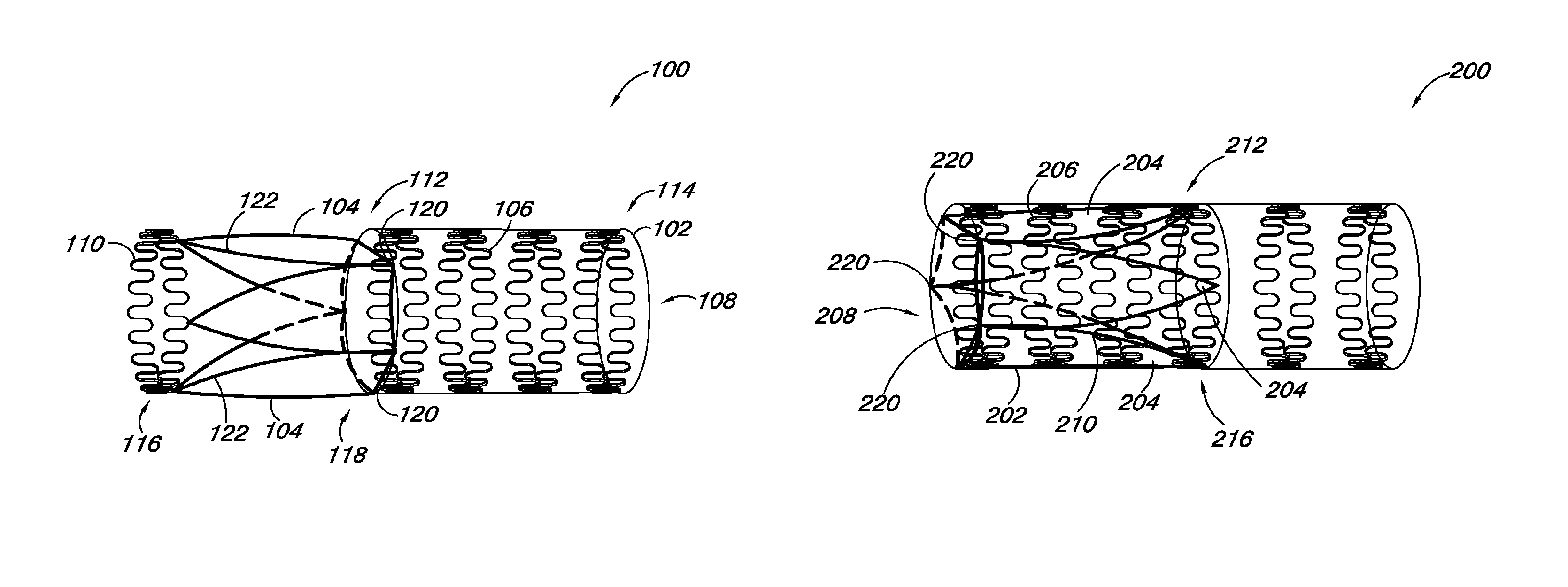
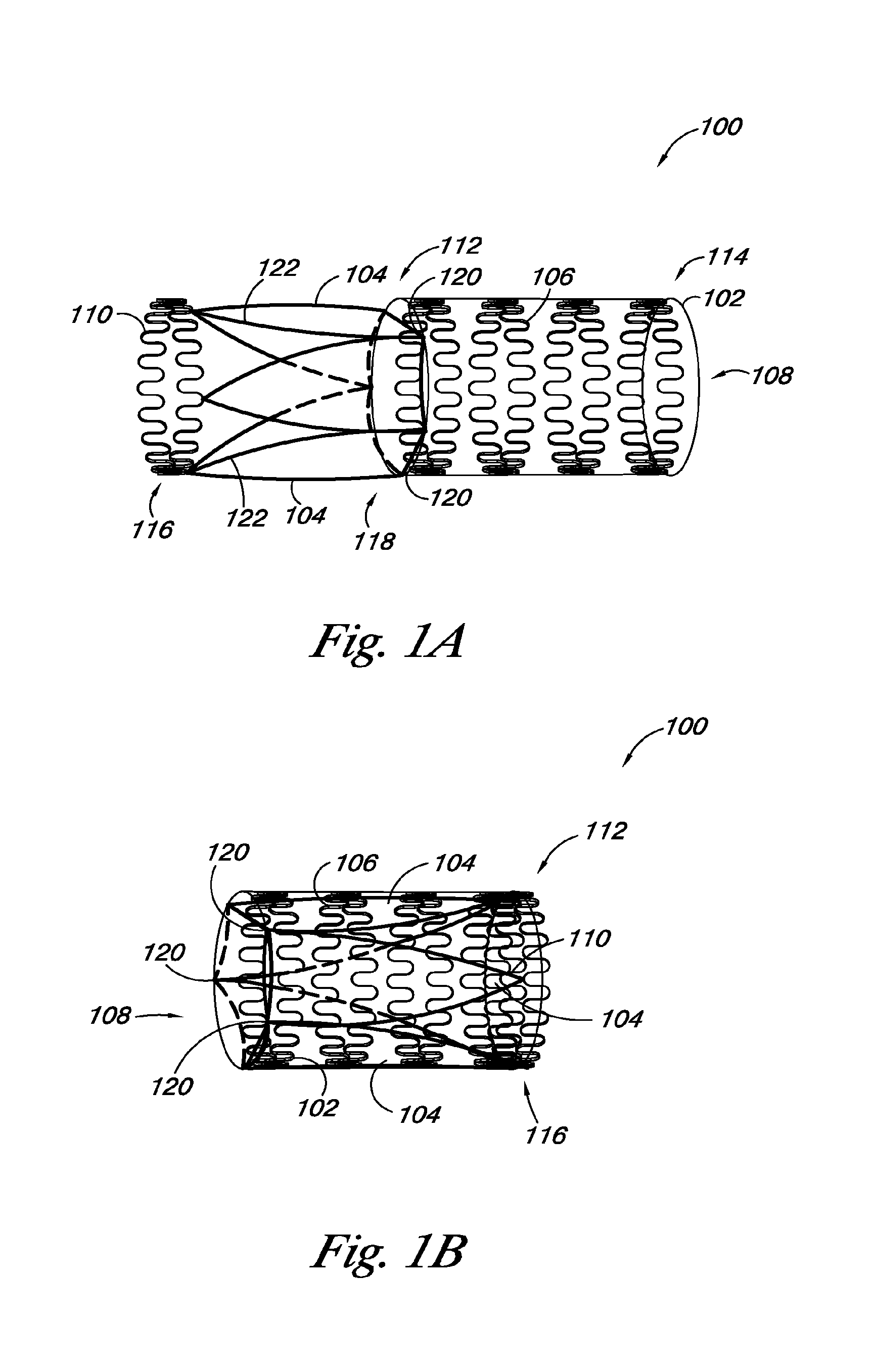
FIGS. 1A and 1B provide an embodiment of a valve 100 of the present disclosure. FIG. 1A illustrates the valve 100 with the valve leaflet 104 in a first position, while FIG. 1B illustrates the valve 100 with the valve leaflet 104 in a second position. The valve 100 includes a valve frame 102 and a valve leaflet 104 coupled to the valve frame 102. The valve frame 102 also includes frame members 106 that define a lumen 108. The valve 100 also includes a leaflet transition member 110 coupled to at least a portion of the valve leaflet 104.
As discussed herein, FIG. 1A illustrates the valve leaflet 104 and leaflet transition member 110 in a first position, where the valve leaflet 104 and leaflet transition member 110 are at least partially outside the lumen 108 of the valve frame 102 and extend away from the lumen 108. The valve leaflet 104 can also include a leaflet frame 111 that is coupled to a portion of the peripheral edge 122 of the valve leaflet 104. In some embodiments, the leaflet frame 111 can have a U-shape, leaving a portion of a distal end 118, relative to the leaflet transition member 110, of the valve leaflet 104 free to move between an open and closed position to function as a valve.
In some embodiments, the leaflet frame 111 can be coupled to the leaflet transition member 110. For example, the leaflet frame 111 can be hinged to the leaflet transition member 110 to allow the leaflet transition member 110 to move inside the leaflet frame 111 and invert the leaflet frame 111 from the first position, as shown in FIG. 1A, to the second position, as shown in FIG. 1B. The valve leaflet 104 can be coupled to the leaflet frame 111 in a variety of ways including sewing, suturing, and/or arc welding, among other methods.
In some embodiments, the valve frame 102 can have an elongate tubular structure with a proximal end 112 and a distal end 114, relative to the leaflet transition member 110. In some embodiments, portions of the frame members 106 can define the proximal and distal ends 112, 114 of the valve frame 102. In addition, the valve leaflet 104 can have a proximal end 116 and a distal end 118, relative to the leaflet transition member 110, where a portion of the distal end 118 of the valve leaflet 104 can be coupled adjacent to the proximal end 112 of the valve frame 102 at junction points 120. As used herein, "junction points" refer to places on the valve frame 102 where the valve leaflet 104 is coupled to the valve frame 102. In some embodiments, the junction points 120 can be located at a number of different positions on the valve frame 102. In some embodiments, the junction points 120 can be located at the same relative position around the valve frame 102. For example, when a valve 100 includes two valve leaflets 104, the junction points 120 can be set opposite each other in a mirror image relationship.
In embodiments where there are more than two leaflets 104, the junction points 120 can be set along the valve frame 102 at positions that are equidistant from each other. This aspect of the disclosure is illustrated in FIG. 1, which shows the valve 100 with three valve leaflets 104 having three junction points 120 set on the valve frame 102 at positions that are equidistant from each other. Alternatively, the junction points 120 can be at different relative locations along the valve frame 102. For the various embodiments, the junction points 120 can be located on the valve frame 102 such that the valve leaflet 104 can transition from a first position as shown in FIG. 1A to a second position shown in FIG. 1B, as will be discussed herein.
As illustrated in FIG. 1A, the valve 100 can include the leaflet transition member 110 coupled to at least a portion of the valve leaflet 104 and/or the leaflet frame 111. In some embodiments, the leaflet transition member 110 can be a ring structure that is coupled to the proximal end 116 of the valve leaflet 104. The leaflet transition member 110 can be expandable from a first diameter to a second diameter. As shown in FIG. 1A, the leaflet transition member 110 in the first position can have the first diameter. In various embodiments, the leaflet transition member 110 can have a serpentine shape in order to allow the leaflet transition member 110 to expand from the first diameter to the second diameter. The leaflet transition member 110 can also have other shapes, for example, the leaflet transition member 110 can include leaflet transition member 110 portions that can form a coil. The coil portions can allow the leaflet transition member 110 to have a first diameter in the first position and expand to a second diameter. The leaflet transition member 110 can also have other shapes.
In some embodiments, the leaflet transition member 110 can be formed of a shape-memory material. Examples of shape-memory materials include shape memory plastics, polymers, thermoplastic materials, and metal-alloys which are inert in the body. Some shape-memory materials, (e.g., nickel-titanium alloys) can be temperature-sensitive and change shape at a designated temperature or temperature range. Shape memory metal-alloys are generally made from nickel and titanium in specific ratios, commonly known as Nitinol. Other materials are also possible.
FIG. 1B provides an embodiment of a valve 100 of the present disclosure when the valve leaflets 104 and leaflet frame 110 are in the second position. As illustrated, the valve leaflet 104 and leaflet transition member 110 can transition from the first position to the second position by pivoting the valve leaflet 104 inside the valve frame 102 at the junction points 120. In the second position, the proximal end 116 of the valve leaflet 104 and at least a portion of the leaflet transition member 110 are within the lumen 108 of the valve frame 102. In some embodiments, the leaflet transition member 110 in the second position can be coupled adjacent to the distal end 114 of the valve frame 102, for example, the leaflet transition member 110 can be coupled to frame members 106 on the distal end 114 of the valve frame 102.
As discussed herein, the leaflet transition member 110 can expand from a first diameter to a second diameter. The leaflet transition member 110 can expand to the second diameter to secure the leaflet frame 111 to the valve frame 102 and/or to secure the leaflet transition member 110 in the second position. As illustrated in FIG. 1B, the leaflet transition member 110 can have a serpentine shape to allow the leaflet transition member 110 to expand, however, the serpentine shape can also allow portions of the leaflet transition member 110 to expand through the valve frame 102 and between the frame members 106. By expanding through the valve frame 102 and between the frame members, the leaflet transition member 110 can be held in the second position.
For the various embodiments, the valve frame 102 can be formed of a balloon expandable material, as discussed herein. The valve frame 102 can also be formed of a material with a spring bias. The valve frame 102 can also be a shape memory material, as discussed herein. Other materials are also possible.
For the various embodiments, the frame members 106 and/or the leaflet transition member 110 can have similar and/or different cross-sectional geometries along their length. The similarity and/or the differences in the cross-sectional geometries can be selected based on one or more desired functions to be elicited from each portion of the valve frame 102. Examples of cross-sectional geometries include rectangular, non-planar configuration (e.g., bent), round (e.g., circular, oval, and/or elliptical), polygonal, arced, and tubular. Other cross-sectional geometries are possible.
The valve 100 can further include one or more radiopaque markers (e.g., tabs, sleeves, welds). For example, one or more portions of the valve frame 102 can be formed from a radiopaque material. Radiopaque markers can be attached to and/or coated onto one or more locations along the valve frame 102. Examples of radiopaque material include, but are not limited to, gold, tantalum, and platinum. The position of the one or more radiopaque markers can be selected so as to provide information on the position, location, and orientation of the valve 100 during its implantation.
The valve 100 further includes the leaflets 104 having surfaces defining a reversibly sealable opening for unidirectional flow of a liquid through the valve 100. Each of the valve leaflets 104 are coupled to the valve frame 102, where the leaflets 104 can repeatedly move between an open state and a closed state for unidirectional flow of a liquid through a lumen of the valve 100. For example, the leaflets 104 can be coupled to the proximal end 112 of the valve frame 102 so as to span and control fluid flow through the lumen 108 of the valve 100. For the present embodiment, the valve 100 includes three of the valve leaflets 104 for a tri-leaflet configuration. As appreciated, mono-leaflet, bi-leaflet and/or other multi-leaflet configurations are also possible.
In some embodiments, the leaflets 104 can be derived from autologous, allogeneic or xenograft material. As will be appreciated, sources for xenograft material (e.g., cardiac valves) include, but are not limited to, mammalian sources such as porcine, equine, and sheep. Additional biologic materials from which to form the valve leaflets 104 include, but are not limited to, explanted veins, pericardium, facia lata, harvested cardiac valves, bladder, vein wall, various collagen types, elastin, intestinal submucosa, and decellularized basement membrane materials, such as small intestine submucosa (SIS), amniotic tissue, or umbilical vein.
Alternatively, the leaflets 104 can be formed from a synthetic material. Possible synthetic materials include, but are not limited to, expanded polytetrafluoroethylene (ePTFE), polytetrafluoroethylene (PTFE), polystyrene-polyisobutylene-polystyrene (SIBS), polyurethane, segmented poly(carbonate-urethane), polyester, polyethylene (PE), polyethylene terephthalate (PET), silk, urethane, Rayon, Silicone, or the like. In an additional embodiment, the synthetic material can also include metals, such as stainless steel (e.g., 316L) and nitinol. These synthetic materials can be in a woven, a knit, a cast or other known physical fluid-impermeable or permeable configurations. In addition, gold plated metals can be embedded in the leaflet 104 material (e.g., a sandwich configuration) to allow for visualization of the leaflets 104 post placement.
As will be appreciated, the valve 100 can be treated and/or coated with any number of surface or material treatments. Examples of such treatments include, but are not limited to, bioactive agents, including those that modulate thrombosis, those that encourage cellular ingrowth, throughgrowth, and endothelialization, those that resist infection, and those that reduce calcification.
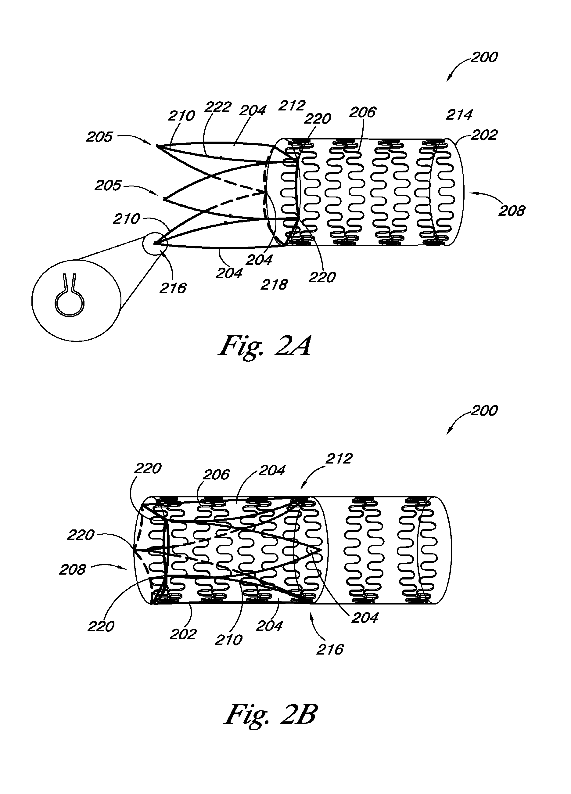
FIGS. 2A and 2B provide an embodiment of a valve 200 of the present disclosure. As discussed herein, the valve 200 includes a valve frame 202 and a valve leaflet 204 coupled to the valve frame 202. The valve frame 202 also includes frame members 206 that define a lumen 208. As shown in FIGS. 2A and 2B, the valve leaflets 204 can include a leaflet frame 211, as discussed herein, coupled to at least a portion of the peripheral edge 222 of the valve leaflets 204. In such embodiments, the leaflet frame 211 can act as the leaflet transition member 210.
FIG. 2A illustrates the valve leaflet 204 and leaflet transition member 210 (i.e., leaflet frame 211) in a first position, where the valve leaflet 204 and leaflet transition member 210 are at least partially outside the lumen 208 of the valve frame 202 and extend away from the lumen 208. FIG. 2B illustrates the valve 200 where the valve leaflet 204 and leaflet transition member 210 are in a second position within the lumen 208 of the valve frame 202, as discussed herein.
As shown in FIGS. 2A and 2B, in some embodiments, the leaflet frame 211 can be coupled to a portion of a peripheral edge 222 of the valve leaflet 204. In such embodiments, the leaflet frame 211 can form the outside boundary of a portion of the valve leaflet 204 and can hold the valve leaflet 204 in a desired position. As discussed herein, the valve leaflet 204 can have a proximal end 216 and a distal end 218, where a portion of the distal end 218 of the valve leaflet 204 can be coupled adjacent to the proximal end 212 of the valve frame 202 at junction points 220. In some embodiments, the valve leaflet 204 can be coupled to the valve frame 202 such that the valve leaflet 204 can pivot inside the valve frame 302 at the junction points 220.
In other embodiments, the leaflet transition member 210 (i.e., leaflet frame 211) can be coupled to the peripheral edge 222 of the valve leaflet 204 such that the leaflet transition member 210 is coupled to the proximal end 212 of the valve frame 202. In such embodiments, the leaflet transition member 210 can be hinged to a portion of the valve frame 202 to couple the valve frame 202 and the valve leaflet 204. Also, hinging the leaflet transition member 210 to the valve frame 202 can allow the leaflet transition member 210 and the valve leaflet 204 to transition from the first position to the second position, as shown in FIGS. 2A and 2B.
In addition, as discussed herein, the leaflet transition member 210 can be coupled to the valve frame 202 to hold the leaflet frame 210 in the second position. In such embodiments, the leaflet transition member 210 can include mechanical members 205 to hold the leaflet transition member 210 to the frame members 206 of the valve frame 202. One embodiment of a mechanical member 205 is shown in FIG. 2A as a close-up view. In this embodiment, the mechanical member 205 can be in the form of a clip, where a frame member 206 can slide into the clip 205 to secure the leaflet frame 210 to the valve frame 202. In another embodiment, the mechanical member 205 can be a hook that hooks the leaflet transition member 210 to the frame members in several different locations. Other mechanical member 205 configurations are also possible.
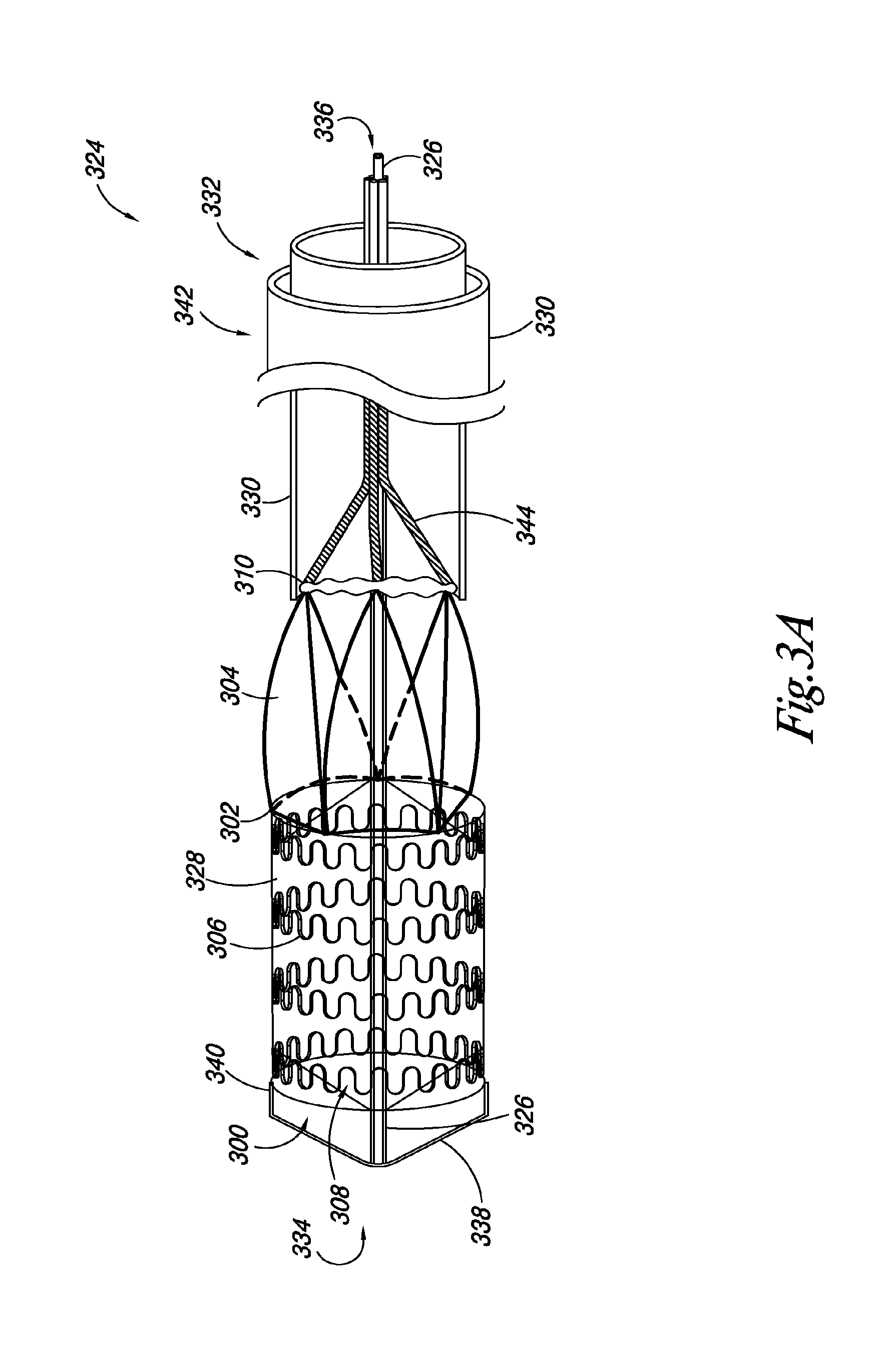
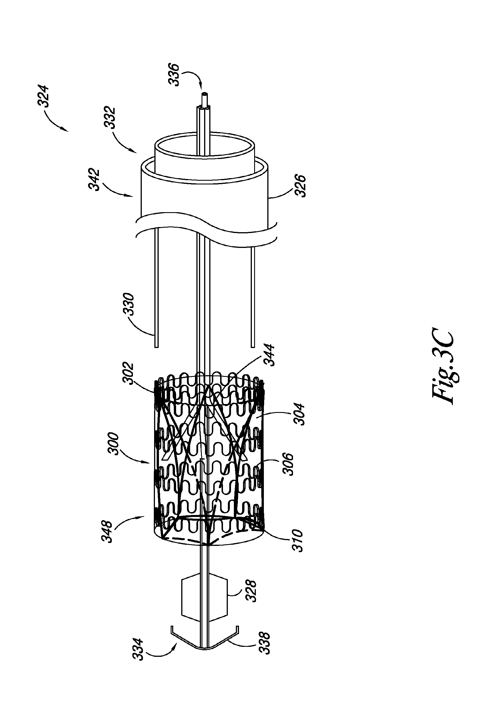
FIGS. 3A-3C illustrate an embodiment of a system 324 according to the present disclosure. The system 324 includes a valve 300, as described herein, releasably joined to an elongate delivery catheter 326 and an expandable balloon 328 positioned around at least a portion of the elongate delivery catheter 326. The system 324 also includes a retractable sheath 330 positioned around at least a portion of the elongate delivery catheter 326. Also, a portion of the valve 300 is positioned between the elongate delivery catheter 326 and the retractable sheath 330. For example, FIG. 3A illustrates an embodiment in which the retractable sheath 330 is positioned around at least a portion of the delivery catheter 326 to releasably hold the leaflet transition member 310 in a delivery state.
In some embodiments, the retractable sheath 330 can be positioned such that the retractable sheath holds the valve frame 302 and the leaflet transition member 310 in a delivery state. In such embodiments, the retractable sheath 330 can be partially retracted to allow the valve frame 302 to radially expand while holding the leaflet transition member 310 in the delivery state. FIG. 3B illustrates an embodiment in which valve 300 has expanded to its deployed state, as discussed herein.
In the embodiments illustrated in FIGS. 3A-3C, the delivery catheter 326 includes an elongate body having a proximal end 332 and a distal end 334. A catheter lumen 336 can extend through the proximal and distal ends 332, 334. In some embodiments, the catheter lumen 336 can receive a guidewire for guiding the placement of the valve 300 in the vasculature.
In some embodiments, the elongate delivery catheter 326 can include a distal tip 338. The distal tip 338 can have a conical configuration, where the tip 338 diameter decreases in size to a point at the distal end 334 of the elongate delivery catheter 326.
In addition, in such embodiments, the retractable sheath 330 can move longitudinally (e.g., slide) relative the delivery catheter 326 to allow the valve 300 to radially expand from its delivery state to its deployed state. In some embodiments, moving the retractable sheath 330 relative the delivery catheter 326 can be accomplished by pulling a proximal end 342 of the sheath 330 relative a proximal end 332 of the delivery catheter 326.
FIG. 3B illustrates an embodiment where the valve 300 has been radially expanded. In some embodiments, the valve 300 can be balloon expandable. In other embodiments, the retractable sheath 330, if positioned over the valve frame 302, can be retracted relative the valve 300 to allow the valve 300 to be radially expanded using the expandable balloon 328. In such embodiments, the elongate delivery catheter 326 can include a lumen fluidly attached to the expandable balloon 328 to allow the balloon 328 to be filled with fluid to radially expand the balloon 328, and thus the valve 300.
In some embodiments, the valve 300 can be formed of a material with a spring bias, where the valve 300 can expand when the sheath 330 has been removed. In such embodiments, the expandable balloon 328 can be used to position the valve 300 and/or secure the valve 300 inside a body lumen. Examples of materials with a spring bias can include, but are not limited to, medical grade stainless steel (e.g., 316L), titanium, tantalum, platinum alloys, niobium alloys, cobalt alloys, alginate, or combinations thereof.
In some embodiments, the expandable balloon 328 can be a perfusion balloon. A perfusion balloon can be used to radially expand the valve frame 302 while allowing fluid, for example, blood, to pass through the delivery catheter 326 and valve 300 while the valve 300 is being positioned in the vasculature.
In the embodiment illustrated in FIGS. 3A-3C, the valve 300 includes a valve frame 302 having frame members defining a lumen 308, a valve leaflet 304 attached to a portion of the valve frame 302, and a leaflet transition member 310 attached to at least a portion of the valve leaflet 304. FIG. 3A illustrates an embodiment where the valve leaflet 304 and leaflet transition member 310 are in a first position extending away from the lumen 308 of the valve 300. Although the embodiments illustrated in FIGS. 3A-3C show a valve 300 including a leaflet transition member 310 and a leaflet frame 311, the present disclosure includes embodiments where the leaflet frame 311 acts as the leaflet transition member 310, as discussed herein.
To transition the valve leaflets 304 and leaflet transition member 310 from the first position to a second position within the lumen 308 of the valve frame 302, the elongate delivery catheter 326 can include a number of elongate push members 344 releasably coupled to the leaflet transition member 310. The elongate push members 344 can be positioned around the elongate delivery catheter 326, and can be used to push the leaflet transition member 310 inside the lumen 308 of the valve 300.
In some embodiments, the elongate push members 344 can move in a longitudinal direction relative the elongate delivery catheter 326. The elongate push members 344 can be formed of a plastic material, where the elongate push members 344 are moved into the lumen 308 of the valve 300 to push the leaflet transition member 310 and the valve leaflet 304 from the first position to the second position. The elongate push members 344 can also be formed of different materials. For example, the elongate push members 344 can be formed of a wire or thread releasably attached to the leaflet transition member 310. As such, as the elongate push members 344 are moved into the lumen 308 of the valve 300, the elongate push members 344 would pull the leaflet transition member 310 and the valve leaflet 304 from the first position to the second position. Other methods of transitioning the leaflet transition member 310 and the valve leaflet 304 from the first position to the second position are also possible.
As discussed herein, FIG. 3B illustrates an embodiment where the valve frame 302 is radially expanded. Also shown is how the leaflet transition member 310 can remain in a contracted state while the valve frame 302 is expanded. In some embodiments, the leaflet transition member 310 can be formed of a shape-memory material, such as a nickel-titanium alloy, where the leaflet transition member 310 and/or leaflet frame 311 is restrained in a contracted state by the retractable sheath 330.
In some embodiments, the leaflet transition member 310 is formed of a shape memory material, as discussed herein. In such embodiments, the retractable sheath 330 can be used to hold the leaflet transition member 310 in the first position while the valve frame 302 is radially expanded.
FIG. 3B also illustrates how a portion of the leaflet frame 311 can expand when the valve frame 302 is radially expanded. In some embodiments, the leaflet frame 311 can be coupled to the proximal end 312 of the valve frame 302 such that when the valve frame 302 is radially expanded, the leaflet frame 311 is coupled to the valve frame 302 at junction points 320 that are equidistant apart, as discussed herein.
In addition, in some embodiments, the leaflet frame 311 can be formed of a shape memory material to allow the leaflet frame 311 to deform when the valve frame 302 is expanded and the leaflet transition member 310 is held in the delivery state. In such embodiments, once the valve frame 302 is expanded and the valve leaflet 304 and leaflet transition member 310 are in the second position, the leaflet frame 311 can transition to a deployed state to hold the valve leaflet 304 in a position to act as a valve.
As discussed herein, the number of elongate push members 344 can be used to push the leaflet transition member 310 inside the lumen 308 of the valve frame 302 to place the valve leaflet 304 and leaflet transition member 310 into the second position. Once the leaflet transition member 310 is inside the lumen 308, the leaflet transition member 310 can be radially expanded inside the valve frame 302 and the number of elongate members 344 can be released from the leaflet transition member 310. In some embodiments, the leaflet transition member 310 can be formed of a material with a spring bias, as discussed herein, and expand when the retractable sheath 330 is retracted relative the valve 300 to release the leaflet transition member 310 while the elongate push members 344 hold the leaflet transition member 310 in place within the lumen 308 of the valve 300. Once the leaflet transition member 310 is expanded, the elongate push members 344 and the delivery catheter 326 can be retracted through the valve 300.
Alternatively, in embodiments where the leaflet transition member 310 is formed of a shape memory material, the leaflet frame 310 can radially expand when the retractable sheath 330 is retracted relative the valve 300 and the leaflet transition member 310 warms to a certain temperature, for example, at or below normal body temperature (e.g., 37 degrees Celsius).
FIG. 3C illustrates an embodiment of the valve frame 302 radially expanded, where the valve leaflet 304 and leaflet transition member 310 are in the second position. As illustrated, once the leaflet transition member 310 and the valve frame 302 are expanded, the expandable balloon 328 and distal tip 338 can be retracted through the lumen 308 of the valve frame 302.
In some embodiments, the leaflet transition member 310 can be secured to the valve frame 302 once the leaflet transition member 310 is in the second position and both the leaflet transition member 310 and the valve frame 302 are radially expanded. For example, as discussed herein, the leaflet transition member 310 can expand from a first diameter to a second diameter where portions of the leaflet transition member 310 extend through the valve frame 302 and between the frame members 306 to secure the leaflet transition member 310 in the second position. In other embodiments, the leaflet transition member 310 and/or leaflet frame 311 can include mechanical members, as discussed herein, to secure the leaflet transition member 310 and/or leaflet frame 311 to the valve frame 302. A combination of mechanical members and expanding the leaflet transition member 310 to extend portions of the leaflet transition member 310 through the valve frame 302 and between the frame members 306 is also possible.
Embodiments of the system 324 can further include an expandable filter that forms a portion of the retractable sheath. Examples of such an embodiment can be found in U.S. Provisional Patent application 60/899,444 and co-pending U.S. patent application Ser. No. 12/012,911 entitled "Percutaneous Valve, System and Method" (docket number 07-00015US), both of which are hereby incorporated by reference in their entirety.
Each of the delivery catheter 326, the retractable sheath 330, and/or the second retractable sheath 346 can be formed of a number of materials. Materials include polymers, such as PVC, PE, POC, PET, polyamide, mixtures, and block co-polymers thereof. In addition, each of the delivery catheter 326, the retractable sheath 330, and/or the second retractable sheath 346 can have a wall thickness and an inner diameter sufficient to allow the structures to slide longitudinally relative each other, as described herein, and to maintain the valve 300 in a delivery state, as discussed herein.
In an additional embodiment, the valve 300 can further include a sealing material 348 positioned on the periphery of the valve frame 302. In one embodiment, once implanted the sealing material 348 can swell due the presence of liquid to occupy volume between the valve frame 302 and the tissue on which the valve 300 has been implanted so as to prevent leakage of the liquid around the outside of the valve 300.
Embodiments can also include a sealing material positioned on a portion of the peripheral edge 322 of the leaflet frame 311 to seal the leaflet frame 311 to the valve frame 302.
A variety of suitable materials for the sealing material 348 are possible. For example, the sealing material 348 can be selected from the general class of materials that include polysaccharides, proteins, and biocompatible gels. Specific examples of these polymeric materials can include, but are not limited to, those derived from poly(ethylene oxide) (PEO), poly(ethylene glycol) (PEG), poly(vinyl alcohol) (PVA), poly(vinylpyrrolidone) (PVP), poly(ethyloxazoline) (PEOX) polyaminoacids, pseudopolyamino acids, and polyethyloxazoline, as well as copolymers of these with each other or other water soluble polymers or water insoluble polymers. Examples of the polysaccharide include those derived from alginate, hyaluronic acid, chondroitin sulfate, dextran, dextran sulfate, heparin, heparin sulfate, heparan sulfate, chitosan, gellan gum, xanthan gum, guar gum, water soluble cellulose derivatives, and carrageenan. Examples of proteins include those derived from gelatin, collagen, elastin, zein, and albumin, whether produced from natural or recombinant sources.
In an additional embodiment, the valve 300 of the present disclosure can include anchoring members attached to the valve frame 302 or frame members 306. Anchoring members can include barbs, hooks, etc.
The embodiments of the valve described herein may be used to replace, supplement, or augment valve structures within one or more lumens of the body. For example, embodiments of the present invention may be used to replace an incompetent cardiac valve of the heart, such as the aortic, pulmonary and/or mitral valves of the heart. In one embodiment, the native cardiac valve can either remain in place or be removed (e.g., via a valvoplasty procedure) prior to implanting the cardiac valve of the present disclosure.
In addition, positioning the system having the valve as discussed herein includes introducing the system into the cardiovascular system of the patient using minimally invasive percutaneous, transluminal techniques. For example, a guidewire can be positioned within the cardiovascular system of a patient that includes the predetermined location. The system of the present disclosure, including the valve as described herein, can be positioned over the guidewire and the system advanced so as to position the valve at or adjacent the predetermined location. In one embodiment, radiopaque markers on the catheter and/or the valve, as described herein, can be used to help locate and position the valve.
The valve can be deployed from the system at the predetermined location in any number of ways, as described herein. In one embodiment, valve of the present disclosure can be deployed and placed in any number of cardiovascular locations. For example, valve can be deployed and placed within a major artery of a patient. In one embodiment, major arteries include, but are not limited to, the aorta. In addition, valves of the present invention can be deployed and placed within other major arteries of the heart and/or within the heart itself, such as in the pulmonary artery for replacement and/or augmentation of the pulmonary valve and between the left atrium and the left ventricle for replacement and/or augmentation of the mitral valve. Other locations are also possible.
Once implanted, the valve can provide sufficient contact with the body lumen wall to prevent retrograde flow between the valve and the body lumen wall, and to securely located the valve and prevent migration of the valve. The valve described herein also displays sufficient flexibility and resilience so as to accommodate changes in the body lumen diameter, while maintaining the proper placement of valve. As described herein, the valve can engage the lumen so as to reduce the volume of retrograde flow through and around valve. It is, however, understood that some leaking or fluid flow may occur between the valve and the body lumen and/or through valve leaflets.
Embodiments of the present disclosure also include a valve that includes a valve frame having a lumen; a valve leaflet attached to a portion of the valve frame; a leaflet transition member attached to at least a portion of the valve leaflet, where the valve leaflet and leaflet transition member extend away from the lumen in a first position and transition into a second position in which the valve leaflet and leaflet transition member are inside the lumen of the valve frame. For the embodiments of the valve, the leaflet transition member in the second position is coupled to the frame members. For the embodiments of the valve, the leaflet transition member expands from a contracted state in the first position to an expanded state in the second position. For the embodiments of the valve, the leaflet transition member has a serpentine shape in the contracted state in order to expand from a first diameter to a second diameter in the expanded state. For the embodiments of the valve three valve frame includes frame members defining the lumen and the leaflet transition member in the expanded state includes at least a portion of the leaflet transition member that is expanded between the frame members to secure the leaflet transition member in the second position.
Embodiments of the present disclosure also include a structure for forming a valve that include a valve frame having a distal end and a proximal end, and frame members defining a lumen; a valve leaflet having a distal end and a proximal end, where a portion of the distal end of the valve leaflet is coupled adjacent to the proximal end of the valve frame; and a leaflet transition member coupled to at least a portion of the valve leaflet, where the valve leaflet and the leaflet transition member in a first position are at least partially outside the lumen of the valve frame with the proximal end of the valve leaflet extending away from both the distal end and the proximal end of the valve frame.
For the embodiments of the structure, the valve leaflet and leaflet transition member transition from the first position to a second position in which the proximal end of the leaflet and at least a portion of the leaflet transition member are within the lumen of the valve frame. For the embodiments of the structure, the leaflet transition member is a ring structure coupled to the proximal end of the valve leaflet. For the embodiments of the structure, the valve leaflet includes a leaflet frame coupled to a portion of a peripheral edge of the valve leaflet, and the leaflet transition member is coupled to the leaflet frame.
While the present invention has been shown and described in detail above, it will be clear to the person skilled in the art that changes and modifications may be made without departing from the spirit and scope of the invention. As such, that which is set forth in the foregoing description and accompanying drawings is offered by way of illustration only and not as a limitation. The actual scope of the invention is intended to be defined by the following claims, along with the full range of equivalents to which such claims are entitled. In addition, one of ordinary skill in the art will appreciate upon reading and understanding this disclosure that other variations for the invention described herein can be included within the scope of the present invention.
In the foregoing Detailed Description, various features are grouped together in several embodiments for the purpose of streamlining the disclosure. This method of disclosure is not to be interpreted as reflecting an intention that the embodiments of the invention require more features than are expressly recited in each claim. Rather, as the following claims reflect, inventive subject matter lies in less than all features of a single disclosed embodiment. Thus, the following claims are hereby incorporated into the Detailed Description, with each claim standing on its own as a separate embodiment.
* * * * *
D00000
D00001
D00002
D00003
D00004
D00005
XML
uspto.report is an independent third-party trademark research tool that is not affiliated, endorsed, or sponsored by the United States Patent and Trademark Office (USPTO) or any other governmental organization. The information provided by uspto.report is based on publicly available data at the time of writing and is intended for informational purposes only.
While we strive to provide accurate and up-to-date information, we do not guarantee the accuracy, completeness, reliability, or suitability of the information displayed on this site. The use of this site is at your own risk. Any reliance you place on such information is therefore strictly at your own risk.
All official trademark data, including owner information, should be verified by visiting the official USPTO website at www.uspto.gov. This site is not intended to replace professional legal advice and should not be used as a substitute for consulting with a legal professional who is knowledgeable about trademark law.