Crossbar-to-vehicle coupler having adjustable toe angle
Scott , et al. Feb
U.S. patent number 10,202,083 [Application Number 15/176,120] was granted by the patent office on 2019-02-12 for crossbar-to-vehicle coupler having adjustable toe angle. This patent grant is currently assigned to Yakima Products, Inc.. The grantee listed for this patent is Yakima Products, Inc.. Invention is credited to Gian-Marco D'Angelo, John Mark Elliott, Scott A. McFadden, Todd Wendell Scott.


View All Diagrams
| United States Patent | 10,202,083 |
| Scott , et al. | February 12, 2019 |
Crossbar-to-vehicle coupler having adjustable toe angle
Abstract
A crossbar-to-vehicle coupler may include an intra-coupler toe adjustment mechanism. The toe adjustment mechanism may include a pair of structural frames connected at a pivot joint. In some examples, the frames may be secured by a securement mechanism and/or limited in rotation by a mechanical stop. In some examples, an outer housing of the coupler may be fixed to only one of the two frames. A detent mechanism may be provided, including the outer housing and one of the two frames.
| Inventors: | Scott; Todd Wendell (Beaverton, OR), McFadden; Scott A. (Portland, OR), D'Angelo; Gian-Marco (Portland, OR), Elliott; John Mark (Beaverton, OR) | ||||||||||
|---|---|---|---|---|---|---|---|---|---|---|---|
| Applicant: |
|
||||||||||
| Assignee: | Yakima Products, Inc. (Lake
Oswego, OR) |
||||||||||
| Family ID: | 57503783 | ||||||||||
| Appl. No.: | 15/176,120 | ||||||||||
| Filed: | June 7, 2016 |
Prior Publication Data
| Document Identifier | Publication Date | |
|---|---|---|
| US 20160362062 A1 | Dec 15, 2016 | |
Related U.S. Patent Documents
| Application Number | Filing Date | Patent Number | Issue Date | ||
|---|---|---|---|---|---|
| 62173333 | Jun 9, 2015 | ||||
| 62175192 | Jun 12, 2015 | ||||
| Current U.S. Class: | 1/1 |
| Current CPC Class: | B60R 9/05 (20130101); B60R 9/058 (20130101); B60R 9/052 (20130101); B60R 2011/0059 (20130101) |
| Current International Class: | B60R 9/00 (20060101); B60R 9/058 (20060101); B60R 9/05 (20060101); B60R 9/052 (20060101); B60R 11/00 (20060101) |
| Field of Search: | ;224/329 |
References Cited [Referenced By]
U.S. Patent Documents
| 488395 | December 1892 | Justice |
| 529827 | November 1894 | Fonda |
| 556789 | March 1896 | Walker |
| 576351 | February 1897 | Penfield |
| 586681 | July 1897 | Douglas |
| 607024 | July 1898 | Durfee et al. |
| 614264 | November 1898 | Fletcher |
| 615264 | December 1898 | Du Pont |
| 1179823 | April 1916 | Greene |
| 1789458 | January 1931 | Bureau |
| 2206328 | July 1940 | Martinek |
| 2248170 | July 1941 | Hansen |
| 2302300 | November 1942 | Davies |
| 2317195 | April 1943 | Husted |
| 2415286 | February 1947 | Hyde |
| 2431400 | November 1947 | Iverson |
| 2536797 | January 1951 | Cooke |
| 2551218 | May 1951 | Menne |
| 2573187 | October 1951 | Desilets |
| 2584283 | February 1952 | Oliver et al. |
| 2613020 | October 1952 | Berry |
| 2696231 | December 1954 | Pardo |
| 2723005 | November 1955 | Wink |
| 2729499 | January 1956 | Eggum |
| 2816672 | December 1957 | Facchini |
| 2988253 | June 1961 | Menghi |
| 3001679 | September 1961 | Canning et al. |
| 3042240 | July 1962 | Cline |
| 3064868 | November 1962 | Treydte |
| 3113642 | December 1963 | Lay |
| 3116836 | January 1964 | McCauley |
| 3155249 | November 1964 | Johnson |
| 3186569 | June 1965 | Roux |
| 3190587 | June 1965 | Fries |
| 3221960 | December 1965 | Gleason et al. |
| 3239115 | March 1966 | Bott et al. |
| 3240406 | March 1966 | Logan |
| 3276085 | October 1966 | Spranger |
| 3300171 | January 1967 | Walls |
| 3378182 | April 1968 | McMiller |
| RE26538 | March 1969 | Bott |
| RE26539 | March 1969 | Bott |
| 3430983 | March 1969 | Jones |
| 3460694 | August 1969 | Simms |
| 3469810 | September 1969 | Dorris |
| 3519180 | July 1970 | Bott |
| 3529737 | September 1970 | Daugherty |
| 3554416 | January 1971 | Bott |
| 3581962 | June 1971 | Osborn |
| 3596788 | August 1971 | Willie |
| 3606432 | September 1971 | Honatzis |
| 3615069 | October 1971 | Bott |
| 3642157 | February 1972 | Williams, Jr. |
| 3643973 | February 1972 | Bott |
| 3677195 | July 1972 | Prete, Jr. |
| 3677451 | July 1972 | Burland |
| 3737083 | June 1973 | Lund |
| 3740034 | June 1973 | Scroggins |
| 3744689 | July 1973 | Kjensmo |
| 3777922 | December 1973 | Kirchmeyer |
| 3826390 | July 1974 | Watson |
| 3828993 | August 1974 | Carter |
| 3843001 | October 1974 | Willis |
| 3848784 | November 1974 | Shimano et al. |
| 3848785 | November 1974 | Bott |
| 3858774 | January 1975 | Friis |
| 3861533 | January 1975 | Radek |
| 3892455 | July 1975 | Sotolongo |
| D238771 | February 1976 | Spokus, Sr. |
| 3946917 | March 1976 | Crawford et al. |
| 3951320 | April 1976 | Bott |
| 3976213 | August 1976 | Ball |
| 3993167 | November 1976 | Reed |
| 4015760 | April 1977 | Bott |
| 4022362 | May 1977 | Revercomb |
| 4023761 | May 1977 | Molis |
| 4034879 | July 1977 | Cudmore |
| 4046297 | September 1977 | Bland |
| 4050616 | September 1977 | Mosow |
| 4055284 | October 1977 | Bott |
| 4058243 | November 1977 | Tappan |
| 4081118 | March 1978 | Mason |
| 4085763 | April 1978 | Thomas |
| 4089448 | May 1978 | Traeger |
| 4099658 | July 1978 | Bott |
| 4106680 | August 1978 | Bott |
| 4114409 | September 1978 | Scire |
| 4126228 | November 1978 | Bala et al. |
| 4132335 | January 1979 | Ingram |
| 4156497 | May 1979 | Bott |
| 4162755 | July 1979 | Bott |
| 4165827 | August 1979 | Bott |
| 4170322 | October 1979 | Bott |
| 4171077 | October 1979 | Richard, Jr. |
| 4174794 | November 1979 | Bott |
| 4175682 | November 1979 | Bott |
| 4182471 | January 1980 | Bott |
| 4213593 | July 1980 | Weik |
| 4213729 | July 1980 | Cowles et al. |
| 4222508 | September 1980 | Bott |
| 4239139 | December 1980 | Bott |
| 4245764 | January 1981 | Kowalski et al. |
| 4264025 | April 1981 | Ferguson et al. |
| 4269339 | May 1981 | Bott |
| 4274568 | June 1981 | Bott |
| 4274569 | June 1981 | Winter et al. |
| 4274570 | June 1981 | Bott |
| 4277009 | July 1981 | Bott |
| 4295587 | October 1981 | Bott |
| 4323182 | April 1982 | Bott |
| 4326655 | April 1982 | Gradek et al. |
| D264203 | May 1982 | Bott |
| 4342411 | August 1982 | Bott |
| 4350380 | September 1982 | Williams |
| 4358037 | November 1982 | Heideman |
| 4364500 | December 1982 | Bott |
| 4372469 | February 1983 | Kowalski et al. |
| 4401247 | August 1983 | Zoor |
| 4402442 | September 1983 | Martino |
| 4403716 | September 1983 | Carlson et al. |
| 4406386 | September 1983 | Rasor et al. |
| 4427141 | January 1984 | Bott |
| 4428517 | January 1984 | Bott |
| 4431123 | February 1984 | Bott |
| 4432478 | February 1984 | Bott |
| 4433804 | February 1984 | Bott |
| 4437597 | March 1984 | Doyle |
| 4440333 | April 1984 | Bott |
| 4442961 | April 1984 | Bott |
| 4448336 | May 1984 | Bott |
| 4448337 | May 1984 | Cronce |
| 4449656 | May 1984 | Wouden |
| 4460116 | July 1984 | Bott |
| 4469261 | September 1984 | Stapleton et al. |
| 4473178 | September 1984 | Bott |
| 4487348 | December 1984 | Mareydt |
| 4501385 | February 1985 | Bott |
| 4516709 | May 1985 | Bott |
| 4524893 | June 1985 | Cole |
| D282155 | January 1986 | Bott |
| 4586638 | May 1986 | Prescott et al. |
| 4588117 | May 1986 | Bott |
| 4589622 | May 1986 | Hutter |
| 4616771 | October 1986 | Heideman |
| 4629104 | December 1986 | Jacquet |
| 4630990 | December 1986 | Whiting |
| 4639039 | January 1987 | Nichols |
| 4640450 | February 1987 | Gallion et al. |
| 4673119 | June 1987 | Bott |
| 4684048 | August 1987 | Bott |
| 4684049 | August 1987 | Maby et al. |
| 4688706 | August 1987 | Thulin |
| 4700873 | October 1987 | Young |
| 4702398 | October 1987 | Seager |
| 4702401 | October 1987 | Graber et al. |
| RE32583 | January 1988 | Bott |
| 4717165 | January 1988 | Johnson |
| 4721239 | January 1988 | Gibbs, III et al. |
| D294340 | February 1988 | Robson |
| 4724692 | February 1988 | Turin et al. |
| 4751891 | June 1988 | Wilson |
| 4754905 | July 1988 | Bott |
| 4757929 | July 1988 | Nelson |
| 4770329 | September 1988 | Kamaya |
| 4778092 | October 1988 | Grace |
| 4789145 | December 1988 | Wenrich |
| D300734 | April 1989 | Kruitbosch |
| 4817838 | April 1989 | Kamaya |
| 4823997 | April 1989 | Krieger |
| 4830249 | May 1989 | Mirenda et al. |
| 4830250 | May 1989 | Newbold et al. |
| 4838467 | June 1989 | Bott et al. |
| 4848112 | July 1989 | Graber et al. |
| 4848794 | July 1989 | Mader et al. |
| 4875608 | October 1989 | Graber |
| 4877168 | October 1989 | Bott |
| 4877169 | October 1989 | Grim |
| 4887754 | December 1989 | Boyer et al. |
| 4890777 | January 1990 | Bott |
| 4892279 | January 1990 | Lafferty et al. |
| 4895096 | January 1990 | Goodwin et al. |
| 4899917 | February 1990 | Bott |
| 4911348 | March 1990 | Rasor et al. |
| 4917428 | April 1990 | Sola |
| 4917429 | April 1990 | Giger |
| 4934572 | June 1990 | Bowman et al. |
| 4944439 | July 1990 | Bott |
| D310196 | August 1990 | Bott |
| 4960356 | October 1990 | Wrenn |
| 4961524 | October 1990 | Hunts |
| 4964287 | October 1990 | Gaul |
| 4967945 | November 1990 | Bott |
| 4972983 | November 1990 | Bott |
| 4976123 | December 1990 | Ceron et al. |
| 4993615 | February 1991 | Arvidsson |
| 4995538 | February 1991 | Marengo |
| 4997332 | March 1991 | Johnson |
| 5005390 | April 1991 | Giannini et al. |
| 5025932 | June 1991 | Jay |
| 5025967 | June 1991 | Cronce et al. |
| 5029740 | July 1991 | Cox |
| 5033709 | July 1991 | Yuen |
| 5037019 | August 1991 | Sokn |
| 5038988 | August 1991 | Thulin |
| 5042705 | August 1991 | Johansson |
| 5052605 | October 1991 | Johansson |
| 5056700 | October 1991 | Blackburn et al. |
| 5065921 | November 1991 | Mobley |
| 5118020 | June 1992 | Piretti |
| 5118125 | June 1992 | Plunkett |
| 5119654 | June 1992 | Ceron et al. |
| 5123147 | June 1992 | Blair |
| 5131669 | July 1992 | Kinnamon et al. |
| 5136709 | August 1992 | Shirakabe et al. |
| 5137195 | August 1992 | Walter |
| 5143267 | September 1992 | Cucheran et al. |
| 5158425 | October 1992 | Bott |
| 5169042 | December 1992 | Ching |
| 5169044 | December 1992 | Englander |
| 5170920 | December 1992 | Corrente et al. |
| 5201487 | April 1993 | Epplett |
| 5201911 | April 1993 | Lee |
| 5203483 | April 1993 | Cucheran |
| 5205453 | April 1993 | Pudney et al. |
| 5207365 | May 1993 | Bott |
| 5215233 | June 1993 | Baldeck |
| 5217149 | June 1993 | Simonett |
| 5226341 | July 1993 | Shores |
| 5226570 | July 1993 | Pedrini |
| 5226634 | July 1993 | Rudy, Jr. et al. |
| 5230449 | July 1993 | Collins et al. |
| 5232134 | August 1993 | Allen |
| 5232138 | August 1993 | Cucheran |
| 5236153 | August 1993 | LaConte |
| 5244101 | September 1993 | Palmer et al. |
| 5253913 | October 1993 | Metivier |
| 5257710 | November 1993 | Cropley |
| 5259542 | November 1993 | Newbold et al. |
| 5275319 | January 1994 | Ruana |
| 5275320 | January 1994 | Duemmler |
| 5282560 | February 1994 | Ozog |
| 5282562 | February 1994 | Legault |
| 5284282 | February 1994 | Mottino |
| 5291763 | March 1994 | Cuisinot |
| 5294033 | March 1994 | Duemmler |
| 5314104 | May 1994 | Lee |
| 5320264 | June 1994 | Weir |
| 5326007 | July 1994 | Pudney et al. |
| D349680 | August 1994 | Powell |
| D350527 | September 1994 | Parlor, Sr. |
| 5346355 | September 1994 | Riemer |
| 5360150 | November 1994 | Praz |
| 5375750 | December 1994 | Mandarino et al. |
| 5385285 | January 1995 | Cucheran et al. |
| 5388938 | February 1995 | Helton |
| 5397042 | March 1995 | Pedrini |
| 5400938 | March 1995 | Kolodziej et al. |
| 5416957 | May 1995 | Renzi, Sr. et al. |
| 5419479 | May 1995 | Evels et al. |
| 5433356 | July 1995 | Russell |
| 5433550 | July 1995 | Huber |
| 5435475 | July 1995 | Hudson et al. |
| 5442840 | August 1995 | Ewald |
| 5443190 | August 1995 | Cucheran et al. |
| 5445300 | August 1995 | Eipper et al. |
| 5452831 | September 1995 | Linnhoff |
| 5456396 | October 1995 | Allen |
| 5456512 | October 1995 | Gibbs et al. |
| 5458268 | October 1995 | Hill |
| 5471714 | December 1995 | Olson |
| 5474218 | December 1995 | Arsenault, Jr. et al. |
| 5476201 | December 1995 | Hall et al. |
| 5492258 | February 1996 | Brunner |
| 5499762 | March 1996 | Lee |
| D369140 | April 1996 | Sills |
| 5511894 | April 1996 | Ng |
| 5516017 | May 1996 | Arvidsson |
| 5526971 | June 1996 | Despain |
| 5535930 | July 1996 | Lee |
| 5549231 | August 1996 | Fletcher et al. |
| D373988 | September 1996 | Johnson |
| 5553761 | September 1996 | Audoire et al. |
| 5556221 | September 1996 | Brunner |
| 5570825 | November 1996 | Cona |
| 5577650 | November 1996 | Stapleton |
| 5582044 | December 1996 | Bolich |
| 5598959 | February 1997 | Lorensen et al. |
| 5617617 | April 1997 | Gustin |
| 5624063 | April 1997 | Ireland |
| 5628336 | May 1997 | Lee |
| 5647522 | July 1997 | Routh |
| 5657913 | August 1997 | Cucheran et al. |
| D386145 | November 1997 | Staller |
| 5692659 | December 1997 | Reeves |
| 5695164 | December 1997 | Hartmann et al. |
| 5697629 | December 1997 | Guild |
| 5701628 | December 1997 | Morad |
| 5709521 | January 1998 | Glass et al. |
| 5730343 | March 1998 | Settelmayer |
| 5738258 | April 1998 | Farrow et al. |
| 5762248 | June 1998 | Englander et al. |
| 5769291 | June 1998 | Chasan |
| 5769292 | June 1998 | Cucheran et al. |
| 5775557 | July 1998 | Arvidsson |
| 5779119 | July 1998 | Talbot et al. |
| 5806735 | September 1998 | Christiansson et al. |
| 5810226 | September 1998 | Lee |
| 5820002 | October 1998 | Allen |
| 5826765 | October 1998 | Rak et al. |
| 5833074 | November 1998 | Phillips |
| 5845828 | December 1998 | Settelmayer |
| 5848743 | December 1998 | Derecktor |
| 5862966 | January 1999 | Mehls |
| 5868621 | February 1999 | Parsons |
| 5875947 | March 1999 | Noel et al. |
| 5924614 | July 1999 | Kuntze et al. |
| 5944198 | August 1999 | Ihalainen |
| 5951231 | September 1999 | Allen |
| 5984155 | November 1999 | Stapleton |
| 5988403 | November 1999 | Robideau |
| 5992645 | November 1999 | West |
| 5992805 | November 1999 | Tanner |
| 5996736 | December 1999 | Stankiewicz |
| 6010048 | January 2000 | Settelmayer |
| 6015074 | January 2000 | Snavely et al. |
| 6019266 | February 2000 | Johnson |
| 6050467 | April 2000 | Drouillard et al. |
| 6053336 | April 2000 | Reeves |
| 6062450 | May 2000 | Noel et al. |
| 6102265 | August 2000 | Stapleton |
| 6105841 | August 2000 | Aftanas |
| 6112965 | September 2000 | Lundgren |
| 6131781 | October 2000 | Murray |
| 6164507 | December 2000 | Dean et al. |
| 6176404 | January 2001 | Fourel |
| 6182876 | February 2001 | Moliner |
| 6189868 | February 2001 | Santelli, Jr. |
| 6193252 | February 2001 | Lin |
| 6244483 | June 2001 | McLemore et al. |
| 6273311 | August 2001 | Pedrini |
| 6276747 | August 2001 | Ogawa et al. |
| 6279802 | August 2001 | Hickman et al. |
| 6283310 | September 2001 | Dean et al. |
| 6286738 | September 2001 | Robins et al. |
| 6296162 | October 2001 | Englander et al. |
| 6305589 | October 2001 | Chimenti et al. |
| 6357643 | March 2002 | Janner et al. |
| 6385822 | May 2002 | Dean et al. |
| D460401 | July 2002 | Andersson |
| 6419134 | July 2002 | Grimm |
| 6422441 | July 2002 | Settelmayer et al. |
| 6439397 | August 2002 | Reeves |
| 6460743 | October 2002 | Edgerly et al. |
| D467220 | December 2002 | Walstrom et al. |
| 6488249 | December 2002 | Girardi et al. |
| 6491192 | December 2002 | Aki |
| 6491195 | December 2002 | McLemore et al. |
| 6494351 | December 2002 | Dean |
| 6516985 | February 2003 | Lundgren |
| 6523730 | February 2003 | Anderson |
| 6523731 | February 2003 | Pedrini |
| 6557931 | May 2003 | Tremmel et al. |
| 6561398 | May 2003 | Cole et al. |
| 6568644 | May 2003 | Pedersen |
| 6622898 | September 2003 | Wang |
| 6640979 | November 2003 | Mayfield |
| 6648300 | November 2003 | Chamoun |
| 6662982 | December 2003 | Pakkila |
| 6681971 | January 2004 | Laverack et al. |
| D487720 | March 2004 | Thomas |
| 6715653 | April 2004 | DeCosta |
| 6722541 | April 2004 | Aftanas et al. |
| 6736300 | May 2004 | Deakin |
| 6736301 | May 2004 | Huang |
| 6761297 | July 2004 | Pedrini |
| 6766929 | July 2004 | Karlsson |
| 6779696 | August 2004 | Aftanas et al. |
| 6793186 | September 2004 | Pedersen |
| 6796471 | September 2004 | Aftanas et al. |
| 6817500 | November 2004 | Neaux |
| 6840418 | January 2005 | Robins et al. |
| 6843394 | January 2005 | Aki |
| 6845893 | January 2005 | Nelson |
| 6845922 | January 2005 | Stark |
| 6857545 | February 2005 | McLemore et al. |
| 6868998 | March 2005 | Dean |
| 6892912 | May 2005 | MacNeil |
| 6892913 | May 2005 | Andersson |
| 6905053 | June 2005 | Allen |
| 6918521 | July 2005 | Settelmayer et al. |
| 6938782 | September 2005 | Dean et al. |
| 6968986 | November 2005 | Lloyd et al. |
| 6972042 | December 2005 | Benson |
| 6976615 | December 2005 | Dean |
| 6997657 | February 2006 | Saward |
| 7000811 | February 2006 | Gilstrap et al. |
| 7004365 | February 2006 | Ingram |
| 7036698 | May 2006 | Allen |
| 7044347 | May 2006 | Pedrini |
| 7051909 | May 2006 | Gibson |
| 7104430 | September 2006 | Reeves |
| 7117768 | October 2006 | Stoeppelwerth |
| 7131561 | November 2006 | Humes |
| 7175218 | February 2007 | Keene |
| 7182233 | February 2007 | Graffy et al. |
| 7201436 | April 2007 | Ludwig et al. |
| 7222763 | May 2007 | Pedrini |
| 7234617 | June 2007 | Weaver et al. |
| 7240816 | July 2007 | Tsai |
| D561680 | February 2008 | Foley et al. |
| D562217 | February 2008 | Davis et al. |
| D562218 | February 2008 | Foley et al. |
| 7328824 | February 2008 | Smith et al. |
| D564438 | March 2008 | Moore |
| D566034 | April 2008 | Davis et al. |
| 7357283 | April 2008 | Settelmayer |
| 7367481 | May 2008 | Barbara |
| 7404504 | July 2008 | Settelmayer |
| 7413143 | August 2008 | Frantz et al. |
| 7416098 | August 2008 | Settelmayer et al. |
| 7427049 | September 2008 | Kennedy et al. |
| 7481344 | January 2009 | Naslund et al. |
| 7641249 | January 2010 | Jung |
| 7648151 | January 2010 | Pedrini |
| 7721925 | May 2010 | Graffy et al. |
| 7726528 | June 2010 | Foley |
| 7757914 | July 2010 | Book et al. |
| D622208 | August 2010 | Sautter et al. |
| 7784656 | August 2010 | Morrill et al. |
| D623117 | September 2010 | Farber |
| 7815084 | October 2010 | Allen et al. |
| D633030 | February 2011 | Robertson |
| D635086 | March 2011 | Shen |
| D638778 | May 2011 | Giddens |
| D642113 | July 2011 | Farber |
| 7975888 | July 2011 | Settelmayer |
| 8020737 | September 2011 | Sweeney |
| 8021169 | September 2011 | Smith |
| 8087557 | January 2012 | Larsson et al. |
| 8104651 | January 2012 | Bingham |
| 8113398 | February 2012 | Sautter et al. |
| 8136708 | March 2012 | Sautter et al. |
| 8136709 | March 2012 | Jeli et al. |
| D656887 | April 2012 | Bogoslofski et al. |
| 8196789 | June 2012 | Kraeuter et al. |
| 8210407 | July 2012 | Sautter et al. |
| 8235267 | August 2012 | Sautter et al. |
| 8245893 | August 2012 | Sautter et al. |
| D669017 | October 2012 | Robertson |
| 8333311 | December 2012 | Hubbard |
| 8393508 | March 2013 | Sautter et al. |
| 8408853 | April 2013 | Womack et al. |
| 8505793 | August 2013 | Foley |
| 8544707 | October 2013 | Hubbard |
| 8668181 | March 2014 | Dazet et al. |
| D703605 | April 2014 | Sautter et al. |
| 8763870 | July 2014 | Davis |
| D717722 | November 2014 | Cagampang et al. |
| 8925775 | January 2015 | Sautter et al. |
| 9102274 | August 2015 | Hubbard |
| 9132782 | September 2015 | Hubbard |
| 9409527 | August 2016 | Hubbard |
| 2001/0013528 | August 2001 | Chimenti et al. |
| 2002/0053581 | May 2002 | Peschmann et al. |
| 2002/0125282 | September 2002 | Laverack et al. |
| 2003/0071097 | April 2003 | Dean |
| 2003/0164390 | September 2003 | Higginbotham, III |
| 2003/0178457 | September 2003 | Wang |
| 2003/0222112 | December 2003 | McLemore et al. |
| 2004/0118886 | June 2004 | Mirshafiee et al. |
| 2004/0211801 | October 2004 | Barbara |
| 2004/0238582 | December 2004 | Pedrini |
| 2005/0029320 | February 2005 | Chimenti et al. |
| 2005/0051585 | March 2005 | Kamiya et al. |
| 2005/0061842 | March 2005 | Tsai |
| 2005/0077335 | April 2005 | Bourne |
| 2005/0145639 | July 2005 | Viklund et al. |
| 2005/0205626 | September 2005 | Dean |
| 2005/0284905 | December 2005 | Naslund et al. |
| 2006/0000859 | January 2006 | Frischer |
| 2006/0029483 | February 2006 | Allen et al. |
| 2006/0049324 | March 2006 | Smith et al. |
| 2006/0060622 | March 2006 | Prenger |
| 2006/0086766 | April 2006 | Settelmayer |
| 2006/0208022 | September 2006 | Karlsson |
| 2006/0249466 | November 2006 | Wang |
| 2006/0273122 | December 2006 | Bogoslofski et al. |
| 2006/0273123 | December 2006 | Settelmayer |
| 2006/0273124 | December 2006 | Bogoslofski |
| 2006/0289577 | December 2006 | Malone |
| 2007/0036628 | February 2007 | Womack et al. |
| 2007/0108243 | May 2007 | Bingham |
| 2007/0119887 | May 2007 | Foley |
| 2007/0119888 | May 2007 | Chuang |
| 2007/0164065 | July 2007 | Davis |
| 2008/0000940 | January 2008 | Wang |
| 2008/0029563 | February 2008 | Malone |
| 2008/0053926 | March 2008 | Foley |
| 2008/0099522 | May 2008 | Clausen et al. |
| 2008/0101883 | May 2008 | Derecktor |
| 2008/0164292 | July 2008 | Farney |
| 2008/0193265 | August 2008 | Sautter et al. |
| 2008/0257924 | October 2008 | Kmita et al. |
| 2009/0014489 | January 2009 | Settelmayer et al. |
| 2009/0120984 | May 2009 | Sautter et al. |
| 2009/0159624 | June 2009 | Johnson et al. |
| 2009/0184189 | July 2009 | Soderberg et al. |
| 2009/0236382 | September 2009 | Sautter et al. |
| 2010/0078454 | April 2010 | Sautter et al. |
| 2010/0237116 | September 2010 | Hubbard |
| 2010/0282799 | November 2010 | Hubbard |
| 2010/0308091 | December 2010 | Hubbard |
| 2011/0132946 | June 2011 | Sautter et al. |
| 2011/0139838 | June 2011 | Sautter et al. |
| 2011/0139841 | June 2011 | Sautter et al. |
| 2011/0139842 | June 2011 | Sautter et al. |
| 2011/0174853 | July 2011 | Hubbard |
| 2011/0290836 | December 2011 | Shen |
| 2013/0020361 | January 2013 | Sautter et al. |
| 2013/0022440 | January 2013 | Sautter et al. |
| 2013/0037585 | February 2013 | Hubbard et al. |
| 2013/0062379 | March 2013 | Sautter et al. |
| 2013/0062383 | March 2013 | Jeli |
| 2013/0062385 | March 2013 | Pedrini |
| 2013/0175308 | July 2013 | Sautter et al. |
| 2013/0200121 | August 2013 | Hubbard |
| 2013/0214020 | August 2013 | Pedrini |
| 2013/0284779 | October 2013 | Sautter et al. |
| 2014/0028007 | January 2014 | Pfeiffer et al. |
| 2014/0097220 | April 2014 | Sautter et al. |
| 2014/0144958 | May 2014 | Sautter et al. |
| 2014/0144959 | May 2014 | Sautter et al. |
| 2014/0144960 | May 2014 | Condon et al. |
| 2014/0158728 | June 2014 | Sautter et al. |
| 2014/0158729 | June 2014 | Pedrini |
| 2014/0166709 | June 2014 | Hubbard |
| 2015/0069102 | March 2015 | Hubbard |
| 2015/0232038 | August 2015 | Robertson |
| 2015/0239402 | August 2015 | Hubbard |
| 2003231667 | Feb 2004 | AU | |||
| 2006100386 | Jun 2006 | AU | |||
| 2008301329 | Aug 2012 | AU | |||
| 348922 | May 2013 | AU | |||
| 2008304016 | Jan 2014 | AU | |||
| 971140 | Jul 1975 | CA | |||
| 87104266 | Mar 1988 | CN | |||
| 2445963 | Sep 2001 | CN | |||
| 101559737 | Oct 2009 | CN | |||
| 101559738 | Oct 2009 | CN | |||
| 101868375 | Oct 2010 | CN | |||
| 201677818 | Dec 2010 | CN | |||
| 102177047 | Sep 2011 | CN | |||
| 101861257 | Nov 2012 | CN | |||
| 101868376 | Mar 2013 | CN | |||
| 102975661 | Mar 2013 | CN | |||
| 102177047 | Feb 2015 | CN | |||
| 2940095 | Apr 1981 | DE | |||
| 2950449 | Jun 1981 | DE | |||
| 3034226 | Apr 1982 | DE | |||
| 3201409 | Sep 1983 | DE | |||
| 3209912 | Oct 1983 | DE | |||
| 3614740 | Nov 1987 | DE | |||
| 3626479 | Feb 1988 | DE | |||
| 3637856 | May 1988 | DE | |||
| 8801618 | Aug 1988 | DE | |||
| 3912692 | Nov 1989 | DE | |||
| 4229268 | Mar 1994 | DE | |||
| 4423607 | Jun 1995 | DE | |||
| 20007760 | Aug 2000 | DE | |||
| 20309766 | Sep 2003 | DE | |||
| 202005007566 | Jul 2005 | DE | |||
| 0019873 | Oct 1982 | EP | |||
| 0091889 | Mar 1983 | EP | |||
| 0151907 | Aug 1985 | EP | |||
| 0193501 | Sep 1986 | EP | |||
| 0433495 | Dec 1989 | EP | |||
| 0482650 | Apr 1992 | EP | |||
| 0504588 | Sep 1992 | EP | |||
| 0511179 | Oct 1992 | EP | |||
| 0646074 | Oct 1996 | EP | |||
| 0398885 | Jun 1997 | EP | |||
| 0869879 | Oct 1998 | EP | |||
| 0894672 | Feb 1999 | EP | |||
| 0945307 | Sep 1999 | EP | |||
| 0989029 | Mar 2000 | EP | |||
| 1285817 | Feb 2003 | EP | |||
| 1340652 | Sep 2003 | EP | |||
| 1340653 | Sep 2003 | EP | |||
| 1422940 | Aug 2004 | EP | |||
| 1205358 | Jul 2005 | EP | |||
| 1568542 | Aug 2005 | EP | |||
| 1712420 | Oct 2006 | EP | |||
| 2334514 | Jun 2011 | EP | |||
| 2437961 | Feb 2012 | EP | |||
| 2507095 | Oct 2012 | EP | |||
| 2303641 | Nov 2012 | EP | |||
| 002172445-0001 | Apr 2013 | EP | |||
| 002231878-0001 | Jul 2013 | EP | |||
| 002343582-0001 | Jan 2014 | EP | |||
| 002343756-0001 | Jan 2014 | EP | |||
| 2200869 | Apr 2014 | EP | |||
| 2200867 | Jun 2014 | EP | |||
| 2758275 | Jul 2014 | EP | |||
| 2200868 | Aug 2014 | EP | |||
| 1400231 | Apr 1965 | FR | |||
| 2481209 | Oct 1981 | FR | |||
| 2501601 | Sep 1982 | FR | |||
| 2519305 | Jul 1983 | FR | |||
| 2600953 | Jan 1988 | FR | |||
| 2624808 | Jun 1989 | FR | |||
| 2632595 | Dec 1989 | FR | |||
| 2711346 | Apr 1995 | FR | |||
| 2752793 | Mar 1998 | FR | |||
| 886743 | Jan 1962 | GB | |||
| 1045619 | Oct 1966 | GB | |||
| 1311367 | Mar 1973 | GB | |||
| 2257463 | Jan 1993 | GB | |||
| 2277309 | Oct 1994 | GB | |||
| 2303344 | Feb 1997 | GB | |||
| 2475916 | Jun 2011 | GB | |||
| 33-53143 | Mar 1988 | JP | |||
| 9-20181 | Jan 1997 | JP | |||
| 10-250488 | Sep 1998 | JP | |||
| 2000-318538 | Nov 2000 | JP | |||
| 2011012988 | Mar 2012 | MX | |||
| 551764 | Mar 2009 | NZ | |||
| 561809 | Nov 2009 | NZ | |||
| 561860 | Apr 2010 | NZ | |||
| 561811 | Jun 2010 | NZ | |||
| 571287 | Mar 2011 | NZ | |||
| 592162 | Jul 2012 | NZ | |||
| 201111201 | Apr 2011 | TW | |||
| 9110581 | Jul 1991 | WO | |||
| 9202385 | Feb 1992 | WO | |||
| 9410007 | May 1994 | WO | |||
| 9624509 | Aug 1996 | WO | |||
| 9638336 | Dec 1996 | WO | |||
| 9702976 | Jan 1997 | WO | |||
| 9708017 | Mar 1997 | WO | |||
| 9810959 | Mar 1998 | WO | |||
| 9954168 | Oct 1999 | WO | |||
| 03006277 | Jan 2003 | WO | |||
| 2005021332 | Mar 2005 | WO | |||
| 2005102013 | Nov 2005 | WO | |||
| 2009038479 | Mar 2009 | WO | |||
| 2009038480 | Mar 2009 | WO | |||
| 2009041828 | Apr 2009 | WO | |||
| 2009158358 | Dec 2009 | WO | |||
| 2009158360 | Dec 2009 | WO | |||
| 2010030198 | Mar 2010 | WO | |||
| 2010141944 | Dec 2010 | WO | |||
| 2010144369 | Dec 2010 | WO | |||
| 2010148011 | Dec 2010 | WO | |||
| 2011084075 | Jul 2011 | WO | |||
| 2013036939 | Mar 2013 | WO | |||
| 2013040267 | Mar 2013 | WO | |||
| 2013164692 | Nov 2013 | WO | |||
| 2013165640 | Nov 2013 | WO | |||
| 2014022435 | Feb 2014 | WO | |||
Other References
|
Yakima Car Racks, Wing Bars and Locking RailRiders, 1997 Catalog, p. 9. cited by applicant . Roof Mounted Bike Racks sold by Bike Racks Plus. [Retrieved on Mar. 20, 2007]. .COPYRGT. 2002-2005. Retrieved from the Internet <URL: http://www.bike-racks-plus.com/Roof_Mounted_Bike_Racks_y.htm>, 3 pages. cited by applicant . Rack Attack Portland's Blog, "Another hit from Yakima! The all new factory-compatible FrontLoader upright bike rack", Mar. 29, 2010, Retrieved from the Internet on Oct. 11, 2012, URL: http://rackattackportland.wordpress.com/2010/03/29another-hit-from-yakima- -the-all-new-factory-compatible-frontloader-upright-bike-rack/, 3 pages. cited by applicant . Yakima FrontLoader upright bike rack review, Apr. 17, 2010, Retrieved from the Internet on Oct. 11, 2012, URL: http://carracks.blogspot.nl/2010/04/yakima-frontloader-upright-bike-rack.- html, 2 pages. cited by applicant . ORS Racks direct.com, "Yakima FrontLoader Bike Rack Review Video by ORS Racks Direct", May 19, 2010, Retrieved from the Internet on Oct. 11, 2012, URL:http://www.youtube.com/watch?v=cu8rHM90Rdw, 9 pages. cited by applicant . Heinlen, Jerry, "Yakima FrontLoader Recall Information", Apr. 28, 2011, Retrieved from the Internet on Oct. 11, 2012, URL:http://firecall.yakima.com, 2 pages. cited by applicant . Yakima, "Frontloader", Oct. 11, 2012, Retrieved from the Internet on Oct. 11, 2012, URL:http://yakima.com/shop/bike/roof/frontloader#pr-header-8002- 103, 5 pages. cited by applicant. |
Primary Examiner: Helvey; Peter
Attorney, Agent or Firm: Kolisch Hartwell, P.C.
Parent Case Text
CROSS-REFERENCES
This application is based upon and claims the benefit under 35 U.S.C. .sctn. 119(e) of U.S. Provisional Patent Application Ser. No. 62/173,333, filed on Jun. 9, 2015, and U.S. Provisional Patent Application Ser. No. 62/175,192, filed on Jun. 12, 2015, which are incorporated herein, in their entireties, for all purposes.
The following related applications and materials are incorporated by reference, in their entireties, for all purposes: U.S. Pat. No. 6,905,053; U.S. Pat. No. 8,333,311; U.S. Pat. No. 8,393,508; U.S. Pat. No. 8,544,707; U.S. Pat. No. 9,132,782; U.S. patent application Ser. No. 15/167,774; U.S. patent application Ser. No. 15/170,326; and U.S. patent application Ser. No. 15/172,043.
Claims
What is claimed is:
1. A rack for carrying cargo on top of a vehicle, the rack comprising: a crossbar; and a coupler configured to mount an end portion of the crossbar on top of a vehicle, the coupler including a body having a first frame portion fixedly coupled to the crossbar, a second frame portion connected to the first frame portion, and a substantially continuous outer housing at least partially surrounding the first and the second frame portions, the outer housing fixed to only the first frame portion or to only the second frame portion, and a vehicle interface coupled to the second frame portion of the body, the vehicle interface configured to attach the coupler to the top of the vehicle; wherein the second frame portion is pivotable around a substantially vertical axis relative to the first frame portion to orient the vehicle interface at a plurality of different toe angles relative to the crossbar, wherein pivoting of the second frame portion relative to the first frame portion is limited by a mechanical stop, and wherein the mechanical stop comprises a member projecting from the first frame portion through an elongated hole in the second frame portion, such that rotation is arrested when the projecting member reaches an end of the elongated hole.
2. The rack of claim 1, wherein the outer housing is fixed to only the first frame portion and laterally surrounds both the first frame portion and the second frame portion, such that the outer housing forms a skirt around the second frame portion and the vehicle interface protrudes from an opening of the skirt.
3. The rack of claim 1, wherein the outer housing comprises a selectively removable cover portion.
4. The rack of claim 1, wherein the vehicle interface includes an adjustable clip configured to hook onto an edge of the vehicle roof and a resilient base portion configured to abut the vehicle roof.
5. A crossbar-to-vehicle coupler for mounting a cargo rack to a vehicle, the coupler comprising: a body including an outer housing and a toe angle adjustment mechanism having a first frame portion pivotably coupled to a second frame portion; a crossbar interface clamp coupled to the first frame portion, the crossbar interface clamp configured to releasably secure the coupler to a crossbar; a vehicle interface coupled to the first frame portion, the vehicle interface configured to releasably secure the coupler to a vehicle feature; and a detent interface between the outer housing and the toe angle adjustment mechanism, the detent interface configured to selectively permit rotation of the first frame portion relative to the second frame portion among a plurality of discrete toe angles.
6. The coupler of claim 5, wherein the first frame portion is pivotable with respect to the second frame portion around a substantially vertical axis.
7. The coupler of claim 5, wherein the detent interface comprises a member protruding from the toe angle adjustment mechanism through a shaped aperture in the outer housing.
8. The coupler of claim 7, wherein the member laterally abuts against a scalloped edge of the shaped aperture.
9. The coupler of claim 7, wherein the member protrudes from the second frame portion.
10. The coupler of claim 7, further comprising indicia adjacent the shaped aperture, the indicia corresponding to the plurality of discrete toe angles.
11. The coupler of claim 5, wherein the outer housing laterally surrounds the first frame portion and the second frame portion, the outer housing being fixedly coupled to only the first frame portion.
12. The coupler of claim 11, wherein the outer housing forms a skirt around the second frame portion.
Description
FIELD
This disclosure relates to systems and methods for attaching cargo racks to vehicles. More specifically, the disclosed embodiments relate to crossbar-to-vehicle couplers having an adjustable toe angle feature.
INTRODUCTION
Popularity of recreational activities continues to grow, with a corresponding growth in the need for carrying recreational equipment and cargo on vehicles. Accordingly, various equipment carriers and accessories have been developed over the years, for recreational items such as bicycles, skis, surf boards, standup paddle boards, kayaks, and the like. Many such carriers and accessories are supported on rooftop racks.
Meanwhile, the number of different vehicle rooftop configurations has grown as well, with various shapes, sizes, and features depending on the make and model of the vehicle. For example, rooftop rails may be flush on the roof, raised, or not present at all. Similarly, rooftops themselves may be relatively flat or curved, and a width of the roof may change from front to back.
Rooftop racks typically include crossbars mounted to the vehicle roof, and the crossbars themselves may be of various shapes and sizes, from square to round to aerodynamic.
With all this variation, rooftop rack systems must typically incorporate a myriad of components customized to fit each style of roof and rooftop feature. A need exists for a simplified system of crossbars, support towers, and connection features, with a reduction in customized components.
Furthermore, vehicle rooftops' lateral edges are frequently angled as compared to the longitudinal axis of the vehicle. For example, some vehicle rooftops are hourglass-shaped or trapezoidal. A need exists for crossbar-to-vehicle couplers that can easily and simply accommodate for different roof-edge angles while maintaining a proper crossbar orientation.
SUMMARY
The present disclosure provides systems, apparatuses, and methods relating to crossbar-to-vehicle couplers for rooftop cargo racks. Crossbar-to-vehicle couplers according to the present teachings overcome the deficiencies described above by providing a selectable toe angle adjustment feature.
In some embodiments, a rack for carrying cargo on top of a vehicle may include a crossbar; and a coupler configured to mount an end portion of the crossbar on top of a vehicle, the coupler including a body having a first frame portion fixedly coupled to the crossbar, a second frame portion connected to the first frame portion, and a substantially continuous outer housing at least partially surrounding the first and the second frame portions, the outer housing fixed to only the first frame portion or to only the second frame portion, and a vehicle interface coupled to the second frame portion of the body, the vehicle interface configured to attach the coupler to the top of the vehicle; wherein the second frame portion is pivotable around a substantially vertical axis relative to the first frame portion to orient the vehicle interface at a plurality of different toe angles relative to the crossbar.
In some embodiments, a crossbar-to-vehicle coupler for mounting a cargo rack to a vehicle may include a body including an outer housing and a toe angle adjustment mechanism having a first frame portion pivotably coupled to a second frame portion; a crossbar interface clamp coupled to the first frame portion, the crossbar interface clamp configured to releasably secure the coupler to a crossbar; a vehicle interface coupled to the first frame portion, the vehicle interface configured to releasably secure the coupler to a vehicle feature; and a detent interface between the outer housing and the toe angle adjustment mechanism, the detent interface configured to selectively permit rotation of the first frame portion relative to the second frame portion among a plurality of discrete toe angles.
In some embodiments, a method for attaching a crossbar to a vehicle may include securing a crossbar to a crossbar-to-vehicle coupler using a crossbar interface clamp of the coupler, the coupler comprising a body including an outer housing and a toe angle adjustment mechanism having a first frame portion pivotably coupled to a second frame portion, wherein the crossbar interface clamp is fixedly coupled to the first frame portion and a vehicle interface is coupled to the second frame portion; orienting the vehicle interface of the coupler to a selected toe angle relative to the crossbar by pivoting the second frame portion around a pivot axis normal to a long axis of the crossbar using a detent interface of the coupler, the detent interface comprising the outer housing and the toe angle adjustment mechanism and configured to selectively permit rotation of the first frame portion relative to the second frame portion among a plurality of discrete toe angles including the selected toe angle; and securing the vehicle interface of the coupler at the selected toe angle relative to the crossbar by fixing the first frame portion relative to the second frame portion.
Features, functions, and advantages may be achieved independently in various embodiments of the present disclosure, or may be combined in yet other embodiments, further details of which can be seen with reference to the following description and drawings.
BRIEF DESCRIPTION OF THE DRAWINGS
FIG. 1 is a schematic block diagram of a rooftop cargo rack system.
FIG. 2 is an oblique isometric view of a portion of an illustrative vehicle showing an illustrative rooftop rack mounted thereon.
FIG. 3 is a schematic top view of a vehicle having a rooftop rack and depicting illustrative toe angles.
FIG. 4 is a schematic side elevation view of selected aspects of a crossbar-to-vehicle coupler having an intra-coupler toe adjustment mechanism in accordance with aspects of the present disclosure.
FIG. 5 is a top plan view of the coupler of FIG. 4.
FIG. 6 is a bottom plan view of the coupler of FIG. 4.
FIG. 7 is an oblique isometric view of an illustrative crossbar-to-vehicle coupler in accordance with aspects of the present disclosure, with an upper crossbar clamp portion removed.
FIG. 8 is an oblique isometric view of the coupler of FIG. 7 with an outer housing removed to show relationships between selected internal components.
FIG. 9 is a side elevation view of the coupler of FIG. 7, with the outer housing shown in phantom lines.
FIG. 10 is a lower oblique isometric view of a toe adjustment portion of the coupler of FIG. 7.
FIG. 11 is an upper oblique isometric exploded view of the toe adjustment portion of FIG. 10.
FIG. 12 is a bottom view of the coupler of FIG. 7, showing an illustrative detent mechanism and toe angle securement mechanism in accordance with aspects of the present disclosure, in which the toe angle is selected to a first discrete orientation.
FIG. 13 is a magnified partial view of the detent mechanism of FIG. 12, in which the toe angle is selected to a second discrete orientation.
FIG. 14 is a magnified partial view of the detent mechanism of FIG. 12, in which the toe angle is selected to a third discrete orientation.
FIG. 15 is a schematic view showing various possible combinations of illustrative crossbars, clamps, and couplers having a toe adjustment mechanism according to the present teachings.
FIG. 16 is a flow chart showing steps of an illustrative method for attaching a crossbar to a vehicle.
DESCRIPTION
Various aspects and examples of a crossbar-to-vehicle coupler having a selectively adjustable toe angle, as well as related methods, are described below and illustrated in the associated drawings. Unless otherwise specified, an adjustable-toe coupler and/or its various components may, but are not required to, contain at least one of the structure, components, functionality, and/or variations described, illustrated, and/or incorporated herein. Furthermore, unless specifically excluded, the process steps, structures, components, functionalities, and/or variations described, illustrated, and/or incorporated herein in connection with the present teachings may be included in other similar devices and methods, including being interchangeable between disclosed embodiments. The following description of various examples is merely illustrative in nature and is in no way intended to limit the disclosure, its application, or uses. Additionally, the advantages provided by the examples and embodiments described below are illustrative in nature and not all examples and embodiments provide the same advantages or the same degree of advantages.
Definitions
The following definitions apply herein, unless otherwise indicated.
"Comprising," "including," and "having" (and conjugations thereof) are used interchangeably to mean including but not necessarily limited to, and are open-ended terms not intended to exclude additional, unrecited elements or method steps.
Terms such as "first", "second", and "third" are used to distinguish or identify various members of a group, or the like, and are not intended to show serial or numerical limitation.
The terms "inboard," "outboard," "forward," and "aft" (and the like) are intended to be understood in the context of a host vehicle on which systems described herein may be mounted or otherwise attached. For example, "outboard" may indicate a relative position that is laterally farther from the centerline of the vehicle, or a direction that is away from the vehicle centerline. Conversely, "inboard" may indicate a direction toward the centerline, or a relative position that is closer to the centerline. Similarly, "forward" means toward the front portion of the vehicle, and "aft" means toward the rear of the vehicle. In the absence of a host vehicle, the same directional terms may be used as if the vehicle were present. For example, even when viewed in isolation, a crossbar may have a "forward" edge, based on the fact that the edge in question would be installed facing the front portion of a host vehicle.
The term "toe" or "toe angle" is analogous to the yaw of an aircraft, and refers to the pivoting of an object about a substantially vertical or normal axis, such that the object rotates left or right. The toe angle is a measurement of this rotation, relative to a given frame of reference (e.g., a forward direction of travel, another object, arbitrarily defined reference axes, etc.). For example, object A could have a certain toe angle with respect to an aspect of object B, or with respect to a defined reference direction, among other examples.
Accordingly, in some examples, the toe of a crossbar-to-vehicle coupler mounted on a vehicle may be defined with respect to a forward direction of travel of the vehicle, or to a longitudinal axis of the vehicle, or to a long axis of the crossbar. For example, sides of a vehicle rooftop are sometimes angled to produce a variable width roof. For the coupler and crossbar to be properly oriented on the vehicle, the coupler may need to be rotated about a vertical axis relative to the crossbar it is supporting. In some examples, the coupler may comprise multiple parts that are rotated or rotatable relative to each other, e.g., a vehicle interface portion and a crossbar interface portion. Accordingly, the toe angle may be defined and/or effected between the two parts of the coupler (i.e., intra-coupler).
Overview of a Roof Rack System
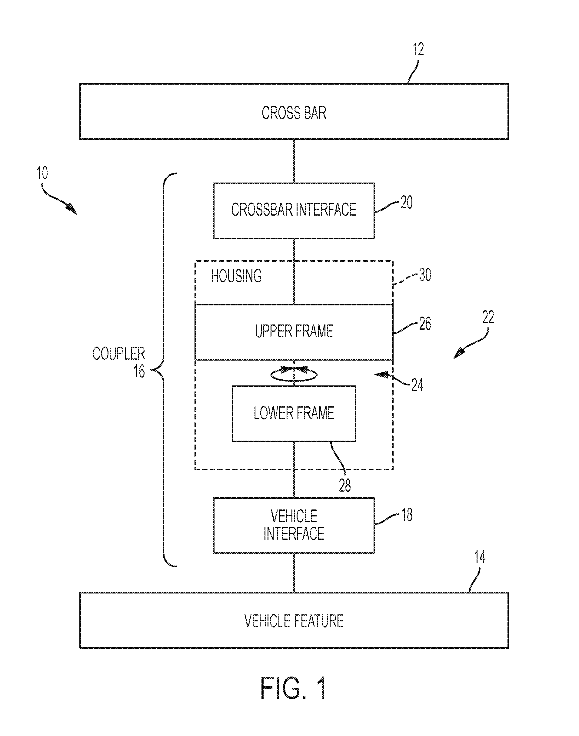
In general, and with reference to FIG. 1, a vehicle roof rack system 10 may include any suitable combination of components configured to provide a selected crossbar securely affixed to a vehicle rooftop. The crossbar is supported at either end by a pair of supports having features that facilitate attachment to corresponding feature(s) on the specific vehicle. The crossbar supports may also be referred to as towers, feet, or mounts, and are referred to herein as couplers and/or coupler assemblies. A versatile and efficient system may be provided to fit a selected crossbar to the wide range of vehicle rooftops present in the marketplace.
Accordingly, roof rack system 10 may include one or more types of crossbars 12 suitable for use on a range of vehicles. Each type of crossbar 12 may include any suitable crossbar configured to be mounted transverse to the long axis of a vehicle, across a rooftop, and to support loads placed thereon. For example, a crossbar 12 may support a bicycle carrier, ski carrier, kayak carrier, and the like. Crossbars are typically mounted on a vehicle in pairs, such that a forward and an aft crossbar are present on the vehicle for proper load carrying. Crossbars 12 may have any suitable cross section, such as round, square, teardrop, aerodynamic, and/or any other suitable shape or combination of shapes.
Crossbars 12 are supported by attaching or fastening each of the crossbars to one or more specific vehicle features 14. Vehicles come in many shapes and sizes, with a corresponding array of roof topologies. Vehicle features 14, to which the crossbars may be attached, can include raised rails running along lateral sides of a rooftop, flush rails with no space between the rails and the roof, channels or hard points on the roof, side edges or gutters of a naked roof, and/or the like.
To fasten the outboard ends of the crossbars to features 14, system 10 may include one or more couplers 16, also referred to as supports, towers, feet, or mounts, as mentioned above. Each coupler 16 may include any suitable vehicle interface 18 configured to attach, clamp, and/or removably connect to one or more vehicle features 14. Each coupler 16 may also include any suitable crossbar interface 20 configured to provide an attachment point or mount for a crossbar 12.
In some examples, crossbar interface 20 may include an interface for connecting a variety of crossbars. For example, crossbar interface 20 may include a threaded bolt protruding upward from support 16. Each specific crossbar 12 may include or be associated with a bar connector (also referred to as an adapter) configured to provide a crossbar-specific bar clamp when combined with a bar seat.
The bar clamp may be used to removably and securely attach crossbar 12 to coupler 16. For example, the bar connector may comprise a movable capturing portion configured to secure the crossbar against the seat portion. Accordingly, crossbar interface 20 of coupler 16 includes a clamp actuator configured to tighten, draw together, or otherwise cause the crossbar clamp to securingly engage the crossbar. The bar clamp actuator may include a manual actuator or manual actuating mechanism. Suitable bar clamps and actuators are described, for example, in U.S. patent application Ser. No. 15/167,774, the entirety of which is hereby incorporated herein for all purposes.
In some examples, coupler 16 may include a body or body portion 22 providing structural and/or other functional aspects of the coupler, e.g., locking devices, environmental, aesthetic, and/or aerodynamic outer housing features, internal support structure, etc. Vehicle interface 18 and/or crossbar interface 20 may be attached, unitary with, and/or coupled to coupler body portion 22. Alternatively or additionally, crossbar interface 20 and vehicle interface 18 may be coupled to each other.
For some vehicles and/or vehicle features, the vehicle roof and/or vehicle features 14 are angled. In these examples, installing crossbar 12 with its long axis at a right angle to the longitudinal axis of the vehicle will cause crossbar 12 to be at an acute or obtuse toe angle with respect to vehicle features 14. Accordingly, coupler 16 may include an adjustable toe angle mechanism 24 that allows vehicle interface 18 to be oriented differently, toe-wise, than crossbar interface 20.
Toe angle mechanism 24 may include any suitable structures configured to be rotated around a substantially vertical axis, such that a first of the structures is at a first toe angle and a second of the structures is at a second toe angle. For example, mechanism 24 may include an upper frame 26 of coupler body 22 pivotably coupled to a lower frame 28 of coupler body 22. An outer housing 30 of the coupler may be attached to one of the frames. In some examples, the housing is attached such that the housing rotates in tandem with one frame and rotates around the other frame. In some examples, the housing is attached such that the housing remains stationary while the other frame rotates within the housing. The lower frame may be described as stationary, because of its attachment (through the vehicle interface) to the vehicle (i.e., the larger of the two objects being coupled). However, either frame may be described as stationary and/or rotating with respect to the other frame, depending on the situation. In some examples, the upper and lower frame are securable in a plurality of toe orientations (e.g., continuous or discrete orientations).
Vehicle interface 18 may include any suitable structure and/or device configured to removably attach to a given vehicle feature (or features) 14. For example, vehicle interface 18 may include a clamp, hook, bolt, clip, strap, and/or the like, and/or any combination of these. To provide an efficient and versatile system, a selected number of vehicle interface types may be provided, some having modifiable or selectable components for further customization. Specific examples of vehicle interfaces 18 are mentioned below, such as in the discussion regarding FIG. 15.
Accordingly, system 10 may allow a user to choose a crossbar 12, select a coupler 16 having a vehicle interface 18 appropriate for attachment to vehicle feature 14 of the user's vehicle, and clamp the crossbar to the support using a corresponding bar connector and bar seat.
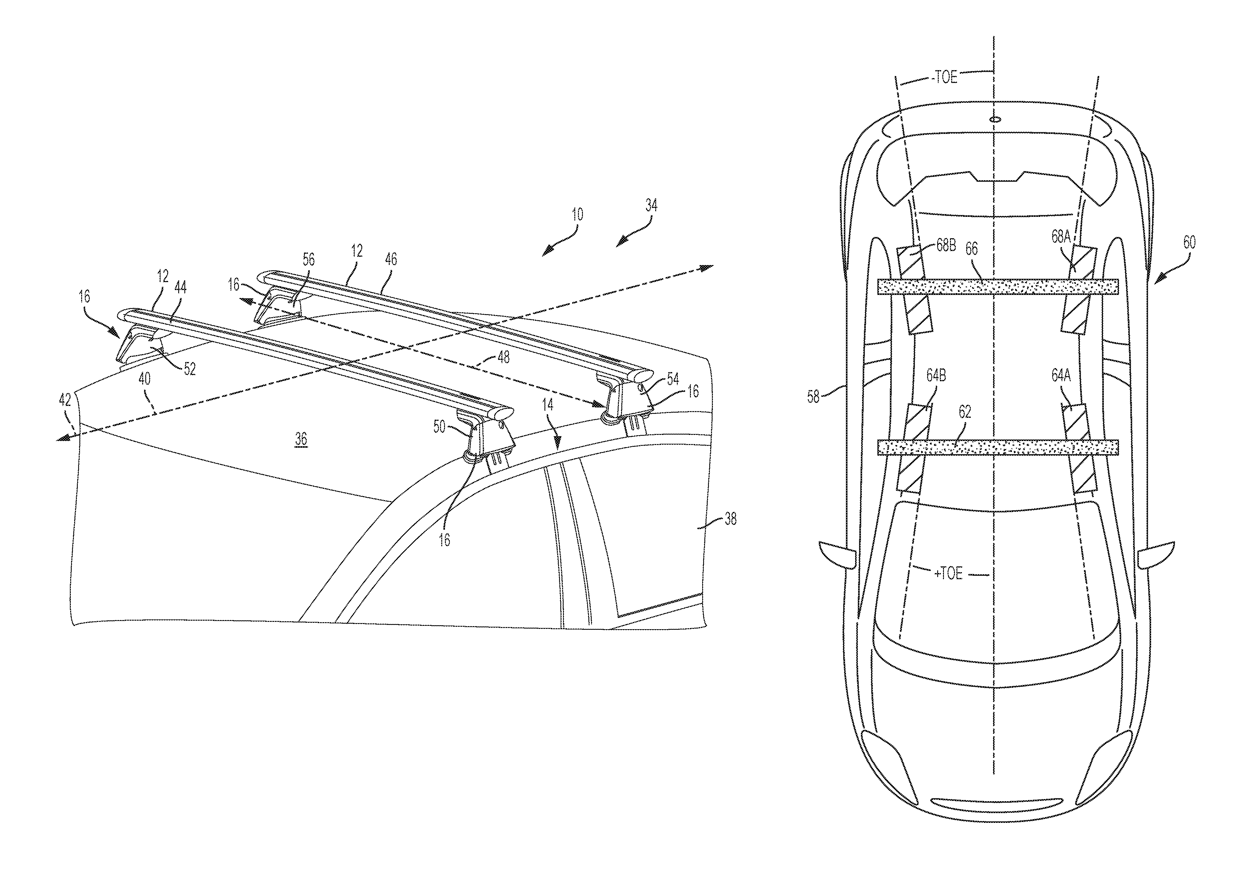
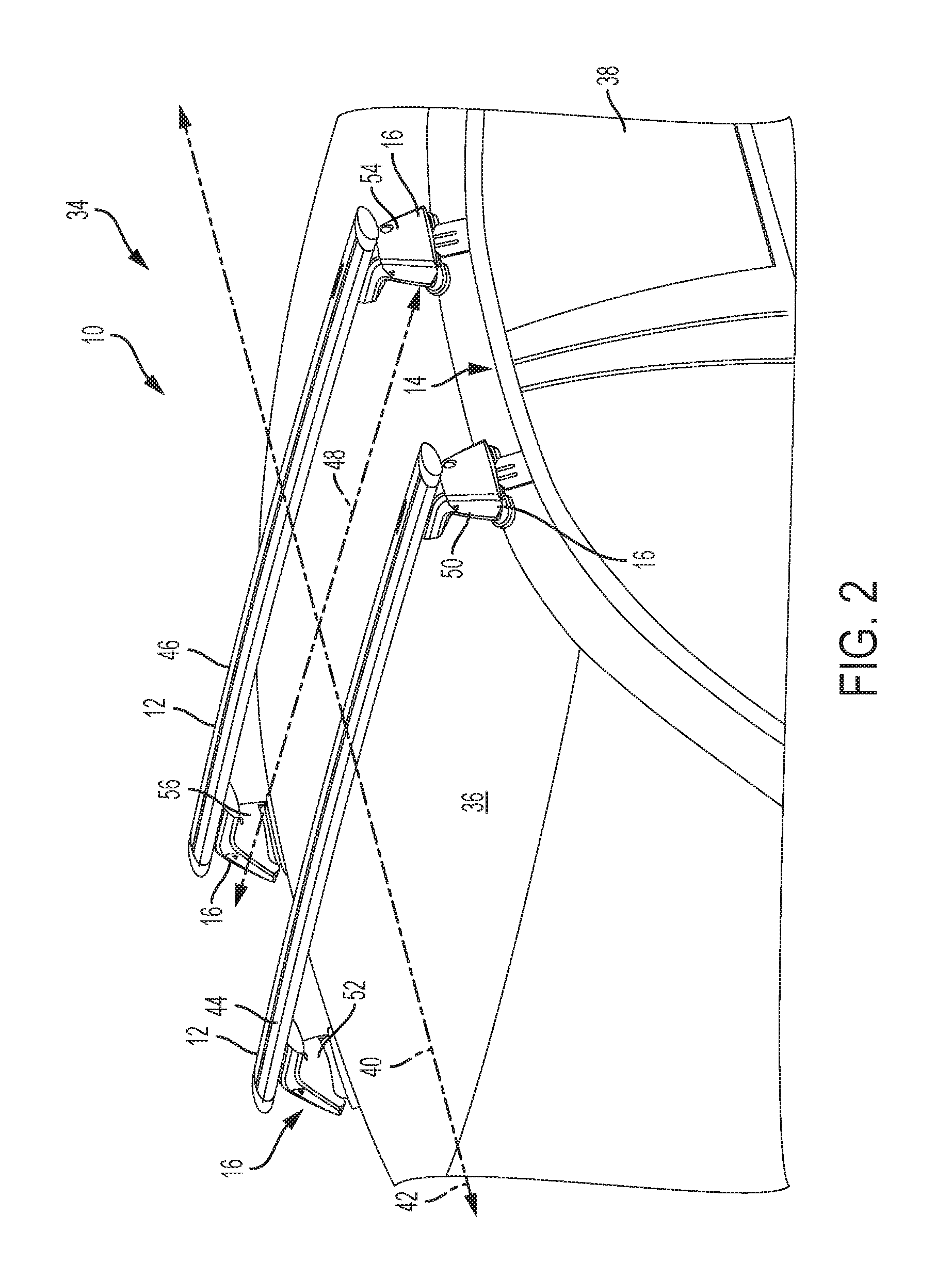
Turning to FIG. 2, a roof rack 34 is depicted, attached to an illustrative roof 36 of a vehicle 38. Roof rack 34 is a selected example of roof rack 10, described above. Accordingly, similar components may be labeled with similar reference numbers. Rack 34 may be used for carrying cargo and/or cargo-specific accessories on top of vehicle 38. Vehicle 38 has an longitudinal or central axis 46 generally coinciding with (e.g., running parallel to) a direction of vehicular travel 42.
Rack 34 includes a pair of crossbars 44 and 46 having aerodynamic shapes and attached to vehicle roof 36. Each crossbar is supported and mounted on vehicle 38 by a respective pair of couplers configured to mount the crossbar on top of the vehicle with the crossbar substantially perpendicular to longitudinal axis 40. Accordingly, crossbars 44 and 46 are substantially parallel to each other and oriented across a width of the vehicle roof, as generally indicated by a lateral axis 48 in FIG. 2. Crossbar 44 is mounted on top of the vehicle by couplers 50 and 52, and crossbar 46 is mounted on top of the vehicle using couplers 54 and 56. In this example, couplers 50, 52, 54, 56 have an adjustable clip style of vehicle interface configured to clamp onto side edges or gutters of the vehicle roof. Other styles may be suitable, and other vehicle features may be present.
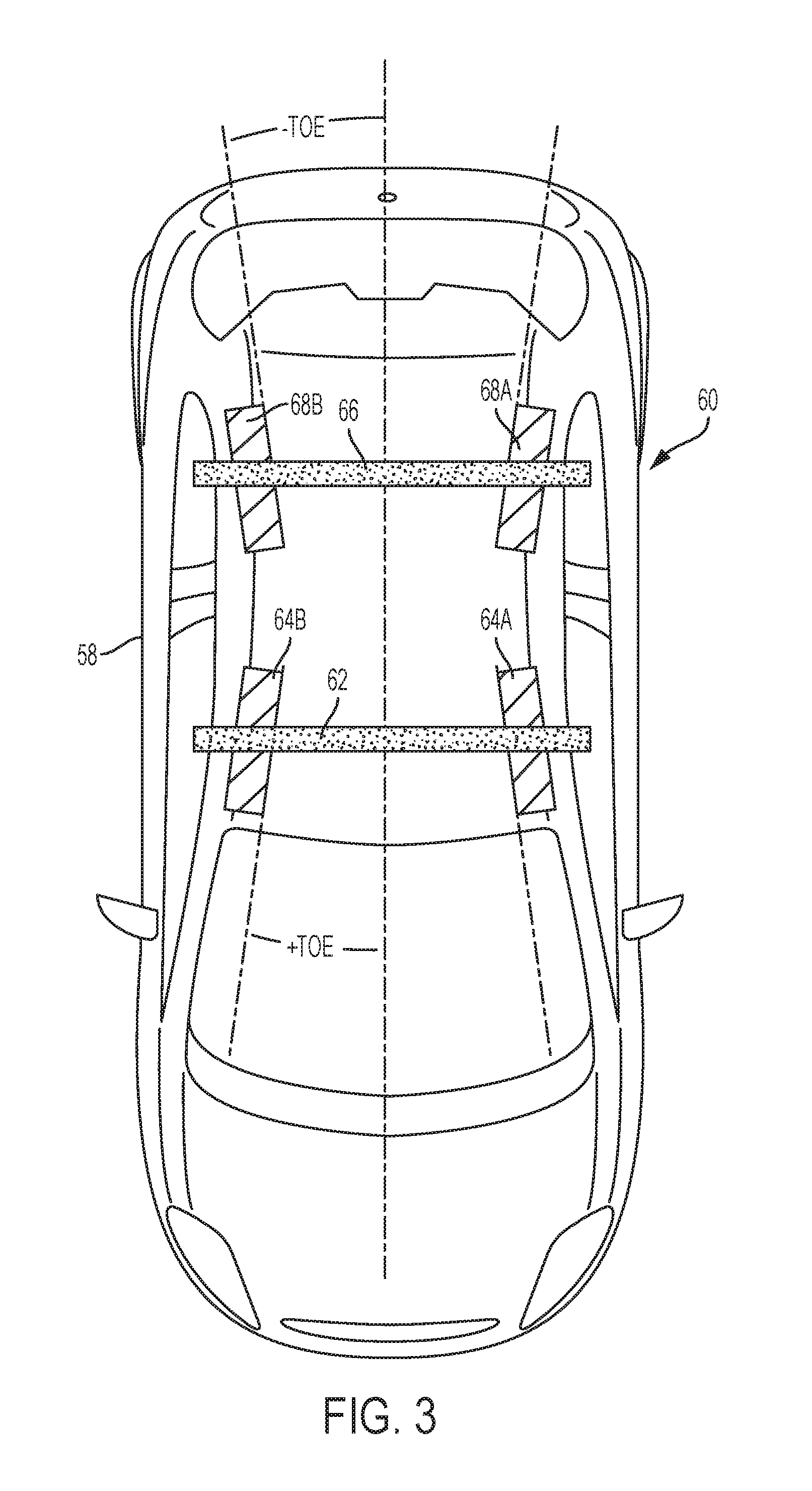
FIG. 3 is a schematic top view of a vehicle 58 having a rack 60 mounted on its roof. Rack 60 includes a forward crossbar 62 mounted to vehicle 58 by couplers 64A and 64B, and an aft crossbar 66 mounted to vehicle 58 by couplers 68A and 68B. As depicted in FIG. 3, crossbars 62 and 66 are mounted across the vehicle at a right angle (i.e., orthogonal) to the longitudinal axis of vehicle 58. However, due to the generally hourglass shape of the roof of vehicle 58, the couplers all have non-neutral toe angles. In other words, to attach to the side of the roof, a lower portion of the coupler must be rotated into alignment with the local roof edge, while an upper portion of the coupler remains aligned with the crossbar.
Examples, Components, and Alternatives
The following sections describe selected aspects of exemplary adjustable-toe couplers, as well as related systems and/or methods. The examples in these sections are intended for illustration and should not be interpreted as limiting the entire scope of the present disclosure. Each section may include one or more distinct inventions, and/or contextual or related information, function, and/or structure.
Schematic Example
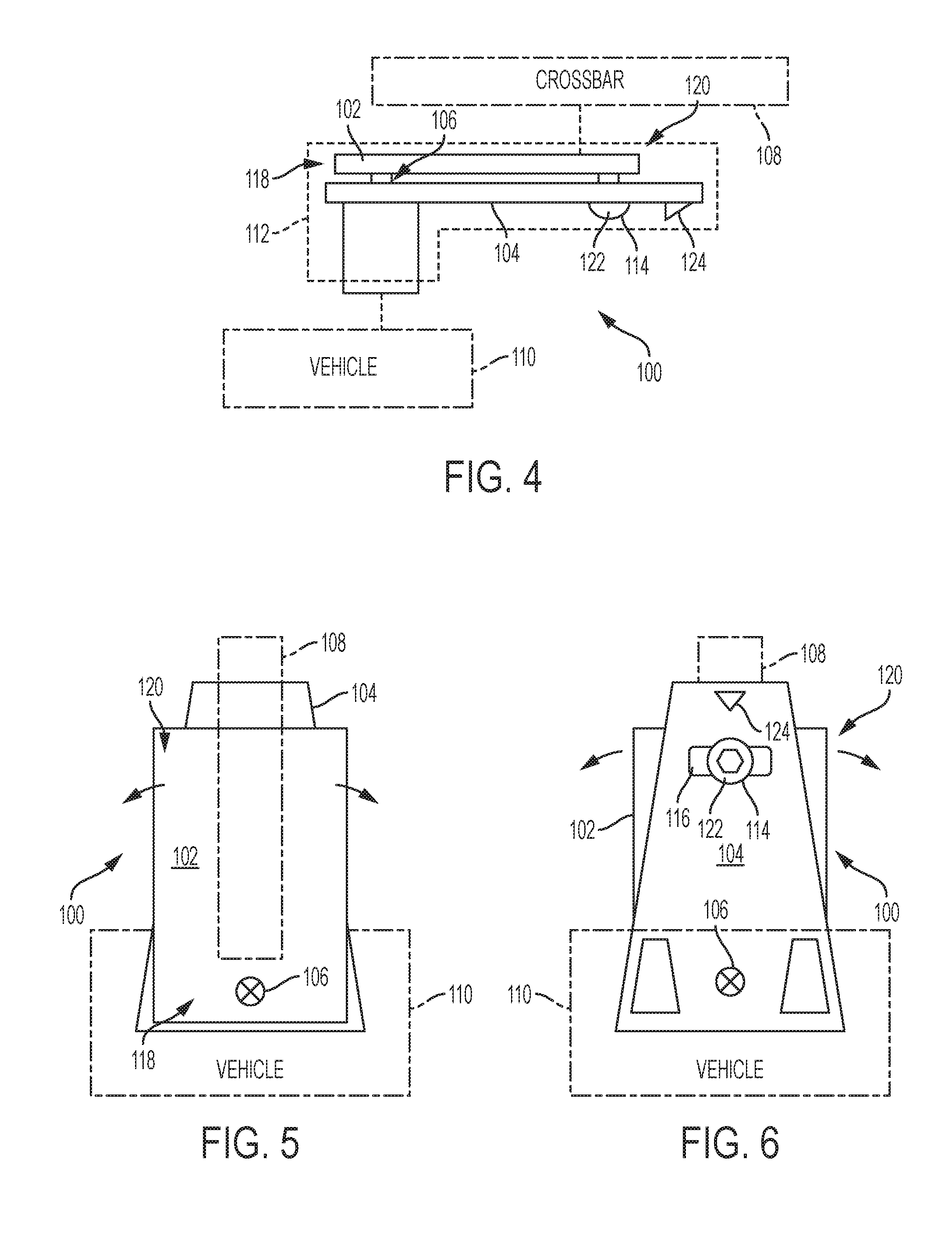
As shown schematically in FIGS. 4-6, this section describes an illustrative crossbar-to-vehicle coupler assembly 100 having an adjustable toe angle. Coupler assembly 100 (also referred to as coupler 100) is an example of coupler 16, described above.
FIG. 4 is a forward (or aft) side elevation view of coupler 100. FIG. 5 is an overhead plan view of coupler 100, and FIG. 6 is a bottom plan view of coupler 100.
As schematically indicated in FIGS. 4-6, the body of coupler 100 includes a first (e.g., upper) frame portion 102 pivotably attached to a second (e.g., lower) frame portion 104 at a pivot joint 106. The first and second frame portions are configured to pivot around a substantially vertical pivot axis (i.e., at joint 106). A crossbar 108 may be clamped or otherwise fixed (e.g., indirectly) to first frame portion 102. Furthermore, second frame portion 104 may be clamped or otherwise fixed (e.g., indirectly) to a vehicle feature 110. Accordingly, a toe angle of crossbar 108 can be adjusted relative to vehicle feature 110 by pivoting first frame portion 102 relative to second frame portion 104. Said another way, a toe angle of the coupler can be adjusted to accommodate the situation where the vehicle feature and crossbar are not situated at a right angle. The toe angle may be adjustable intra-coupler, as in this example, such that the first and second frame portions are rotated about the pivot axis with respect to each other (i.e., within the coupler itself).
Coupler 100 may include additional components and features not shown in FIGS. 4-6. For example, coupler 100 may include one or more clamps, interfaces, housings, etc., such as the coupler components described in the Overview section above. For example, an outer housing 112 is shown schematically in FIG. 4. Housing 112 may be coupled to frame portion 102 and/or frame portion 104. In some examples, housing 112 may rotate with the upper frame portion. In some examples, housing 112 may remain stationary while one or both frame portions rotate within the housing.
First frame portion 102 and second frame portion 104 may each include any suitable structural frames, frameworks, struts, plates, trusses, mounts, and/or the like, or any combination of these, for providing structural integrity and load-bearing support, as well as attachment points for other coupler components.
As shown in FIGS. 4 and 6, relative pivoting or rotation of the frame portions may be limited to a certain range. A pin or bolt 114 may protrude from first frame portion 106 and pass through a slot or elongate opening 116 in second frame portion 104. First frame portion 102 may have a pivoting end portion 118 (also referred to as a distal end) and a free end portion 120 (also referred to as a distal end). Bolt 114 may be threaded into a lower surface of free end portion 120, such that bolt 114 first passes through slot 116 in second frame portion 104. Slot 116 limits how far the upper frame portion can pivot relative to the lower frame portion, because rotation will be arrested when bolt 114 reaches either end of the slot. A head 122 of bolt 114 may facilitate tightening of the bolt, such that head 122 abuts the lower surface of the second frame portion, thereby clamping (i.e., securing) the frame portions together in a selected orientation.
Pivot joint 106 may include any suitable joint configured to pivot, rotate, or hinge around a substantially vertical axis. Pivoting may be free-rotating, or may be biased, such as by a spring or other self-centering mechanism. A detent mechanism may be integrated into pivot joint 106, such that selected rotational orientations are mechanically preferred. In other examples, a detent mechanism may be included in free end portion 120.
A projecting member 124 may be included in a free end of lower frame portion 104. Projecting member 124 may include any suitable protrusion configured to facilitate indication and/or selection of the toe angle. For example, member 124 may indicate a selected toe angle when compared to an aspect of outer housing 112. In some examples, member 124 may be used to manually reposition the housings and/or as part of the detent mechanism, if included.
Illustrative Crossbar-to-Vehicle Coupler
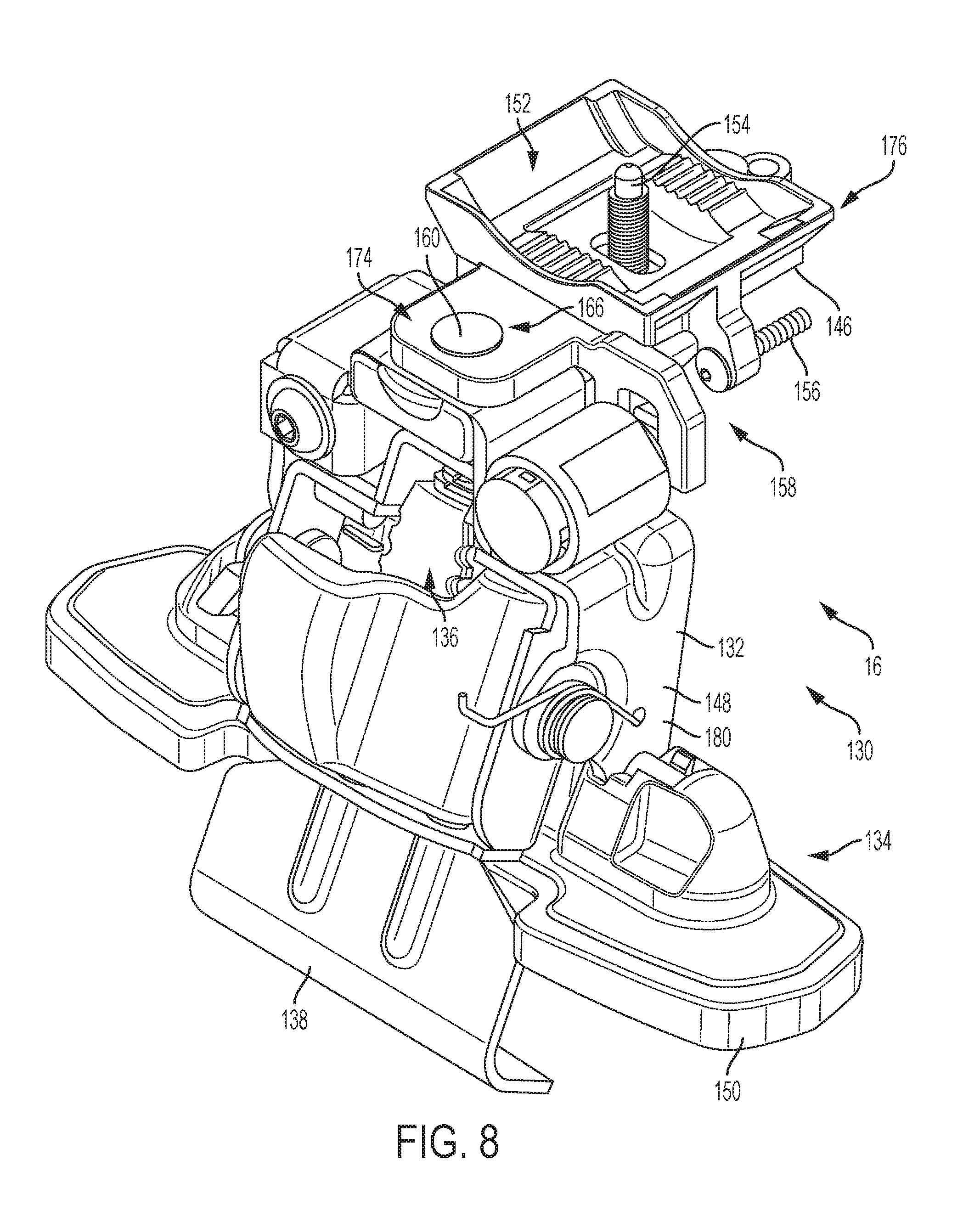
As shown in FIGS. 7-12, this section describes an illustrative crossbar-to-vehicle coupler 130 having an adjustable toe angle mechanism. Coupler 130 is substantially similar to couplers 64A, 64B, 68A, 68B shown in FIG. 2, and is a specific example of coupler 16 and coupler 100, described above.
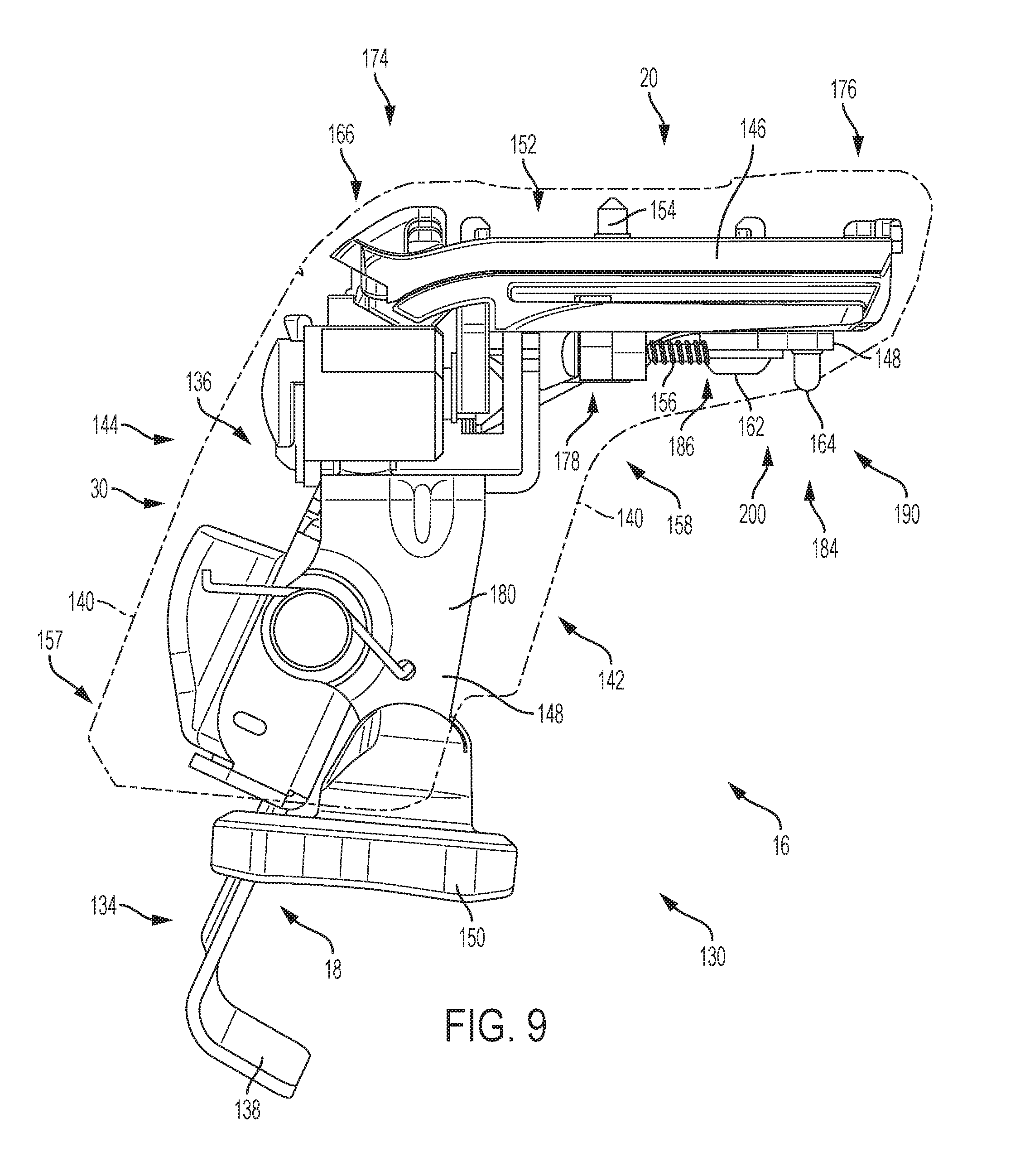
FIGS. 7 and 8 are oblique isometric views of crossbar-to-vehicle coupler 130 with the interchangeable crossbar clamp removed for simplicity. FIG. 7 is a view of the assembled coupler, while FIG. 8 shows the coupler with an outer housing portion removed to reveal internal components. FIG. 9 is a side elevation view of coupler 130, showing the outer housing in phantom lines.
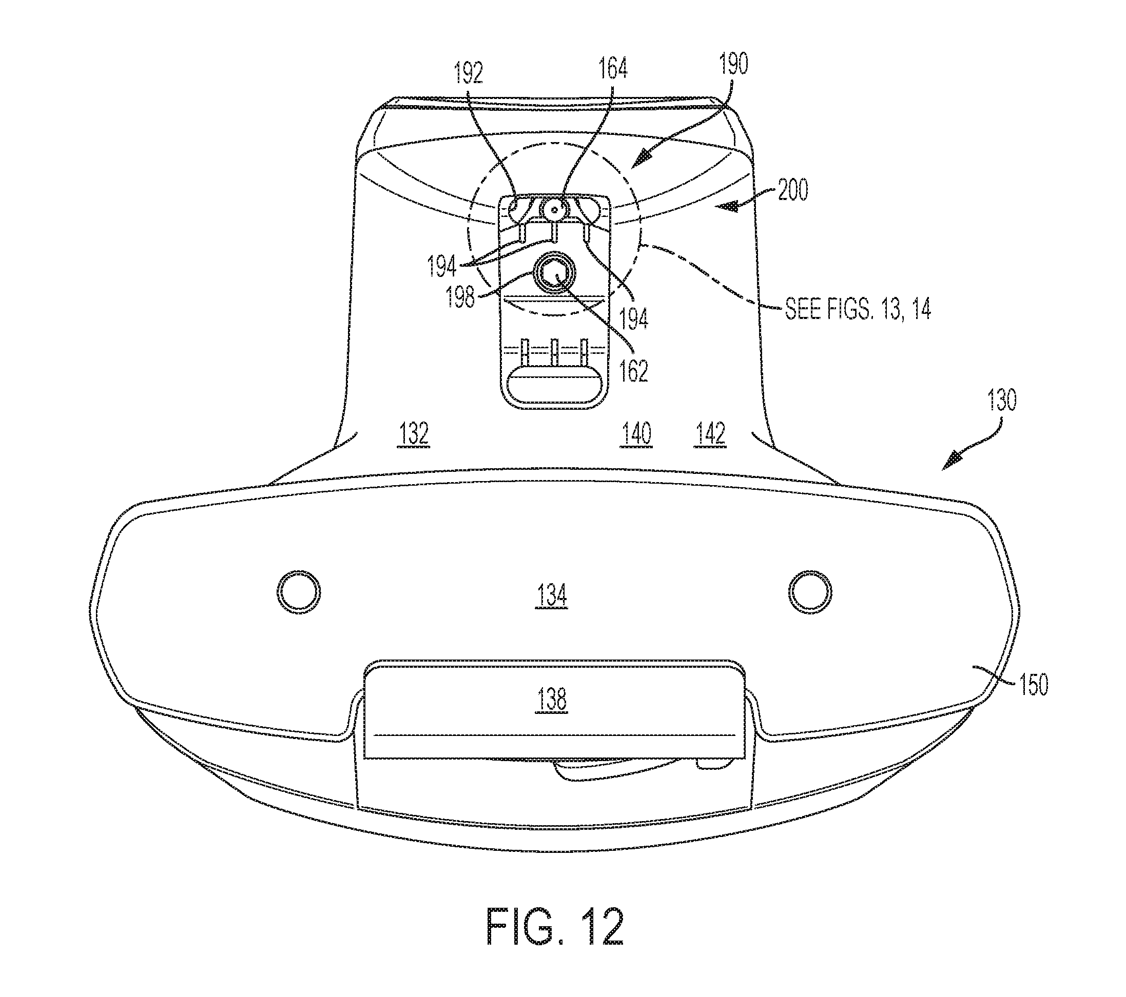
Coupler 130 includes a coupler body 132, a base portion 134, a clip retention and adjustment mechanism or assembly 136, and a clip 138. Coupler body 132 may include an outer housing 140 comprising an inboard cover 142 and a removable outboard cover 144, an upper (e.g., first) frame 146, and a lower (e.g., second) frame 148. Together, the inboard and outboard covers may protect portions of coupler 130 against the environment, may selectively prevent access to other components of the coupler, and may present an aesthetic and/or aerodynamic outer surface. The upper and lower frames may provide structural support for the coupling assembly. As described further below, the upper and lower frames may be pivotally/pivotably mounted to one another, thereby facilitating a toe angle adjustment of the coupler assembly, as described above in reference to FIGS. 4-6 and elsewhere.
Base portion 134 may be hingedly coupled to body 132 (e.g., pivotable around an axis parallel to the vehicle roof), and may include a base pad 150 configured to abut or otherwise make supportive and/or bracing contact with the roof of the vehicle. Base pad 150 may be constructed of a resilient material, such as rubber, and may prevent damage to the roof. The base pad may be one of an interchangeable set of base pads, with each base pad configured to be coupled to the base portion and configured to be used on the roof of a particular vehicle or set of vehicles. With clip 138, base portion 134 comprises vehicle interface 18 for coupler 130.
Clip retention and adjustment mechanism 136 includes components and structures configured to facilitate adjustment of clip 138 relative to body 132, such that clip 138 and base portion 134 cooperatively clamp the coupler onto the vehicle roof. Additional details and examples of coupler 130, including components of the clip retention and adjustment mechanism, are described in U.S. application Ser. No. 15/170,326, the entirety of which is hereby incorporated herein, for all purposes.
Upper frame 146 includes an upper support surface 152 and clamp interface bolt 154. A crossbar clamp (not shown) may be attached to coupler 130 by interface bolt 154. A portion of the clamp rests on upper support surface 152, and can be selectively pivoted on curved, toothed portions of the support surface, e.g., in discrete orientations, to effect different pitch angles of the crossbar. The clamp may be actuated by manipulation of interface bolt 154, e.g., by exerting a downward force on and/or using bolt 154. Examples of suitable clamps, clamp actuators, and related systems and methods may be found in U.S. patent application Ser. Nos. 15/172,043 and 15/167,774.
Outer housing 140 is fastened to upper frame 146 by a pair of screws or bolts 156. This arrangement has at least two results. First, outer housing 140 will pivot with (or stay stationary with) the upper frame, relative to the lower frame. Outer housing 140 and lower frame 148 are therefore configured to move substantially independently, such that the outer housing and lower frame do not interfere with each other over a range of toe adjustments. In this regard, in some examples (e.g., as shown in FIGS. 7 and 9), outer housing 140 may form a skirt 157 laterally surrounding part of the lower frame. Second, relative motion between the lower frame and the outer housing may be utilized for additional functionality, e.g., by taking advantage of the fact that the outer housing effectively functions as an extension of the upper frame. For example, a portion of lower frame 148 may mechanically interface with outer housing 140, such as to provide position indication and/or a detent feature (as described below).
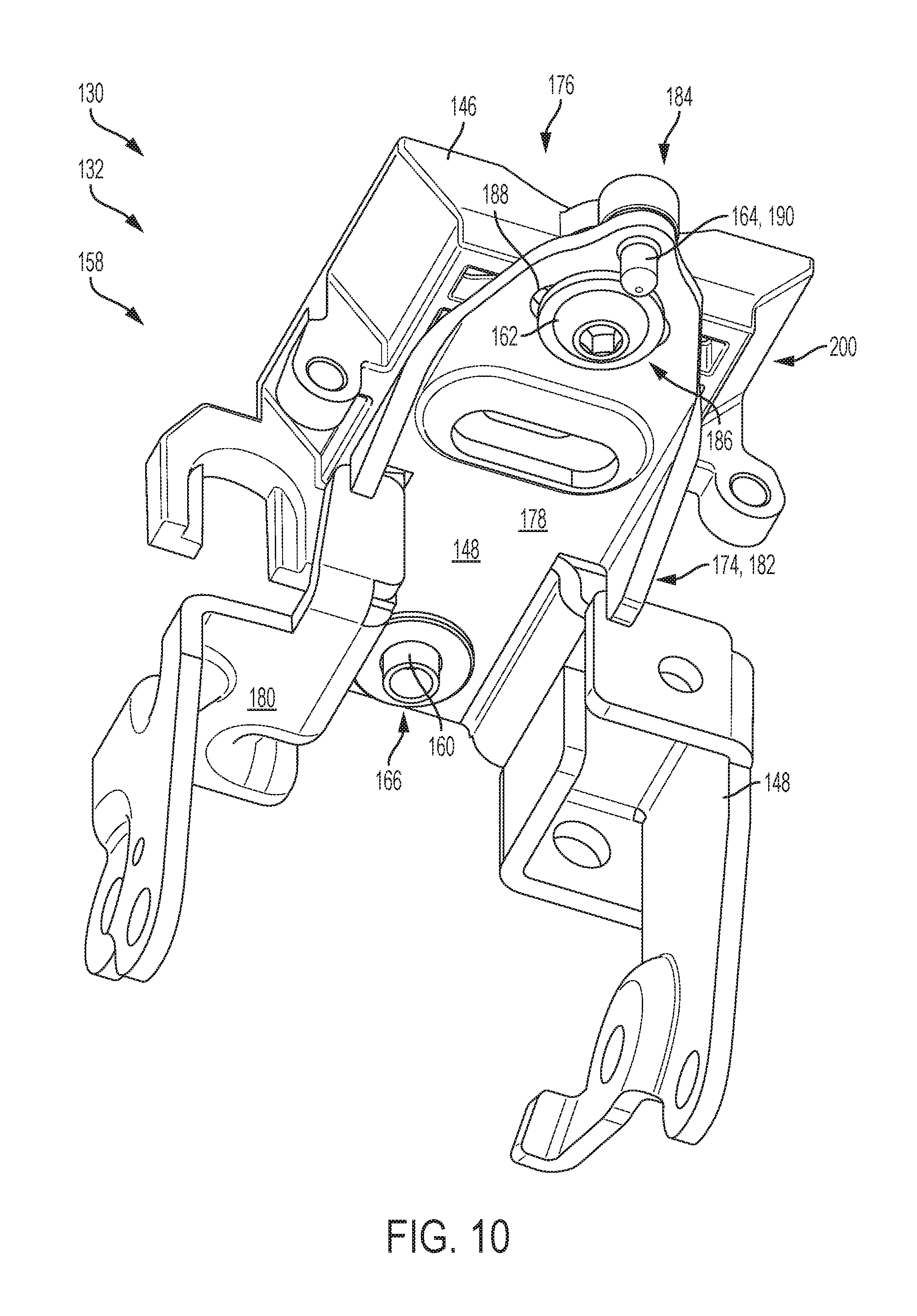
A toe adjustment mechanism 158 of coupler 130 comprises upper frame 146 and lower frame 148, as well as a pivot axle 160, an adjustment bolt 162, and an indication and detent member 164. Toe adjustment mechanism 158 is an example of adjustable toe angle mechanism 24, described above. FIGS. 10 and 11 are views that isolate the toe adjustment mechanism of coupler 130, showing relationships between related components and aspects of the frames. FIG. 9 is a lower oblique isometric view of toe adjustment mechanism 158. FIG. 10 is an upper oblique, isometric, exploded view of toe adjustment mechanism 158.
As depicted in FIGS. 10-11, upper frame 146 is pivotably attached to lower frame 148 at a pivot joint 166 using pivot axle 160, such that the upper and lower frames are mutually rotatable around a substantially vertical axis 168 (e.g., an axis perpendicular to the long axis of the crossbar, when installed). Pivot axle 160 may include any suitable structure configured to provide a pivot for the two frames, such as a shaft, pin, axle, spindle, rod, and/or the like. Pivot axle 160 may comprise a bearing surface. In this example, axle 160 comprises a metal rivet, the shaft of which passes through a pair of aligned apertures 170 and 172 in the upper and lower frames, respectively.
Upper frame 146 is a rigid, plate-like structure having a pivot (or proximal) end portion 174 that includes pivot joint 166, and a free (or distal) end portion 146 that swings back and forth. As described above, upper frame 146 includes upper support surface 152.
Lower frame 148 is a rigid structure having a plate-like portion 178 that generally faces and parallels upper frame 146 and a leg portion 180 that depends from portion 178 to add height to the coupler body (e.g., to raise the crossbar above the vehicle roof). As with the upper frame, portion 178 of lower frame 148 has a pivot (or proximal) end portion 182 that includes pivot joint 166, and a free (or distal) end portion 184 that swings back and forth. Leg portion 180, being generally disposed on an opposite side of pivot joint 166 from the distal end, may swing in an opposite direction as compared to distal end 184. Leg portion 180 may include a plurality of legs, such as two legs.
Rotation of the upper and lower frames relative to each other may be secured at a selected angle of rotation, by a frame securement mechanism 186. Frame securement mechanism 186 may be disposed at the distal end portions of the frames. For example, as shown in FIGS. 10 and 11, adjustment bolt 162 (also referred to as a screw or threaded member) may project from the upper frame portion through an elongated slot or hole 188 in the lower frame portion. The frame portions may be secured from rotating relative to each other by securing or clamping the two frames together. For example, bolt 162 may have a released (e.g., loosened) configuration, in which upper frame 146 and lower frame 148 are free to rotate, and a tightened configuration, in which the two frames are fixed together. In the released configuration, the threaded member is allowed to slide back and forth in elongated hole 188.
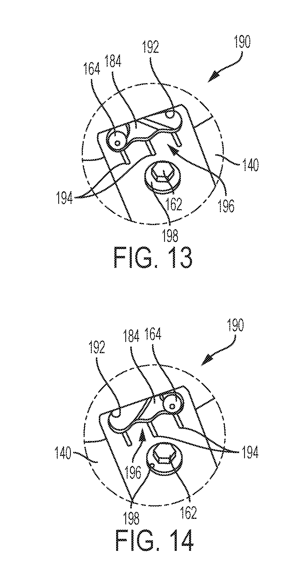
With continuing reference to FIGS. 10-11, and now with reference to FIGS. 12-14, coupler 130 may include a detent interface 190 between outer housing 140 and toe angle adjustment mechanism 158. FIG. 12 is a bottom view of coupler 130, with the outer housing installed. FIGS. 13 and 14 are partial magnified views of detent interface 190, showing the interface in different configurations, as described below.
Detent interface 190 may include indication and detent member 164, which is another elongate member projecting from free end 176 of the lower frame. Member 164 is shown in this example as a partially threaded screw installed in the lower frame. In some examples, member 164 may be unitary with or otherwise attached to lower frame 148. Member 164 may project downward from the lower frame through a shaped aperture 192 in the outer housing. Because outer housing 140 is fixedly coupled to upper frame 146, member 164 will change position within the aperture as the frames pivot at joint 166. Accordingly, the position of member 164 may be utilized to indicate the toe angle of the frame(s). Indicia 194 may be provided on housing 140 adjacent to shaped aperture 192, as best seen in FIG. 12.
Shaped aperture 192 may include a scalloped edge 196, such that member 164 laterally abuts the scalloped edge. This arrangement results in a detent feature, as pivoting of the frames will cause member 164 to bump from dip to dip in the scalloped edge, thereby creating a plurality of discrete positions corresponding to different orientations (i.e., toe angles) that the user can choose from. In this example, three such dips are present, resulting in three discrete orientations or angles and three different indications in the detent interface, as shown in FIGS. 12-14. Once a toe angle is selected, the user can secure the frames to each other using frame securement mechanism 186. For example, an access hole 196 in outer housing 140 may allow access to a head of bolt 162 to secure the selected angle (or release the frames for further adjustment).
Rotation of the frames may be limited (e.g., to a range of angles) by a mechanical stop 200. Mechanical stop 200 may include any suitable structures configured to arrest rotation of the upper and/or lower frames relative to each other. Mechanical stop 200 may include a member projecting from one of the frame portions through an elongated hole, such that rotation is arrested when the projecting member reaches an end of the elongated hole. In some examples, mechanical stop 200 may include adjustment bolt 162 protruding from upper frame 146 through elongated hole 188, such that pivoting of the frames is arrested when bolt 162 reaches either end of the hole. In some examples, mechanical stop 200 may include detent member 164 protruding from lower frame 148 through shaped aperture 192 in outer housing 140, such that pivoting of the frames is arrested when member 164 reaches either end of the aperture. Other suitable mechanical stops may be provided.
Illustrative Crossbar-Coupler Combinations
As shown in FIG. 15, this section describes various suitable combinations of an illustrative toe adjustment mechanism with different crossbars, crossbar clamps, and coupler styles. The toe adjustment mechanism described in this section is a schematic example of adjustable toe angle mechanism 24 and toe angle adjustment mechanism 158, described above.
A toe adjustment mechanism 300 is shown schematically in FIG. 15, and represents any example of toe adjustment mechanism 24 according to the present teachings (e.g., toe adjustment mechanism 158). In this type of toe adjustment mechanism, a first frame portion is pivotably coupled to a second frame portion, and a detent interface between an outer housing of the coupler and the toe adjustment mechanism, is configured to selectively permit rotation of the first frame portion relative to the second frame portion among a plurality of discrete toe angles.
Toe adjustment mechanism 300 is versatile, in that toe adjustment mechanism 300 may be utilized or incorporated into various couplers, such as couplers 302, 304, 306, 308 shown in FIG. 15. Although four such couplers are shown in FIG. 15 and described below, it should be understood that inclusion of toe adjustment mechanism 300 is optional for any given coupler, and that more or fewer couplers may be available for such inclusion.
As described above with respect to couplers 16, 100, and 130, a coupler according to the present teachings includes any suitable device configured to mount a crossbar to a vehicle feature. Accordingly, couplers 302, 304, 306, 308 each include a crossbar interface 20 comprising a selected crossbar clamp and actuator, as well as a vehicle interface 18 for clamping or otherwise connecting the coupler to a vehicle feature.
Specifically, coupler 302 is a strap-type coupler suitable for connecting the coupler to a raised rail feature of a vehicle. Raised rails generally include a pair of rails or bars each running parallel to the direction of vehicle travel and spaced above a respective lateral side of the rooftop. A strap 310 extends from a body 312 of this coupler, and is configured to pass under one of the raised rails while body 312 rests on top of the rail.
Coupler 304 is a fixed-point style of coupler, suitable for connecting to a base portion fixed to a vehicle rooftop. Retractable pins in vehicle interface portion 18 of coupler 304 extend into corresponding receptacles in the base (not pictured). An example of a coupler having this type of vehicle interface is described in U.S. Pat. No. 6,905,053, the entirety of which is hereby incorporated herein for all purposes.
Coupler 306 is a naked-roof style of coupler, similar to the couplers shown in FIG. 2, suitable for connecting the coupler to a gutter or other slot running along a side of the vehicle rooftop. An adjustable clip 314 and a base 316 for seating on the roof extend from a lower portion of a body 318 of coupler 306. Base 316 sits atop the vehicle roof, while clip 314 grabs onto the vehicle gutter (or the like).
Coupler 308 is a two-clip flush rail type of coupler. This style of coupler is suitable for connecting the coupler to a flush rail feature of a vehicle. Flush rails generally include a pair of rails or bars each running parallel to the direction of vehicle travel on respective lateral sides of the rooftop. In contrast with the raised rail, a flush rail abuts the vehicle roof such that no gap exists between the rail and the roof. A pair of clips 320 extend from a body 322 of coupler 308 to grasp the rail.
Various crossbars may be clamped to the various couplers, as indicated in FIG. 15. Suitable crossbars may include a round crossbar 324, an aerodynamic crossbar 326, and/or a slotted crossbar 328. As described above, each type of crossbar may be secured to the coupler by a respective crossbar clamp. Crossbar clamps according to the present teachings may include a bar connector and a bar seat. The bar seat sits on the upper support surface of the coupler, and the bar connector is attached to an actuator in the coupler. The bar connector engages the crossbar and the actuator pulls the connector and crossbar down onto the seat, securing the crossbar to the coupler. Specifically, a round crossbar clamp 330 may include a crossbar connector 332 comprising a round sleeve, and a crossbar seat 334 having a rounded seating surface. Similarly, an aero bar clamp 336 may include a crossbar connector 338 comprising an elongated sleeve, and a crossbar seat 340 having a seating surface that conforms to the lower surface of crossbar 326. Finally, a T-slot crossbar clamp 342 may include a T-shaped crossbar connector 344 for sliding into a bottom T-slot of crossbar 328, and a crossbar seat 346 for cradling the crossbar.
Further details regarding suitable crossbars, crossbar clamps, and related systems are disclosed in U.S. patent application Ser. No. 15/167,774, the entirety of which is hereby incorporated herein for all purposes.
Illustrative Method for Adjusting Toe Angle in a Coupler
This section describes steps of an illustrative method for attaching a crossbar to a vehicle; see FIG. 16. Aspects of adjustable toe angle couplers described above may be utilized in the method steps described below. Where appropriate, reference may be made to previously described components and systems that may be used in carrying out each step. These references are for illustration, and are not intended to limit the possible ways of carrying out any particular step of the method.
FIG. 16 is a flowchart illustrating steps performed in an illustrative method, and may not recite the complete process or all steps of the method. FIG. 16 depicts multiple steps of a method, generally indicated at 360, which may be performed in conjunction with selectable-toe couplers according to aspects of the present disclosure. Although various steps of method 360 are described below and depicted in FIG. 16, the steps need not necessarily all be performed, and in some cases may be performed in a different order than the order shown.
Step 362 includes securing a crossbar to a crossbar-to-vehicle coupler using a crossbar interface clamp of the coupler. The coupler comprising a body including an outer housing and a toe angle adjustment mechanism having a first frame portion pivotably coupled to a second frame portion. The crossbar interface clamp is fixedly coupled to the first frame portion and a vehicle interface is coupled to the second frame portion. In some examples, the outer housing of the coupler body may be fixedly coupled to only the first frame portion, i.e., not to the second frame portion, such that the housing rotates with the first frame portion. In some of these examples, the outer housing forms a skirt around the second frame portion, such that the outer housing rotates around the second frame portion.
Step 364 includes orienting the vehicle interface of the coupler to a selected toe angle relative to the crossbar by pivoting the second frame portion around a pivot axis normal to a long axis of the crossbar using a detent interface of the coupler. The detent interface comprises the outer housing and the toe angle adjustment mechanism, and is configured to selectively permit rotation of the first frame portion relative to the second frame portion among a plurality of discrete toe angles including the selected toe angle.
Orienting the vehicle interface of the coupler may include selecting an orientation of the vehicle interface such that a long axis of the crossbar is substantially perpendicular to a longitudinal axis of the vehicle.
Step 366 includes securing the vehicle interface of the coupler at the selected toe angle relative to the crossbar, by fixing the first frame portion relative to the second frame portion. Securing the vehicle interface at the selected toe angle may include securing (e.g., affixing, fastening, clamping, bolting) the first frame portion to the second frame portion.
Optional step 368 includes securing the coupler to a vehicle roof using the vehicle interface. This step may be performed at any suitable point in the process. In some examples, step 368 may be performed before step 364 and/or step 366.
Additional Examples
This section describes additional aspects and features of crossbar-to-vehicle couplers having adjustable toe angle features, and related methods, presented without limitation as a series of paragraphs, some or all of which may be alphanumerically designated for clarity and efficiency. Each of these paragraphs can be combined with one or more other paragraphs, and/or with disclosure from elsewhere in this application, including the materials incorporated by reference in the Cross-References, in any suitable manner. Some of the paragraphs below expressly refer to and further limit other paragraphs, providing without limitation examples of some of the suitable combinations.
A0. A rack for carrying cargo on top of a vehicle, the rack comprising:
a crossbar; and
a coupler configured to mount an end portion of the crossbar on top of a vehicle, the coupler including a body having a first frame portion fixedly coupled to the crossbar, a second frame portion connected to the first frame portion, and a substantially continuous outer housing at least partially surrounding the first and the second frame portions, the outer housing fixed to only the first frame portion or to only the second frame portion, and a vehicle interface coupled to the second frame portion of the body, the vehicle interface configured to attach the coupler to the top of the vehicle;
wherein the second frame portion is pivotable around a substantially vertical axis relative to the first frame portion to orient the vehicle interface at a plurality of different toe angles relative to the crossbar.
A1. The rack of A0, wherein pivoting of the second frame portion relative to the first frame portion is limited by a mechanical stop.
A2. The rack of A1, wherein the mechanical stop comprises a member projecting from the first frame portion through an elongated hole in the second frame portion, such that rotation is arrested when the projecting member reaches an end of the elongated hole.
A3. The rack of any of paragraphs A0 through A2, wherein the body of the coupler further comprises a frame securement mechanism configured to selectively prevent relative rotation between the first and second frame portions.
A4. The rack of A3, wherein the frame securement mechanism comprises a bolt having a released configuration, in which the first and second frame portions are free to rotate, and a tightened configuration, in which the first and second frame portions are fixed together.
A5. The rack of A3, the body of the coupler further comprising a mechanical stop limiting rotation of the first frame relative to the second frame.
A6. The rack of any of paragraphs A0 through A5, wherein the outer housing is fixed to only the first frame portion and laterally surrounds both the first frame portion and the second frame portion, such that the outer housing forms a skirt around the second frame portion and the vehicle interface protrudes from an opening of the skirt.
A7. The rack of any of paragraphs A0 through A6, wherein the outer housing comprises a selectively removable cover portion.
A8. The rack of any of paragraphs A0 through A7, wherein the vehicle interface includes an adjustable clip configured to hook onto an edge of the vehicle roof and a resilient base portion configured to abut the vehicle roof.
B0. A crossbar-to-vehicle coupler for mounting a cargo rack to a vehicle, the coupler comprising:
a body including an outer housing and a toe angle adjustment mechanism having a first frame portion pivotably coupled to a second frame portion;
a crossbar interface clamp coupled to the first frame portion, the crossbar interface clamp configured to releasably secure the coupler to a crossbar;
a vehicle interface coupled to the first frame portion, the vehicle interface configured to releasably secure the coupler to a vehicle feature; and
a detent interface between the outer housing and the toe angle adjustment mechanism, the detent interface configured to selectively permit rotation of the first frame portion relative to the second frame portion among a plurality of discrete toe angles.
B1. The coupler of B0, wherein the first frame portion is pivotable with respect to the second frame portion around a substantially vertical axis.
B2. The coupler of B1, wherein the first frame portion and the second frame portion share a pivot joint.
B3. The coupler of any of paragraphs B0 through B2, wherein the detent interface comprises a member protruding from the toe angle adjustment mechanism through a shaped aperture in the outer housing.
B4. The coupler of B3, wherein the member laterally abuts against a scalloped edge of the shaped aperture.
B5. The coupler of B3, wherein the member protrudes from the second frame portion.
B6. The coupler of B3, further comprising indicia adjacent the shaped aperture, the indicia corresponding to the plurality of discrete toe angles.
B6. The coupler of any of paragraphs B0 through B5, wherein the outer housing laterally surrounds the first frame portion and the second frame portion, the outer housing being fixedly coupled to only the first frame portion.
B7. The coupler of B6, wherein the outer housing forms a skirt around the second frame portion.
B8. The coupler of B7, wherein the outer housing comprises a removable cover portion.
B9. The coupler of any of paragraphs B0 through B8, wherein the vehicle interface includes an adjustable clip configured to hook onto an edge of the vehicle feature and a resilient base portion configured to abut the vehicle.
C0. A method for attaching a crossbar to a vehicle, the method comprising: securing a crossbar to a crossbar-to-vehicle coupler using a crossbar interface clamp of the coupler, the coupler comprising a body including an outer housing and a toe angle adjustment mechanism having a first frame portion pivotably coupled to a second frame portion, wherein the crossbar interface clamp is fixedly coupled to the first frame portion and a vehicle interface is coupled to the second frame portion;
orienting the vehicle interface of the coupler to a selected toe angle relative to the crossbar by pivoting the second frame portion around a pivot axis normal to a long axis of the crossbar using a detent interface of the coupler, the detent interface comprising the outer housing and the toe angle adjustment mechanism and configured to selectively permit rotation of the first frame portion relative to the second frame portion among a plurality of discrete toe angles including the selected toe angle; and
securing the vehicle interface of the coupler at the selected toe angle relative to the crossbar by fixing the first frame portion relative to the second frame portion.
C1. The method of C0, further including securing the coupler to a vehicle roof using the vehicle interface.
C2. The method of C0, wherein orienting the vehicle interface of the coupler includes selecting an orientation of the vehicle interface such that a long axis of the crossbar is substantially perpendicular to a longitudinal axis of the vehicle.
C3. The method of C2, further including securing the coupler to a vehicle roof using the vehicle interface, after orienting the vehicle interface.
C4. The method of any of paragraphs C0 through C3, wherein securing the vehicle interface at the selected toe angle includes securing the first frame portion to the second frame portion.
C5. The method of any of paragraphs C0 through C4, wherein the outer housing of the coupler body is fixedly coupled to only the first frame portion.
C6. The method of C5, wherein the outer housing forms a skirt around the second frame portion.
Advantages, Features, Benefits
The different embodiments and examples of the adjustable-toe couplers described herein provide several advantages over known solutions for attaching crossbars to vehicle rooftops. For example, illustrative embodiments and examples described herein allow a toe angle to be selected from a plurality of discrete toe angles, e.g., using a detent mechanism.
Additionally, and among other benefits, illustrative embodiments and examples described herein facilitate visual indication and/or securing of the selected toe angle from an accessible portion of the coupler.
Additionally, and among other benefits, illustrative embodiments and examples described herein include an outer housing that rotates with only one of the two frames while protecting both of the frames and other internal components of the coupler.
Additionally, and among other benefits, illustrative embodiments and examples described herein facilitate a useful and easily-incorporated mechanism for providing toe adjustment in various styles and types of couplers.
No known system or device can perform these functions. However, not all embodiments and examples described herein provide the same advantages or the same degree of advantage.
Conclusion
The disclosure set forth above may encompass multiple distinct examples with independent utility. Although each of these has been disclosed in its preferred form(s), the specific embodiments thereof as disclosed and illustrated herein are not to be considered in a limiting sense, because numerous variations are possible. To the extent that section headings are used within this disclosure, such headings are for organizational purposes only. The subject matter of the invention(s) includes all novel and nonobvious combinations and subcombinations of the various elements, features, functions, and/or properties disclosed herein. The following claims particularly point out certain combinations and subcombinations regarded as novel and nonobvious. Other combinations and subcombinations of features, functions, elements, and/or properties may be claimed in applications claiming priority from this or a related application. Such claims, whether broader, narrower, equal, or different in scope to the original claims, also are regarded as included within the subject matter of the present disclosure.
* * * * *
References
-
bike-racks-plus.com/Roof_Mounted_Bike_Racks_y.htm
-
rackattackportland.wordpress.com/2010/03/29another-hit-from-yakima-the-all-new-factory-compatible-frontloader-upright-bike-rack
-
carracks.blogspot.nl/2010/04/yakima-frontloader-upright-bike-rack.html
-
youtube.com/watch?v=cu8rHM90Rdw
-
firecall.yakima.com
-
yakima.com/shop/bike/roof/frontloader#pr-header-8002103
D00000
D00001
D00002
D00003
D00004
D00005
D00006
D00007
D00008
D00009
D00010
D00011
D00012

D00013
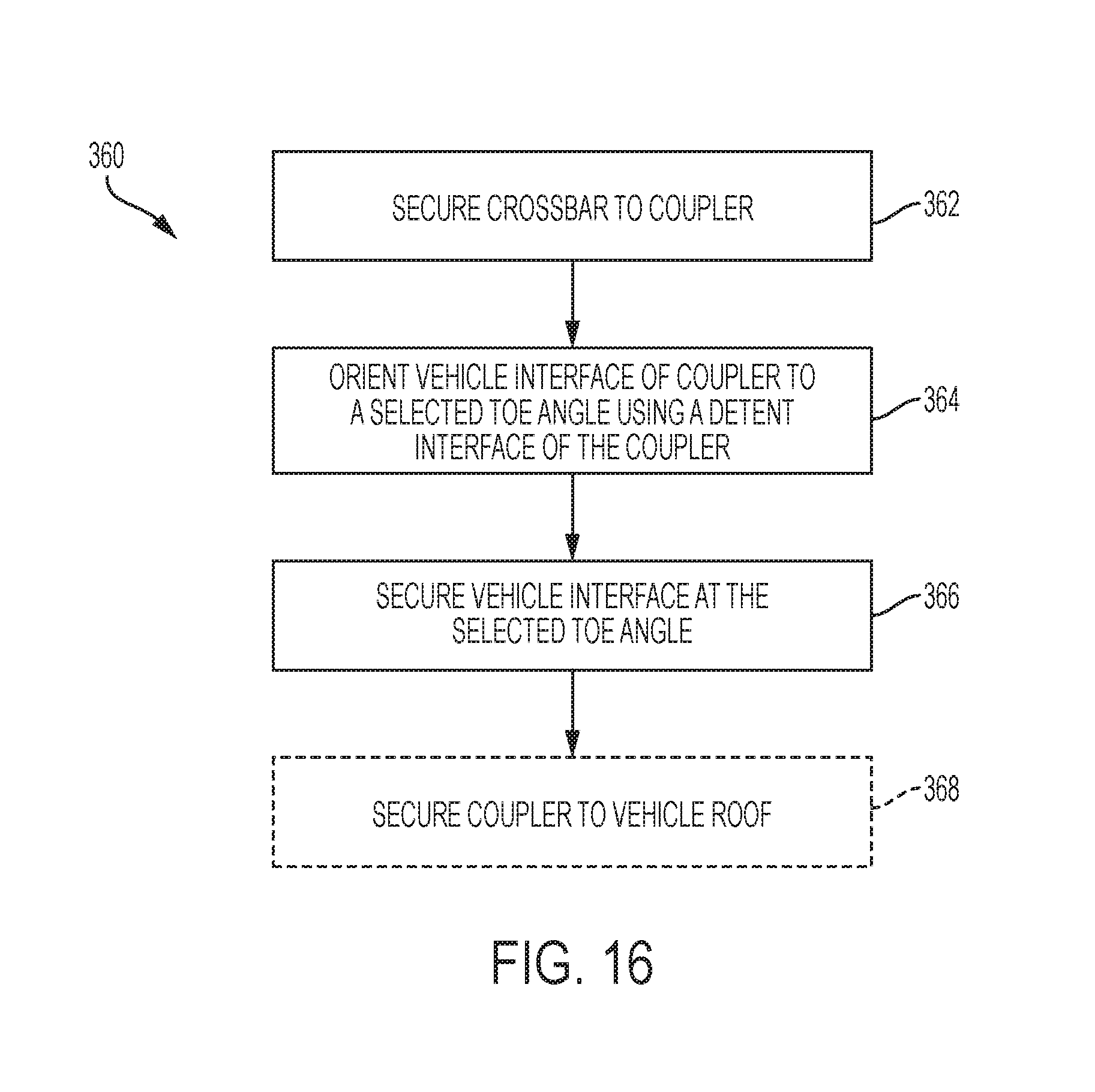
XML
uspto.report is an independent third-party trademark research tool that is not affiliated, endorsed, or sponsored by the United States Patent and Trademark Office (USPTO) or any other governmental organization. The information provided by uspto.report is based on publicly available data at the time of writing and is intended for informational purposes only.
While we strive to provide accurate and up-to-date information, we do not guarantee the accuracy, completeness, reliability, or suitability of the information displayed on this site. The use of this site is at your own risk. Any reliance you place on such information is therefore strictly at your own risk.
All official trademark data, including owner information, should be verified by visiting the official USPTO website at www.uspto.gov. This site is not intended to replace professional legal advice and should not be used as a substitute for consulting with a legal professional who is knowledgeable about trademark law.