Apparatus and method for separating and concentrating fluids containing multiple components
Leach , et al. Ja
U.S. patent number 10,183,042 [Application Number 14/461,845] was granted by the patent office on 2019-01-22 for apparatus and method for separating and concentrating fluids containing multiple components. This patent grant is currently assigned to Biomet Manufacturing, LLC. The grantee listed for this patent is Biomet Manufacturing, LLC. Invention is credited to Nathan Gordon, Joel C. Higgins, Michael D. Leach, Matthew Swift.


| United States Patent | 10,183,042 |
| Leach , et al. | January 22, 2019 |
Apparatus and method for separating and concentrating fluids containing multiple components
Abstract
An apparatus may allow separating and collecting a fraction of a sample. The apparatus, when used with a centrifuge, allows for the creation of at least three fractions in the apparatus. It also provides for a new method of extracting the buffy coat phase from a whole blood sample and mesenchymal stem cells from bone reaming material. A buoy system that may include a first buoy portion and a second buoy member operably interconnected may be used to form at least three fractions from a sample during a substantially single centrifugation process. Therefore, the separation of various fractions may be substantially quick and efficient.
| Inventors: | Leach; Michael D. (Warsaw, IN), Higgins; Joel C. (Claypool, IN), Swift; Matthew (Fort Wayne, IN), Gordon; Nathan (Plymouth, IN) | ||||||||||
|---|---|---|---|---|---|---|---|---|---|---|---|
| Applicant: |
|
||||||||||
| Assignee: | Biomet Manufacturing, LLC
(Warsaw, IN) |
||||||||||
| Family ID: | 46324542 | ||||||||||
| Appl. No.: | 14/461,845 | ||||||||||
| Filed: | August 18, 2014 |
Prior Publication Data
| Document Identifier | Publication Date | |
|---|---|---|
| US 20140356446 A1 | Dec 4, 2014 | |
Related U.S. Patent Documents
| Application Number | Filing Date | Patent Number | Issue Date | ||
|---|---|---|---|---|---|
| 12946338 | Nov 15, 2010 | 8808551 | |||
| 11441275 | Nov 16, 2010 | 7832566 | |||
| 10932882 | May 20, 2008 | 7374678 | |||
| 10445381 | Feb 20, 2007 | 7179391 | |||
| 60383013 | May 24, 2002 | ||||
| Current U.S. Class: | 1/1 |
| Current CPC Class: | B01L 3/50215 (20130101); A61K 35/12 (20130101); G01N 33/491 (20130101); B01L 3/5021 (20130101); B01L 3/502 (20130101); A61M 1/3693 (20130101); B01L 1/52 (20190801); B01L 2400/0605 (20130101); B01L 2200/026 (20130101); B01L 2300/0681 (20130101); B01L 2400/0478 (20130101); B01L 9/54 (20130101); B01L 2400/0409 (20130101) |
| Current International Class: | A61M 1/36 (20060101); B01L 3/00 (20060101); A61K 35/12 (20150101); B01L 9/00 (20060101); G01N 33/49 (20060101) |
References Cited [Referenced By]
U.S. Patent Documents
| 280820 | July 1883 | Hickson et al. |
| 593333 | November 1897 | Park |
| 1468313 | September 1923 | Lux |
| 1593814 | July 1926 | Vogel |
| 2722257 | November 1955 | Lockhart |
| 3013557 | December 1961 | Pallotta |
| 3141846 | July 1964 | Laven, Jr. |
| 3159159 | December 1964 | Cohen |
| 3300051 | January 1967 | Mitchell |
| 3409165 | November 1968 | Creith |
| 3420374 | January 1969 | Umeda |
| 3441143 | April 1969 | Kudlaty |
| 3453364 | July 1969 | Flodin et al. |
| 3469369 | September 1969 | Helmke |
| 3508653 | April 1970 | Coleman |
| 3545671 | December 1970 | Ross |
| 3583627 | June 1971 | Wilson |
| 3596652 | August 1971 | Winkelman |
| 3647070 | March 1972 | Adler |
| 3654925 | April 1972 | Holderith |
| 3661265 | May 1972 | Greenspan |
| 3706305 | December 1972 | Berger et al. |
| 3706306 | December 1972 | Berger et al. |
| 3723244 | March 1973 | Breillatt, Jr. |
| 3741400 | June 1973 | Dick |
| 3779383 | December 1973 | Ayres |
| 3785549 | January 1974 | Latham, Jr. |
| 3814248 | June 1974 | Lawhead |
| 3849072 | November 1974 | Ayres |
| 3850369 | November 1974 | Bull et al. |
| 3879295 | April 1975 | Glover et al. |
| 3887466 | June 1975 | Ayres |
| 3894952 | July 1975 | Ayres |
| 3896733 | July 1975 | Rosenberg |
| 3897337 | July 1975 | Ayres |
| 3897343 | July 1975 | Ayres |
| 3909419 | September 1975 | Ayres |
| 3929646 | December 1975 | Adler |
| 3931010 | January 1976 | Ayres et al. |
| 3931018 | January 1976 | North, Jr. |
| 3935113 | January 1976 | Ayres |
| 3937211 | February 1976 | Merten |
| 3941699 | March 1976 | Ayres |
| 3945928 | March 1976 | Ayres |
| 3951801 | April 1976 | Ayres |
| 3957654 | May 1976 | Ayres |
| 3962085 | June 1976 | Liston et al. |
| 3965889 | June 1976 | Sachs |
| 3972812 | August 1976 | Gresl, Jr. |
| 3982691 | September 1976 | Schlutz |
| 4001122 | January 1977 | Griffin |
| 4020831 | May 1977 | Adler |
| 4046699 | September 1977 | Zine, Jr. |
| 4055501 | October 1977 | Cornell |
| 4059108 | November 1977 | Latham, Jr. |
| 4066549 | January 1978 | Oeser et al. |
| 4077396 | March 1978 | Wardlaw et al. |
| 4088582 | May 1978 | Murty et al. |
| 4146172 | March 1979 | Cullis et al. |
| 4152270 | May 1979 | Cornell |
| 4154690 | May 1979 | Ballies et al. |
| 4159896 | July 1979 | Levine et al. |
| 4187979 | February 1980 | Cullis et al. |
| 4189385 | February 1980 | Greenspan |
| 4203840 | May 1980 | Stoeppler et al. |
| 4204537 | May 1980 | Latham, Jr. |
| 4225580 | September 1980 | Rothman et al. |
| 4229298 | October 1980 | Bange |
| 4269718 | May 1981 | Persidsky |
| 4294707 | October 1981 | Ikeda et al. |
| 4298598 | November 1981 | Schwarz et al. |
| 4300717 | November 1981 | Latham, Jr. |
| 4303193 | December 1981 | Latham, Jr. |
| 4314823 | February 1982 | Rich, Jr. et al. |
| 4322298 | March 1982 | Persidsky |
| 4332351 | June 1982 | Kellogg et al. |
| 4362567 | December 1982 | Schwarz et al. |
| 4364832 | December 1982 | Ballies et al. |
| 4377572 | March 1983 | Schwarz et al. |
| 4379849 | April 1983 | Heimreid |
| 4411794 | October 1983 | Schwinn et al. |
| 4414976 | November 1983 | Schwarz et al. |
| 4416654 | November 1983 | Schoendorfer et al. |
| 4417981 | November 1983 | Nugent |
| 4424132 | January 1984 | Iriguchi |
| 4427650 | January 1984 | Stroetmann et al. |
| 4427651 | January 1984 | Stroetmann et al. |
| 4442655 | April 1984 | Stroetmann |
| 4443345 | April 1984 | Wells |
| 4445550 | May 1984 | Davis et al. |
| 4446021 | May 1984 | Aufderhaar et al. |
| 4453927 | June 1984 | Sinko |
| 4453939 | June 1984 | Zimmerman et al. |
| 4464167 | August 1984 | Schoendorfer et al. |
| 4511662 | April 1985 | Baran et al. |
| 4537767 | August 1985 | Rothman et al. |
| RE32089 | March 1986 | Blatt et al. |
| 4577514 | March 1986 | Bradley et al. |
| 4610656 | September 1986 | Mortensen |
| 4617009 | October 1986 | Ohlin et al. |
| 4627879 | December 1986 | Rose et al. |
| 4631055 | December 1986 | Redl et al. |
| 4632761 | December 1986 | Bowers et al. |
| 4639316 | January 1987 | Eldegheidy |
| 4650678 | March 1987 | Fuhge et al. |
| 4655211 | April 1987 | Sakamoto et al. |
| 4672969 | June 1987 | Dew |
| 4675117 | June 1987 | Neumann et al. |
| 4680025 | July 1987 | Kruger et al. |
| 4714457 | December 1987 | Alterbaum |
| 4722790 | February 1988 | Cawley et al. |
| 4724317 | February 1988 | Brown et al. |
| 4735616 | April 1988 | Eibl et al. |
| 4735726 | April 1988 | Duggins |
| 4738655 | April 1988 | Brimhall et al. |
| 4755300 | July 1988 | Fischel et al. |
| 4755301 | July 1988 | Bowers |
| 4770779 | September 1988 | Ichikawa et al. |
| 4776964 | October 1988 | Schoendorfer et al. |
| 4818291 | April 1989 | Iwatsuki et al. |
| 4818386 | April 1989 | Burns |
| 4828710 | May 1989 | Itoh et al. |
| 4832851 | May 1989 | Bowers et al. |
| 4834890 | May 1989 | Brown et al. |
| 4839058 | June 1989 | Cawley et al. |
| 4844818 | July 1989 | Smith |
| 4846780 | July 1989 | Galloway et al. |
| 4846835 | July 1989 | Grande |
| 4850952 | July 1989 | Figdor et al. |
| 4853137 | August 1989 | Ersson |
| 4871462 | October 1989 | Fischel et al. |
| 4874368 | October 1989 | Miller et al. |
| 4877520 | October 1989 | Burns |
| 4879031 | November 1989 | Panzani et al. |
| 4900453 | February 1990 | Sedlmayer et al. |
| 4902281 | February 1990 | Avoy |
| 4909251 | March 1990 | Seelich |
| 4915847 | April 1990 | Dillon et al. |
| 4917801 | April 1990 | Luderer et al. |
| 4928603 | May 1990 | Rose et al. |
| 4929242 | May 1990 | Desecki et al. |
| 4933291 | June 1990 | Daiss et al. |
| 4939081 | July 1990 | Figdor et al. |
| 4943273 | July 1990 | Pages et al. |
| 4946601 | August 1990 | Fiehler |
| 4950220 | August 1990 | Wells et al. |
| 4957637 | September 1990 | Cornell |
| 4957638 | September 1990 | Smith |
| 4973168 | November 1990 | Chan |
| 4983157 | January 1991 | Pober et al. |
| 4983158 | January 1991 | Headley |
| 4985153 | January 1991 | Kuroda et al. |
| 5000970 | March 1991 | Shanbhag et al. |
| 5002571 | March 1991 | O'Donnell, Jr. et al. |
| 5019243 | May 1991 | McEwen et al. |
| 5024613 | June 1991 | Vasconcellos et al. |
| 5030215 | July 1991 | Morse et al. |
| 5030341 | July 1991 | McEwen et al. |
| 5039401 | August 1991 | Columbus et al. |
| 5045048 | September 1991 | Kaleskas et al. |
| 5047004 | September 1991 | Wells |
| 5053127 | October 1991 | Schoendorfer et al. |
| 5053134 | October 1991 | Luderer et al. |
| 5071570 | December 1991 | Shiraki et al. |
| 5080262 | January 1992 | Herold et al. |
| 5086784 | February 1992 | Levine et al. |
| 5100564 | March 1992 | Pall et al. |
| 5104375 | April 1992 | Wolf et al. |
| 5112484 | May 1992 | Zuk, Jr. |
| 5112490 | May 1992 | Turpen |
| 5131907 | July 1992 | Williams et al. |
| 5137832 | August 1992 | Levine et al. |
| 5141645 | August 1992 | Shiraki et al. |
| 5147290 | September 1992 | Jonsson et al. |
| 5152905 | October 1992 | Pall et al. |
| 5156613 | October 1992 | Sawyer |
| 5165938 | November 1992 | Knighton |
| 5171456 | December 1992 | Hwang et al. |
| 5173295 | December 1992 | Wehling et al. |
| 5178602 | January 1993 | Wells |
| 5185001 | February 1993 | Galanakis |
| 5188583 | February 1993 | Guigan et al. |
| 5190057 | March 1993 | Sarfarazi |
| 5190759 | March 1993 | Lindblad et al. |
| 5197985 | March 1993 | Caplan et al. |
| 5203825 | April 1993 | Haynes et al. |
| 5204537 | April 1993 | Bennet et al. |
| 5206023 | April 1993 | Hunziker |
| 5207638 | May 1993 | Choksi et al. |
| 5217426 | June 1993 | Bacehowski et al. |
| 5217627 | June 1993 | Pall et al. |
| 5219328 | June 1993 | Morse et al. |
| 5226877 | July 1993 | Epstein |
| 5226914 | July 1993 | Caplan et al. |
| 5234608 | August 1993 | Duff |
| 5236604 | August 1993 | Fiehler |
| 5251786 | October 1993 | Sarrine |
| 5258126 | November 1993 | Pall et al. |
| 5260420 | November 1993 | Burnouf-Radosevich et al. |
| 5269927 | December 1993 | Fiehler |
| 5271852 | December 1993 | Luoma, II |
| 5279825 | January 1994 | Wehling et al. |
| 5281342 | January 1994 | Biesel et al. |
| 5290552 | March 1994 | Sierra et al. |
| 5290918 | March 1994 | Bui-Khac et al. |
| 5298171 | March 1994 | Biesel et al. |
| 5304372 | April 1994 | Michalski et al. |
| 5316674 | May 1994 | Pall et al. |
| 5318524 | June 1994 | Morse et al. |
| 5318782 | June 1994 | Weis-Fogh et al. |
| 5321126 | June 1994 | van Dommelen et al. |
| 5322620 | June 1994 | Brown et al. |
| 5330974 | July 1994 | Pines et al. |
| 5344752 | September 1994 | Murphy |
| 5354483 | October 1994 | Furse |
| 5370221 | December 1994 | Magnusson et al. |
| 5370802 | December 1994 | Brown |
| 5372945 | December 1994 | Alchas et al. |
| 5376263 | December 1994 | Fischel |
| 5387187 | February 1995 | Fell et al. |
| 5393674 | February 1995 | Levine et al. |
| 5395923 | March 1995 | Bui-Khac et al. |
| 5403272 | April 1995 | Deniega et al. |
| 5405607 | April 1995 | Epstein |
| 5409833 | April 1995 | Hu et al. |
| 5411885 | May 1995 | Marx |
| 5417650 | May 1995 | Gordon |
| 5420250 | May 1995 | Lontz |
| 5443481 | August 1995 | Lee |
| 5454958 | October 1995 | Fiehler |
| 5456693 | October 1995 | Conston et al. |
| 5456885 | October 1995 | Coleman et al. |
| 5474687 | December 1995 | Van Vlasselaer |
| 5480378 | January 1996 | Weis-Fogh et al. |
| 5484383 | January 1996 | Fitch, Jr. et al. |
| 5486359 | January 1996 | Caplan et al. |
| 5494578 | February 1996 | Brown et al. |
| 5494592 | February 1996 | Latham, Jr. et al. |
| 5501371 | March 1996 | Schwartz-Feldman |
| 5505685 | April 1996 | Antwiler |
| 5510102 | April 1996 | Cochrum |
| 5520885 | May 1996 | Coelho et al. |
| 5525477 | June 1996 | Hassouna |
| 5533518 | July 1996 | Vogler |
| 5560830 | October 1996 | Coleman et al. |
| 5571418 | November 1996 | Lee et al. |
| 5575778 | November 1996 | Hardt et al. |
| 5577513 | November 1996 | Van Vlasselaer |
| 5585007 | December 1996 | Antanavich et al. |
| 5588958 | December 1996 | Cunningham et al. |
| 5589462 | December 1996 | Patat et al. |
| 5601711 | February 1997 | Sklar et al. |
| 5601727 | February 1997 | Bormann et al. |
| 5603845 | February 1997 | Holm |
| 5607579 | March 1997 | Latham, Jr. et al. |
| 5614106 | March 1997 | Payrat et al. |
| 5618663 | April 1997 | Delmas et al. |
| 5632895 | May 1997 | Tsukagoshi et al. |
| 5632905 | May 1997 | Haynes |
| 5641414 | June 1997 | Brown |
| 5641622 | June 1997 | Lake et al. |
| 5643192 | July 1997 | Hirsh et al. |
| 5643193 | July 1997 | Papillon et al. |
| 5645540 | July 1997 | Henniges et al. |
| 5646004 | July 1997 | Van Vlasselaer |
| 5648223 | July 1997 | Van Vlasselaer |
| 5649903 | July 1997 | Deniega et al. |
| 5663051 | September 1997 | Vlasselaer |
| 5674173 | October 1997 | Hlavinka et al. |
| 5707331 | January 1998 | Wells et al. |
| 5707647 | January 1998 | Dunn et al. |
| 5707876 | January 1998 | Levine |
| 5716616 | February 1998 | Prockop et al. |
| 5723331 | March 1998 | Tubo et al. |
| 5724988 | March 1998 | Dennehey et al. |
| 5733466 | March 1998 | Benebo et al. |
| 5733545 | March 1998 | Hood, III |
| 5736033 | April 1998 | Coleman et al. |
| 5738784 | April 1998 | Holm et al. |
| 5738796 | April 1998 | Bormann et al. |
| 5750025 | May 1998 | Holmes et al. |
| 5750658 | May 1998 | Coelho et al. |
| 5762798 | June 1998 | Wenthold et al. |
| 5785700 | July 1998 | Olson |
| 5786217 | July 1998 | Tubo et al. |
| 5788662 | August 1998 | Antanavich et al. |
| 5792344 | August 1998 | Holm |
| 5795489 | August 1998 | Holm et al. |
| 5795571 | August 1998 | Cederholm-Williams et al. |
| 5795751 | August 1998 | Apel |
| 5811094 | September 1998 | Caplan et al. |
| 5811151 | September 1998 | Hendriks et al. |
| 5817519 | October 1998 | Zelmanovic et al. |
| 5823986 | October 1998 | Peterson |
| 5824084 | October 1998 | Muschler |
| 5830359 | November 1998 | Knight et al. |
| 5833866 | November 1998 | Brown |
| 5834418 | November 1998 | Brazeau et al. |
| 5837150 | November 1998 | Langley et al. |
| 5840502 | November 1998 | Van Vlasselaer |
| 5853600 | December 1998 | McNeal et al. |
| 5860937 | January 1999 | Cohen |
| 5863892 | January 1999 | Stern et al. |
| 5865785 | February 1999 | Bischof |
| 5885239 | March 1999 | Headley et al. |
| 5889584 | March 1999 | Wardlaw |
| 5895346 | April 1999 | Wells et al. |
| 5899874 | May 1999 | Jonsson et al. |
| 5900245 | May 1999 | Sawhney et al. |
| 5906934 | May 1999 | Grande et al. |
| 5916557 | June 1999 | Berlowitz-Tarrant et al. |
| 5916743 | June 1999 | Lake et al. |
| 5918622 | July 1999 | Perez et al. |
| 5924972 | July 1999 | Turvaville et al. |
| 5934803 | August 1999 | Hutter |
| 5938621 | August 1999 | Kelly et al. |
| 5951160 | September 1999 | Ronk |
| 5955032 | September 1999 | Kelly et al. |
| 5955436 | September 1999 | Kunkle, Jr. |
| 5958250 | September 1999 | Brown et al. |
| 5958253 | September 1999 | Holm et al. |
| 5961210 | October 1999 | McCardel et al. |
| 5980734 | November 1999 | Itoh et al. |
| 5980757 | November 1999 | Brown et al. |
| 5985315 | November 1999 | Patat et al. |
| 5997544 | December 1999 | Nies et al. |
| 5999558 | December 1999 | Miner, Jr. et al. |
| 6007811 | December 1999 | Sawyer et al. |
| 6010627 | January 2000 | Hood, III |
| 6011490 | January 2000 | Tonnesen et al. |
| 6020196 | February 2000 | Hu et al. |
| 6022306 | February 2000 | Dumont et al. |
| 6025201 | February 2000 | Zelmanovic et al. |
| 6027655 | February 2000 | Holm |
| 6049026 | April 2000 | Muschler |
| 6051146 | April 2000 | Green et al. |
| 6051147 | April 2000 | Bischof |
| 6053856 | April 2000 | Hlavinka |
| 6054122 | April 2000 | MacPhee et al. |
| 6063297 | May 2000 | Antanavich et al. |
| 6063624 | May 2000 | Kandler et al. |
| 6071421 | June 2000 | Brown |
| 6071422 | June 2000 | Hlavinka et al. |
| 6071423 | June 2000 | Brown et al. |
| 6090793 | July 2000 | Zimmermann et al. |
| 6096309 | August 2000 | Prior et al. |
| 6102843 | August 2000 | Kelley et al. |
| 6117425 | September 2000 | MacPhee et al. |
| 6123655 | September 2000 | Fell et al. |
| 6150163 | November 2000 | McPherson et al. |
| 6153113 | November 2000 | Goodrich et al. |
| 6183737 | February 2001 | Zaleske et al. |
| 6196987 | March 2001 | Holmes et al. |
| 6197325 | March 2001 | MacPhee et al. |
| 6200287 | March 2001 | Keller et al. |
| 6200606 | March 2001 | Peterson et al. |
| 6214338 | April 2001 | Antanavich et al. |
| 6221315 | April 2001 | Giesler et al. |
| 6245900 | June 2001 | Yamasaki et al. |
| 6264890 | July 2001 | Boehringer et al. |
| 6274090 | August 2001 | Coelho et al. |
| 6277961 | August 2001 | Hock et al. |
| 6280400 | August 2001 | Niermann |
| 6286670 | September 2001 | Smith |
| 6296602 | October 2001 | Headley |
| 6316247 | November 2001 | Katz et al. |
| 6322785 | November 2001 | Landesberg et al. |
| 6327491 | December 2001 | Franklin et al. |
| 6328765 | December 2001 | Hardwick et al. |
| 6334842 | January 2002 | Hlavinka et al. |
| 6342157 | January 2002 | Hood, III |
| 6351659 | February 2002 | Vilsmeier |
| 6355239 | March 2002 | Bruder et al. |
| 6368298 | April 2002 | Beretta et al. |
| 6368498 | April 2002 | Guilmette |
| 6398972 | June 2002 | Blasetti et al. |
| 6406671 | June 2002 | DiCesare et al. |
| 6409528 | June 2002 | Bodnar |
| 6410344 | June 2002 | Chung et al. |
| 6417004 | July 2002 | Brady et al. |
| 6432119 | August 2002 | Saadat |
| 6440444 | August 2002 | Boyce et al. |
| 6444228 | September 2002 | Baugh et al. |
| 6464624 | October 2002 | Pages |
| 6471069 | October 2002 | Lin et al. |
| 6472162 | October 2002 | Coelho et al. |
| 6487992 | December 2002 | Hollis |
| 6508778 | January 2003 | Verkaart et al. |
| 6516953 | February 2003 | DiCesare et al. |
| 6523698 | February 2003 | Dennehey et al. |
| 6544162 | April 2003 | Van Wie et al. |
| 6544727 | April 2003 | Hei |
| 6558341 | May 2003 | Swisher |
| 6563953 | May 2003 | Lin et al. |
| 6596180 | July 2003 | Baugh et al. |
| 6623472 | September 2003 | Reincke et al. |
| 6623959 | September 2003 | Harris |
| 6629919 | October 2003 | Egozy et al. |
| 6638503 | October 2003 | Chitte et al. |
| 6676629 | January 2004 | Andrew et al. |
| 6713246 | March 2004 | Reinecke et al. |
| 6716187 | April 2004 | Jorgensen et al. |
| 6719901 | April 2004 | Dolecek et al. |
| 6733471 | May 2004 | Ericson et al. |
| 6758978 | July 2004 | Bedell |
| 6759188 | July 2004 | Reinecke et al. |
| 6764531 | July 2004 | Hogan |
| 6777231 | August 2004 | Katz et al. |
| 6803022 | October 2004 | DiCesare et al. |
| 6811777 | November 2004 | Mishra |
| 6830762 | December 2004 | Baugh et al. |
| 6835353 | December 2004 | Smith et al. |
| 6835377 | December 2004 | Goldberg et al. |
| RE38730 | April 2005 | Wells et al. |
| 6899813 | May 2005 | Dolecek et al. |
| 6905612 | June 2005 | Dorian et al. |
| 6911202 | June 2005 | Amir et al. |
| RE38757 | July 2005 | Wells et al. |
| 6979307 | December 2005 | Beretta et al. |
| 7011644 | March 2006 | Andrew et al. |
| 7077273 | July 2006 | Ellsworth et al. |
| 7077827 | July 2006 | Greenfield |
| 7148209 | December 2006 | Hoemann et al. |
| 7155288 | December 2006 | Soykan et al. |
| 7179391 | February 2007 | Leach et al. |
| 7195606 | March 2007 | Ballin |
| 7223346 | May 2007 | Dorian et al. |
| 7273886 | September 2007 | Olivero et al. |
| 7354515 | April 2008 | Coull et al. |
| 7374678 | May 2008 | Leach et al. |
| 7411006 | August 2008 | Shanbrom |
| 7443346 | October 2008 | Shih |
| 7465293 | December 2008 | Reinecke et al. |
| 7470371 | December 2008 | Dorian et al. |
| 7531355 | May 2009 | Rodriguez et al. |
| 7553413 | June 2009 | Dorian et al. |
| 7694828 | April 2010 | Swift et al. |
| 7708512 | May 2010 | Mclean et al. |
| 7780860 | August 2010 | Higgins et al. |
| 7806276 | October 2010 | Leach et al. |
| 7832566 | November 2010 | Leach et al. |
| 7837884 | November 2010 | Dorian et al. |
| 7845499 | December 2010 | Higgins et al. |
| 7901584 | March 2011 | Dorian et al. |
| 7914689 | March 2011 | Higgins et al. |
| 7954646 | June 2011 | Leach et al. |
| 7987995 | August 2011 | Dorian et al. |
| 7992725 | August 2011 | Leach et al. |
| 8048321 | November 2011 | Leach et al. |
| 8062534 | November 2011 | Higgins et al. |
| 8067534 | November 2011 | Jagota et al. |
| 8119013 | February 2012 | Leach et al. |
| 8163184 | April 2012 | Leach et al. |
| 8187477 | May 2012 | Dorian et al. |
| 8313954 | November 2012 | Leach et al. |
| 8328024 | December 2012 | Leach et al. |
| 8337711 | December 2012 | Dorian et al. |
| 8474630 | July 2013 | Dorian et al. |
| 8567609 | October 2013 | Landrigan et al. |
| 8596470 | December 2013 | Leach et al. |
| 8603346 | December 2013 | Leach et al. |
| 8783470 | July 2014 | Hecker et al. |
| 8801586 | August 2014 | Dorian et al. |
| 8808551 | August 2014 | Leach et al. |
| 8950586 | February 2015 | Dorian et al. |
| 8992862 | March 2015 | Leach et al. |
| 9011800 | April 2015 | Leach et al. |
| 9114334 | August 2015 | Leach |
| 9239276 | January 2016 | Landrigan et al. |
| 9897589 | February 2018 | Woodell-May |
| 2001/0009757 | July 2001 | Bischof et al. |
| 2002/0032112 | March 2002 | Pages |
| 2002/0035820 | March 2002 | Farris |
| 2002/0076400 | June 2002 | Katz et al. |
| 2002/0082220 | June 2002 | Hoemann et al. |
| 2002/0090711 | July 2002 | Karlsson |
| 2002/0104808 | August 2002 | Blasetti et al. |
| 2002/0114775 | August 2002 | Pathak |
| 2002/0161449 | October 2002 | Muschler |
| 2002/0169408 | November 2002 | Beretta et al. |
| 2002/0172666 | November 2002 | Sacchi et al. |
| 2002/0182664 | December 2002 | Dolecek et al. |
| 2002/0192632 | December 2002 | Hei et al. |
| 2003/0033021 | February 2003 | Plouhar et al. |
| 2003/0033022 | February 2003 | Plouhar et al. |
| 2003/0050709 | March 2003 | Noth et al. |
| 2003/0050710 | March 2003 | Petersen et al. |
| 2003/0082152 | May 2003 | Hedrick et al. |
| 2003/0118563 | June 2003 | Loeb |
| 2003/0185803 | October 2003 | Kadiyala et al. |
| 2003/0191429 | October 2003 | Andrew et al. |
| 2003/0194397 | October 2003 | Mishra |
| 2003/0205538 | November 2003 | Dorian et al. |
| 2004/0005246 | January 2004 | Efthimiadis et al. |
| 2004/0013575 | January 2004 | Stevens et al. |
| 2004/0120942 | June 2004 | McGinnis et al. |
| 2004/0171146 | September 2004 | Katz et al. |
| 2004/0182395 | September 2004 | Brookman |
| 2004/0182788 | September 2004 | Dorian et al. |
| 2004/0182795 | September 2004 | Dorian et al. |
| 2004/0251217 | December 2004 | Leach et al. |
| 2005/0076396 | April 2005 | Katz et al. |
| 2005/0084961 | April 2005 | Hedrick et al. |
| 2005/0084962 | April 2005 | Simon |
| 2005/0100536 | May 2005 | Mishra |
| 2005/0109716 | May 2005 | Leach et al. |
| 2005/0130301 | June 2005 | McKay et al. |
| 2005/0145187 | July 2005 | Gray |
| 2005/0153441 | July 2005 | Hedrick et al. |
| 2005/0153442 | July 2005 | Katz et al. |
| 2005/0186120 | August 2005 | Dorian et al. |
| 2005/0186193 | August 2005 | Mishra |
| 2005/0196393 | September 2005 | Shanbrom |
| 2005/0196874 | September 2005 | Dorian et al. |
| 2005/0247715 | November 2005 | Ellsworth et al. |
| 2005/0260174 | November 2005 | Fraser et al. |
| 2005/0260175 | November 2005 | Hedrick et al. |
| 2005/0282275 | December 2005 | Katz et al. |
| 2006/0029578 | February 2006 | Hoemann et al. |
| 2006/0051865 | March 2006 | Higgins et al. |
| 2006/0057693 | March 2006 | Simon |
| 2006/0083720 | April 2006 | Fraser et al. |
| 2006/0140923 | June 2006 | Evangelista et al. |
| 2006/0151384 | July 2006 | Ellsworth et al. |
| 2006/0175242 | August 2006 | Dorian et al. |
| 2006/0175244 | August 2006 | Dorian et al. |
| 2006/0178610 | August 2006 | Nowakowski |
| 2006/0196885 | September 2006 | Leach et al. |
| 2006/0243676 | November 2006 | Swift et al. |
| 2006/0273049 | December 2006 | Leach et al. |
| 2006/0273050 | December 2006 | Higgins et al. |
| 2006/0278588 | December 2006 | Woodell-May |
| 2007/0034579 | February 2007 | Dorian et al. |
| 2007/0036768 | February 2007 | Fraser et al. |
| 2007/0075016 | April 2007 | Leach |
| 2007/0207161 | September 2007 | Ralph |
| 2007/0208321 | September 2007 | Leach et al. |
| 2008/0011684 | January 2008 | Dorian et al. |
| 2008/0064626 | March 2008 | Zanella |
| 2008/0164204 | July 2008 | Hatamian et al. |
| 2008/0173593 | July 2008 | Coull et al. |
| 2008/0193424 | August 2008 | McKale et al. |
| 2008/0210645 | September 2008 | Coull et al. |
| 2008/0217263 | September 2008 | Higgins et al. |
| 2008/0217264 | September 2008 | Leach et al. |
| 2008/0217265 | September 2008 | Leach et al. |
| 2008/0258064 | October 2008 | Cima |
| 2008/0268064 | October 2008 | Woodell-May |
| 2008/0269762 | October 2008 | Simon et al. |
| 2008/0283474 | November 2008 | Leach et al. |
| 2008/0306431 | December 2008 | Yoo |
| 2008/0318317 | December 2008 | Roche et al. |
| 2009/0014391 | January 2009 | Leach et al. |
| 2009/0018313 | January 2009 | Shanbrom |
| 2009/0047242 | February 2009 | Reinecke et al. |
| 2009/0101599 | April 2009 | Dorian et al. |
| 2009/0112146 | April 2009 | Wratten et al. |
| 2009/0131827 | May 2009 | Crocker et al. |
| 2009/0181019 | July 2009 | Solinger |
| 2009/0192528 | July 2009 | Higgins et al. |
| 2009/0220482 | September 2009 | Higgins et al. |
| 2009/0221075 | September 2009 | Dorian et al. |
| 2009/0236297 | September 2009 | Dorian et al. |
| 2009/0250413 | October 2009 | Hoeppner |
| 2009/0253566 | October 2009 | Chavarria |
| 2009/0289014 | November 2009 | Hoeppner |
| 2009/0317439 | December 2009 | Turzi et al. |
| 2010/0007882 | January 2010 | Tang et al. |
| 2010/0015129 | January 2010 | Abramson et al. |
| 2010/0055087 | March 2010 | Higgins et al. |
| 2010/0125236 | May 2010 | Bare et al. |
| 2010/0140182 | June 2010 | Chapman et al. |
| 2010/0186676 | July 2010 | Van Der Berg |
| 2010/0189172 | July 2010 | Pateux et al. |
| 2010/0206798 | August 2010 | Dorian et al. |
| 2010/0256595 | October 2010 | Leach et al. |
| 2010/0323870 | December 2010 | Leach et al. |
| 2010/0324450 | December 2010 | Leach et al. |
| 2011/0014705 | January 2011 | Leach et al. |
| 2011/0020196 | January 2011 | Grippi et al. |
| 2011/0021334 | January 2011 | Leach et al. |
| 2011/0036786 | February 2011 | Ellsworth |
| 2011/0052561 | March 2011 | Hoeppner |
| 2011/0056893 | March 2011 | Leach et al. |
| 2011/0059082 | March 2011 | Germer et al. |
| 2011/0059083 | March 2011 | Aigner et al. |
| 2011/0059084 | March 2011 | Osterroth et al. |
| 2011/0065183 | March 2011 | Dorian et al. |
| 2011/0077596 | March 2011 | Higgins et al. |
| 2011/0168193 | July 2011 | Leach et al. |
| 2011/0192804 | August 2011 | Landrigan et al. |
| 2011/0251041 | October 2011 | Chavarria et al. |
| 2011/0268708 | November 2011 | Lin et al. |
| 2012/0015796 | January 2012 | Leach et al. |
| 2012/0027746 | February 2012 | Dorian et al. |
| 2012/0093936 | April 2012 | Lindenberg et al. |
| 2013/0226149 | August 2013 | Woodell-May |
| 2014/0051061 | February 2014 | Landrigan et al. |
| 2014/0054246 | February 2014 | Landrigan et al. |
| 2014/0091048 | April 2014 | Leach et al. |
| 2014/0097135 | April 2014 | Leach et al. |
| 2014/0275497 | September 2014 | Leach et al. |
| 2014/0349388 | November 2014 | Dorian et al. |
| 2015/0023939 | January 2015 | Woodell-May |
| 2018/0196030 | July 2018 | Woodell-may |
| 696278 | Jan 1999 | AU | |||
| 9103724 | Mar 1993 | BR | |||
| 1321138 | Aug 1993 | CA | |||
| 2182862 | Jun 1996 | CA | |||
| 2448415 | Dec 2002 | CA | |||
| 1074709 | Jul 1993 | CN | |||
| 1321103 | Nov 2001 | CN | |||
| 1322146 | Nov 2001 | CN | |||
| 103702729 | Apr 2014 | CN | |||
| 56103 | Oct 1860 | DE | |||
| 1443359 | Nov 1968 | DE | |||
| 4202667 | May 1993 | DE | |||
| 090997 | Oct 1983 | EP | |||
| 0102773 | Mar 1984 | EP | |||
| 0109374 | May 1984 | EP | |||
| 0142339 | May 1985 | EP | |||
| 0244834 | Nov 1987 | EP | |||
| 0253198 | Jan 1988 | EP | |||
| 0295771 | Dec 1988 | EP | |||
| 0417818 | Mar 1991 | EP | |||
| 534178 | Mar 1993 | EP | |||
| 0534178 | Mar 1993 | EP | |||
| 0592242 | Apr 1994 | EP | |||
| 1005910 | Jun 2000 | EP | |||
| 1006360 | Jun 2000 | EP | |||
| 1289618 | Mar 2003 | EP | |||
| 1406492 | Apr 2004 | EP | |||
| 1427279 | Jun 2004 | EP | |||
| 1467746 | Oct 2004 | EP | |||
| 1509326 | Mar 2005 | EP | |||
| 1670315 | Jun 2006 | EP | |||
| 1716901 | Nov 2006 | EP | |||
| 2558143 | Feb 2013 | EP | |||
| 2558143 | Feb 2013 | EP | |||
| 2699328 | Feb 2014 | EP | |||
| 854715 | Nov 1960 | GB | |||
| 60-053845 | Mar 1985 | JP | |||
| 60250014 | Dec 1985 | JP | |||
| 2036872 | Feb 1990 | JP | |||
| 02071747 | Mar 1990 | JP | |||
| 2000-189407 | Jul 2000 | JP | |||
| 2000199760 | Jul 2000 | JP | |||
| 02129224 | Oct 2000 | JP | |||
| 2004-305439 | Nov 2004 | JP | |||
| 2005013783 | Jan 2005 | JP | |||
| 200598704 | Apr 2005 | JP | |||
| 2005098704 | Apr 2005 | JP | |||
| 2005524451 | Aug 2005 | JP | |||
| 2006-305365 | Nov 2006 | JP | |||
| 2006527025 | Nov 2006 | JP | |||
| 2008104789 | May 2008 | JP | |||
| 2009-155234 | Jul 2009 | JP | |||
| WO-8400905 | Mar 1984 | WO | |||
| WO-8802259 | Apr 1988 | WO | |||
| WO-9010031 | Sep 1990 | WO | |||
| WO-9222312 | Dec 1992 | WO | |||
| WO-9305067 | Mar 1993 | WO | |||
| WO-9308904 | May 1993 | WO | |||
| WO-9407548 | Apr 1994 | WO | |||
| WO-9617871 | Jun 1996 | WO | |||
| WO-1996017871 | Jun 1996 | WO | |||
| WO-9848938 | Nov 1998 | WO | |||
| WO-0061256 | Oct 2000 | WO | |||
| WO-0074713 | Dec 2000 | WO | |||
| WO-0103756 | Jan 2001 | WO | |||
| WO-0183068 | Nov 2001 | WO | |||
| WO-0238610 | May 2002 | WO | |||
| WO-02060925 | Aug 2002 | WO | |||
| WO-02098566 | Dec 2002 | WO | |||
| WO-03015800 | Feb 2003 | WO | |||
| WO-03024215 | Mar 2003 | WO | |||
| WO-03/053362 | Jul 2003 | WO | |||
| WO-03/088905 | Oct 2003 | WO | |||
| WO-03/092894 | Nov 2003 | WO | |||
| WO-03/099412 | Dec 2003 | WO | |||
| WO-2003099412 | Dec 2003 | WO | |||
| WO-04009207 | Jan 2004 | WO | |||
| WO-2004104553 | Dec 2004 | WO | |||
| WO-2005/034843 | Apr 2005 | WO | |||
| WO-2006041406 | Apr 2006 | WO | |||
| WO-2007127834 | Nov 2007 | WO | |||
| WO-2007142908 | Dec 2007 | WO | |||
| WO-2007142908 | Dec 2007 | WO | |||
| WO-2008100442 | Aug 2008 | WO | |||
| WO-2008127639 | Oct 2008 | WO | |||
| WO-2009021257 | Feb 2009 | WO | |||
| WO-2009111338 | Sep 2009 | WO | |||
| WO-2011008836 | Jan 2011 | WO | |||
| WO-2011031553 | Mar 2011 | WO | |||
| WO-2011130173 | Oct 2011 | WO | |||
| WO-2012030593 | Mar 2012 | WO | |||
| WO-2012145414 | Oct 2012 | WO | |||
| WO-2012145414 | Oct 2012 | WO | |||
| WO-2012145414 | Oct 2012 | WO | |||
Other References
|
International Preliminary Report on Patentability and Written Opinion dated Mar. 12, 2015 for PCT/US2013/056793 claiming benefit of U.S. Appl. No. 13/595,461, filed Aug. 27, 2012. cited by applicant . International Search Report and Written Opinion dated Dec. 5, 2013 for PCT/US2013/056793 claiming benefit of U.S. Appl. No. 13/595,461, filed Aug. 27, 2012. cited by applicant . Preliminary Notice of Reasons for Rejection for Japanese Patent Application No. 2014-024420 dated Feb. 24, 2015. cited by applicant . Japanese Office Action dated Sep. 9, 2014 for Japan Patent Application No. 2012-520742,which claims benefit of PCT/US2010/041942 filed Jul. 14, 2010, which claims benefit of U.S. Appl. No. 12/504,413, filed Jul. 16, 2009. cited by applicant . "Caps for Corning.RTM. and Costar.RTM. Plastic Labware," Technical Bulletin. (Dec. 2008) Corning, Incorporated. cited by applicant . "Cell Isolation Techniques, Methods and Materials, Working with Enzymes," (2004) (9 pages) Worthington Biochemical Corp. cited by applicant . "Cell Isolation Theory, Tissue Types," (2004) (5 pages) Worthington Biochemical Corp. cited by applicant . "Centrifuge Tubes" CORNING Costar brochure. 1996/1997 Catalog pp. 76-77. cited by applicant . "Clotalyst.RTM. Autologous Clotting Factor" brochure. (Aug. 15, 2008) Biomet Biologics. cited by applicant . "Clotalyst.RTM. Autologous Clotting Factor. Would you like to have an autologous thrombin for rapid clotting and haemostasis?" Brochure. Biomet Biologics (Aug. 15, 2008). cited by applicant . "Corning.RTM. 15 and 50 mL Centrifuge Tubes," Life Sciences. (Jun. 2005) Corning Incorporated. cited by applicant . "Cytori Celution Cell Concentrate Device," Exhibit 14, 510(k) Summary, FDA approval K060482 (Sep. 28, 2006). cited by applicant . "Frequently Asked Questions, 1. Kits, 2. Enzymes," (2003) 3 pages Worthington Biochemical Corp. cited by applicant . "Letter CryoSeal FS System. Vaccines, Blood & Biologics," letter. (Jul. 26, 2007) FDA U.S. Food and Drug Administation. http://www.fda.gov/BiologicsBloodVaccines/BloodBloodProducts/ApprovedProd- ucts/PremarketApprovalsPMAs/ucm091631.htm (Web accessed Aug. 12, 2011). cited by applicant . "MarrowStim.TM. Concentration Kit Peripheral Arterial Disease (PAD) Study" brochure. Web. Jul. 2, 2009 http://www.biomet.com/patients/clinical_recruitment_padstudy.cfm. cited by applicant . "MarrowStim.TM. Concentration System," brochure. Biomet Biologics Jun. 15, 2008. cited by applicant . "Plasmax.RTM. Plasma Concentration System" brochure. (Jun. 15, 2008) Biomet.RTM. Biologics. cited by applicant . "Prosys PRP Kit," brochure Tozai Holdings, Inc. http://tozaiholdings.en.ec21.com/Prosys_PRP_Kit--5467051_5467061.html Printed from Web Aug. 24, 2011. cited by applicant . "Prosys PRP Kit," Tozai Holdings, Inc. EC21 Global B2B Marketplace http://www.ec21.com/product-details/Prosys-PRP-Kit--5467061.html Printed from Web Jul. 18, 2011. cited by applicant . "ThermoGenesis Corp. to Supply Autologous Thrombin Kits to Biomet, Inc.," PR Newslink: http:/tinyurl.com/4h3up. (Apr. 5, 2005) http://www.noblood.org/press-releases/2128-thermogenesis-corp-supply-auto- logous-thrombin-kits-biomet-inc [web accessed Sep. 27, 2011]. cited by applicant . "Trypsinization of Adherent Cells," (undated) 2 pages. cited by applicant . "Trypsinizing cells." Bart's Cookbook, Web. Apr. 14, 2010. http://pingu.salk.edu/.about.sefton/Hyper_protocols/trypsin.html. cited by applicant . Anesthesiology, vol. 81, No. 4, pp. 1074-1077, Oct. 1994, Hiromasa Mitsuhata, M.D., et al., "An Anaphylactic Reaction to Topical Fibrin Glue". cited by applicant . Ann Thorac Surg, vol. 53, pp. 530-531, 1992, Mehmet C. Oz, M.D., et al., "Autologous Fibrin Glue From Intraoperatively Collected Platelet-Rich Plasma". cited by applicant . Ann Thorac Surg, vol. 56, pp. 387-389, 1993, Robert L. Quigley, M.D., et al., "Intraoperative Procurement of Autologous Fibrin Glue". cited by applicant . Badiavas, et al., "Treatment of Chronic Wounds With Bone Marrow-Derived Cells," (Reprinted) Arch Dermatol. 139:510-516 (Apr. 2003). cited by applicant . Bang, N.U., et al., "Plasma Protein Requirements for Human Platelet Aggregation" Ann. N.Y. Acad Sci, 201:280-299 (1972). cited by applicant . Berguer, R., R. L. Staerkel, E. E. Moore, F. A. Moore, W. B. Galloway, and M. B. Mockus. "Warning: fatal reaction to the use of fibrin glue in deep hepatic wounds. Case reports." J Trauma 31:3 (1991): 408-11. cited by applicant . Berruyer, M., J. Amiral, P. Ffrench, J. Belleville, O. Bastien, J. Clerc, A. Kassir, S. Estanove, and M. Dechavanne. "Immunization by bovine thrombin used with fibrin glue during cardiovascular operations. Development of thrombin and factor V inhibitors," J Thorac Cardiovasc Surg 105: 5 (1993): 892-7. cited by applicant . BioCUE.TM. Platelet Concentration System, Jun. 2010. (2 pages). cited by applicant . Biopolymers, vol. 27, pp. 763-774, 1988, Gerald Marx, "Mechanism of Fibrin Coagulation Based on Selective, Cation-Driven, Protofibral Association". cited by applicant . Boomgaard, et al., "Pooled Platelet Concentrates Prepared by the Platelet-Rich-Plasma Method and Filtered with Three Different Filters and Stored for 8 Days." Vox Sanq, vol. 68: 82-89, Feb. 1995. cited by applicant . Brodke, et al., "Bone Grafts Prepared with Selective Cell Retention Technology Heal Canine Segmental Defects as Effectively as Autograft", SCR-Enriched Bone Grafts Heal Canine Segmental Defects, Journal of Orthopaedic Research (May 2006) pp. 857-866. cited by applicant . Casali, B., F. Rodeghiero, A. Tosetto, B. Palmieri, R. Immovilli, C. Ghedini, and P. Rivasi. "Fibrin glue from single-donation autologous plasmapheresis." Transfusion 32:7 (1992): 641-3. cited by applicant . Chinese Office Action dated Jun. 30, 2014 for Chinese Patent Application No. 201080019707.7, which claims benefit of PCT/US2010/029957 filed Apr. 5, 2010, which claims benefit of U.S. Appl. No. 12/417,789, filed Apr. 3, 2009. cited by applicant . Clayden J D Et Al: "Improved segmentation reproducibility in group tractography using a quantitative tract similarity measure" Neuroimage, Academic Press, Orlando, FL, US LNKD-DOI: 10.1016/J.Neuroimage. 2006.07.016, vol. 33, No. 2, Nov. 1, 2006 (Nov. 1, 2006), pp. 482-492. cited by applicant . Clotalyst.TM. Automatic Clotting Factor, Would you like to have an autologous thrombin for rapid clotting and haemostasis?, brochure, Biomet Biologics, Inc., Feb. 2007 (12 pages). cited by applicant . Collier, B.S. et al., "The pH Dependence of Quantitative Ristocetin-induced Platelet Aggregation: Theoretical and Practical Implications--A New Device for Maintenance of Platelet-Rich Plasma pH", Hematology Service, Clinical Pathology Department, Clinical Center, National Institutes of Health, Bethesda, Md. 20014, Blood, vol. 47, No. 5 (May 1976). cited by applicant . Connolly, "Injectable Bone Marrow Preparations to Stimulate Osteogenic Repair," Clinical Orthopaedics and Related Research 313:8-18 (Apr. 1995). cited by applicant . Connolly, John, M.D., et al. "Development of an Osteogenic Bone-Marrow Preparation." The Journal of Bone and Joint Surgery, Incorporated. vol. 71-A, No. 5 (Jun. 1989) pp. 684-691. cited by applicant . Dallari, et al., "In Vivo Study on the Healing of Bone Defects Treated with Bone Marrow Stromal Cells, Platelet-Rich Plasma, and Freeze-Dried Bone Allografts, Alone and in Combination," Healing of Bone Defects, Journal of Orthopaedic Research (May 2006) pp. 877-888. cited by applicant . De Ugarte, et al., "Comparison of Multi-Lineage Cells from Human Adipose Tissue and Bone Marrow," Cells Tissues Organs 174:101-109 (2003). cited by applicant . De Ugarte, et al., "Differential Expression of Stem Cell Mobilization-Associated Molecules on Multi-Lineage Cells from Adipose Tissue and Bone Marrow," Immunology Letters 89:267-270 (2003). cited by applicant . De Wit, et al. "Experiments on the Preparation of Blood Components with the IBM 2991 Blood Cell Processor" Vox Sang. 29: 352-362 (Feb. 10, 1975). cited by applicant . DelRossi, A. J., A. C. Cernaianu, R. A.Vertrees, C. J. Wacker, S. J. Fuller, J. Cilley Jr., and W. A. Baldino. "Platelet-rich plasma reduces postoperative blood loss after cardiopulmonary bypass." J Thorac Cardiovasc Surg 100:2 (Aug. 1990): 281-6. cited by applicant . DePalma, L., et al., "The preparation of fibrinogen concentrate for use as fibrin glue by four different methods." Transfusion (1993) vol. 33, No. 9; pp. 717-720. cited by applicant . DeUgarte, M.D., Daniel A., et al., "Future of Fat as Raw Material for Tissue Regeneration," (Feb. 2003) pp. 215-219, Lippincott Williams & Wilkins, Inc. cited by applicant . DiMuzio, Paul et al., "Development of a Tissue-Engineered Bypass Graft Seeded with Stem Cells," Vasucular, vol. 14, No. 6, (2006) pp. 338-342, BC Decker, Inc. cited by applicant . Drug Intelligence and Clinical Pharmacy, vol. 22, pp. 946-952, Dec. 1988, Dennis F. Thompson, et al., "Fibrin Glue: A Review of Its Preparation, Efficacy, and Adverse Effects as a Topical Hemostat". cited by applicant . Edlich, Richard F., George T. Rodeheaver, and John G. Thacker. "Surgical Devices in Wound Healing Management." In Wound Healing: Biochemical & Clinical Aspects,ed. I. Kelman Cohen, Robert F. Diegelmann, and William J. Lindblad. 581-600. 1st ed., vol. Philadelphia: W.B. Saunders Company, 1992. cited by applicant . Ehricke H H Et Al: "Visualizing MR diffusion tensor fields by dynamic fiber tracking and uncertainty mapping" Computers and Graphics, Elsevvier, GB LNKD-DOI: 10.1016/J.CAG.2006.01.031, vol. 30, No. 2, Apr. 1, 2006 (Apr. 1, 2006), pp. 255-264. cited by applicant . Eppley, et al., "Platelet Quantification and Growth Factor Analysis from Platelet-Rich Plasma: Implications for Wound Healing," Plastic and Reconstructive Surgery, 114(6):1502-1508 (Nov. 2004). cited by applicant . Epstein, G. H., R. A. Weisman, S. Zwillenberg, and A. D. Schreiber. "A new autologous fibrinogen-based adhesive for otologic surgery." Ann Otol Rhinol Laryngol 95 (May 25-26, 1985) 40-5. cited by applicant . European Communication Pursuant to Article 94(3) EPC dated May 6, 2013 for PCT/US2010/029957 which claims benefit of U.S. Appl. No. 12/417,789, filed Apr. 3, 2009. cited by applicant . Fibrostik.TM. Plasma Concentrator, Attention Operating Surgeon, Cell Factor Technologies, Inc., Jul. 2003. cited by applicant . First clinical results: Kuderma, H. and Helene Matras. "Die klinische Anwendung der Klebung van Nervenanastomosen mit Gerinnungssubstanzen bei der Rekonstruction verletzter peripherer Nerven." Wein Klin Wochenschr 87 (Aug. 15, 1975): 495-501. cited by applicant . Floryan, K. et al. "Home Study Program: Intraoperative Use of Autologous Platelet-Rich and Platelet-Poor Plasma for Orthopedic Surgery Patients" vol. 80, No. 4 (Oct. 2004) p. 667-674. cited by applicant . Frasier, John K., et al., "Plasticity of human adipose stem cells toward endothelial cells and cardiomyocytes," Nature Clinical Practice Cardiovascular Medicine, vol. 3, Supplement 1 (Mar. 2006) pp. S33-S37. cited by applicant . Friesen, M.D., Robert, et al. "Blood Conservation During Pediatric Cardiac Surgery: Ultrafiltration of the Extracorporeal Circuit Volume After Cardiopulmonary Bypass." Anesth. ANALG 1993: 77-702-7. cited by applicant . Galois, et al., "Cartilage Tissue Engineering: State-of-the-Art and Future Approaches," Pathol Biol (Paris), 53(10), Dec. 2005. cited by applicant . Gibble, J. W. and P. M. Ness. "Fibrin glue: the perfect operative sealant?" Transfusion 30 (1990): 741-7. cited by applicant . Gimble, Jeffrey M., "Adipose-Derived Stem Cells for Regenerative Medicine," Circulation Research (May 11, 2007) pp. 1249-1260, American Heart Association, Inc. cited by applicant . Gomillion, Cheryl T., et al., "Stem cells and adipose tissue engineering," Biomaterials 27, Science Direct (2006) pp. 6052-6063, Elsevier. cited by applicant . GPS.RTM. III System, GPS.RTM. III Platelet Separation System, Leadership through Technology, brochure, Jul. 2007 (8 sheets). cited by applicant . GPS.RTM. System, "GPS.RTM. Platelet Concentrate System," Cell Factor Technologies, Inc., Biomet Orthopaedics, Inc., (Feb. 29, 2004) (9 pages). cited by applicant . GPS.RTM. System, "Shoulder Recovery with the GPS.RTM. Platelet Concentrate System, Rotator Cuff Surgical Techniques," brochure, Cell Factor Technologies, Inc., Biomet Orthopaedics, Inc., (2004) 6 pages. cited by applicant . GPS.RTM. System, "Shoulder Recovery with the GPS.RTM. Platelet Concentrate System, Rotator Cuff Surgical Techniques," Cell Factor Technologies, Inc., Biomet Orthopaedics, Inc., (2004) 3 pages, http://www.cellfactortech.com/global_products.cfm, printed Sep. 16, 2005. cited by applicant . GPS.RTM. II System, Gravitational Platelet Separation System, "Accelerating the Body's Natural Healing Process," Biomet Biologics (Jul. 15, 2006) 16 pages. cited by applicant . GPS.RTM. II System, Gravitational Platelet Separation System, "Accelerating the Body's Natural Healing Process," Cell Factor Technologies, Inc., Biomet Europe (2005) 16 pages, http://www.cellfactortech.com/global_products.cfm, printed Sep. 16, 2005. cited by applicant . GPS.RTM. II System, Gravitational Platelet Separation System, "User Manual," Cell Factor Technologies, Inc., Biomet Europe [date unknown] 13 pages, http://www.cellfactortech.com/global_products.cfm, printed Sep. 16, 2005. cited by applicant . Grove, et al., "Plasticity of Bone Marrow-Derived Stem Cells," Stem Cells: Concise Review, Jan. 22, 2004. cited by applicant . Guilak, Frank, et al., "Adipose-derived adult stem cells for cartilage tissue engineering," Biorheology 41 (2004) pp. 389-399, IOS Press. cited by applicant . Harris, E.L.V. Concentration of the Extract. In. Protein Purification Methods: A Practical Approach Harris, E.L.V.; Angal, S.; Editors. (1989) Publisher: (IRL Press, Oxford, UK), pp. 67-69. cited by applicant . Hartman, A. R., D. K. Galanakis, M. P. Honig, F. C. Seifert, and C. E. Anagnostopoulos. "Autologous whole plasma fibrin gel. Intraoperative procurement." Arch Surg 127 (Mar. 1992): 357-9. cited by applicant . Harvest SmartPrep PRP-20 Procedure Pack, "Instructions for Use" (date unknown). cited by applicant . Harvest Technologies brochure, SmartPrep2 (2002). cited by applicant . Hattori, et al., "Osteogenic Potential of Human Adipose Tissue-Derived Stromal Cells as an Alternative Stem Cell Source," Cells Tissues Organs (2004) 178:2-12 Karger. cited by applicant . Haynesworth, S.E. et al. "Mitogenic Stimulation of Human Mesenchymal Stem Cells by Platelet Releasate Suggests a Mechanism for Enhancement of Bone Repair by Platelet Concentrate" 48th Annual Meeting of the Orthopaedic Research Society Poster No. 0462 (2002). cited by applicant . Hennis, H. L., W. C. Stewart, and E. K. Jeter. "Infectious disease risks of fibrin glue [letter]." Ophthalmic Surg 23 (Sep. 1992): 640. cited by applicant . Hernigou, et al., "Percutaneous Autologous Bone-Marrow Grafting for Nonunions. Influence of the Number and Concentration of Progenitor Cells," Journal of Bone & Joint Surgery, 87-A(7):1430-1437 (Jul. 2005). cited by applicant . Hom, D., et al. "Promoting Healing with Recombinant Human Platelet-Derived Growth Factor-BB in a Previously Irradiated Problem Wound." The Laryngoscope, vol. 113 (pp. 1566-1671) Sep. 2003. cited by applicant . Hood, Andrew G., et al., "Perioperative Autologous Sequestration III: A New Physiologic Glue with Wound Healing Properties," (Jan. 1993) vol. 14 pp. 126-129. cited by applicant . International Preliminary Examination Report and Written Opinion dated Aug. 31, 2010 for PCT/US2009/035564 claiming benefit of U.S. Appl. No. 61/078,178, filed Jul. 3, 2008, which priority is also claimed of said provisional case by U.S. Appl. No. 12/395,085, filed Feb. 27, 2009. cited by applicant . International Preliminary Report on Patentability and Written Opinion dated Oct. 13, 2011 for PCT/US2010/029957 which claims benefit of U.S. Appl. No. 12/417,789, filed Apr. 3, 2009. cited by applicant . International Preliminary Report on Patentability and Written Opinion dated Oct. 31, 2013 for PCT/US2012/034104 claiming benefit of U.S. Appl. No. 13/089,591, filed Apr. 19, 2011. cited by applicant . International Preliminary Report on Patentability completed Aug. 13, 2009 for PCT/US2008/004687 claiming benefit of U.S. Appl. No. 60/911,407, filed Apr. 12, 2007. cited by applicant . International Preliminary Report on Patentability dated Jan. 26, 2012 for PCT/US2010/041942 claiming benefit of U.S. Appl. No. 12/504,413, filed Jul. 16, 2009. cited by applicant . International Search Report and Written Opinion dated Aug. 9, 2011 for PCT/US2011/031954 claiming benefit of U.S. Appl. No. 12/758,127, filed Apr. 12, 2010. cited by applicant . International Search Report and Written Opinion dated Jul. 2, 2008 for International Application No. PCT/US2008/004687 which claims priority to U.S. Appl. No. 60/911,407, filed Apr. 12, 2007. cited by applicant . International Search Report and Written Opinion dated Jul. 3, 2009 for PCT/US2009/035564 claiming benefit of U.S. Appl. No. 61/078,178, filed Jul. 3, 2008. cited by applicant . International Search Report and Written Opinion dated Jul. 30, 2010 for PCT/US2010/029957 which claims benefit of U.S. Appl. No. 12/417,789, filed Apr. 3, 2009. cited by applicant . International Search Report and Written Opinion dated Nov. 7, 2011 for PCT/US2011/045290 claiming benefit of U.S. Appl. No. 12/846,944, filed Jul. 30, 2010. cited by applicant . International Search Report and Written Opinion dated Oct. 8, 2010 for PCT/US2010/041942 claiming benefit of U.S. Appl. No. 12/504,413, filed Jul. 16, 2009. cited by applicant . International Search Report for International Application No. PCT/US/0316506 dated Oct. 13, 2003 which claims benefit of U.S. Appl. No. 60/383,013, filed May 24, 2002. cited by applicant . International Search Report for International Application No. PCT/US2007/012587 dated Nov. 6, 2007 which claims benefit of U.S. Appl. No. 11/441,276, filed May 25, 2006. cited by applicant . International Search Report for PCT/US2012/034104 dated Oct. 29, 2012, claiming benefit of U.S. Appl. No. 13/089,591, filed Apr. 18, 2012. cited by applicant . Invitation to Pay Additional Fees and, Where Applicable, Protest Fee dated Aug. 6, 2012 for PCT/US2012/034104 claiming benefit of U.S. Appl. No. 13/089,591, filed Apr. 19, 2011. cited by applicant . Ishida, et al., "Platelet-Rich Plasma With Biodegradable Gelatin Hydrogel Promotes Rabbit Meniscal Tissue Regeneration," 52nd Annual Meeting of the Orthopaedic Research Society Paper No. 1035, 1 page (2006). cited by applicant . Jackson, C. M. and Y. Nemerson. "Blood coagulation." Annu Rev Biochem 49 (1980): 765-811). cited by applicant . Japan Office Action dated Aug. 23, 2013 for Japan Patent Application No. 2010-503066. cited by applicant . Japan Office Action dated Jan. 22, 2013 for Japan Application No. 2010-503066. cited by applicant . Japanese Office Action dated May 20, 2014 for Japanese Application No. JP2012-503768. cited by applicant . Jayadev, Suprya. "Trypsinization of Adherent Cells." Aug. 8, 1991. Web. Apr. 14, 2010 http://www.duke.edu/web/ceramide/protocols/0005.html. cited by applicant . Johnstone, et al., "Autologous Mesenchymal Progenitor Cells in Articular Cartilage Repair", Clinical Orthopaedics and Related Research 367S:S156-S162 (Oct. 1999). cited by applicant . Jones D K et al: "Confidence mapping in diffusion ensor magnetic resonance imaging tractography using a bootstrap approach" Magnetic Resonance in Medicine Wiley USA, vol. 53 , No. 5, May 2005 (May 2005), pp. 1143-1149. cited by applicant . Jorgensen, et al., "Stem Cells for Repair of Cartilage and Bone: The Next Challenge in Osteoarthritis and Rheumatoid Arthritis," Annals of Rheumatic Diseases, Aug. 2000. cited by applicant . Journal of Oral Maxillofacial Surgery, vol. 43, pp. 605-611, Helene Matras, M.D., "Fibrin Seal: The State of the Art" (1985). cited by applicant . Karpatkin, S., "Heterogeneity of Human Platelets. VI., Correlation of Platelet Function with Platelet Volume", Blood, vol. 51, No. 2 (Feb. 1978). cited by applicant . Kjaergard, H. K,, U. S. Weis-Fogh, H. Sorensen, J. Thiis, and I. Rygg. "A simple method of preparation of autologous fibrin glue by means of ethanol." Surg Gynecol Obstet 175 (1992): 72-3. cited by applicant . Kjaergard, H. K., Fogh Us Weis, and J. J. Thiis. "Preparation of autologous fibrin glue from pericardial blood." Ann Thorac Sur 55 (1993): 543-4. cited by applicant . Kumar, Vijay et al. "Stability of Human Thrombin Produced From 11 ml of Plasma Using the Thrombin Processing Device," Journal of American Society of Extra-Corporeal Technology. JECT: Mar. 2005:37; 390-395. cited by applicant . Kumar, Vijay et al. "Whole Blood Thrombin: Development of a Process for Intra-Operative Production of Human Thrombin." Journal of American Society of Extra-Corporeal Technology. JECT: Apr. 2007; 39:18-23. cited by applicant . Kumar, Vijay et al., "Autologous Thrombin; Intraoperative Production From Whole Blood." Journal of American Society of Extra-Corporeal Technology. JECT: Apr. 2008; 40:94-98. cited by applicant . Laryngoscope vol. 99, pp. 974-976, Sep. 1989, Kyosti Laitakari, M.D., et al., "Autologous and Homologous Fibrinogen Sealants: Adhesive Strength". cited by applicant . Laryngoscope, vol. 95, pp. 1074-1076, Sep. 1985, Karl H. Siedentop, M.D., et al., "Autologous Fibrin Tissue Adhesive". cited by applicant . Laryngoscope, vol. 96, pp. 1062-1064, Oct. 1986, Karl H. Siedentop, M.D., et al., "Extended Experimental and Preliminary Surgical Findings with Autologous Fibrin Tissue Adhesive Made from Patient's Own Blood". cited by applicant . Lasher, Lisa, M.D., "My Experience with PRP," PowerPoint presentation, http://www.cellfactortech.com/global_products.cfm, printed Sep. 16, 2005. cited by applicant . Lendeckel, Stefan, et al., "Autologous stem cells (adipose) and fibrin glue used to treat widespread traumatic calvarial defects: case report," Journal of Cranio-Maxillofacial Surgery (2004) European Association for Cranio-Maxillofacial Surgery. cited by applicant . Lerner, R. and N. S. Binur. "Current status of surgical adhesives." J Surg Res 48 (Feb. 1990): 165-81. cited by applicant . Longas, Maria O., "An Improved Method for the Purification of Human Fibrinogen." J. Biochem (1980) vol. 11, pp. 559-564. cited by applicant . Lori N F Et Al: "Diffusion tensor fiber tracking of human brain connectivity: acquisition methods, reliability analysis and biological results" NMR in Biomedicine Wiley UK, vol. 15, No. 7-8, Nov. 2002 (Nov. 2002), pp. 493-515. cited by applicant . Lu, et al., "Bone Marrow Mesenchymal Stem Cells: Progress in Bone/Cartilage Defect Repair," 19(1), Jan. 2002. cited by applicant . Marrowstim Concentration System, Biomet Biologics, Inc., 20 pages (REV Feb. 15, 2008). cited by applicant . Marx, Gerard, et al., "Heat Denaturation of Fibrinogen to Develop a Biomedical Matrix." Journal of Biomedical Materials Research Part B: Applied Biomaterials (Apr. 2007) pp. 49-57. cited by applicant . Masri, Marwan A., et al. "Isolation of Human Fibrinogen of High Purity and in High Yield Using Polyethylene Glycol 1000." Thromb Haemostas (Struttgart) (1983) vol. 49 (2); pp. 116-119. cited by applicant . Matras, Helene, H. P. Dinges, H. Lassmann, and B. Mamoli. "Zur nahtlosen interfaszikularen Nerventransplantation im Tierexperiment." Wein Med Woschtr 122:37 (1972): 517-523. cited by applicant . Minivalve international: duckbill valves--du 054.001 sd, <http://www.minivalve.com/htm/DV054.htm>, Accessed Jun. 30, 2014, 1 page. cited by applicant . Minntech.RTM. Filtration Technologies Group, "Hemocor HPH.RTM. Hemoconcentrator," Minntech Corporation (2004); http://www.minntech.com/ftg/products/hph/index.html, printed Jul. 15, 2004 (2 pages). cited by applicant . Minntech.RTM. Filtration Technologies Group, "Medical Applications: Blood Filtration" Minntech Corporation (2004); http://www.minntech.com/ftg/industries/medical/blood_filter.html, printed Jul. 15, 2004 (1 page). cited by applicant . Minntech.RTM. Filtration Technologies Group, "Renaflo.RTM. II Hemofilter," Minntech Corporation (2004); http://www.minntech.com/ftg/products/renaflo/index.html, printed Jul. 15, 2004 (2 pages). cited by applicant . Molnar, Amy, "Stem Cells from Muscles Can Repair Cartilage, Study Finds Genetically Engineered Muscle-Derived Stem Cells Improved Cartilage Repair in Rats", American College of Rheumatology, (2005). cited by applicant . Momentive Silopren*LSR 2050, Jun. 30, 2014, 3 pages. cited by applicant . Moretz, W., Jr., J Shea Jr., J. R. Emmett, and J Shea. "A simple autologous fibrinogen glue for otologic surgery." Otolaryngol Head Neck Surg 95 (Jul. 1986): 122-4. cited by applicant . Nakagami, Hironori, et al., "Novel Autologous Cell Therapy in Ischemic Limb Disease Through Growth Factor Secretion by Cultured Adipose Tissue-Derived Stromal Cells," Angiogenesis by Adipose Tissue-Derived Cells, (Dec. 2005) pp. 2542-2547, American Heart Association, Inc. cited by applicant . Nathan, Suresh,, et al., "Cell-Based Therapy in the Repair of Osteochondral Defects: A Novel Use for Adipose Tissue," Tissue Engineering, vol. 9, No. 4 (2003) pp. 733-744 Mary Ann Liebert, Inc. cited by applicant . Nilsson, et al., "Bone Repair Induced by Bone Morphogenetic Protein in Ulnar Defects in Dogs," The Journal of Bone and Joint Surgery, vol. 68 B., No. 4, Aug. 1986. cited by applicant . Notice of Allowance dated Mar. 24, 2011 for U.S. Appl. No. 12/101,586. cited by applicant . Notice of Allowance dated May 27, 2010 for U.S. Appl. No. 12/101,594, filed Apr. 11, 2008. cited by applicant . Notice of Allowance dated Oct. 18, 2011 for U.S. Appl. No. 12/897,401. cited by applicant . Office Action (Final) dated Mar. 18, 2010 for U.S. Appl. No. 12/101,594, filed Apr. 1, 2008. cited by applicant . Office Action dated Feb. 3, 2011 for U.S. Appl. No. 12/101,586, filed Apr. 14, 2008. cited by applicant . Office Action dated Nov. 16, 2010 for U.S. Appl. No. 12/897,401 claiming benefit of U.S. Appl. No. 12/101,594, filed Apr. 11, 2008. cited by applicant . Office Action dated Oct. 16, 2009 for U.S. Appl. No. 12/101,594, filed Apr. 11, 2008. cited by applicant . Office Action dated Sep. 20, 2010 for U.S. Appl. No. 12/101,586, filed Apr. 14, 2008. cited by applicant . Orphardt, Charles E., "Denaturation of Proteins," Virtual Chembook, Elmhurst College (2003) 3 pages. http://www.elmhurst.edu/.about.chm/vchembook/568denaturation.html (web accessed Mar. 9, 2011). cited by applicant . Otolaryngologic Clinics of North America, vol. 27, No. 1, pp. 203-209, Feb. 1994, Dean M. Toriumi, M.D., et al., "Surgical Tissue Adhesives in Otolaryngology-Head and Neck Surgery". cited by applicant . Parchment et al., Roles for in vitro myelotoxicity tests in preclincial drug development and clinical trial planning, Toxicology Pathology, Society of Toxicological Pathologists, vol. 21, No. 2, 1993, pp. 241-250. cited by applicant . Parchment et al., Roles for in vitro myelotoxicity tests in preclinical drug development and clinical trial planning, Toxicology Pathology, Society of Toxicological Pathologists, vol. 21, No. 2, 1993, pp. 241-250. cited by applicant . Parker, Anna M., et al., Adipose-derived stem cells for the regeneration of damaged tissues, Expert Opinion, Cell- & Tissue-based Therapy, Expert Opin. Biol. Ther. (2006) pp. 567-578 Informa UK Ltd. cited by applicant . Planat-Benard, V., et al., "Spontaneous Cardiomyocyte Differentiation From Adipose Tissue Stroma Cells," Adipose-Derived Cell Cardiomyocyte (Feb. 6, 2004) pp. 223-229 American Heart Association, Inc. cited by applicant . Ponticiello, Michael S., "A Rapid Technique for the Isolation and Concentration of Stem Cells from Human Bone Marrow", Cell Factor Technologies, Inc. (2006) 2 pages. cited by applicant . Rangappa, Sunil, M.D., "Transformation of Adult Mesenchymal Stem Cells Isolated From the Fatty Tissue Into Cardiomyocytes," Adult Stem Cells Transformed into Cardiomyoctyes, (2003) pp. 775-779 Ann Thorac Surg. cited by applicant . Rigotti, M.D., et al, "Clinical Treatment of Radiotherapy Tissue Damage by Lipoaspirate Transplant: A Healing Process Mediated by Adipose-Derived Adult Stem Cells," Plastic and Reconstructive Surgery, Breast, PRS Journal vol. 119, No. 5, Stem Cell Therapy for Angiogenesis, (Apr. 15, 2007) pp. 1409-1422. cited by applicant . Rubin, M.D., et al, "Clinical Treatment of Radiotherapy Tissue Damage by Lipoaspirate Transplant: A Healing Process Mediated by Adipose-Derived Adult Stem Cells," Plastic and Reconstructive Surgery, Discussion vol. 119, No. 5, Stem Cell Therapy for Angiogenesis, (Apr. 15, 2007) pp. 1423-1424. cited by applicant . Sanal, M. "Does fibrin glue cause foreign body reactions? [letter]." Eur J Pediatr Surg 3 (1992): 190 (1 page). cited by applicant . Sanal, M., H. Dogruyol, A. Gurpinar, and O. Yerci. "Does fibrin glue cause foreign body reactions?" Eu r J Pediatr Surg 2 (1992): 285-6. cited by applicant . Schmidt, K.G., et al., "Labelling of Human and Rabbit Platelets with Indium-Oxine Complex", 23:97-106 (1979). cited by applicant . Schmidt, K.G., et al., "Preparation of Platelet Suspensions from Whole Blood in Buffer", Scand. J. Hoemato, 23:88-96 (1979). cited by applicant . Schaffler, Andreas, et al., "Concise Review: Adipose Tissue-Derived Stromal Cells--Basic and Clinical Implications for Novel Cell-Based Therapies," Tissue-Specific Stem Cells, Stem Cells.RTM. (Apr. 10, 2007) pp. 818-827 AlphaMed Press. cited by applicant . Semple, Elizabeth, PhD, et al. "Quality of Thrombin Produced From the Patient's Own Plasma Using the TPD.TM., a New Thrombin-Processing Device." Journal of American Society of Extra-Corporeal Technology. JECT: 2005; 37:196-200. cited by applicant . Sierra, D. H. "Fibrin sealant adhesive systems: a review of their chemistry, material properties and clinical applications." J Biomater Appl 7 (Apr. 1993): 309-52. cited by applicant . Sigma-Aldrich.RTM. Alkaline Phosphatase (Procedure No. 85), drug fact sheet, (2003) pp. 1-2, Sigma-Aldrich, Inc. cited by applicant . Silver, Frederick H., et al., "REVIEW Preparation and use of fibrin glue in surgery." Biomaterials 16 (1995) pp. 891-903. cited by applicant . Solem, Jan Otto, et al., "Hemoconcentration by Ultrafiltration During Open-Heart Surgery," Scand J Thor Cardiovasc Surg 22:271-274, 1988. cited by applicant . Sutton, Robin G., et al. "Comparison of Three Blood-Processing Techniques During and After Cardiopulmonary Bypass." Ann Thorac Surg (1993) vol. 56; pp. 941-943. cited by applicant . Swift, Mathew J., et al., "Characterization of Growth Factors in Platelet Rich Plasma," 1-Cell Factor Technologies, http://www.cellfactortech.com/global_products.cfm, printed Sep. 16, 2005. cited by applicant . Symphony II Platelet Concentrate System/PCS brochure; "Increasing bone graft bioactivity through reproducible concentrations of natural growth factors," DePuy (Jan. 2003). cited by applicant . Takahashi, Kazutoshi et al., "Induction of Pluripotent Stem Cells from Adult Human Fibroblasts by Defined Factors," Cell, (Nov. 30, 2007) pp. 1-12, Elsevier Inc. cited by applicant . The American Journal of Surgery, vol. 168, pp. 120-122, Aug. 1994, Roy L. Tawes, Jr., M.D., et al., "Autologous Fibrin Glue: The Last Step in Operative Hemostatis". cited by applicant . The American Surgeon, vol. 55, pp. 166-168, Mar. 1989, William D. Spotnitz, M.D., et al., "Successful Use of Fibrin Glue During 2 Years of Surgery at a University Medical Center". cited by applicant . The Sports Medicine Center, "Knee Cartilage Implantation", Carticel.TM., "Autologous Cultured Chondrocyte Implantation", http://www.orthoassociates.com/carticel.htm (printed Apr. 6, 2006). cited by applicant . The Stone Clinic, "Platelet Rich Plasma (PRP)", web site printed May 2006. cited by applicant . Vernay Product Information Sheet, Umbrella Check Valve, Part No. V251010200, Jul. 2013, 2 pages. cited by applicant . Weis-Fogh, U. S. "Fibrinogen prepared from small blood samples for autologous use in a tissue adhesive system." Eur Surg Res 20 (1988): 381-9. cited by applicant . Weisman, MD., Robert A., "Biochemical Characterization of Autologous Fibrinogen Adhesive," Laryngoscope 97: Oct. 1987; pp. 1186-1190. cited by applicant . Wiseman, David M., David T. Rovee, and Oscar M. Alverez. "Wound Dressings: Design and Use." In Wound Healing: Biochemical & Clinical Aspects,ed. I. Kelman Cohen, Robert F. Diegelmann, and WIlliam J. Lindblad. 562-580. 1st ed., vol. Philadelphia: W. B. Saunders Company, 1992. cited by applicant . Woodell-May, et al., "Producing Accurate Platelet Counts for Platelet Rich Plasma: Validation of a Hematology Analyzer and Preparation Techniques for Counting," Scientific Foundation, Journal of Carniofacial Surgery 16(5):749-756 (Sep. 2005). cited by applicant . Written Opinion of the International Preliminary Examining Authority dated Mar. 17, 2009 for International Application No. PCT/US2008/004687 which claims priority to U.S. Appl. No. 60/911,407, filed Apr. 12, 2007. cited by applicant . Yoon, Eulsik, M.D., Ph.D., et al., "In Vivo Osteogenic Potential of Human Adipose-Derived Stem Cells/Poly Lactide-Co-Glycolic Acid Constructs for Bone Regneration in a Rat Critical-Sized Calvarial Defect Model," Tissue Engineering, vol. 13, No. 3 (2007) pp. 619-627 Mary Ann Liebert, Inc. cited by applicant . Zhang, Duan-zhen, et al., "Transplantation of autologous adipose-derived stem cells ameliorates cardiac function in rabbits with myocardial infarction," Chinese Medical Journal, vol. 120, No. 4 (2007) pp. 300-307 General Hospital of Shenyang Military Region, Shenyang, China. cited by applicant . Zuk, Patricia A., Ph.D., "Multilineage Cells from Human Adipose Tissue: Implications for Cell-Based Therapies," Tissue Engineering, vol. 7, No. 2, (2001) pp. 211-228 Mary Ann Liebert, Inc. cited by applicant . Chinese Office Action dated Nov. 21, 2014 for Chinese Patent Application No. 201280030026.X. cited by applicant . "Australian Application Serial No. 2012245492, Response filed Jun. 22, 2017 to First Examination Report dated Aug. 22, 2016", 34 pgs. cited by applicant . "Australian Application Serial No. 2012245492, Response filed Aug. 3, 2017 to Subsequent Examiners Report dated Jul. 18, 2017", 36 pgs. cited by applicant . "Australian Application Serial No. 2012245492, Subsequent Examiners Report dated Jul. 18, 2017", 6 pgs. cited by applicant . "U.S. Appl. No. 14/064,859, Advisory Action dated May 5, 2015", 3 pgs. cited by applicant . "U.S. Appl. No. 14/064,859, Final Office Action dated Jan. 26, 2015", 17 pgs. cited by applicant . "U.S. Appl. No. 14/064,859, Non Final Office Action dated Jul. 8, 2014", 12 pgs. cited by applicant . "U.S. Appl. No. 14/064,859, Notice of Allowance dated Sep. 3, 2015", 6 pgs. cited by applicant . "U.S. Appl. No. 14/064,859, Response filed Apr. 27, 2015 to Final Office Action dated Jan. 26, 2015", 28 pgs. cited by applicant . "U.S. Appl. No. 14/064,859, Response filed Oct. 8, 2014 to Non Final Office Action dated Jul. 8, 2014", 16 pgs. cited by applicant . "U.S. Appl. No. 14/100,563, 312 Amendment filed Jul. 1, 2015", 7 pgs. cited by applicant . "U.S. Appl. No. 14/100,563, Examiner Interview Summary dated Mar. 27, 2015", 3 pgs. cited by applicant . "U.S. Appl. No. 14/100,563, Examiner Interview Summary dated Sep. 29, 2014", 2 pgs. cited by applicant . "U.S. Appl. No. 14/100,563, Final Office Action dated Dec. 23, 2014", 18 pgs. cited by applicant . "U.S. Appl. No. 14/100,563, Non Final Office Action dated Jun. 23, 2014", 6 pgs. cited by applicant . "U.S. Appl. No. 14/100,563, Notice of Allowance dated Apr. 2, 2015", 5 pgs. cited by applicant . "U.S. Appl. No. 14/100,563, PTO Response to Rule 312 Communication dated Jul. 28, 2015", 2 pgs. cited by applicant . "U.S. Appl. No. 14/100,563, Response filed Mar. 23, 2015 to Final Office Action dated Dec. 23, 2014", 11 pgs. cited by applicant . "U.S. Appl. No. 14/100,563, Response filed Sep. 23, 2014 to Non Final Office Action dated Jun. 23, 2014", 12 pgs. cited by applicant . "U.S. Appl. No. 14/510,828, Final Office Action dated Jun. 12, 2017", 13 pgs. cited by applicant . "U.S. Appl. No. 14/510,828, Non Final Office Action dated Feb. 23, 2017", 15 pgs. cited by applicant . "U.S. Appl. No. 14/510,828, Preliminary Amendment filed Oct. 9, 2014", 8 pgs. cited by applicant . "U.S. Appl. No. 14/510,828, Response filed May 23, 2017 to Non Final Office Action dated Feb. 23, 2017", 14 pgs. cited by applicant . "Australian Application Serial No. 2012245492, First Examination Report dated Aug. 22, 2016", 4 pgs. cited by applicant . "CLOTALYST.TM. Automatic Clotting Factor, Would you like to have an autologous thrombin for rapid clotting and haemostasis?", Biomet XP002660090., [Online]. Retrieved from the Internet: <URL:http://www.biomet.com/biologicsjinternationaljprint/BBI0004.1 081508.pdf>, (Feb. 2007), 12 pgs. cited by applicant . "European Application Serial No. 07795400.6, Communication Pursuant to Article 94(3) EPC dated Feb. 4, 2013", 5 pgs. cited by applicant . "European Application Serial No. 07795400.6, Communication Pursuant to Article 94(3) EPC dated Jul. 21, 2011", 5 pgs. cited by applicant . "European Application Serial No. 07795400.6, Decision to Grant dated Nov. 26, 2015", 2 pgs. cited by applicant . "European Application Serial No. 07795400.6, Intention to grant dated Jul. 1, 2015", 69 pgs. cited by applicant . "European Application Serial No. 07795400.6, Invitation pursuant to Article 94(3) and Rule 71(1) EPC dated Apr. 30, 2015", 2 pgs. cited by applicant . "European Application Serial No. 07795400.6, Response filed Jan. 4, 2012 to Communication Pursuant to Article 94(3) EPC dated Jul. 21, 2011", 26 pgs. cited by applicant . "European Application Serial No. 07795400.6, Response filed May 6, 2015 to Invitation pursuant to Article 94(3) and Rule 71(1) EPC dated Apr. 30, 2015", 99 pgs. cited by applicant . "European Application Serial No. 07795400.6, Response filed Aug. 9, 2013 to Communication Pursuant to Article 94(3) EPC dated Feb. 4, 2013", 13 pgs. cited by applicant . "European Application Serial No. 15201165.6, Extended European Search Report dated May 18, 2016", 8 pgs. cited by applicant . "European Application Serial No. 15201165.6, Response filed Dec. 15, 2016 to Extended European Search Report dated May 18, 2016", 11 pgs. cited by applicant . "GPS.RTM. II System, Gravitational Platelet Separation System", User Manual-Cell Factor Technologies, Inc., [Online]. Retrieved from the Internet: <http://www.cellfactortech.com/global _products.cfm,>, (Sep. 16, 2005), 13 pgs. cited by applicant . "Shoulder Recovery with the GPS.RTM. Platelet Concentrate System, Rotator Cuff Surgical Techniques", Biomet Biologics, Inc., (2004), 6 pgs. cited by applicant . Cancedda, Ranieri, et al., "Bone Marrow Stromal Cells and Their Use in Regenerating Bone", (Novartis Foundation Symposium 294), (2003), 133-147. cited by applicant . Caplan, et al., "Mesenchymal Stem Cells: Building Blocks for Molecular Medicine in the 21st Century", (TRENDS in Molecular Medicine Review) vol. 7, No. 6, (Jun. 2001), 6 pgs. cited by applicant . Dallari, et al., "Enhanced Tibial Osteotomy Healing with Use of Bone Grafts Supplemented with Platelet Gel or Platelet Gel and Bone Marrow Stromal Cells", The Journal of Bone and Joint Surgery, vol. 89, (2007), 2413-2420. cited by applicant . Dimuzio, Paul, et al., "Development of a Tissue-Engineered Bypass Graft Seeded with Stem Cells", Vasucular, vol. 14, No. 6, (2006), 338-342. cited by applicant . Jayadev, Suprya, "Trypsinization of Adherent Cells", (Aug. 8, 1991), 1 pg. cited by applicant . Morizaki, et al., "The Effects of Platelet-Rick Plasma on Bone Marrow Stromal Cell Transplants for Tendon Healing In Vitro", (2011), 1 pg. cited by applicant . Swift, et al., "Efficient Harvest of a Mononuclear Cell-Rich Fraction from Aspirated Bone Marrow", ORS, (Feb. 2007), 1 pg. cited by applicant . Welch, et al., "Citrate-based Anticoagulant Does Not Hinder Stem Cell Visability and Concentration from Bone Marrow Aspirate", (Mar. 2008), 1 pg. cited by applicant . "U.S. Appl. No. 14/510,828, Notice of Allowance dated Oct. 5, 2017", 5 pgs. cited by applicant . "U.S. Appl. No. 14/510,828, Response Filed Sep. 8, 2017 to Final Office Action dated Jun. 12, 2017", 10 pgs. cited by applicant . "U.S. Appl. No. 15/866,658, Preliminary Amendment filed Mar. 30, 2018", 6 pgs. cited by applicant . "European Application Serial No. 12721035.9, Communication Pursuant to Article 94(3) EPC dated Mar. 5, 2018", 4 pgs. cited by applicant. |
Primary Examiner: Mellon; David C
Attorney, Agent or Firm: Schwegman Lundberg & Woessner, P.A.
Parent Case Text
CROSS-REFERENCE TO RELATED APPLICATIONS
This application is a continuation of U.S. patent application Ser. No. 12/946,338; filed Nov. 15, 2010; which is a divisional of U.S. patent application Ser. No. 11/441,275, filed May 25, 2006, now U.S. Pat. No. 7,832,566, issued Nov. 16, 2010; which is a continuation-in-part of U.S. patent application Ser. No. 10/932,882, filed Sep. 2, 2004, now U.S. Pat. No. 7,374,678, issued on May 20, 2008, which is a continuation-in-part of U.S. patent application Ser. No. 10/445,381, filed May 23, 2003, now U.S. Pat. No. 7,179,391, issued on Feb. 20, 2007, which claims the benefit of U.S. Provisional Application No. 60/383,013, filed on May 24, 2002. The disclosures of the above applications are incorporated herein by reference.
Claims
The invention claimed is:
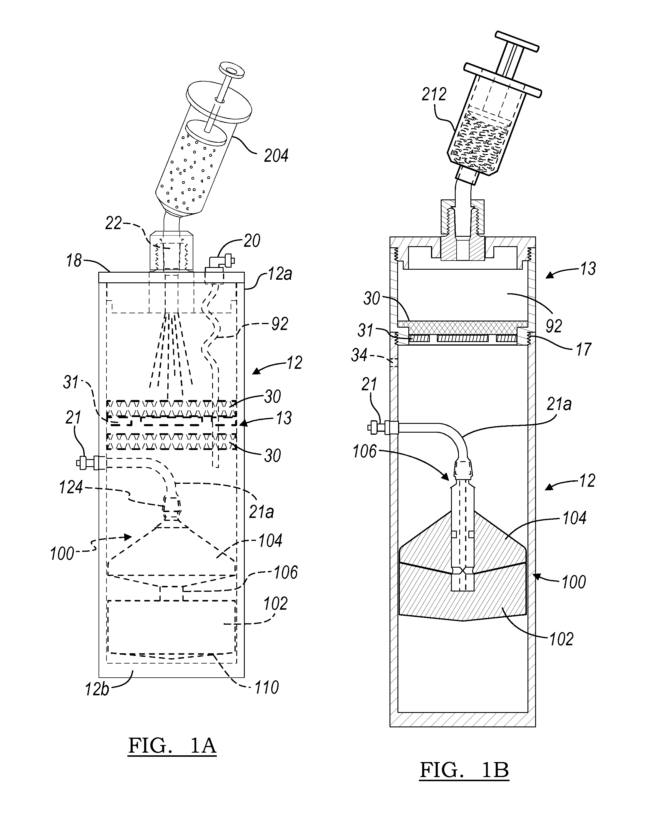
1. A method of separating a component of a multiple component material, comprising: separating, within a container system, at least a portion of a solid portion from a liquid portion of a multicomponent material at least by retaining the portion of the solid portion of the multiple component material in a first section of the container system with a filtration system having a first filter media portion positioned between the first section and a second section of the container system, wherein a buoy is slidably received within the second section, the buoy having a first buoy member and a second buoy member; forming at least a first fraction and a second fraction of the liquid portion after the liquid portion has moved from the first section to the second section, wherein the buoy moves within the second section to isolate the first fraction at least from the second fraction; removing the first section from the second section following fractionation such that the first filter media portion is removed from the second section, wherein the first filter media portion retains the portion of the solid portion of the multiple component material in the first section during fractionation; and extracting the first fraction from the second section.
2. The method of claim 1, further comprising: sizing the first section and the second section to have the same transverse cross-section dimensions.
3. The method of claim 1, further comprising: providing the first section to include the first filter media portion and a second filter media portion.
4. The method of claim 1, further comprising: obtaining a volume of the multiple component material from an anatomy, the volume comprising the solid and liquid portions; and placing the obtained volume of the multiple component material in the container system having at least the first section and the second section.
5. The method of claim 4, wherein providing the volume of the multiple component material comprises a selected volume of bone reaming material.
6. The method of claim 1, wherein forming at least the first fraction and the second fraction of the liquid portion includes applying a force to the container system to form at least the first fraction and the second fraction.
7. The method of claim 6, wherein applying the force includes centrifuging the container system to move the buoy to a selected position relative to the volume of a fraction of a whole heterogeneous material.
8. The method of claim 1, further comprising: at least one of applying the first fraction to an implantable medical device, applying the first fraction to a wound, applying the first fraction to a reamed bone, applying the first fraction to a resected bone, or combinations thereof.
9. The method of claim 1, further comprising a connecting member connecting the first buoy member and the second buoy member, at least the second buoy member being slidably coupled to the connecting member, such that the second buoy member is movable relative to the first buoy member.
10. The method of claim 1, wherein the first fraction is disposed between the first and second buoy members, and the step of extracting the first fraction from the second section comprises applying suction to a port disposed between the first and second buoys to draw the first fraction into the port and through a cannula in fluid communication with an exterior of the container system.
11. A method of separating a component of a multiple component material, comprising: placing a volume of the multiple component material, including a liquid portion and a solid portion, in a removable filter section of a container, the container having at least the filter section and a fractionation section, wherein a buoy is slidably received within the fractionation section, the buoy having a first buoy member and a second buoy member; separating the solid portion from the liquid portion at least by retaining at least a portion of the solid portion of the multiple component material in the filter section of the container; forming a fraction of the liquid portion in the fractionation section of the container, wherein the buoy moves within the fractionation section to isolate the fraction of the liquid portion; maintaining a connection of the filter section and the fractionation section while forming the fraction of the liquid portion in the fractionation section of the container, wherein the filter section retains the portion of the solid portion of the multiple component material; and extracting the fraction from the fractionation section of the container.
12. The method of claim 11, wherein the filter section and the fractionation section have the same cross-sectional dimensions for connecting the filter and fractionation sections.
13. The method of claim 11, further comprising: removably connecting a first section to the fractionation section.
14. The method of claim 11, wherein forming the fraction includes: applying a force to the multiple component material supported in the filter section.
15. The method of claim 14, wherein the force is applied to at least cause a portion of the liquid portion to move into the fractionation section of the container.
16. The method of claim 14, wherein forming the fraction of the liquid portion includes collecting at least the fraction between the first buoy member and the second buoy member positioned within the fractionation section.
17. The method of claim 11, further comprising a connecting member connecting the first buoy member and the second buoy member, at least the second buoy member being slidably coupled to the connecting member, such that the second buoy member is movable relative to the first buoy member.
18. A method of separating a component of a multiple component material, comprising: providing a container system for separating at least a first portion of a solid portion from a liquid portion of a multiple component material at least by retaining the first portion of the solid portion of the multiple component material in a first section of the container system with a filtration system having a first filter media portion positioned between the first section and a second section of the container system; after the liquid portion has moved from the first section to the second section, providing a fractionation system to form at least one fraction of the liquid portion between a first buoy member and a second buoy member, wherein the first filter media portion retains the first portion of the solid portion of the multiple component material during forming of the at least one fraction of the liquid portion; and providing access within the second section to extract the at least one fraction of the liquid portion from the second section from between the first buoy member and the second buoy member; wherein the first section is removably coupled to the second section.
19. The method of claim 18, wherein the first buoy member and the second buoy member are complementary formed to substantially mate during extracting the at least one fraction of the liquid portion.
20. The method of claim 18, further comprising: providing the solid material to include bone portions and the liquid portion to include whole blood.
21. The method of claim 18, further comprising: providing the first section to be removed from the second section following a separation of at least the solid portion from the liquid portion and prior to a forming of the at least one fraction.
22. The method of claim 18, further comprising a connecting member connecting the first buoy member and the second buoy member, at least the second buoy member being slidably coupled to the connecting member, such that the second buoy member is movable relative to the first buoy member.
23. The method of claim 18, further comprising extracting the at least one fraction of the liquid portion from the second section by applying suction to a port disposed between the first and second buoys to draw the at least one fraction of the liquid portion into the port and through a cannula in fluid communication with an exterior of the container system.
Description
FIELD
The present teachings relate to a multiple component material and an apparatus to separate and concentrate the various components. More particularly, the present teachings relate to a container operable with a centrifuge to separate and concentrate various biological components.
BACKGROUND
Multi-phase or multi-component materials where solid and fluids are combined (slurries and suspensions, for example) may be separated into the respective solid, semi-solid, or fluid components and subcomponents thereof. Complex multi-component materials may be difficult to separate because of particle sizes, fluid viscosities, interactions between the materials, etc. Depending on the desired end use of a subcomponent, separation of some multi-component materials may be too labor intensive or time consuming to warrant separating the materials.
For example, in arthroplasty procedures, the materials removed from the subject during bone bed preparation or bone reaming include a mixture of cartilage, bone chips, surrounding blood and fluids, and the dense spongy material known as bone marrow. The bone reaming materials can include beneficial undifferentiated cells, such as mesenchymal stem cells, white blood cells, and platelets which may be used to expedite the healing of the injury site and incision or may be used as therapy in other procedures. To separate the bone reaming materials into the beneficial mesenchymal stem cells is a multi-step process and can occupy hours of preparation and waiting time. An exemplary separation process includes precipitating the unwanted cells via culturing, plating, incubating the preparation, and then washing and centrifuging the preparation several times to concentrate the desired stem cells. This process is time consuming, labor intensive, and inefficient--characteristics that are neither desirable in a self-paced laboratory environment, nor desirable under surgical conditions and time restraints. Accordingly, despite the vast applications of the undifferentiated cells, white blood cells, and platelets in bone reaming material, the extensive labor in separation is too burdensome and therefore, the bone reaming material or bone reaming "debris" is discarded.
Whole blood and fluids from the arthoplasty procedure may also be discarded despite the beneficial components. Like the bone reaming material, these fluids have fractions that may be used to expedite healing and promote tissue health. For example, the whole blood may be separated into platelets, red blood cells, and plasma by density in a device such as a centrifuge. Nonetheless, these methods do not provide a simple or efficient method to extract any more than one fraction and especially a fraction other than the top fraction. Even in these systems, multiple spins may be required to effectively separate the constituents without commingling the sample. These same difficulties may be encountered even using systems incorporating a float or other device that is disposed within the sample at the interfaces of the different fractions during the centrifuge process. Additionally, the current separation systems are generally designed to separate only same phase components and do not work with multiple states of matter such as partial fluid mixtures which contain macroparticles or large sized particles, such as the bone reaming materials described above.
Therefore, it is desired to provide a device to allow for collection of selected constituents from a multi-component material having macroparticles. It is desired to provide a device to allow for the easy and reproducible removal of a particular fraction which does not happen to be the top fraction of a sample. It is desired to remove the required sample without mixing the different fractions during the extraction process. In addition, it is desired to provide a device which allows for a consistent extraction of known volumes or concentrations of the fraction elements. Moreover, it is desired to separate and concentrate a multi-state composition with one centrifugation step.
SUMMARY
An apparatus that separates and concentrates a selected fraction or component of a fluid, such as a biological fluid. For example, undifferentiated cells, such as mesenchymal stem cells, platelet fraction, buffy coat, or white blood cell fraction can be separated from bone reaming material, whole blood, bone marrow aspirate, and other materials. The apparatus, when used with a centrifuge, is generally able to create at least two fractions. It also provides for a new method of extracting the desired fraction or component or middle fraction from a sample.
The apparatus includes a container to be placed in a centrifuge after being filled with a sample. The apparatus can include a filtration system, a separation system, and an extraction system. The filtration system prevents the migration of undesired solids into the buoy system. The separation system includes a buoy or fraction separator, having a selected density that may be less than one fraction but greater than a second fraction, and is disposed in the container. In addition, a second buoy may be placed in the container with the first. The extraction system is connected to the buoy system or to the collection chamber such that the fraction in the container can be collected and drawn outside of the chamber. During the centrifuge processing, the buoy is forced away from a bottom of the container as the denser fraction collects at the bottom of the container. The buoy is generally able to physically separate the denser fraction from another fraction of the sample. The fractions can be withdrawn using the extraction system or member.
In addition to providing a first buoy and/or a second buoy, a buoy system may be provided. Generally, the buoy system may separate the sample into at least three fractions. The fractions may be separated or extracted from the container without substantially comingling the various fractions. Generally, a first buoy and a second buoy operate together to separate the sample into the various fractions and a syringe or tube may then be interconnected with a portion of the buoy system to extract the selected fractions. For example, a first buoy may be generally density tuned to a white blood cell fraction of a whole blood sample, and a second buoy tuned to a density less than the density of the undifferentiated cell fraction from bone reaming material.
According to various embodiments a method of forming at least one fraction for application relative to an anatomy is taught. The method may include obtaining a volume of a heterogeneous whole material and separating the material into the desired fraction(s). At least one of the fractions may be applied to the scaffold.
Further areas of applicability of the present teachings will become apparent from the detailed description provided hereinafter. It should be understood that the detailed description and specific examples, while indicating various embodiments of the teachings, are intended for purposes of illustration only and are not intended to limit the scope of the teachings.
BRIEF DESCRIPTION OF THE DRAWINGS
The present teachings will become more fully understood from the detailed description and the accompanying drawings, wherein:
FIG. 1A is a plan view of a separator according to various embodiments;
FIG. 1B depicts a separator according to various embodiments;
FIG. 1C depicts a separator system being filled with a multi-component material according to various embodiments;
FIG. 1D depicts a separator system after a centrifugation process according to various embodiments;
FIG. 2A depicts a filtration system according to various embodiments;
FIG. 2B depicts a filtration system according to various embodiments;
FIG. 3A is a side plan view of a buoy system according to various embodiments;
FIG. 3B is a cross-sectional view of the buoy system of FIG. 3A;
FIG. 4 is a plan view of a separator including a plunger in a tube according to a second embodiment of the present teachings;
FIG. 5 is a cross-section view taken along line 5-5 of FIG. 4;
FIG. 6 is an exploded view of the separator including a plunger;
FIG. 7A is a perspective view of the separator being filled;
FIG. 7B is a perspective view of a sample in the separator after the centrifuge process;
FIG. 7C is a plan view of the plunger plunged into the tube with the depth gage to further separate the bone reaming sample;
FIG. 7D is a plan view of the platelet fraction and the plasma fractions being extracted from the separator;
FIG. 8 depicts the removal of bone reaming material from a subject; and
FIG. 9 illustrates a plan view of a selected fraction of the separated material being extracted from a tube according to various embodiments.
DETAILED DESCRIPTION OF VARIOUS EMBODIMENTS
The following description of various embodiments is merely exemplary in nature and is in no way intended to limit the teachings, its application, or uses. Although the following description exemplary refers to bone reaming material, whole blood, and/or bone marrow aspirate separation, it will be understood that the present teachings may be used to separate and concentrate any appropriate material. It will be further understood that many multi-component materials containing macroparticles may be separated. The components or fractions are generally inter-mingled in the whole sample but may be separated with a centrifuge device that causes increased local gravity or gravitational forces.
With reference to FIGS. 1A-1D, according to various embodiments a separator 10, also referred to as a concentrator, is illustrated according to a first embodiment of the present teachings. The separator 10 generally includes a tube or container 12 that is adapted to hold a multi-component sample, such as a mixture of a bone reaming material and an anti-coagulated whole blood sample, for further processing. The tube 12 includes a top or open end 12a, which is closeable, and a bottom or closed end 12b. The bottom 12b may also be selectively closeable. Disposed within the tube 12 is a filtration system or member 13 and a separation system or buoy 14, 300. The filtration system 13 and the buoy 14, 300 are in fluid communication within the tube 12. The buoy 14, 300 is generally nearer the bottom end 12b of the tube 12 rather than the open end 12a. The buoy 14, 300 is able to move along a central axis A of the tube 12. A cap 18 substantially mates with the open end 12a of the tube 12 to close the tube 12 save for ports formed in the cap 18. Extending from the cap 18 is a plasma valve or port 20 that communicates with an area, described further herein, within the tube 12 defined between the buoy 14, 300 and the cap 18. It will be understood that the plasma port 20 is merely exemplary in nature and simply allows for removal of a selected fraction of a sample, such as plasma from the mixture of bone reaming material and whole blood.
Although the tube 12 is described here as a cylinder, it will be understood that other shapes may be used, such as polygons. The internal portions, such as the cap 18, filtration system 13, and buoy 14, 300, would also include this alternate shape. Preferably the tube 12 is formed of a thermal plastic material which is flexible under the forces required to separate multi-component biological materials such as a mixture of bone reaming material and whole blood. The tube 12 may be made of a material that includes the properties of both lipid and alcohol resistance. These properties help increase the separation speed and decrease the amount of material which may cling to the tube wall 23. For example, Cyrolite MED2.RTM. produced by Cyro Industries of Rockaway, N.J. may be used to produce the tube 12.
The tube 12 has a tube wall 23 with a thickness of between about 0.01 millimeters and about 30.0 millimeters, although the tube wall 23 may be any appropriate thickness. The thickness of the tube wall 23 allows the tube wall 23 to flex during the centrifuge process yet be rigid enough for further processing of a bone reaming debris and blood sample disposed in the tube 12. The tube 12 is closed at the bottom end 12b with a tube bottom 24 formed of the same material as the tube wall 23 and is formed integrally therewith. Generally the tube bottom 24 has a thickness which is substantially rigid under the forces required to separate the sample such that it does not flex.
The cap 18 provides a structure to substantially close the tube 12. The cap 18 particularly includes a plate 26 that has an external circumference substantially equal to the external circumference of the tube 12. Extending from the plate 26 and into the tube 12 is a flange 28. The external circumference of the flange 28 is substantially equal to the internal circumference of the tube 12. In this way, the cap 18 substantially closes the tube 12. It will be understood the cap 18 may be in any form so long as the cap 18 substantially closes and/or seals the tube 12 when installed.
The filtration system 13 is generally near the open end 12a of the tube. The filtration system 13 prevents migration of unwanted solid materials, such as macroparticles 32, through the filter and past the buoy 14, 300. The macroparticles 32 can be used for other purposes, such as void filling, but can be selected to not be further separated within the tube 12.
The filtration system 13 can comprise a mesh 30. The mesh 30 can be made of a rigid material such as high molecular weight PTFE. The mesh 30 can be rigid enough to support a mass during a centrifuge procedure. Alternatively, or in addition thereto, a support can be provided to support the mesh and the macroparicles during a selected procedure. For example, a filter plate 31 can be provided to support the mesh 30. The filter plate 31 can includes spacers large enough to allow a material to pass there through, but also support the mesh 30.
The mesh 30 can have a pore or mesh size that is of a sufficient diameter to prevent passage of unselected solid materials or macroparticles 32 through the filtration system 13. An example mesh size useful in the separation and concentration of a mixture of bone reaming material and whole blood is from about 10 micrometers to about 200 micrometers. In various embodiments, the mesh size is less than about 50 micrometers. It is understood that the mesh size may be modified depending on the fine or coarse nature of the bone reaming and the resultant sized macroparticles 32. As used herein, "macroparticle" refers to a solid or semi-solid material having a greater diameter than the pores used in the filtration system 13. For example, where the mesh 30 has a pore size of about 50 micrometers, the macroparticle 32 has a greatest cross-section length of greater than about 50 micrometers. In yet another example, where the mesh size is about 1 centimeter, the macroparticle 32 would have a cross-section length of greater than about 1 centimeter.
The filtration system 13 may be provided to be separable from the tube 12. For example, a seam or break 34 can be formed on the tube 12 such that the filtration system 13 and macroparticles 32 collected therein can be easily removed from the tube 12. The break 34 may include perforations or scoring that allows for removal either by hand manipulation from a user (such as snapping off the filtration system) or require the use of a tool to cut or remove the filtration member. As depicted in FIGS. 2A and 2B, filtration system 13 can also include threads 17 as a mechanism to separate the filtration system from the tube 12. The threads 17, or similar separation mechanism, can allow for re-attaching the cap 18 to the top end 12a of the tube 12 after unscrewing and removing the filtration system 13.
As illustrated in FIG. 1A, multiple mesh filters 30 can be included in the filtration system 13. Each mesh 30 filter may have a different pore size to enhance the trapping of macroparticles in the filtration system 13. For example, it may be desirable to have a mesh 30 located closest to the cap 18 having a greater mesh size than another mesh 30 located nearer the buoy 14, 300. As disclosed later herein, the filtration system 13 may be used to collect bone particles useful for filling bone voids. In various embodiments the material provided to the tube 12 can include reaming debris from bone, a blood sample, or other portions that may define a whole sample. The whole sample can be placed in the tube 12 to separated according to various embodiments.
The separation system 10 can also includes the buoy 14, 300 to assist in separation and extraction of selected fractions from the whole sample. The buoys 14, 300 can include an upper or collection face 46 that defines an inverse cone or concave surface. Generally the cone has an angle of between about 0.5.degree. to about 45.degree., and may be about 0.5.degree. to about 90.degree. from a vertical axis, wherein the apex of the cone is within the buoy 14, 300. The collection face 46 forms a depression in the buoy 14, 300 which collects and concentrates material during the separation process. Additionally, the buoy 14, 300 has a bottom face 40 that defines an inverse cone, dome, or covered surface. The buoy bottom face 40 includes an apex 42 that engages the tube bottom 24 before a buoy edge 44 engages the tube bottom 24. The buoy 14, 300 includes a material that is a substantially rigid such that the buoy edges 44 never meet the tube bottom 24. Therefore, there is a gap or free space 46 formed between the buoy edge 44 and the tube bottom 24 along the perimeter of the buoy 14, 300.
The separator 10 is generally provided to separate a multi-component material that can have macroparticles 32 that includes various components or constituents of varying densities that are commingled or mixed together. The separator 10 includes the buoy 14, 300 that is of a selected density depending upon a selected constituent of the multi-constituent material. Although the buoy 14, 300 may be tuned or of any selected density, the following example relates to separation of a bone reaming debris and whole blood mixture into various components. Therefore, the buoy 14, 300 will be discussed to include a selected density relative to bone reaming material and whole blood separation. It will be understood, however, that the buoy 14, 300 may be of any appropriate density depending upon the multi-component fluid being separated.
The buoy 14, 300 may be formed of any appropriate material that may have a selected density. With bone reaming materials, selected materials can include white blood cells, platelets, or undifferentiated cells, including, but not limited to mesenchymal stem cells. For example, when the separator 10 is to separate blood, the buoy 14, 300 generally has a density which is greater than that of platelets, red blood cells, and white blood cells in a bone reaming material and whole blood sample, but less than the undifferentiated cell fraction of the sample. For bone reaming material and whole blood mixtures, the density of the buoy 14, 300 is generally between about 1.02 g/cc and about 1.09 g/cc. This range is sufficient to separate at least red blood cells from the other fractions. The bone reaming debris and whole blood mixture (or saline) provides a choice of several desirable fractions, such as the white blood cells, platelets, and undifferentiated cells discussed herein. The value of 1.02 g/cc to about 1.09 g/cc is given only as a benchmark, assuming that the desired collection fraction is the platelet fraction or the undifferentiated stem cells as the value segregates the white and red blood cells from the other fractions. If for example, a different fraction was desired for collection, the density fraction, or a slightly higher density, would be an appropriate for the buoy to separate the undesired fraction.
To achieve the selected density, the buoy 14, 300 may be formed as a composite or multi-piece construction, including a plurality of materials. Particularly, a first or outside portion 48 defines the collection face or surface 38 and the buoy edge 44 and is formed of the same material as the tube 12. The outside portion 48 defines a cup or void into which a plug or insert 50 is placed. The insert 50 has a mass such that the density of the entire buoy 14, 300 is within the selected range, for example the range described above. Generally, a high density polyethylene may be used, but the material and size of the insert 50 may be altered to produce the desired density of the buoy 14, 300. Alternatively, the buoy 14, 300 may be formed of a single suitable material that has a density in the selected range. Nevertheless, the buoy 14, 300 formed unitarily or of a single material would still include the other portions described in conjunction with the buoy 14, 300.
The outside portion 48 of the buoy 14, 300 also defines the outside circumference of the buoy 14, 300. The outside circumference of the buoy 14, 300 is very close to the internal circumference of the tube 12. Due to the operation of the buoy 14, 300, however, described further herein, there is a slight gap between the outside of the buoy 14, 300 and the inside of the tube 12. Generally, this gap is between about 1 and about 10 thousandths of an inch around the entire circumference of the buoy 14, 300. Generally, it is desired that the distance between the outside circumference of the buoy 14, 300 and the inside circumference of the tube 12 is great enough to allow a selected material or component to pass. For example, in bone reaming material the distance is selected so that white and red blood cells may pass through the gap without being lysed, damaged, or activated.
Referring to FIGS. 3A and 3B, a buoy system 100 is illustrated. The buoy system 100 generally includes a first buoy or fraction separator member 102 and a second buoy member or fraction separator 104. The first buoy 102 and the second buoy 104 may be operably interconnected with a buoy system cylinder or member 106. The buoy system 100 may be placed in a tube, such as the tube 12. The tube 12 may be formed of any appropriate material, such as the Cryolite Med.RTM. 2 as discussed above. Nevertheless, the buoy system 100 may be designed to fit in the tube 12 or may be formed to fit in any appropriate member that may be disposed within a selected centrifuging device. It will be understood that the following discussion relating to buoy system 100 to be substantially matched to the size of the tube 12 is merely exemplary. As the buoy 14, 300 may be sized to fit in any appropriate tube, the buoy system 100 may also be sized to fit in any appropriate tube. It will be further understood that the tube 12 may be any appropriate shape. The tube 12 need not only be cylindrical but may also be or include conical portions, polygonal portions, or any other appropriate shapes.
The first buoy 102 of the buoy system 100 may be generally similar in geometry to the buoy 14, 300. It will be understood that the first buoy member 102 may be formed in the appropriate manner including shape or size to achieve selected results. Nevertheless, the first buoy member 102 generally includes an exterior diameter that may be slightly smaller than the interior diameter of the tube 12. Therefore, the first buoy member 102 may be able to move within the tube 12 during the centrifugal process. Also, as discussed above, the tube 12 may flex slightly during the centrifuging process, thus allowing the first buoy member 102 to include an exterior diameter substantially equivalent to the interior diameter of the tube 12. As discussed further herein, during the centrifugation process, a portion of the fraction of a sample may pass between the exterior wall of the first buoy member 102 and the tube 12.
The first buoy member 102 may generally include a density that is substantially equivalent to a first or selected fraction of the sample. If the sample to be separated includes bone reaming material and is desired to separate the white/red blood cells from the other portions of the sample, the first buoy member 102 may have a selected density that may be about 1.00 grams per cc (g/cc) to about 1.10 g/cc. It will be understood that the density of the first buoy member 102 may be any appropriate density, depending upon the fraction to be separated, and this range of densities is merely exemplary for separating white/red blood cells from a whole blood sample.
In addition, the first buoy member 102 includes a collection face or area 108 at a proximal or upper portion of the first buoy member 102. The collection face 108 generally defines a concave area of the first buoy member 102 and may have a selected angle of concavity. The buoy assembly 100 defines a central axis D. The collection face 108 defines a surface E that is formed at an angle .gamma. to the central axis D of the buoy system 100. The angle .gamma. may be any appropriate angle and may be about 0.5.degree. to about 90.degree.. The angle .gamma. may, however, be between about 45.degree. and 89.5.degree.. Nevertheless, it will be understood that the angle .gamma. may be any appropriate angle to assist in collection of a selected fraction or portion of the sample by the first buoy member 102.
A bottom or lower surface 110 of the first buoy member 102 may define a bottom face. The bottom face 110 may also be formed at an angle D relative to the central axis D. The bottom surface 110 defines a surface or plane F that may be formed at an angle .DELTA. relative to the central axis D of the buoy system 100. The angle .DELTA. may be any appropriate angle and may be about 90.degree. to about 180.degree.. For example, the angle .DELTA. may be about 105.degree.. Similarly to the buoy bottom face 40, the bottom surface 110 defines an apex 112 that may first engage the bottom 12b of the tube 12, such that most or the majority of the bottom surface 110 does not engage the tube 12. As illustrated further herein, the apex 112 allows for a free space or gap to be formed between the bottom face 110 of the first buoy member 102 and the bottom 12b of the tube 12.
The second buoy member 104 may include an outer diameter substantially equivalent to the outer diameter of the first buoy member 102. Therefore, the second buoy 104 may move with the first buoy 102, particularly if the second buoy 104 is interconnected with the first buoy 102 with the buoy central cylinder 106. Nevertheless, the second buoy member 104 may be allowed to move substantially freely within the tube 12 during the centrifuging process.
The second buoy member 104 also includes an upper or superior surface 114 that defines a plane G that is formed at an angle relative to the central axis D of the buoy system 100. The angle .epsilon. of the plane G relative to the central axis D of the buoy system 100 may be any appropriate angle. For example, the angle .epsilon. may be about 90.degree. to about 180.degree.. Generally, the angle .epsilon. may assist in allowing a selected fraction or a portion of the sample to pass over the top surface 114 and past the second buoy member 104 during the centrifuging process.
The second buoy member 104 also define a bottom or inferior surface 116 that also defines a plane H that may be formed at an angle K relative to the central axis D of the buoy system 100. The angle K may be any appropriate angle, such as about 90.degree. to about 150.degree.. Nevertheless, the angle K may be convex and substantially complimentary to the angle .gamma. of the collection face 108 that may be concave of the first buoy member 102. For example, if the angle .gamma. is about 80.degree., the angle K may be about 80.degree. as well so that the surfaces 316 and 308 mate as the first buoy member 102 engages the second buoy member 104. This may be for any appropriate reason, such as extraction of a fraction that may be disposed near the collection face 108 of the first buoy member 102. Nevertheless, the angle K may be any appropriate angle as the angle .gamma..
The second buoy member 104 may be formed to include any appropriate density. For example, the second buoy member 104 may include a density that is less than the plasma fraction of a bone reaming material and whole blood sample. It will be understood that the second buoy member 104 may include any appropriate density and a density that is less than the undifferentiated cell and/or platelet fractions of a bone reaming material blood sample is merely exemplary. Nevertheless, if a bone reaming material sample is desired to be separated and the plasma sample is to be substantially separated from another fraction, the second buoy member 104 may include a density that is less than the plasma fraction. Therefore, the density of the second buoy member 104 may be about 0.01 g/cc to about 1.03 g/cc.
The buoy post 106 may operably interconnect the first buoy member 102 and the second buoy member 104. The buoy post 106 may be any appropriate connection member. The buoy post need not be a single cylindrical portion. For example the buoy post 106 may include one or more members interconnecting the first buoy member 102 and the second buoy member 104, such as around a perimeter thereof. In addition, the buoy post 106 may include any appropriate shape or geometry.
The buoy system post 106 may be rigidly affixed to the first buoy member 102 and the second buoy member 104, such that the first buoy member 102 may not move relative to the second buoy member 104 and vice versa. Alternatively, the buoy post 106 may be slidably connected to either or both the first buoy member 102 and the second buoy member 104. According to various embodiments, the buoy post 106 is generally fixedly connected to the first buoy member 102 and slidably interconnected to the second buoy member 104. The buoy post 106 may include a catch portion or lip 120 that is able to engage a portion of the second buoy member 104, such that a range of travel of the second buoy member 104, relative to the first buoy member 102 is limited. Nevertheless, the range of travel of the second buoy member 104 towards the first buoy member 102 may be substantially unlimited until the second buoy member 104 engages the first buoy member 102.
The buoy post 106 may also define a central cannula or bore 122. The post bore 122 may include a connection portion 124 substantially defined near an upper or a proximal end of the buoy post 106. This may allow for interconnection of various components with the buoy post 106, such that various components may be moved through the bore 122 from an exterior location. The buoy post 106 may also define a port or cannula 126 that connects the post cannula 122 with the collection face 108. Therefore, a substance may travel through the post cannula 122 and through the port 126. Various substances may then be provided to or removed from the collection face 108 of the first buoy member 102.
The tube 12 may include the cap 18 that further defines a plasma valve or port 20. Extending through the cap 18 and interconnecting with a first flexible tube or member 54, the plasma port 20 may be used to extract plasma of the sample that is positioned above the second buoy member 104. The tube 12 may also define a second port 21, which may also be referred to as a plasma rich port (PRP). As discussed herein, a second flexible member, such as a flexible tube 21a, may interconnect the PRP port 21 and a connection portion 124 of a buoy cylinder 106.
Other portions of the separator system 10, particularly those portions of the tube 12 and the cap 18 that have various valves connected therewith may be included in the tube 12 and used with the buoy system 100. Nevertheless, once the buoy system 100 is interconnected, it may be positioned in the interior of the tube 12 and the syringe 200 used to place a sample into the tube 12.
The multi-component sample may be positioned in the separator 10 adjacent to the filtration system 13 for separation and concentration. The bone reaming material, whole blood, bone marrow aspirate, or other materials may be positioned by inserting the materials using a syringe through the port 22 or by removing the cap 18 and spreading the multi-component material into the region above the filtration system 13. In the latter placement method, the cap 18 is screwed or otherwise secured into place on the separator 10. Additional materials can be added to the multi-component sample to maintain the integrity of the sample, such as an anticoagulant. It will also be understood that various centrifuge times or forces may be altered depending upon the exact material that is being separated with the separator 10. It will also be understood that the separation of bone reaming material, a mixture of whole blood and bone reaming material, or whole blood, are merely exemplary of the materials that may be separated using the separator 10. It will be understood that two buoys 102 and 104 may generally be near one another when the sample is positioned in the tube 12, but are illustrated apart for clarity of the present discussion.
After the sample is positioned within the tube 12, as described above, a cap may be positioned over the port 22, such that the sample is not allowed to escape from the tube 12. After the sample is placed in the tube 12 and the cap 52 placed on the port 22, the tube 12 including the sample and the buoy system 100 may be centrifuged. The system 10 may remain stationary for a selected amount of time prior to centrifuging to allow the components of the bone reaming material and whole blood mixture, other than macroparticles 32, such as bone fragments, cartilage, etc. to transverse the filter and collect in the tube 12.
With reference to FIG. 1D, after a centrifugation of the tube 12, including the buoy system 100, substantially three fractions of the sample may be formed. After the bone reaming material sample is delivered to the tube 12, the separator 10 is placed in a centrifuge. The centrifugation forces affect the tube wall 23. The forces compress the tube 12 linearly along axis A thereby bowing or flexing the tube wall 23. As the tube wall 23 compresses it increases the diameter of the tube 12 making it easier for the buoy 14, 300 to move in the direction of the top 12a of the tube 12. In addition, the bottom face 48, defining an inverse cone, helps the initial movement of the buoy 14, 300. Because the buoy 14, 300 is not substantially flat along its bottom, it does not form a vacuum interaction with the tube bottom 24. Therefore, the initial movement of the buoy 14, 300 away from the tube bottom 24 is quicker than if the bottom of the buoy 14, 300 was flat.
During the centrifuge process the white/red bloods cells of the white/red blood cell fraction 222 force the buoy 14, 300 in the direction of the top 12a of the tube 12 because the buoy 14, 300 is less dense than the white/red blood cell fraction 222. Although the bone reaming material, including the white/red blood cells is loaded above the buoy 14, 300, the red blood cells are able to move between the buoy 14, 300 and the tube wall 23 because the circumference of the buoy 14, 300 is less than the internal circumference of the tube 12. During the centrifuge process the buoy 14, 300 stops at an interface of a plasma fraction 224 and the white/red blood cell fraction 222 because of the selected or tuned density of the buoy 14, 300.
With particular reference to FIG. 1D, the centrifuge process has been completed and the buoy 14, 300 has moved to the interface of the white/red blood cell fraction 222 and plasma fraction 224. After the centrifuge has slowed or stopped, and before or after the tube 12 has been removed from the centrifuge, the tube wall 23 decompresses which helps support the buoy 14, 300 at the interface position. It is also understood that applying an external pressure to the tube 12 via fingers or another apparatus may help stabilize the buoy 14, 300 during the plunging procedure described herein.
A first fraction 130 may be positioned between the bottom face 110 and the bottom of the tube 24. A second fraction may be positioned between the collection face 108 and the bottom surface 116 of the second buoy 104. In addition, a third fraction may be positioned between the upper surface 114 and the cap 18 of the tube 12. Generally, the first fraction 130, the second fraction 132, and the third fraction 134 are substantially physically separated with the buoy system 100. During the centrifugation process, the tube 12 may flex slightly to allow for ease of movement of the buoy system 100 through the tube 12 and the sample. Nevertheless, the buoy system 100, during the centrifugation process, substantially creates the three fractions 130, 132, and 134 without the operation of an operator. Therefore, the formation of at least three fractions may be substantially simultaneous and automatic using the buoy system 100.
The buoy system 100 substantially separates the fractions 130, 132, and 134, such that they may be easily removed from the tube 12. For example, with reference to FIG. 1D, a syringe or other instrument 140 may be used to extract the second fraction 132 by interconnecting a cannula or bored tube 142 with the connection portion 124 of the buoy cylinder 106. By drawing the plunger 144 into the extraction syringe 140, a vacuum or upward force is produced within the extraction syringe 140. This force draws the second fraction 132 through the ports 126 of the buoy post 106 and through the buoy cannula 122. Therefore, the second fraction 132 may be extracted from the tube 12 without substantially comingling the second fraction 132 with either the first fraction 130 or the third fraction 134. The second fraction 132 is drawn in the direction of arrow M through the cannula 122 and into the extraction syringe 140.
It will be understood that the second tube 21a may also be used. The extraction syringe 140 may be interconnected with the PRP 21 that is interconnected with the connection portion 124 of the buoy cylinder 106. As discussed herein the buoy cylinder allows access to the platelet rich area between the buoy portions. Thus, it will be understood, that access may be obtained and the platelet rich portion of the sample, between the two buoys, may be extracted in a plurality of ways. The illustrations and method described herein is merely exemplary.
Alternatively, if the post 106 is not provided other portions may be provided to gain access to the second fraction 132. For example, if a plurality of members are provided around the perimeter of the first buoy 102 and the second buoy 104 a valve portion, such as a puncture-able valve, may be provided in the second buoy 104 to be punctured with an object. In this way an extraction needle may puncture the valve to gain access to the second fraction 132. Regardless, it will be understood that the buoy system 100 may be able to form a plurality of fractions, such as the three fractions 130, 132, and 134 and at least the second fraction 132 may be extracted without substantially commingling the various fractions.
During the extraction of the second fraction 132 through the cannula 122, the second buoy member 104 may move in the direction of arrow M towards the first buoy member 102. As described above, the collection face 108 of the first buoy member may include an angle .gamma. that is substantially complementary to the bottom face 116 of the second buoy member 104. Therefore, if the second buoy member 104 is allowed to move along the buoy cylinder 106, the bottom face 116 of the second buoy member 104 may be able to substantially mate with the collection face 108 of the first buoy member 102. Alternatively, if the second buoy member 104 is not allowed to move, the second buoy member may be provided with a vent port or valve, such that the extraction of the second fraction 132 from the collection face 108 may not be hindered by the buildup of undesirable forces. Nevertheless, if the second buoy member 104 may move, the interaction of the bottom face 116 of the second buoy member 104 may assist in substantially removing the entire second fraction 132 from the tube 12. As described above, the bottom face 84 of the plunger 16 may also serve a similar purpose when engaging the collection face 46 of the buoy 14, 300.
Once the second fraction 132 has been extracted from the tube 12, the second buoy member 104 may substantially mate with a portion of the first buoy member 102. As discussed above, the second buoy member 104 may substantially only mate with the first buoy member 102 if the second buoy member 104 is able to substantially move relative to the first buoy member 102. Therefore, it will be understood that the second buoy member 104 need not necessarily mate with the first buoy member 102 and is merely exemplary of an operation of various embodiments. Nevertheless, once the second fraction 132 has been extracted from the tube 12, the port 21 may be used in conjunction with a selected instrument, such as a plasma extraction syringe 200 to remove the plasma or the third fraction 134 from the tube 12 using the extraction tube 54 interconnected with the port 20.
As described above, the tube 54 allows for extraction of the third fraction 134 from the tube 12 without commingling the third fraction 134 with the remaining first fraction 130 in the tube 12. Therefore, similar to the separator and extraction system 10, three fractions may be substantially formed within the tube 12 with the buoy system 100 and may be extracted without substantially commingling the various fractions. Once the third fraction 134 is extracted from the tube 12, the buoy system 100 may be removed from the tube 12, such that the first fraction 130 may be removed from the tube 12. Alternatively, the first fraction 130 may be discarded with the tube 12 and the buoy system 100 as a disposable system. Alternatively, the system may be substantially reusable, such that it can be sterilized and may be sterilized for various uses.
The description of the method of use of the buoy system 100 is exemplary of a method of using a system according to various other embodiments. It will be understood, however, that various specifics may be used from various embodiments to allow for the extraction of selected fractions. For example, the centrifugation process may be substantially a single step centrifugation process. The buoy system 100, according to various embodiments, may allow for the formation of three fractions during a single centrifugation process.
The separator 10 is then spun in the centrifuge in a range between about 1,000 and about 8,000 RPMs. This produces a force between about 65 and about 4500 times greater than the force of normal gravity, as generally calculated in the art, on the separator 10 and the bone reaming material sample placed in the separator 10. At this force, the more dense material in a bone reaming material sample is forced towards the bottom 12b of the tube 12. The dense material, such as white and red blood cells or a white/white/red blood cell fraction 222, collects on the tube bottom 24. Because the buoy 14, 300 has a density that is less than the white/red blood cell fraction 222, it is forced in a direction toward the top 12a of the tube 12 in the centrifuge. Nevertheless, because the buoy 14, 300 is denser than a plasma fraction 224, the buoy 14, 300 does not reach the top 12a of the tube 12.
Referring to FIGS. 4-6, in a second embodiment of the present teachings a plunger is incorporated into the separator 10. The plunger 60 is also able to move within the tube 12 generally between a position closer to the open end 12a to a position closer to the closed end 12b of the tube 12.
In embodiments utilizing the piston, the cap 18 also includes a depth gage port 62. Extending from the plunger 60 and through the depth gage port 62 is a first plunger port 22. A depth guide or gage 38 includes a female connector 25 adapted to connect with the first plunger port 22. The depth gage 38 also includes a depth gage housing or cannula 28. The depth gage housing 66 defines a depth gage bore 68. Incorporated in the housing 66 and extending distal from the end mating with the plunger is a neck 70. The neck 70 includes external neck threads 72. The external neck threads 72 are adapted to engage appropriate internal threads of a mating member.
The mating member may include a compression nut 74 that mates with the external neck threads 72 to lock a depth gage rod 76 in a predetermined position. A split bushing 39 is also provided to substantially seal the depth gage housing 66 when the depth gage rod 76 is locked in place. The depth gage rod 76 extends through the depth gage housing 66 and terminates at a rod handle 78. The rod handle 78 may be a form easily manipulated by a human operator. The rod 76 extends coaxially with axis A of the tube 12. The depth gage rod 76 extends through the plunger 60 a predetermined distance and may be locked at that distance with the compression nut 74.
The plunger 60 includes a plunger front or collection face 84 and a plunger wall 80 that extends from the plunger front face 84. The plunger wall 80 extends relatively perpendicular to the plunger front face 84 and substantially parallel to the tube wall 23. Extending from the center of the plunger 60 is a sample collection projection 82. Extending from the top of the collection projection 82 is the first plunger port 22. The sample collection projection 82 includes a plunger sample collection bore 68 defined therethrough. The plunger sample collection bore 68 terminates at a sample collection aperture 86 that is substantially in the center of the plunger front face 84. The plunger front face 84 also defines an inverse cone where the sample collection aperture 86 is the apex of the cone. The plunger front face 84 defines a cone with an angle substantially similar or complimentary to the collection face 46 of the buoy 14, 300. In this way, the plunger front face 84 may mate substantially completely with the collection face 46 for reasons described more fully herein.
The plunger 60 also includes a back face 88. Extending from the plunger front face 84 to the back face 88 is a bore 74. A check valve 90 is operably connected to the bore 74. The check valve 90 allows a liquid to move from the plunger front face 84 to the back face 88 while not allowing the liquid to move from the back face 88 to the plunger front face 84. Therefore, the check valve 90 is substantially a one-way valve which allows a material to move in only one direction. The check valve 90 may also operate automatically allowing flow in only one predetermined direction. Alternatively, the check valve 90 may be operated manually and include a portion extending from the check valve 90 requiring manipulation to stop or start a flow through the check valve 90.
The plunger 60 may be made out of any appropriate material which does not interfere with the separation of the fractions of the fluid, such as whole blood. The plunger 60, however, is made of a material that is flexible or at least partially deformable. A flexible material allows the plunger 60 to have an external circumference defined by the plunger walls 63 that is substantially equal to the internal circumference of the tube 12. Because of the deformability of the plunger 60, however, the plunger 60 is still able to move within the tube 12. The plunger 60 is able to move through the tube 12 and also substantially wipe the interior of the tube wall 23. This creates, generally, a moveable seal within the tube 12. Thus, substantially no material escapes the action of the separator 10 when the plunger 60 is plunged into the tube 12. This also helps concentrate the portion of the sample desired to be collected, described more fully herein.
Formed through the center of the plate 26 is the depth gage port 62. The depth gage port 62 is also adapted to receive the sample collection projection 82. The first plunger port 22 extends above the plate 26 through the depth gage port 62. The circumference of the depth gage port 62 is substantially equal to the external circumference of the sample collection projection 82 such that a liquid seal is formed. The plate 26 defines a sample face 84 that includes an interior side of the cap 18. The area between the sample face 84 of the cap 18 and the back face 88 of the plunger 60 define a plasma collection area 92. Although the plasma collection area 92 is exemplary called the plasma collection area, it will be understood that the plasma collection area 92 may also collect any appropriate fraction of the sample that is positioned within a separator 10. The plasma collection area 92 is merely an exemplary name and an example of what material may be collected in the area of the separator 10. As discussed herein, the separator 10 may used to separate whole blood into various fractions, therefore the plasma collection area 92 is used to collect plasma. The plasma collection area 92 also allows a space for the check valve 90 to be installed.
A second bore 94 is formed in the plate 26. Extending through the second bore 94 is the fraction collection valve 20. In liquid communication with the fraction collection valve 20 is a plasma collection tube 54. The plasma collection tube 54 has a length such that the plasma collection tube 54 is able to extend from the fraction collection valve 20 to substantially the tube bottom 24. The plasma collection tube 54, however, is flexible enough such that it may be folded or compressed to fit within the plasma collection area 92 when the plunger is substantially near the top 12a of the tube 12. The plasma collection tube 54 may also be connected to a hose barb 93 that includes a plasma collection bore 93a. The plasma collection bore 93a is substantially level with the plunger back face 88. Alternatively, the plasma collection bore 93a may be positioned below the plunger back face 88 but in fluid communication with the plasma collection tube 54.
The outboard side of the fraction collection valve 20 may include external threads 94 to mate with internal threads of a plasma valve cap 96. Therefore, the fraction collection valve 20 may be selectively opened and closed via the plasma valve cap 96. It will be understood, however, that other appropriate means may be used to open and close the fraction collection valve 20 such as a clip or a plug. It will be understood that the fraction collection valve 20, plasma collection tube 54, plasma bore 23a may be used to collect any appropriate material or fraction from the separator 10.
Also formed in the plate 26 is a vent bore 98. The vent bore 98 allows air to flow into the collection area 92 as the plunger 60 is being plunged into the tube 12. The vent bore 98 may include an air filter 101 such that liquid cannot escape from the tube 12. The air filter 101 allows air to enter or escape from the collection area 92 while maintaining the liquid seal of the tube 12 produced by the cap 18.
Selectively attachable to the first plunger port 22 is the depth gage 38. The female connector 24 interconnects the depth gage housing 66 to the first plunger port 22. Internal threads in the female connector 24 mate with an external thread 103 formed on the first plunger port 22. It will be understood, however, that other engagement mechanisms between the depth gage 38 and the plunger 60 may be used. For example, a snap connection rather than a threaded connection between the two may be used.
The depth gage housing 66 is formed to be substantially rigid. Suitable materials, when sized properly, include polycarbonate and CYRO MED2.RTM.. The material preferably is both rigid and does not substantially react with the sample. It is rigid enough to provide a mechanism to plunge the plunger 60 into the tube 12. In addition the external circumference of the depth gage housing 66 is substantially equal to the circumference of the depth gage port 62 in the plate 26. Therefore, as the plunger 60 is being plunged into the tube 12 with the depth gage 38, no liquid material is allowed to escape around the depth gage housing 66 and through depth gage port 62.
Formed within the depth gage housing 66 is the bore 68 which receives the depth gage rod 76. The depth gage rod 76 extends through the sample collection bore 68 of the sample collection projection 82 and protrudes through the sample collection aperture 86 a predetermined length. The depth gage rod 76 extends through the sample collection aperture 86 a length such that when an end 105 of the depth gage rod 76 meets the buoy 14, 300, the volume defined by the collection face 46 and the plunger front face 84 is between about 5 percent and about 30 percent of the total volume of the sample that the tube 12 holds. The projection of the depth gage rod 76 allows for an easily reproducible collection amount and concentration over several trials.
The compression nut 74 locks the depth gage rod 76 in the predetermined position. Nevertheless, once the plunger 60 has been plunged to the desired depth in the tube 12, the compression nut 74 may be loosened so that the depth gage rod 76 may be removed from the plunger 60 and the depth gage housing 66 without moving the plunger 60. A syringe or other appropriate device may then be affixed to the external neck threads 72 of the depth gage 38 to extract the fraction or phase that is between the plunger front face 84 and the collection face 46. As described further herein, the fraction or phase that is left between the plunger front face 84 and the collection face 46 may be the undifferentiated cells or platelets of a bone reaming material sample. Nevertheless, it will be understood that the fraction between the plunger front face 84 and the collection face 46 may be any appropriate fraction of the sample that is disposed in the separator 10.
With reference to FIGS. 7A-7D a method using the separator 10 is illustrated. The following example relates specifically to the taking and separation of a sample of bone reaming material and whole blood from a patient. Nevertheless, it will be understood that another appropriate biological material may be separated and concentrated using the separator 10, such as adipose tissue. The bone reaming material sample may be positioned in the separator 10 and on top of the filtration system 13. As the liquid transverses the mesh 30, the separator 10 can then be used to remove unwanted macroparticles 32, such as bone chips, cartilage, etc. from the bone reaming material.
With reference to FIGS. 7A-7D and to a bone reaming material sample, a sample of bone reaming material taken from a patient is placed in the tube 12. Suitable delivery methods include spreading the material into the open end 12a of the tube using a spatula or scooping the material into the tube 12. An additional suitable delivery method includes connecting a first syringe 204 to the first plunger port 22. After which the bone reaming material sample is provided to the tube 12 via the sample collection bore 68 and sample collection aperture 86. In various embodiments, the bone reaming material is placed directly into the filtration system 13 of the tube 12. In such embodiments, the bone reaming material will filter through the mesh 30 and down towards the bottom of the tube 12b. The filtration system 13 may remain attached to the separator 10 or it may be disengaged using the break 34 prior to centrifugation. It may be advantageous to leave the filtration system 13 engaged with the tube 12 to facilitate extraction of all desired materials from the bone reaming material.
A cap 220 is then placed over the first plunger port 22 to substantially seal the tube 12. Similarly, whole blood or saline may be added to the tube to increase the viscosity of the bone reaming material. The whole blood or saline may also be introduced using the plunger port 22.
On or near collection face 46 is a third fraction 226 including a small, yet concentrated, amount of red blood cells, white blood cells, and a substantial portion of the platelets and undifferentiated cells of the bone reaming material sample. Although the undifferentiated cells are also present near the collection face 46 at this point the solid portions of the buffy coat are more compressed against the collection face 46. The position of the buoy 14, 300 also helps in this matter. Because the buoy 14, 300 is a single body it defines the interface of the plasma fraction 224 and the white/red blood cell fraction 222. Also the density of the buoy 14, 300 assures that it has not passed into the plasma fraction 224. Therefore, the fractions remain separated after the centrifuge process. In addition because the buoy 14, 300 is tuned to the density of the white/red blood cell fraction 222, it is not affected by variations in the density of the plasma fraction 224 and the position of the buoy 14 can always be at the interface of the white/red blood cell fraction 222 and the plasma fraction 224.
With particular reference to FIG. 7C, the depth gage 38 is affixed to the first plunger port 22 of the sample collection projection 82. After connecting the depth gage 38 to the first plunger port 22, the plunger 60 is plunged into the tube 12 by pushing on the depth gage 38. As this is performed the plasma fraction 224, formed and separated above the buoy 14, 300, is able to flow through the check valve 90 into the plasma collection area 92. This displacement of the plasma fraction 224 allows the plunger 60 to be plunged into the tube 12 containing the blood sample.
The plunger 60 is plunged into the tube 12 until the point where the end 105 of the depth gage rod 76 reaches the buoy 14, 300. The volume left in the collection face 46 is the third fraction 226 and is determined by the depth gage 38. It may be adjusted by selectively determining the amount that the depth gage rod 76 extends below the plunger front face 84. By adjusting the depth gage 38, the concentration of the third fraction 226 can be adjusted depending upon the desires of the operator.
The plasma fraction 224 is held in the plasma collection area 92 for later withdrawal. Therefore, the use of the plunger 60 and the buoy 14, 300 creates three distinct fractions that may be removed from the tube 12 after only one spin procedure. The fractions include the white/red blood cell fraction 222, held between the buoy 14, 300 and the tube bottom 24. The third or platelet or undifferentiated cell fraction 226 is held between the plunger 60 and the buoy 14, 300. Finally, the plasma fraction 224 is collected in the plasma collection area 92.
The third fraction 226 may be extracted from the tube 12 first, without commingling the other fractions, through the sample collection bore 68. With particular reference to FIG. 7D, the depth gage rod 76 may be removed from the depth gage housing 66. This creates a sample collection cannula which includes the depth gage bore 68, the sample collection bore 68, and the sample collection aperture 86. After the depth gage rod 76 has been removed, the second syringe 210 may be affixed to the depth gage housing 66 via the external neck threads 72. The second syringe 210 may be substantially similar to the first syringe 204.
Before attempting to withdraw the third fraction 226, the separator 10 may be agitated to re-suspend the platelets and concentrated white/red blood cells in a portion of the plasma remaining in the collection face 46. This allows for easier and more complete removal of the third fraction 226 because it is suspended rather than compressed against the collection face 46. A vacuum is then created in the second syringe 210 by pulling back the plunger to draw the third fraction 226 into the second syringe 210.
As the third fraction 226 is drawn into the second syringe 210 the plunger 60 moves towards the buoy 14, 300. This action is allowed because of the vent bore 98 formed in the cap 18. Atmospheric air is transferred to the plasma collection area 92 through the vent bore 98 to allow the third fraction 226 to be removed. This allows the movement of the plunger 60 towards the buoy 14, 300. This action also allows the plunger 60 to "wipe" the collection face 46. As the plunger front face 84 mates with the collection area 46 the third fraction 226 is pushed into the sample collection aperture 86. This ensures that substantially the entire third fraction 226 collected in the collection area 46 is removed into the second syringe 210. It can also increase the repeatability of the collection volumes. In addition, because the second syringe 210 does not protrude out the sample collection aperture 86, it does not interfere with the collection of the third fraction 226. Once the plunger front face 84 has mated with the collection face 46 there is substantially no volume between the plunger 60 and the buoy 14, 300.
Once the third fraction 226 is extracted the second syringe 210 is removed from the first plunger port 22. Also the extraction of the third fraction 226 leaves the plasma fraction 224 and the red blood cell fractions 222 separated in the tube 12. At this point a third syringe 212 may be affixed to the fraction collection valve 20. The third syringe 212 is connected to the external threads 94 of the fraction collection valve 20 to ensure a liquid tight connection. It will be understood, however, that another connection mechanism such as a snap or compression engagement may be used to connect the third syringe 212 to the fraction collection valve 20.
A vacuum is then created in the third syringe 212 to draw the plasma fraction 224 from the plasma collection area 92 through the plasma collection tube 54. As discussed above, the plasma collection tube 54 is connected to the hose barb 93. Therefore, the plasma flows through the plasma collection bore 93a through the hose barb 93, and then through the plasma collection tube 54. It will be understood that the plasma collection tube 54 may alternatively simply rest on the plunger back face 88 to collect the plasma fraction 224. In this way the plasma fraction 224 may be removed from the separator 10 without commingling it with the white/red blood cell fraction 222. After the plasma fraction 224 is removed, the separator 10 may be dismantled to remove the white/red blood cell fraction 222. Alternatively, the separator 10 may be discarded in an appropriate manner while retaining the white/red blood cell fraction 222.
The separator 10 allows for the collection of three components of a bone reaming material and whole blood sample's fractions with only one centrifugation spin. The interaction of the buoy 14, 300 and the plunger 60 allows a collection of about 40% to nearly 100% of the available buffy coat in the whole blood sample portion of the mixture after a centrifuge processing time of about 5 minutes to about 15 minutes. The complimentary geometry of the plunger front face 84 and the collection face 46 help increase the collection efficiency. Although only the cone geometry is discussed herein, it will be understood that various other geometries may be used with similar results.
The plunger front face 84 being flexible also helps ensure a complete mating with the collection face 46. This, in turn, helps ensure that substantially the entire volume between the two is evacuated. The process first begins with the suction withdrawal of the third fraction 226 via the second syringe 210, but is completed with a fluid force action of the third fraction 226 as the plunger front face 84 mates with the collection face 46. As the plunger front face 84 mates with the collection face 46 the fluid force assists in removal of the selected fraction.
The plunger 60 also substantially wipes the tube wall 23. Because the plunger 60 is formed of a flexible material it forms a seal with the tube wall 23 which is movable. Therefore, substantially no liquid is able to move between the plunger wall 80 and the tube wall 23. Material is substantially only able to go past the plunger front face 84 via the check valve 90.
The complimentary geometry also helps decrease the collection time of the third fraction 226. Therefore, entire time to prepare and remove the third fraction 226 is generally about 5 to about 40 minutes. This efficiency is also assisted by the fact that the separator 10 allows for the removal of the third fraction 226 without first removing the plasma fraction 224, which includes the buffy coat, and respinning the plasma fraction 224. Rather one spin in the separator 10 with the whole blood sample allows for the separation of the buffy coat for easy extraction through the plunger 60.
The separator 10 may be used to separate any appropriate material. The material may be separated for any purpose, such as a surgical procedure. For example, a selected fraction of a whole heterogeneous material or multi-component material may be separated and purified into a desired fraction according to various embodiments. The multi-component material can be harvested from a patient by methods such as bone reaming, as depicted in FIG. 8, or by withdrawing whole blood from the patient. The selected fraction of the bone reaming material may include various components, such as undifferentiated cells. The various undifferentiated cells may be positioned in a selected scaffold or relative to a selected portion of a patient for providing a volume of the undifferentiated cells to the patient. The selected fraction is applied to or delivered to the patient at a selected region of the anatomy. The selected fraction may be placed on a prosthetic, a stent, or any other implantable medical device. The selected fraction may be applied directly to the anatomy or to the medical implant in any appropriate manner, such as by spraying, dipping, infiltrating, or any appropriate method. The macroparticles 32 recovered can also be used to fill a void in bone.
The description of the teachings is merely exemplary in nature and, thus, variations that do not depart from the gist of the teachings are intended to be within the scope of the teachings. Such variations are not to be regarded as a departure from the spirit and scope of the teachings.
* * * * *
References
-
fda.gov/BiologicsBloodVaccines/BloodBloodProducts/ApprovedProducts/PremarketApprovalsPMAs/ucm091631.htm
-
biomet.com/patients/clinical_recruitment_padstudy.cfm
-
tozaiholdings.en.ec21.com/Prosys_PRP_Kit--5467051_5467061.htmlPrintedfromWebAug
-
ec21.com/product-details/Prosys-PRP-Kit--5467061.htmlPrintedfromWebJul
-
tinyurl.com/4h3up
-
noblood.org/press-releases/2128-thermogenesis-corp-supply-autologous-thrombin-kits-biomet-inc
-
pingu.salk.edu/.about.sefton/Hyper_protocols/trypsin.html
-
cellfactortech.com/global_products.cfm
-
duke.edu/web/ceramide/protocols/0005.html
-
minivalve.com/htm/DV054.htm
-
minntech.com/ftg/products/hph/index.html
-
-
-
elmhurst.edu/.about.chm/vchembook/568denaturation.html
-
orthoassociates.com/carticel.htm
-
D00000
D00001
D00002
D00003
D00004
D00005
D00006
D00007
D00008
XML
uspto.report is an independent third-party trademark research tool that is not affiliated, endorsed, or sponsored by the United States Patent and Trademark Office (USPTO) or any other governmental organization. The information provided by uspto.report is based on publicly available data at the time of writing and is intended for informational purposes only.
While we strive to provide accurate and up-to-date information, we do not guarantee the accuracy, completeness, reliability, or suitability of the information displayed on this site. The use of this site is at your own risk. Any reliance you place on such information is therefore strictly at your own risk.
All official trademark data, including owner information, should be verified by visiting the official USPTO website at www.uspto.gov. This site is not intended to replace professional legal advice and should not be used as a substitute for consulting with a legal professional who is knowledgeable about trademark law.