Optical Touch Sensor
Holmgren; Stefan Johannes
U.S. patent application number 17/487195 was filed with the patent office on 2022-03-31 for optical touch sensor. The applicant listed for this patent is Neonode Inc.. Invention is credited to Stefan Johannes Holmgren.
| Application Number | 20220100313 17/487195 |
| Document ID | / |
| Family ID | |
| Filed Date | 2022-03-31 |


View All Diagrams
| United States Patent Application | 20220100313 |
| Kind Code | A1 |
| Holmgren; Stefan Johannes | March 31, 2022 |
OPTICAL TOUCH SENSOR
Abstract
An optical sensor including lenses along two opposite edges of a detection area, light emitters mounted along a specific one of the edges, each emitter projecting light beams through a respective one of the lenses, wherein the lenses split the projected emitter light into a plurality of divergent light beams directed across the detection area to respective pluralities of lenses along the edge of the detection area opposite the specific edge, wherein light intensity of each directed light beam is maximized along its center and an intensity distribution within each directed beam is known, light detectors along the edge opposite the specific edge, each detector receiving light directed across the detection area through a respective one of the lenses, and a processor receiving outputs from the detectors and calculating object locations in the detection area based on the known intensity distribution within each directed light beam and the received outputs.
| Inventors: | Holmgren; Stefan Johannes; (Sollentuna, SE) | ||||||||||
| Applicant: |
|
||||||||||
|---|---|---|---|---|---|---|---|---|---|---|---|
| Appl. No.: | 17/487195 | ||||||||||
| Filed: | September 28, 2021 |
Related U.S. Patent Documents
| Application Number | Filing Date | Patent Number | ||
|---|---|---|---|---|
| 63085838 | Sep 30, 2020 | |||
| International Class: | G06F 3/042 20060101 G06F003/042 |
Claims
1. An optical sensor for detecting locations of objects, comprising: a plurality of lenses arranged along two opposite edges of a rectangular detection area; a circuit board mounted underneath said lenses; a plurality of light emitters mounted on said circuit board along a specific one of the two opposite edges of the rectangular detection area, each light emitter operable when activated to project light beams through a respective one of said lenses, wherein said lenses are configured to split the light beam projected from each light emitter into a plurality of divergent light beams directed across the rectangular detection area to respective pluralities of said lenses that are arranged along the edge of the rectangular detection area that is opposite the specific edge, wherein a light intensity of each directed beam is maximized along the center of the directed beam and a distribution of light intensity within each thus directed beam is known; a plurality of light detectors mounted on said circuit board along the edge of the rectangular detection area that is opposite the specific edge, each detector receiving the light beams directed across the rectangular detection area through a respective one of said lenses that are arranged along the edge of the rectangular detection area opposite that specific edge; and a processor receiving outputs from said light detectors, and calculating a location of an object in the rectangular detection area based on the known distribution of light intensity within each directed beam, and the received outputs.
2. The optical sensor of claim 1, wherein said plurality of light emitters is shift-aligned with respect to said plurality of light detectors.
3. The optical sensor of claim 1, wherein said lenses are designed such that light beams of different widths are directed by said lenses across the rectangular detection area.
4. The optical sensor of claim 3, wherein said lenses are designed such that those of said lenses that are arranged near corners of the rectangular detection area direct light beams across the rectangular detection area that are narrower than the light beams directed across the rectangular detection area by the others of said lenses.
5. The optical sensor of claim 4, wherein those of said lenses that are arranged near corners of the rectangular detection area are smaller than the others of said lenses.
6. The optical sensor of claim 1, wherein those of said lenses that are arranged near corners of the rectangular detection area are designed to split the light beams from respective ones of said light emitters into fewer divergent light beams than the others of said lenses.
7. The optical sensor of claim 1, wherein said lenses spread the pluralities of divergent light beams in fan-like shapes, each fan having an apex angle, wherein those of said lenses that are arranged near corners of the rectangular detection area generate fans of light beams having apex angles that are smaller than the apex angles of the fans of light beams generated by the others of said lenses.
Description
PRIORITY REFERENCE TO PROVISIONAL APPLICATION
[0001] This application claims priority benefit from U.S. Provisional Patent Application No. 63/085,838, entitled OPTICAL TOUCH SENSOR, and filed on Sep. 30, 2020, by inventor Stefan Holmgren.
FIELD OF THE INVENTION
[0002] The field of the present invention is touchscreens, particularly optical touchscreens.
BACKGROUND OF THE INVENTION
[0003] Reference is made to FIG. 1, which is a simplified illustration of a first prior art optical touchscreen, described in U.S. Pat. No. 9,471,170, entitled LIGHT-BASED TOUCH SCREEN WITH SHIFT-ALIGNED EMITTER AND RECEIVER LENSES, and assigned to the assignee of the present invention. This touchscreen 900 is surrounded by lens arrays 300-303. Emitters 100-121 are arranged along two adjacent edges of the touchscreen, and detectors 200-223 are arranged along the remaining two edges. The emitters along edges of the touchscreen are shift-aligned with respect to the detectors along the opposite edges of the touchscreen. Lenses 300 and 301 are configured to spread light from each emitter to arrive at two opposite detectors, and lenses 302 and 303 are configured such that each detector receives light from two opposite emitters.
[0004] FIG. 1 shows horizontal light beams 400-407 and vertical light beams 408-421, each beam originating at a respective emitter and reaching two detectors. Each emitter is synchronously activated with its corresponding detectors by processor 901. Processor 901 also stores the detector outputs and calculates touch locations based on these outputs.
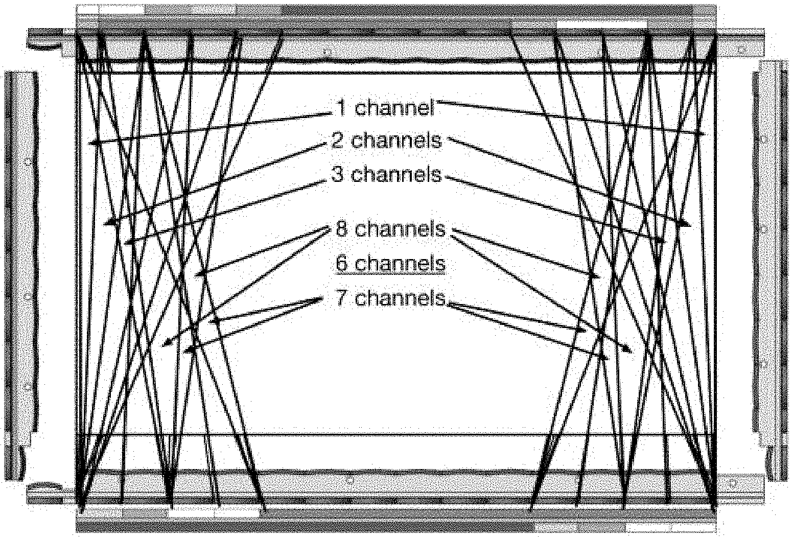
[0005] Reference is made to FIG. 2 which is a simplified illustration of a second prior art optical touchscreen, described in U.S. Pat. No. 9,063,614, entitled OPTICAL TOUCH SCREENS, and assigned to the assignee of the present invention. This touchscreen 902 is surrounded by lens arrays 304-307. Emitters 122-174 are arranged along two adjacent edges of the touchscreen, and detectors 224-278 are arranged along the remaining two edges. In contrast to lenses 300 and 301 in FIG. 1, lenses 305 and 306 are configured to spread light from each emitter to arrive at numerous detectors. Similarly, lenses 304 and 307 are configured such that each detector receives light from numerous emitters, e.g., .+-.8 channels per diode. FIG. 2 illustrates the dense mesh of detected light beams 422-474. Each emitter is synchronously activated with its corresponding detectors by processor 903. Processor 903 also stores the detector outputs and calculates touch locations based on these outputs.
[0006] The touchscreen system illustrated in FIG. 1, has relatively narrow light channels which provide good signal levels for touch detection. Furthermore, each light beam is shaped to provide signal gradients across the width of the beam. These signal gradients enable identifying precisely where within the beam the blocking object is located by comparing the amounts of blocked light detected by different emitter-detector pairs. Thus, this system provides excellent information from each light channel. In addition, this system works well with a large pitch (denoted p) between components (e.g., p is between 15 mm and 18 mm). However, this system is not optimal for suppressing ghost touches, as the vertical light beams are nearly parallel, as are the horizontal light beams.
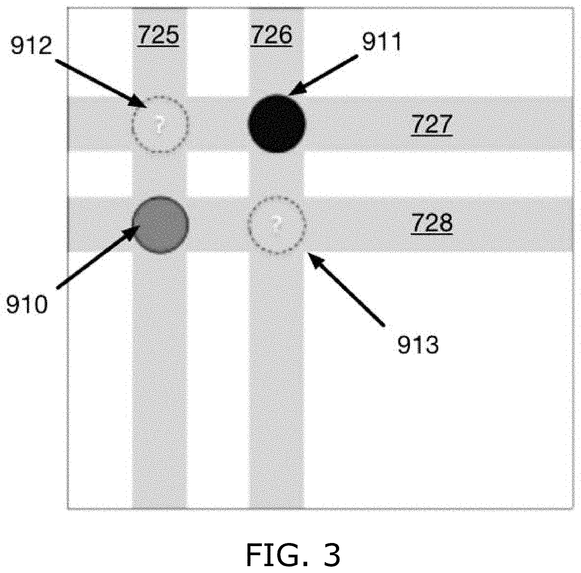
[0007] Reference is made to FIG. 3, which is a simplified illustration of the ghost touch problem. Blocked beams (detections) 725-728 create ambiguity as to which of locations 910-913 contain a touch object. In this case, the actual objects are located at locations 910 and 911.
[0008] The ghost touch problem exists in the touchscreen of FIG. 1. In contrast, the touchscreen system illustrated in FIG. 2 provides a range of different angles for the horizontal light beams and for the vertical light beams, e.g., .+-.20.degree.. This enables the system to suppress ghost touches well. This system works best with slightly more components, e.g., p.apprxeq.12.5 mm, making this system more expensive. The wide angle of the emitter beams provides lower signal levels for each emitter-detector pair, and furthermore, each emitter-detector light channel does not feature the signal gradients across the width of the beam as in the system of FIG. 1, making touch location calculation less exact. The touchscreen system of FIG. 2 also features many more light channels and therefore is more costly in terms of activating all of the emitter-detector channels and storing and processing the detection signals.
[0009] The following table summarizes the features of the systems illustrated in FIGS. 1 and 2.
TABLE-US-00001 TABLE I Features of touchscreen systems in FIGS. 1 and 2 FIG. 1 FIG. 2 good gradients no gradients good signal levels low signal levels few components intermediate number of components few channels many channels bad angles for ghost touch excellent angles for ghost touch suppression suppression
[0010] Publication No. US 2012/0188206 A1 (the "'206 publication"), entitled OPTICAL TOUCH SCREEN WTH TRI-DIRECTIONAL MICRO-LENSES is a publication of U.S. patent application Ser. No. 13/424,472, which is assigned to the assignee of the present invention. The '206 publication discusses an optical touchscreen in which each emitter beam is split into three separate beams, particularly with reference to FIGS. 83, 89, 90, 98 and 99 in the '206 publication. The motivation for the optical touchscreen in which each emitter beam is split into three separate beams, particularly with reference to FIGS. 83, 89, 90, 98 and 99 in the '206 publication went as follows. More information is needed in order to solve the ghost touch problem in the optical touchscreen of FIG. 1, namely the problem of trying to uniquely identify multiple touches based on insufficient positional data. The solution proposed in the '206 publication is to provide more detection channels, i.e., more grids of light beams. The more different the grids are, the better the information content. So, an added grid skewed at 45 degrees to the existing grid gives the most information without adding many channels.
[0011] However, the additional 45-degree grid requires that the detector photodiodes (PDs) be placed along all four edges of the screen, and thus, the configuration of FIG. 1 with LEDs on two edges of the touchscreen and PDs along the opposite edges of the touchscreen cannot be used. This leads to a configuration of alternating LEDs and PDs along the edges of the screen.
[0012] Then there is the choice of whether to use half-lenses on two of the four edges of the screen, or only standard lenses on all sides, namely, should the lenses along opposite edges of the screen be aligned, or shift-aligned as in FIG. 1. There are advantages to a shift-aligned configuration, as discussed inter alia in U.S. Pat. No. 9,471,170. However, a shift-aligned configuration is complicated in view of the additional 45-degree channels. Thus, an aligned configuration is required in consideration of the additional 45-degree channels.
[0013] The aligned configuration of lenses on opposite edges of the screen means that the LED and PD components on opposite edges of the screen are aligned as well. However, it had to be determined whether each LED is opposite another LED or opposite a PD. Assuming the central beam from each LED expands as it crosses the screen and therefore reaches three components along the opposite edge of the screen--if each LED is opposite another LED, then the central beam from one LED reaches two PDs. However, this causes trouble with bad information in the center, since the middle of this central beam is directed at an LED, not a PD. On the other hand, if each LED is opposite a PD, the channel is straight across from LED to PD, but the central beam spanning three opposite components arrives at only one PD (and the two LEDs on either side of that PD). In this case, there would be no overlap of channels and the possibilities of using interpolation of several signals (channels) would be severely limited. The benefits of interpolating overlapping channels is discussed inter alia in U.S. Pat. No. 9,471,170. The configuration aligning each LED opposite a PD and not featuring overlapping channels can be used for relatively large objects, as is indicated in '206 publication, paragraph [0332].
[0014] The way to provide overlapping channels is discussed in the '206 publication at paragraph [0333]; namely, interleaving different light channels using small facets to get an even distribution on the tri-directional pattern. The many small facets dilute the signal by spreading light in several directions and also by interleaving neighboring beams. Moreover, the system discussed in the '206 publication at paragraph [0333] is less flexible than the system discussed in U.S. Pat. No. 9,471,170, in terms of pitch width, as the '206 publication requires an even number of pitches on both sides of the screen. The signals are shaped by the focal length and the pitch, and although there is good information, it cannot be tailored much, and it looks like FIGS. 94 and 95 in the '206 publication.
[0015] The present invention addresses the shortcomings of the prior art. Other advantages of the present invention will become apparent from the description below.
SUMMARY
[0016] There is thus provided in accordance with an embodiment of the present invention an optical sensor for detecting locations of objects, including a plurality of lenses arranged along two opposite edges of a rectangular detection area, a circuit board mounted underneath the lenses, a plurality of light emitters mounted on the circuit board along a specific one of the two opposite edges of the rectangular detection area, each light emitter operable when activated to project light beams through a respective one of the lenses, wherein the lenses are configured to split the light beam projected from each light emitter into a plurality of divergent light beams directed across the rectangular detection area to respective pluralities of the lenses that are arranged along the edge of the rectangular detection area that is opposite the specific edge, wherein a light intensity of each directed beam is maximized along the center of the directed beam and a distribution of light intensity within each thus directed beam is known, a plurality of light detectors mounted on the circuit board along the edge of the rectangular detection area that is opposite the specific edge, each detector receiving the light beams directed across the rectangular detection area through a respective one of the lenses that are arranged along the edge of the rectangular detection area opposite that specific edge, and a processor receiving outputs from the light detectors, and calculating a location of an object in the rectangular detection area based on the known distribution of light intensity within each directed beam, and the received outputs.
[0017] According to further features in embodiments of the invention, the plurality of light emitters is shift-aligned with respect to the plurality of light detectors.
[0018] According to further features in embodiments of the invention, the lenses are designed such that light beams of different widths are directed by the lenses across the rectangular detection area.
[0019] According to further features in embodiments of the invention, the lenses are designed such that those of the lenses that are arranged near corners of the rectangular detection area direct light beams across the rectangular detection area that are narrower than the light beams directed across the rectangular detection area by the others of said lenses.
[0020] According to further features in embodiments of the invention, those of the lenses that are arranged near corners of the rectangular detection area are smaller than the others of the lenses.
[0021] According to further features in embodiments of the invention, those of the lenses that are arranged near corners of the rectangular detection area are designed to split the light beams from respective ones of the light emitters into fewer divergent light beams than the others of the lenses.
[0022] According to further features in embodiments of the invention, the lenses spread the pluralities of divergent light beams in fan-like shapes, each fan having an apex angle, wherein those of the lenses that are arranged near corners of the rectangular detection area generate fans of light beams having apex angles that are smaller than the apex angles of the fans of light beams generated by the others of the lenses.
BRIEF DESCRIPTION OF THE DRAWINGS
[0023] The present invention will be more fully understood and appreciated from the following detailed description, taken in conjunction with the drawings in which:
[0024] FIG. 1 is a simplified illustration of a first prior art optical touchscreen;
[0025] FIG. 2 is a simplified illustration of a second prior art optical touchscreen;
[0026] FIG. 3 is a simplified illustration of ghost touches;
[0027] FIG. 4 is a simplified illustration of the principles of calculating a touch location based on optical signals, in the optical touchscreen of FIG. 1, according to the present invention;
[0028] FIG. 5 is a simplified illustration of light from an emitter being split into three optical channels, in accordance with an embodiment of the present invention;
[0029] FIG. 6 is a simplified illustration of light from an emitter being split into two optical channels, in accordance with an embodiment of the present invention;
[0030] FIG. 7 is a simplified illustration of distinguishing an actual touch from a ghost touch, in accordance with embodiments of the present invention;
[0031] FIG. 8 is a simplified illustration of five different beams that may be created by a lens, in accordance with embodiments of the present invention;
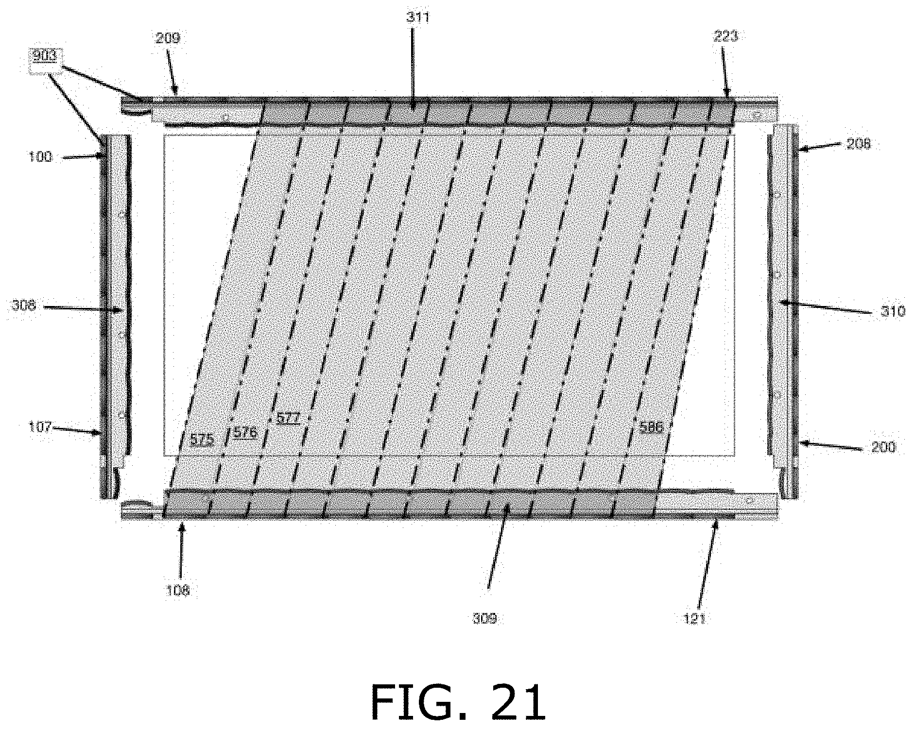
[0032] FIGS. 9-12 are illustrations of lenses used in an optical sensor, in accordance with an embodiment of the present invention;
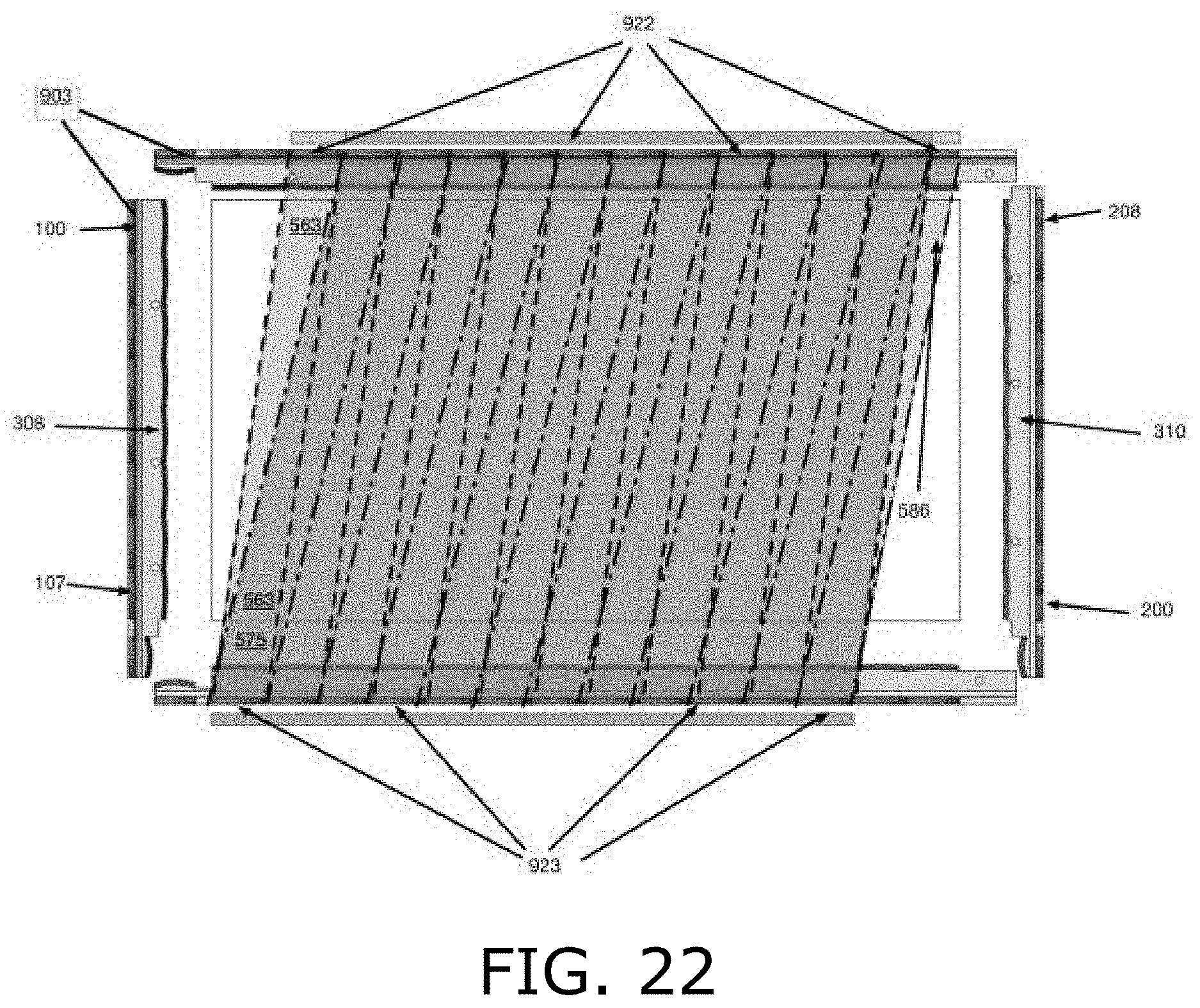
[0033] FIG. 13 is a simplified illustration of an optical touchscreen detection area, in accordance with an embodiment of the present invention;
[0034] FIGS. 14-16 are simplified illustrations of partially overlapping central light beams in an optical touchscreen, in accordance with an embodiment of the present invention;
[0035] FIGS. 17-19 are simplified illustrations of partially overlapping left-leaning light beams in an optical touchscreen, in accordance with an embodiment of the present invention;
[0036] FIGS. 20-22 are simplified illustrations of partially overlapping right-leaning light beams in an optical touchscreen, in accordance with an embodiment of the present invention;
[0037] FIGS. 23 and 24 are simplified illustrations of the number of overlapping light beams provided for touch detection in different portions of a touchscreen that features the beams of FIGS. 14-22, in accordance with an embodiment of the present invention;
[0038] FIGS. 25-27 are simplified illustrations of partially overlapping far left-leaning light beams in an optical touchscreen, in accordance with an embodiment of the present invention;
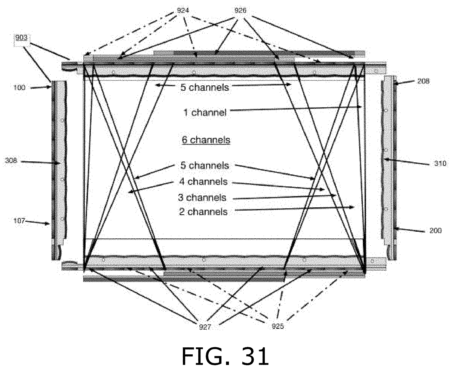
[0039] FIGS. 28 and 29 are simplified illustrations of partially overlapping far right-leaning light beams in an optical touchscreen, in accordance with an embodiment of the present invention;
[0040] FIGS. 30 and 31 are simplified illustrations of the number of overlapping light beams provided for touch detection in different portions of a touchscreen, featuring the beams of FIGS. 4, 14, 15 and 25-29, in accordance with an embodiment of the present invention;
[0041] FIG. 32 is a simplified illustration of an optical touchscreen having different optics for outer and inner beams crossing the screen, in accordance with an embodiment of the present invention;
[0042] FIG. 33A is a map showing different screen sections in an optical touchscreen, the sections having different numbers of overlapping detection channels, in accordance with an embodiment of the present invention;
[0043] FIG. 33B illustrates the different screen sections of FIG. 33A using text and arrows, in accordance with an embodiment of the present invention; and
[0044] FIG. 34 is a simplified illustration of the number of overlapping light beams provided for touch detection in different portions of a touchscreen for a touchscreen whose lenses are configured to split each emitter beam into two diverging beams, not three, in accordance with an embodiment of the present invention.
[0045] In the disclosure and figures, the following numbering scheme is used. Like numbered elements are similar but not necessarily identical.
TABLE-US-00002 TABLE II Elements of Figures Type of element Numbering range FIGS. light emitters 100-199 1, 2, 4-6, 8, 13-32, 34 light detectors 200-299 1, 2, 4-6, 13-32, 34 lenses 300-399 1, 2, 4-6, 9-32, 34 light beams 400-699 1, 2, 4-6, 8, 14, 15, 17-23, 25-30 light detection 700-799 3-6 other items 900-999 1-5, 7-9, 13-32, 34
DETAILED DESCRIPTION
[0046] The following table summarizes certain features of a touchscreen according to the present invention, in relation to features of the prior art touchscreens illustrated in FIGS. 1 and 2.
TABLE-US-00003 TABLE III Features of the Present Invention FIG. 1 Present invention FIG. 2 good gradients good gradients no gradients good signal levels intermediate signal low signal levels levels few components few components intermediate number of components few channels intermediate no. many channels channels bad angles for ghost excellent angles for excellent angles for touch suppression ghost touch ghost touch suppression suppression
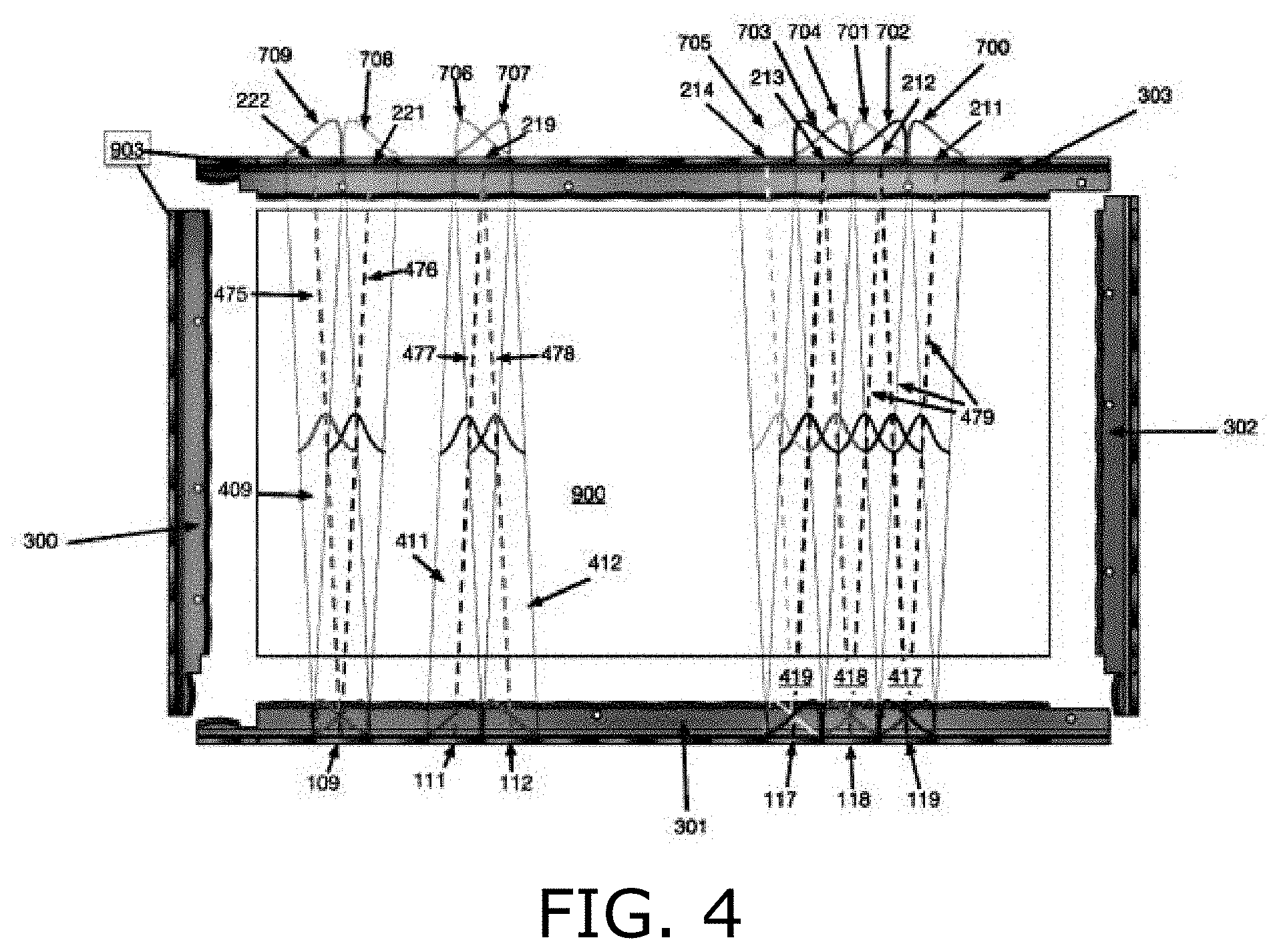
[0047] Reference is made to FIG. 4, which is a simplified illustration of the principles of calculating a touch location based on optical signals, in the optical touchscreen of FIG. 1, according to the present invention. FIG. 4 illustrates signal gradients in a touchscreen embodiment. Emitter 109 projects vertical light beam 409 across detection area 900, detected by neighboring detectors 221 and 222. Specifically, beam portion 475 is detected by detector 222 and beam portion 476 is detected by detector 221. Beam portion 475 is shown as a parallelogram that extends from the lens at emitter 109 to the lens at detector 222, and beam portion 476 is shown as a parallelogram that extends from the lens at emitter 109 to the lens at detector 221; the dashed lines in beam portions 475 and 476 indicate the center of each beam portion. Lenses 301 shape beam 409 such that maximum intensity is along the center of the beam, and the intensity gradient is reduced toward the edges of the beam, as represented by detections 709 and 708. Lenses 303 are similar to lenses 301 and collect the incoming light onto the detectors. When an object blocks part of beam portion 475 from reaching detector 222 and part of beam portion 476 from reaching detector 221, the location of the object along the width of beam 409 is determined by comparing the detections at detectors 221 and 222: if the detections are equal, the object is along the beam's central axis, and if the detections are unequal, their ratio indicates how far the object is shifted to one side of the beam's center.
[0048] FIG. 4 also shows detector 219 receiving light from two emitters 111 and 112, specifically, portion 477 of the beam from emitter 111 and portion 478 of the beam from emitter 112 arrive at detector 219. As beam portions 477 and 478 overlap, the system determines where along the width of the overlap an object is positioned by comparing the detections of emitter-detector pair 111-219 with the detections of emitter-detector pair 112-219.
[0049] FIG. 4 shows vertical beams 417-419 from emitters 117-119 to detectors 211-214. Overlapping detected portions 479 of these beams illustrate that an object placed in detection area 900 will be detected by at least two emitter-detector pairs, i.e., {(e,d), (e,d+1)} or {(e,d), (e+1,d)}, where e and e+1 are two neighboring emitters and d and d+1 are two neighboring detectors. As explained above, the overlapping detections and the shaped light beams provide signal gradients that enable precise calculations of locations of objects touching the screen, or otherwise entering the plane of these light beams, by comparing the magnitude of detections of a single object by several emitter-detector pairs. One method of comparing these detections is by interpolation. The synchronized activation of emitter-detector pairs is controlled by processor 903. Processor 903 also stores detector outputs and calculates a location of a detected object based on those outputs.
[0050] FIG. 4 shows that the emitter lenses along two edges of detection area 900 are shift-aligned with the detector lenses along the opposite edges of detection area 900, and the beam from each emitter detected by two opposite detectors can be expressed as being detected by detectors that are offset+/-0.5 lens pitch from opposite the emitter. According to the present invention, light from each emitter is split into several beams detected by additional pairs of detectors to provide additional detection channels and more angles for ghost touch suppression.
[0051] Thus, in certain embodiments of the invention, a first additional beam is directed towards detectors, along the opposite edge of the detection area, that are offset 1.5 and 2.5 lens pitches from opposite the emitter, and a second additional beam is directed towards detectors, along the opposite edge of the detection area, that are offset -1.5 and -2.5 lens pitches from opposite the emitter. These additional beams are illustrated in FIGS. 17-22. When all three sets of beams are provided, namely, the initial beam directed at the detectors that are offset+/-0.5 lens pitches from opposite the emitter, plus the two additional beams, six sets of detection channels are provided. This is illustrated in FIGS. 23 and 24.
[0052] In other embodiments of the invention, different additional beams are used to provide a wider range of angles for ghost touch suppression; namely, a first additional beam is directed towards neighboring detectors that are offset 3.5 and 4.5 lens pitches from opposite the emitter, and a second additional beam is directed towards detectors that are offset -3.5 and -4.5 lens pitches from opposite the emitter. These additional beams are illustrated in FIGS. 25-29. When these beams are provided together with the initial beam directed at the detectors that are offset+/-0.5 lens pitches from the emitter, six sets of detection channels are provided, as illustrated in FIGS. 30 and 31. Still other embodiments of the invention provide additional beams with larger emitter-detector offsets, as illustrated in FIGS. 25-29, but provide additional beams with smaller emitter-detector offsets near the edges of the detection area, as illustrated in FIGS. 32 and 33.
[0053] Reference is made to FIG. 5, which is a simplified illustration of light from an emitter being split into three optical channels, in accordance with an embodiment of the present invention. FIG. 5 illustrates splitting each emitter beam into three separate, diverging beams 484-486, each separate beam being shaped with a gradient as described hereinabove with respect to FIG. 4, such that the highest intensity is along the center of each of separate beam, and the light intensity is reduced from the center of the beam outward. These split, shaped beams are formed by lenses 309, and similar lenses 311 are provided at the detectors for directing beams in each of the three directions onto each detector. Each of beams 484-486 arrives at two detectors. Specifically, beam 484 arrives at detectors 214 and 215; beam 485 arrives at detectors 212 and 213; and beam 486 arrives at detectors 210 and 211. As such, the minimum angle between beams 484 and 485, and between beams 485 and 486, is
.theta. min = tan - 1 .function. ( 2 .times. p L ) ##EQU00001##
where p is the pitch between neighboring components and L is the distance between the row of emitters and the opposite row of detectors.
[0054] Although FIG. 5 shows each beam split into three separate, shaped beams, in other embodiments of the invention each beam is split into only two separate, shaped beams, providing a greater amount of light for each separate beam.
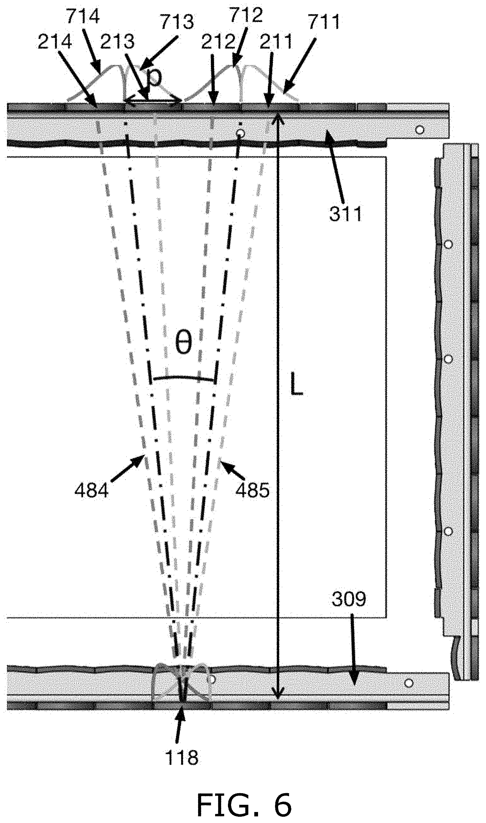
[0055] Reference is made to FIG. 6 illustrating light from emitter 118 being split into two separate beams 484 and 485, each separate beam being shaped with a gradient as described hereinabove with respect to FIGS. 4 and 5, such that the highest intensity is along the center of each separate beam, and the light intensity is reduced from the center of the beam outward. These split, shaped beams are formed by lenses 309, and similar lenses 311 are provided at the detectors for directing beams in each of the two directions onto the detectors. Each of beams 484 and 485 arrives at two detectors. Specifically, beam 484 arrives at detectors 213 and 214, and beam 485 arrives at detectors 211 and 212. As such, the minimum angle between beams 484 and 485, is
.theta. min = tan - 1 .function. ( 2 .times. p L ) ##EQU00002##
where p is the pitch between neighboring components and L is the distance between the row of emitters and the opposite row of detectors.
[0056] Beams 484 and 485 are both projected by emitter 118. Lenses 309 split and shape these two beams and direct them at detectors 211-214, via lenses 311. The detections at detectors 211-214 are indicated by sloping curves 711-714. The maximum intensity for each beam is along its center, indicated by the maximum of each curve 711-714 being near the beam center and declining outward.
[0057] Reference is made to FIG. 7, which is a simplified illustration of distinguishing an actual touch from a ghost touch, in accordance with embodiments of the present invention. FIG. 7 shows two touches in detection area 904 and illustrates that, in a system with two diverging beams for each emitter as illustrated in FIG. 6, the locations of the four candidate touch points indicated by blocked left-sloping beams 484 of FIG. 6 are slightly different than the four candidate touch points indicated by the blocked right-sloping beams 485 of FIG. 6. Arrows 931 indicate the directions of the right-sloping vertical and horizontal beams, and arrows 932 indicate the directions of the left-sloping vertical and horizontal beams. The right-sloping beams indicate possible touch locations 910, 911, 912' and 913', and the left-sloping beams indicate possible touch locations 910, 911, 912'' and 913''. Thus, locations 910 and 911 at which actual objects are present are identical for both sets of beams, whereas the ghost locations 912 and 913 are not the same. Accordingly, by comparing the touch locations indicated by the different sets of beams, it is determined that locations that are identical for the different sets of beams are actual touch locations, and locations that are not identical for the different sets of beams are not touch locations. Put differently, by combining the touch detections from all of the beams, it is determined that locations whose detections by different sets of beams are concentrated at specific locations are actual touch locations, and locations for which the combined detections from different sets of beams are more diffuse are not touch locations. Splitting each emitter beam into three diverging beams provides a more robust solution to the ghost touch problem. In addition, the larger the angle between the diverging beams as discussed hereinbelow, the more robust the elimination of ghost touches.
[0058] Thus, splitting the light from each emitter into two or three beams provides different angled beams that resolve many ghost touch situations that the touchscreen of FIG. 1 cannot similarly resolve. In addition, the split beams cover most of the display area with many different overlapping beams, providing greater resolution and precision for calculating touch locations.
[0059] Reference is made to FIG. 8, which is a simplified illustration of five different beams that may be created by a lens, in accordance with embodiments of the present invention. FIG. 8 shows five different beams 487-491 that may be created from emitter 118 by a lens. As discussed hereinabove, each of the five beams is shaped to have maximum intensity along the center with the intensity decreasing further from the central line. This beam shape enables identifying where within the width of the beam an object is located based on the amount of light it blocks. Each beam is directed toward a pair of detectors at the opposite edge of the detection area. In certain embodiments of the invention, each lens creates three of these five beams. In certain embodiments discussed hereinbelow the lenses farther from the corners of detection area 904 generate the central beam 489 and the two outer beams 487 and 491, in order to provide beams separated by large angles, whereas lenses closer to the corners of the detection area are configured to generate the three inner beams 488-490, as an outer beam 487 or 491 would be directed outside detection area 904 and would not reach a detector on the opposite edge.
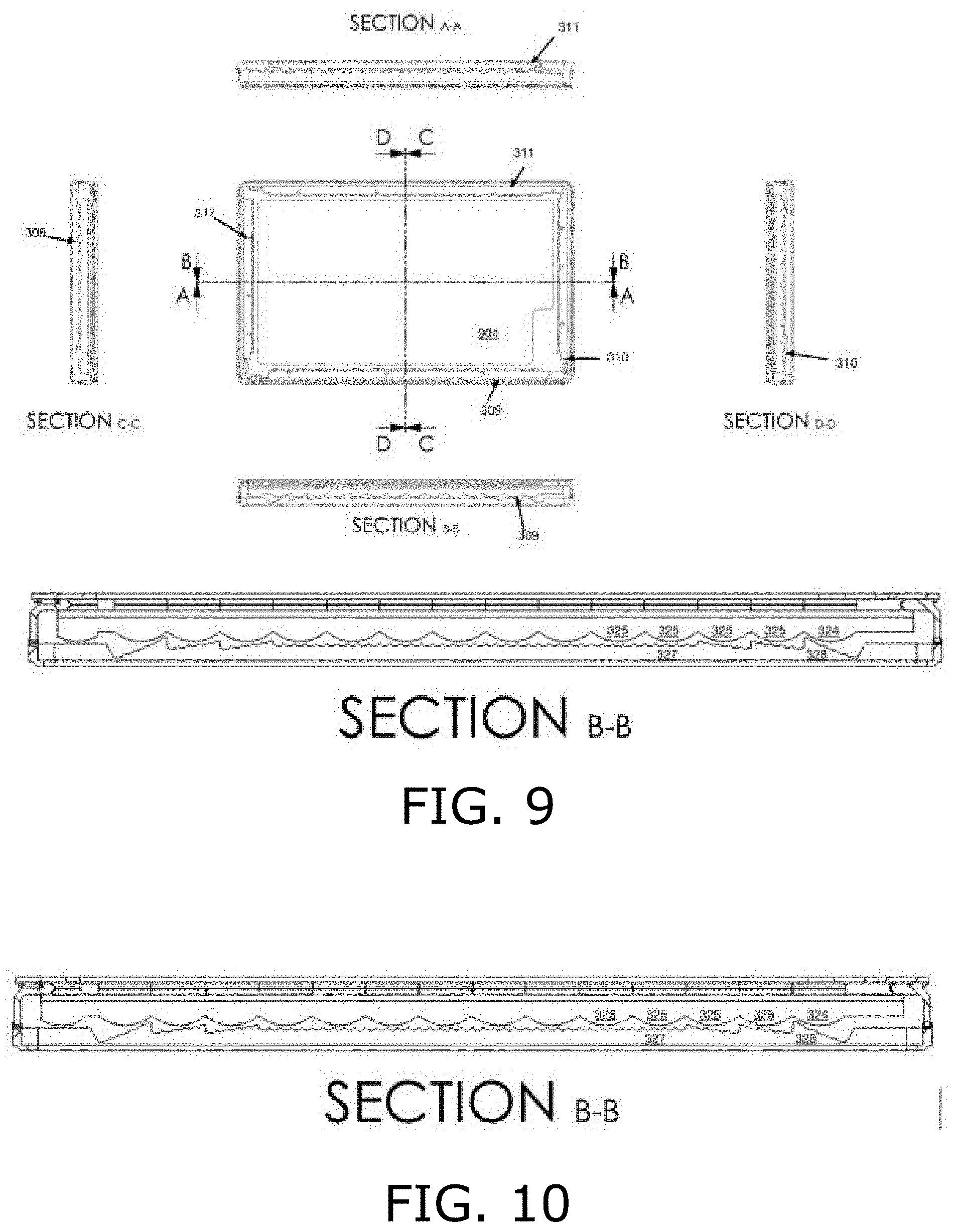
[0060] Reference is made to FIGS. 9-12, which are illustrations of lenses used in an optical sensor, in accordance with an embodiment of the present invention. FIG. 9 shows a touchscreen having detection area 904 surrounded by lens structures 309-312, and cross-sections thereof.
[0061] FIG. 10 shows lens structure 309 of the touchscreen in FIG. 9. This lens structure is mounted above a series of light emitters, and it splits the light from each emitter into three separate beams. FIG. 10 shows focusing lenses 324 and 325, and lenses 327 and 328 that split the light into separate beams.
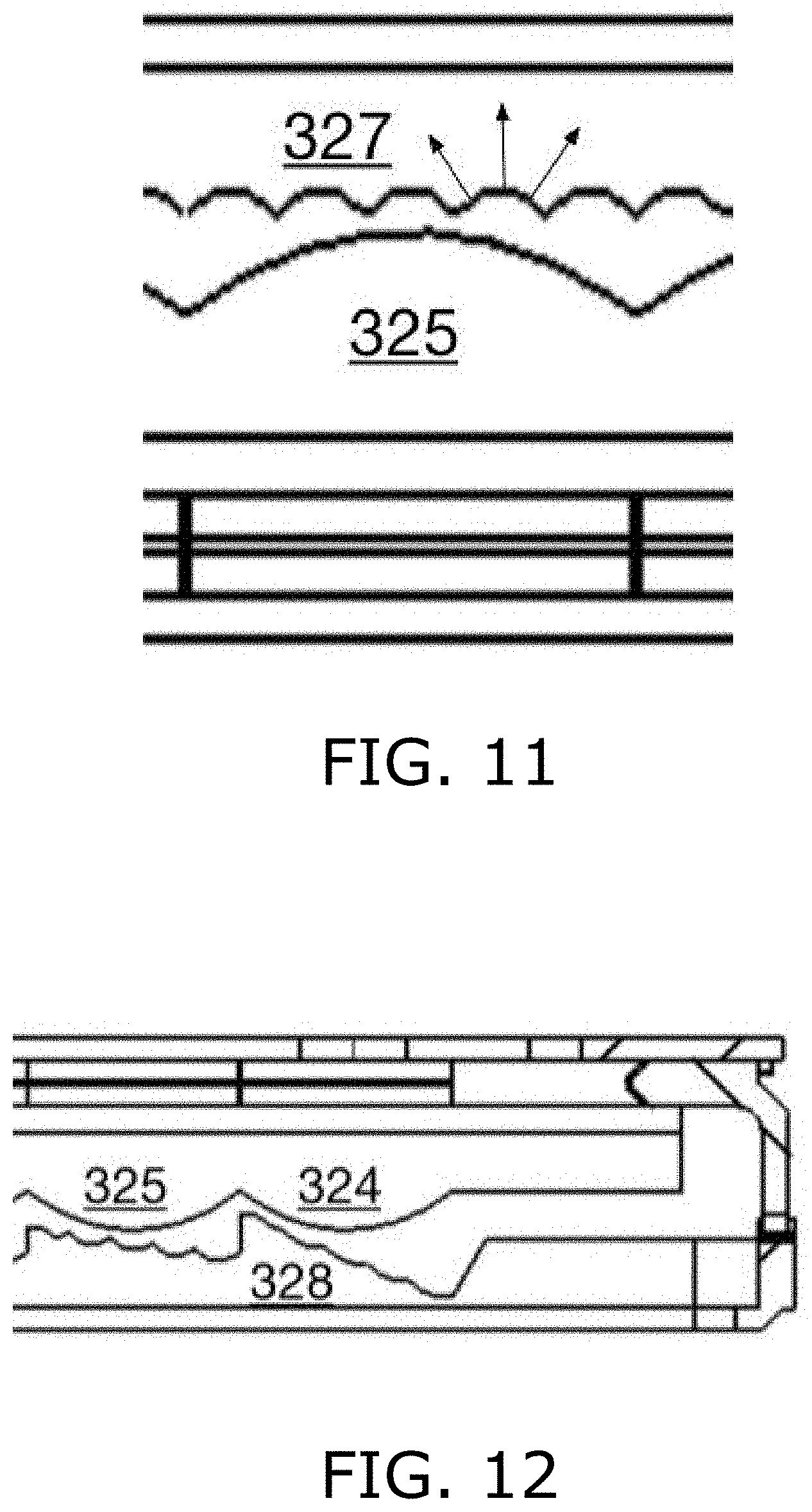
[0062] FIG. 11 shows one of focusing lenses 325 and the associated portion of lens 327, having a repeating three-facet pattern indicated by three arrows that split the light into three separate beams. In sensors configured with two beams for each emitter instead of three, lens 327 has a repeating sawtooth pattern of facets in two directions to create two diverging beams.
[0063] FIG. 12 shows a section of lens structure 309 near the corner of the touch detection area. This section includes focusing lens 324 and associated lens 328 for splitting the light. Because this lens is near a corner of the detection area, lens 328 is configured to direct the light so that the rightmost beam arrives at a detector on the opposite edge of the detection area, and in some embodiments this section splits the light into fewer beams than the other sections. In certain embodiments, this section of lenses is smaller than the others and is thus configured to create more concentrated beams of light than the other sections because an edge of the screen is covered by fewer overlapping beams than other screen sections.
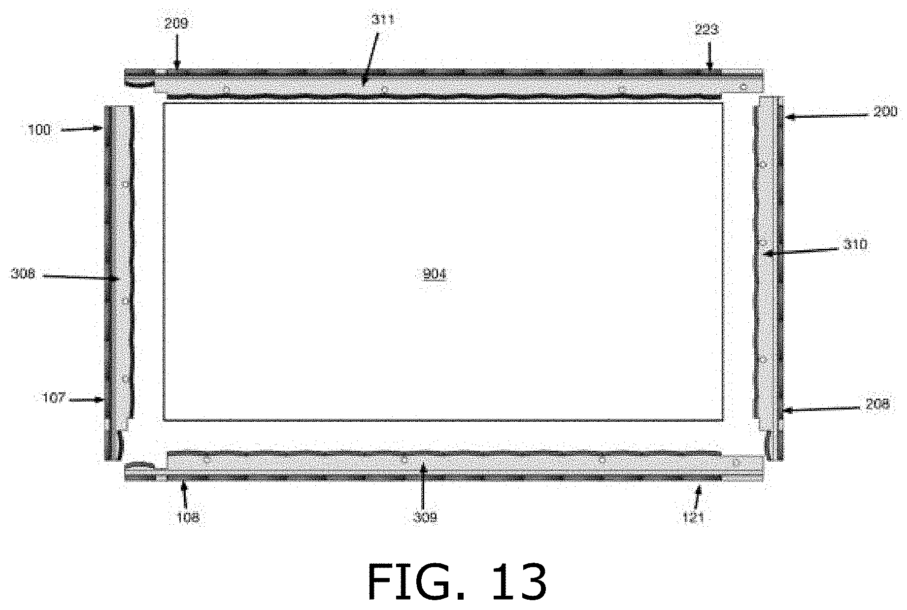
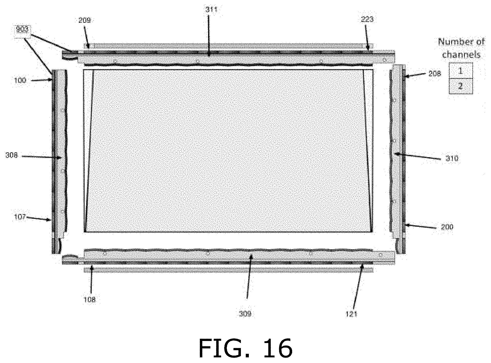
[0064] Reference is made to FIG. 13, which is a simplified illustration of an optical touchscreen detection area, in accordance with an embodiment of the present invention. FIG. 13 shows a frame of lenses 308-311 surrounding detection area 904, in accordance with an embodiment of the present invention. Each lens in lens array 308 directs beams from a respective one of emitters 100-107 across detection area 904. Each lens in lens array 310 directs incoming light onto a respective one of detectors 200-208. The number of detectors 200-208 is greater than the number of opposite emitters 100-107, as the emitters and detectors are shift-aligned. This is evident from lens array 310 which features seven full-lenses and two half-lenses at either end of array 310, whereas lens array 308 features eight full lenses. Each lens in lens array 309 directs light beams from a respective one of emitters 108-121 across detection area 904. Each lens, or half-lens at either end, in lens array 311 directs incoming light onto a respective one of detectors 209-223. The number of detectors 209-223 is greater than the number of opposite emitters 108-121, as the emitters and detectors are shift-aligned. This is evident from lens array 311 which features thirteen full-lenses and two half-lenses at either end of array 311, whereas lens array 309 features fourteen full lenses. As discussed hereinabove with reference to FIGS. 5 and 6, light from each emitter is split into multiple separate shaped beams, and each beam arrives at two neighboring detectors along the opposite edge of detection area 904. An emitter-detector pair refers to a portion of the light beam from one emitter that arrives at one opposite detector. The following figures illustrate these portions to indicate the various emitter-detector pairs providing detection information in accordance with embodiments of the present invention.
[0065] Reference is made to FIGS. 14-16, which are simplified illustrations of partially overlapping central light beams in an optical touchscreen, in accordance with an embodiment of the present invention. FIG. 14 shows a first set of beam portions 500-513, namely, the left-hand portion of the central beam from each emitter. These beam portions provide a first set of emitter-detector detection channels.
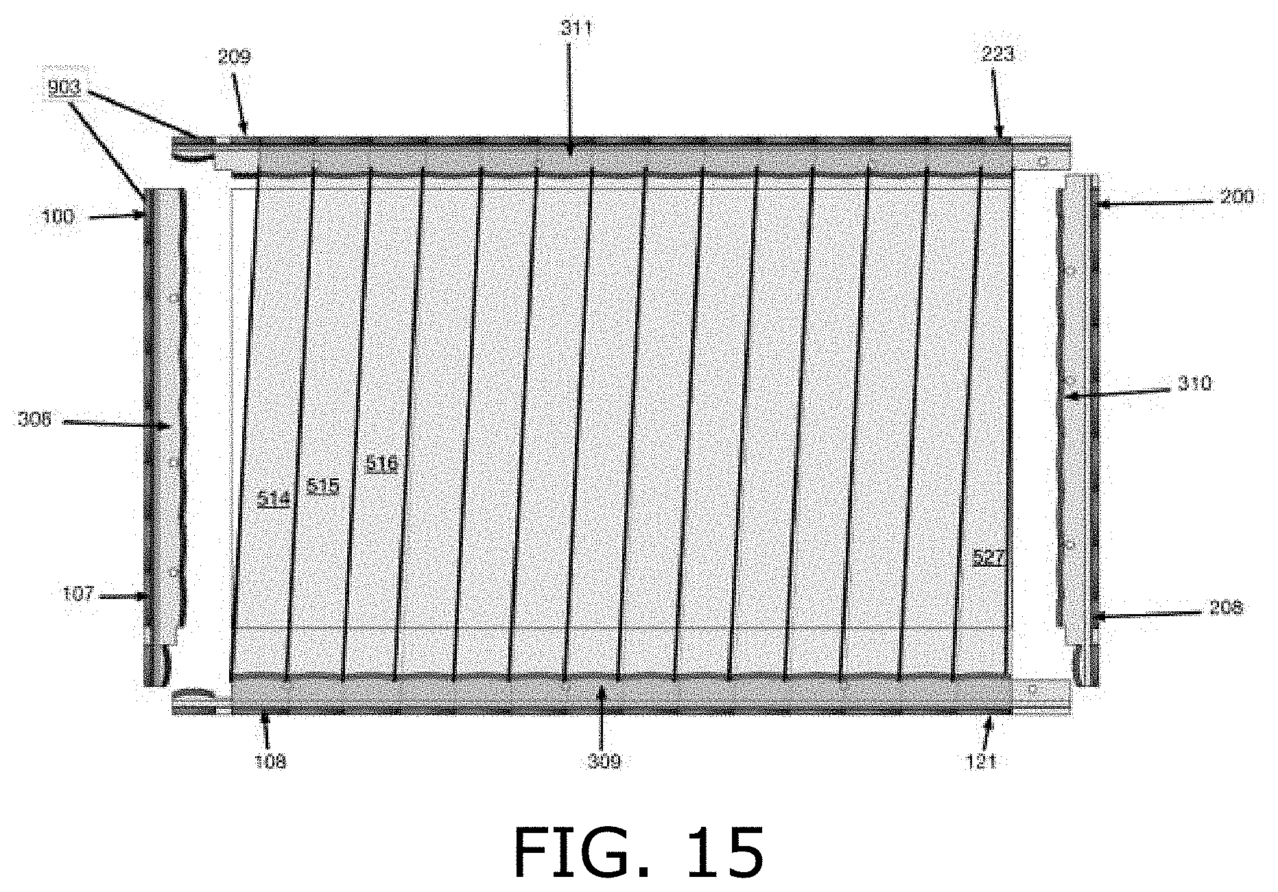
[0066] FIG. 15 shows a second set of beam portions 514-527, namely, the right-hand portion of the central beam from each emitter. These beam portions provide a second set of emitter-detector detection channels.
[0067] FIG. 16 shows coverage of detection area 904 by beam portions 500-527 shown in FIGS. 14 and 15. FIG. 16 indicates that most of detection area 904 is covered by two beam portions; i.e., two detection channels, except for two narrow triangular sections at the outer edges of detection area 904, which are only covered by one detection channel. A similar coverage map exists for the horizontal beams traveling from emitters 100-107 to detectors 200-208.
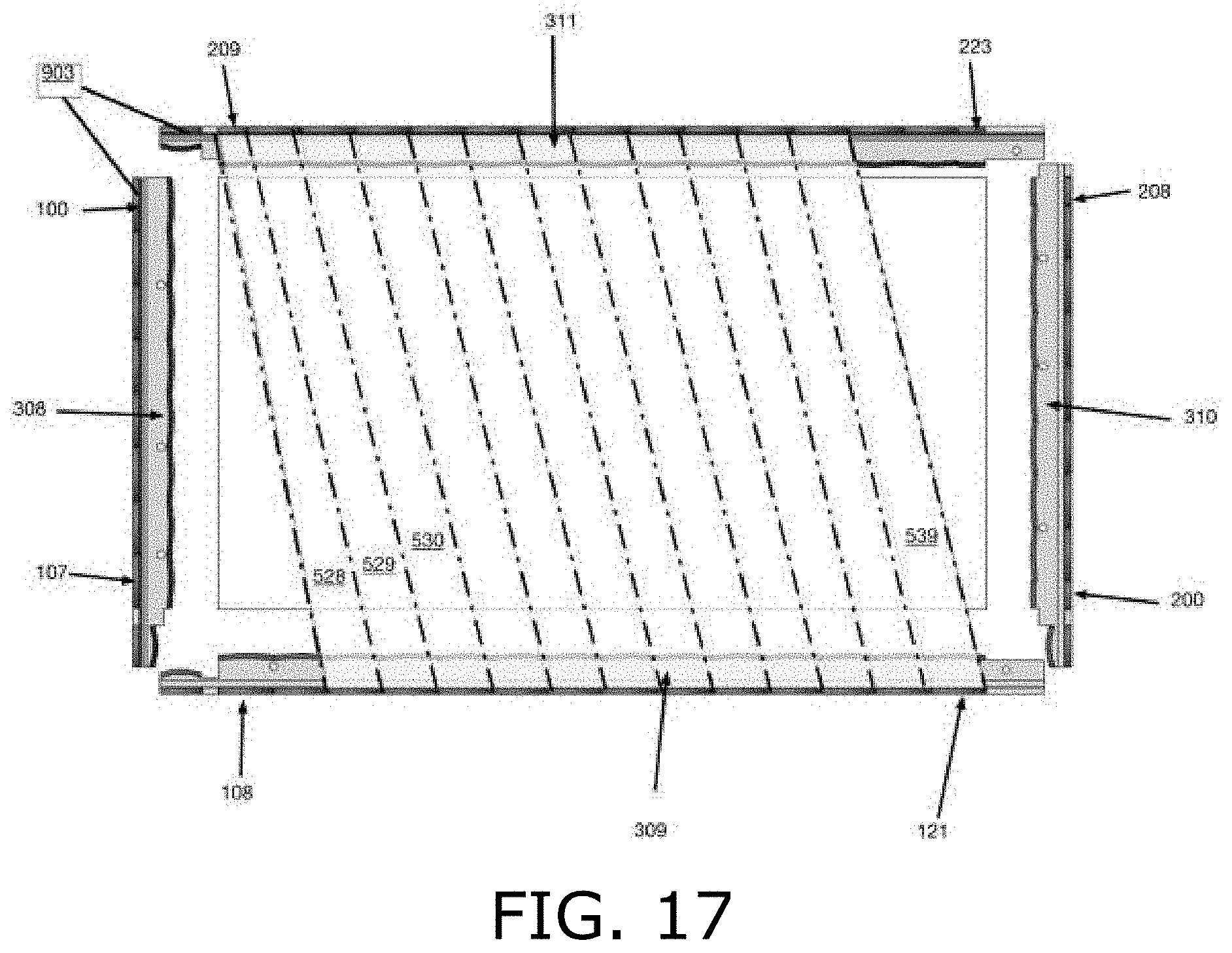
[0068] Reference is made to FIGS. 17-19, which are simplified illustrations of partially overlapping left-leaning light beams in an optical touchscreen, in accordance with an embodiment of the present invention. FIG. 17 shows a third set of beam portions 528-539, namely, the left-hand portion of the left-leaning beam from each emitter. These beam portions provide a third set of emitter-detector detection channels.
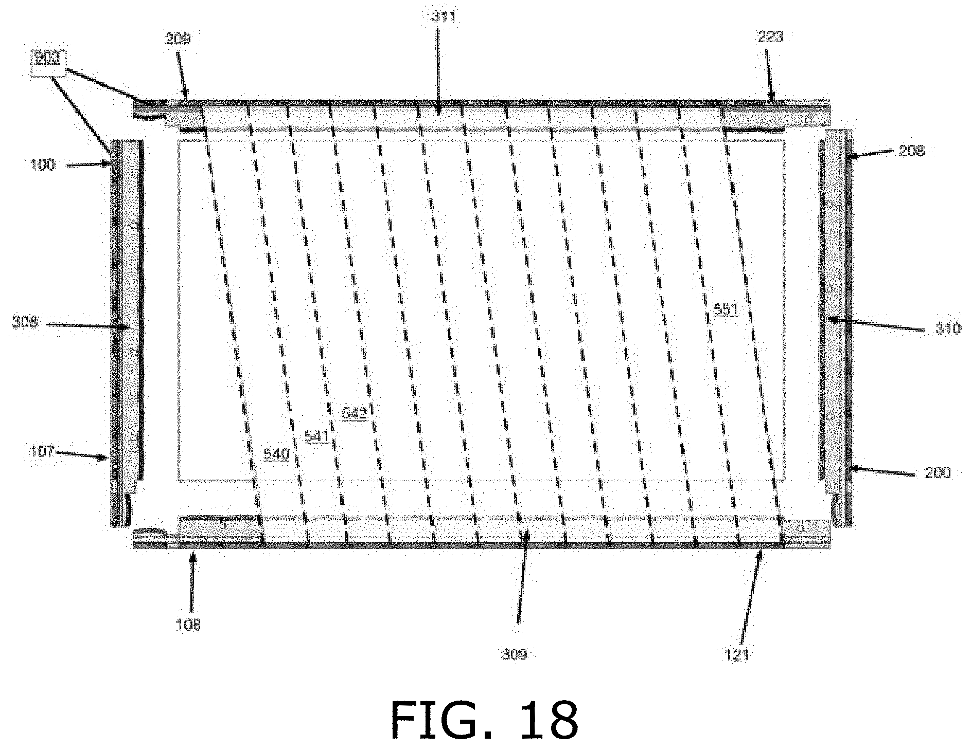
[0069] FIG. 18 shows a fourth set of beam portions 540-551, namely, the right-hand portion of the left-leaning beam from each emitter. These beam portions provide a fourth set of emitter-detector detection channels.
[0070] FIG. 19 shows additional coverage of detection area 904 by the left-leaning beams; i.e., beam portions 528-551 shown in FIGS. 17 and 18. FIG. 19 indicates that most of detection area 904 is covered by two beam portions; i.e., two detection channels, except for a first narrow triangular section along the outer left edge of left-leaning beam 528, and a wider triangular section at the outer right edge of left-leaning beam 551, which are only covered by one detection channel. FIG. 19 also illustrates two triangular sections at the outer edges of detection area 904 that are not covered by these left-leaning beams. A similar coverage map exists for the horizontal beams traveling from emitters 100-107 to detectors 200-208. FIG. 19 indicates series 921 of emitters and series 920 of detectors that are active in providing the illustrated detection channels 528-551.
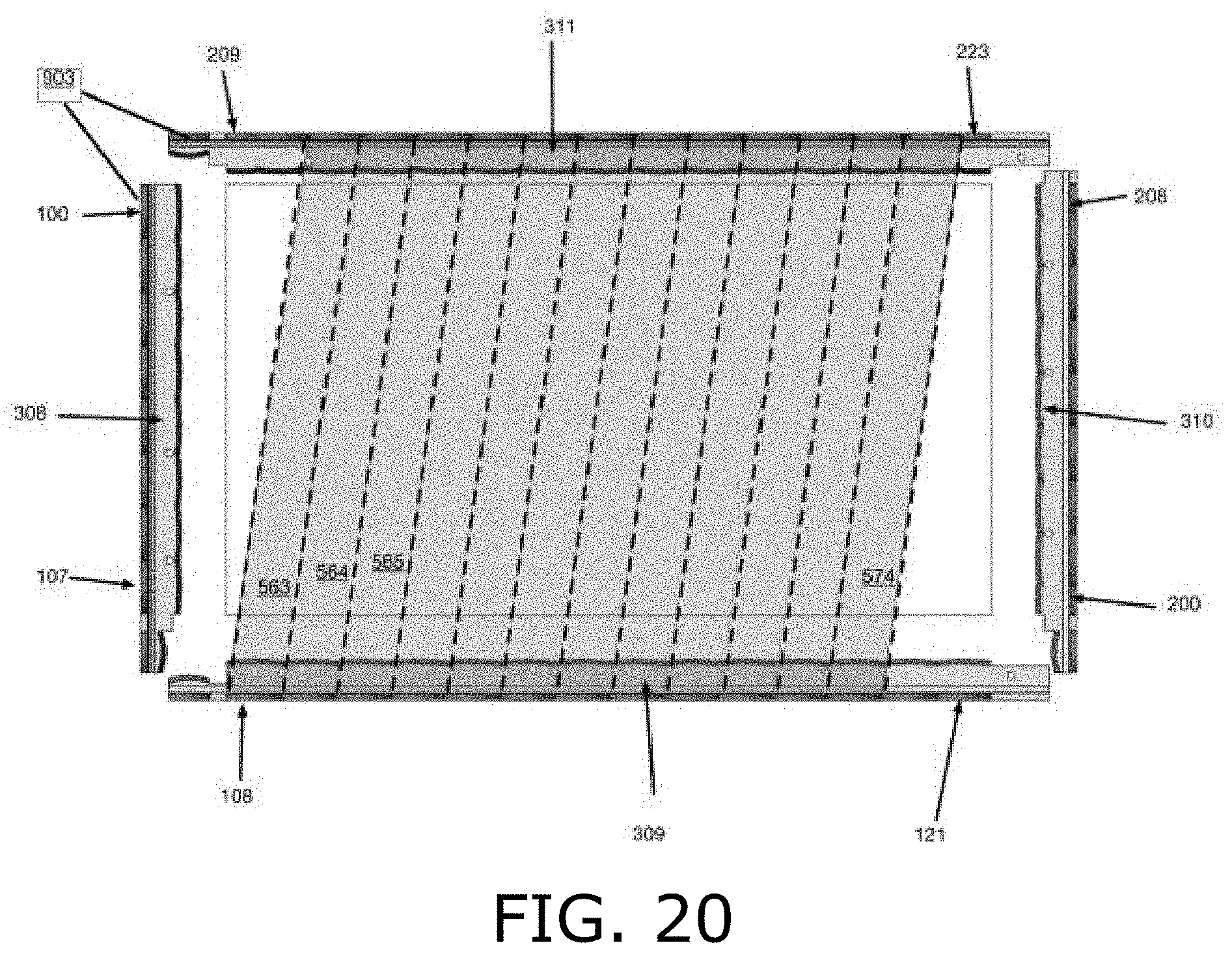
[0071] Reference is made to FIGS. 20-22, which are simplified illustrations of partially overlapping right-leaning light beams in an optical touchscreen, in accordance with an embodiment of the present invention. FIG. 20 shows a fifth set of beam portions 563-574; namely, the left-hand portion of the right-leaning beam from each emitter. These beam portions provide a fifth set of emitter-detector detection channels.
[0072] FIG. 21 shows a sixth set of beam portions 575-586, namely, the right-hand portion of the right-leaning beam from each emitter. These beam portions provide a sixth set of emitter-detector detection channels.
[0073] FIG. 22 shows additional coverage of detection area 904 by the right-leaning beams; i.e., beam portions 563-586 shown in FIGS. 20 and 21. FIG. 22 indicates that most of detection area 904 is covered by two beam portions; i.e., two detection channels, except for a first narrow triangular section along the outer right edge of right-leaning beam 586, and a wider triangular section at the outer left edge of right-leaning beam 563, which are only covered by one detection channel. FIG. 22 also illustrates two triangular sections at the outer edges of detection area 904 that are not covered by these right-leaning beams. A similar coverage map exists for the horizontal beams traveling from emitters 100-107 to detectors 200-208. FIG. 22 indicates series 923 of emitters and series 922 of detectors that are active in providing the illustrated detection channels 563-586.
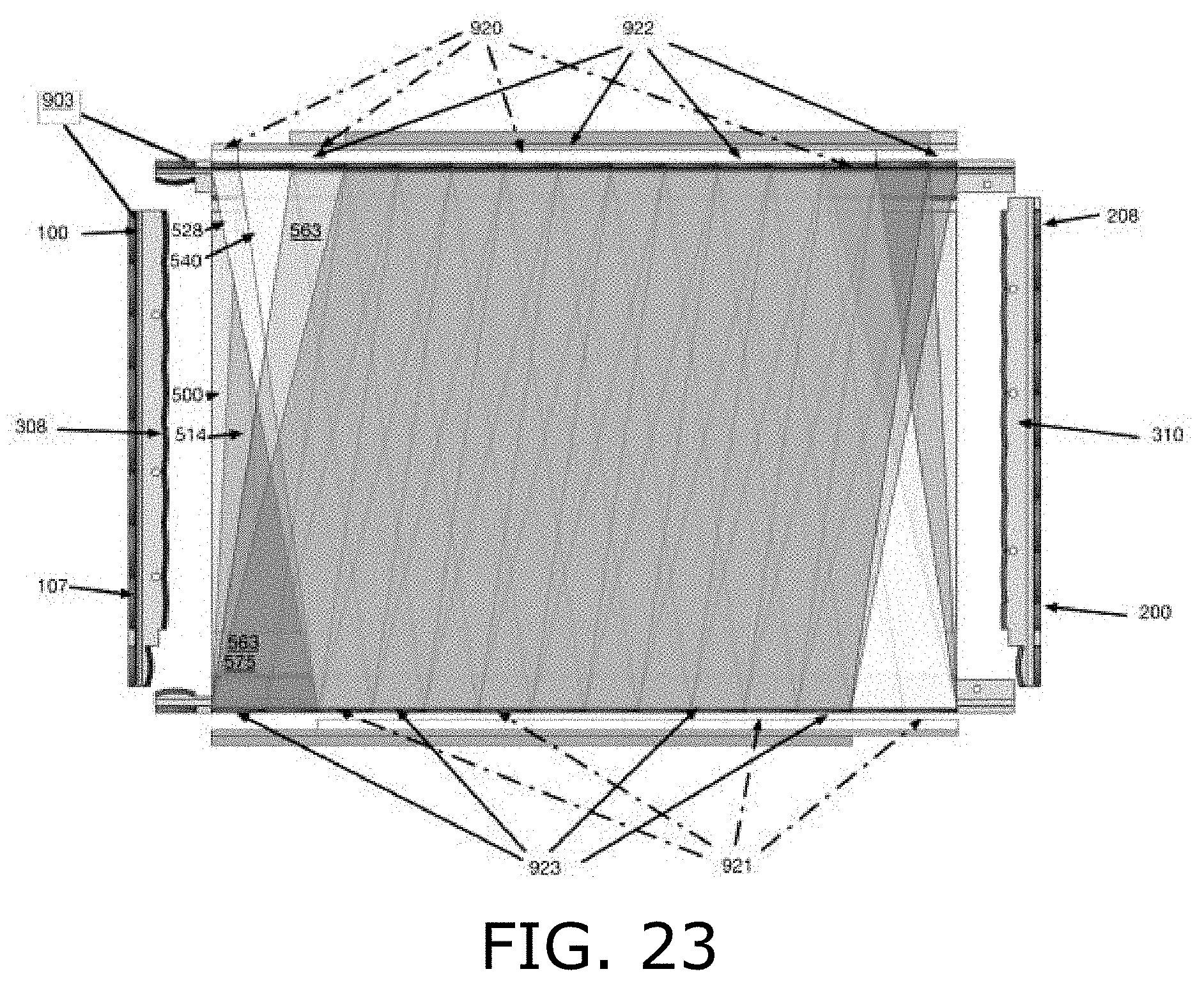
[0074] Reference is made to FIGS. 23 and 24, which are simplified illustrations of the number of overlapping light beams provided for touch detection in different portions of a touchscreen that features the beams of FIGS. 14-22, in accordance with an embodiment of the present invention. FIG. 23 shows coverage of detection area 904 when all six sets of detection channels discussed hereinabove with reference to FIGS. 14-22 are combined. The central portion of detection area 904 is covered by multiple detection signals from all six sets of detection beams--the central, left-leaning and right-leaning beams. However, FIG. 23 indicates areas near the edges of detection area 904 that are covered by only three or four sets of detection signals, and areas covered by only one or two detection signals.
[0075] FIG. 24 indicates the number of detection channels covering different portions of detection area 904, in the embodiment illustrated in FIG. 23. The number of detection channels varies between 1-6. A similar map of detection channels applies to the horizontal beams, from emitters 100-107 to detectors 200-208.
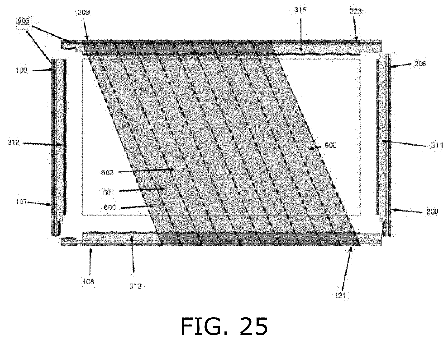
[0076] Reference is made to FIGS. 25-27, which are simplified illustrations of partially overlapping far left-leaning light beams in an optical touchscreen, in accordance with an embodiment of the present invention. FIG. 25 illustrates detection channels between each emitter and a respective detector that is offset 4.5 lens pitches from opposite the emitter;
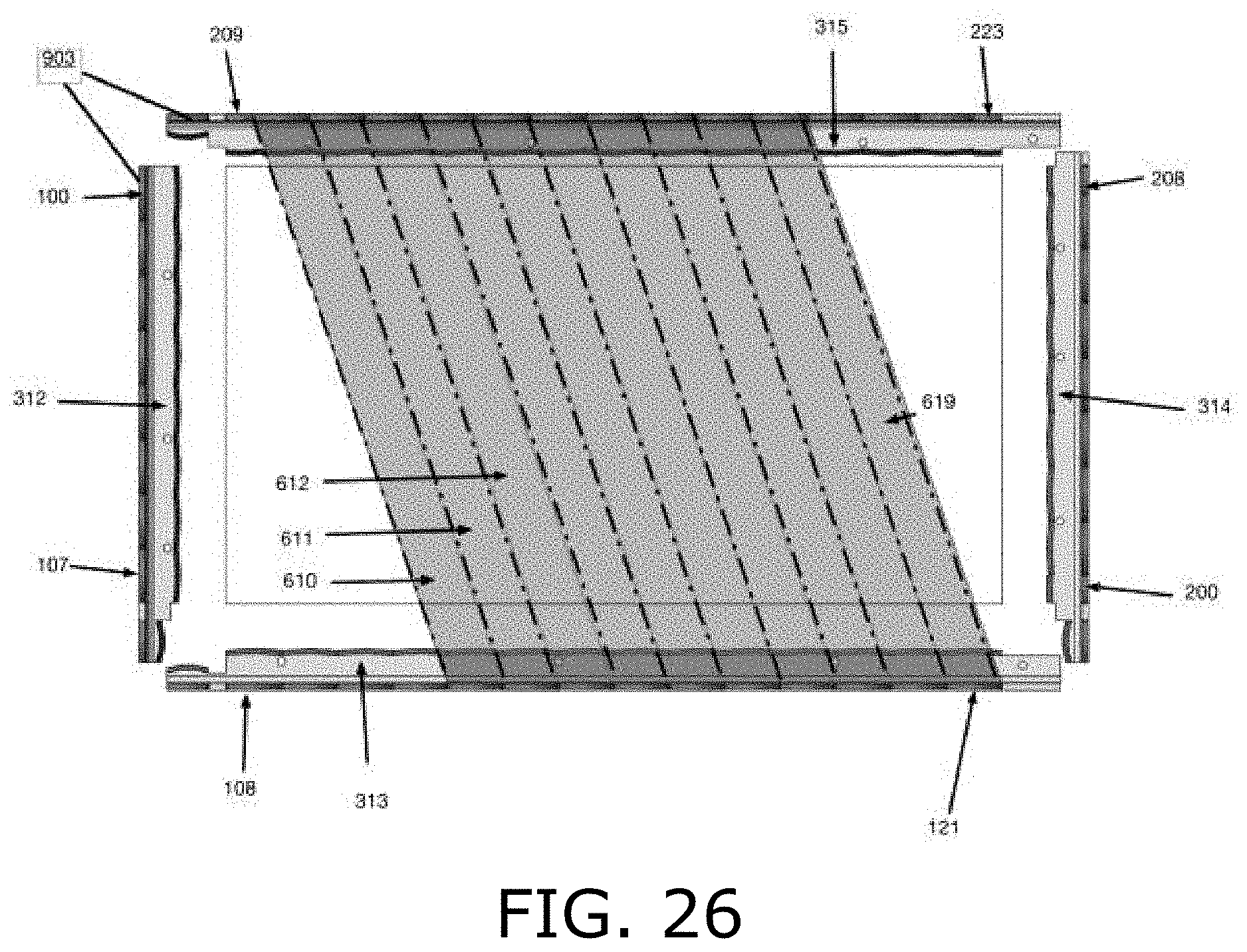
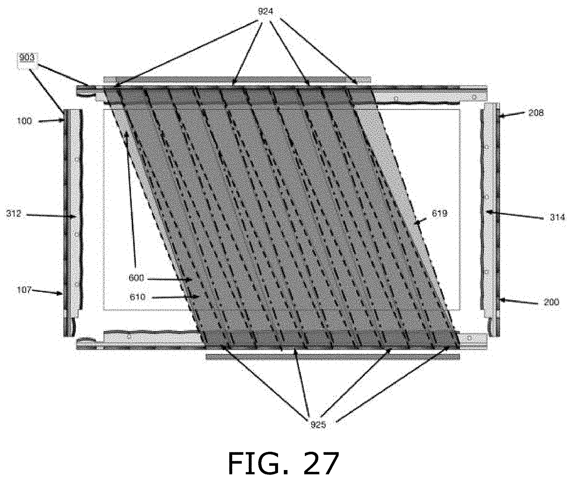
[0077] FIG. 26 illustrates detection channels between each emitter and a respective detector that is offset 3.5 lens pitches from opposite the emitter; and FIG. 27 illustrates the combined area covered by these two detection channels. FIG. 27 indicates series 925 of emitters and series 924 of detectors that are active in providing the illustrated detection channels 600-619.
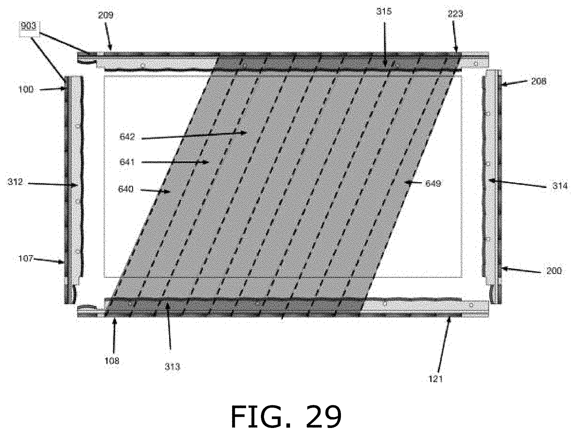
[0078] Reference is made to FIGS. 28 and 29, which are simplified illustrations of partially overlapping far right-leaning light beams in an optical touchscreen, in accordance with an embodiment of the present invention. FIG. 28 illustrates detection channels between each emitter and a respective detector that is offset -3.5 lens pitches from opposite the emitter; FIG. 29 illustrates detection channels between each emitter and a respective detector that is offset -4.5 lens pitches from opposite the emitter.
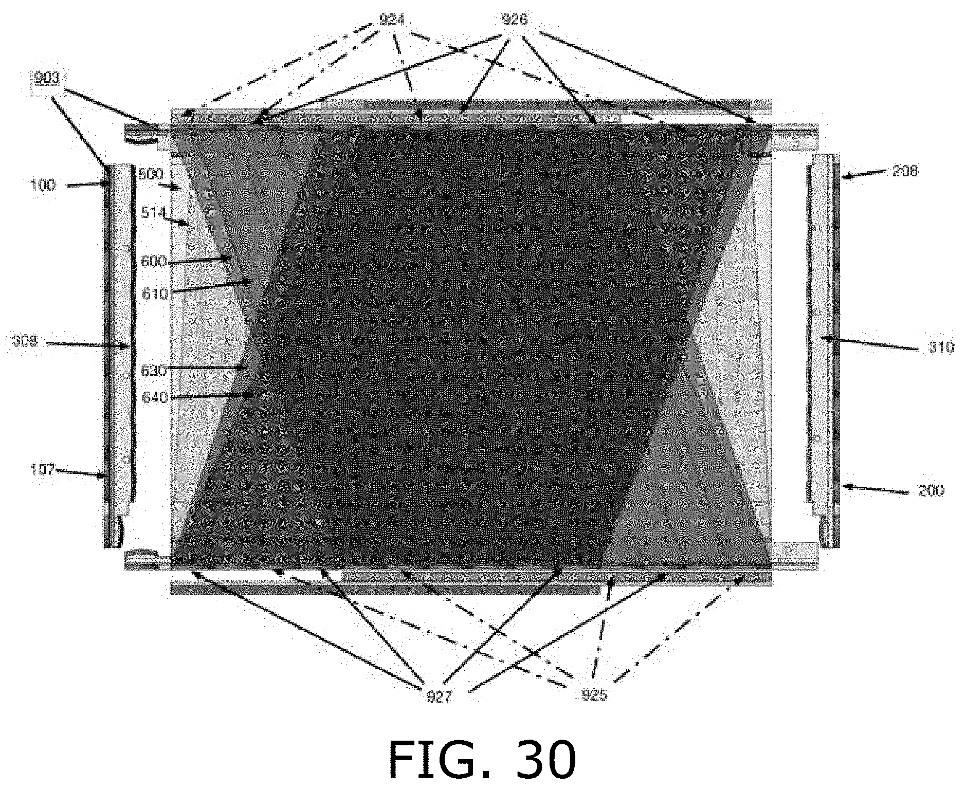
[0079] Reference is made to FIGS. 30 and 31, which are simplified illustrations of the number of overlapping light beams provided for touch detection in different portions of a touchscreen, featuring the beams of FIGS. 4, 14, 15 and 25-29, in accordance with an embodiment of the present invention. FIGS. 30 and 31 show the number of channels covering different portions of the detection area that utilize the beams illustrated in FIGS. 4, 14, 15 and 25-29. FIGS. 30 and 31 show that the outer portions of the detection area have fewer detection channels than the central portion of the detection area. FIGS. 30 and 31 indicate series 925, 927 of emitters and series 924, 926 of detectors that are active in providing the illustrated detection channels 600-619.
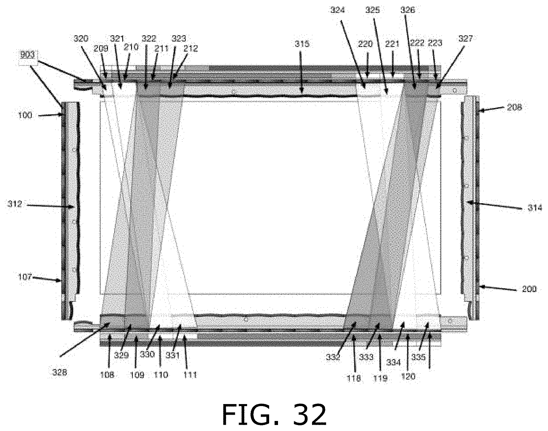
[0080] Reference is made to FIGS. 32 and 33, which are simplified illustrations of optical touchscreens having different optics for outer and inner beams crossing the screen, in accordance with an embodiment of the present invention. FIG. 32 shows detection channels provided along the outer edges of a detection area by beams similar to beams 484 and 486 in FIG. 5. Adding these beams to the system illustrated in FIGS. 30 and 31, provides the outer edge-related portions of the detection area with additional detection channels.
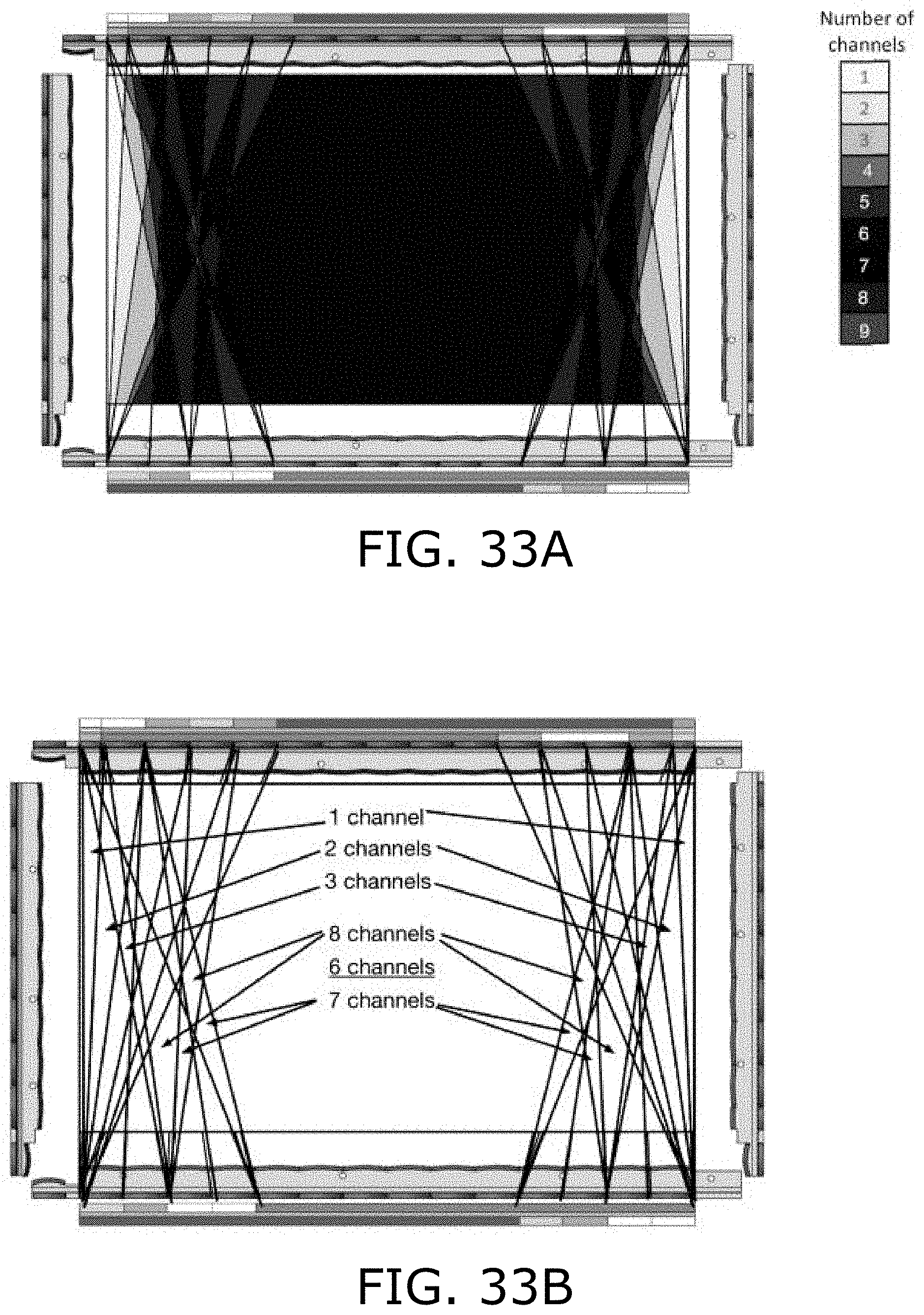
[0081] FIGS. 33A and 33B are two views of detection channel coverage in the system of FIGS. 30 and 31 when the additional beams and channels shown in FIG. 32 are provided along the edges of the detection area. FIG. 33A is color-coded, and FIG. 33B uses text and arrows to indicate the number of detection channels for each section of the touchscreen. FIGS. 33A and 33B show that portions of the detection area have up to nine detection channels. Additional beams with even larger emitter-detector offsets can be added to the optical sensor by modifying the lenses and the emitter-detector activation sequence, and such systems are also within the scope of the present invention.
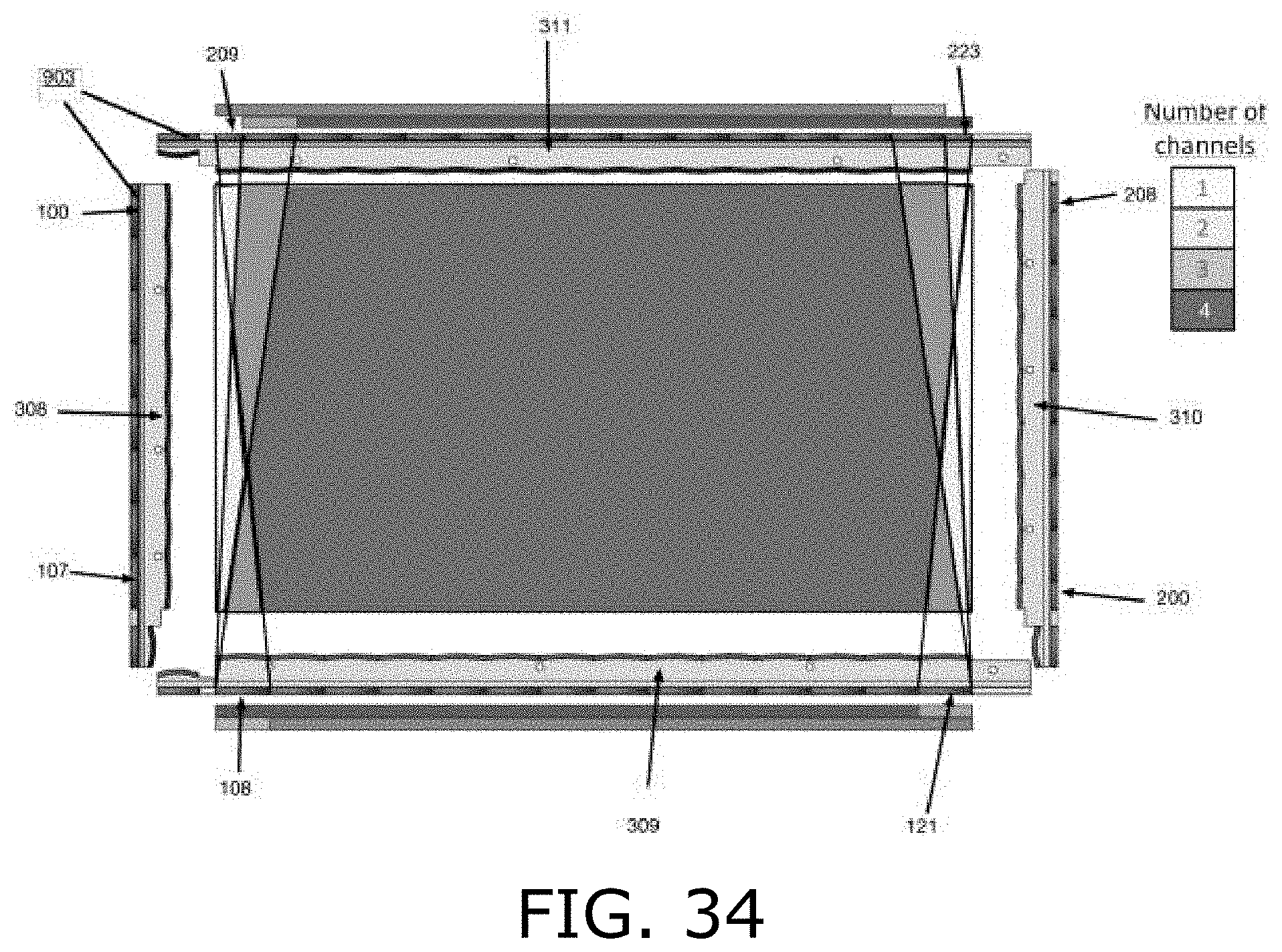
[0082] As discussed hereinabove, splitting light from each emitter into additional beams adds precision and enables better discrimination of ghost touches. Reference is made to FIG. 34, which is a simplified illustration of the number of overlapping light beams provided for touch detection in different portions of a touchscreen for a touchscreen whose lenses are configured to split each emitter beam into two diverging beams, not three, in accordance with an embodiment of the present invention. FIG. 34 shows the number of beams, or detection channels, that cover each part of a touchscreen when light from each emitter is split into four beams, namely, the two beams 484 and 485 of FIG. 6 and one beam to the left of beam 484 and another beam to the right of beam 485.
[0083] The edge portions of the touchscreen have fewer beams, or detection channels, than the center of the screen. In addition, a smaller portion of light from the emitters near the corners is used for touch detection as fewer channels can be used along the screen edges. Therefore, in certain embodiments of the invention, the light channels traversing the screen along the screen edges are shaped to be wider and therefore contain more signal strength than the channels in the middle of the screen. This requires that the lenses near the screen corners are longer than the other lenses, and the light channel is spread across a larger segment of the edge near the corner than the other light channels. In terms of calculating touch locations, each beam is assigned coordinates based on its center line and a weighted sum of all of these coordinates is calculated according to the amount that the signal is blocked. Thus, coordinates are also assigned to the edge beams and they are added to the weighted average, in the same way as the other beams. As a result of the larger lenses and wider beams near edges of the screen, the distance between the central line of a beam near an edge of the screen and its neighboring beam is greater than the distance between the central lines of other neighboring beams.
[0084] In the foregoing specification, the invention has been described with reference to specific exemplary embodiments thereof. It will, however, be evident that various modifications and changes may be made to the specific exemplary embodiments without departing from the broader spirit and scope of the invention. Accordingly, the specification and drawings are to be regarded in an illustrative rather than a restrictive sense.
* * * * *
D00000
D00001
D00002
D00003
D00004
D00005
D00006
D00007
D00008
D00009
D00010
D00011
D00012
D00013
D00014
D00015
D00016

D00017
D00018
D00019
D00020
D00021

D00022
D00023
D00024
D00025

D00026
D00027
D00028
D00029
D00030
D00031


XML
uspto.report is an independent third-party trademark research tool that is not affiliated, endorsed, or sponsored by the United States Patent and Trademark Office (USPTO) or any other governmental organization. The information provided by uspto.report is based on publicly available data at the time of writing and is intended for informational purposes only.
While we strive to provide accurate and up-to-date information, we do not guarantee the accuracy, completeness, reliability, or suitability of the information displayed on this site. The use of this site is at your own risk. Any reliance you place on such information is therefore strictly at your own risk.
All official trademark data, including owner information, should be verified by visiting the official USPTO website at www.uspto.gov. This site is not intended to replace professional legal advice and should not be used as a substitute for consulting with a legal professional who is knowledgeable about trademark law.